ga-b75m-d3h - support - gigabytedownload.gigabyte.us/.../mb_manual_ga-b75m-d3h_v1.1_e.pdf- 7 - 1-2...
TRANSCRIPT
GA-B75M-D3H
User's ManualRev. 110212ME-B75MD3H-1102R
MotherboardGA-B75M-D3H
Jul. 20, 2012
Jul. 20, 2012
Motherboard
GA-B75M-D3H
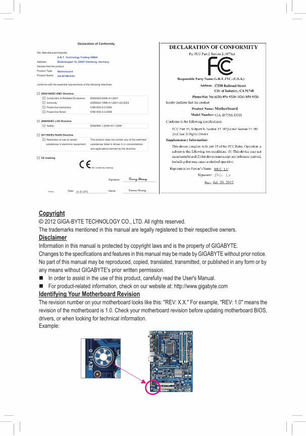
Copyright© 2012 GIGA-BYTE TECHNOLOGY CO., LTD. All rights reserved.The trademarks mentioned in this manual are legally registered to their respective owners.DisclaimerInformation in this manual is protected by copyright laws and is the property of GIGABYTE.Changes to the specifications and features in this manual may be made by GIGABYTE without prior notice.No part of this manual may be reproduced, copied, translated, transmitted, or published in any form or by any means without GIGABYTE's prior written permission.
� In order to assist in the use of this product, carefully read the User's Manual. � For product-related information, check on our website at: http://www.gigabyte.com
Identifying Your Motherboard RevisionThe revision number on your motherboard looks like this: "REV: X.X." For example, "REV: 1.0" means the revision of the motherboard is 1.0. Check your motherboard revision before updating motherboard BIOS, drivers, or when looking for technical information.Example:
- 3 -
Table of Contents
GA-B75M-D3H Motherboard Layout ...............................................................................4GA-B75M-D3H Motherboard Block Diagram ...................................................................5
Chapter 1 Hardware Installation .....................................................................................61-1 Installation Precautions .................................................................................... 61-2 ProductSpecifications ...................................................................................... 71-3 Installing the CPU ............................................................................................ 91-4 Installing the Memory ....................................................................................... 91-5 Installing an Expansion Card ......................................................................... 101-6 Back Panel Connectors .................................................................................. 101-7 Internal Connectors ........................................................................................ 12
Chapter 2 BIOS Setup ..................................................................................................182-1 Startup Screen ............................................................................................... 182-2 M.I.T. .............................................................................................................. 192-3 System ........................................................................................................... 232-4 BIOS Features ............................................................................................... 242-5 Peripherals ..................................................................................................... 262-6 Power Management ....................................................................................... 282-7 Save & Exit ..................................................................................................... 29
Chapter 3 Drivers Installation ........................................................................................30Regulatory Statements .............................................................................................. 31
- 4 -
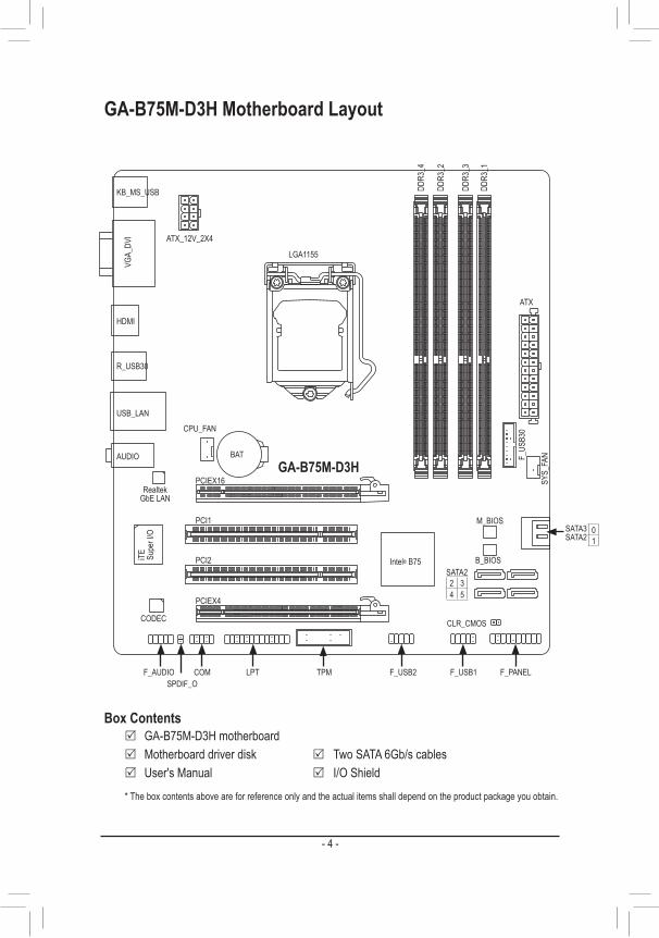
GA-B75M-D3H Motherboard Layout
* The box contents above are for reference only and the actual items shall depend on the product package you obtain.
Box Contents 5 GA-B75M-D3H motherboard 5 Motherboard driver disk 5 Two SATA 6Gb/s cables 5 User's Manual 5 I/O Shield
KB_MS_USB
CPU_FAN
LGA1155
ATX
GA-B75M-D3H
F_AUDIO
AUDIO
M_BIOS
DDR3
_4
DDR3
_3
DDR3
_2
DDR3
_1
BAT
F_PANEL
ATX_12V_2X4
Intel® B75SATA22 34 5
F_US
B30
R_USB30
CODEC CLR_CMOS
B_BIOS
VGA_
DVI
USB_LAN
PCIEX16
PCI1
PCI2
PCIEX4
SPDIF_OF_USB1F_USB2LPT TPMCOM
SYS_
FAN
HDMI
Realtek GbE LAN
iTE Supe
r I/O SATA3
SATA201
- 5 -
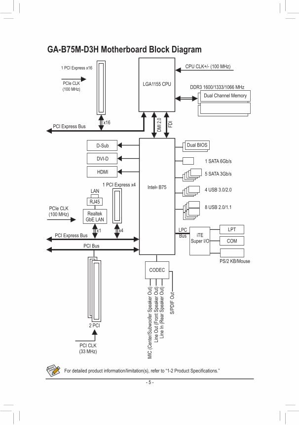
GA-B75M-D3H Motherboard Block Diagram
PS/2 KB/Mouse
COM
LPTLPC Bus
Line O
ut (F
ront
Spea
ker O
ut)MI
C (C
enter
/Sub
woofe
r Spe
aker
Out)
Line I
n (Re
ar S
peak
er O
ut)
S/PD
IF O
ut
CODEC
LGA1155 CPU
PCI Express Bus
CPU CLK+/- (100 MHz)
PCIe CLK(100 MHz)
1 PCI Express x16
x16
DMI 2
.0
FDI
DDR3 1600/1333/1066 MHzDual Channel Memory
LAN
RJ45
PCI Express Bus
PCIe CLK (100 MHz) Realtek
GbE LAN
1 PCI Express x4
x4x1
Dual BIOSD-Sub
DVI-D
HDMI
1 SATA 6Gb/s
4 USB 3.0/2.0
5 SATA 3Gb/s
8 USB 2.0/1.1
Intel® B75
PCI Bus
PCI CLK (33 MHz)
2 PCI
iTE Super I/O
Fordetailedproductinformation/limitation(s),referto“1-2ProductSpecifications.”

- 6 -
Chapter 1 Hardware Installation1-1 Installation PrecautionsThe motherboard contains numerous delicate electronic circuits and components which can become damaged as a result of electrostatic discharge (ESD). Prior to installation, carefully read the user's manual and follow these procedures:
• Prior to installation, make sure the chassis is suitable for the motherboard. • Prior to installation, do not remove or break motherboard S/N (Serial Number) sticker or
warranty sticker provided by your dealer. These stickers are required for warranty validation. • Always remove the AC power by unplugging the power cord from the power outlet before
installing or removing the motherboard or other hardware components. • When connecting hardware components to the internal connectors on the motherboard, make
sure they are connected tightly and securely. • When handling the motherboard, avoid touching any metal leads or connectors. • It is best to wear an electrostatic discharge (ESD) wrist strap when handling electronic
components such as a motherboard, CPU or memory. If you do not have an ESD wrist strap, keepyourhandsdryandfirsttouchametalobjecttoeliminatestaticelectricity.
• Prior to installing the motherboard, please have it on top of an antistatic pad or within an electrostatic shielding container.
• Before unplugging the power supply cable from the motherboard, make sure the power supply has been turned off.
• Before turning on the power, make sure the power supply voltage has been set according to the local voltage standard.
• Before using the product, please verify that all cables and power connectors of your hardware components are connected.
• To prevent damage to the motherboard, do not allow screws to come in contact with the motherboard circuit or its components.
• Make sure there are no leftover screws or metal components placed on the motherboard or within the computer casing.
• Do not place the computer system on an uneven surface. • Do not place the computer system in a high-temperature environment. • Turning on the computer power during the installation process can lead to damage to system
components as well as physical harm to the user. • If you are uncertain about any installation steps or have a problem related to the use of the product,pleaseconsultacertifiedcomputertechnician.
- 7 -
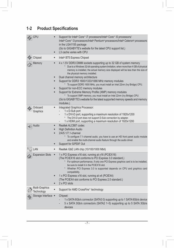
1-2 ProductSpecificationsCPU � Support for Intel® Core™ i7 processors/Intel® Core™ i5 processors/
Intel® Core™ i3 processors/Intel® Pentium® processors/Intel® Celeron® processors in the LGA1155 package(Go to GIGABYTE's website for the latest CPU support list.)
� L3 cache varies with CPU
Chipset � Intel® B75 Express Chipset
Memory � 4 x 1.5V DDR3 DIMM sockets supporting up to 32 GB of system memory * Due to a Windows 32-bit operating system limitation, when more than 4 GB of physical
memory is installed, the actual memory size displayed will be less than the size of the physical memory installed.
� Dual channel memory architecture � Support for DDR3 1600/1333/1066 MHz memory modules
* To support DDR3 1600 MHz, you must install an Intel 22nm (Ivy Bridge) CPU. � Support for non-ECC memory modules � SupportforExtremeMemoryProfile(XMP)memorymodules
* To support XMP memory, you must install an Intel 22nm (Ivy Bridge) CPU.(Go to GIGABYTE's website for the latest supported memory speeds and memory modules.)
Onboard Graphics
� Integrated Graphics Processor: - 1 x D-Sub port - 1 x DVI-D port, supporting a maximum resolution of 1920x1200 * The DVI-D port does not support D-Sub connection by adapter. - 1 x HDMI port, supporting a maximum resolution of 1920x1200
Audio � Realtek ALC887 codec � HighDefinitionAudio � 2/4/5.1/7.1-channel
* Toconfigure7.1-channelaudio,youhavetouseanHDfrontpanelaudiomoduleand enable the multi-channel audio feature through the audio driver.
� Support for S/PDIF Out
LAN � Realtek GbE LAN chip (10/100/1000 Mbit)
Expansion Slots � 1 x PCI Express x16 slot, running at x16 (PCIEX16)(The PCIEX16 slot conforms to PCI Express 3.0 standard.)
* For optimum performance, if only one PCI Express graphics card is to be installed, be sure to install it in the PCIEX16 slot.
* Whether PCI Express 3.0 is supported depends on CPU and graphics card compatibility.
� 1 x PCI Express x16 slot, running at x4 (PCIEX4)(The PCIEX4 slot conforms to PCI Express 2.0 standard.)
� 2 x PCI slotsMulti-Graphics Technology � Support for AMD CrossFire™ technology
Storage Interface � Chipset: - 1 x SATA 6Gb/s connector (SATA3 0) supporting up to 1 SATA 6Gb/s device - 5 x SATA 3Gb/s connectors (SATA2 1~5) supporting up to 5 SATA 3Gb/s
devices
- 8 -
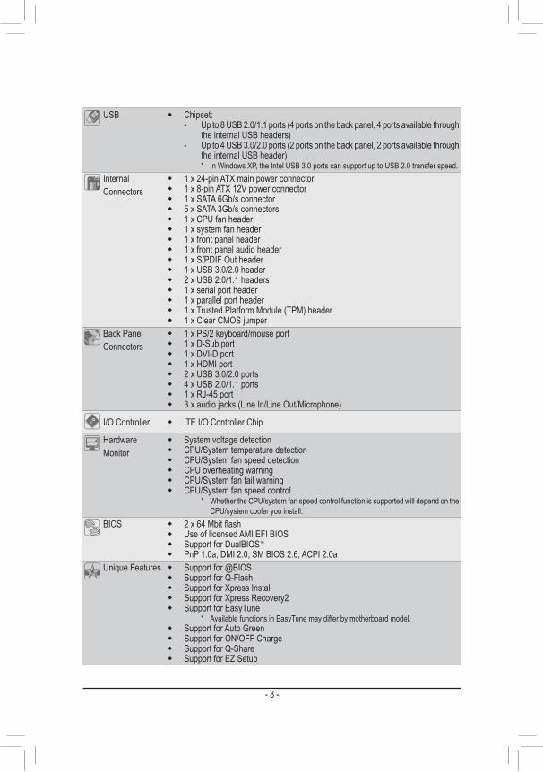
USB � Chipset: - Up to 8 USB 2.0/1.1 ports (4 ports on the back panel, 4 ports available through
the internal USB headers) - Up to 4 USB 3.0/2.0 ports (2 ports on the back panel, 2 ports available through
the internal USB header) * In Windows XP, the Intel USB 3.0 ports can support up to USB 2.0 transfer speed.
Internal Connectors
� 1 x 24-pin ATX main power connector � 1 x 8-pin ATX 12V power connector � 1 x SATA 6Gb/s connector � 5 x SATA 3Gb/s connectors � 1 x CPU fan header � 1 x system fan header � 1 x front panel header � 1 x front panel audio header � 1 x S/PDIF Out header � 1 x USB 3.0/2.0 header � 2 x USB 2.0/1.1 headers � 1 x serial port header � 1 x parallel port header � 1 x Trusted Platform Module (TPM) header � 1xClearCMOSjumper
Back Panel Connectors
� 1 x PS/2 keyboard/mouse port � 1 x D-Sub port � 1 x DVI-D port � 1 x HDMI port � 2 x USB 3.0/2.0 ports � 4 x USB 2.0/1.1 ports � 1 x RJ-45 port � 3xaudiojacks(LineIn/LineOut/Microphone)
I/O Controller � iTE I/O Controller Chip
Hardware Monitor
� System voltage detection � CPU/System temperature detection � CPU/System fan speed detection � CPU overheating warning � CPU/System fan fail warning � CPU/System fan speed control
* Whether the CPU/system fan speed control function is supported will depend on the CPU/system cooler you install.
BIOS � 2x64Mbitflash � Use of licensed AMI EFI BIOS � Support for DualBIOS™
� PnP 1.0a, DMI 2.0, SM BIOS 2.6, ACPI 2.0aUnique Features � Support for @BIOS
� Support for Q-Flash � Support for Xpress Install � Support for Xpress Recovery2 � Support for EasyTune
* Available functions in EasyTune may differ by motherboard model. � Support for Auto Green � Support for ON/OFF Charge � Support for Q-Share � Support for EZ Setup
- 9 -
Bundled Software
� Norton Internet Security (OEM version) � Intel® Rapid Start Technology � Intel® Smart Connect Technology � Intel® Small Business Advantage
Operating System � Support for Microsoft® Windows 8/7/XP
Form Factor � Micro ATX Form Factor; 24.4cm x 22.0cm
* GIGABYTEreservestherighttomakeanychangestotheproductspecificationsandproduct-relatedinformationwithoutprior notice.
* Please visit the Support & Downloads\Utility page on GIGABYTE's website to check the supported operating system(s) for the software listed in the "Unique Features" and "Bundled Software" columns.
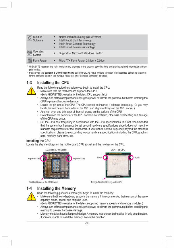
1-3 Installing the CPURead the following guidelines before you begin to install the CPU: • Make sure that the motherboard supports the CPU.
(Go to GIGABYTE's website for the latest CPU support list.) • Always turn off the computer and unplug the power cord from the power outlet before installing the
CPU to prevent hardware damage. • Locate the pin one of the CPU. The CPU cannot be inserted if oriented incorrectly. (Or you may
locate the notches on both sides of the CPU and alignment keys on the CPU socket.) • Apply an even and thin layer of thermal grease on the surface of the CPU. • Do not turn on the computer if the CPU cooler is not installed, otherwise overheating and damage
of the CPU may occur. • SettheCPUhostfrequencyinaccordancewiththeCPUspecifications.Itisnotrecommendedthatthesystembusfrequencybesetbeyondhardwarespecificationssinceitdoesnotmeetthestandard requirements for the peripherals. If you wish to set the frequency beyond the standard specifications,pleasedosoaccordingtoyourhardwarespecificationsincludingtheCPU,graphicscard, memory, hard drive, etc.
Installing the CPULocate the alignment keys on the motherboard CPU socket and the notches on the CPU.
NotchAlignment KeyAlignment Key Notch
LGA1155 CPULGA1155 CPU Socket
Pin One Corner of the CPU Socket Triangle Pin One Marking on the CPU
1-4 Installing the MemoryRead the following guidelines before you begin to install the memory: • Make sure that the motherboard supports the memory. It is recommended that memory of the same
capacity, brand, speed, and chips be used.(Go to GIGABYTE's website for the latest supported memory speeds and memory modules.)
• Always turn off the computer and unplug the power cord from the power outlet before installing the memory to prevent hardware damage.
• Memory modules have a foolproof design. A memory module can be installed in only one direction. If you are unable to insert the memory, switch the direction.
- 10 -
Dual Channel Memory ConfigurationThis motherboard provides four DDR3 memory sockets and supports Dual Channel Technology. After the memory is installed, the BIOS will automatically detect the specifications and capacity of the memory. Enabling Dual Channel memory mode will double the original memory bandwidth.The four DDR3 memory sockets are divided into two channels and each channel has two memory sockets as following:
�Channel A: DDR3_1, DDR3_3 �Channel B: DDR3_2, DDR3_4
Due to CPU limitations, read the following guidelines before installing the memory in Dual Channel mode.1. Dual Channel mode cannot be enabled if only one DDR3 memory module is installed.2. When enabling Dual Channel mode with two or four memory modules, it is recommended that memory
of the same capacity, brand, speed, and chips be used and installed in the same colored DDR3 sockets. For optimum performance, when enabling Dual Channel mode with two memory modules, we recommend that you install them in the DDR3_1 and DDR3_2 sockets.
1-5 Installing an Expansion CardRead the following guidelines before you begin to install an expansion card: • Make sure the motherboard supports the expansion card. Carefully read the manual that came
with your expansion card. • Always turn off the computer and unplug the power cord from the power outlet before installing an
expansion card to prevent hardware damage.
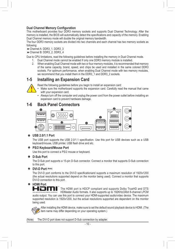
1-6 Back Panel Connectors
USB 2.0/1.1 PortThe USB port supports the USB 2.0/1.1 specification. Use this port for USB devices such as a USB keyboard/mouse, USB printer, USB flash drive and etc.PS/2 Keyboard/Mouse PortUse this port to connect a PS/2 mouse or keyboard.D-Sub PortThe D-Sub port supports a 15-pin D-Sub connector. Connect a monitor that supports D-Sub connection to this port.DVI-D Port (Note)
The DVI-D port conforms to the DVI-D specificationand supports a maximum resolution of 1920x1200 (the actual resolutions supported depend on the monitor being used). Connect a monitor that supports DVI-D connection to this port.HDMI Port
The HDMI port is HDCP compliant and supports Dolby TrueHD and DTS HDMaster Audio formats. It also supports up to 192KHz/24bit 8-channel LPCM
audio output. You can use this port to connect your HDMI-supported audio/video device. The maximum supported resolution is 1920x1200, but the actual resolutions supported are dependent on the monitor being used.
After installing the HDMI device, make sure to set the default sound playback device to HDMI. (The item name may differ depending on your operating system.)
(Note) The DVI-D port does not support D-Sub connection by adapter.
- 11 -
Toconfigure7.1-channelaudio,youhavetouseanHDfrontpanelaudiomoduleandenablethemulti-channel audio feature through the audio driver.
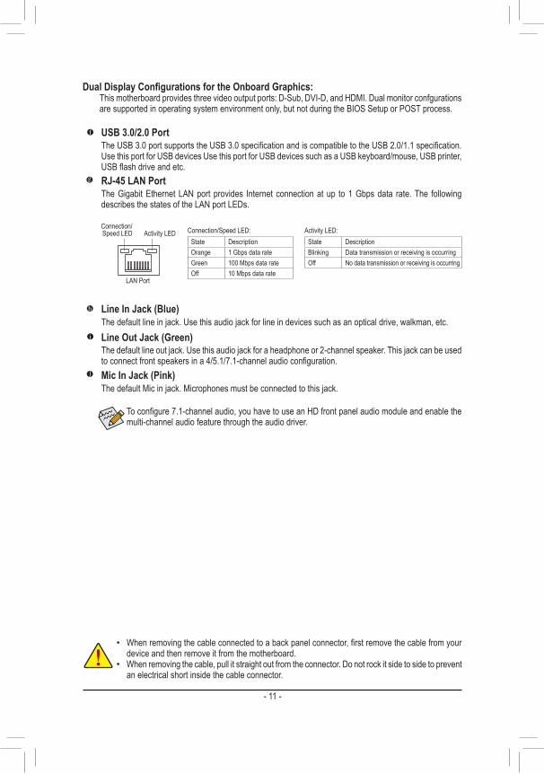
Line In Jack (Blue)Thedefaultlineinjack.Usethisaudiojackforlineindevicessuchasanopticaldrive,walkman,etc.Line Out Jack (Green)Thedefaultlineoutjack.Usethisaudiojackforaheadphoneor2-channelspeaker.Thisjackcanbeusedtoconnectfrontspeakersina4/5.1/7.1-channelaudioconfiguration.Mic In Jack (Pink)ThedefaultMicinjack.Microphonesmustbeconnectedtothisjack.
Activity LEDConnection/Speed LED
LAN Port
Connection/Speed LED:State DescriptionOrange 1 Gbps data rateGreen 100 Mbps data rateOff 10 Mbps data rate
Activity LED:State DescriptionBlinking Data transmission or receiving is occurringOff No data transmission or receiving is occurring
USB 3.0/2.0 PortTheUSB3.0portsupportstheUSB3.0specificationandiscompatibletotheUSB2.0/1.1specification.Use this port for USB devices Use this port for USB devices such as a USB keyboard/mouse, USB printer, USBflashdriveandetc.RJ-45 LAN PortThe Gigabit Ethernet LAN port provides Internet connection at up to 1 Gbps data rate. The following describes the states of the LAN port LEDs.
DualDisplayConfigurationsfortheOnboardGraphics:This motherboard provides three video output ports: D-Sub, DVI-D, and HDMI. Dual monitor confgurations are supported in operating system environment only, but not during the BIOS Setup or POST process.
• Whenremovingthecableconnectedtoabackpanelconnector,firstremovethecablefromyourdevice and then remove it from the motherboard.
• When removing the cable, pull it straight out from the connector. Do not rock it side to side to prevent an electrical short inside the cable connector.
- 12 -
1-7 Internal Connectors
Read the following guidelines before connecting external devices: • First make sure your devices are compliant with the connectors you wish to connect. • Before installing the devices, be sure to turn off the devices and your computer. Unplug the power
cord from the power outlet to prevent damage to the devices. • After installing the device and before turning on the computer, make sure the device cable has
been securely attached to the connector on the motherboard.
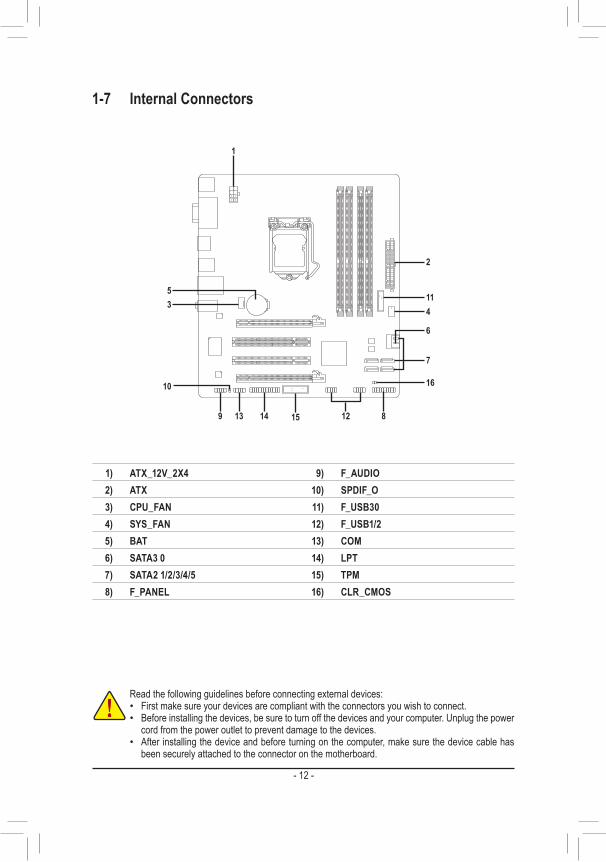
1) ATX_12V_2X42) ATX3) CPU_FAN4) SYS_FAN5) BAT6) SATA3 07) SATA2 1/2/3/4/58) F_PANEL
9) F_AUDIO10) SPDIF_O11) F_USB3012) F_USB1/213) COM14) LPT15) TPM16) CLR_CMOS
1
4
2
11
6
16
9 12
10
53
7
14 1513 8
- 13 -
DEBUG PORT
131
2412
ATX
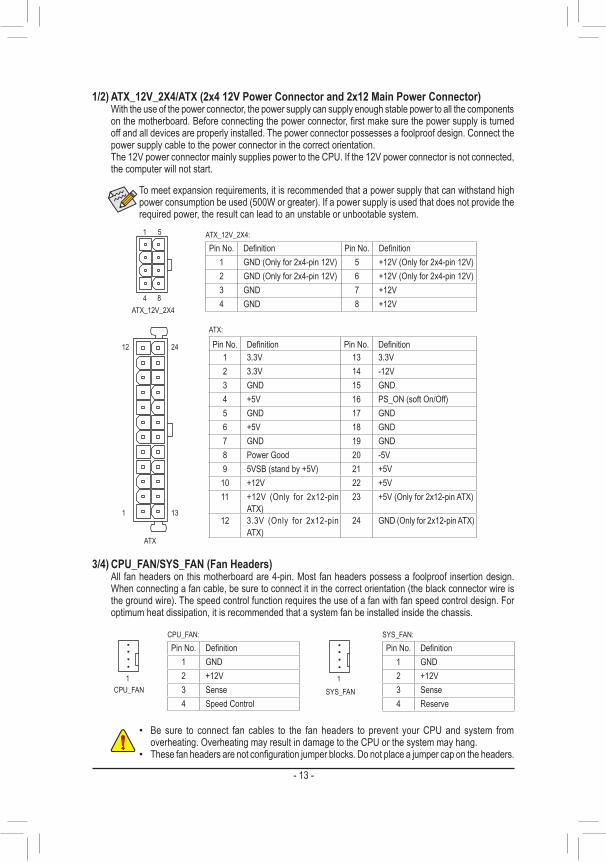
1/2) ATX_12V_2X4/ATX (2x4 12V Power Connector and 2x12 Main Power Connector) With the use of the power connector, the power supply can supply enough stable power to all the components
onthemotherboard.Beforeconnectingthepowerconnector,firstmakesurethepowersupplyisturnedoff and all devices are properly installed. The power connector possesses a foolproof design. Connect the power supply cable to the power connector in the correct orientation.
The 12V power connector mainly supplies power to the CPU. If the 12V power connector is not connected, the computer will not start.
To meet expansion requirements, it is recommended that a power supply that can withstand high power consumption be used (500W or greater). If a power supply is used that does not provide the required power, the result can lead to an unstable or unbootable system.
ATX:
Pin No. Definition Pin No. Definition1 3.3V 13 3.3V2 3.3V 14 -12V3 GND 15 GND4 +5V 16 PS_ON (soft On/Off)5 GND 17 GND6 +5V 18 GND7 GND 19 GND8 Power Good 20 -5V9 5VSB (stand by +5V) 21 +5V
10 +12V 22 +5V11 +12V (Only for 2x12-pin
ATX)23 +5V (Only for 2x12-pin ATX)
12 3.3V (Only for 2x12-pin ATX)
24 GND (Only for 2x12-pin ATX)
DEBUG PORT
ATX_12V_2X44
1
8
5 ATX_12V_2X4:Pin No. Definition Pin No. Definition
1 GND (Only for 2x4-pin 12V) 5 +12V (Only for 2x4-pin 12V)2 GND (Only for 2x4-pin 12V) 6 +12V (Only for 2x4-pin 12V)3 GND 7 +12V4 GND 8 +12V
3/4) CPU_FAN/SYS_FAN (Fan Headers) All fan headers on this motherboard are 4-pin. Most fan headers possess a foolproof insertion design.
When connecting a fan cable, be sure to connect it in the correct orientation (the black connector wire is the ground wire). The speed control function requires the use of a fan with fan speed control design. For optimum heat dissipation, it is recommended that a system fan be installed inside the chassis.
• Be sure to connect fan cables to the fan headers to prevent your CPU and system from overheating. Overheating may result in damage to the CPU or the system may hang.
• Thesefanheadersarenotconfigurationjumperblocks.Donotplaceajumpercapontheheaders.
SYS_FAN
DEBUG PORT
1CPU_FAN
DEBUG PORT
1
CPU_FAN:Pin No. Definition
1 GND2 +12V3 Sense4 Speed Control
SYS_FAN:Pin No. Definition
1 GND2 +12V3 Sense4 Reserve
- 14 -
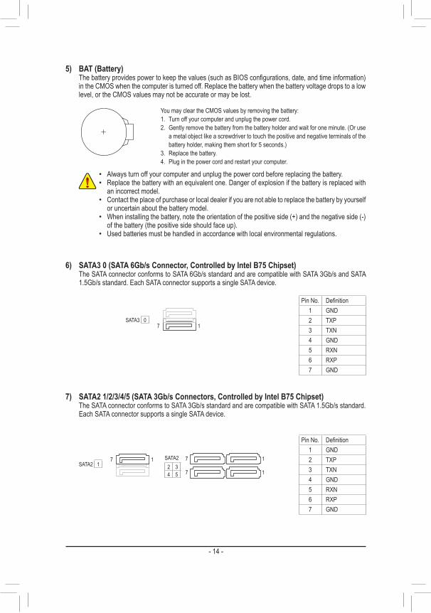
5) BAT (Battery) Thebatteryprovidespowertokeepthevalues(suchasBIOSconfigurations,date,andtimeinformation)
in the CMOS when the computer is turned off. Replace the battery when the battery voltage drops to a low level, or the CMOS values may not be accurate or may be lost.
You may clear the CMOS values by removing the battery:1. Turn off your computer and unplug the power cord.2. Gently remove the battery from the battery holder and wait for one minute. (Or use
ametalobjectlikeascrewdrivertotouchthepositiveandnegativeterminalsofthebattery holder, making them short for 5 seconds.)
3. Replace the battery.4. Plug in the power cord and restart your computer.
• Always turn off your computer and unplug the power cord before replacing the battery. • Replace the battery with an equivalent one. Danger of explosion if the battery is replaced with
an incorrect model. • Contact the place of purchase or local dealer if you are not able to replace the battery by yourself
or uncertain about the battery model. • When installing the battery, note the orientation of the positive side (+) and the negative side (-)
of the battery (the positive side should face up). • Used batteries must be handled in accordance with local environmental regulations.
7
7
1
1
DEBUG PORT
DEBUG PORT
DEBUG PORT
DEBUG PORT
SATA22 34 5
7 1
7 1
0SATA3
1SATA2
7) SATA2 1/2/3/4/5 (SATA 3Gb/s Connectors, Controlled by Intel B75 Chipset) The SATA connector conforms to SATA 3Gb/s standard and are compatible with SATA 1.5Gb/s standard.
Each SATA connector supports a single SATA device.
6) SATA3 0 (SATA 6Gb/s Connector, Controlled by Intel B75 Chipset) The SATA connector conforms to SATA 6Gb/s standard and are compatible with SATA 3Gb/s and SATA
1.5Gb/s standard. Each SATA connector supports a single SATA device.
Pin No. Definition1 GND2 TXP3 TXN4 GND5 RXN6 RXP7 GND
Pin No. Definition1 GND2 TXP3 TXN4 GND5 RXN6 RXP7 GND
- 15 -
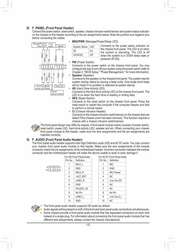
The front panel design may differ by chassis. A front panel module mainly consists of power switch, reset switch, power LED, hard drive activity LED, speaker and etc. When connecting your chassis front panel module to this header, make sure the wire assignments and the pin assignments are matched correctly.
8) F_PANEL (Front Panel Header) Connect the power switch, reset switch, speaker, chassis intrusion switch/sensor and system status indicator
on the chassis to this header according to the pin assignments below. Note the positive and negative pins before connecting the cables.
• PW (Power Switch): Connects to the power switch on the chassis front panel. You may
configurethewaytoturnoffyoursystemusingthepowerswitch(refertoChapter 2, "BIOS Setup," "Power Management," for more information).
• Speaker (Speaker): Connects to the speaker on the chassis front panel. The system reports
system startup status by issuing a beep code. One single short beep will be heard if no problem is detected at system startup.
• HD (Hard Drive Activity LED): Connects to the hard drive activity LED on the chassis front panel. The
LED is on when the hard drive is reading or writing data. • RES (Reset Switch):
Connects to the reset switch on the chassis front panel. Press the reset switch to restart the computer if the computer freezes and fails to perform a normal restart.
• CI (Chassis Intrusion Header): Connects to the chassis intrusion switch/sensor on the chassis that can
detect if the chassis cover has been removed. This function requires a chassis with a chassis intrusion switch/sensor.
• MSG/PWR (Message/Power/Sleep LED):System Status LEDS0 OnS3/S4/S5 Off
Connects to the power status indicator on the chassis front panel. The LED is on when the system is operating. The LED is off when the system is in S3/S4 sleep state or powered off (S5).
MSG-
PW-
SPEA
K+
SPEA
K-MSG+
PW+
HD-
RES+
HD+
RES-
Hard Drive Activity LED
Reset Switch
DEBUG PORT
Power LED
12
1920
CI- CI
+
PWR-
PWR+
Message/Power/Sleep LED
Chassis Intrusion Header
Power Switch Speaker
9) F_AUDIO (Front Panel Audio Header) ThefrontpanelaudioheadersupportsIntelHighDefinitionaudio(HD)andAC'97audio.Youmayconnect
your chassis front panel audio module to this header. Make sure the wire assignments of the module connector match the pin assignments of the motherboard header. Incorrect connection between the module connector and the motherboard header will make the device unable to work or even damage it.
For HD Front Panel Audio: For AC'97 Front Panel Audio:
• The front panel audio header supports HD audio by default. • Audio signals will be present on both of the front and back panel audio connections simultaneously. • Some chassis provide a front panel audio module that has separated connectors on each wire
instead of a single plug. For information about connecting the front panel audio module that has different wire assignments, please contact the chassis manufacturer.
Pin No. Definition1 MIC2_L2 GND3 MIC2_R4 -ACZ_DET5 LINE2_R6 GND7 FAUDIO_JD8 No Pin9 LINE2_L
10 GND
Pin No. Definition1 MIC2 GND3 MIC Power4 NC5 Line Out (R)6 NC7 NC8 No Pin9 Line Out (L)
10 NC
12
910
- 16 -
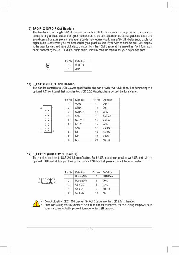
12) F_USB1/2 (USB 2.0/1.1 Headers) TheheadersconformtoUSB2.0/1.1specification.EachUSBheadercanprovidetwoUSBportsviaan
optional USB bracket. For purchasing the optional USB bracket, please contact the local dealer.
Pin No. Definition Pin No. Definition1 Power (5V) 6 USB DY+2 Power (5V) 7 GND3 USB DX- 8 GND4 USB DY- 9 No Pin5 USB DX+ 10 NC
• Do not plug the IEEE 1394 bracket (2x5-pin) cable into the USB 2.0/1.1 header. • Prior to installing the USB bracket, be sure to turn off your computer and unplug the power cord
from the power outlet to prevent damage to the USB bracket.
109
21
Pin No. Definition Pin No. Definition1 VBUS 11 D2+2 SSRX1- 12 D2-3 SSRX1+ 13 GND4 GND 14 SSTX2+5 SSTX1- 15 SSTX2-6 SSTX1+ 16 GND7 GND 17 SSRX2+8 D1- 18 SSRX2-9 D1+ 19 VBUS
10 NC 20 No Pin
11) F_USB30 (USB 3.0/2.0 Header) TheheaderconformstoUSB3.0/2.0specificationandcanprovidetwoUSBports.Forpurchasingthe
optional 3.5" front panel that provides two USB 3.0/2.0 ports, please contact the local dealer.
F_USB30 F_AUDIO(H)
DB_PORT
F_PANEL(NH) F_PANEL(H61M-D2)
ACPI_CPT(GA-IVB)
BIOS_PH(GA-IVB)
SMB_CPT(GA-IVB)
CLR_CMOSCIDIS_MEGP15_CPT(GA-IVB)
XDP_CPUXDP_PCH(GA-IVB)
TPMw/housing
Voltage measurement module(X58A-OC)
PCIe power connector (SATA)(X58A-OC)
DIP
123
DIP
123
DIP
123
DIP
1 2 3
1
1
1
1
BIOS Switcher (X58A-OC)
PWM Switch (X58A-OC)
M_SATA
PWM Switch (SW1)(X79-UD7)
DIP
12345
10
20 1
11
10) SPDIF_O (S/PDIF Out Header) This header supports digital S/PDIF Out and connects a S/PDIF digital audio cable (provided by expansion
cards) for digital audio output from your motherboard to certain expansion cards like graphics cards and sound cards. For example, some graphics cards may require you to use a S/PDIF digital audio cable for digital audio output from your motherboard to your graphics card if you wish to connect an HDMI display to the graphics card and have digital audio output from the HDMI display at the same time. For information about connecting the S/PDIF digital audio cable, carefully read the manual for your expansion card.
1
Pin No. Definition1 SPDIFO2 GND
- 17 -
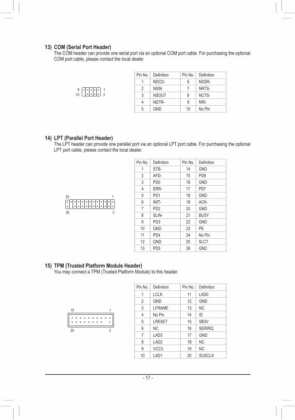
14) LPT (Parallel Port Header) The LPT header can provide one parallel port via an optional LPT port cable. For purchasing the optional
LPT port cable, please contact the local dealer.
26
25
2
1
DEBUG PORT
Pin No. Definition Pin No. Definition1 STB- 14 GND2 AFD- 15 PD63 PD0 16 GND4 ERR- 17 PD75 PD1 18 GND6 INIT- 19 ACK-7 PD2 20 GND8 SLIN- 21 BUSY9 PD3 22 GND
10 GND 23 PE11 PD4 24 No Pin12 GND 25 SLCT13 PD5 26 GND
Pin No. Definition Pin No. Definition1 NDCD- 6 NDSR-2 NSIN 7 NRTS-3 NSOUT 8 NCTS-4 NDTR- 9 NRI-5 GND 10 No Pin
13) COM (Serial Port Header) The COM header can provide one serial port via an optional COM port cable. For purchasing the optional
COM port cable, please contact the local dealer.
109
21
15) TPM (Trusted Platform Module Header) You may connect a TPM (Trusted Platform Module) to this header.
20
19
2
1
F_US
B30
F_AU
DIO(
H)
DB_P
ORT
F_PA
NEL(
NH)
F_PA
NEL
(H61
M-D2
)
ACPI
_CPT
(GA-
IVB)
BIOS
_PH
(GA-
IVB)
SMB_
CPT
(GA-
IVB)
CLR_
CMOS
CI DIS_
MEGP
15_C
PT(G
A-IV
B)
XDP_
CPU
XDP_
PCH
(GA-
IVB)
TPM
w/ho
using
Volta
ge m
easu
reme
nt mo
dule(
X58A
-OC)
PCIe
powe
r con
necto
r (SA
TA)(X
58A-
OC)
DIP
123
DIP
123
DIP
1 2 3
DIP
123
1 1
1
1
BIOS
Swi
tcher
(X58
A-OC
)
PWM
Switc
h (X5
8A-O
C)
M_SA
TA
PWM
Switc
h (SW
1)(X
79-U
D7)
DIP
12
34
5
Volta
ge m
easu
reme
nt po
ints(G
1.Snip
er 3)
BIOS
Swi
tcher
(SW
4)
Pin No. Definition Pin No. Definition1 LCLK 11 LAD02 GND 12 GND3 LFRAME 13 NC4 No Pin 14 ID5 LRESET 15 SB3V6 NC 16 SERIRQ7 LAD3 17 GND8 LAD2 18 NC9 VCC3 19 NC
10 LAD1 20 SUSCLK
- 18 -
BIOS (Basic Input and Output System) records hardware parameters of the system in the CMOS on the motherboard.Itsmajorfunctions includeconductingthePower-OnSelf-Test(POST)duringsystemstartup,saving system parameters and loading operating system, etc. BIOS includes a BIOS Setup program that allows theusertomodifybasicsystemconfigurationsettingsortoactivatecertainsystemfeatures.When the power is turned off, the battery on the motherboard supplies the necessary power to the CMOS to keeptheconfigurationvaluesintheCMOS.To access the BIOS Setup program, press the <Delete> key during the POST when the power is turned on.To upgrade the BIOS, use either the GIGABYTE Q-Flash or @BIOS utility. • Q-Flash allows the user to quickly and easily upgrade or back up BIOS without entering the operating system. • @BIOS is a Windows-based utility that searches and downloads the latest version of BIOS from the Internet
and updates the BIOS.
Chapter 2 BIOS Setup
• BecauseBIOSflashing ispotentially risky, ifyoudonotencounterproblemsusing thecurrentversionofBIOS, it is recommended thatyounotflash theBIOS.Toflash theBIOS,do itwithcaution.InadequateBIOSflashingmayresultinsystemmalfunction.
• It is recommended that you not alter the default settings (unless you need to) to prevent system instability or other unexpected results. Inadequately altering the settings may result in system's failure to boot. If this occurs, try to clear the CMOS values and reset the board to default values. (Refer to the "Load Optimized Defaults" section in this chapter or introductions of the battery/clear CMOSjumperinChapter1forhowtocleartheCMOSvalues.)
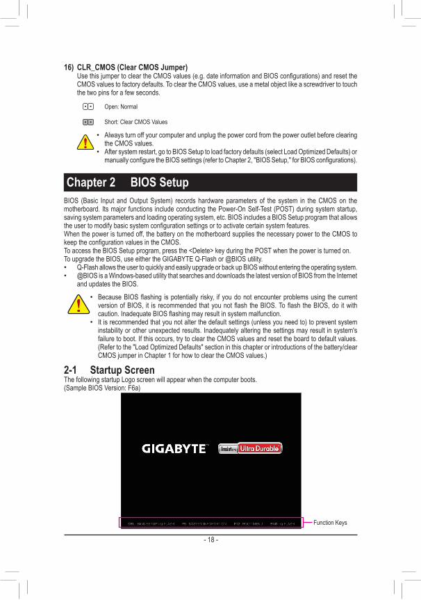
2-1 Startup ScreenThe following startup Logo screen will appear when the computer boots.(Sample BIOS Version: F6a)
Function Keys
16) CLR_CMOS (Clear CMOS Jumper) UsethisjumpertocleartheCMOSvalues(e.g.dateinformationandBIOSconfigurations)andresetthe
CMOSvaluestofactorydefaults.TocleartheCMOSvalues,useametalobjectlikeascrewdrivertotouchthe two pins for a few seconds.
Open: Normal
Short: Clear CMOS Values
• Always turn off your computer and unplug the power cord from the power outlet before clearing the CMOS values.
• After system restart, go to BIOS Setup to load factory defaults (select Load Optimized Defaults) or manuallyconfiguretheBIOSsettings(refertoChapter2,"BIOSSetup,"forBIOSconfigurations).
- 19 -
2-2 M.I.T.
Whether the system will work stably with the overclock/overvoltage settings you made is dependent onyouroverallsystemconfigurations.Incorrectlydoingoverclock/overvoltagemayresultindamageto CPU, chipset, or memory and reduce the useful life of these components. This page is for advanced users only and we recommend you not to alter the default settings to prevent system instability or other unexpected results. (Inadequately altering the settings may result in system's failure to boot. If this occurs, clear the CMOS values and reset the board to default values.)
This section provides information on the BIOS version, CPU base clock, CPU frequency, memory frequency, total memory size , CPU temperature, Vcore, and memory voltage.
On the main menu of the BIOS Setup program, press arrow keys to move among the items and press <Enter> to accept or enter a sub-menu. Or you can use your mouse to select the item you want.
• When the system is not stable as usual, select the Load Optimized Defaults item to set your system to its defaults.
• The BIOS Setup menus described in this chapter are for reference only and may differ by BIOS version.
` M.I.T. Current Status This screen provides information on CPU/memory frequencies/parameters.
` Advanced Frequency Settings & CPU/PCIe Base Clock
Allows you to manually set the CPU base clock and PCIe bus frequency in 0.01 MHz increments. (Default: Auto) Important:ItishighlyrecommendedthattheCPUfrequencybesetinaccordancewiththeCPUspecifications.
& Processor Graphics Clock Allowsyoutosettheonboardgraphicsclock.Theadjustablerangeisfrom400MHzto1600MHz.(Default:Auto)
& CPU Clock Ratio AllowsyoutoaltertheclockratiofortheinstalledCPU.TheadjustablerangeisdependentontheCPUbeing
installed. & CPU Frequency
Displays the current operating CPU frequency. ` Advanced CPU Core Features & CPU Clock Ratio, CPU Frequency
The settings above are synchronous to those under the same items on the Advanced Frequency Settings menu.
- 20 -
(Note 1) This item is present only when you install a CPU that supports this feature. For more information about Intel CPUs' unique features, please visit Intel's website.
(Note 2) This item is present only when you install a CPU and a memory module that support this feature.
& Intel(R) Turbo Boost Technology (Note 1)
Allows you to determine whether to enable the Intel CPU Turbo Boost technology. Auto lets the BIOS automaticallyconfigurethissetting.(Default:Auto)
& Turbo Ratio (1-Core Active~4-Core Active) (Note 1)
Allows you to set the CPU Turbo ratios for different number of active cores. Auto sets the CPU Turbo ratios accordingtotheCPUspecifications.(Default:Auto)
& Turbo Power Limit (Watts) Allows you to set a power limit for CPU Turbo mode. When the CPU power consumption exceeds the
specifiedpowerlimit,theCPUwillautomaticallyreducethecorefrequencyinordertoreducethepower.AutosetsthepowerlimitaccordingtotheCPUspecifications.(Default:Auto)
& Core Current Limit (Amps) AllowsyoutosetacurrentlimitforCPUTurbomode.WhentheCPUcurrentexceedsthespecifiedcurrent
limit, the CPU will automatically reduce the core frequency in order to reduce the current. Auto sets the powerlimitaccordingtotheCPUspecifications.(Default:Auto)
& CPU Core Enabled (Note 1)
Allows you to determine whether to enable all CPU cores. AutoletstheBIOSautomaticallyconfigurethissetting. (Default: Auto)
& Hyper-Threading Technology (Note 1)
Allows you to determine whether to enable multi-threading technology when using an Intel CPU that supports this function. This feature only works for operating systems that support multi-processor mode. Auto lets theBIOSautomaticallyconfigurethissetting.(Default:Auto)
& CPU Enhanced Halt (C1E) (Note 1) Enables or disables Intel CPU Enhanced Halt (C1E) function, a CPU power-saving function in system
halt state. When enabled, the CPU core frequency and voltage will be reduced during system halt state to decrease power consumption. AutoletstheBIOSautomaticallyconfigurethissetting.(Default:Auto)
& C3/C6 State Support (Note 1)
Allows you to determine whether to let the CPU enter C3/C6 mode in system halt state. When enabled, the CPU core frequency and voltage will be reduced during system halt state to decrease power consumption. The C3/C6 state is a more enhanced power-saving state than C1. AutoletstheBIOSautomaticallyconfigurethis setting. (Default: Auto)
& CPU Thermal Monitor (Note 1)
Enables or disables Intel CPU Thermal Monitor function, a CPU overheating protection function. When enabled, the CPU core frequency and voltage will be reduced when the CPU is overheated. Auto lets the BIOSautomaticallyconfigurethissetting.(Default:Auto)
& CPU EIST Function (Note 1)
Enables or disables Enhanced Intel SpeedStep Technology (EIST). Depending on CPU loading, Intel EIST technology can dynamically and effectively lower the CPU voltage and core frequency to decrease average power consumption and heat production. AutoletstheBIOSautomaticallyconfigurethissetting.(Default:Auto)
& ExtremeMemoryProfile(X.M.P.)(Note 2)
Allows the BIOS to read the SPD data on XMP memory module(s) to enhance memory performance when enabled.
�Disabled Disables this function. (Default) �Profile1 UsesProfile1settings. �Profile2(Note 2) UsesProfile2settings.
& System Memory Multiplier Allows you to set the system memory multiplier. Auto sets memory multiplier according to memory SPD
data. (Default: Auto)
- 21 -
& Memory Frequency (MHz) Thefirstmemoryfrequencyvalueisthenormaloperatingfrequencyofthememorybeingused;thesecond
isthememoryfrequencythatisautomaticallyadjustedaccordingtotheSystem Memory Multiplier settings. ` Advanced Memory Settings & ExtremeMemoryProfile(X.M.P.)(Note), System Memory Multiplier, Memory Frequency(MHz)
The settings above are synchronous to those under the same items on the Advanced Frequency Settings menu.
& Performance Enhance Allows the system to operate at three different performance levels.
�Normal Lets the system operate at its basic performance level. �Turbo Lets the system operate at its good performance level. (Default) �Extreme Lets the system operate at its best performance level.
& DRAM Timing Selectable Quick and Expert allows the Channel Interleaving, Rank Interleaving, and memory timing settings below
tobeconfigurable.Optionsare:Auto(default),Quick,Expert. & ProfileDDRVoltage
When using a non-XMP memory module or ExtremeMemoryProfile(X.M.P.) is set to Disabled, this item will display as 1.50V. When ExtremeMemoryProfile(X.M.P.) is set to Profile1 or Profile2, this item will display the value based on the SPD data on the XMP memory.
& ProfileVTTVoltage The value displayed here is dependent on the CPU being used.
& Channel Interleaving Enables or disables memory channel interleaving. Enabled allows the system to simultaneously access
different channels of the memory to increase memory performance and stability. Auto lets the BIOS automaticallyconfigurethissetting.(Default:Auto)
& Rank Interleaving Enables or disables memory rank interleaving. Enabled allows the system to simultaneously access different
ranks of the memory to increase memory performance and stability. Auto lets the BIOS automatically configurethissetting.(Default:Auto)
` Channel A/B Timing SettingsThis sub-menu provides memory timing settings for each channel of memory. The respective timing setting screensareconfigurableonlywhenDRAM Timing Selectable is set to Quick or Expert. Note: Your system may become unstable or fail to boot after you make changes on the memory timings. If this occurs, please reset the board to default values by loading optimized defaults or clearing the CMOS values.
` Advanced Voltage SettingsThis sub-menu allows you to set memory voltage.
` PC Health Status & Reset Case Open Status
�Disabled Keeps or clears the record of previous chassis intrusion status. (Default) �Enabled Clears the record of previous chassis intrusion status and the Case Openfieldwillshow
"No" at next boot. & Case Open
Displays the detection status of the chassis intrusion detection device attached to the motherboard CI header.Ifthesystemchassiscoverisremoved,thisfieldwillshow"Yes",otherwiseitwillshow"No".Toclear the chassis intrusion status record, set Reset Case Open Status to Enabled, save the settings to the CMOS, and then restart your system.
& CPU Vcore/Dram Voltage/+3.3V/+12V Displays the current system voltages.
(Note) This item is present only when you install a CPU and a memory module that support this feature.
- 22 -
& CPU/System Temperature Displays current CPU/system temperature.
& CPU/System FAN Speed Displays current CPU/system fan speeds.
& CPU Warning Temperature Sets the warning threshold for CPU temperature. When CPU temperature exceeds the threshold, BIOS
will emit warning sound. Options are: Disabled (default), 60oC/140oF, 70oC/158oF, 80oC/176oF, 90oC/194oF. & CPU/System Fan Fail Warning
Allows the system to emit warning sound if the fans are not connected or fail. Check the fan condition or fan connection when this occurs. (Default: Disabled)
& CPU Fan Speed Control AllowsyoutodeterminewhethertoenabletheCPUfanspeedcontrolfunctionandadjustthefanspeed.
�Normal Allows the CPU fan to run at different speeds according to the CPU temperature. You can adjustthefanspeedwithEasyTunebasedonyoursystemrequirements.(Default)
�Silent Allows the CPU fan to run at slow speeds. �Manual Allows you to control the CPU fan speed under the Slope PWM item. �Disabled Allows the CPU fan to run at full speeds.
& Slope PWM AllowsyoutocontroltheCPUfanspeed.ThisitemisconfigurableonlywhenCPU Fan Speed Control is
set to Manual. Options are: 0.75 PWM value /oC ~ 2.50 PWM value /oC. & System Fan Speed Control
Allowsyoutodeterminewhethertoenablethesystemfanspeedcontrolfunctionandadjustthefanspeed. �Normal Allows the system fan to run at different speeds according to the system temperature. You
canadjustthefanspeedwithEasyTunebasedonyoursystemrequirements.(Default) �Silent Allows the system fan to run at slow speeds. �Manual Allows you to control the system fan speed under the Slope PWM item. �Disabled Allows the system fan to run at full speeds.
& Slope PWM Allowsyoutocontrolthesystemfanspeed.ThisitemisconfigurableonlywhenSystem Fan Speed Control
is set to Manual. Options are: 0.75 PWM value /oC ~ 2.50 PWM value /oC.
` Miscellaneous Settings & PEGO - Gen X
Allows you to set the operation mode of the PCI Express slots to Gen 1, Gen 2, or Gen 3. Actual operation modeissubjecttothehardwarespecificationofeachslot.Forexample,thePCIExpressx1slotscansupport up to Gen 2 mode only. AutoletstheBIOSautomaticallyconfigurethissetting.(Default:Auto)
- 23 -
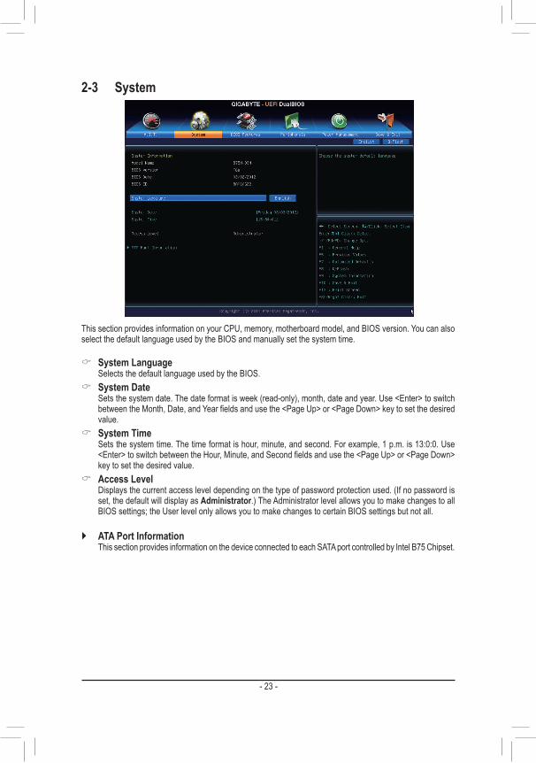
2-3 System
This section provides information on your CPU, memory, motherboard model, and BIOS version. You can also select the default language used by the BIOS and manually set the system time.
& System Language Selects the default language used by the BIOS.
& System Date Sets the system date. The date format is week (read-only), month, date and year. Use <Enter> to switch
betweentheMonth,Date,andYearfieldsandusethe<PageUp>or<PageDown>keytosetthedesiredvalue.
& System Time Sets the system time. The time format is hour, minute, and second. For example, 1 p.m. is 13:0:0. Use
<Enter>toswitchbetweentheHour,Minute,andSecondfieldsandusethe<PageUp>or<PageDown>key to set the desired value.
& Access Level Displays the current access level depending on the type of password protection used. (If no password is
set, the default will display as Administrator.) The Administrator level allows you to make changes to all BIOS settings; the User level only allows you to make changes to certain BIOS settings but not all.
` ATA Port Information This section provides information on the device connected to each SATA port controlled by Intel B75 Chipset.
- 24 -
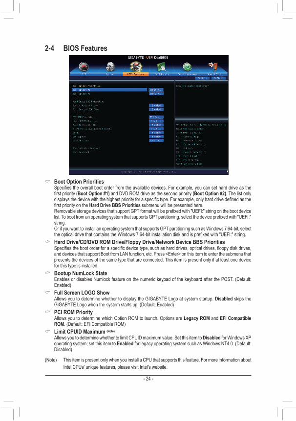
2-4 BIOS Features
& Boot Option Priorities Specifiestheoverallbootorderfromtheavailabledevices.Forexample,youcansetharddriveasthe
firstpriority(Boot Option #1) and DVD ROM drive as the second priority (Boot Option #2). The list only displaysthedevicewiththehighestpriorityforaspecifictype.Forexample,onlyharddrivedefinedasthefirstpriorityontheHard Drive BBS Priorities submenu will be presented here.
RemovablestoragedevicesthatsupportGPTformatwillbeprefixedwith"UEFI:"stringonthebootdevicelist.TobootfromanoperatingsystemthatsupportsGPTpartitioning,selectthedeviceprefixedwith"UEFI:"string.
Or if you want to install an operating system that supports GPT partitioning such as Windows 7 64-bit, select theopticaldrivethatcontainstheWindows764-bitinstallationdiskandisprefixedwith"UEFI:"string.
& Hard Drive/CD/DVD ROM Drive/Floppy Drive/Network Device BBS Priorities Specifiesthebootorderforaspecificdevicetype,suchasharddrives,opticaldrives,floppydiskdrives,
and devices that support Boot from LAN function, etc. Press <Enter> on this item to enter the submenu that presents the devices of the same type that are connected. This item is present only if at least one device for this type is installed.
& Bootup NumLock State Enables or disables Numlock feature on the numeric keypad of the keyboard after the POST. (Default:
Enabled) & Full Screen LOGO Show
Allows you to determine whether to display the GIGABYTE Logo at system startup. Disabled skips the GIGABYTE Logo when the system starts up. (Default: Enabled)
& PCI ROM Priority Allows you to determine which Option ROM to launch. Options are Legacy ROM and EFI Compatible
ROM. (Default: EFI Compatible ROM) & Limit CPUID Maximum (Note)
Allows you to determine whether to limit CPUID maximum value. Set this item to Disabled for Windows XP operating system; set this item to Enabled for legacy operating system such as Windows NT4.0. (Default: Disabled)
(Note) This item is present only when you install a CPU that supports this feature. For more information about Intel CPUs' unique features, please visit Intel's website.
- 25 -
& Execute Disable Bit (Note)
Enables or disables Intel Execute Disable Bit function. This function may enhance protection for the computer, reducingexposuretovirusesandmaliciousbufferoverflowattackswhenworkingwithitssupportingsoftwareand system. (Default: Enabled)
& Intel Virtualization Technology (Note)
Enables or disables Intel Virtualization Technology. Virtualization enhanced by Intel Virtualization Technology will allow a platform to run multiple operating systems and applications in independent partitions. With virtualization, one computer system can function as multiple virtual systems. (Default: Disabled)
& VT-d (Note)
Enables or disables Intel Virtualization Technology for Directed I/O. (Default: Enabled) & CSM Support
Enables or disables UEFI CSM (Compatibility Support Module) to support a legacy PC boot process. Enabled allows you to boot from an operating system that requires traditional option ROM. Auto lets the BIOSautomaticallyconfigurethissettingdependingontheoperatingsystembeinginstalled.
& Network stack Disables or enables booting from the network to install a GPT format OS, such as installing the OS from
the Windows Deployment Services server. (Default: Disable Link) & IPv6 PXE Boot Support
EnablesordisablesIPv6PXESupport.ThisitemisconfigurableonlywhenNetwork stack is enabled. & IPv4 PXE Boot Support
EnablesordisablesIPv4PXESupport.ThisitemisconfigurableonlywhenNetwork stack is enabled.
& Administrator Password Allowsyoutoconfigureanadministratorpassword.Press<Enter>onthisitem,typethepassword,and
thenpress<Enter>.Youwillberequestedtoconfirmthepassword.Typethepasswordagainandpress<Enter>. You must enter the administrator password (or user password) at system startup and when entering BIOS Setup. Differing from the user password, the administrator password allows you to make changes to all BIOS settings.
& User Password Allowsyoutoconfigureauserpassword.Press<Enter>onthisitem,typethepassword,andthenpress
<Enter>.Youwillberequestedtoconfirmthepassword.Typethepasswordagainandpress<Enter>.You must enter the administrator password (or user password) at system startup and when entering BIOS Setup. However, the user password only allows you to make changes to certain BIOS settings but not all.
To cancel the password, press <Enter> on the password item and when requested for the password, enter the correctonefirst.Whenpromptedforanewpassword,press<Enter>withoutenteringanypassword.Press<Enter>againwhenpromptedtoconfirm.
(Note) This item is present only when you install a CPU that supports this feature. For more information about Intel CPUs' unique features, please visit Intel's website.
- 26 -
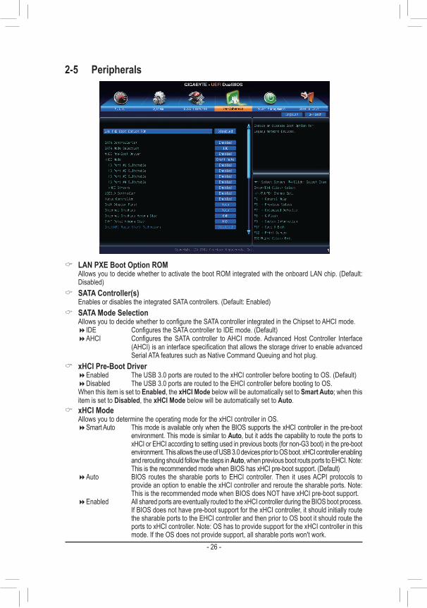
2-5 Peripherals
& LAN PXE Boot Option ROM Allows you to decide whether to activate the boot ROM integrated with the onboard LAN chip. (Default:
Disabled) & SATA Controller(s)
Enables or disables the integrated SATA controllers. (Default: Enabled) & SATA Mode Selection
AllowsyoutodecidewhethertoconfiguretheSATAcontrollerintegratedintheChipsettoAHCImode. �IDE ConfigurestheSATAcontrollertoIDEmode.(Default) �AHCI Configures theSATAcontroller toAHCImode.AdvancedHostController Interface
(AHCI)isaninterfacespecificationthatallowsthestoragedrivertoenableadvancedSerial ATA features such as Native Command Queuing and hot plug.
& xHCI Pre-Boot Driver �Enabled The USB 3.0 ports are routed to the xHCI controller before booting to OS. (Default) �Disabled The USB 3.0 ports are routed to the EHCI controller before booting to OS.
When this item is set to Enabled, the xHCI Mode below will be automatically set to Smart Auto; when this item is set to Disabled, the xHCI Mode below will be automatically set to Auto.
& xHCI Mode Allows you to determine the operating mode for the xHCI controller in OS.
�Smart Auto This mode is available only when the BIOS supports the xHCI controller in the pre-boot environment. This mode is similar to Auto, but it adds the capability to route the ports to xHCI or EHCI according to setting used in previous boots (for non-G3 boot) in the pre-boot environment. This allows the use of USB 3.0 devices prior to OS boot. xHCI controller enabling and rerouting should follow the steps in Auto, when previous boot routs ports to EHCI. Note: This is the recommended mode when BIOS has xHCI pre-boot support. (Default)
�Auto BIOS routes the sharable ports to EHCI controller. Then it uses ACPI protocols to provide an option to enable the xHCI controller and reroute the sharable ports. Note: This is the recommended mode when BIOS does NOT have xHCI pre-boot support.
�Enabled All shared ports are eventually routed to the xHCI controller during the BIOS boot process. If BIOS does not have pre-boot support for the xHCI controller, it should initially route the sharable ports to the EHCI controller and then prior to OS boot it should route the ports to xHCI controller. Note: OS has to provide support for the xHCI controller in this mode. If the OS does not provide support, all sharable ports won't work.
- 27 -
�Disabled The USB 3.0 ports are routed to the EHCI controller and the xHCI controller is turned off. All USB 3.0 devices function as High Speed devices regardless of xHCI software support/availability. If this item is set to Disabled, the HS Port #1/2/3/4 Switchable and xHCI Streamsitemsbelowwillbecomeunconfigurable.
& HS Port #1 Switchable~HS Port #4 Switchable �Enabled Corresponding USB 3.0 port is routed to xHCI. USB 3.0 device attached on port with
Super-Speed capability is visible to xHCI controller. (Default) �Disabled Corresponding USB 3.0 port is routed to EHCI. USB 3.0 device attached on port with
Super-Speed capability function as High-Speed. & xHCI Streams
Enables or disables multi-stream data transfer. Note:For Windows 7 USB 3.0 Streams support, devices may require UASP class driver updates from UASP driver vendors to be fully compatible with Intel USB 3.0 Streams Support. (Default: Enabled)
& USB2.0 Controller Enables or disables the integrated USB 2.0 controller. (Default: Enabled)
& Audio Controller Enables or disables the onboard audio function. (Default: Enabled) If you wish to install a 3rd party add-in audio card instead of using the onboard audio, set this item to
Disabled. & Init Display First
Specifes the frst initiation of the monitor display from the installed PCI graphics card, PCI Express graphics card, or the onboard graphics.
�Auto LetsBIOSautomaticallyconfigurethissetting.(Default) �IGFX Setstheonboardgraphicsasthefirstdisplay. �PEG SetsthePCIExpressgraphicscardonthePCIEX16slotasthefirstdisplay. �PCI SetsthegraphicscardonthePCIslotasthefirstdisplay.
& Internal Graphics Enables or disables the onboard graphics function. (Default: Auto)
& Internal Graphics Memory Size Allows you to set the onboard graphics memory size. Options are: 32M~1024M. (Default: 64M)
& DVMT Total Memory Size Allows you to allocate the DVMT memory size of the onboard graphics. Options are: 128M, 256M, MAX.
(Default: MAX) & Intel(R) Rapid Start Technology
EnablesordisablesIntelRapidStartTechnology.ThisitemisconfigurableonlywhenanSSDisinstalled.(Default: Disabled)
& Legacy USB Support Allows USB keyboard/mouse to be used in MS-DOS. (Default: Enabled)
& XHCI Hand-off Determines whether to enable XHCI Hand-off feature for an operating system without XHCI Hand-off
support. (Default: Enabled) & EHCI Hand-off
Determines whether to enable EHCI Hand-off feature for an operating system without EHCI Hand-off support. (Default: Disabled)
& Port 60/64 Emulation Enables or disables emulation of I/O ports 64h and 60h. This should be enabled for full legacy support
for USB keyboards/mice in MS-DOS or in operating system that does not natively support USB devices. (Default: Disabled)
& USB Storage Devices Displays a list of connected USB mass storage devices. This item appears only when a USB storage device
is installed.
- 28 -
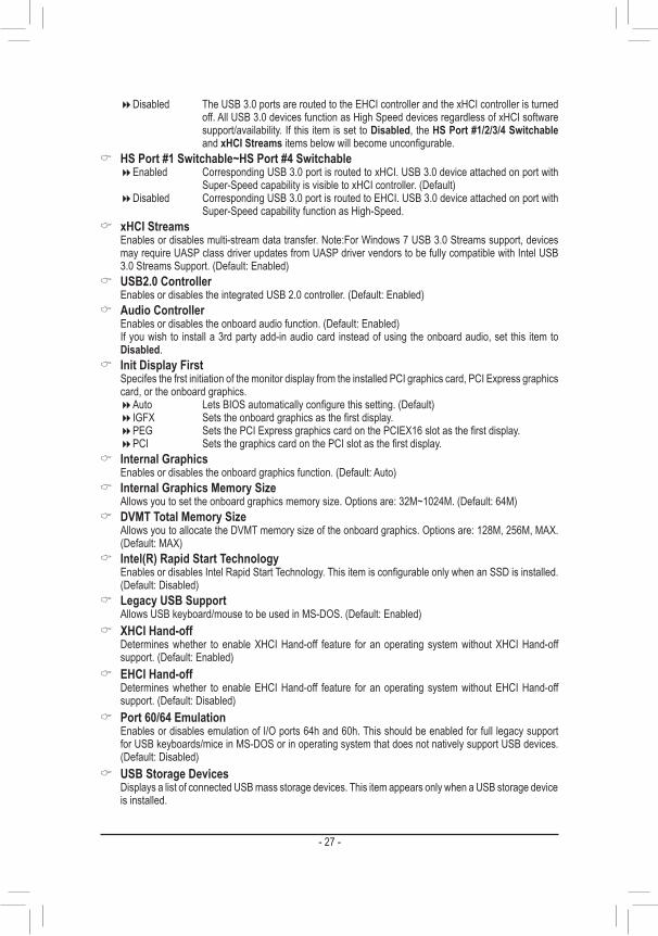
` Trusted Computing & TPM SUPPORT
Enables or disables Trusted Platform Module (TPM). Set this item to Enable when a TPM device is installed.(Default: Disable)
& OnBoard LAN Controller#1 Enables or disables the onboard LAN function. (Default: Enabled) If you wish to install a 3rd party add-in network card instead of using the onboard LAN, set this item to
Disabled.
` SuperIOConfiguration ThissectionprovidesinformationonthesuperI/Ochipandallowsyoutoconfiguretheserialportand
parallel port. & Serial Port A
Enables or disables the onboard serial port. (Default: Enabled) & Parallel Port
Enables or disables the onboard parallel port. (Default: Enabled)
` Intel(R) Smart Connect Technology & ISCTConfiguration
Enables or disables Intel Smart Connect Technology. (Default: Disabled)
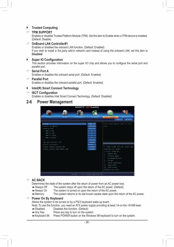
2-6 Power Management
& AC BACK Determines the state of the system after the return of power from an AC power loss.
�Always Off The system stays off upon the return of the AC power. (Default) �Always On The system is turned on upon the return of the AC power. �Memory The system returns to its last known awake state upon the return of the AC power.
& Power On By Keyboard Allows the system to be turned on by a PS/2 keyboard wake-up event. Note: To use this function, you need an ATX power supply providing at least 1A on the +5VSB lead.
�Disabled Disables this function. (Default) �Any Key Press any key to turn on the system. �Keyboard 98 Press POWER button on the Windows 98 keyboard to turn on the system.
- 29 -
& Resume by Alarm Determines whether to power on the system at a desired time. (Default: Disabled) If enabled, set the date and time as following:
�Wakeupday:Turnonthesystemataspecifictimeoneachdayoronaspecificdayinamonth. �Wake up hour/minute/second: Set the time at which the system will be powered on automatically.
Note: When using this function, avoid inadequate shutdown from the operating system or removal of the AC power, or the settings may not be effective.
& ErP Determines whether to let the system consume least power in S5 (shutdown) state. (Default: Disabled) Note: When this item is set to Enabled, the following functions will become unavailable: PME event wake
up, power on by mouse, power on by keyboard, and wake on LAN. & High Precision Event Timer (Note)
Enables or disables High Precision Event Timer (HPET) for Windows 7 operating system. (Default: Enabled) & Soft-Off by PWR-BTTN
ConfiguresthewaytoturnoffthecomputerinMS-DOSmodeusingthepowerbutton. �Instant-Off Press the power button and then the system will be turned off instantly. (Default) �Delay 4 Sec Press and hold the power button for 4 seconds to turn off the system. If the power
button is pressed for less than 4 seconds, the system will enter suspend mode. & Internal Graphics Standby Mode
Allows you to determine whether to let the onboard graphics enter standby mode to decrease power consumption. (Default: Enabled)
& Internal Graphics Deep Standby Mode Allows you to determine whether to let the onboard graphics enter deeper standby mode. (Default: Enabled)
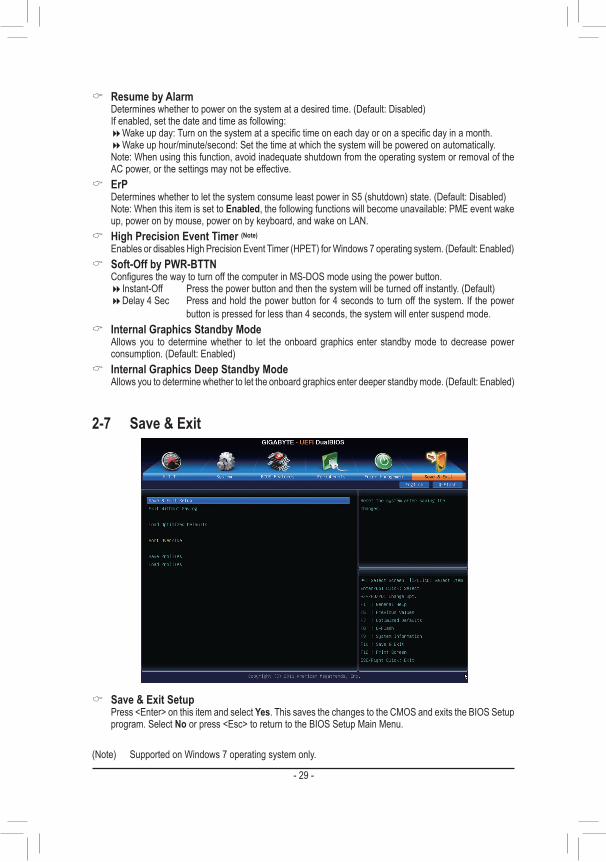
2-7 Save & Exit
& Save & Exit Setup Press <Enter> on this item and select Yes. This saves the changes to the CMOS and exits the BIOS Setup
program. Select No or press <Esc> to return to the BIOS Setup Main Menu.
(Note) Supported on Windows 7 operating system only.

- 30 -
& Exit Without Saving Press <Enter> on this item and select Yes. This exits the BIOS Setup without saving the changes made
in BIOS Setup to the CMOS. Select No or press <Esc> to return to the BIOS Setup Main Menu. & Load Optimized Defaults
Press <Enter> on this item and select Yes to load the optimal BIOS default settings. The BIOS defaults settings help the system to operate in optimum state. Always load the Optimized defaults after updating the BIOS or after clearing the CMOS values.
& Boot Override Allows you to select a device to boot immediately. Press <Enter> on the device you select and select Yes
toconfirm.Yoursystemwillrestartautomaticallyandbootfromthatdevice. & SaveProfiles
ThisfunctionallowsyoutosavethecurrentBIOSsettingstoaprofile.Youcancreateupto8profilesandsaveasSetupProfile1~SetupProfile8.Press<Enter>tocomplete.OryoucanselectSelect File in HDD/USB/FDDtosavetheprofiletoyourstoragedevice.
& LoadProfiles
If your system becomes unstable and you have loaded the BIOS default settings, you can use this function to load theBIOSsettings fromaprofilecreatedbefore,without thehasslesof reconfiguring theBIOSsettings.Firstselecttheprofileyouwishtoloadandthenpress<Enter>tocomplete.YoucanselectSelect File in HDD/USB/FDDtoinputtheprofilepreviouslycreatedfromyourstoragedeviceorloadtheprofileautomatically created by the BIOS, such as reverting the BIOS settings to the last settings that worked properly (last known good record).
Chapter 3 Drivers Installation • Beforeinstallingthedrivers,firstinstalltheoperatingsystem. • After installing the operating system, insert the motherboard driver disk into your optical drive. The
driver Autorun screen is automatically displayed which looks like that shown in the screen shot below. (If the driver Autorun screen does not appear automatically, go to My Computer, double-click the optical drive and execute the Run.exe program.)
After inserting the driver disk, "Xpress Install" will automatically scan your system and then list all the drivers that are recommended to install. You can click the Install All button and "Xpress Install" will install all the recommended drivers. Or click Install Single Items to manually select the drivers you wish to install.
- 31 -
Regulatory StatementsRegulatory NoticesThis document must not be copied without our written permission, and the contents there of must not be imparted to a third party nor be used for any unauthorized purpose. Contravention will be prosecuted. We believe that the information contained herein was accurate in all respects at the time of printing. GIGABYTE cannot, however, assume any responsibility for errors or omissions in this text. Also note that the information in this document is subjecttochangewithoutnoticeandshouldnotbeconstruedasacommitmentbyGIGABYTE.
Our Commitment to Preserving the EnvironmentIn addition to high-efficiencyperformance, allGIGABYTEmotherboards fulfillEuropeanUnion regulationsfor RoHS (Restriction of Certain Hazardous Substances in Electrical and Electronic Equipment) and WEEE (WasteElectricalandElectronicEquipment)environmentaldirectives,aswellasmostmajorworldwidesafetyrequirements. To prevent releases of harmful substances into the environment and to maximize the use of our natural resources, GIGABYTE provides the following information on how you can responsibly recycle or reuse most of the materials in your "end of life" product.
Restriction of Hazardous Substances (RoHS) Directive StatementGIGABYTE products have not intended to add and safe from hazardous substances (Cd, Pb, Hg, Cr+6, PBDE and PBB). The parts and components have been carefully selected to meet RoHS requirement. Moreover, we at GIGABYTE are continuing our efforts to develop products that do not use internationally banned toxic chemicals.
Waste Electrical & Electronic Equipment (WEEE) Directive StatementGIGABYTEwillfulfillthenationallawsasinterpretedfromthe2002/96/ECWEEE(WasteElectricalandElectronicEquipment)directive.TheWEEEDirectivespecifiesthetreatment,collection,recyclinganddisposalofelectricand electronic devices and their components. Under the Directive, used equipment must be marked, collected separately, and disposed of properly.
WEEE Symbol StatementThe symbol shown below is on the product or on its packaging, which indicates that this product must not be disposed of with other waste. Instead, the device should be taken to the waste collection centers for activation of the treatment, collection, recycling and disposal procedure. The separate collection and recycling of your waste equipment at the time of disposal will help to conserve natural resources and ensure that it is recycled in a manner that protects human health and the environment. For more information about where you can drop off your waste equipment for recycling, please contact
yourlocalgovernmentoffice,yourhouseholdwastedisposalserviceorwhereyoupurchasedtheproductfordetails of environmentally safe recycling.
� When your electrical or electronic equipment is no longer useful to you, "take it back" to your local or regional waste collection administration for recycling.
� If you need further assistance in recycling, reusing in your "end of life" product, you may contact us at the Customer Care number listed in your product's user's manual and we will be glad to help you with your effort.
Finally, we suggest that you practice other environmentally friendly actions by understanding and using the energy-saving features of this product (where applicable), recycling the inner and outer packaging (including shipping containers) this product was delivered in, and by disposing of or recycling used batteries properly. With your help, we can reduce the amount of natural resources needed to produce electrical and electronic equipment,minimizetheuseoflandfillsforthedisposalof"endoflife"products,andgenerallyimproveourquality of life by ensuring that potentially hazardous substances are not released into the environment and are disposed of properly.
- 32 -
Contact Us
GIGA-BYTE TECHNOLOGY CO., LTD.Address: No.6, Bao Chiang Road, Hsin-Tien Dist., New Taipei City 231,TaiwanTEL: +886-2-8912-4000, FAX: +886-2-8912-4003Tech. and Non-Tech. Support (Sales/Marketing) : http://ggts.gigabyte.com.twWEB address (English): http://www.gigabyte.comWEB address (Chinese): http://www.gigabyte.twYou may go to the GIGABYTE website, select your language in the language list on the top right corner of the website.
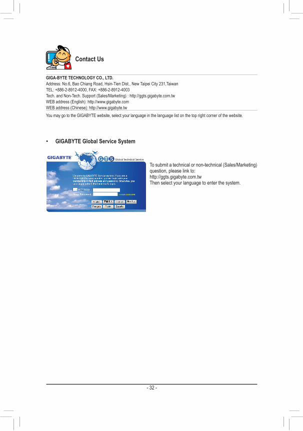
• GIGABYTE Global Service System
To submit a technical or non-technical (Sales/Marketing) question, please link to:http://ggts.gigabyte.com.twThen select your language to enter the system.