g6 sampler r0 - jiskoot sampler r0.pdfg6 gas sampler h31 issue no 0 page 3 abc item no description...
TRANSCRIPT

H31 Issue 0
OPERATING, INSTALLATION & MAINTENANCE MANUAL
FOR
G6 GAS SAMPLER
This Jiskoot Product is designed to provide outstanding service if correctly installed, used and maintained recognising the effects of the process conditions (temperature, pressure, wax/pour point, sediment, etc.). Truly representative sampling of crude oils etc., cannot be achieved by one single product in isolation. A well designed system and operating procedures as laid down in the Sampling Standards ISO 3171, API 8.2 and IP Chapter VI section 2 are mandatory. Please consult Jiskoot for further information and assistance. No part of this document may be reproduced or transmitted in any form or by any means, electronic or mechanical, for any purpose, without the express written permission of Jiskoot Ltd.
2007 Jiskoot Ltd. All rights reserved.
abc

H31 Issue 0

G6 Gas Sampler
T:\DOCUMENT\G6 GAS SAMPLER\MANUALS\G6 SAMPLER R0.DOC
abc
TABLE OF CONTENTS
1 WARRANTY ....................................................................................................... 1
2 INTRODUCTION................................................................................................. 1
3 OPERATING INSTRUCTIONS........................................................................... 1
4 GLOSSARY OF SPECIAL TERMS .................................................................... 2
5 FULL FUNCTIONAL DESCRIPTION ................................................................. 1
6 UTILITIES REFERENCE .................................................................................... 3
7 INSTALLATION DETAILS ................................................................................. 3
7.1 MINIMUM REQUIREMENTS ............................................................................... 3 7.2 TYPICAL SAMPLING SYSTEM INSTALLATION....................................................... 3 7.3 SAMPLE TAKE-OFF PROBE SELECTION, LOCATION AND INSTALLATION ................ 4
Selection of Sample Take-off Probe.................................................................... 4 Acceptable Sample Loops .................................................................................. 5
7.4 SAMPLE TAKE-OFF PROBE LOCATION AND INSTALLATION................................... 5 7.5 TYPICAL GAS SAMPLING CONFIGURATIONS ...................................................... 6
8 EQUIPMENT START-UP.................................................................................... 7
8.1 INITIAL START-UP AND LEAK TESTING............................................................... 7 8.2 SAMPLER STROKE ADJUSTMENT...................................................................... 7
9 MAINTENANCE AND TROUBLESHOOTING.................................................... 8
9.1 HEALTH AND SAFETY PRECAUTIONS ................................................................ 8 9.2 ANNUAL MAINTENANCE ................................................................................... 8 9.3 OVERHAUL INSTRUCTIONS .............................................................................. 8 9.4 TO REPLACE THE INLET VALVE 'O' RING............................................................ 9 9.5 TO REMOVE THE ACTUATOR CYLINDER AND BLOCK FROM THE SAMPLER BODY. 10 9.6 TO REMOVE INTERNAL SEALS AND 'O' RINGS FROM SAMPLER BODY. ................. 10 9.7 SAMPLER REASSEMBLY ................................................................................ 11
10 RECOMMENDED SPARES LIST ................................................................. 11
11 DISCLAIMER ................................................................................................ 12

G6 Gas Sampler
H31 Issue No 0 Page 1
abc
1 Warranty
This product should be supplied with a warranty card. Please complete and return it to register for warranty support.
In the event it is missing, to register for support, please contact us on +44 (0)1892 518000 or [email protected], quoting the Jiskoot Order Number or Serial No with the following information:
• Date installed
• Full installation site details, including contact details
• Maintenance and operator contact details (where different from above)
• Product comments/feedback
If the product has been supplied as part of a Jiskoot system or assembly, please complete the warranty card for the system.
2 Introduction
The Jiskoot G6 Gas Sampler provides accurate and reliable means of extracting gas samples from pipelines.
The sample size is fully adjustable. The G6 uses pressure balanced self-lubricating seals to maximise service intervals and all construction materials are selected to eliminate corrosion by contaminants. The complete design concept of the G6 is to combine reliability and accuracy with minimum maintenance. The G6 Gas Sampler can be completely overhauled in less than 15 minutes (Qualified and trained personnel).
The G6 operates at pipeline pressures between 5 and 200 barg and will provide repeatable sample sizes regardless of pressure fluctuations. It operates as a pressure balanced sampler ensuring samples are discharged as pipeline pressure and process. This minimises evaporation or condensation and ensures that each grab remains representative.
3 Operating Instructions
The G6 Gas Sampler is intended for incorporation into a Sampling System typically comprising Sample Take Off Probe, a controller to generate the control signal to operate the solenoid valve switching the regulated air or gas supply to the actuator and a sample receiver.
To operate the G6 Gas Sampler, ensure any isolating valves in the pipe work between the Sample Take-off Probe, the Sample Gas Inlet/Outlet Ports and the sample return line or vent, are open. Open any isolating valves between the Sample Outlet and the sample collection system.

G6 Gas Sampler
H31 Issue No 0 Page 2
abcThe time interval between each sample grab and the duration of the actuating pulse will have been adjusted during installation and commissioning. Depending on the type and method of determining grab intervals, the sample will operate automatically when the flow is detected in the main pipeline or the Controller is initiated.
4 Glossary of Special Terms
Grab - The action of the sampler in taking a sample of gas.
5 Full Functional Description
The G6 Gas Sampler is intended to be installed close to a sample take-off probe mounted in the system pipeline as described in section 7 of this manual.
The Sampler is pneumatically actuated from a regulated air or gas supply via a solenoid valve operated by the sampler controller.
A flow of gas is maintained from the pipeline via the sample take-off configuration used across the Gas Sampler through the two bi-directional Sample Gas Inlet /Outlet ports.
Item numbers referenced in this section are identified in fig 1.
Line pressure is applied to the Balance Port. This pressure is retained between the pair of main cartridge seal assemblies (Items 21/21a), the lower cartridge seal 21a pressing down on the annulus of the Spring Retainer (9), which is located within the body by the spring (22) pushing against the applied pressure. This ensures that the pressure required to lift the Seal (21b) between the Sample Chamber (25), and the Sample Outlet Port is, at all times, maintained above line pressure by the force exerted by the Spring.
Fig. 1 Sectional View of G6 Gas Sampler

G6 Gas Sampler
H31 Issue No 0 Page 3
abcItem No
Description Part Number
Item No
Description Part Number
1 Main Body (Rev 6) 36-1330-00 24 Actuator Cylinder 36-1331-00
2 Actuator Block 36-1332-00 5 Actuator Piston 36-1333-00
18 Piston Seal 37-0542-00 4 Spring 40-0112-00
6 Set Screw 99-0040-00 8 Displacement Adjuster 36-0920-00
7 Lock Nut 36-1335-00 3 Circlip 37-0608-00
26 Sample Ram 36-0919-00 10 Valve Body 36-1334-00
13 Check Valve Stem 36-1336-00 28 Spring 40-0113-00
23 Flat Washer 99-0043-00 11 Spring Retainer 99-0044-00
19 'O' Ring 37-0714-00 25 Sample Chamber 36-1337-00
21 Cartridge 37-0789-00 15 'O' Ring 36-0715-00
21a Cartridge 37-0789-00 22 Spring 40-0229-00
9 Spring Guide 36-3449-00 21b Cartridge 37-0789-00
12 Lock Nut 36-1202-00 13 Check Valve Insert 36-1341-00
33 CE Label 36-0700-00 32 Pan Head Screw 99-0058-00
6 Utilities Reference
Air pressure 80psig/5.5barg
Air Consumption Approximately 100ml free air per grab.
7 Installation Details
Fig 2 G6 Gas Sampler
NOTE: Thread tape must NOT be used on any joints associated with this equipment due the risk of pieces of tape becoming entrapped in the internal components. Use liquid thread sealants such as Loctite 572 or similar.
7.1 Minimum Requirements
The G6 Gas Sampler is intended for incorporation into a Sampling System typically comprising Sample Take Off Probe, a controller to generate the control signal to operate the solenoid valve switching the regulated air or gas supply to the actuator and a sample receiver.
7.2 Typical Sampling System Installation
All equipment required for the correct operation of the gas sampling system should be located and installed inside a suitable enclosure. The enclosure may require heating to keep all piping and cylinders at line pressure and temperature if the gas is wet. This will prevent condensation of the heavy products and liquids that may affect the sample validity.
G6 Gas Sampler
H31 Issue No 0 Page 4
abcThe Sample Cylinder, whether it be a fixed volume (variable pressure) type or the variable volume (constant pressure) version, should be mounted inside the enclosure close to the Gas Sampler.
The sampling system enclosure, being a fully functioning self-contained system, should be located as close to the Sample Take-off Probe as possible.
To prevent any trapped volume, the sample line from the probe to the sampling system enclosure should ideally be sloping upwards.
If the gas pressure applied to the Balance Port is to be supplied from an external source such as a Nitrogen supply and not directly from the Sample Inlet pipework, it is essential that the pressure is controlled to within 2 bar of the sample inlet pressure.
7.3 Sample Take-off Probe Selection, Location and Installation
Selection of Sample Take-off Probe
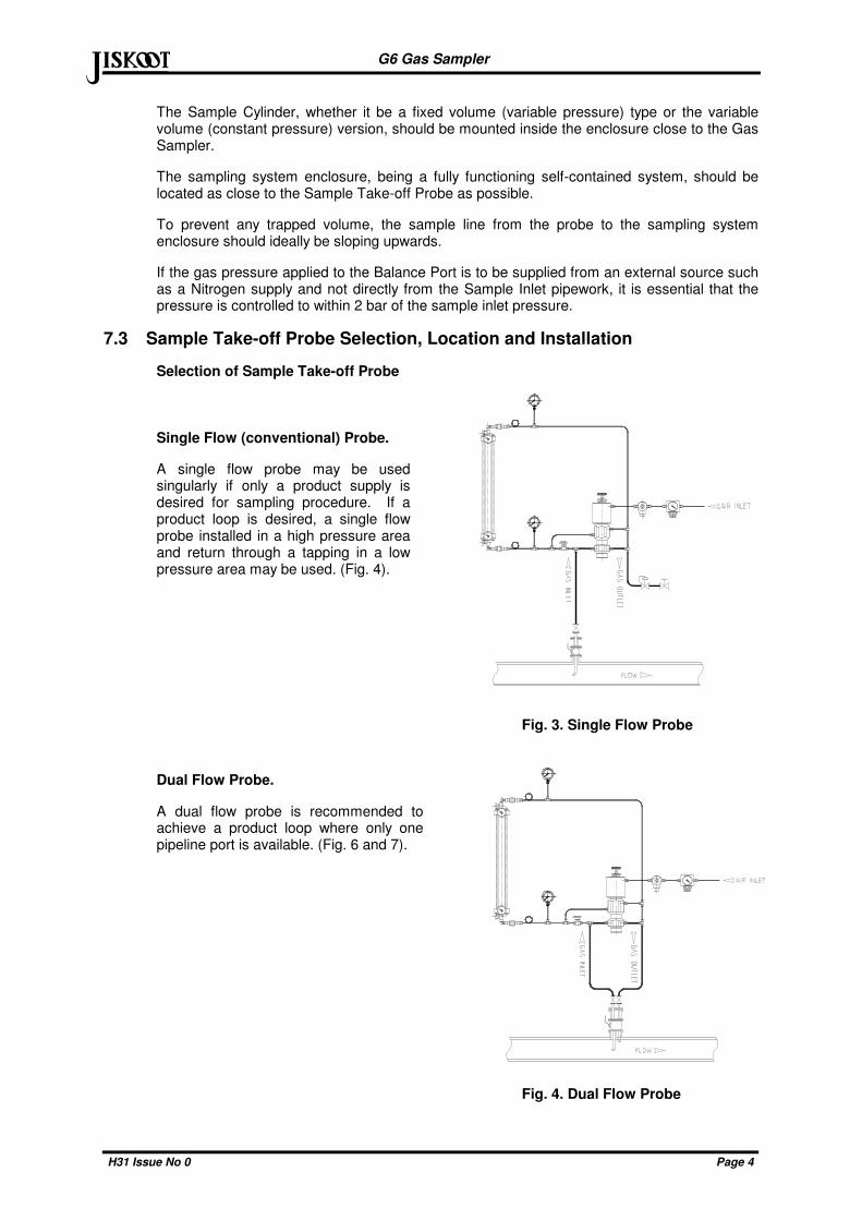
Single Flow (conventional) Probe.
A single flow probe may be used singularly if only a product supply is desired for sampling procedure. If a product loop is desired, a single flow probe installed in a high pressure area and return through a tapping in a low pressure area may be used. (Fig. 4).
Fig. 3. Single Flow Probe
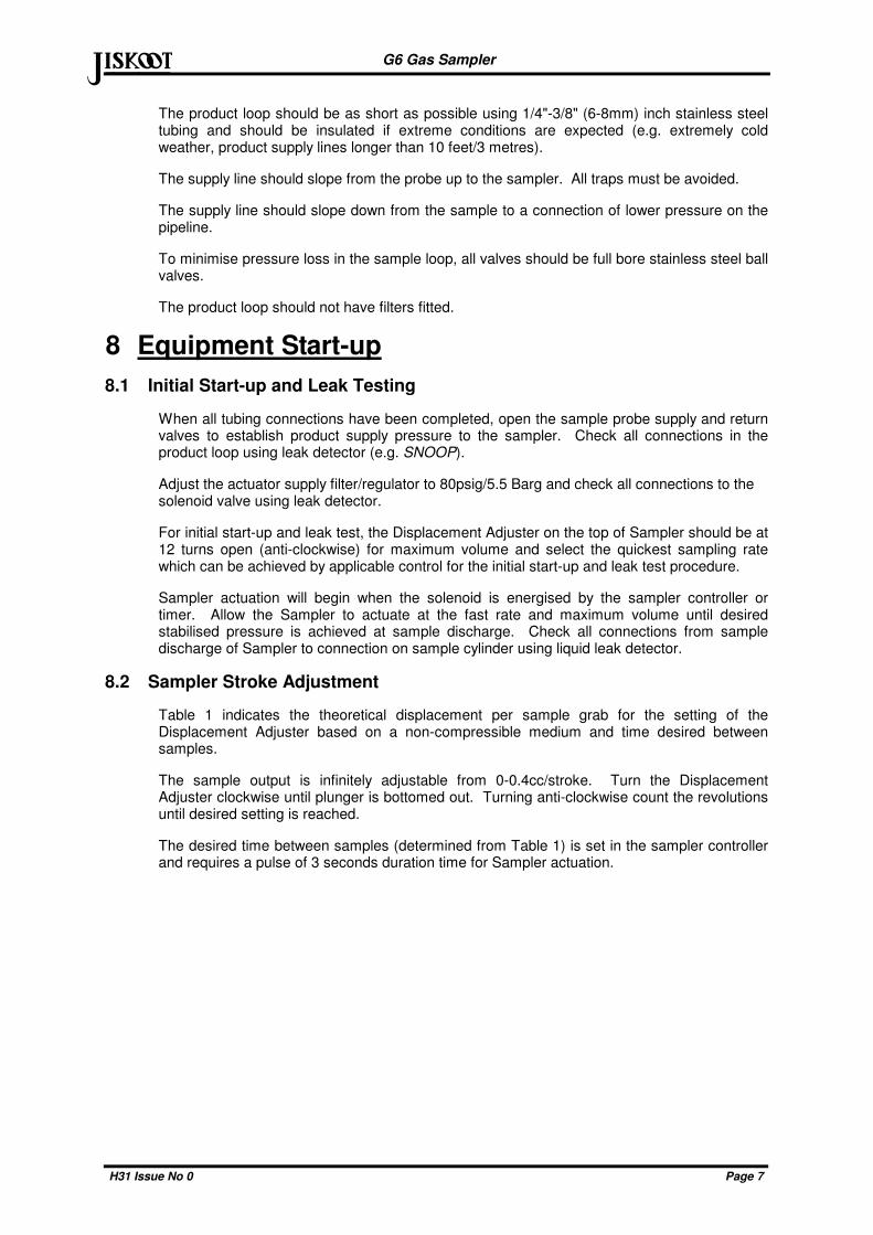
Dual Flow Probe.
A dual flow probe is recommended to achieve a product loop where only one pipeline port is available. (Fig. 6 and 7).
Fig. 4. Dual Flow Probe

G6 Gas Sampler
H31 Issue No 0 Page 5
abcAcceptable Sample Loops
Fig. 5 Fig. 6 Fig. 7
7.4 Sample Take-off Probe Location and Installation
The Sample Take-off Probe should be a minimum of five pipe diameters from any device which could cause aerosols or significant pressure drops.
The Sample Take-off Probe should not be located within the meter tube region as defined in AGA 3-1985 edition, Figure 4-8.
The Sample Take-off Probe should be mounted vertically in a horizontal run.
The Sample Take-off Probe should penetrate into the centre one-third of the pipeline.
The end of the Sample Take-off Probe should be cut parallel to the pipeline.
The Sample Take-off Probe should be stainless steel.
Fig. 8. PREFERRED PROBE LOCATION

G6 Gas Sampler
H31 Issue No 0 Page 6
abc
7.5 Typical Gas Sampling Configurations
Fig.9. Fixed Volume Sampling System
Fig.10. Constant Pressure Sampling System
G6 Gas Sampler
H31 Issue No 0 Page 7
abcThe product loop should be as short as possible using 1/4"-3/8" (6-8mm) inch stainless steel tubing and should be insulated if extreme conditions are expected (e.g. extremely cold weather, product supply lines longer than 10 feet/3 metres).
The supply line should slope from the probe up to the sampler. All traps must be avoided.
The supply line should slope down from the sample to a connection of lower pressure on the pipeline.
To minimise pressure loss in the sample loop, all valves should be full bore stainless steel ball valves.
The product loop should not have filters fitted.
8 Equipment Start-up
8.1 Initial Start-up and Leak Testing
When all tubing connections have been completed, open the sample probe supply and return valves to establish product supply pressure to the sampler. Check all connections in the product loop using leak detector (e.g. SNOOP).
Adjust the actuator supply filter/regulator to 80psig/5.5 Barg and check all connections to the solenoid valve using leak detector.
For initial start-up and leak test, the Displacement Adjuster on the top of Sampler should be at 12 turns open (anti-clockwise) for maximum volume and select the quickest sampling rate which can be achieved by applicable control for the initial start-up and leak test procedure.
Sampler actuation will begin when the solenoid is energised by the sampler controller or timer. Allow the Sampler to actuate at the fast rate and maximum volume until desired stabilised pressure is achieved at sample discharge. Check all connections from sample discharge of Sampler to connection on sample cylinder using liquid leak detector.
8.2 Sampler Stroke Adjustment
Table 1 indicates the theoretical displacement per sample grab for the setting of the Displacement Adjuster based on a non-compressible medium and time desired between samples.
The sample output is infinitely adjustable from 0-0.4cc/stroke. Turn the Displacement Adjuster clockwise until plunger is bottomed out. Turning anti-clockwise count the revolutions until desired setting is reached.
The desired time between samples (determined from Table 1) is set in the sampler controller and requires a pulse of 3 seconds duration time for Sampler actuation.

G6 Gas Sampler
H31 Issue No 0 Page 8
abc
SAMPLING RATE IN MINUTES FOR VESSEL INDICATED 31 DAY SAMPLING PERIOD 7 DAY SAMPLING PERIOD Sample Vessel Size In cc's Sample Vessel Size In cc's
No. of turns open on
Displacement Adjuster
Sample Displacement
per Stroke 1000 800 600 500 400 300 1000 800 600 500 400 300
1 0.042 1.9 2.3 2.9 3.7 4.7 6.2 0.4 0.5 0.7 0.8 1.1 1.4
2 0.083 3.7 4.7 5.8 7.4 9.3 12.4 0.8 1.1 1.3 1.7 2.1 2.8
3 0.125 5.6 7.0 8.7 11.2 14.0 18.6 0.3 1.6 2.0 2.5 3.2 4.2
4 0.167 7.4 9.3 11.6 14.9 18.6 24.8 1.7 2.1 2.6 3.4 4.2 5.6
5 0.208 9.3 11.6 14.5 18.6 23.3 31.0 2.1 2.6 3.3 4.2 5.3 7.0
6 0.250 11.2 14 17.4 22.3 27.9 37.2 2.5 3.2 3.9 5.0 6.3 8.4
7 0.292 13.0 16.3 20.3 26.0 32.6 43.4 2.9 3.7 4.6 5.9 7.4 9.8
8 0.333 14.9 18.6 23.3 29.8 37.2 49.6 3.4 4.2 5.3 6.7 8.4 11.2
9 0.375 16.7 20.9 26.2 33.5 41.9 55.8 3.8 4.7 5.9 7.6 9.5 12.6
10 0.417 18.6 23.3 29.1 37.2 46.5 62.0 4.2 5.3 6.6 8.4 10.5 14.0
11 0.458 20.5 25.6 32.0 40.9 51.2 68.2 4.6 5.8 7.2 9.2 11.6 15.4
12 0.500 22.3 27.9 34.9 44.6 55.8 74.4 5.0 6.3 7.9 10.1 12.6 16.8
9 Maintenance and Troubleshooting
9.1 Health and Safety Precautions
The G6 Gas Sampler may be used in applications involving hazardous products. Care must be taken to avoid contamination by any product trapped within the internal components that may be released as the Sampler is stripped down.
9.2 Annual Maintenance
The G6 Gas Sampler is designed to operate continuously for a period of about 1,000,000 grabs or 12 months before a major overhaul, however this service interval will be affected by the type of product being sampled, particularly the amount of particulate matter such as sand, and therefore can not be guaranteed. The service intervals will therefore need to be determined from the experience gained on the particular application.
The G6 Gas Sampler should be removed from the pipeline and taken to a clean area for servicing, servicing by trained and competent personnel.
It is essential that soft vice jaws are used whenever components are required to be held, and that all components, particularly those with sealing faces are thoroughly cleaned of dirt and other contamination by degreasing and drying prior to re-assembly.
9.3 Overhaul Instructions
Envisaged as being preformed via trained and competent personnel
Remove the Gas Sampler from sampling system enclosure.
The stainless steel tubing from the solenoid and the process connections to the Sampler must be disconnected before removing the Sampler. It is not necessary to remove the fittings from the Sampler.

G6 Gas Sampler
H31 Issue No 0 Page 9
abc
9.4 To replace the Inlet Valve 'O' ring
Fig.12. Sectional View - Main Seals
To replace the Inlet Valve 'O' ring (item 19), unscrew the Lock Nut (12) from the Main Body and withdraw the Valve Body (10). Cut the 'O' ring off the head of the Check Valve Stem (13) and stretch the new 'O' ring over the head of the Check Valve Stem using a light coat of Castrol Spheerol MP2 (or equivalent) grease.
The Inlet Valve Assembly should be refitted as described in section 9.7

G6 Gas Sampler
H31 Issue No 0 Page 10
abc9.5 To remove the Actuator Cylinder and Block from the Sampler Body.
The Actuator Cylinder and Block are threaded into the top of the Main Body. The Actuator Cylinder houses the Actuator Piston, Spring and Piston and should not be dismantled unless one of these items needs replacing. To replace the Piston Seal, unscrew the Actuator Cylinder and Block from the Main Body, remove the Circlip (3) and withdraw the Actuator Block from the cylinder. This will allow the Actuator Piston to be removed and the Piston Seal to be replaced.
9.6 To remove internal cartridge seals from Sampler Body.
Unscrew the Actuator Cylinder and Block from the Main Body, Insert a non-metallic rod (between ¼"-½" (7-12mm) diameter) into the top of the Sampler Body. Gently tap to remove the Sample Chamber (25), out the bottom of the Sampler Body.
Clean and inspect all components to determine if replacement is necessary.
NOTE: Normal service generally requires only the replacement of the Cartridge seals, available from Jiskoot Ltd.

G6 Gas Sampler
H31 Issue No 0 Page 11
abc
9.7 Sampler Reassembly
Apply a light coat of Castrol Spheerol MP2 (or equivalent) grease on all components to prevent damage.
Install the Sample Chamber with 'O' ring (15) positioned at the end of the chamber.
Insert all through the top of the Sampler body noting the position of “O” rings on the cartridge seals (Remove “O” ring on cartridge Seal 21b).
It is recommended that the cartridge seals are first placed over the Sample Ram before final assembly with the Spring and Actuator.
Screw the Actuator Block to the top of Main Body to retain all components in place.
Apply a light coat of grease on the Sample Ram prior to installation and ensure that the end is free from burrs. Insert the Sample Ram into the Seal Spacer and with a twisting motion, push down through the seals.
Replace the actuator and fit the Circlip to retain the body to the actuator.
Replace the Inlet Valve Assembly in the Main Body, ensuring that the cross port is in line with the tappings in the body. It is recommended that a small Allen key or bar is used to stop the body rotating as it is tightened.
Set the Displacement Adjuster back to its original setting.
Reconnect impulse/actuator lines to Sampler Body and Actuator Cylinder.
Pressure test Sampler as described in Section 2 to ensure correct operation.
10 Recommended Spares List Item No
Qty. Stock No Description
- 1 45-0206-00 Spares Kit for G6 Gas Sampler

G6 Gas Sampler
H31 Issue No 0 Page 12
abc
11 Disclaimer
Whilst Jiskoot Limited has taken every care in the preparation of this document, it cannot accept responsibility for printing errors or omissions and does not warrant that it is correct and comprehensive in every particular. Equipment supplied should always be operated by persons with an appropriate level of skill and training.
Jiskoot Limited shall not be liable for incidental or consequential damages resulting from the furnishing, performance or use of this material.
Jiskoot Limited pursue a policy of continuous improvement, and information given herein may be updated without notice. Further, this information is proprietary to Jiskoot Limited, and must not be disclosed to any third party except as may be required to operate the equipment supplied in accordance with the purposes for which it was sold by the persons properly licensed to operate it.
0 First Issued (Based on G5 Issue 5) N.McGee P. Whittle 10.03.07
Issue Revision History Issued Approved Date

G6 Gas Sampler
H31 Issue No 0 Page 13
abc
Notes

G6 Gas Sampler
H31 Issue No 0 Page 14
abc
Notes

G6 Gas Sampler
Issue No [Click here and type Issue No] Page 1
abc
Notes


www.jiskoot.com
def def Tunbridge Wells, Kent, TN1 2DJ, UK
Tel +44 (0)1892 518000, Fax +44 (0)1892 518100
Email: [email protected]
Houston, TX77014, USA
Tel +1-281-583 0583, Fax +1-281-583 0587
Email: [email protected]