g1000-xtk-fpl creeping line - civil air patrol
TRANSCRIPT

1
CREEPING LINE SEARCH
PROCEDURE
Garmin Integrated Flight Deck Trainer Version 12.00
AND
Updated G1000 aircraft software
FOR
G1000 MISSION PILOTS
MISSION CO-PILOTS
AND
MISSION OBSERVERS
FOR A
CREEPING LINE SEARCH
MHT 315 deg Radial – 18 nm to 23 nm
8 nm Leg Length – 0.5 nm Track Spacing
Start Northeast Corner
USING
THE CROSS TRACK FLIGHT PLAN METHOD FROM
Concord Municipal Airport (KCON)
New Hampshire

2
G1000 CREEPING LINE SEARCH
MHT VOR 315 RADIAL @ 18nm
MHT 315 radial, 18 to 23 nm, 8 nm legs, 0.5 nm spacing, start NE
A0 = MHT 315 radial @ 18 nm
A1 = A0 045 radial @ 4 nm = CSP A2 = A0 225 radial @ 4 nm
A3 = A2 315 radial @ 5 nm, A4 = A1 315 radial @ 5 nm
The search perimeter defined by above Cross Track
Flight Plan (XTK FPL) method waypoints.

3
Planning for & Flying SAR Pattern with G1000
Lt Col Skip Guild
NH Wing CAP
updated 5 May 2013
Not having the Garmin SAR software in the G1000 makes it more difficult to fly Parallel and Creeping Line
Grid Searches, but not impossible. Here is a technique Capt Kevin Madore and I developed back in 2005 using
the Garmin G1000 PC simulator and various training flights in N360CP (a KAP-140 based G1000 C182)
acquired prior to our wing purchasing and enabling the Garmin SAR software. It takes a relatively short time to
calculate and enter the five waypoints required, but flying the pattern turned out to be quite straight forward.
The key principle is to create a G1000 flight plan that maps out the four sides of the grid but fly the pattern
STARTING with the last flight plan leg. This will keep all the bypassed legs visible to see the edges of the grid
at all times and still allow the pilot to use Cross Track Distance (XTK) to fly the second and subsequent legs.
The only modification required to the default settings of the G1000 is setting one of the four data fields in the
MFD Navigation Status Bar to display what Garmin calls “Cross track Error (XTK)”. It doesn’t matter which
data field is used but for training consistency and ease of use by the pilot while flying we recommend setting the
MFD Data Field to display XTK – TRK – DTK - GS. This is done from the System Setup Page by activating
the FMS cursor, selecting the desired field number in the MFD Data Bar Fields Box (image 1), turning the
small FMS Knob to display and scroll through the data options list and press the ENT Key when the desired
data selection (XTK) is highlighted images 2 & 3). The resulting display on the MFD Navigation Status Bar is
image 4.
Image 1
Image 3
Image 2

4
Image 4
Image 4 above shows how the MFD data fields will look in the recommended set up.
NOTE: The CDI on the PFD will provide a numerical XTK when the CDI goes full scale.
After the desired XTK distance is established on the first and odd search tracks, TRK should equal DTK. On
the second and even search tracks, TRK should equal DTK +/- 180 degrees. When equal or equal +/- 180
degrees, XTK will remain constant. GS is used to judge the effects of wind on turns. If using a standard rate
procedure turn outside the search area, allow for a change of XTK = 0.5nm or greater outbound before
executing 180 degree turn inbound to perform a 45 degree intercept the next inbound XTK. If GS = 80 knots
and TAS = 90 knots outbound for procedure turn, increase the change in XTK to more than 0.5nm, because the
GS will = 100 knots after the 180 degree turn.
The following is the technique we devised to let the G1000 compute the four corners of the grid assuming a
normal “Canadian search grid” that is not aligned N-S or E-W making it difficult to calculate LAT/LON
coordinates accurately using rulers on a paper map. We’ll illustrate the process with a sample task to depart
from Concord NH Airport (KCON) with the assignment to fly a creeping line pattern starting from 18 NM from
the Manchester VOR on the MHT 315 degree radial oriented along a route with a course of 315 degrees
magnetic using 8 mile legs for a distance of 5 miles along this course with half mile spacing. Graphically this
looks like:
MHT315/018
315o
A0
A2
A3
A4
A1
MHT, 315 radial, 18 to 23nm, 8nm search tracks, 0.5nm spacing, start NE

5
The positioning waypoint for the grid is a given and is easily entered into the G1000 database with the MFD
FMS selection on the WPT page 5 (USER WAYPOINT). Enter it as a direction and distance from the MHT
VOR in the REFERENCE WAYPOINTS window:
A0 = MHT 315 deg radial @ 18nm.
Then enter the four corners of the grid using this same waypoint entry screen using directions and distances
from previous waypoints. All the waypoints are rotated 90 degrees relative to the original course line. This
makes is simple to use the G1000 itself to calculate the location of the four corners using simple math.
For example in this scenario A1 is 045 degrees (90 degrees right of the 315 deg original course line) @ 4 nm
(1/2 the search track length) from A0. Similarly, A2 is 225 degrees (90 degrees left of the 315 deg course line)
@ 4 nm from A0. A3 is 315 degrees @ 5 nm from A2, and A1 is 315 degrees @ 5 nm from A1. The A2 to A3
and A1 to A4 edges are parallel to the original 315 degree course line:
A1 = A0 045 deg radial @ 4 nm
A2 = A0 225 deg radial @ 4 nm
A3 = A2 315 deg radial @ 5 nm
A4 = A1 315 deg radial @ 5 nm
The data items are entered using the User Waypoint page with Waypoint Type RAD/DIS. The waypoint data
entry on the MFD after entering waypoints A0 and A1 looks like this:

6
See page 17 for an explanation of the waypoint numbering convention.
The resulting MFD display after entering all five waypoints now looks like this:
The A1 to A2 leg is the first leg to fly with half mile track spacing. Start at A1, since waypoint 1 is the CSP
(Commence Search Point) by definition. Since we want to start the pattern along the A1-A2 leg, with the
G1000 this has to be the LAST leg of our flight plan which we will create next. The flight plan should thus be
A2 > A3 > A4 > A1 > A2. The reason for this is the way the G1000 sequences from earlier to later waypoints.
If the desired first leg flown is early in the flight plan you have to select OBS mode to freeze waypoint
sequencing, and this in turn suppresses the display of earlier and later legs on graphical display. Therefore, the
search perimeter will not be displayed on the MFD. Kevin and I learned this the hard way. The G1000 does
not provide a simple SUSPEND waypoint sequencing in this situation. However, the G1000 does not erase
flight plan legs flown or bypassed, and making the base leg, A1 – A2, the last leg works.
If you build the flight plan as the active flight plan, delete the KCON waypoint first before entering the other
waypoints. It is more efficient to go Present Position (KCON) to A1, the Commence Search Point (CSP). This
bypasses the flight plan legs A2 > A3, A3 > A4, and A4 > A1. These flight plan legs define the perimeter of the
search area and do not have to be flown. The temporary transit leg from Present Position (KCON) to A1 (CSP)
will disappear from the MFD map when arriving at A1. If the required CSP was in the far corner of the search
area from KCON, the transit leg would go right through the search area. Having the transit leg as a temporary
flight plan leg, it will extinguish upon arriving at the CSP uncluttering the depiction of the search area from the
MFD map. See page 16 for alternative ways to build cross track search flight plans.

7
Before take-off, put the cursor over waypoint A1, press the DIRECT TO key, and press the ENT key twice.
This will provide a temporary course line from KCON to A1, the Commence Search Point (CSP).
The MFD will look like the image below when the flight plan is complete, the DIRECT TO from Present
Position to A1 is activated, and you are flying towards the CSP. If we flew Present Position (KCON) on a 240
degree track in NAV mode, we would not precisely overfly waypoint A1. However, if we fly a 250 degree
track in HDG mode, we can intercept the A1 to A2 course line outside of A1. Once the 250 track is established,
activate the A1 to A1 leg. See page 8.
NOTE: The temporary Present Position to A1 flight plan leg was temporarily taken from the A4 to A1 flight
plan leg. Upon arrival over waypoint A1, the A4 to A1 leg will be restored.

8
The next step once airborne and heading towards A1 is to activate the last leg (A1-A2). This is done on the
MFD Flight Plan page by selecting the flight plan with the FPL key, selecting the last waypoint, A2. Press the
FMS button to activate the cursor then cursor down to the second “A2”, and then press the ACT LEG soft key
at the bottom of the MFD. The screen looks like this just before pressing the ACT LEG key:
There is another method to change the active flight plan leg after placing the cursor over the last A2 waypoint.
Press the MENU key, the first choice that will appear is ACTVATE LEG, then press the ENT key twice. This
is the only option to change active flight plan leg from the PFD.
9
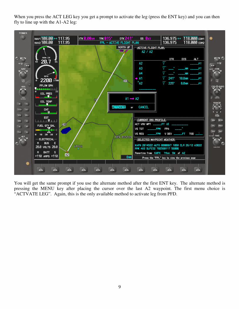
When you press the ACT LEG key you get a prompt to activate the leg (press the ENT key) and you can then
fly to line up with the A1-A2 leg:
You will get the same prompt if you use the alternate method after the first ENT key. The alternate method is
pressing the MENU key after placing the cursor over the last A2 waypoint. The first menu choice is
“ACTVATE LEG”. Again, this is the only available method to activate leg from PFD.

10
The A1 to A2 flight plan leg is now shown active. When the new XTK (Cross Track Error) reduces to 1 nm,
put the auto pilot in NAV mode, and the airplane will intercept the A1 to A2 course line outside of A1.

11
At this point you can navigate to A1 manually or let the autopilot intercept the inbound course to the A2-A1 leg:
If you are using the autopilot in NAV mode to intercept the A1 to A2 course line, there is no need to using OBS
mode prior to arriving at A1, the CSP. However, if you are manually lining up with the A1 to A2 course line,
you may find putting the PFD into OBS mode useful. This will provide a lead in line to follow into A1.

12
The aircraft is shown on the last flight plan leg, which is the first search track. If you had used OBS mode to
manually get on to the A1 to A2 course line before arriving at A1, turn off OBS mode before arriving at A2. If
left in OBS mode, the earlier flight plan legs defining the search perimeter will not be shown.

13
As you fly the first leg, note the required Heading you will need to fly to stay on the Course line to compensate
for wind. With the wind set to 010 at 16 knots in the simulator you would be flying a heading of 231 degrees to
track a course of 225. On the latest G1000 displays you can fly a desired Course track by selecting a heading
that puts the magenta “Current Track Bug” on the desired track or fly the desired Track on the MFD using the
TRK field on the MFD Navigation Status Bar (if selected for display):
NOTE: Remembering this heading as it will make flying later legs easier in the A1 to A2 direction (225 deg) to
maintain without a displayed course line. At the end of the first leg, make a 180 degree course reversal and fly
parallel to the first leg with a 0.5 NM offset into the grid. This is best done (in my experience) by setting the
MFD display to Track Up rather than North Up used in the simulator until now.
14
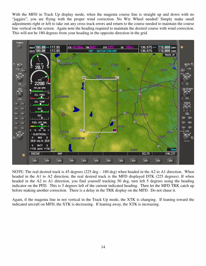
With the MFD in Track Up display mode, when the magenta course line is straight up and down with no
“jaggies”, you are flying with the proper wind correction. No Wiz Wheel needed! Simply make small
adjustments right or left to take out any cross track errors and return to the course needed to maintain the course
line vertical on the screen. Again note the heading required to maintain the desired course with wind correction.
This will not be 180 degrees from your heading in the opposite direction in the grid.
NOTE: The real desired track is 45 degrees (225 deg – 180 deg) when headed in the A2 to A1 direction. When
headed in the A1 to A2 direction, the real desired track is the MFD displayed DTK (225 degrees). If when
headed in the A2 to A1 direction, you find yourself tracking 50 deg, turn left 5 degrees using the heading
indicator on the PFD. This is 5 degrees left of the current indicated heading. Then let the MFD TRK catch up
before making another correction. There is a delay in the TRK display on the MFD. Do not chase it.
Again, if the magenta line in not vertical in the Track Up mode, the XTK is changing. If leaning toward the
indicated aircraft on MFD, the XTK is decreasing. If leaning away, the XTK is increasing.
15
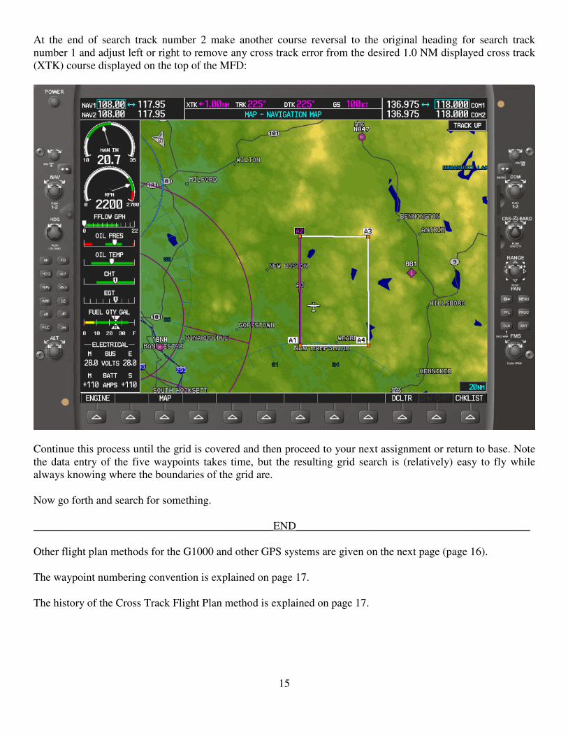
At the end of search track number 2 make another course reversal to the original heading for search track
number 1 and adjust left or right to remove any cross track error from the desired 1.0 NM displayed cross track
(XTK) course displayed on the top of the MFD:
Continue this process until the grid is covered and then proceed to your next assignment or return to base. Note
the data entry of the five waypoints takes time, but the resulting grid search is (relatively) easy to fly while
always knowing where the boundaries of the grid are.
Now go forth and search for something.
___________________________________________END__________________________________________
Other flight plan methods for the G1000 and other GPS systems are given on the next page (page 16).
The waypoint numbering convention is explained on page 17.
The history of the Cross Track Flight Plan method is explained on page 17.
16
OTHER METHODS FOR G1000 and OTHER GPSs:
If the transit from KCON to CSP cannot be Present Position direct to CSP, the simpler preferred method, there
are two other possible flight plans. i.e. KCON via waypoint X to A1, the CSP.
The first method: KCON > X > A1 > A2 > A3 > A4 > A1 > A2 When on the first A1 > A2 flight plan leg,
activate the last A1 > A2 leg; otherwise you will box the search area.
The second method is to split the above flight plan into two flight plans:
1st FPL: KCON > X > A1 > A2
2nd
FPL: A2 > A3 > A4 > A1 > A2 (This is the same flight plan as the simpler preferred method.)
When on the 1st FPL A1 > A2 leg, activate the 2
nd FPL from the flight plan catalog. The 2
nd FPL A1 to A2 leg
will automatically activate. The second method is preferred if the ingress route crosses through the search area.
The ingress route through the search area will be extinguished from the MFD map when the 2nd
FPL is
activated.
If a precise return to base routing from the search area is required, a separate return flight plan is required. The
Cross Track Flight Plan method will not work if the return routing is appended to any search flight plan
All the methods developed for the G1000 will work for all the Garmin 400 series and Garmin GTN series GPSs.
KLN94:
The simpler preferred method and the second alternate flight plan method will work for the KLN94. The first
alternate method will not work for the KLN94, because there is no ACTIVATE LEG function in the KLN94.
However, the simpler preferred method flight plan has to be in the flight plan catalog (not FPL 0). For the
KLN94 when the Present Position DIRECT TO CSP is used, the search perimeter is lost. However, activating a
new copy from the flight plan catalog, when on the last flight plan leg, will restore the search area perimeter.
The last leg will activate automatically.
KLN89:
These methods do not work for the KLN89. Only the active flight plan leg is displayed. Only the waypoints
defining prior and future legs are shown on the moving map.
Garmin GNS480 (optional): A1 > A2 > A3 > A4 > A1
Garmin GNS480 (optional) and Apollo GX series (mandatory): KCON > A1 > A2 > A3 > A4 > A1
Both units will extinguish the KCON > A1 leg from the moving map upon arriving at waypoint A1.
SUSPEND (GNS480) or HOLD (GX series) waypoint sequencing on the A1 > A2 leg. These units extinguish
flight plan legs flown or bypassed. Future legs are not extinguished. Both units can suspend waypoint
sequencing without going into OBS mod. The GX series does not permit DIRECT TO the very first waypoint
in a flight plan. That very first waypoint for the GX series can be any waypoint. When using the GNS480
trainer, leading the flight plan with the origin airport is preferred, because activating a flight plan in this trainer
auto positions the simulated aircraft to the first flight plan waypoint.

17
WAYPOINT NUMBERING CONVENTION:
The waypoint numbering convention was chosen for teaching purposes. Waypoint 0 is for construction
purposes, and is not used in the flight plan. Waypoint 1 is always the Commence Search Point (CSP).
Waypoint 2 is always the end of the first search track. Subsequent waypoints define the other corners of the
search area. For traditional US grids, waypoint 0 is not used, and waypoints 1, 2, 3, and 4 are defined by
latitude/longitude. Having a standard waypoint numbering system makes building flight plans easier. For
G1000, Garmin 400 series and GTN series, and the KLN94 GPSs, the flight plan is:
2 > 3 > 4 > 1 > 2
For the Garmin GNS480 and the Apollo GX series: airport > 1 > 2 > 3 > 4 > 1 The airport > 1 leg will
disappear from the moving map upon arriving at waypoint 1. This flight plan arrangement still allows going
present position to waypoint 1.
Waypoints are preceded by a letter or combinations of letters to make waypoints for different search flight plan
unique in the user waypoint database:
A2 > A3 > A4 > A1 > A2
B2 > B3 > B4 > B1 > B2
Z2 > Z3 > Z4 > Z1 > Z2 Experienced aircrews may develop their own waypoint naming or numbering convention. The above
numbering convention was established by Civil Air Patrol for teaching purposes.
HISTORY:
The 2005 version of this document was the spring board for the Cross Track Flight Plan method. Outside of NHWG Civil
Air Patrol, it was first used on Southeast watch by FLWG. Southeast watch search area perimeters were not simple
rectangular perimeters. On Atlantic side, the search perimeter was a polygon. On the Gulf of New Mexico side, the
search area was a parallelogram. The Cross Track Flight Plan method worked perfectly for these searches. Varying
search visibilities were encountered, and the ability to vary the track spacing dynamically was very useful.
Very few CAP pilots get to use CAP aircraft on long cross country flights. The result is that many Civil Air Patrol pilots
are not proficient in manipulating flight plans. Performing the Cross Track Flight Plan method for traditional US Grid
parallel grid searches keeps flight plan manipulation skills active. Even though, American Shield does not use the Cross
Track Flight Plan method, this method maintains most flight plan skills required by American Shield.
Since 2005, it was learned for most situations routing from the airport to the CSP (Commence Search Point) need not be
included in the stored flight plan. In most situations, it is sufficient to go Present Position DIRECT TO the CSP. When
arriving at the CSP, the temporary Present Position to CSP flight plan leg is removed from the moving map, and the
waypoint 4 to waypoint 1 (CSP) flight plan leg is restored to the moving map. This avoids having to put the waypoint 1
(CSP) to waypoint 2 leg in twice into the flight plan along with the origin airport. It is a real advantage when the airport
to CSP leg crosses through the search area. Upon arriving at the CSP, the airport to CSP leg is removed from the moving
map. The search area is not cluttered with a confusing flight plan line passing through it. If a precise multi waypoint
route from airport to the CSP is required as in Southeast watch, a separate ingress flight plan works better.
Experience training mission pilots, standardizing the waypoint numbering convention was found to be useful. Zero was
chosen for a build waypoint that will not appear in the flight plan, because a build waypoint is not needed if the waypoints
are defined by latitude and longitude. One is assigned to the CSP, because there will always be a CSP, waypoint 1. For
polygons, the number flight plan waypoints will vary according to number sides.