g u a r d e v o l u t i o n - kva diesel · g u a r d e v o l u t i o n operation manual this...
TRANSCRIPT

G U A R D E V O L U T I O N
OPERATION MANUAL
This manual is an addendum to the POWERFULL series generating set manual
CAUTION Carefully read this manual which is an addendum to the POWERFULL manual. If there are any doubts, even after having consulted the POWERFULL, engine and alternator manuals, contact a VISA technician or your nearest authorised dealer for assistance.
" GUARD EVOLUTION "
Visa S.p.A.Via Vallonto, 53 – 31043 Fontanelle (TV) POWERFULL manual addendum
112000000002-001-00 – 26/03/2008Printed in Italy – All rights reserved.
Page 1
GENERAL DESCRIPTION
Your generating set is equipped with the Guard Evolution - an advanced digital command, control and protection device projected to use the generating set in various operating modes. The manual version (base version) can be expanded by integrating software or hardware to create the following options:
Manual Function (base version)Automatic remote command Function [Autostart] (base version with activated software)Automatic Mains failure Function [AMF] (base version with integrated Hardware and activated software)Automatic Fuel Tank Filling Function (base version with integrated Hardware and activated software)Special Functions to integrate with Visa standard functions on request
This innovative device has the following characteristics:
The integration of engine and alternator protections, with signals and automatic stop in case of fault, in a single system able to analyse and compare the values of various engine and alternator parameters. In the automatic version, the protection is extended to the User system in case of fault with the Mains feed.
The electrical and engine parameters, as well as the generating set functions operating, and any warning or alarm messages are clearly communicated and seen by the technician on a large display screen. The warning and alarm messages are also pointed out visually and audibly through LED’s and acoustic signals respectively, that can be connected to a remote station. The Guard Evolution functions can be modified without having to substitute the entire control panel by simply programming the extra functions or installing the required software. The various standard functions are described in this manual. The device also allows for other function modes required for special needs. For further information contact our sales office at +39 0422 5091
" GUARD EVOLUTION "
Visa S.p.A.Via Vallonto, 53 – 31043 Fontanelle (TV) POWERFULL manual addendum
112000000002-001-00 – 26/03/2008Printed in Italy – All rights reserved.
Page 2
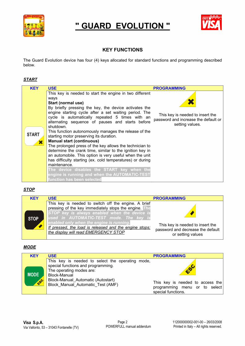
KEY FUNCTIONS
The Guard Evolution device has four (4) keys allocated for standard functions and programming described below.
START
KEY USE PROGRAMMINGThis key is needed to start the engine in two different waysStart (normal use)By briefly pressing the key, the device activates the engine starting cycle after a set waiting period. The cycle is automatically repeated 5 times with an alternating sequence of pauses and starts before shutdown.This function autonomously manages the release of the starting motor preserving its duration.Manual start (continuous)The prolonged press of the key allows the technician to determine the crank time, similar to the ignition key in an automobile. This option is very useful when the unit has difficulty starting (ex. cold temperatures) or duringmaintenance.The device disables the START key when the engine is running and when the AUTOMATIC-TEST function has been selected
This key is needed to insert the password and increase the default or
setting values.
STOP
KEY USE PROGRAMMINGThis key is needed to switch off the engine. A brief pressing of the key immediately stops the engine. The STOP key is always enabled when the device is used in AUTOMATIC-TEST mode. The key is enabled only when the engine is running. If pressed, the load is released and the engine stops; the display will read EMERGENCY STOP
This key is needed to insert the password and decrease the default
or setting values
MODE
KEY USE PROGRAMMINGThis key is needed to select the operating mode, special functions and programming.The operating modes are:Block-ManualBlock-Manual_Automatic (Autostart)Block_Manual_Automatic_Test (AMF) This key is needed to access the
programming menu or to select special functions.
" GUARD EVOLUTION "
Visa S.p.A.Via Vallonto, 53 – 31043 Fontanelle (TV) POWERFULL manual addendum
112000000002-001-00 – 26/03/2008Printed in Italy – All rights reserved.
Page 3
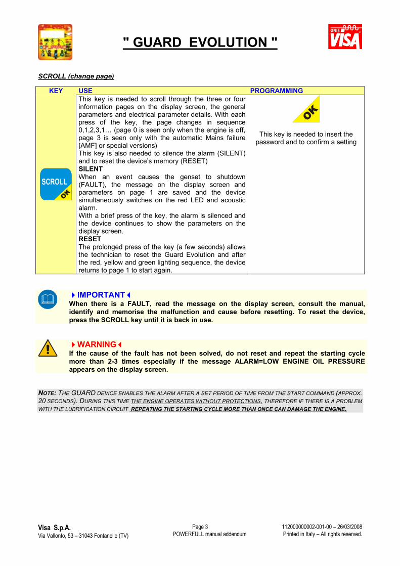
SCROLL (change page)
KEY USE PROGRAMMINGThis key is needed to scroll through the three or four information pages on the display screen, the general parameters and electrical parameter details. With each press of the key, the page changes in sequence 0,1,2,3,1… (page 0 is seen only when the engine is off, page 3 is seen only with the automatic Mains failure[AMF] or special versions)This key is also needed to silence the alarm (SILENT) and to reset the device’s memory (RESET)SILENTWhen an event causes the genset to shutdown (FAULT), the message on the display screen and parameters on page 1 are saved and the device simultaneously switches on the red LED and acoustic alarm. With a brief press of the key, the alarm is silenced and the device continues to show the parameters on the display screen.RESETThe prolonged press of the key (a few seconds) allows the technician to reset the Guard Evolution and after the red, yellow and green lighting sequence, the device returns to page 1 to start again.
This key is needed to insert the password and to confirm a setting
IMPORTANTWhen there is a FAULT, read the message on the display screen, consult the manual, identify and memorise the malfunction and cause before resetting. To reset the device, press the SCROLL key until it is back in use.
WARNINGIf the cause of the fault has not been solved, do not reset and repeat the starting cycle more than 2-3 times especially if the message ALARM=LOW ENGINE OIL PRESSURE appears on the display screen.
NOTE: THE GUARD DEVICE ENABLES THE ALARM AFTER A SET PERIOD OF TIME FROM THE START COMMAND (APPROX. 20 SECONDS). DURING THIS TIME THE ENGINE OPERATES WITHOUT PROTECTIONS, THEREFORE IF THERE IS A PROBLEM WITH THE LUBRIFICATION CIRCUIT REPEATING THE STARTING CYCLE MORE THAN ONCE CAN DAMAGE THE ENGINE.
" GUARD EVOLUTION "
Visa S.p.A.Via Vallonto, 53 – 31043 Fontanelle (TV) POWERFULL manual addendum
112000000002-001-00 – 26/03/2008Printed in Italy – All rights reserved.
Page 4
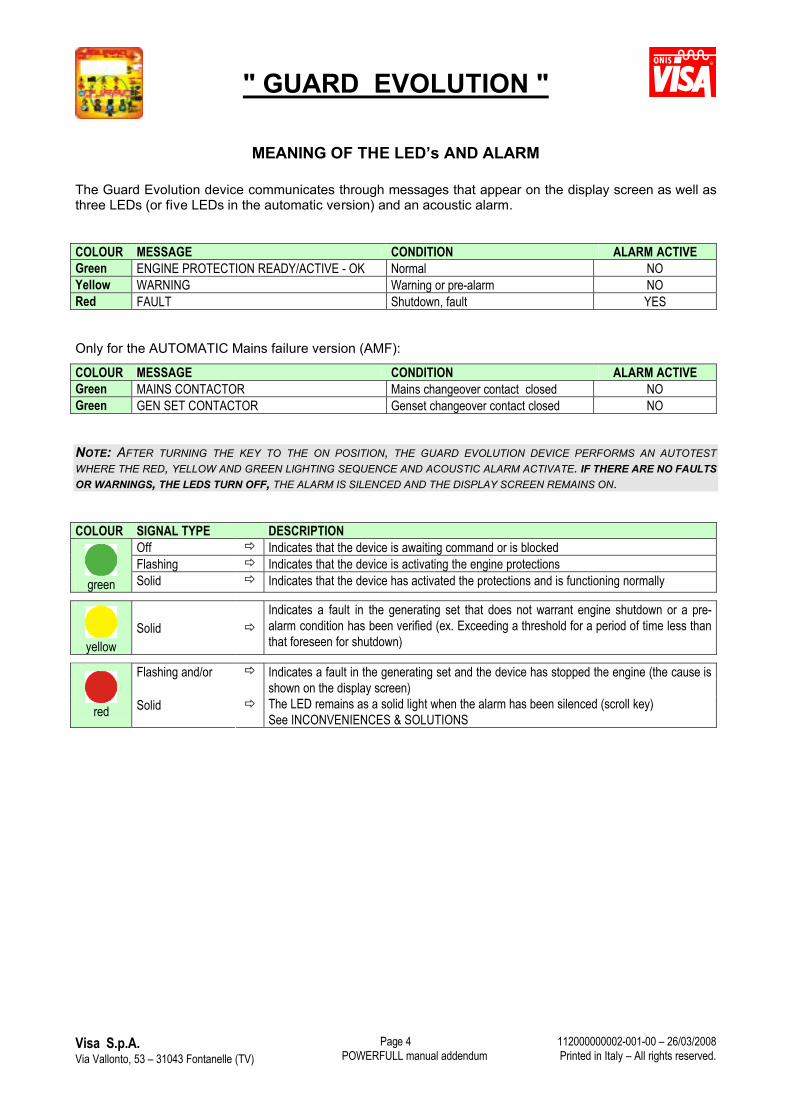
MEANING OF THE LED’s AND ALARM
The Guard Evolution device communicates through messages that appear on the display screen as well as three LEDs (or five LEDs in the automatic version) and an acoustic alarm.
COLOUR MESSAGE CONDITION ALARM ACTIVEGreen ENGINE PROTECTION READY/ACTIVE - OK Normal NOYellow WARNING Warning or pre-alarm NORed FAULT Shutdown, fault YES
Only for the AUTOMATIC Mains failure version (AMF):
COLOUR MESSAGE CONDITION ALARM ACTIVEGreen MAINS CONTACTOR Mains changeover contact closed NOGreen GEN SET CONTACTOR Genset changeover contact closed NO
NOTE: AFTER TURNING THE KEY TO THE ON POSITION, THE GUARD EVOLUTION DEVICE PERFORMS AN AUTOTEST WHERE THE RED, YELLOW AND GREEN LIGHTING SEQUENCE AND ACOUSTIC ALARM ACTIVATE. IF THERE ARE NO FAULTS OR WARNINGS, THE LEDS TURN OFF, THE ALARM IS SILENCED AND THE DISPLAY SCREEN REMAINS ON.
COLOUR SIGNAL TYPE DESCRIPTIONOff Indicates that the device is awaiting command or is blockedFlashing Indicates that the device is activating the engine protections
green Solid Indicates that the device has activated the protections and is functioning normally
yellowSolid
Indicates a fault in the generating set that does not warrant engine shutdown or a pre-alarm condition has been verified (ex. Exceeding a threshold for a period of time less than that foreseen for shutdown)
Flashing and/or
red Solid
Indicates a fault in the generating set and the device has stopped the engine (the cause is shown on the display screen)The LED remains as a solid light when the alarm has been silenced (scroll key)See INCONVENIENCES & SOLUTIONS
" GUARD EVOLUTION "
Visa S.p.A.Via Vallonto, 53 – 31043 Fontanelle (TV) POWERFULL manual addendum
112000000002-001-00 – 26/03/2008Printed in Italy – All rights reserved.
Page 5
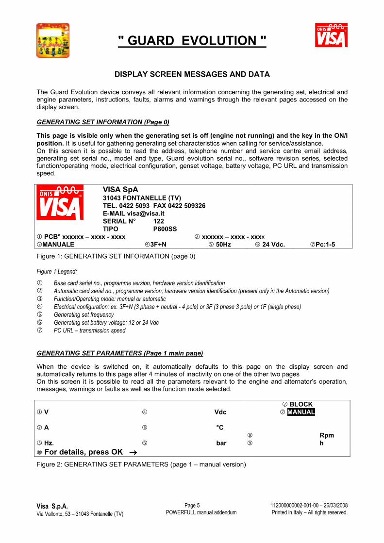
DISPLAY SCREEN MESSAGES AND DATA
The Guard Evolution device conveys all relevant information concerning the generating set, electrical andengine parameters, instructions, faults, alarms and warnings through the relevant pages accessed on the display screen.
GENERATING SET INFORMATION (Page 0)
This page is visible only when the generating set is off (engine not running) and the key in the ON/I position. It is useful for gathering generating set characteristics when calling for service/assistance. On this screen it is possible to read the address, telephone number and service centre email address, generating set serial no., model and type, Guard evolution serial no., software revision series, selected function/operating mode, electrical configuration, genset voltage, battery voltage, PC URL and transmissionspeed.
VISA SpA31043 FONTANELLE (TV)TEL. 0422 5093 FAX 0422 509326E-MAIL [email protected] N� 122TIPO P800SS
PCB� xxxxxx – xxxx - xxxx xxxxxx – xxxx - xxxxMANUALE 3F+N 50Hz 24 Vdc. Pc:1-5
Figure 1: GENERATING SET INFORMATION (page 0)
Figure 1 Legend:
Base card serial no., programme version, hardware version identification Automatic card serial no., programme version, hardware version identification (present only in the Automatic version) Function/Operating mode: manual or automatic Electrical configuration: ex. 3F+N (3 phase + neutral - 4 pole) or 3F (3 phase 3 pole) or 1F (single phase) Generating set frequency Generating set battery voltage: 12 or 24 Vdc PC URL – transmission speed
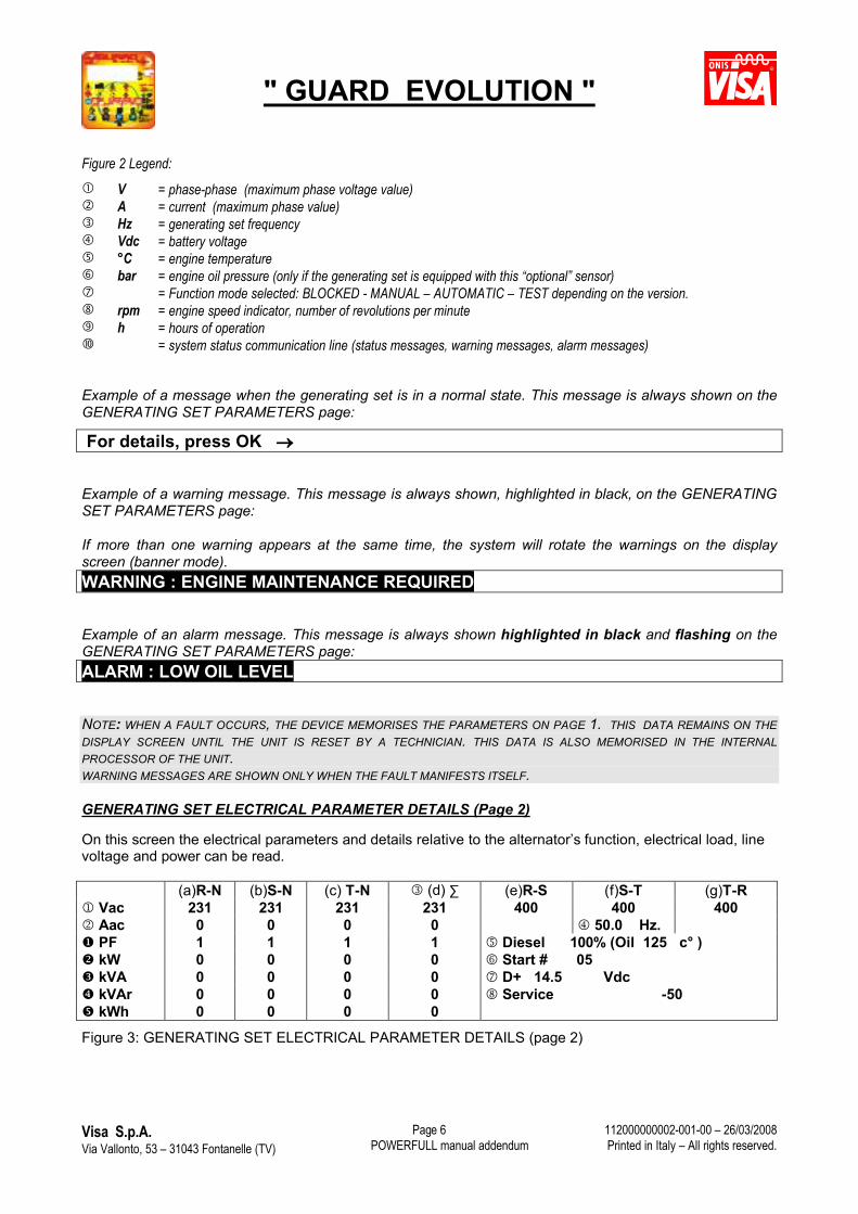
GENERATING SET PARAMETERS (Page 1 main page)
When the device is switched on, it automatically defaults to this page on the display screen and automatically returns to this page after 4 minutes of inactivity on one of the other two pagesOn this screen it is possible to read all the parameters relevant to the engine and alternator’s operation, messages, warnings or faults as well as the function mode selected.
BLOCK V Vdc MANUAL
A �C Rpm
Hz. bar h For details, press OK
Figure 2: GENERATING SET PARAMETERS (page 1 – manual version)
" GUARD EVOLUTION "
Visa S.p.A.Via Vallonto, 53 – 31043 Fontanelle (TV) POWERFULL manual addendum
112000000002-001-00 – 26/03/2008Printed in Italy – All rights reserved.
Page 6
Figure 2 Legend: V = phase-phase (maximum phase voltage value) A = current (maximum phase value) Hz = generating set frequency Vdc = battery voltage �C = engine temperature bar = engine oil pressure (only if the generating set is equipped with this “optional” sensor) = Function mode selected: BLOCKED - MANUAL – AUTOMATIC – TEST depending on the version. rpm = engine speed indicator, number of revolutions per minute h = hours of operation = system status communication line (status messages, warning messages, alarm messages)
Example of a message when the generating set is in a normal state. This message is always shown on the GENERATING SET PARAMETERS page:
For details, press OK
Example of a warning message. This message is always shown, highlighted in black, on the GENERATING SET PARAMETERS page: If more than one warning appears at the same time, the system will rotate the warnings on the display screen (banner mode).
WARNING : ENGINE MAINTENANCE REQUIRED
Example of an alarm message. This message is always shown highlighted in black and flashing on the GENERATING SET PARAMETERS page:ALARM : LOW OIL LEVEL
NOTE: WHEN A FAULT OCCURS, THE DEVICE MEMORISES THE PARAMETERS ON PAGE 1. THIS DATA REMAINS ON THE DISPLAY SCREEN UNTIL THE UNIT IS RESET BY A TECHNICIAN. THIS DATA IS ALSO MEMORISED IN THE INTERNAL PROCESSOR OF THE UNIT. WARNING MESSAGES ARE SHOWN ONLY WHEN THE FAULT MANIFESTS ITSELF.
GENERATING SET ELECTRICAL PARAMETER DETAILS (Page 2)
On this screen the electrical parameters and details relative to the alternator’s function, electrical load, line voltage and power can be read.
(a)R-N (b)S-N (c) T-N (d) ∑ (e)R-S (f)S-T (g)T-R Vac 231 231 231 231 400 400 400 Aac 0 0 0 0 50.0 Hz. PF 1 1 1 1 Diesel 100% (Oil 125 c� ) kW 0 0 0 0 Start # 05 kVA 0 0 0 0 D+ 14.5 Vdc kVAr 0 0 0 0 Service -50 kWh 0 0 0 0
Figure 3: GENERATING SET ELECTRICAL PARAMETER DETAILS (page 2)
" GUARD EVOLUTION "
Visa S.p.A.Via Vallonto, 53 – 31043 Fontanelle (TV) POWERFULL manual addendum
112000000002-001-00 – 26/03/2008Printed in Italy – All rights reserved.
Page 7
Figura 3 Legend: Vac = generated voltage (ref. Columns A - G the detailed value is read between phase – neutral and phase –
phase) Aac = delivered phase current (ref. Column A – C) PF = cos power factor of the electric load (ref. Column A – C) – the absolute value is indicated - kW = active power (ref. Column A – C) kVA = apparent power (ref. Column A – C) kVAr = apparent reactive power (ref. Column A – C ) kWh = energy produced (ref. Column A – C) ∑ = For the Vac, Aac and PF parameters, the value indicated is the mathematical average of the values in
columns A-B-C. For the kW, kVA, kVAr, kWh parameters – the value indicated is the sum of the values in columns A-B-
C. Hz = Generating set frequency Diesel/oil C� = fuel level % and engine oil temperature (optional) * Start = the number of starting tries effected D+ = alternator battery charger regulator voltage (parameter used only during the device’s verification) Service = Countdown – indicates how may hours of operation remain until scheduled maintenance
The measurements with the numbers highlighted in black are part of an optional package. * The fuel level in the tank and the engine oil temperature are functions that require optional sensors to be
mounted. In the case that both are requested, the Guard Evolution device will alternate the visualisation of each on the display screen.
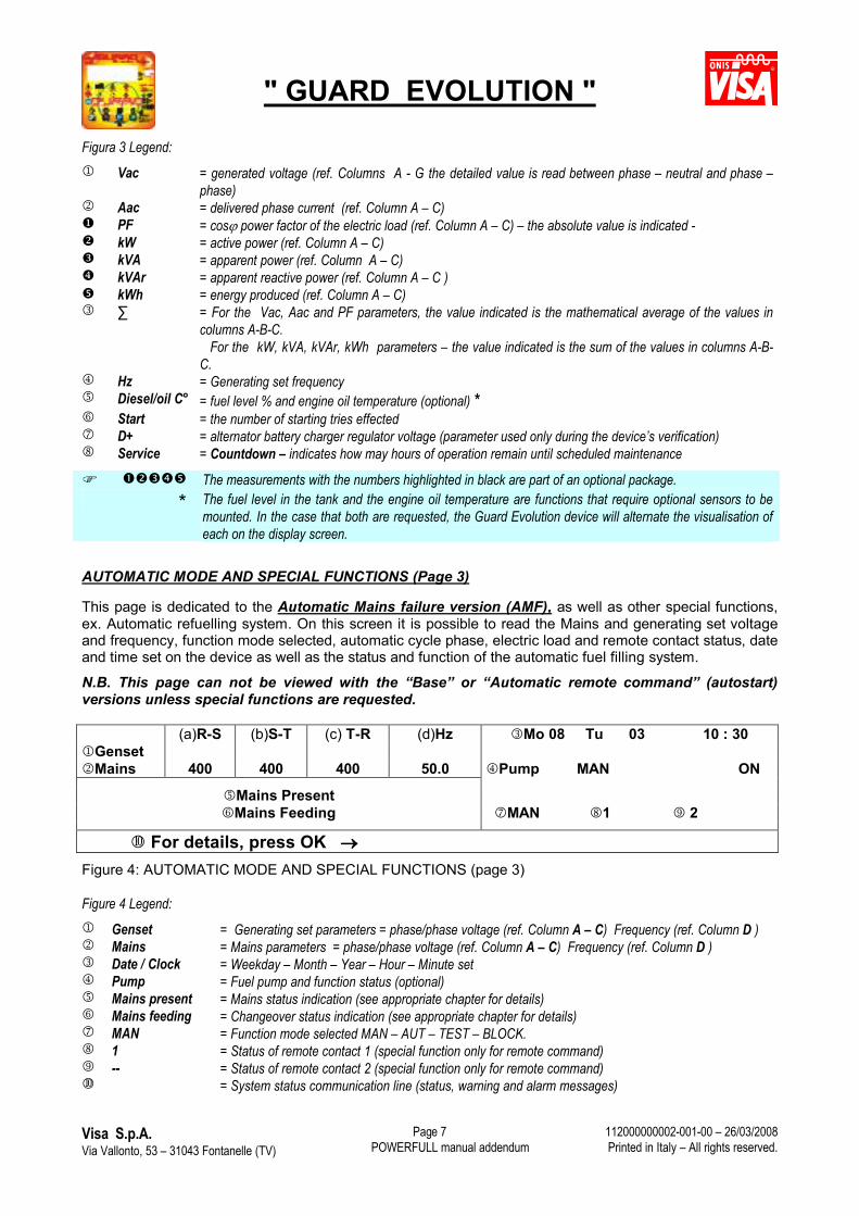
AUTOMATIC MODE AND SPECIAL FUNCTIONS (Page 3)
This page is dedicated to the Automatic Mains failure version (AMF), as well as other special functions, ex. Automatic refuelling system. On this screen it is possible to read the Mains and generating set voltage and frequency, function mode selected, automatic cycle phase, electric load and remote contact status, date and time set on the device as well as the status and function of the automatic fuel filling system.
N.B. This page can not be viewed with the “Base” or “Automatic remote command” (autostart) versions unless special functions are requested.
(a)R-S (b)S-T (c) T-R (d)Hz Mo 08 Tu 03 10 : 30GensetMains 400 400 400 50.0 Pump MAN ON
Mains PresentMains Feeding MAN 1 2
For details, press OK Figure 4: AUTOMATIC MODE AND SPECIAL FUNCTIONS (page 3)
Figure 4 Legend: Genset = Generating set parameters = phase/phase voltage (ref. Column A – C) Frequency (ref. Column D ) Mains = Mains parameters = phase/phase voltage (ref. Column A – C) Frequency (ref. Column D ) Date / Clock = Weekday – Month – Year – Hour – Minute set Pump = Fuel pump and function status (optional) Mains present = Mains status indication (see appropriate chapter for details) Mains feeding = Changeover status indication (see appropriate chapter for details) MAN = Function mode selected MAN – AUT – TEST – BLOCK. 1 = Status of remote contact 1 (special function only for remote command) -- = Status of remote contact 2 (special function only for remote command) = System status communication line (status, warning and alarm messages)
" GUARD EVOLUTION "
Visa S.p.A.Via Vallonto, 53 – 31043 Fontanelle (TV) POWERFULL manual addendum
112000000002-001-00 – 26/03/2008Printed in Italy – All rights reserved.
Page 8
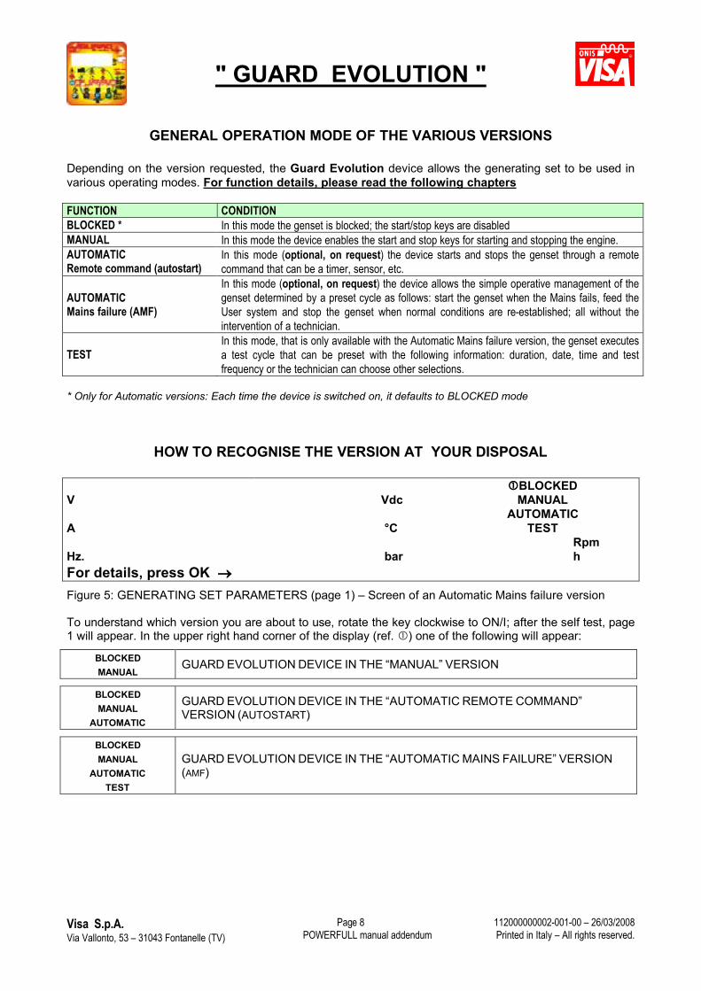
GENERAL OPERATION MODE OF THE VARIOUS VERSIONS
Depending on the version requested, the Guard Evolution device allows the generating set to be used in various operating modes. For function details, please read the following chapters
FUNCTION CONDITIONBLOCKED * In this mode the genset is blocked; the start/stop keys are disabledMANUAL In this mode the device enables the start and stop keys for starting and stopping the engine.AUTOMATIC Remote command (autostart)
In this mode (optional, on request) the device starts and stops the genset through a remote command that can be a timer, sensor, etc.
AUTOMATICMains failure (AMF)
In this mode (optional, on request) the device allows the simple operative management of the genset determined by a preset cycle as follows: start the genset when the Mains fails, feed the User system and stop the genset when normal conditions are re-established; all without the intervention of a technician.
TESTIn this mode, that is only available with the Automatic Mains failure version, the genset executes a test cycle that can be preset with the following information: duration, date, time and test frequency or the technician can choose other selections.
* Only for Automatic versions: Each time the device is switched on, it defaults to BLOCKED mode
HOW TO RECOGNISE THE VERSION AT YOUR DISPOSAL
BLOCKEDV Vdc MANUAL
AUTOMATICA �C TEST
Rpm Hz. bar hFor details, press OK
Figure 5: GENERATING SET PARAMETERS (page 1) – Screen of an Automatic Mains failure version
To understand which version you are about to use, rotate the key clockwise to ON/I; after the self test, page 1 will appear. In the upper right hand corner of the display (ref. ) one of the following will appear:
BLOCKEDMANUAL
GUARD EVOLUTION DEVICE IN THE “MANUAL” VERSION
BLOCKEDMANUAL
AUTOMATIC
GUARD EVOLUTION DEVICE IN THE “AUTOMATIC REMOTE COMMAND”VERSION (AUTOSTART)
BLOCKEDMANUAL
AUTOMATICTEST
GUARD EVOLUTION DEVICE IN THE “AUTOMATIC MAINS FAILURE” VERSION(AMF)
" GUARD EVOLUTION "
Visa S.p.A.Via Vallonto, 53 – 31043 Fontanelle (TV) POWERFULL manual addendum
112000000002-001-00 – 26/03/2008Printed in Italy – All rights reserved.
Page 9
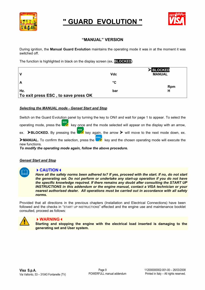
“MANUAL” VERSION
During ignition, the Manual Guard Evolution maintains the operating mode it was in at the moment it was switched off.
The function is highlighted in black on the display screen (ex. BLOCKED)
BLOCKEDV Vdc MANUAL
A �CRpm
Hz. bar HTo exit press ESC , to save press OK
Selecting the MANUAL mode - Genset Start and Stop
Switch on the Guard Evolution panel by turning the key to ON/I and wait for page 1 to appear. To select the
operating mode, press the key once and the mode selected will appear on the display with an arrow,
ex. BLOCKED. By pressing the key again, the arrow will move to the next mode down, ex.
MANUAL. To confirm the selection, press the key and the chosen operating mode will execute the new functions.To modify the operating mode again, follow the above procedure.
Genset Start and Stop
CAUTIONHave all the safety norms been adhered to? If yes, proceed with the start. If no, do not start the generating set. Do not perform or undertake any start-up operation if you do not have the specific knowledge required. If there remains any doubt after consulting the START UP INSTRUCTIONS in this addendum or the engine manual, contact a VISA technician or your nearest authorised dealer. All operations must be carried out in accordance with all safety norms.
Provided that all directions in the previous chapters (Installation and Electrical Connections) have been followed and the checks in “START UP INSTRUCTIONS” effected and the engine use and maintenance booklet consulted, proceed as follows:
WARNINGStarting and stopping the engine with the electrical load inserted is damaging to the generating set and User system.
" GUARD EVOLUTION "
Visa S.p.A.Via Vallonto, 53 – 31043 Fontanelle (TV) POWERFULL manual addendum
112000000002-001-00 – 26/03/2008Printed in Italy – All rights reserved.
Page 10
Genset Start
By pressing the (start) key, the device activates an acoustic signal. After a few seconds, the starting cycle begins. As soon as the engine is running, and after the preset time of 20 seconds, the green LED indicating ENGINE PROTECTION OK remains solid if everything is functioning normally.
Genset stop
By pressing the (stop) key the device shuts off the engine.For further details, see page ….
“AUTOMATIC” REMOTE COMMAND VERSION (AUTOSTART) (OPTIONAL)
In the Guard Evolution BASE version there is an option called “AUTOMATIC FUNCTION”.By connecting an apparatus that opens and closes a contact (ex. timer, manual selector switch, sensor, radio command, etc.) the device can automatically start and stop the genset, manage start times and authorisation (see User menu), as well as automatically shut off the generating set if any fault occurs.
The User system must be equipped with appropriate devices for the correct connection and releaseof the electrical load.
CAUTION Carefully read this addendum and if there remains any doubt, even after consulting the POWERFULL, engine and alternator manuals, contact a VISA technician or your nearest authorised dealer.
The default times of the AUTOMATIC remote command’s operating cycle are set by the manufacturer, some of these times can be modified through the User menu, see PARAMETERS LIST
WARNINGIn the Automatic versions (AMF and autostart), the technician must select the function mode desired each time he switches on the Guard Evolution device, because the device returns to the BLOCKED mode each time it is switched off.
SELECTING THE AUTOMATIC MODE
DANGERBefore selecting the AUTOMATIC function, make sure that the generating set is not able to start involuntarily (ex. the Mains fails and the genset starts or the remote contact is closed and the genset starts). Effect all controls and make sure that all the directions in Start Up Instructions have been followed.
Switch on the Guard Evolution panel by turning the key to ON/I and wait for the GENSET PARAMETERS
page to appear. Press the key once and the selected mode will appear on the display with an arrow,
" GUARD EVOLUTION "
Visa S.p.A.Via Vallonto, 53 – 31043 Fontanelle (TV) POWERFULL manual addendum
112000000002-001-00 – 26/03/2008Printed in Italy – All rights reserved.
Page 11
ex. BLOCKED. By pressing the key again, the arrow will move to the next mode down, ex.
AUTOMATIC. To confirm the selection, press the key and the chosen operating mode will execute the new functions. To modify the operating mode again, follow the above procedure.
It is possible to remove the key in the I/ON position
Note: The Guard Evolution device disables the automatic function and defaults to “blocked” every time an event causes the arrest of the generating set or the device’s power is interrupted.
BLOCKEDV Vdc MANUAL
AUTOMATICA �C
Rpm Hz. bar HTo exit press ESC, to save press OK
WARNINGStarting and stopping the engine with the electrical load inserted is damaging to the generating set and User system.
2 (n�terminal) 2 (n�terminal)
20 (n� terminal)Engine running
20 (n� terminal)Engine stopped
Figure 6: Remote command connection diagram
NOTE: The external contact must be a free contact. The distance of the cross section area between the generating set and remote contact should be 2.5 mm for a distance up to 200m (the contact’s circulating voltage is 12V or 24V D.C. depending on the engine’s electrical system). Important: the wiring cables must be isolated from possible fonts of electrical disturbance. For longer distances consult a Visa technician.
WARNINGWhen the AUTOMATIC mode is selected, the START key is disabled and the STOP key is enabled only when the engine is running. If pressed, the load is released and the engine stop is visualised on the display screen as EMERGENCY STOP. Otherwise, the emergency stop button is always enabled
REMOTE FAULT SIGNAL: The Guard Evolution device is equipped with a voltage signal (12V or 24V DC. positive ref. terminal 5 on terminal board M1) for a maximum load of 300 mA which can be used to feed an electric bell or something similar.)
" GUARD EVOLUTION "
Visa S.p.A.Via Vallonto, 53 – 31043 Fontanelle (TV) POWERFULL manual addendum
112000000002-001-00 – 26/03/2008Printed in Italy – All rights reserved.
Page 12
(In special versions this output may not be available or be used for another purpose)
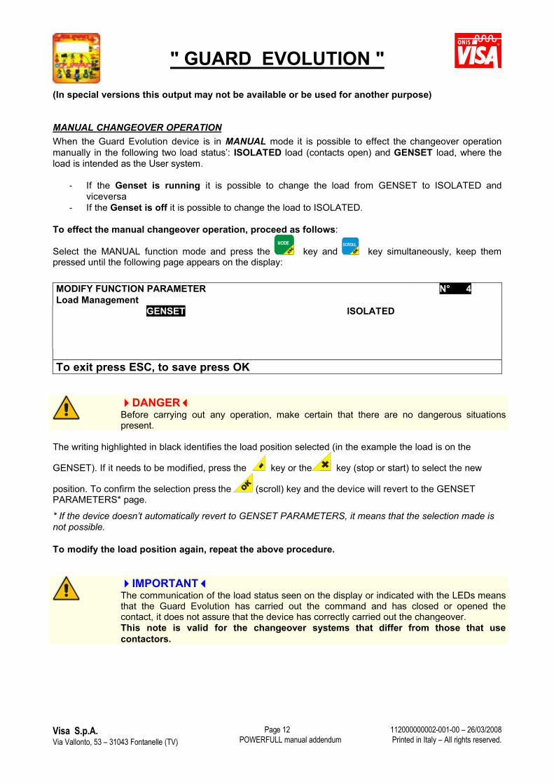
MANUAL CHANGEOVER OPERATION When the Guard Evolution device is in MANUAL mode it is possible to effect the changeover operation manually in the following two load status’: ISOLATED load (contacts open) and GENSET load, where the load is intended as the User system.
- If the Genset is running it is possible to change the load from GENSET to ISOLATED andviceversa
- If the Genset is off it is possible to change the load to ISOLATED.
To effect the manual changeover operation, proceed as follows:
Select the MANUAL function mode and press the key and key simultaneously, keep them pressed until the following page appears on the display:
MODIFY FUNCTION PARAMETER N� 4Load Management
GENSET ISOLATED
To exit press ESC, to save press OK
DANGERBefore carrying out any operation, make certain that there are no dangerous situationspresent.
The writing highlighted in black identifies the load position selected (in the example the load is on the
GENSET). If it needs to be modified, press the key or the key (stop or start) to select the new
position. To confirm the selection press the (scroll) key and the device will revert to the GENSET PARAMETERS* page.
* If the device doesn’t automatically revert to GENSET PARAMETERS, it means that the selection made is not possible.
To modify the load position again, repeat the above procedure.
IMPORTANTThe communication of the load status seen on the display or indicated with the LEDs means that the Guard Evolution has carried out the command and has closed or opened the contact, it does not assure that the device has correctly carried out the changeover.This note is valid for the changeover systems that differ from those that use contactors.
" GUARD EVOLUTION "
Visa S.p.A.Via Vallonto, 53 – 31043 Fontanelle (TV) POWERFULL manual addendum
112000000002-001-00 – 26/03/2008Printed in Italy – All rights reserved.
Page 13
“AUTOMATIC” MAINS FAILURE VERSION (AMF) (OPTIONAL)
The Guard Evolution AMF version (Mains isolated) allows the simple operative management of the generating set determined by the following preset cycle: start the genset when the Mains fails, feed the User system and stop the genset when normal conditions are re-established; all without the intervention of a technician. It is also possible to use the generating set in the manual, test and blocked modes.
NOTE: THE AUTOMATIC MODE SHOULD BE SELECTED TO MAKE THE GENSET WORK IN STAND-BY FOR EMERGENCIES.
CAUTIONCarefully read this addendum and if there remains any doubt, even after consulting the POWERFULL, engine and alternator manuals, contact a VISA technician or you nearestauthorised dealer.
The standard generating set equipped with the Guard Evolution Automatic (AMF) panel conforms to international standards that foresee the command logic and magneto-thermal switch mounted in the panel on board the genset, while the changeover switch (ATS - TLGR panel) is supplied in a separate case on request.
WARNING If the ATS panel has not been requested, the User system must be equipped with appropriate devices for the correct insertion and release of the electric load that corresponds to the norms and assures that the generating set operates exclusively with the MAINS ISOLATED.
IMPORTANTStarting and stopping the engine with the electrical load inserted is damaging to the generating set and User system.
CAUTIONOnly trained personnel should use the automatic generating set
" GUARD EVOLUTION "
Visa S.p.A.Via Vallonto, 53 – 31043 Fontanelle (TV) POWERFULL manual addendum
112000000002-001-00 – 26/03/2008Printed in Italy – All rights reserved.
Page 14
The electronic card (motherboard) can be programmed to operate in four different modes:
FUNCTION CONDITIONBLOCKED In this mode the genset is blocked; the start/stop keys are disabledMANUAL In this mode the device enables the start and stop keys for starting and stopping the engine.
AUTOMATICIn this mode (optional, on request) the device allows the simple operative management of the generating set determined by the following preset cycle: start the genset when the Mains fails, feed the User system, stop the genset when normal conditions are re-established; all without the intervention of a technician.
TEST In this mode the genset executes a test cycle that can be preset with the following information: duration, date, time and test frequency or the technician can choose other selections.
How to select the function mode is described on page …
DANGERThe transition from one mode to another can involuntarily start the engine or affect the Mains and generating set contactors. It is imperative that before any operation is effected, to ascertain there are no dangerous conditions present.
FUNCTION MODE DESCRIPTIONS
BLOCK When the Guard Evolution device is in BLOCK mode, the Start and Stop commands as well as the external commands like remote contact, special functions and software commands are not operative. However, Mode and Scroll remain active and therefore it is possible to select other modes or visualise the various pages. If the Mains fails, the command of the Mains contact remains closed.
Only in this mode is it possible to enter into programming.
Note: If the BLOCK mode has been selected and the Mains fails, the generating set will not start. The User system will be fed depending if the Mains is present or not.
IMPORTANTIf the device is not powered due to a wrong turn of the key or the battery(ies) being disconnected, it will enter into BLOCK mode when power returns.
MANUAL When the Guard Evolution panel is in MANUAL mode it is possible to start or stop the generating set using the START and STOP keys (see page 02 for key functions ). It is also possible to manually turn the Mains/Genset changeover switch in this mode by following the procedure below
Note: If, for example, the generating set is in MANUAL mode with the Mains contactor inserted and the Mains voltage present the contactor remains closed (User system fed by the Mains). But when the Mains fails and the contactor opens, the User system is not fed despite the fact the generating set is running because the genset contactor does not automatically close and therefore the User system is not fed.
" GUARD EVOLUTION "
Visa S.p.A.Via Vallonto, 53 – 31043 Fontanelle (TV) POWERFULL manual addendum
112000000002-001-00 – 26/03/2008Printed in Italy – All rights reserved.
Page 15
MANUAL CHANGEOVER OPERATION When the Guard Evolution device is in MANUAL mode it is possible to effect the changeover operation manually in the following three load status’: MAINS load, ISOLATED load (contacts open) and GENSET load, where the load is intended as the User system.
- Whether the Mains voltage is present or not and the Genset is running it is possible to change the load over from the MAINS onto the GENSET or ISOLATED and vice versa
- If the Mains voltage is present and the Genset is off it is possible to change the load from the MAINS onto ISOLATED.
To effect the manual changeover operation, proceed as follows:
Select the MANUAL function mode and press the and keys simultaneously, keep them pressed until the following page appears on the display:
MODIFY FUNCTION PARAMETER N� 4Load Management
MAINS ISOLATED
GENSET
To exit press ESC, to save press OK
DANGERBefore carrying out any operation, make certain that there are no dangerous situations present.
The writing highlighted in black identifies the load position selected (in the example the load is on the
MAINS). If it needs to be modified, press the key or the key (stop or start) to select the new
position. To confirm the selection press the (scroll) key and the device will revert to the GENSET PARAMETERS* page.
* If the device doesn’t automatically revert to GENSET PARAMETERS, it means that the selection made is not possible.
To modify the load position again, repeat the above procedure.
IMPORTANTThe communication of the load status seen on the display or indicated with the LEDs means that the Guard Evolution has carried out the command and has closed or opened the contact, it does not assure that the device has correctly carried out the changeover.This note is valid for the changeover systems that differ from those that use contactors.
AUTOMATIC
When the Guard Evolution device is in AUTOMATIC mode, the generating set operates according to a preset cycle. The details of the cycle are found in the automatic mode and special functions page and each phase of the automatic cycle, load status, Mains faults and relative parameters are seen in the communication line. Some of the parameter times can be modified by the User (see page).
" GUARD EVOLUTION "
Visa S.p.A.Via Vallonto, 53 – 31043 Fontanelle (TV) POWERFULL manual addendum
112000000002-001-00 – 26/03/2008Printed in Italy – All rights reserved.
Page 16
The operating logic is set with the advantage that allows the User system to be fed with the Mains in case the generating set or Guard Evolution fails or shuts off. The latter, nonetheless, enables the contact to close on the Mains if it fails.
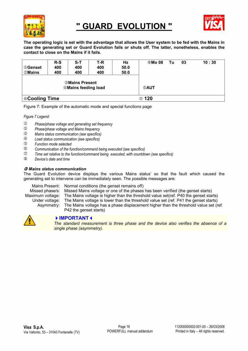
R-S S-T T-R Hz Mo 08 Tu 03 10 : 30Genset 400 400 400 50.0Mains 400 400 400 50.0
Mains PresentMains feeding load AUT
Cooling Time 120Figure 7: Example of the automatic mode and special functions page
Figure 7 Legend: Phase/phase voltage and generating set frequency Phase/phase voltage and Mains frequency Mains status communication (see specifics) Load status communication (see specifics) Function mode selected Communication of the function/command being executed (see specifics) Time set relative to the function/command being executed, with countdown (see specifics) Device’s date and time
Mains status communication The Guard Evolution device displays the various Mains status’ so that the fault which caused the generating set to intervene can be immediately seen. The possible messages are:
Mains Present: Normal conditions (the genset remains off)Missed phase/s: Missed Mains voltage or one of the phases has been verified (the genset starts)
Maximum voltage: The Mains voltage is higher than the threshold value set(ref. P40 the genset starts) Under voltage: The Mains voltage is lower than the threshold value set (ref. P41 the genset starts)
Asymmetry: The Mains voltage has a phase displacement higher than the threshold value set (ref. P42 the genset starts)
IMPORTANTThe standard measurement is three phase and the device also verifies the absence of a single phase (asymmetry).
" GUARD EVOLUTION "
Visa S.p.A.Via Vallonto, 53 – 31043 Fontanelle (TV) POWERFULL manual addendum
112000000002-001-00 – 26/03/2008Printed in Italy – All rights reserved.
Page 17
Load status communication The Guard Evolution device visualises the various load status’ (User system), referring to the commutationposition, so that the source feeding the User system can be immediately viewed. The possible messages are:
Mains feeding load:
Normal conditions when the Mains is present. The contact that feeds the User system from the Mains is closed; the green LED on the panel remains on which corresponds to MAINS CONTACTOR
Isolated load: Condition when the User system is isolated, this state is present when the ATS changeover is done manually; the green LEDs on the panel (Mains Contactor andGenset Contactor) remain off
Genset feeding load:
Normal conditions when the Mains is missing and the generating set is running. The contact that feeds the User system from the genset is closed; the green LED on the panel remains on which corresponds to GENSET CONTACTOR
IMPORTANTThe load status communication seen on the display or from the LEDs indicates that the Guard Evolution device has executed the command to open or close the contact. It does not assure that the changeover switch device has physically executed the manoeuvre. This note is valid for changeover switch systems different from those that use contactors.
Communication of the function/command being executed In the communication line the automatic generating set function/command sequence is seen. The messages are:
After a Mains failure has occurred, the following messages appear:Delay start D+ Glow plugs Inserted Starting motor inserted Engine running, protections excluded Delay genset insertion.
After the Mains has returned to within normal parameters, the following messages appear:Delay commutation Cooling time Engine stop For details press the SCROLL key
Time set relative to the function/command being executed, with countdown The functions/commands described in point have specific times (see Parameters list = P) shown through a countdown with the purpose of pointing out how much time remains until the function has been completed. When the countdown is finished, the next command appears with its respective countdown time.
AUTOMATIC CYCLE DESCRIPTION This paragraph describes the standard sequence of an automatic cycle with references to parameters and times set by the manufacturer.
After the Mains has failed and after a set waiting time (ref. P43+P21=10s.+0) the genset is started, as soon as the engine and alternator have reached the appropriate speeds, (the delay genset insertion time is activated ref.P22 = 20s) after this time has expired the load is transferred and therefore fed by the genset, which is in operation, for the entire duration of the Mains failure.At the return of the Mains , the genset continues to operate for a time defined by the Mains re-entry delay (ref. P44 = 10s) after this time elapses and the value is remains constant, commutator delay kicks in (P23=60s), after which the load is transferred and therefore fed by the Mains. The genset then automatically shuts off after it has finished cooling down (ref. P24= 120s running without load) and is ready to intervene once more.
" GUARD EVOLUTION "
Visa S.p.A.Via Vallonto, 53 – 31043 Fontanelle (TV) POWERFULL manual addendum
112000000002-001-00 – 26/03/2008Printed in Italy – All rights reserved.
Page 18
Note: The Mains fails when the voltage increases or decreases under/above the maximum/minimum threshold set (P40 and P41) or an asymmetry is revealed (P42 missed phase). The phenomenon must last for the established time set out in parameter P43 (Mains over-voltage threshold delay). See paragraph MAINS STATUS COMMUNICATION. The engine starting cycle is automatically repeated 5 times (it can be set for a maximum of 10 starts). So as not to damage the starting motor, the device pauses between each attempt before giving a fault for missed start. In generating sets equipped with pre-chamber engines (small power) the starting cycle is preceded by glow plug ignition time of 11 seconds. The time it takes for the engine to get up to speed depends on its dimensions and characteristics and can take anywhere from 5 to 20 seconds. The device considers the engine started when the alternator battery charger signal reaches the set value or when the frequency of the main genset alternator has exceeded 20Hz. It is unadvisable to set a time less than 10 seconds in P22 . The device controls the correct operation of the genset and provides engine protection with automatic stop if anomalies were to occur during operation. See chapter INCONVENIENCES & SOLUTIONS. Note: If the engine stops, the Guard Evolution device closes the commutation contact on the Mains, allowing it to feed the User system as soon as it gets back on line; the protections set on the P40 – P41 – P42 thresholds are deactivated/disabled. The device counts the time it takes for the Mains to re-enter as soon as the voltage values have been stable for at least 60 seconds; this is to avoid the continuous manoeuvre of the changeover switch between genset and Mains and vice versa due to the possible Mains voltage value fluctuations The Mains presence refers to the voltage re-entry or asymmetry value of the threshold foreseen. The hysteresis re-entry value for both checks is 4%. Ex. Maximum Mains voltage threshold value is 435V (for Mains at 400V). The device considers the voltage within the threshold when the value is less than 417.6V. If during cooling time, the Mains fails again, the device automatically transfers the load to the genset again. NOTE: When the AUTOMATIC mode is selected, the START key is disabled and the STOP key enabled only with the engine running. If pressed, the load is released and the engine stop is seen as EMERGENCY STOP on the display, while the emergency stop button is always enabled It is possible to remove the key even in the I/ON position.
TEST
The Guard Evolution device can execute the following TESTS
Manual test: The technician selects the test modeAutomatic test w/o load: By enabling the automatic test function without load through parameters P46,
P47 and P48 on the User menu, it is possible to set the beginning and end times and daily, weekly or monthly cycle.
Automatic test w/load: By enabling P45 as well, the automatic test is effected with load
WARNING When the TEST mode is selected, the generating set’s engine starts immediately. It is therefore imperative to ascertain that there are no dangerous situations present before selecting this function.
Manual Test When the TEST mode is selected, the acoustic alarm sounds and after a few seconds the starting cycle begins. The generating set starts running and remains running for the entire period that the TEST mode is selected. The commutation and possible load is passed to the genset only if the Mains fails. When the Mains re-enters within the values set, the changeover of the load goes back to the Mains. During the Test cycle the alarms are enabled and if a fault occurs the generating set stops.
" GUARD EVOLUTION "
Visa S.p.A.Via Vallonto, 53 – 31043 Fontanelle (TV) POWERFULL manual addendum
112000000002-001-00 – 26/03/2008Printed in Italy – All rights reserved.
Page 19
Note: This mode allows the technician to effect a genset test w/o load, without interfering with the User system being fed.
The test is done to make sure that the generating set is operating correctly and its aim is to prevent probable inefficiencies. It is very important that the test is carried out according to how it is described in checks procedure (see Powerfull manual). However, the necessity to test the generating set with load periodically should be considered. Manual Test execution (with the Mains present) Select the TEST mode. The generating set starts, let the genset run for at least 10 minutes. If the Guard Evolution device does not detect an anomaly (Warning or Fault) and there is are no problems with the generating set (engine, alternator, other parts), then the test is successful. To terminate the manual test, select the AUTOMATIC mode and the genset will shut off.If the MANUAL mode remains selected, the genset will continue operating.
Automatic Test (with and without load) By enabling parameter P46 (Enable automatic test), the Guard Evolution device has the possibility to effect a periodic test that is executed automatically and based on a pre-set cycle that can be daily, monthly or weekly.The time of the test needs to be set; parameter 47 establishes the time the test begins and parameter 48 establishes the time the test ends.Example of a preset cycle: Weekly cycle beginning Monday at 09:00 – 09:10 for a duration of 10 minutes
At the day and time established, an acoustic signal sounds before the genset starting cycle begins. After the start, the generating set is made to run for a pre-established time (without interfering with the way the User system is powered). At the end of the pre-established time the engine is stopped. By enabling parameter 045 (enable TEST with load) the Test is carried out with load on the generating set.
If during the test the Mains fails, the load is passed to the generating set as if it was in automatic mode and it carries out all the related functions according to the automatic cycle. During the Test function the alarms are enabled, if an anomaly occurs with the generating set the Fault or Warning message is seen on the display.
Note: This mode allows the generating set’s efficiency to be tried automatically without interfering with feeding the User system.
IMPORTANTThe test verifies that the generating set is functioning correctly and its purpose is to signal possible problems. This, however, does not exclude the maintenance technician from his obligation to directly check and control the generating set and take note of any preliminary signals. It is very important that the test is carried out according to how it is described in checks procedure (see Powerfull manual)
Note: The automatic test function is never enabled by the manufacturer The setting of this function is left solely to the discretion of the User
The periodic test is effected when the electronic card is in Automatic mode and the AUTOMATIC TEST mode has been enabled according to the procedures described in MODIFY PARAMETERS.
" GUARD EVOLUTION "
Visa S.p.A.Via Vallonto, 53 – 31043 Fontanelle (TV) POWERFULL manual addendum
112000000002-001-00 – 26/03/2008Printed in Italy – All rights reserved.
Page 20
SELECTING THE AUTOMATIC MODE
The AUTOMATIC remote command (autostart) function’s operating cycle is dependent on the standard times (default) set by the manufacturer, that can be modified with the User menu. See PARAMETERS LIST.
DANGERBefore selecting the AUTOMATIC function, make sure that the genset can not start involuntarily (ex. the Mains fails and the genset starts or the remote contact is closed and the genset starts). Effect all controls and make sure that all directions in Start Up Instructions have been followed.
Switch on the Guard Evolution device by turning the key to ON/I and wait for the GENSET PARAMETERS
page to appear. Press the key once and the mode selected will appear on the display with an arrow,
ex. BLOCKED. By pressing the key again, the arrow will move to the next mode down, ex.
AUTOMATIC. To confirm the selection, press the key and the chosen operating mode will execute the new functions. If the Mains is present, the genset will remain off and await to intervene only if the Mains fails.
It is possible to remove the key in the I/ON position
To modify the operating mode again, follow the above procedure.
IMPORTANTThe Guard Evolution device disables the automatic function and defaults to “blocked” every time an event provokes the arrest of the generating set or the device’s feed is interrupted
BLOCKV Vdc MANUAL
AUTOMATICA �C TEST
Rpm Hz. bar HTo exit press ESC, to save press OK Figure 8: Example of the Automatic mode and special functions page with automatic mode selected.
NOTE: When the AUTOMATIC mode is selected, the START key is disabled and the STOP key is always enabled if the device is in the AUTOMATIC remote command mode with the engine running. If pressed, the load is released and the engine stop is seen as EMERGENCY STOP on the display. It is possible to remove the key even in the I/ON position.
" GUARD EVOLUTION "
Visa S.p.A.Via Vallonto, 53 – 31043 Fontanelle (TV) POWERFULL manual addendum
112000000002-001-00 – 26/03/2008Printed in Italy – All rights reserved.
Page 21
MAINS/GENSET COMMUTATION COMMAND OUTPUT: The Guard Evolution device in the AMF version is equipped with the Mains/Genset commutation command contacts as follows: 01 Mains Contact N.C. 5A 250V.01 Genset Contact N.A. 5A 250V.
REMOTE CUMULATIVE ALARM: The Guard Evolution device in the AMF version, is equipped with the following cumulative signal, supplied as a clean contact to exchange load 5A max. 250V. N.C. (this can be used for an acoustic signal or similar).* The contact activates each time that the device detects a Fault or Warning that is permanent.
" GUARD EVOLUTION "
Visa S.p.A.Via Vallonto, 53 – 31043 Fontanelle (TV) POWERFULL manual addendum
112000000002-001-00 – 26/03/2008Printed in Italy – All rights reserved.
Page 22
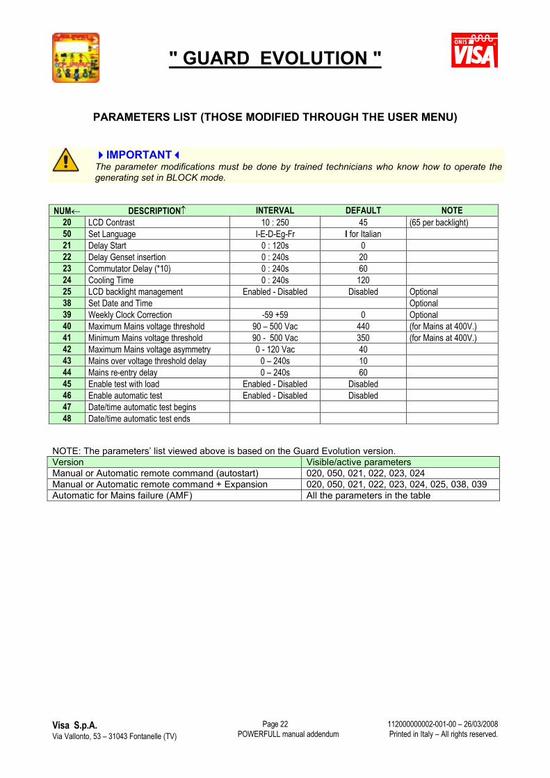
PARAMETERS LIST (THOSE MODIFIED THROUGH THE USER MENU)
IMPORTANTThe parameter modifications must be done by trained technicians who know how to operate the generating set in BLOCK mode.
NUM DESCRIPTION INTERVAL DEFAULT NOTE20 LCD Contrast 10 : 250 45 (65 per backlight)50 Set Language I-E-D-Eg-Fr I for Italian21 Delay Start 0 : 120s 022 Delay Genset insertion 0 : 240s 2023 Commutator Delay (*10) 0 : 240s 6024 Cooling Time 0 : 240s 12025 LCD backlight management Enabled - Disabled Disabled Optional38 Set Date and Time Optional39 Weekly Clock Correction -59 +59 0 Optional40 Maximum Mains voltage threshold 90 – 500 Vac 440 (for Mains at 400V.)41 Minimum Mains voltage threshold 90 - 500 Vac 350 (for Mains at 400V.)42 Maximum Mains voltage asymmetry 0 - 120 Vac 4043 Mains over voltage threshold delay 0 – 240s 1044 Mains re-entry delay 0 – 240s 6045 Enable test with load Enabled - Disabled Disabled46 Enable automatic test Enabled - Disabled Disabled47 Date/time automatic test begins48 Date/time automatic test ends
NOTE: The parameters’ list viewed above is based on the Guard Evolution version.Version Visible/active parametersManual or Automatic remote command (autostart) 020, 050, 021, 022, 023, 024Manual or Automatic remote command + Expansion 020, 050, 021, 022, 023, 024, 025, 038, 039Automatic for Mains failure (AMF) All the parameters in the table
" GUARD EVOLUTION "
Visa S.p.A.Via Vallonto, 53 – 31043 Fontanelle (TV) POWERFULL manual addendum
112000000002-001-00 – 26/03/2008Printed in Italy – All rights reserved.
Page 23
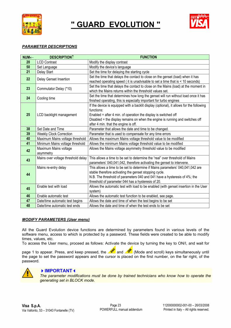
PARAMETER DESCRIPTIONS
NUM DESCRIPTION FUNCTION20 LCD Contrast Modify the display contrast50 Set Language Modify the device’s language 21 Delay Start Set the time for delaying the starting cycle
22 Delay Genset Insertion Set the time that delays the contact to close on the genset (load) when it has reached operating speed ( it is unadvisable to set a time that is < 10 seconds)
23 Commutator Delay (*10) Set the time that delays the contact to close on the Mains (load) at the moment in which the Mains returns within the threshold values set.
24 Cooling time Set the time that determines how long the genset will run without load once it has finished operating, this is especially important for turbo engines
25 LCD backlight management
If the device is equipped with a backlit display (optional), it allows for the following functions:Enabled = after 4 min. of operation the display is switched offDisabled = the display remains on when the engine is running and switches off after 4 min. that the engine is off.
38 Set Date and Time Parameter that allows the date and time to be changed.39 Weekly Clock Correction Parameter that is used to compensate for any time errors40 Maximum Mains voltage threshold Allows the maximum Mains voltage threshold value to be modified41 Minimum Mains voltage threshold Allows the minimum Mains voltage threshold value to be modified
42 Maximum Mains voltage asymmetry
Allows the Mains voltage asymmetry threshold value to be modified
43 Mains over voltage threshold delay This allows a time to be set to determine the “real” over threshold of Mains parameters’ 040,041,042, therefore activating the genset to intervene.
44Mains re-entry delay This allows a time to be set to determine if Mains parameters’ 040,041,042 are
stable therefore activating the genset stopping cycle. N.B. The threshold of parameters 040 and 041 have a hysteresis of 4%; the threshold of parameter 044 has a hysteresis of 20.
45 Enable test with load Allows the automatic test with load to be enabled (with genset insertion in the User system)
46 Enable automatic test Allows the automatic test function to be enabled, see page.47 Date/time automatic test begins Allows the date and time of when the test begins to be set48 Date/time automatic test ends Allows the date and time of when the test ends to be set
MODIFY PARAMETERS (User menu)
All the Guard Evolution device functions are determined by parameters found in various levels of the software menu, access to which is protected by a password. These fields were created to be able to modify times, values, etc. To access the User menu, proceed as follows: Activate the device by turning the key to ON/I, and wait for
page 1 to appear. Press, and keep pressed, the and (Mode and scroll) keys simultaneously until the page to set the password appears and the cursor is placed on the first number, on the far right, of the password.
IMPORTANTThe parameter modifications must be done by trained technicians who know how to operate the generating set in BLOCK mode.
" GUARD EVOLUTION "
Visa S.p.A.Via Vallonto, 53 – 31043 Fontanelle (TV) POWERFULL manual addendum
112000000002-001-00 – 26/03/2008Printed in Italy – All rights reserved.
Page 24
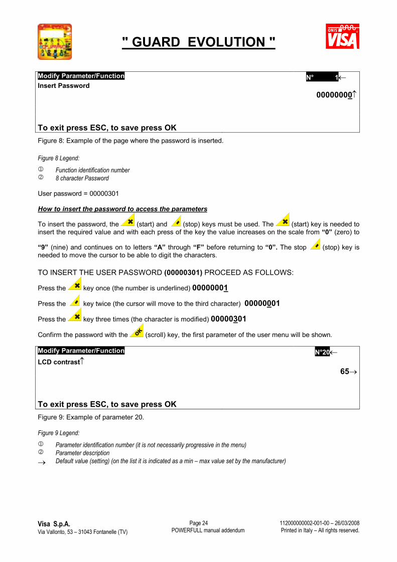
Modify Parameter/Function N� 1Insert Password
00000000
To exit press ESC, to save press OK Figure 8: Example of the page where the password is inserted.
Figure 8 Legend: Function identification number 8 character Password
User password = 00000301
How to insert the password to access the parameters
To insert the password, the (start) and (stop) keys must be used. The (start) key is needed to insert the required value and with each press of the key the value increases on the scale from “0” (zero) to
“9” (nine) and continues on to letters “A” through “F” before returning to “0”. The stop (stop) key is needed to move the cursor to be able to digit the characters.
TO INSERT THE USER PASSWORD (00000301) PROCEED AS FOLLOWS:
Press the key once (the number is underlined) 00000001
Press the key twice (the cursor will move to the third character) 00000001
Press the key three times (the character is modified) 00000301
Confirm the password with the (scroll) key, the first parameter of the user menu will be shown.
Modify Parameter/Function N�20LCD contrast
65
To exit press ESC, to save press OK Figure 9: Example of parameter 20.
Figure 9 Legend: Parameter identification number (it is not necessarily progressive in the menu) Parameter description Default value (setting) (on the list it is indicated as a min – max value set by the manufacturer)
" GUARD EVOLUTION "
Visa S.p.A.Via Vallonto, 53 – 31043 Fontanelle (TV) POWERFULL manual addendum
112000000002-001-00 – 26/03/2008Printed in Italy – All rights reserved.
Page 25
IMPORTANTThe functions relative to parameter modifications must only be carried out by trained technicians.
How to modify the parameters
The menu parameters are listed in specific lists that also contain the default values set by the manufacturer. Every parameter is identified by a number, description and manufacturer’s setting (default).
By pressing the (start) or (stop) keys you can scroll through the menu parameters. With the
key the parameters scroll in ascending order, and with the key in descending order.
When the parameter to modify appears on the display screen, press the (scroll) key. On the display
screen, the parameter number (see figure 9), highlighted in black will be seen. With the (start)
and (stop) keys the parameter value seen can be increased or decreased. To confirm the new
value, press the (scroll) key and the number will appear on the display. To modify other parameters,
follow the above procedure. After all the modifications have been done, press (mode) to exit from the function and the device will return to GENERATING SET PARAMETERS.
NOTE: THE GUARD EVOLUTION DEVICE WILL RETURN TO THE GENERATING SET PARAMETERSPAGE AFTER 4 MINUTES OF INACTIVITY ON THE KEYBOARD.
How to set the date and time
To set or modify the date and time seen on page 3 of the Guard Evolution device, it is necessary to enter into parameter no. 38
NB. The Automatic Test function, for ex., refers to the date and time set on the Guard Evolution device.
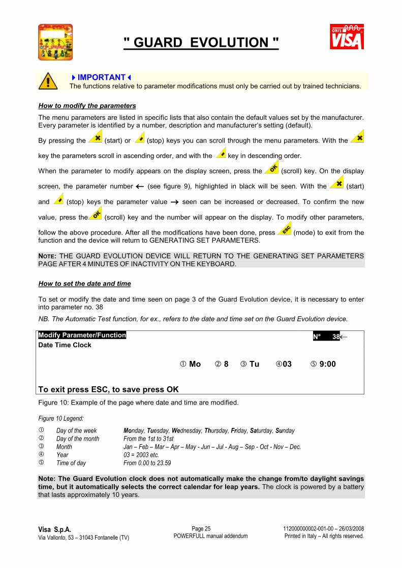
Modify Parameter/Function N� 38Date Time Clock
Mo 8 Tu 03 9:00
To exit press ESC, to save press OK Figure 10: Example of the page where date and time are modified.
Figure 10 Legend: Day of the week Monday, Tuesday, Wednesday, Thursday, Friday, Saturday, Sunday Day of the month From the 1st to 31st Month Jan – Feb – Mar – Apr – May - Jun – Jul - Aug – Sep - Oct - Nov – Dec. Year 03 = 2003 etc. Time of day From 0.00 to 23.59
Note: The Guard Evolution clock does not automatically make the change from/to daylight savings time, but it automatically selects the correct calendar for leap years. The clock is powered by a battery that lasts approximately 10 years.
" GUARD EVOLUTION "
Visa S.p.A.Via Vallonto, 53 – 31043 Fontanelle (TV) POWERFULL manual addendum
112000000002-001-00 – 26/03/2008Printed in Italy – All rights reserved.
Page 26
Enter into programming with the password, select parameter 38 and press the (scroll) key. The
parameter is highlighted in black (ex. Figure 10). With the (stop) key move the cursor to the value that
needs to be modified (day, week, day of the month, time) and then with the (start) key set the value.
For example, to set the weekday (as in Figure 10), press the key to move the cursor to weekday
desired and then to select the weekday required (in this case Mo = Monday). Proceed by pressing
the key to move the cursor on the date and set it with the (start) key, in this case the 8th. To
confirm the modifications/settings, press (scroll) and the parameter number is seen on the display. To modify other parameters, follow the above procedure. After all the modifications have been done, press
(mode) to exit from the function and the device will return to GENERATING SET PARAMETERS.
Setting the date and time for an automatic test (with or without load)
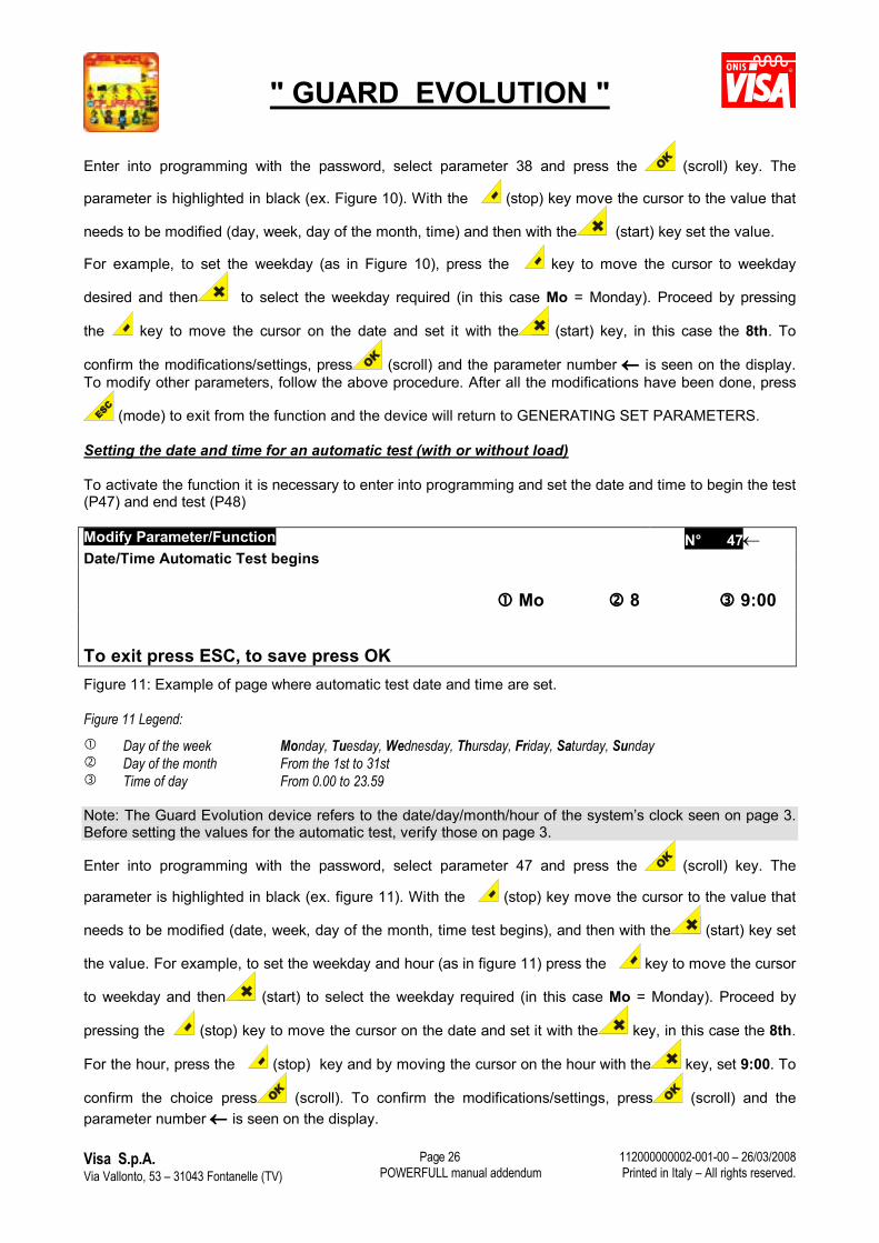
To activate the function it is necessary to enter into programming and set the date and time to begin the test (P47) and end test (P48)
Modify Parameter/Function N� 47Date/Time Automatic Test begins
Mo 8 9:00
To exit press ESC, to save press OK Figure 11: Example of page where automatic test date and time are set.
Figure 11 Legend: Day of the week Monday, Tuesday, Wednesday, Thursday, Friday, Saturday, Sunday Day of the month From the 1st to 31st Time of day From 0.00 to 23.59
Note: The Guard Evolution device refers to the date/day/month/hour of the system’s clock seen on page 3. Before setting the values for the automatic test, verify those on page 3.
Enter into programming with the password, select parameter 47 and press the (scroll) key. The
parameter is highlighted in black (ex. figure 11). With the (stop) key move the cursor to the value that
needs to be modified (date, week, day of the month, time test begins), and then with the (start) key set
the value. For example, to set the weekday and hour (as in figure 11) press the key to move the cursor
to weekday and then (start) to select the weekday required (in this case Mo = Monday). Proceed by
pressing the (stop) key to move the cursor on the date and set it with the key, in this case the 8th.
For the hour, press the (stop) key and by moving the cursor on the hour with the key, set 9:00. To
confirm the choice press (scroll). To confirm the modifications/settings, press (scroll) and the parameter number is seen on the display.
" GUARD EVOLUTION "
Visa S.p.A.Via Vallonto, 53 – 31043 Fontanelle (TV) POWERFULL manual addendum
112000000002-001-00 – 26/03/2008Printed in Italy – All rights reserved.
Page 27
To complete the test setting, select parameter 48. Press the (scroll) key and the parameter is highlighted in black (ex. figure 11). Set (following the above instructions) the day, week, date and hour when to end the test ex. Mo =
Monday 8 time 9:10. To confirm the modifications/settings, press (scroll) and the parameter number is seen on the display.
IMPORTANTIt is imperative that the date/time of the test be set correctly (parameters 47 and 48). An error in setting the times could initiate a test of excessive lengths (ex. 24 hours).
Setting the automatic test cycle
After setting parameters 47 and 48 to activate the Automatic Test function, set parameter 45 to indicate the cycle needed (daily, weekly or monthly).
Operating logic:After setting parameters 47 and 48 based on the cycle of parameter 45, the Automatic Test will be done as follows, referring to the values indicated in the example.
Begin Test (047) Mo 8 9:00End Test (048) Mo 8 9:10
Mode selectedDisabled: The automatic test is not executed; it is disabled (manufacturer’s default)Daily: The automatic test is executed daily, the test begins at 9:00 and ends at 9:10Weekly: The automatic test is executed every Monday, the test begins at 9:00 and ends at 9:10Monthly: The automatic test is executed the 8th of every month, the test begins at 9:00 and ends at
9:10
The device can only execute a single cycle of the Automatic Test (ie. once a day, once a week or once a month).
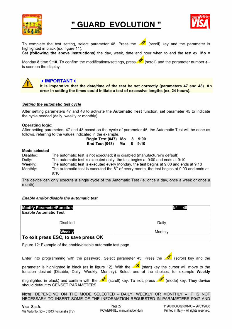
Enable and/or disable the automatic test
Modify Parameter/Function N� 45Enable Automatic Test
Disabled Daily
Weekly MonthlyTo exit press ESC, to save press OK Figure 12: Example of the enable/disable automatic test page.
Enter into programming with the password. Select parameter 45. Press the (scroll) key and the
parameter is highlighted in black (as in figure 12). With the (start) key the cursor will move to the function desired (Disable, Daily, Weekly, Monthly). Select one of the choices, for example Weekly
(highlighted in black) and confirm with the (scroll) key. To exit, press (mode) key. They device should default to GENSET PARAMETERS.
NOTE: DEPENDING ON THE MODE SELECTED - DAILY, WEEKLY OR MONTHLY – IT IS NOTNECESSARY TO INSERT SOME OF THE INFORMATION REQUESTED IN PARAMETERS P047 AND
" GUARD EVOLUTION "
Visa S.p.A.Via Vallonto, 53 – 31043 Fontanelle (TV) POWERFULL manual addendum
112000000002-001-00 – 26/03/2008Printed in Italy – All rights reserved.
Page 28
P048 AS IT WOULD BE REDUNDANT. WHEN DAILY IS SELECTED, IT IS NOT NECESSARY TO INSERTTHE DAY OR DATE. WHEN WEEKLY IS SELECTED, IT IS NOT NECESSARY TO INSERT THE DATE.AND WHEN MONTHLY IS SELECTED IT IS NOT NECESSARY TO INSERT THE DAY
NOTE: THE GUARD EVOLUTION DEVICE ALWAYS DEFAULTS TO GENSET PARAMETERS AFTER 4MINUTES OF INACTIVITY ON THE KEYBOARD.
SPECIAL FUNCTION DESCRIPTIONS
In this chapter the functions relative to parameter modifications and enabling function modes are described.Some of these functions are supplied as optional:
1 ACTIVE STOP function Standard2 Crank engine speed function Standard3 Countdown function (programming maintenance intervals) Standard4 Fuel pump command for automatic fuel tank refilling Optional5 PC connection Optional
1) ACTIVE STOP function (Service)
This function allows the possibility to feed the control system and engine stop for 52 minutes. This is indispensable for programming the control system of engines with incorporated electronic regulators or to bleed the fuel line where there are safety electro-valves powered by the generating set.
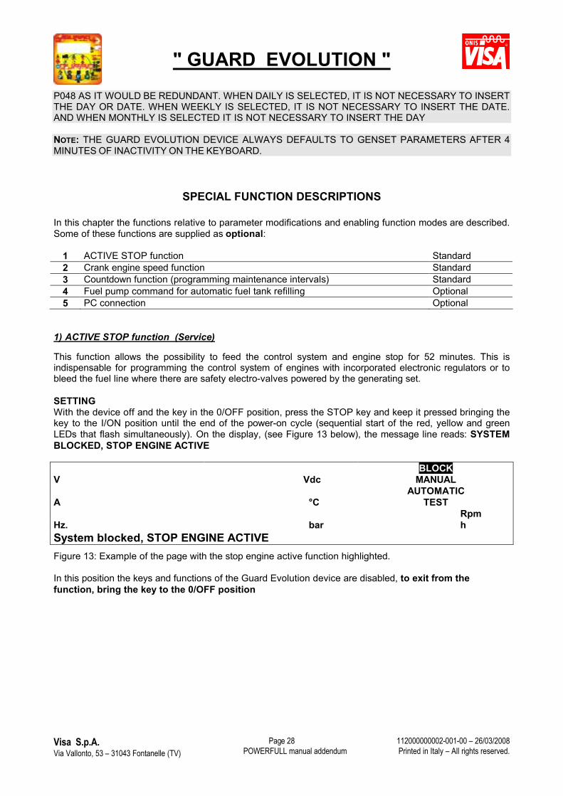
SETTINGWith the device off and the key in the 0/OFF position, press the STOP key and keep it pressed bringing the key to the I/ON position until the end of the power-on cycle (sequential start of the red, yellow and green LEDs that flash simultaneously). On the display, (see Figure 13 below), the message line reads: SYSTEM BLOCKED, STOP ENGINE ACTIVE
BLOCKV Vdc MANUAL
AUTOMATICA �C TEST
Rpm Hz. bar hSystem blocked, STOP ENGINE ACTIVEFigure 13: Example of the page with the stop engine active function highlighted.
In this position the keys and functions of the Guard Evolution device are disabled, to exit from the function, bring the key to the 0/OFF position
" GUARD EVOLUTION "
Visa S.p.A.Via Vallonto, 53 – 31043 Fontanelle (TV) POWERFULL manual addendum
112000000002-001-00 – 26/03/2008Printed in Italy – All rights reserved.
Page 29
2) CRANK ENGINE SPEED FUNCTION (Service /Assistance)
This function allows the diesel engine to turn over using the starting motor at crank engine speed without powering the stop engine device or the regulation system, therefore without starting the engine. This function is useful, especially with big engines, during an oil change to completely refill the cartridges and oil circuit before effectively starting the engine.
SETTINGSelect the MANUAL mode, press and keep pressed the STOP key; when the START key is pressed the engine will begin to turn over at crank speed until one of the 2 keys is released. After this operation, it is necessary to only press the START key when starting the generating set.
IMPORTANTThe starting motor must not work for more than 20 seconds continuously. IF THE OIL PRESSURE VALUE INCREASES, THIS INDICATES THAT THE CIRCUIT IS FILLING UP.
3) COUNTDOWN (REVERSE COUNTDOWN FOR MAINTENANCE)
As previously described, if the countdown function is enabled, it will indicate the number of hours that remain until the next programmed maintenance period. The remaining hours are indicated by the minus sign (-). If the deadline is surpassed, the hours are indicated as a positive number.Ex. –180 = 180 hours remain until programmed maintenance is requiredEx. 10 = programmed maintenance surpassed by 10 hoursN.B. The device shows the message “ENGINE MAINTENANCE REQUIRED” on the display screen when the countdown has expired.
4) SETTING AND MODIFYING THE VALUES
To access the COUNTDOWN menu, press the and (mode and stop) keys simultaneously. The page assigned to selecting intervals will appear on the display.
SET FUNCTION MODE N�2Programmed Maintenance
Disabled 50 hours 100 hours 150 hours200 hours 250 hours 300 hours 350 hours400 hours 450 hours 500 hours
Press ESC to Exit, Ok to saveFigure 14: Example of a countdown setting. In this example the 400 hour interval has been selected.
To select the interval, press the (start) key until the required value is shown highlighted in black. To
confirm the selection press the (scroll) key and the device will return to page 1. The selected interval value is always shown on page 2.
The function can be deactivated by selecting disabled.
" GUARD EVOLUTION "
Visa S.p.A.Via Vallonto, 53 – 31043 Fontanelle (TV) POWERFULL manual addendum
112000000002-001-00 – 26/03/2008Printed in Italy – All rights reserved.
Page 30
NOTE: AFTER EACH EXPIRED PROGRAMMED MAINTENANCE A NEW INTERVAL SHOULD BE SELECTED TO ZERO THE COUNTDOWN AND START AGAIN. If the new countdown period is not selected, the Guard Evolution device will continue to show the message Engine Maintenance required.
5) FUEL PUMP COMMAND FOR AUTOMATIC FUEL TANK REFILLING
If your Guard Evolution device is equipped with “Fuel pump command for automatic fuel tank refilling”, select the AUTOMATIC MODE AND SPECIAL FUNCTIONS page and the relevant information is viewed on the display screen.
R-S S-T T-R Hz Mo 08 Tu. 03 10 : 30Genset 400 400 400 50.0
Pump : MAN ON
MAN
To exit press ESC, to save press OK Figure 15: Example of the automatic refuelling page.
Figure 15 Legend: Indicates whether the automatic refuelling system is enabled or disabled on the device Refilling system function mode (can be MAN – AUT) Command status (can be ON or OFF )If your Guard Evolution device is equipped with the automatic refuelling function (an option that requires accessories mounted on the fuel tank – 4 level float, electro-pump, etc), it would also be able to provide for the automatic refuelling based on the generating set’s consumption. This function is optional and available with both the Manual and Automatic versions of the Guard Evolution device.
Operation
Through the selector lever on the electrical panel it is possible to select one of the three function modes seen on the display:
MAN: The fuel pump works continuously as long as the technician has the lever in the manual position. The lever has a return spring so when it is released the pump shuts off.However, the maximum level function remains active which generates the deactivation of the pump command, the warning signal, the yellow LED and remote alarm general contact.
“0” BLOCKED: The system is disabledAUT: The fuel pump operates automatically maintaining the generating set’s fuel tank full
based on the position of the 4 level float switch and the following functions:Minimum level = fuel reserve gives the Warning signal, lights up the yellow LED and activates the remote alarm general contactElectro-pump start = when the fuel dips below the set level, the system activates the pump until the level which stops the pump has been reached. Electro-pump stop = when the fuel has reached this level the pump shuts off and remains off until the fuel level dips below the level which starts the pump. Maximum level = if for some reason (a fault or the pump is manually forced) the pump continues to operate beyond the level for which the pump is set to stop, there is a Warning signal, yellow LED and activation of the remote alarm general contact.
" GUARD EVOLUTION "
Visa S.p.A.Via Vallonto, 53 – 31043 Fontanelle (TV) POWERFULL manual addendum
112000000002-001-00 – 26/03/2008Printed in Italy – All rights reserved.
Page 31
5 ) CONNNECTION TO A PERSONAL COMPUTER (optional)
Through accessories, supplied on request, it is possible to manage each function at a distance through a PC that uses Windows. All the details are described in the relative paragraph.
SEE ATTACHED 1
6 ) ALARM HISTORY (standard)
This function allows the last 15 Alarms to be seen that caused the unit to shut down. This function is particularly useful for understanding the probable causes and, above all, for supplying important information to the service technicians.
To access the alarm history, proceed as follows: Activate the device by bringing the key to the ON/I
position. Wait for the device to position itself on page 1, and in the BLOCK mode press the andkeys simultaneously (Mode and scroll) until the page where the password needs to be set appears and the cursor positions itself on the right hand side of the first character. Following the same procedure indicated on page 23 in the chapter Modify parameter functions, introduce thepassword 00000001. A page similar to that of GENSET PARAMETERS will appear on the display, on which the parameters and mode selected at the time the genset was blocked can be viewed besides the fault messages.
The progressive number (from 1-15) of the alarm viewed is highlighted in the top left hand side corner
(ref.). With the (start) and (stop) keys one can scroll up or down to see the pages with the memorised events/faults. 15 BLOCKV 400 13.8 Vdc MANUAL
AUTOMATICA 200 82 �C TEST
1500 Rpm Hz. 50 1.5 bar 6572 hLOW OIL PRESSURE
Figure 14: Example of the page with alarm 15 highlighted which refers to the engine oil pressure value that is outside the limit.
To exit from the Alarm History function press (mode). The device will return to the GENSET PARAMETERS page.
NOTE: CONSIDERING THE SMALL DIFFERENCE COMPARED TO THE NORMAL WORK PAGE IT IS ADVISED TO EXIT FROM THE FUNCTION ONCE DONE. HOWEVER, THE GUARD EVOLUTION WILL AUTOMATICALLY REVERT TO PAGE 1 AFTER 4MINUTES FROM THE LAST CHARACTER DIGITED.
" GUARD EVOLUTION "
Visa S.p.A.Via Vallonto, 53 – 31043 Fontanelle (TV) POWERFULL manual addendum
112000000002-001-00 – 26/03/2008Printed in Italy – All rights reserved.
Page 32
INCONVENIENCES AND SOLUTIONS
Inconveniences and possible solutions relative to the generating set and the control device installed in the electrical panel are discussed in this chapter.
WARNINGDo not carry out or undertake any maintenance operation, repair or modification unless you have the proper knowledge or have received the proper training.All of the operations must be carried out according to the safety norms.If there are still doubts after having read the manual and consulted the engine handbook, please do not hesitate to contact VISA or call the nearest authorised service centre.
ELECTRIC PANEL WITH “Guard Evolution” DEVICE
ELECTRIC PANEL MALFUNCTION PROBABLE CAUSES HOW TO INTERVENE
The device does not switch on Battery disconnected/deadInterrupted fuseFeeding circuit interrupted
Check system/installation
The device switches on but the display remains off
Incorrect display contrastDisplay cables disconnected or interruptedDisplay defect
Check system/installation
MT switch does not close Short circuit in the cablesDispersion in the cablesRelease bobbin fault
Check system/installation
INCONVENIENCES SIGNALLED BY THE GUARD EVOLUTION DEVICE
Most of the Warning messages are signals of events described below that have occurred but without permanent effects to the generating set (the set value’s limit was exceeded for a period of time less than that required to arrest the generating set). As we can see, some Warning messages are also found on the list of Alarm messages (faults), therefore it is important to check the possible cause preventing possible shutdowns.
NOTE: There can be messages that are not present on the list due to special requests. Some Warning messages can be set as Alarm (fault) messages and vice versa.
IMPORTANTDo not touch the electrical components mounted on the circuit of the GUARD EVOLUTION card with bare hands. It is possible that the above components can be damaged due to possibleelectrostatic loads.
" GUARD EVOLUTION "
Visa S.p.A.Via Vallonto, 53 – 31043 Fontanelle (TV) POWERFULL manual addendum
112000000002-001-00 – 26/03/2008Printed in Italy – All rights reserved.
Page 33
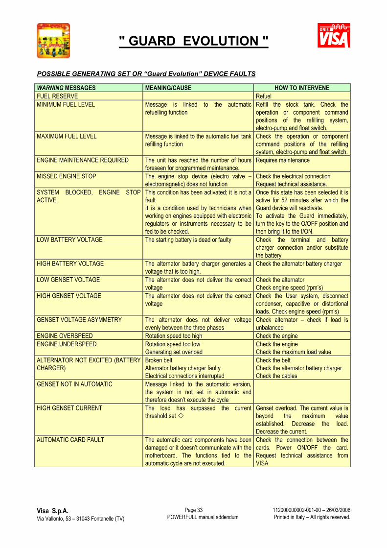
POSSIBLE GENERATING SET OR “Guard Evolution” DEVICE FAULTS
WARNING MESSAGES MEANING/CAUSE HOW TO INTERVENEFUEL RESERVE RefuelMINIMUM FUEL LEVEL Message is linked to the automatic
refuelling functionRefill the stock tank. Check the operation or component command positions of the refilling system, electro-pump and float switch.
MAXIMUM FUEL LEVEL Message is linked to the automatic fuel tank refilling function
Check the operation or component command positions of the refilling system, electro-pump and float switch.
ENGINE MAINTENANCE REQUIRED The unit has reached the number of hours foreseen for programmed maintenance.
Requires maintenance
MISSED ENGINE STOP The engine stop device (electro valve –electromagnetic) does not function
Check the electrical connection Request technical assistance.
SYSTEM BLOCKED, ENGINE STOP ACTIVE
This condition has been activated; it is not a faultIt is a condition used by technicians when working on engines equipped with electronic regulators or instruments necessary to be fed to be checked.
Once this state has been selected it is active for 52 minutes after which the Guard device will reactivate.To activate the Guard immediately, turn the key to the O/OFF position and then bring it to the I/ON.
LOW BATTERY VOLTAGE The starting battery is dead or faulty Check the terminal and battery charger connection and/or substitute the battery
HIGH BATTERY VOLTAGE The alternator battery charger generates a voltage that is too high.
Check the alternator battery charger
LOW GENSET VOLTAGE The alternator does not deliver the correct voltage
Check the alternatorCheck engine speed (rpm’s)
HIGH GENSET VOLTAGE The alternator does not deliver the correct voltage
Check the User system, disconnectcondenser, capacitive or distortional loads. Check engine speed (rpm’s)
GENSET VOLTAGE ASYMMETRY The alternator does not deliver voltage evenly between the three phases
Check alternator – check if load is unbalanced
ENGINE OVERSPEED Rotation speed too high Check the engineENGINE UNDERSPEED Rotation speed too low
Generating set overloadCheck the engine Check the maximum load value
ALTERNATOR NOT EXCITED (BATTERY CHARGER)
Broken beltAlternator battery charger faultyElectrical connections interrupted
Check the beltCheck the alternator battery chargerCheck the cables
GENSET NOT IN AUTOMATIC Message linked to the automatic version, the system in not set in automatic and therefore doesn’t execute the cycle
HIGH GENSET CURRENT The load has surpassed the current threshold set
Genset overload. The current value is beyond the maximum value established. Decrease the load. Decrease the current.
AUTOMATIC CARD FAULT The automatic card components have been damaged or it doesn’t communicate with the motherboard. The functions tied to the automatic cycle are not executed.
Check the connection between the cards. Power ON/OFF the card. Request technical assistance from VISA
" GUARD EVOLUTION "
Visa S.p.A.Via Vallonto, 53 – 31043 Fontanelle (TV) POWERFULL manual addendum
112000000002-001-00 – 26/03/2008Printed in Italy – All rights reserved.
Page 34
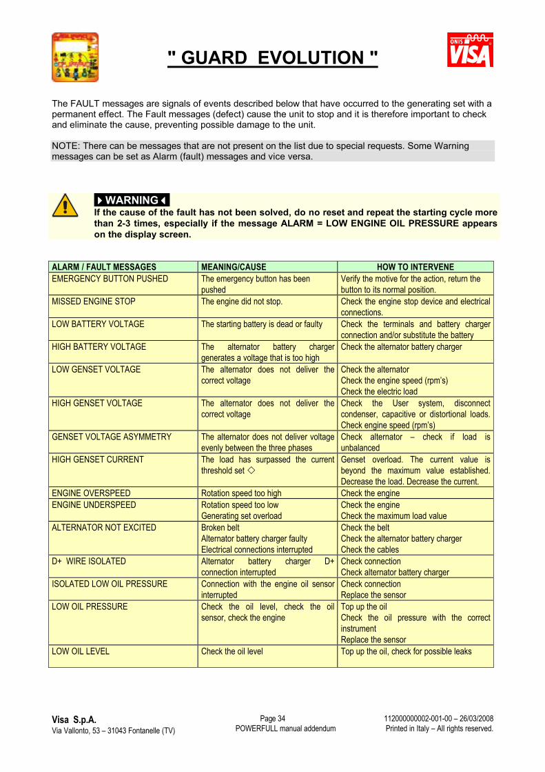
The FAULT messages are signals of events described below that have occurred to the generating set with a permanent effect. The Fault messages (defect) cause the unit to stop and it is therefore important to check and eliminate the cause, preventing possible damage to the unit.
NOTE: There can be messages that are not present on the list due to special requests. Some Warning messages can be set as Alarm (fault) messages and vice versa.
WARNINGIf the cause of the fault has not been solved, do no reset and repeat the starting cycle more than 2-3 times, especially if the message ALARM = LOW ENGINE OIL PRESSURE appears on the display screen.
ALARM / FAULT MESSAGES MEANING/CAUSE HOW TO INTERVENEEMERGENCY BUTTON PUSHED The emergency button has been
pushedVerify the motive for the action, return the button to its normal position.
MISSED ENGINE STOP The engine did not stop. Check the engine stop device and electrical connections.
LOW BATTERY VOLTAGE The starting battery is dead or faulty Check the terminals and battery charger connection and/or substitute the battery
HIGH BATTERY VOLTAGE The alternator battery charger generates a voltage that is too high
Check the alternator battery charger
LOW GENSET VOLTAGE The alternator does not deliver the correct voltage
Check the alternatorCheck the engine speed (rpm’s)Check the electric load
HIGH GENSET VOLTAGE The alternator does not deliver the correct voltage
Check the User system, disconnectcondenser, capacitive or distortional loads.Check engine speed (rpm’s)
GENSET VOLTAGE ASYMMETRY The alternator does not deliver voltage evenly between the three phases
Check alternator – check if load is unbalanced
HIGH GENSET CURRENT The load has surpassed the current threshold set
Genset overload. The current value is beyond the maximum value established. Decrease the load. Decrease the current.
ENGINE OVERSPEED Rotation speed too high Check the engineENGINE UNDERSPEED Rotation speed too low
Generating set overloadCheck the engine Check the maximum load value
ALTERNATOR NOT EXCITED Broken beltAlternator battery charger faultyElectrical connections interrupted
Check the beltCheck the alternator battery chargerCheck the cables
D+ WIRE ISOLATED Alternator battery charger D+ connection interrupted
Check connectionCheck alternator battery charger
ISOLATED LOW OIL PRESSURE Connection with the engine oil sensor interrupted
Check connectionReplace the sensor
LOW OIL PRESSURE Check the oil level, check the oil sensor, check the engine
Top up the oilCheck the oil pressure with the correct instrumentReplace the sensor
LOW OIL LEVEL Check the oil level Top up the oil, check for possible leaks
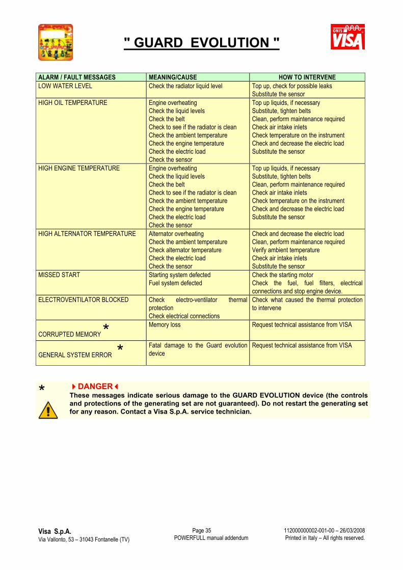
" GUARD EVOLUTION "
Visa S.p.A.Via Vallonto, 53 – 31043 Fontanelle (TV) POWERFULL manual addendum
112000000002-001-00 – 26/03/2008Printed in Italy – All rights reserved.
Page 35
ALARM / FAULT MESSAGES MEANING/CAUSE HOW TO INTERVENELOW WATER LEVEL Check the radiator liquid level Top up, check for possible leaks
Substitute the sensorHIGH OIL TEMPERATURE Engine overheating
Check the liquid levelsCheck the beltCheck to see if the radiator is cleanCheck the ambient temperatureCheck the engine temperatureCheck the electric loadCheck the sensor
Top up liquids, if necessarySubstitute, tighten beltsClean, perform maintenance requiredCheck air intake inletsCheck temperature on the instrumentCheck and decrease the electric loadSubstitute the sensor
HIGH ENGINE TEMPERATURE Engine overheatingCheck the liquid levelsCheck the beltCheck to see if the radiator is cleanCheck the ambient temperatureCheck the engine temperatureCheck the electric loadCheck the sensor
Top up liquids, if necessarySubstitute, tighten beltsClean, perform maintenance requiredCheck air intake inletsCheck temperature on the instrumentCheck and decrease the electric loadSubstitute the sensor
HIGH ALTERNATOR TEMPERATURE Alternator overheating Check the ambient temperatureCheck alternator temperature Check the electric loadCheck the sensor
Check and decrease the electric loadClean, perform maintenance requiredVerify ambient temperatureCheck air intake inletsSubstitute the sensor
MISSED START Starting system defectedFuel system defected
Check the starting motorCheck the fuel, fuel filters, electrical connections and stop engine device.
ELECTROVENTILATOR BLOCKED Check electro-ventilator thermal protectionCheck electrical connections
Check what caused the thermal protection to intervene
CORRUPTED MEMORY * Memory loss Request technical assistance from VISA
GENERAL SYSTEM ERROR * Fatal damage to the Guard evolutiondevice
Request technical assistance from VISA
* DANGERThese messages indicate serious damage to the GUARD EVOLUTION device (the controls and protections of the generating set are not guaranteed). Do not restart the generating set for any reason. Contact a Visa S.p.A. service technician.
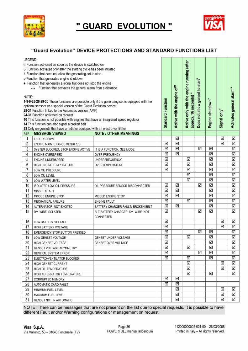
" GUARD EVOLUTION "
Visa S.p.A.Via Vallonto, 53 – 31043 Fontanelle (TV) POWERFULL manual addendum
112000000002-001-00 – 26/03/2008Printed in Italy – All rights reserved.
Page 36
“Guard Evolution” DEVICE PROTECTIONS AND STANDARD FUNCTIONS LIST
LEGEND: Function activated as soon as the device is switched on Function activated only after the starting cycle has been initiated Function that does not allow the generating set to start Function that generates engine shutdown Function that generates a signal but does not stop the engine
Function that activates the general alarm from a distance
NOTE:1-8-9-25-26-29-30 These functions are possible only if the generating set is equipped with the optional sensors or a special version of the Guard Evolution device28-31 Function linked to the Automatic version (AMF)24-31 Function activated on request10 This function is not possible with engines that have an integrated speed regulator14 This function can also signal a broken belt 23 Only on gensets that have a radiator equipped with an electro-ventilator St
anda
rd F
unct
ion
Activ
e with
the e
ngin
e off
Activ
e onl
y with
the e
ngin
e run
ning
(afte
r ap
prox
. 16 s
econ
ds)
Does
not
allo
w ge
nset
to st
art
Engi
ne sh
utdo
wn
Sign
al on
ly
Activ
ates
gen
eral
alarm
REF MESSAGE VIEWED NOTE / OTHER MEANINGS1 FUEL RESERVE 2 ENGINE MAINTENANCE REQUIRED 3 SYSTEM BLOCKED, STOP ENGINE ACTIVE IT IS A FUNCTION, SEE MODE 4 ENGINE OVERSPEED OVER FREQUENCY 5 ENGINE UNDERSPEED UNDERFREQUENCY 6 HIGH ENGINE TEMPERATURE OVERTEMPERATURE 7 LOW OIL PRESSURE 8 LOW OIL LEVEL 9 LOW WATER LEVEL 10 ISOLATED LOW OIL PRESSURE OIL PRESSURE SENSOR DISCONNECTED 11 MISSED START 12 MISSED ENGINE STOP MISSED ENGINE STOP 13 MECHANICAL FAILURE ENGINE FAULT 14 ALTERNATOR NOT EXCITED BATTERY CHARGER FAULT/ BROKEN BELT 15 D+ WIRE ISOLATED ALT BATTERY CHARGER D+ WIRE NOT
CONNECTED
16 LOW BATTERY VOLTAGE 17 HIGH BATTERY VOLTAGE 18 EMERGENCY STOP BUTTON PRESSED 19 LOW GENSET VOLTAGE GENSET UNDER VOLTAGE 20 HIGH GENSET VOLTAGE GENSET OVER VOLTAGE 21 GENSET VOLTAGE ASYMMETRY 22 GENERAL SYSTEM ERROR 23 ELECTRO-VENTILATOR BLOCKED 24 HIGH GENSET CURRENT 25 HIGH OIL TEMPERATURE 26 HIGH ALTERNATOR TEMPERATURE 27 CORRUPTED MEMORY 28 AUTOMATIC CARD FAULT 29 MINIMUM FUEL LEVEL 30 MAXIMUM FUEL LEVEL 31 GENSET NOT IN AUTOMATIC
NOTE: There can be messages that are not present on the list due to special requests. It is possible to have different Fault and/or Warning configurations or management on request.
" GUARD EVOLUTION "
Visa S.p.A.Via Vallonto, 53 – 31043 Fontanelle (TV) POWERFULL manual addendum
112000000002-001-00 – 26/03/2008Printed in Italy – All rights reserved.
Page 37
T A B L E O F C O N T E N T S GENERAL DESCRIPTION.......................................................................................................................... 1KEY FUNCTIONS ....................................................................................................................................... 2
START..................................................................................................................................................... 2STOP....................................................................................................................................................... 2MODE...................................................................................................................................................... 2SCROLL (change page) ........................................................................................................................... 3
MEANING OF THE LED’s AND ALARM..................................................................................................... 4DISPLAY SCREEN MESSAGES AND DATA.............................................................................................. 5
GENERATING SET INFORMATION (Page 0) ......................................................................................... 5GENERATING SET PARAMETERS (Page 1 main page)......................................................................... 5GENERATING SET ELECTRICAL PARAMETER DETAILS (Page 2) ...................................................... 6AUTOMATIC MODE AND SPECIAL FUNCTIONS (Page 3) .................................................................... 7
GENERAL OPERATION MODE OF THE VARIOUS VERSIONS................................................................ 8HOW TO RECOGNISE THE VERSION AT YOUR DISPOSAL.................................................................. 8“MANUAL” VERSION................................................................................................................................. 9
Selecting the MANUAL mode - Genset Start and Stop ............................................................................. 9Genset Start and Stop.............................................................................................................................. 9Genset Start............................................................................................................................................10Genset stop.............................................................................................................................................10
“AUTOMATIC” REMOTE COMMAND VERSION (AUTOSTART) (OPTIONAL)........................................10SELECTING THE AUTOMATIC MODE ..................................................................................................10MANUAL CHANGEOVER OPERATION .................................................................................................12
“AUTOMATIC” MAINS FAILURE VERSION (AMF) (OPTIONAL) .............................................................13FUNCTION MODE DESCRIPTIONS..........................................................................................................14
BLOCK....................................................................................................................................................14MANUAL.................................................................................................................................................14MANUAL CHANGEOVER OPERATION .................................................................................................15AUTOMATIC...........................................................................................................................................15 Mains status communication ............................................................................................................16 Load status communication..............................................................................................................17 Communication of the function/command being executed ................................................................17 Time set relative to the function/command being executed, with countdown.....................................17
AUTOMATIC CYCLE DESCRIPTION .....................................................................................................17TEST ......................................................................................................................................................18
Manual Test.........................................................................................................................................18Automatic Test (with and without load).................................................................................................19
SELECTING THE AUTOMATIC MODE .....................................................................................................20PARAMETERS LIST (THOSE MODIFIED THROUGH THE USER MENU) ...............................................22
PARAMETER DESCRIPTIONS ..............................................................................................................23MODIFY PARAMETERS (User menu) ....................................................................................................23
How to insert the password to access the parameters..........................................................................24How to modify the parameters .............................................................................................................25How to set the date and time ...............................................................................................................25Setting the date and time for an automatic test (with or without load) ...................................................26Setting the automatic test cycle............................................................................................................27Enable and/or disable the automatic test ..............................................................................................27
SPECIAL FUNCTION DESCRIPTIONS .....................................................................................................281) ACTIVE STOP function (Service).......................................................................................................282) CRANK ENGINE SPEED FUNCTION (Service /Assistance) ...............................................................293) COUNTDOWN (REVERSE COUNTDOWN FOR MAINTENANCE) ....................................................294) SETTING AND MODIFYING THE VALUES ........................................................................................295) FUEL PUMP COMMAND FOR AUTOMATIC FUEL TANK REFILLING ..............................................30
INCONVENIENCES AND SOLUTIONS .....................................................................................................32ELECTRIC PANEL WITH “Guard Evolution” DEVICE.............................................................................32INCONVENIENCES SIGNALLED BY THE GUARD EVOLUTION DEVICE.............................................32POSSIBLE GENERATING SET OR “Guard Evolution” DEVICE FAULTS...............................................33
“Guard Evolution” DEVICE PROTECTIONS AND STANDARD FUNCTIONS LIST ................................36