g. tipton laque center for corrosion technology, inc. · d. g. tipton laque center for corrosion...
TRANSCRIPT

0337-1 74677
D. G. Tipton LaQue Center for Corrosion Technology, Inc.
Prepared for
for
https://ntrs.nasa.gov/search.jsp?R=19840019260 2018-07-27T14:19:18+00:00Z

DISCLAIMER
This report was prepared as an account of work sponsored by an agency of the United States Government. Neither the United States Government nor any agency thereof, nor any of their employees, makes any warranty, express or implied, or assumes any legal liability or responsibility for the accuracy, completeness, or usefulness of any information, apparatus, product, or process disclosed, or represents that its use would not infringe privately owned rights. Reference herein to any specific commercial product, process, or service by trade name, trademark, manufacturer, or otherwise, does not necessarily constitute or imply its endorsement, recommendation, or favoring by the United States Government or any agency thereof. The views and opinions of authors expressed herein do not necessarily state or reflect those of the United States Government or any agency thereof.
Printed in the United States of America Available from
National Technical Information Service US. Department of Commerce 5285 Port Royal Road Springfield, VA 22161
Printed copy: A 0 2 Microfiche copy: A01
NTlS price codes1
1Codes are used for pricing all publications. The code is determined by the number of pages in the publication. Information pertaining to the pricing codes can be found in the current issues of the following publications, which are generally available in most libraries: Energy Research Absiracts (ERA); Government Reports Announcements and Index (GRA and I); Scientific and Technical Abstract Repqrts (STAR); and publication, NTIS-PR-360 available from NTlS at the above address.

DOEINASN0337-1 NASA CR-174677
Corrosion Fatigue of High Strength Fastener Materials in Seawater
D. G. Tipton LaQue Center for Corrosion Technology, Inc. Wrightsville Beach, North Carolina 28480
December 1983
Prepared for National Aeronautics and Space Administration Lewis Research Center Cleveland, Ohio 441 35 Under Contract DEN 3-337
for U.S. DEPARTMENT OF ENERGY Conservation and Renewable Energy Wind Energy Technology Division Washington, D.C. 20545 Under interagency Agreement DE-AI01 -76ET20320

SUMMARY
Environmental effects can significantly reduce t h e fat igue l ife of metals. As such, corrosion fat igue is a major concern in the engineering application of high s t rength mater ia ls in marine environments. One cr i t ical use of high s t rength materials in marine environments is for fasteners which may be subjected to cycl ic stresses superimposed over relatively high s t a t i c axial stresses. This results in ra ther high ratios of minimum to maximum stress. High s t ress ratios are generally considered detr imental to corrosion fa t igue s t rength but t h e d a t a base is not extensive for engineering materials.
The failure of a n AISI 41L40 high s t rength s tee l blade-to-hub a t tachment bolt at t h e MOD-OA 200 KW wind turbine generator in Oahu, Hawaii prompted t h e current test program. The cause of this failure was determined to be corrosion fat igue due to t h e combined act ion of normal fatigue loads at high s t ress ratios and t h e corrosive marine atmosphere.
Tests were undertaken to confirm t h e dramat ic reduction of fat igue strength of AISI 41L40 in marine environments and to obtain similar corrosion fat igue d a t a for candidate replacement materials. AISI 41L40, AISI 4140, PH 13-8Mo stainless steel, alloy 718 and alloy MP-35N were tested in axial fa t igue at a frequency of 20 Hz in dry a i r and natural seawater . The fat igue da ta were f i t t ed by regression equations to allow determination of fa t igue s t rength for a given number of cycles to failure.
Results of t h e tests demonstrated a 77% reduction in fa t igue s t rength (versus fa t igue in a i r ) fo r 41L40, a 72% reduction for 4140, a 51% reduction for PH 13-8 Mo, a 15% reduction for MP-35N, and a 4% reduction for alloy 718. The 4140 and 41L40 failed at stresses well below t h e normal operat ing s t resses in a relatively few number of cycles. Pi t t ing corrosion was observed to accompany corrosion fat igue failure of PH 13-8 Mo. Relatively l i t t l e environmental effect was observed for alloy 718 and MP-35N.
INTRODUCTION
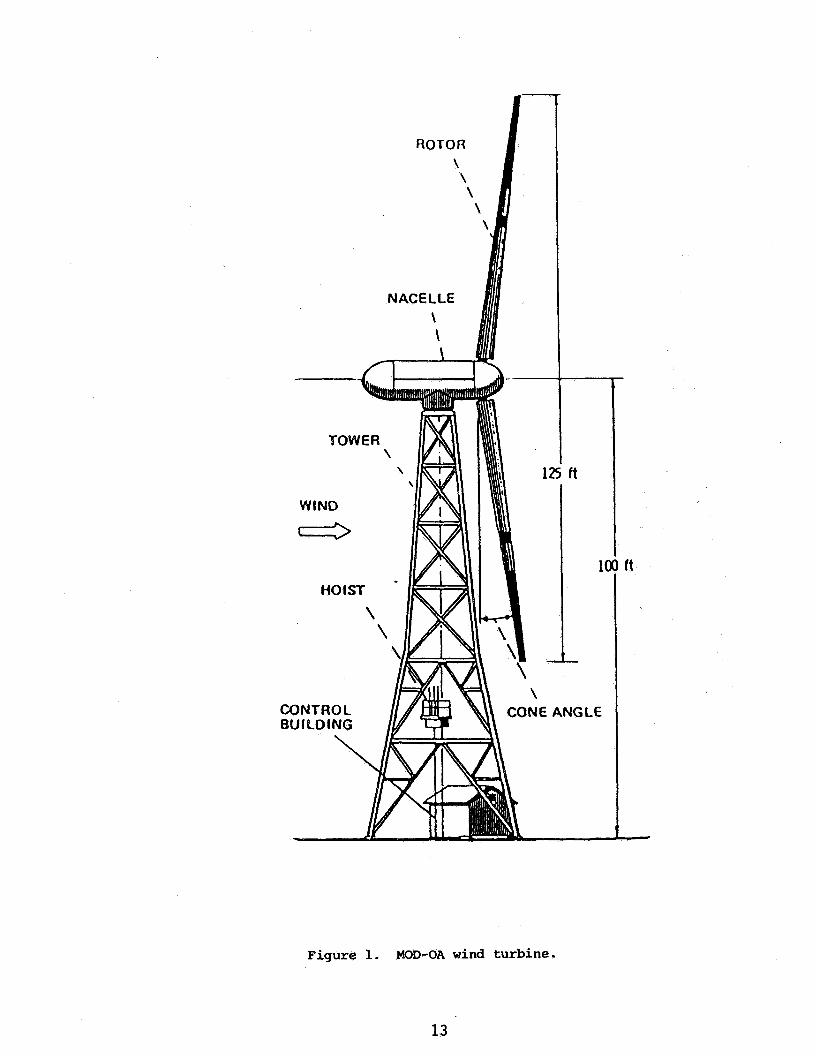
The US. Federal Wind Energy Program was established to enable research and development on various applications of wind energy systems. The program was originally administered by t h e National Science Foundation, and is current ly directed and funded by t h e U.S. Department of Energy. One phase of t h e program involves t h e design, fabrication and experimental operation of large horizontal axis wind turbine generators. This par t of t h e program is managed by the Lewis Research Cen te r of the National Aeronautics and Space Administration. The f i rs t wind turbine generators to be placed into uti l i ty operation under this program were four 200 kW horizontal axis machines designated MOD-OA. Figure 1 shows a schemat ic drawing of t h e s t ructure .
The purpose of t h e MOD-OA experimental installation was to obtain ear ly operation and performance data while gaining experience in the operation of a large wind turbine in various utility environments. These wind turbines were built and installed at Clayton,

New Mexico in 1978; at Culebra, Puerto Rico in 1979; a t Block island, Rhode Island in 1979; and at Kahuku Point, Oahu, Hawaii in 1980 (Ref. 1).
Around November 11, 1981, a failure occurred on the MOD-OA wind turbine generator at Kahuku Point, Oahu, Hawaii. The failure was one of the 24 AISI 41L40 high s t rength s tee l blade-to-hub a t t achmen t studs. Figure 2 shows t h e location and design details of t h e studs. The cause of t h e cracking was determined to be corrosion fat igue due to the combined action of fat igue loads and t h e corrosive marine atmosphere (Ref. 2).
A study was undertaken at t h e LaQue Center for Corrosion Technology, Inc. (LCCT) for t w o reasons. The f i r s t was to confirm corrosion fat igue as a plausible cause of fai lure of 41L40 fas teners in a marine environment. The second goal was to obtain corrosion fa t igue data for three candidate replacement alloys.
EXPERIMENTAL
AIS1 41L40 high s t rength s tee l was evaluated to charac te r ize the corrosion fat igue s t rength of t h e mater ia l of construction of t h e failed stud. AISI 4140 was included for comparison. 41L40 is essentially a compositional variation of 4140 with Pb added for improved machinability.
Three candidate replacement alloys were included in t h e study on the basis of their ant ic ipated higher corrosion fa t igue strength. These alloys included PH 13-8 Mo stainless steel, alloy 718, and Mutiphase MP-35NTM. All mater ia ls for test specimens were obtained as commerically produced y2 inch d iameter rod s tock products. Table I gives t h e sources, hea t t r ea tmen t s and relevant specifications. Table I1 gives the compositions of t h e f ive materials. All compositions and heat t r ea tmen t s represent typical commercial production and primary manufacturers recommendations for high fa t igue strength.
Mechanical properties were determined according to ASTM Standard Method E8 o n "Tension Testing of Metall ic Materials," f rom specimens selected from t h e s tock of fa t igue specimens. The mechanical properties a r e given in Table 111.
specimen Production
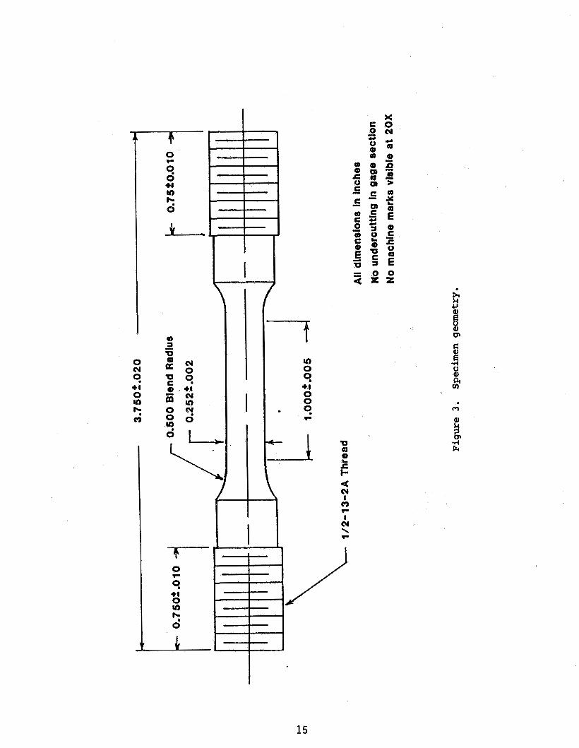
All specimens were machined to threaded end, reduced gauge sect ion geometry as shown in Figure 3. Final h e a t t r ea tmen t s were performed a f t e r machining to avoid any residual stress e f f e c t s f rom the machining operation. The specimen gauge section was ground to 320 g r i t just prior to testing. The grinding paper was ro ta ted on a YU inch sha f t perpendicular to t h e specimen axis while t h e specimen was rotated. As a result, a l l grinding marks on t h e specimen gauge sect ion were in a longitudinal direction and not in t h e circumferent ia l direction, where s t ress concentrat ion could result during axial fa t igue loading producing ear ly fa i lure and increased data sca t te r .
Apparatus and Test Parameters
All fa t igue tests were performed in accordance with ASTM Recommended Prac t ice E466 on "Constant Amplitude Axial Fat igue Tests of Metall ic Materials," using a n MTSTM closed-loop servo-hydraulic fa t igue testing system, as shown schematical ly in Figure 4.
2

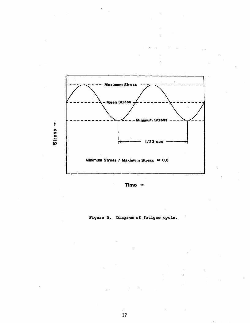
The machine was operated in load control. The fatigue parameters were taken from the NASA stress analyses of the blade studs on the MOD-OA wind turbine operating under extreme conditions at high wind loads and rotating speeds. The fatigue wave form was a 20 Hz sine wave. A l l tests were conducted at a constant load ratio of minimum stress divided by maximum stress, R = 0.6. Figure 5 shows diagrammatically the stress cycle used.
All tests were conducted unti l failure or 10 million cycles occurred.
Environments
Two environments were utilized, air and natural seawater. A i r was included as a comparative standard to determine the magnitude of the loss in fatigue strength due to the corrosive environment. Design fatigue data i s typically generated in air, but l i t t l e data i s available for stress ratios near 0.6 and/or in marine environments.
The field failure at Kahuku Point was in a marine atmospheric environment with high levels of airborne chlorides available and high dew point conditions. The studs are partially covered by the hub fairing, eliminating washing of deposited chlorides by rainfall. The field environment was conservatively approximated by a drip feed of natural seawater which was temperature controlled to 30OC and applied to the horizontally configured specimen. Due to dryout conditions, the gauge section of the specimen was exposed to saturated marine salts on the edges of the gauge section and a thin layer of seawater at the center. Rubber washers were installed on the ends of the specimen during test to avoid galvanic effects of seawater contact on the threaded alloy 625 grips.
RESULTS AND DISCUSSION
Table IV summarizes the fatigue data obtained. The data are plotted as mean stress versus log cycles to failure (S-N) curves in Figures 6-10. As indicated, several specimens failed outside the test section i n the machined threads - owing to the high stresses involved (with respect to the yield stress) and the notch acuity in the threads. Data from the specimens that failed i n the threads was not included in the analysis.
The data were analyzed by non-linear regression analysis in which the data were f i t ted to equations of the form:
log (S-Se) = m* log (N) + b
were S is mean stress in ksi, N is cycles to failure, Se is a constant akin to an endurance l imit, and m and b are regression constants. The resultant regression equations are given below along with the correlation coefficient, C (unity indicates perfect correlation):
4 1 L40: air log (S-172) = -1.473 log (N) + 8.310 C = 0.990
seawater log 6-40] = -3.297 log (N) + 22.216 C = 0.999
3

4 140: -
PH 13-8 Mo:
alloy 718:
M P-3 5N:
a i r log ( S - 150) = -2.1 I9 log (N) + 12.673 C = 0.902
seawater log (S-0) = -0.28 13 log (N) + 3.598 C = 0.942
a i r log (S-0) = -0.02163 log (N) + 2.288 C = 0.999
seawater log 6-67] = -1.7491 log (N) + 11.922 C = 0.999
a i r log (S-0) = -0.01564 log (N) + 2.242 C = 0.936
seawa te r log (S-130) = -1.862 log (N) + 11.182 C = 0.924
a i r log (S-0) = -0.03169 log (N) + 2.388 c = 0.998
seawater log (S-120) = -0.7226 log (N) + 5.668 C = 0.949
Figures 6-10 show t h e above regression equations plotted in addition to the raw data. Good correlation was obtained, as indicated by both t h e correlation coefficient and t h e graphical S-N curve plots. The corrosion fatigue s t rength was es t imated from t h e above equations by computing t h e mean s t ress for 10 million cycles life. These fat igue s t rength e s t ima tes are summarized in Table V for the f ive alloys in a i r and seawater.
41L40 shows t h e highest fa t igue strength in air, but t h e lowest in seawater. The performance of 4140 is very nearly equal to tha t of the 41L40. Both alloys lose over 70% of their air fa t igue s t r eng th in seawater. These results a r e consistent with o the r corrosion fatigue data reported for AIS1 4130 steel in which t h e corrosion fat igue s t rength at R=-1 was 68% less than t h e a i r fatigue strength (Ref. 3).
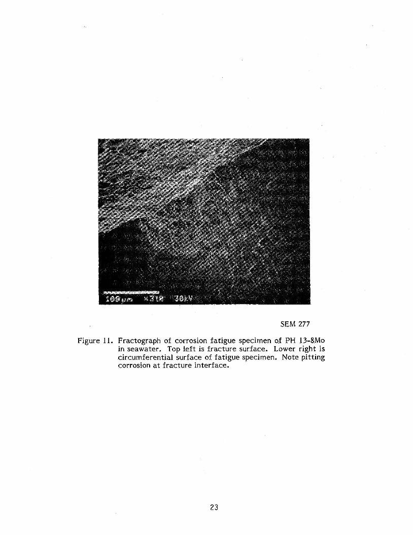
PH 13-8 Mo has t h e next highest fatigue strength in seawater, but i t still represents a g rea t e r than 50% reduction from t h e a i r fatigue strength. One cause for concern in t h e use of PH 13-8 Mo in cr i t ical corrosion fatigue application in seawater is i t s tendency toward pit t ing corrosion which c a n serve to concentrate stresses and provide ear ly initiation of fat igue failure. Indeed, one test specimen experienced pit t ing corrosion and probable init iation of t h e corrosion fat igue f rac ture from the pit as shown in t h e SEM micrograph in Figure 11.
Alloy MP-35N showed significantly higher corrosion fatigue s t rength - a lmost double t h a t of PH 13-8 Mo and t r iple t h a t of 41L40. The fat igue strength in seawa te r was only 15% less than t h e a i r fatigue strength. With i t s highly alloyed composition (9% Mo), MP- 35N is not considered susceptible to pitting corrrosion in seawater (Ref. 4). High resistance to crevice corrosion in seawater has also been reported (Ref. 5).
4

Alloy 718 had the highest corrosion fat igue s t rength of al l f ive alloys. The corrosion fat igue s t rength was only 4% less than the a i r fa t igue strength. Although some sensitivity to crevice corrosion has been reported, alloy 7 18 is not considered susceptible to pit t ing corrosion in typical seawater environments (Ref. 4, 6).
CONCLUSIONS
AISI 41L40 and AISI 4140 high s t rength s tee ls a r e extremely susceptible to corrosion fat igue failure in marine environments. Fat igue s t rength can suffer losses of over 70% as compared to dry air.
PH 13-8 Mo can offer improved (versus 41L40 o r 4140) corrosion fat igue perfor- mance in seawater but seawater c a n still reduce fat igue s t rength by over 50%. The observed susceptibility to pit t ing corrosion suggests ex t r eme caution for cr i t ical corrro- sion fat igue application in seawater .
Alloy 718 and Multiphase alloy MP-35N o f fe r very good resistance to corrosion fat igue in seawater . Seawater corrosion fat igue properties of alloy 718 a r e very nearly equal to those in air ,
When high s t rength alloys a r e required for cr i t ical fas tener applications in marine applications, including marine atmospheres, carefu i a t ten t ion must be paid to corrosion fatigue. All t h e advantage of high s t rength s t ee l can be lost by reductions of up to 70% and more in fa t igue s t rength by t h e marine environment.
As expected, high stress ratios fur ther reduce corrosion fat igue strength. Engineering fat igue design for service in corrosive environments should include fa t igue d a t a generated in t h e corrosive environment.
ACKNOWLEDGEMENT
This work was sponsored by t h e National Aeronautics and Space Administration, Lewis Research Center and funded by t h e United States Department of Energy under Con t rac t DEN 3-337. The NASA Projec t Manager was Richard K. Shaltens.
5
REFERENCES
1. Shaltens, R. K. and Birchenough, A. G., "Operational Results for the Experimental DOE/NASA MOD-OA Wind Turbine Project," DOE/NASA/20320-55, NASA TM-83517, 1983.
2. Faddoul, J., "Examination, Evaluation, and Repair of Laminated Wood Blades After Service on the MOD-OA Wind Turbine," DOE/NASA/20320-53, NASA TM-83483, 1983.
3. Fuchs, H. 0. and Stephens, R. I., Metal Fatigue in Engineering, Wiley-Interscience, New York, 1980, p. 303.
4. Fink, F. W. and Boyd, W. K., "The Corrosion of Metals in Marine Environments," Defense Metals Information Center, Battelle Memorial Institute, Columbus, Ohio, DMIC Report 245, May, 1970.
5. Stroup, J. P., Baurnan, A. H., and Simkovich, A., "Multiphase MP35N - An Alloy for Deep Sour Well Service," Materials Performance, Vol. 15, June, 1976, pp. 43-47.
Reinhart, F. M., "Corrosion of Materials in Hydrospace," US. Naval Civ i l Engineer- ing Laboratory, Port Hueneme, California, Report R-504, December, 1966.
6 .
6
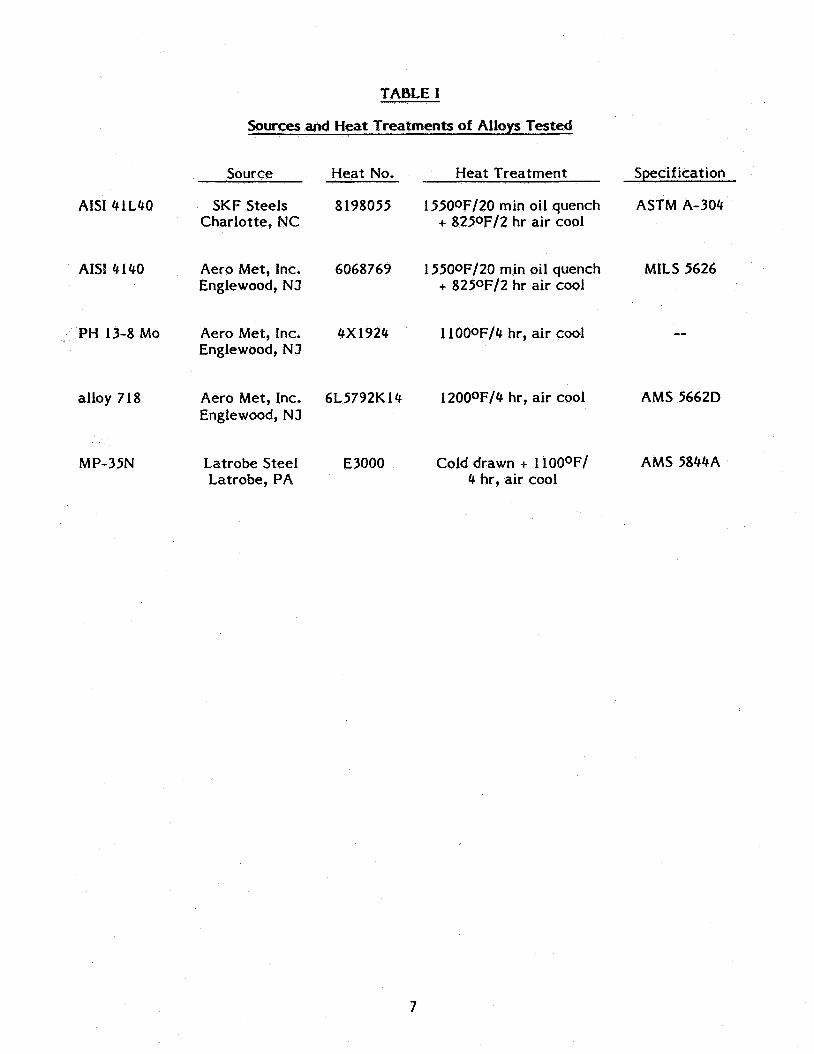
TABLE I
Sources and Heat Treatments of Alloys Tested
AISI 4lL40
AISI 4 140
PH 13-8 MO
alloy 718
MP-35N
Source
SKF Steels Charlotte, NC
Aero Met , Inc. Englewood, N J
Aero M e t , Inc. Englewood, N J
Aero M e t , Inc. Englewood, NJ
Latrobe Steel Latrobe, PA
Heat No.
8198055
6068769
4x1924
6L5792K 14
E3000
Heat Treat men t
15500F/20 min oil quench + 825oF/2 hr air cool
15500F/20 min oil quench + 8250F/2 hr air cool
1100oF/4 hr, air cool
12000F/4 hr, air cool
Cold drawn + 11000F/ 4 hr, air cool
Specification
ASTM A-304
MILS 5626
--
A M s 5662D
AMS 5844A
7

I I I - “t 0
f-. M
d 0
0 ”!
4
“! (v
i/ 2 d
m ‘4
00
v\ m ? I
3.
0 (v
? 4
‘4 (v 4
hl m 0 9
00 4
8 00
0 O?
cv 0 9
3.
0 O?
4
9 0
4 4
d
8

TABLE 111
Mechanical Properties of Alloys Tested
0.2% Yield Ultimate Stress Stress
Alloy (ksi) (ksi)
AISI 41L40 steel 207 216
AISI 4140 steel 230 236
PH 13-8 Mo stainless steel
alloy 718
212 219
210 238
alloy MP-35N 288 303
Percent Reduction
in Area
48.0
54.6
31.2
41.8
15.7
9

TABLE IV
Summary of Corrosion Fatigue Data
Specimen Number
GO3AA 1 G03AA4 G03AA5 G03AA6 G03AA7 G03AA8 C03AA9 G03AA 10 C03AA 1 1 C03AA 13 G03AA 14 C03AA I 5 G03AA 16
G02AA1 G02AA2 G02AA3 G02AA6 G02AA7
GOZAA 1 1 GO2AA 12 GOZAA 13 C02AA 14 CO2AA 15 CO2AA 16 GO2AA 17 G02AA 18
SOSAAl S05AA2 SO5AA3 S05AA4 SO5AA5 S05AA6 SO5AA7 SOSAA8 SO5AA9 SOSAA 10 SO5AA I I SOSAA 12
Material
41L40 Steel 4lL40 Steel 41L40 Steel 4lL40 Steel 4lL40 Steel 41L40 Steel 4lL40 Steel 4lL40 Steel 41L40 Steel 4lL40 Steel 4lL40 Steel 41L40 Steel 4 1 L40 Steel
4140 Steel 4 140 Steel 4 140 Steel 4140 Steel 4 I40 Steel 4140 Steel 4140 Steel 4140 Steel 4 140 Steel 4140 Steel 4 140 Steel 4140 Steel 4140 Steel
PH 13-8 MO PH 13-8 MO PH 13-8 MO PH 13-8 MO PH 13-8 MO PH 13-8 MO PH 13-8 MO PH 13-8 MO PH 13-8 MO PH 13-8 MO PH 13-8 MO PH 13-8 MO
Environment
Seawater Seawater Seawater Seawater Seawater
Air Air Air Air ,
Air Air Air Air
Seawater Seawater Seawater
Air Air Air Air Air Air
Seawater Air Air
Seawater
Seawater Seawater Seawater
Air Seawater
Air Air Air Air
Seawater Seawater
Air
Mean Stress* (ksi)
60 50 40 38 65
155 155 I60 170 180 175 I72 174
50 45 40
110 I10 I60 I40 I50 155 60 I58 150 80
70 65 67.5 140 80
120 150 145 148 90 100 145
Cycles to Fai l (megacycles)
2.1297 2.7 100 7.2208
10.3498 NF 2.1014
2.1237 FT 11.1548 NF 10.0000 NF 10.0000 NF
0. I496 0.1484
10.0000 NF 1.6292 FT
7.886 I 5.6425
10.4342 NF 1.1399 FT 1.8247 FT 0.8098
10.0000 NF 5.7780
10.3585 NF 2.7 135 0.2082 10.0000 NF
1.1786
3.3306 jO.0000 NF 10.0000 NF
3.4383 10.0000 NF 10.0000 NF
10.0000 NF 10.2160 NF 11.0980 NF
0.1436
0.9077 0.7397
10

TABLE I V (continued)
Specimen Number
NOlAA3 NOlAA4 NOlAA5 NOlAA6 NOlAA8 NOIAA9 NOlAAlO NOlAAl1 NO1 AA 12 NO1 A A 13 NO1 AAlC
MOlAAl MOlAA2 MOlAA3 Mol AA4 MOlAA5 MOlAA6 MO1AA7 MOlAA8 MOlAA9 MOlAA14
NOTES:
Summary of Corrosion Fatigue Da ta
Material
alloy 7 18 alloy 718 alloy 718 alloy 718 alloy 718 alloy 718 alloy 718 alloy 7 18 alloy 718 alloy 7 18 alloy 718
MP-35N MP-35N MP-35N MP-35N MP-35N MP-35N MP-35N MP-35N MP-35N MP-35N
Environment
Seawater Air
Seawater Seawater Seawater
Air Air Air
Seawater Air
Seawater
Seawater Sea wa t e r Seawater Seawater Seawater Seawater
Air Air Air Air
Mean Stress" (ksi)
120 130 140 150 130 140 135 137.5 132.5 145 135
200 160 180 140 130 I20 135 150 147.5 160
Cycles to Fail (megacycles)
10.1710 NF 4.3370 FT 0.2922 0.580 1 9.7968 1.3255
10.2210 NF 7.0742 0.4633
0.2408 10.0000 NF
0.22 14 0.4907 0.1654 1.5515 1.9234
10.0000 NF 10.0000 NF
5.3951 7.97 13 0.64 19
*
NF - Removed from test; did not fail FT - Failed in threads at notch
AH tests were performed at R = min. stress/max. s t r e s s = 0.6, wave form, and 20 Hz frequency
11
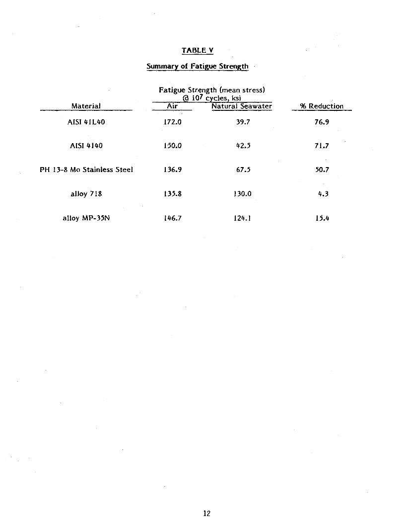
TABLE V
Material
AISI 41 L40
AISI 4140
PH 13-8 Mo Stainless Steel
alloy 718
alloy MP-35N
Summary of Fatigue Strength
FatiRue Strength (mean stress) - 107 cycles, ksi
Air Natural Seawater
172.0
150.0
136.9
135.8
146.7
39.7
42.5
67.5
130.0
124.1
% Reduction
76.9
71.7
50.7
4.3
15.4
12
ROTOR
1 \
1 1
NACELLE \ \
2--
\ '
ft
CONTROL CONE ANGLE BUI LOING
Figure 1. MOD-OA wind turbine.
13

C 0 0 Q) cn fn fn 0
.- c.
L
0 Q) -0 lu - m
c
E L
0
m Q a t) lu
c Y
-
- m
T Y
Q) Q)
c) +
.c
I I
v)
f x X 0 Q W
’I U 0
30
TI 3
cn CI
-
L
0
14
E-
O N
+I 0 v)
c)
?
"r
f 0 v
?
"r
+1 0 v)
0
C - Q CR C -
I 0 0 ; i n 2
f
15

16
4
L 3;
cn cn
1/20 sec --4
Minimum Stress / Maximum Stress = 0.6
Time *
Figure 5 . Diagram of fatigue cycle.
17

0 0 0 0 0 0 0 0 0 0 0 0 0
00 (0 * c4 0 cv d 0
l- v- F
edw ‘SSaJtS UeaW
0 0 0 0 0 0 0 0 0 0 0 0 0
00 (0 * c4 0 cv d 0
l- v- F
edw ‘SSaJtS UeaW
-0 F
18

0 d
d t-
f
I I I I 1 I I I 1 I I I I I
0 0 d t-
0 0 (u F
0 0 0 P
0 0 co
0 0 (D
0 0 d
0 8 (u
19

I I I I I I I I I I 1 I 1 I
0 0 w r
0 0 cv r
0 0 0 r
0 0 co
0 0 (0
0 0 *
0 0 OI
4 al
m 3
0 3: a) f
m r-l
cw 0
a)
20

0 0 0 0 0 0 0 0 0 0 0 0 0 0
cI( 0 a 4 0 e a e r l- r
k al 4J a
al rn E
h
21

k Q) U nl
a, m I4
%
0 0 cu r
0 0 0 r
0 0 Q)
0 0 <o
22
0 0 cu
SEM 277
Figure 11. Fractograph of corrosion fat igue specimen of PH 13-8Mo in seawater. Top left is f r ac tu re surface. Lower right is circumferential surface of fat igue specimen. Note pit t ing corrosion at f r ac tu re interface.
23

1. Reporl No 2. Government Accession No.
7 Key Words (Suggested by Author@))
Wind t u r b i ne; Ma t e r i a1 s Mod-OA p r o j e c t ; Environmental Test experience; Fatigue;.
NASA CR-174677 4. TI111 and Subtltle
18. Distribution Statement
Unclassi f i e d - un l i m i t e d STAR Category 44 DOE Category UC-60
Corros ion Fat igue o f High St rength Fastener Ma t e r i a1 s i n Seawater
9 Security Classl! (of this repor11 20 Security Classif. (of lhis page)
U n c l a s s i f i e d Uncl ass i f i ed
7. Author@)
21. No. of pages 22 Price'
- -- 26 A02
D. G. T ip ton
9. Performing Organization Name and Address
LaQue Center f o r Corros ion Technology, I nc . P. 0. Box 656 W r i g h t s v i l l e Beach, Nor th Caro l ina 28480
2. Sponsoring Agency Name and Address
U. S . Department o f Energy Wind Energy Technology D i v i s i o n Washington, D.C. 20545
5. Supplementary Notes
3. Recipient's Catalog No.
5 Report Date
December 1983 6. Performing Organlzatlon Code
8. Performing Organlzatlon Report No.
10. Work Unit No.
11. Contract or Grant No.
13. Type of Report and Period Covered
Contractor Rep0 rt 14. Sponsoring Agency CcdeRepOrt No.
DOE/NASA/0337-1
F ina l repo r t . Prepared under In teragency Agreement DE-AI01-76ET20320. P r o j e c t Manager, Richard K . Shal tens, Energy Techno1 ogy D i v i s i on, NASA Lewis Research Center, Cleveland, Ohio 44135.
6. Abstract
Environmental e f f e c t s can s i g n i f i c a n t l y reduce t h e f a t i g u e l i f e o f metals. As such, co r ros ion f a t i g u e i s a major concern i n t h e enqineer ing a p p l i c a t i o n of h i g h s t reng th fas teners i n marine environments. The co r ros ion f a t i g u e f a i l u r e of an AIS1 41L40 h i g h s t reng th s t e e l blade-to-hub attachment b o l t a t t he MOD-OA 200 kW wind t u r b i n e generator i n Oahu, Hawaii prompted the c u r r e n t t e s t program. Tests were undertaken t o con f i rm the dramat ic reduc t i on o f f a t i g u e s t reng th of AISI 41L40 i n marine environments and t o ob ta in s i m i l a r co r ros ion f a t i g u e da ta f o r candidate replacement ma te r ia l s . A I S I 41L40, AISI 4140, PH 13-8Mo s t a i n l e s s s tee l , a l l o y 718 and a l l o y MP-35N were tes ted i n a x i a l f a t i g u e a t a frequency o f 20 Hz i n d r y a i r and n a t u r a l seawater. The f a t i g u e da ta were f i t t e d by regres- s i o n equat ions t o a l l ow determinat ion o f f a t i g u e s t reng th f o r a g iven number o f cyc les t o f a i l u r e .
'For sale by the National Technical Information Service Springfield Virginia 22161