g-pon olt transceiver52ebad10ee97eea25d5e-d7d40819259e7d3022d9ad53e3694148.r84.cf3.rackc…g-pon olt...
TRANSCRIPT

G-PON OLT Transceiver
Page 1 of 6Coretek Opto Corp. 1F,10 Industry E. Rd. IV., Science-Based Industrial Park, Hsinchu, Taiwan, R.O.C. 08/06/2009http://www.coretek.com.tw Tel:886-3-5787871 Fax:886-3-5645105 Version:A
SFP BIDI, Single SC Connector, 1490nm DFB LD /1310nm APD, Power Budget 29.5dBDigital Diagnostics Functions
Applications Gigabit-capable Passive Optical Network
(GPON) OLT side. Gigabit Ethernet Point-to-Point Bi-directional
Transmission. Burst mode application. FTTx broadband access system.
Features TX:1490nm DFB LD CW Mode RX:1310nm APD burst Mode RX Upstream:1244Mbps, TX Downstream:2488Mbps Single +3.3V Power Supply RoHS Compliant and Lead-free LVPECL Differential Electrical Interface Compliant with Multi-Source Agreement (MSA)
Small Form Factor Pluggable (SFP) Compliant with SFF-8472 Digital Diagnostic
Monitoring Interface Single SC Connector Compliance with ITU-T G.984.2 GPON OLT Class B+ Fast Signal Detect Simplified OLT “reset” timing Eye Safety
Designed to meet Laser Class 1 comply withEN60825-1
DescriptionThe CT-2512TGP-JG5C-D from Coretek Opto Corp. is the high performance and cost-effective module for
serial optical telecommunication applications specified for single mode of TX 2488Mbps / RX 1244Mbps. Itoperates with +3.3V power supply. The module is intended for single mode fiber, operates at a nominalwavelength of Tx: 1490nm / Rx: 1310nm SC type SFP module. Each module is integrated with digital diagnosticsfunctions via an I2C serial interface.
The module is a single fiber connector transceiver designed for use in Gigabit-capable Passive OpticalNetwork (GPON) OLT applications. The transmitter is operating at continuous mode and the receiver is operatingat burst mode. The characteristics are performed in accordance with Telcordia Specification GR-468-CORE.
EMCMost equipment utilizing high-speed transceivers will be required to meet the following requirements:
1) FCC in the United States2) CENELEC EN55022 (CISPR 22) in Europe
To assist the customer in managing the overall equipment EMC performance, the transceivers have beendesigned to satisfy FCC class B limits and provide good immunity to radio-frequency electromagnetic fields.
Eye SafetyThe transceivers have been designed to meet Class 1 eye safety and comply with EN 60825-1.
PbRoHS

G-PON OLT Transceiver
Page 2 of 6Coretek Opto Corp. 1F,10 Industry E. Rd. IV., Science-Based Industrial Park, Hsinchu, Taiwan, R.O.C. 08/06/2009http://www.coretek.com.tw Tel:886-3-5787871 Fax:886-3-5645105 Version:A
Product InformationModel Number Operating Voltage
& SD Output Distance Wavelength Output Power Sensitivity
CT-2512TGP-JG5C-D 3.3V TTL AC/DC 20 km 1490 nm DFB / 1310 nm +1.5 ~ +5 dBm ≦-28 dBm
ABSOLUTE MAX RATINGSPARAMETER SYMBOL MIN MAX UNIT NOTE
Storage Temperature TS -40 85 ℃
Supply Voltage VCC 0 6 VData Input Voltage --- 0 Vcc VSupply Current IS 500 mA
OPERATING CONDITIONSPARAMETER SYMBOL MIN. TYP. MAX. UNIT NOTE
Case Operating Temperature TA 0 70 ℃
Supply Voltage VCC 3.1 3.5 VData Input Voltage Swing VID 300 1860 mV
ELECTRICAL CHARACTERISTICSPARAMETER SYMBOL MIN MAX UNIT NOTE
TransmitterTransmitter Supply Current ICCT 250 mADifferential Data Input Swing VID 0.4 1.6 VTx_ Disable Input Voltage - Low VIL 0 0.8 VTx_ Disable Input Voltage - High VIH 2.0 Vcc VTx_ Fault Output Voltage - Low VOL 0 0.8 VTx_ Fault Output Voltage - High VOH 2.0 Vcc VReceiverReceiver Supply Current ICCR 250 mADifferential Data Output Voltage VOD 0.4 1.3 VRx_ BRST_Det Output Voltage - Low VOL 0 0.8 VRx_ BRST_Det Output Voltage - High VOH 2.0 Vcc VMOD_DEF (1) , MOD_DEF (2) - Low VIL -0.6 Vcc × 0.3 VMOD_DEF (1) , MOD_DEF (2) - High VIH Vcc × 0.7 Vcc + 0.5 V
TRANSMITTER ELECTRO-OPTICAL CHARACTERISTICSPARAMETER SYMBOL MIN TYP. MAX UNIT NOTE
Optical Output Power Po 1.5 5 dBm 1Extinction Ratio ER 10 dBCenter Wavelength λc 1480 1490 1500 nmSpectral Width (-20dB) Δλ 1 nmSide Mode Suppression Ratio SMSR 30 dBRIN RIN -120 dB/HzOptical Rise time (20%-80% ) tr 160 ps 2Optical Fall time (20%-80% ) tf 160 ps 2Output Eye Compliant with ITU-T G.984.2

G-PON OLT Transceiver
Page 3 of 6Coretek Opto Corp. 1F,10 Industry E. Rd. IV., Science-Based Industrial Park, Hsinchu, Taiwan, R.O.C. 08/06/2009http://www.coretek.com.tw Tel:886-3-5787871 Fax:886-3-5645105 Version:A
RECEIVER ELECTRO-OPTICAL CHARACTERISTICSPARAMETER SYMBOL MIN TYP. MAX UNIT NOTE
Maximum Input Optical Power Pmax -8 dBm 3Minimum Input Optical Power Pmin -28 dBm 3Operating Wavelength λ 1260 1310 1360 nmOptical Return Loss ORL 14 dBDynamic Range DR 15 25 dBReceiver Electrical 3dB Upper Cutoff Frequency --- 1500 MHzBRST_Det - Asserted PA -28 dBmBRST_Det - Deasserted PD -45 dBmBRST_Det -Hysterisis 0.5 dB
Notes:1. Measured average power coupled into 9/125μm single mode fiber.2. These are 20-80% values.3. Measured with 223-1 PRBS at BER<10-10
TIMING CHARACTERISTICSPARAMETER SYMBOL MIN TYP. MAX UNIT NOTE
TX_DISABLE Assert Time TOff 10 μsTX_DISABLE Negate Time TOn 1 msTime to initialize, include reset of TX_FAULT TInit 300 msTX_FAULT from fault to assertion TFault 100 μsTX_DISABLE time to start reset TReset 10 μsRSSI Trigger Delay TTrigger 25 nsRSSI Sampling Time TRSSISample 300 nsInternal I2C Delay TI2C 500 μsRX BRST_Det Assert Time (off to on) TA,RX_SD 100 nsRX BRST_Det Deassert Time (on to off) TD,RX_SD 100 ns
BLOCK DIAGRAM OF TRANSCEIVER
G-PON OLT Transceiver
Page 4 of 6Coretek Opto Corp. 1F,10 Industry E. Rd. IV., Science-Based Industrial Park, Hsinchu, Taiwan, R.O.C. 08/06/2009http://www.coretek.com.tw Tel:886-3-5787871 Fax:886-3-5645105 Version:A
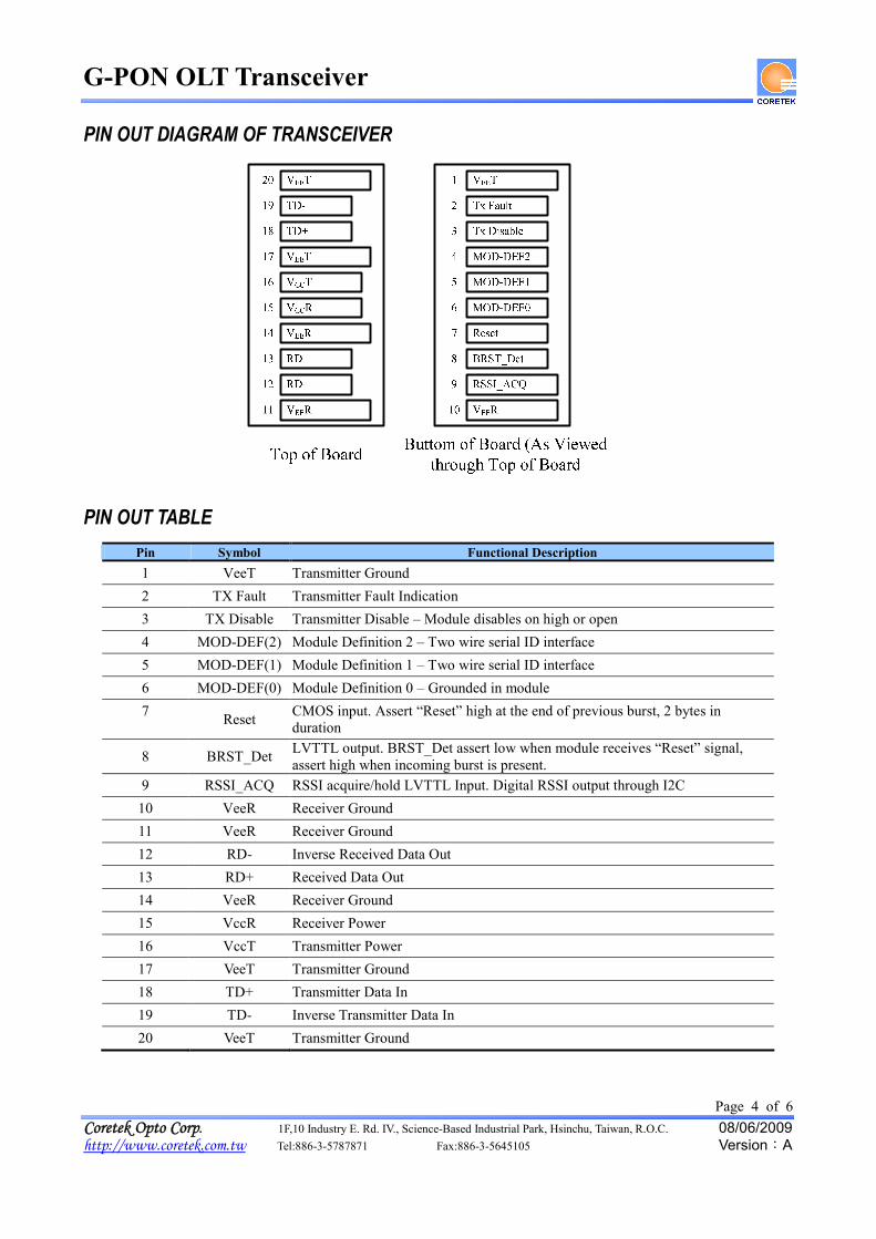
PIN OUT DIAGRAM OF TRANSCEIVER
PIN OUT TABLEPin Symbol Functional Description1 VeeT Transmitter Ground2 TX Fault Transmitter Fault Indication3 TX Disable Transmitter Disable – Module disables on high or open4 MOD-DEF(2) Module Definition 2 – Two wire serial ID interface5 MOD-DEF(1) Module Definition 1 – Two wire serial ID interface6 MOD-DEF(0) Module Definition 0 – Grounded in module7 Reset CMOS input. Assert “Reset” high at the end of previous burst, 2 bytes in
duration
8 BRST_Det LVTTL output. BRST_Det assert low when module receives “Reset” signal,assert high when incoming burst is present.
9 RSSI_ACQ RSSI acquire/hold LVTTL Input. Digital RSSI output through I2C10 VeeR Receiver Ground11 VeeR Receiver Ground12 RD- Inverse Received Data Out13 RD+ Received Data Out14 VeeR Receiver Ground15 VccR Receiver Power16 VccT Transmitter Power17 VeeT Transmitter Ground18 TD+ Transmitter Data In19 TD- Inverse Transmitter Data In20 VeeT Transmitter Ground

G-PON OLT Transceiver
Page 5 of 6Coretek Opto Corp. 1F,10 Industry E. Rd. IV., Science-Based Industrial Park, Hsinchu, Taiwan, R.O.C. 08/06/2009http://www.coretek.com.tw Tel:886-3-5787871 Fax:886-3-5645105 Version:A
TIMING DIAGRAM
Digital RSSI Acquire/Hold Timing Specification

G-PON OLT Transceiver
Page 6 of 6Coretek Opto Corp. 1F,10 Industry E. Rd. IV., Science-Based Industrial Park, Hsinchu, Taiwan, R.O.C. 08/06/2009http://www.coretek.com.tw Tel:886-3-5787871 Fax:886-3-5645105 Version:A
RECOMMENDED CIRCUIT SCHEMATIC
LDDriver
PreAmp
VEET
VCCT
VCCR
100
VCCT
RES
L1
L2
C1
C2
C3
Vcc
Tx Disable
Tx FaultRES
PostAmp
EEPROM
RD-
RD+
MOD-DEF(0)MOD-DEF(1)MOD-DEF(2)
Vcc
System130R
ES
RES
RES
RES
Vcc
BRST_Det
TD+
TD-
KRESKNote 107.4:HLL 12,1
FC 101FCC 1.03,2
50oZ
50oZ
50oZ
50oZ
ResetRSSI-ACQ
Vcc
82
MECHANICAL DIMENSIONSUnits in mm
All dimensions are ±0.2mm unless otherwise specified.Claim:
CORETEK Opto Corp. reserves the right to make changes in the specification described hereinafter without prior notice.