g-max - schletter north america g-max installation manual... · mounting instructions g-max ......
TRANSCRIPT

© Schletter Inc. | Updated 12/2017 | V2 | Subject to change without notice
1/16
Mounting instructions G-MAX™M
I-069
Contents
G-Max Mounting System ............................................................................................................................................................................ 2Tools Needed to Install G-Max Mounting System ............................................................................................................................. 3G-Max Configuration Options .................................................................................................................................................................. 4Foundation Post Installation ..................................................................................................................................................................... 5Mounting Individual Assembly Groups ................................................................................................................................................ 7Module Mounting ......................................................................................................................................................................................... 10Grounding Path .............................................................................................................................................................................................. 11Optional Accessories .................................................................................................................................................................................... 11Torque Specifications and Tolerances ................................................................................................................................................... 13Listing Requirement ..................................................................................................................................................................................... 13Equipment Grounding ................................................................................................................................................................................ 14Maintenance ................................................................................................................................................................................................... 14Safety Precautions......................................................................................................................................................................................... 14For More Information ................................................................................................................................................................................... 14Approved Module Manufacturers for Bonding and Grounding with Rapid5K™ clamps 2.0 .......................................... 15
G-Max
Purlins
Girder assembly
Foundation
5
3
4
1
Mounting instructions G-MAX
© Schletter Inc. | Updated 12/2017 | V2 | Subject to change without notice
2/16
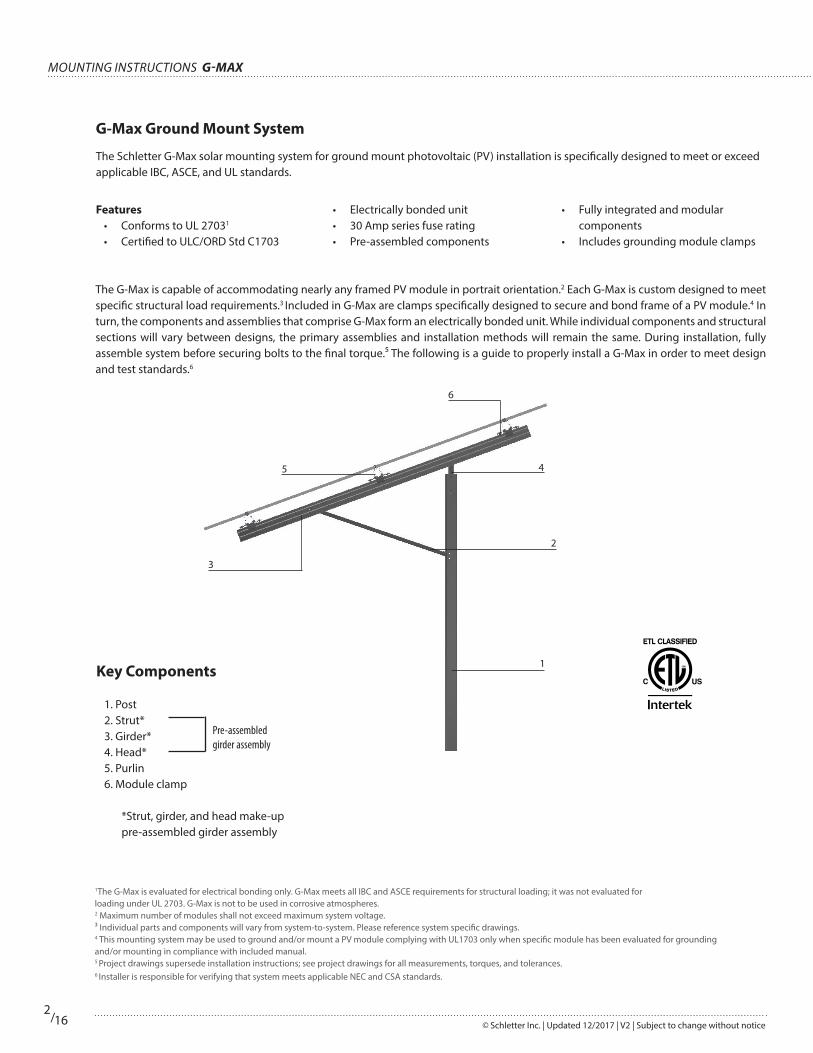
The Schletter G-Max solar mounting system for ground mount photovoltaic (PV) installation is specifically designed to meet or exceed applicable IBC, ASCE, and UL standards.
Features• Conforms to UL 27031
• Certified to ULC/ORD Std C1703
• Electrically bonded unit• 30 Amp series fuse rating• Pre-assembled components
• Fully integrated and modular components
• Includes grounding module clamps
The G-Max is capable of accommodating nearly any framed PV module in portrait orientation.2 Each G-Max is custom designed to meet specific structural load requirements.3 Included in G-Max are clamps specifically designed to secure and bond frame of a PV module.4 In turn, the components and assemblies that comprise G-Max form an electrically bonded unit. While individual components and structural sections will vary between designs, the primary assemblies and installation methods will remain the same. During installation, fully assemble system before securing bolts to the final torque.⁵ The following is a guide to properly install a G-Max in order to meet design and test standards.6
1The G-Max is evaluated for electrical bonding only. G-Max meets all IBC and ASCE requirements for structural loading; it was not evaluated for loading under UL 2703. G-Max is not to be used in corrosive atmospheres. 2 Maximum number of modules shall not exceed maximum system voltage.³ Individual parts and components will vary from system-to-system. Please reference system specific drawings.4 This mounting system may be used to ground and/or mount a PV module complying with UL1703 only when specific module has been evaluated for grounding and/or mounting in compliance with included manual.5 Project drawings supersede installation instructions; see project drawings for all measurements, torques, and tolerances.6 Installer is responsible for verifying that system meets applicable NEC and CSA standards.
Key Components
1. Post2. Strut* 3. Girder*4. Head*5. Purlin6. Module clamp
*Strut, girder, and head make-up pre-assembled girder assembly
Pre-assembled girder assembly
G-Max Ground Mount System
6
2

G-MAX Mounting instructions
© Schletter Inc. | Updated 12/2017 | V2 | Subject to change without notice
3/16
Tools Needed to Install G-Max Mounting System
Installation Tools
String line with wood line blocks for foundation post installation and purlin alignment
Permanent marker
Tape measure
Two (2) foot carpenter’s square for girder-to-purlin connection
Bubble level
A 9 mm, 16 mm, and 19 mm wrench and/or socket is required for all bolted connections
Torque wrench and Socket ExtensionA 9 mm deep socket is required for module installation using an M8 bolted connection or bottom-up clamp.
16 mm wrench and/or deep socket is required for all flanged M12 bolted connections at purlin clamps.
19 mm wrench and or deep socket required for all non-flanged M12 bolted connections at posts and purlin splice.
Ratchet and/or rechargeable power drill with controlled speeds
Torx® bit (TX40) for Rapid5K™ module clamps
Purlin Alignment Jig
TX40
Ensure all tools on checklist are assembled before starting installation.
19 mm
9 mm16 mm

Mounting instructions G-MAX
© Schletter Inc. | Updated 12/2017 | V2 | Subject to change without notice
4/16
G-Max Configuration OptionsThe G-Max Ground Mount System can be configured in a variety of ways based on project requirements. Below are some of the most common configurations and site designations.
• Direct Bolt Connection (Figure 1)• Rapid5K™ clamps (Figure 2)• Bottom Up Clamp (Figure 3)
Note: First Solar Module — see supplement for detailed information.
Direct bolt connection using bolts on first and third purlins and Schletter’s Rapid5K clamp on the middle purlin
Purlin includes small slots for direct bolt connection (shown as )
Figure 1a. — Direct Bolt
Figure 2a. — Rapid5K Clamp
Rapid5K clamp may be used to install all modules
Figure 1b. — Direct Bolt
Purlin includes long slots for Rapid5K clamp connection (shown as )
Figure 2b. — Rapid5K Clamp
Figure 3a — Bottom Up Clamp
Bottom up clamp may be used to connect modules from the bottom
Bottom up clamp, top down view in the long slot of the purlin (shown as )
Figure 3b — Bottom Up Clamp

G-MAX Mounting instructions
© Schletter Inc. | Updated 12/2017 | V2 | Subject to change without notice
5/16
• Review final drawing. Drawing will include information vital to proper installation of foundation posts.
• Refer to project drawing for tolerances for:• Embedment depth (Figure 6)• Support distance (Figure 7)• Lateral cantilever (Figure 7)• Post height variation (Figure 8)• Post verticality (Figure 9)• Post rotation (Figure 10)
• For longer racks, intermediate stakes may be required.
• Posts are installed vertically.• For East-West slopes greater than 5.7°
(10% slope) (Figure 11), contact your Schletter representative to discuss custom rack options. Racks can be designed for slopes up to 40° (84% slope).
Note: For G-Max Duo post, please see the supplemental instructions for additional installation instructions.
Foundation Post Installation
1. Survey Proposed Site
Embedment depth
Figure 6
Rotational tolerance
Figure 10
Average elevation difference between all posts
Figure 8
Lateral cantilever Support distance
Figure 7
Verticality tolerance
Figure 9
E-W slope tolerance
Figure 11

Mounting instructions G-MAX
© Schletter Inc. | Updated 12/2017 | V2 | Subject to change without notice
6/16
Position hydraulic ram and lift post into position beneath ram head
Hammer head touching top string line indicates correct depth is reached
2. Post Installation
• Position each post at respective installation locations based on completed stake-out.
• Advance post to embedment depth as shown on final drawing.
• Position string lines: bottom string line is used for correct placement of post; top string line indicates correct embedment depth: string is run from top of first post to top of first post of adjacent rack.
• When installing subsequent posts, ram until hammer head touches top string line.
• Upon completion of post pile drive, check that each post meets appropriate tolerances.
• If posts do not fall within tolerances, contact your Schletter representative. Notes:
• If post splice is required, see splice connection section for splice installation instructions.
• If after ramming post, there are signs of cracking, use 95% zinc paint to touch up post.
Use string line as guide to determine correct placement and depth of posts
Mark each post location using soil nails with flagging
Position posts on marked locations
Ram two posts at opposite ends of array for string line
• X

G-MAX Mounting instructions
© Schletter Inc. | Updated 12/2017 | V2 | Subject to change without notice
7/16
Mounting Individual Assembly Groups
Girder, strut, and head are pre-assembled for ease of installation and adjustability to ensure that specified tilt angle and clearance tolerances are maintained.
• Install location bolts (shown as 1 and 2); hand tighten to allow for installation of girder assembly.
• Position strut onto previously installed lower location bolt.
• Position head onto upper location bolt• Pivot girder until head and post align.• Secure girder assembly in place by
installing bolt at upper post. hole location (shown as 3).
• Check angle of girder and ground clearance; refer to construction drawings for measurement.
• Ground clearance is a reference dimension only and can be affected by adjustment to rack. See project drawings.
• Tighten post bolts using 19 mm socket. Notes:
• Multiple hole patterns are provided to ensure that specified tilt angle and ground clearances are maintained.
• Field installed bolts (shown as 1, 2 and 3) are to be installed snug tight7 and are NOT to be torqued!
• Factory installed bolts (shown as 4 and 5) have been factory installed to snug tight and should NOT be torqued!
Hand tighten location bolts on post (shown as )
7 Snug-tight is the condition that exists when all of the plies in a connection have been pulled into firm contact by the bolts in the joint, and all the bolts in the joint have been tightened sufficiently to prevent the removal of the nuts without the use of a wrench.
Connect head to foundation post
Connect strut to foundation post
1
2
5
4
1
2
3
Overview of Field Installed Bolts and Factory Installed Bolts: Bolts 1, 2, and 3 (shown as ) are field installed during the girder assembly installation and should be snug tight and NOT torqued. Bolts 4 and 5 (shown as ) are factory installed to snug tight and should NOT be torqued.
1. Mount Girder Assembly

Position purlin in purlin clamps
Torque purlin clamps as specified on project drawings using 16 mm socket
Mounting instructions G-MAX
© Schletter Inc. | Updated 12/2017 | V2 | Subject to change without notice
8/16
2. Mount Purlins
• Mount purlin to girder assembly starting with top purlin and working toward grade.
• Position purlin into lower purlin clamps. • Check that purlins are square to girder
using a carpenters square.• Purlin clamps should not be torqued
until racking is squared, prior to module installation; adjust as required.
• Tighten and torque purlin clamp to girder, while ensuring purlin stiffener is nested tightly.
• Tighten purlin clamps using 16 mm socket ensuring spring clip is properly oriented. Notes:
• Purlin must be mounted square to girder.
• The purlin cantilever and distances between purlins must be observed as specified in provided project drawing.
• Please consult project drawings for purlin orientation.
Mount purlin perpendicular to girder
Use a carpenter’s square to check that purlins and girder are square
• Consult system specific drawings for splice locations.
• Splice sleeve bolts should not be torqued until racking is squared prior to module installation adjust as required.
• Torque to specification with 19 mm socket. Refer to project drawings for torque values. Secure splice connection with M12x30 bolts and nuts
3. Splice Connection
Complete splice

Purlin alignment jig used to keep purlins square, align module clamp slots, and position splices
G-MAX Mounting instructions
© Schletter Inc. | Updated 12/2017 | V2 | Subject to change without notice
9/16
4. Purlin Alignment Jig
• Position purlins 1A — 1C on girder assemblies with accurate cantilever.
• Set jig into all purlins at position A (any clamp locations).
• Mount purlins 1A —1C to girder assemblies.
• Set jig into all purlins at position B with pins in purlin splices.
• Tighten purlin splice hardware.• Repeat above steps with
remaining purlins.
... ...
... ...
... ...
... ...
... ...
... ...
Purlin 1A
Purlin 1B
Purlin 1C
Position A Position B

Mounting instructions G-MAX
© Schletter Inc. | Updated 12/2017 | V2 | Subject to change without notice
10/16
21 mm
1. Position Modules
Module Mounting
2. Secure Modules• Do NOT use impact driver.• Verify that module clamp is fully
engaged on purlin and that module clamp is aligned with module frame.
• When mounting modules, please observe clamping points specified by module manufacturer.
• Install module clamps/hardware• Speed setting on power drill SHOULD
NOT EXCEED 1,000 rpm. Installation speed exceeding 1,000 rpm may damage clamp hardware.
• Torque clamps and hardware to specification.
Install clamps in purlin slots to secure modules
• Install clamps in purlin slots.• Purlins are positioned according to
module dimensions. • Rapid5K™ clamps 2.0 (referred to as
Rapid5K clamps) must be used on middle purlins.
Rapid5K mid clamp
1.5 mm maximum middle clamp to module offset
Nominal gaps between modules
Modules are positioned on purlins according to specified dimensions
3. Module Mounting Options
• Direct bolt connection• Bottom up clamp
Direct bolt connection using bolts on first and third purlins and Schletter’s Rapid5K Clamp on the middle purlin
Bottom up clamp may be used to install clamps from bottom
Mid Clamp
End ClampGrounding Clamp
Rapid5K end clamp Rapid5K grounding clamp

G-MAX Mounting instructions
© Schletter Inc. | Updated 12/2017 | V2 | Subject to change without notice
11/16
• Install bonding jumper on pre-punched holes at end of pulin using M12 bolt, washer, and M12 nut. Notes:
• Electrically bonds adjacent systems forming a continuous ground path.
• Connects directly to purlin.• Available in 12-inch lengths (additional
lengths available upon request).• Used for expansion joints or other
breaks in solar mounting system.• See electrical drawings for locations and
quantities of bonding jumpers.
1. Bonding Jumper
Optional Accessories
Install bonding jumper on pre-punched holes at end of purlin using M12 bolt, washer, and M12 nut
Grounding Path
Purlin
Module Frame
Grounding Clamp GirderHead
Post

Mounting instructions G-MAX
© Schletter Inc. | Updated 12/2017 | V2 | Subject to change without notice
12/16
• If cable management was ordered with system, connect before installing modules.
2. Cable Management
Stainless Steel Cable Tie*
• Install shim plates between post and splice tubing using 3/4” bolts, nuts, and washers. Notes:
• Splices are used to extend length of a post as needed.
• If post splices are required, attach using shim plates and provided hardware.
• Verify torque on all bolts.• Splice location will vary depending
on project.• Consult project specific drawings.
3. Post Splice
Install shim plates between post and splice tubing using 3/4” bolts, nuts, and washers (front view of post)
Loosen or remove top portion of grounding lug and insert grounding wire into appropriate groove
Grounding wire must extend through grounding lug by at least 1/4”
• Shares bolt that connects strut to post.• Remove serrated flange and install
grounding lug, torque to specification. See Project drawings for torque values.
• Accommodates stranded or solid copper wire (14 gauge to 2 gauge).
• Must use bare copper wire to connect to grounding lug. If using insulated grounding wire, remove at least two inches of insulation to expose copper wire.
4. Install Overcurrent Protection Device (grounding)
*Image courtesy of Heyco.
G-Hook cable management

G-MAX Mounting instructions
© Schletter Inc. | Updated 12/2017 | V2 | Subject to change without notice
13/16
Systems are specifically designed for each project. Please reference specific project drawing for allowable tolerances and recommended torque for each size of bolt used in the system.
In the event of deviation from approved drawings, contact Schletter immediately.
Torx Bolt for Rapid5K Module Clamps 13–15 N-M 10–11 FT-LBS
M6 and 1/4” Bolt 5–7 N-M 4–5 FT-LBS
M8 and 5/16” Bolt 13–15 N-M 10–11 FT-LBS
M12 and 1/2” Bolt 47–53 N-M 35–39 FT-LBS
M20 and 3/4” Bolt 232–256 N-M 171–189 FT-LBS
Label should appear on girder
• IMPORTANT! Listing requires that every girder be labeled.
• If girder has no label, contact your Schletter representative.
Listing Requirement
Torque Specifications and Tolerances
FRONT VIEWSCALE 1 : 10
SIDE VIEWSCALE 1 : 10
ASSEMBLY VIEWSCALE 1 : 6
PARTS LISTMASSMATERIALDESCRIPTIONPART NUMBERQTYITEM
SAE J2340Post, 8, Custom, Galvanized143008-00011 6105-T5Rail, DN0, Custom123001-001220.157 kg6105-T5Angle, 40x40, T=4, L=200, 2 Slots 41x11mm000009-555230.109 kg304 SSThreaded Rod, 3/8"-16 UNC, 304 SS, Grade B8, L=200mm119025-00200440.015 kg316 SSNut, Flange, Serrated, 3/8"-16 UNC, 316 SS943912-001850.013 kg316 SSNut, Square, 3/8" - 16 UNC, ASME-B18.2.2, 316 SS943919-126460.013 kg316 SSNut, Square, M10, DIN 557, 316 SS943914-010470.004 kg316 SSWasher, M10, DIN 125, 304 SS943921-010480.002 kgPolyamide (Nylon)KlickIn, M10129010-001490.024 kg304 SSScrew, Hex Head, M10x20mm, DIN 933, 304 SS943610-020410
1
1
2
2
3
3
4
4
A A
B B
C C
D D
MATERIAL:
DATEBY
SHEET: OF
TOLERANCES:
REVISION#
WEIGHT:
AREA:
PART NUMBER:CROWN:
TITLE / PROJECT / CUSTOMER:
RT PART #:
SIZE:
SCALE: AS SHOWNSUBCONTRACTOR:
ENG APPROVAL DATE:
ASSEMBLY NUMBER
CUSTOMER:
MFG APPROVAL DATE:
CREATION DATE:
CHECKED DATE:
DRAWN BY:
APPROVED:
STATUS:
CHECKED:
MFG:
Dillon.Hurley
WorkInProgress
8/5/2013
000000-000
Assembly Directions, Combiner Box Mount, M10
C
000000-000
1 1
OLD PART # :
kg/m or kg/sq m:
ISSUED BY: SCHLETTER INC. - PROPRIETARY AND CONFIDENTIALAll rights reserved. Reproduction of any kind only with the express, written consent of the Co: Schletter Inc.
239.0WIDTH ofCOMBINERBOX
27 9
3
6 41
5
5
8
10
LENGTH
LENG
TH
NOTE: 1. MAXIMUM COMBINER BOX PLUS CONTENTS WEIGHT = 100 lbs. PER KIT 2. PARTS LIST REFLECTS 2 KITS, AS SHOWN ABOVE
TORQUE: M6 AND 1/4" BOLT TORQUE IS 6 N-M (4.5 FT-LBS) M8 AND 5/16" BOLT TORQUE IS 14 N-M (10.5 FT-LBS) M10 AND 3/8" BOLT TORQUE IS 30 N-M (23 FT-LBS) M12 AND 1/2" BOLT TORQUE IS 50 N-M (37 FT-LBS) M16 AND 5/8" BOLT TORQUE IS 121 N-M (89 FT-LBS) M20 AND 3/4" BOLT TORQUE IS 244 N-M (180 FT-LBS)
Attach combiner box to foundation post. (SoloLT rail shown.)
• Thread 3/8” serrated flange nut to end of threaded rods with serrations directed toward SoloLT rail.
• Thread 3/8” square nut to end of threaded rods in front of serrated flange nut. • Slide 3/8” square nuts with threaded rod through square channel of SoloLT rail.• Hand tighten serrated flange nut to SoloLT rail. • Attach combiner box mount to post. Threaded rods should straddle post securing
aluminum angle to backside. Torque 3/8” serrated flange nuts to secure mount. • Press M8 Klickin and M8 square nut into Klick Channel of SoloLT rail. Adjust as
needed to for specific combiner box. • Attach combiner box using M8 socket head cap screw. M8 washer must be installed
under head of screw.
5. Combiner Box

Mounting instructions G-MAX
© Schletter Inc. | Updated 12/2017 | V2 | Subject to change without notice
14/16
Maintenance
• Yearly inspection of system should be conducted to maintain optimal performance.• Visually inspect for signs of damage, wear, corrosion, or movement. Replace any affected components immediately.• Check for loose wiring.• Maintenance should only be performed by qualified personnel.• Check mechanical details of structure:
• At least 2% of bolted connections must be checked using a calibrated torque wrench. The torque wrench must have a display or be a click type torque wrench.
• Torque wrench should be set at 50% of intended tightening torque. Check is successful if bolt cannot be loosened.• If >10% of checked bolted connections are loose, check has to be increased to 10% of all bolted connections.• If more than 10% of connections are still loose, all bolted connections much be checked.• Tighten all non-conforming bolts to specified torques • Requirements per ASME B107 and AISC
WARNING: Risk of death by electric shock. AVERTISSEMENT: Danger de mort par secousse électrique.
Safety Precautions
Follow proper installation and safety procedures at all times. Edges of parts may be sharp. Follow proper lifting procedures.
For More Information
For United States, visit www.schletter.us or call 888-608-0234 or for Canada, visit www.schletter.ca or call 519-946-3800 to speak to a Schletter representative for more information.
Equipment Grounding
• Many installations contain more than one mounting system. Such cases call for electrically bonding each of the different manufacturers systems. Since individual racks are fully bonded units, it is only necessary to connect individual racks together from one single point to another single point.8 Only use appropriate hardware when connecting harnesses or jumpers to the mounting system. Take care to prevent copper wires from directly contacting aluminum surfaces as this will cause corrosion. For this purpose, Schletter offers a bonding jumper (see page 11).
• The installer of Schletter’s electrically bonded G-Max must provide components necessary for the final connections to grounding electrode system. Typically installation will incorporate a grounding electrode (ground rod), appropriately sized copper wire, rated wire connectors, and grounding lugs which are rated for this purpose. The installer must follow all manufacturers’ installation literature. Installation must comply with all applicable NEC/CSA sections including but not limited to; NEC 250 (Grounding and Bonding), NEC 690 (Solar Photovoltaic Systems), CSA 22.1 (Safety Standard for Electrical Installations), and all other applicable state, and local electrical code requirements.
• Installer shall be fully responsible for all connections between Schletter’s bonded G-Max and PV grounding electrode system.• Equipment grounding conductors shall be no less than 14AWG (copper) or 12AWG (aluminum).• Equipment grounding conductors can be connected to any exposed metallic portion of rack system provided that:
• connection area is sufficiently sized• dissimilar metals are not in direct contact• connection does not interfere with other components• connection is protected from damage
• Calculation for overcurrent protection device including but not limited to spacing and wire size is the responsibility of installer.
8 Schletter recommends two bonding jumpers to connect separate systems for redundancy.Torx® is a registered trademark of Camcar Corp. division of Textron Industries.

G-MAX Mounting instructions
© Schletter Inc. | Updated 12/2017 | V2 | Subject to change without notice
15/16
Boviet Solar
BVM6610M-250|255|260|265|270
BVM6612M-300|305|310|315|320|325|330|335|340
BVM6610P-245|250|255|260|265|270
BVM6612P-300|305|310|315|320|325|330
Canadian Solar
CS6X-310|315|320P
CS6X-P-FG
CS6K-P-FG
CS6K-M
CS6K-M AB
CS6P-P
CS6P-P-SD
CS6V-M
ET Solar
ET-M660 285|280|275|270|265 BB
ET-M660 290|285|280|275|270
WW|WB
ET-M672 340|335|330|325|320 BB
ET-M672 345|340|335|330|325
WW|WB
ET-P660 265|260|255|250 BB
ET-P660 270|265|260|255 WW|WB
ET-P672 315|310|305|300 BB
ET-P672 320|315|310|305 WW|WB
Hanwha Q Cells
Q.PRO BFR G4|G4.1|G4.3
Q.PLUS BFR G4.1
Q.PRO G4
Q.PLUS G4
Q.PRO L G4.1
Q.PLUS L G4.1|G4.2
Q.PEAK-G4.1|G4.1/MAX
Q.PEAK BLK G4.1
Q.PEAK L G4.2
First Solar
Note: If using First Solar Modules, please see supplement
for additional information.
Series 4
Jinko Solar
JKM275P-60
JKM330P-72
Eagle 60|72
Eagle PERC
Eagle Black 60|72
JKM275PP-60-V
JKM330PP-72-V
JKM270P-60-V
JKM320P-72-V
Eagle MX JK07A|JK07B
JKM265PP-60
REC Solar
REC245|250|255|260|265|270PE
REC245|250|255|260PE BLK2
REC300|305|310|315|320PE72
REC265|270|275|280|285TP
REC330|335|340TP72
SolarWorld
Sunmodule SW 80 MONO RHA
Sunmodule SW 150 POLY R6A
Sunmodule SW 150 MONO R6A
Sunmodule SW 100 POLY RGP
Sunmodule Plus SW 280-295 MONO
Sunmodule Plus SW 285-300 MONO (5-busbar)
Sunmodule Plus SW 280-290 MONO BLACK
(5-busbar)
Sunmodule Plus SW 275-290 MONO BLACK
Sunmodule Pro-Series SW 260 POLY WOB
Sunmodule Protect SW 275-280 MONO BLACK
Sunmodule SW 320-325|340-350 XL MONO
SunPower
SPR-E19-320
SPR-E20-327
SPR-P17-355|350|345|340|335|330-COM
SPR-X21-345
SPR-X21-335-BLK
Trina
TSM-PD14
TSM-PD05
TSM-PD05.08
TSM-PD05.05
TSM-DD14A(II)
TSM-PEG5
TSM-PEG5.07
TSM-PEG14
TSM-PEG40.07
Yingli Green Energy
YL300C|295C|290C|285C|280C|275
C-30b
YL290D|285D|280D|275D|270D-30b
L340D|335D|330D|325D|320D|315D-
36b
YL275P|270P|265P|260P|255P|250P-
29b
YL260P|255P|250P|245P|240P-29b
YL325P|320P|315P|310P|305P|300P-
35b
Approved Module Manufacturers for Bonding and Grounding with Rapid5K Clamps

S C H L E T T E R G M B H H e a d q u a r te r s
Gewerbegebiet an der B15
Alustraße 1
83527 Kirchdorf / Haag i.OB
DEUTSCHLAND
S C H L E T T E R ( S h a n g h a i )
s o l a r te c h n o l o g y co. , l td
677 Beihe Gong Road
Jiading, Shanghai
201807 PR CHINA
S C H L E T T E R I n c .
1001 Commerce Center Drive
Shelby, North Carolina 28150
UNITED STATES
w w w. s c h l e t te r - gro u p. co m
i n f o . d e @ s c h l e t te r - gro u p. co m
SCHLETTER GMBH (Headquarters)Gewerbegebiet an der B15
Alustraße 183527 Kirchdorf / Haag i.OB
DEUTSCHLAND
SCHLETTER (Shanghai) Solar Technology Co., Ltd
677 Beihe Gong RoadJiading, Shanghai201807 PR CHINA
SCHLETTER Inc.1001 Commerce Center DriveShelby, North Carolina 28150
USA
For more information, contact a Schletter representative:
U.S.: (888) 608 - 0234Canada: (519) 946 - 3800