g e tti n g s ta r te d w i th p i x 4 d fo r a g r i c u
TRANSCRIPT

Getting Started with Pix4D for
Agriculture
3.3

Sign-up 3
Redeem 4
Hardware - Computer 4
Software Download and Installation 5 Download 5 Installation 5 Update 8
Hardware - Cameras 8
Inputs 9
Outputs 9
Image Acquisition Plan 9 General Case 10 Forest, dense vegetation areas and flat terrains with agricultural fields 11 Thermal 11 Multiple flights 11
Radiometric Calibration Targets 11 Environmental Flight Conditions 13
Processing Options Templates 13
How to create a project 14 Creating a New Project 14 Importing the Images 16 Configuring the Image Properties 17 Selecting the Output / GCP Coordinate System 18 Selecting the Processing Options Template 18
Processing Steps 19 1. Initial Processing 19 2. Point Cloud and Mesh 20 3. DSM, Orthomosaic and Index 20
Orthomosaic 20
Index Calculator 21 How to create a Region 21 How to create an NDVI Map 23 How to Export 25
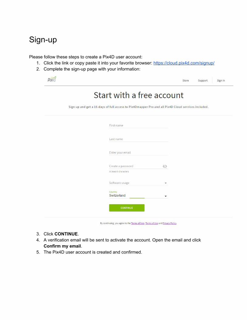
Sign-up Please follow these steps to create a Pix4D user account:
1. Click the link or copy paste it into your favorite browser: https://cloud.pix4d.com/signup/ 2. Complete the sign-up page with your information:
3. Click CONTINUE. 4. A verification email will be sent to activate the account. Open the email and click
Confirm my email. 5. The Pix4D user account is created and confirmed.

Redeem If the license is not already assigned to your account via an e-commerce purchase. The license redeem makes sure that you are the owner of your license. First, make sure that you have a Pix4D account. If not, create a Pix4D account as described in section Sign-up. The steps to redeem the license are:
1. Click the link under Activation Instructions in the License Certificate you have received when purchasing the Pix4D license.
2. Enter the license key in the box below:
3. Click Redeem and the license is under your account.
Note: To redeem a voucher bundled with a Sequoia camera, access the link at the bottom of the coupon you have received and the same procedure as above applies.
Hardware - Computer The following description shows the minimum and recommended Hardware and Software requirements: Minimum:
● Windows 7, 8, 10, Server 2008, Server 2012, 64 bits (PC or Mac computers using Boot Camp).
● Any CPU (Intel i5/ i7/ Xeon recommended). ● Any GPU that is compatible with OpenGL 3.2. (integrated graphic cards Intel HD 4000 or
above). ● Small projects (under 100 images at 14 MP): 4 GB RAM, 10 GB HDD Free Space.

● Medium projects (between 100 and 500 images at 14 MP): 8 GB RAM, 20 GB HDD Free Space.
● Large projects (between 500 and 2000 images at 14 MP): 16 GB RAM, 40 GB HDD Free Space.
● Very Large projects (over 2000 images at 14 MP): 16 GB RAM, 80 GB HDD Free Space. Recommended:
● Windows 7, 8, 10 64 bits. ● CPU quad-core or hexa-core Intel i7/Xeon. ● GeForce GPU compatible with OpenGL 3.2 and 2 GB RAM. ● Hard disk: SSD. ● Small projects (under 100 images at 14 MP): 8 GB RAM, 15 GB SSD Free Space. ● Medium projects (between 100 and 500 images at 14 MP): 16GB RAM, 30 GB SSD
Free Space. ● Large projects (over 500 images at 14 MP): 32 GB RAM, 60 GB SSD Free Space. ● Very Large projects (over 2000 images at 14 MP): 64 GB RAM, 120 GB SSD Free
Space.
Software Download and Installation At any given time there are two versions available to download:
● Pix4D Desktop: This version is meant for production work. ● Pix4D Desktop Preview: This version contains the newest features, but is not meant for
production work.
Download To download the software:
1. Go to: https://cloud.pix4d.com/download/. 2. Download Pix4D Desktop or Pix4D Desktop Preview.
Installation Once the software has been downloaded, install it using the following steps:
1. Double click the downloaded file. The Pix4Dmapper Setup wizard starts.

2. (optional): If the Open file - Security Warning pop-up appears, click Run.
3. In the Pix4Dmapper Setup pop-up, in the Welcome to the Pix4Dmapper Setup Wizard
screen, click Next >. 4. (optional) Click Browse... to change the destination path for the installation and click
Next >.
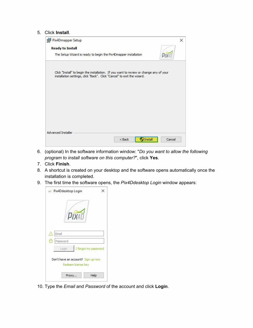
5. Click Install.
6. (optional) In the software information window: "Do you want to allow the following
program to install software on this computer?", click Yes. 7. Click Finish. 8. A shortcut is created on your desktop and the software opens automatically once the
installation is completed. 9. The first time the software opens, the Pix4Ddesktop Login window appears:
10. Type the Email and Password of the account and click Login.
11. Read the End-User License Agreement, select I accept the terms in the License Agreement and click Next.
12. Select one of these options: a. Request Pix4Dag now (Free Trial) to activate a 15-day trial. b. Use Pix4Ddiscovery to activate the limited version. c. Choose a license to select among existing licenses on the account.
13. Click OK. Pix4D Desktop is now ready for processing.
Update The newest Pix4D Desktop and Pix4D Desktop Preview versions are always available for download as described in section Download. Additionally, if a new version of Pix4D Desktop is available a Software Update pop-up with three options is displayed when the software is opened:
1. Download and Install Now to download and install the latest version available. 2. Remind Me Later to not download or install the latest version. The pop-up will appear
again in 10 days. 3. Cancel to not download or install the latest version. No reminder will appear.
Hardware - Cameras Cameras commonly used with Pix4Dag:
1. Multispectral cameras: (e.g. Parrot Sequoia, Airinov multiSPEC 4C, MicaSense RedEdge, ...) these cameras were designed for radiometric fidelity and typically provide the correct information to perform radiometric corrections.
2. Filter modified cameras: these cameras were not designed for agriculture purposes. They are not as accurate as multispectral cameras but with careful handling it is possible to obtain relative measurements. The choice of specific filters depends entirely on which band one is trying to measure and the indices that should be generated.
3. Thermal cameras: (e.g. Zenmuse XT, FLIR Vue Pro, Tau2-based sensor, …) to have enough visual content in the images for Pix4D software to reconstruct the scene, the minimum resolution is 640x480. Smaller sensors (320x256) are not recommended and typically do not calibrate.

Inputs The main input to Pix4Dag are images that can be either JPEG or TIFF files.
Warning: Do not modify the images, i.e. do not rotate or edit the images. Modifying images alters the geometrical properties of the camera and may deteriorate the quality of the results.
Extension Description
.jpg, .jpeg JPEG images
.tif, .tiff Monochromatic TIFF
Multi-band TIFF (RGB / Infrared / thermal)
1 layer (no pyramid, no multi-page)
8, 10, 12, 14, 16 bit integer, floating point
Outputs Pix4Dag can generate these outputs:
● Orthomosaic (GeoTIFF, KML file, Google Maps HTML file): 2D model (map) made by blending several orthophotos. Color balanced to be visually pleasing. The outputs are stored on this path in the results folder: ...project_name\3_dsm_ortho\2_mosaic.
● Index Map (GeoTIFF, Colored KML file, Grid Shapefile): To each index is associated an index map. For each pixel on this map, the value of the pixel is derived from the associated reflectance maps. The outputs are stored on this path in the results folder: ...project_name\4_index\indices.
● Video animation (.mp4, .mkv, .avi)
Image Acquisition Plan The image acquisition plan depends on the:
● Type of terrain / object to be reconstructed. ● Ground Sampling Distance (GSD): The GSD required by the project specifications will
define the distance (flight height) at which the images have to be taken. For example a

GSD of 5 cm means that one pixel in the image represents linearly 5 cm on the ground (5*5 = 25 square centimeters).
● Overlap: The overlap depends on the type of terrain that is mapped and will determine the rate at which the images have to be taken.
A bad image acquisition plan will lead to inaccurate results or processing failure and will require to acquire images again. All flight plans described below can be flown automatically with the flight planning app Pix4Dcapture available on Android and iOS.
General Case For most cases it is recommended to acquire the images with a regular grid pattern. The recommended overlap is at least 75% frontal overlap (with respect to the flight direction) and at least 60% side overlap (between flying tracks). The camera should be maintained as much possible at a constant height over the terrain / object to ensure the desired GSD.
The overlap and flight height have to be adapted depending on the terrain.

Forest, dense vegetation areas and flat terrains with agricultural fields For forest, dense vegetation areas and flat terrains with agricultural fields the same grid flight plan as in the General Case can be applied. However, it is recommended to increase the overlap to at least 85% frontal overlap and at least 70% side overlap and fly higher so that it is easier to detect similarities between overlapping images.
Thermal The same grid flight plan as in the General Case can be applied, but we recommend at least 90% frontal and side overlap with thermal images.
Multiple flights For projects with multiple flights there should be overlap between the different flight plans and the conditions (sun direction, weather conditions, etc.) should be similar. This could apply to a large field that needs to be covered in several flights.
Radiometric Calibration Targets The calibration target provides an absolute reference, and hence allows the computation of absolute reflectance values. The radiometric calibration target should reflect light equally in all directions (it should be a lambertian surface). The image of the calibration can be taken before, during or after the flight. It is important for the calibration image(s) to be taken in similar light conditions as the flight. If the images are taken during flying then the target should be large enough to be easily seen on the images.

If the Airinov Aircalib target is used the images of the calibration target can be added to the project along with other images and it will be automatically recognized as a calibration image. It is also possible to manually introduce the calibration image information. To manually introduce the calibration target images:
1. In the Menu bar, click Process > Processing Options. The Processing Options pop-up appears.
2. Click 3. DSM, Orthomosaic and Index. 3. Under Radiometric Processing and Calibration click the Calibrate button. 4. The Radiometric Calibration pop-up appears.
5. Import the calibration target image. 6. Draw a region on the image over the lambertian area of the target. 7. Set the Albedo values provided by the manufacturer. 8. Click OK.

Environmental Flight Conditions Flying close to sunrise or sunset is not advised. It is recommended to fly either in clear sky conditions or in fully overcast conditions, and for the light conditions not to vary drastically during the flight. The presence of strong wind will also adversely affect the reconstruction due to the motion of the plants.
Processing Options Templates These are the default Processing Options Templates available in Pix4Dag. We strongly recommend using these to process your projects.
Processing Options Template
Description
Ag Multispectral Outputs: reflectance, index (such as NDVI), classification and application maps. Typical input: aerial nadir images from multispectral cameras (Sequoia, Micasense RedEdge, Multispec 4C, etc). Outputs quality/reliability: high. Processing speed: slow. Application: precision agriculture.
Ag Modified Camera Outputs: reflectance, index (such as NDVI), classification and application maps. Typical input: aerial nadir images from modified RGB cameras. Outputs quality/reliability: high. Processing speed: slow. Application: precision agriculture.
Ag RGB Output: orthomosaic. Typical input: images from RGB cameras for agriculture (Sequoia RGB). Outputs quality/reliability: high. Processing speed: average. Application: digital scouting, report claiming for precision agriculture.

Ag Modified Camera - Rapid/Low Res
Faster processing of the Ag Modified Camera template for assessing the quality of the acquired dataset. Outputs quality/reliability: low. Processing speed: fast.
Ag RGB - Rapid/Low Res
Faster processing of the Ag RGB template for assessing the quality of the acquired dataset. Outputs quality/reliability: low. Processing speed: fast.
Thermal Camera Output: thermal reflectance map. Typical input: thermal cameras (Tau 2 based: FLIR Vue Pro, FLIR XT). Outputs quality/reliability: high. Processing speed: slow. Application: irrigation control, solar panels, building inspection, etc.
ThermoMAP Camera Output: thermal reflectance map. Typical input: nadir images taken with thermoMAP camera. Output quality/reliability: high. Processing speed: slow.
How to create a project This section goes step by step through the process of creating a new project. Example image datasets can be downloaded from the Pix4D Knowledge Base.
Creating a New Project To create a new project: 1. Start Pix4Dag. 2. On the Menu bar, click Project > New Project...

3. The New Project wizard opens:
4. In Name: type a name for the project. 5. (optional) In Create in: click Browse... On the Select Project Location pop-up, navigate to select the folder where the project and results will be stored and click Select Folder.
Warning: Ensure that:
● The project name DOES NOT use special character(s).

● The path where the project will be created DOES NOT use special character(s). ● The project name and the path together contain less than 128 characters.
6. (optional) Select the checkbox Use As Default Project Location to save all new projects in the selected folder. 7. In Project Type, keep the default option New Project selected. 8. Click Next.
Importing the Images On the Select Images window: 1. Click Add Images... to add the images.
2. On the Select Images pop-up, navigate to select the folder where the images are stored, select the images to be imported (it is possible to select multiple images), and click Open. 3. (optional) If a Sequoia and an Airinov Aircalib target are used, the images of the radiometric calibration target can be imported directly with the other images and they will be automatically recognized as calibration images. More in section Radiometric Calibration Targets. 4. Click Next.

Configuring the Image Properties There are 3 optional steps to follow before clicking Next: a. (optional) Select Image Coordinate System If the image geolocation is given in a coordinate system other than WGS84 (default), click Edit… under Coordinate System, and select the coordinate system of your images. b. (optional, recommended) Import Image Geolocation and Orientation If the image geolocation (position) information is stored in the EXIF of the images, it will be loaded automatically. Note: the geolocation information can also be imported from a file, by clicking From File....
Note:
● The software considers the Date Taken field of the EXIF to set up the order in which the images are taken.
● Step 1. Initial Processing is faster for projects with image geolocation. In the case of not sufficient overlap, image geolocation helps to calibrate the images.
c. (optional) Edit Selected Camera Model A camera model needs to be defined in order to run a project in Pix4Dag. The parameters of this model depend on the camera that was used to capture the image. Most cameras save their name in the metadata of the image in EXIF format. This field is used to associate a given camera model to all the images captured with this camera. The Selected Camera Model section, on the Image Properties window, displays the selected camera model. The camera model can be:
○ Valid: A green check is displayed if the camera model is valid. A camera model is valid if it already exists in the camera model database of Pix4Dag or if there is sufficient information in the EXIF data of the images to create a new camera model that will be saved into the user camera model database. If the camera model is retrieved from the EXIF data, it is recommended to check the camera model parameters and, if needed, to edit them.
○ Invalid: A red cross is displayed if the camera model is not valid. A camera model is invalid if it is not in the camera model database of Pix4Dag and if there is not enough information in the EXIF data of the images. In this case, the camera model needs to be defined manually.

Selecting the Output / GCP Coordinate System
In the Select Output Coordinate System window: 1. (optional) Change the Output / GCP Coordinate System.
Note:
● By default, the output and GCP coordinates system will be the same. Thereby, outputs can be shown in the coordinate system of the GCPs.
● By default, the Unit is m (meters). ● If the images have geolocation, by default, Auto detected is selected, displaying the
corresponding UTM or NAD83 zone of the images. ● If the images do not have geolocation, by default, Arbitrary Coordinate System is
selected.
2. Click Next.
Selecting the Processing Options Template
Ιn the Processing Options Template window: 1. Select the desired template based on the application and the desired outputs described in section Processing Options Templates.

2. (optional) Select the Start Processing Now box to automatically start the processing. 3. Click Finish to finish the wizard and start the project.
Processing Steps This section describes the three steps for processing with Pix4Dag.
1. Initial Processing In this step the images and additional inputs such as GCPs described in section Inputs will be used to do the following tasks:
● Keypoints extraction: Identify specific features as keypoints in the images. ● Keypoints matching: Find which images have the same keypoints and match them.

● Camera model optimization: Calibrate the internal (focal length,...) and external parameters (orientation,...) of the camera.
● Geolocation GPS/GCP: Locate the model if geolocation information is provided. Automatic Tie Points are created during this step. These are the basis for the next steps of processing. For more information about outputs, see section Outputs.
2. Point Cloud and Mesh This step will build on the Automatic Tie Points with:
● Point Densification: Additional Tie Points are created based on the Automatic Tie Points that results in a Densified Point Cloud.
● 3D Textured Mesh: Based on the Densified Point Cloud a 3D Textured Mesh can be created.
3. DSM, Orthomosaic and Index This step enables the creation of:
● Digital Surface Model (DSM): The creation of the DSM will enable the computation of Volumes, Orthomosaics and Reflectance Maps.
● Orthomosaic: The creation of the Orthomosaic is based on orthorectification. This method removes the perspective distortions from the images.
● Reflectance Map: The goal is to produce a map where the value of each pixel faithfully indicates the reflectance of the object.
● Index Map: Generate an Index Map where the color of each pixel is computed using a formula that combines different bands of the Reflectance Map(s).
Orthomosaic An Orthomosaic can be created with RGB images. To create an Orthomosaic:
1. Select the Ag RGB Processing Options Template in Process > Processing Options > Load Template.
2. Process steps 1 to 3. 3. The Orthomosaic output is located in the folder: ...project_name\3_dsm_ortho\2_mosaic
The Orthomosaic is created after step 3. DSM, Orthomosaic and Index is completed.
Note: The Mosaic Editor is not enabled, but the Orthomosaic output is located at ...project_name\3_dsm_ortho\2_mosaic.

Index Calculator The Index Calculator produces index maps very efficiently. The software will first produce a reflectance map for each measured band. Index maps can then be generated on a pixel-by-pixel basis.
How to create a Region A region enables the generation of Index Maps on an area of interest in the project. To create a region:
1. On the Index Calculator sidebar, in section 2. Regions, click Regions. The Region List pop-up appears.
2. Click Add. 3. (optional) Double click on unnamed to edit the name of the region. 4. Click OK. 5. Click on Draw to start drawing the polygon region in the Index View for the selected
region name.
In the Index View, left-click to place polygon vertices, and right-click to create the last
vertex and close the polygon. Ensure that after drawing a region, the check mark

appears beside the button Clear.
6. (optional) Click on Regions... to display the area of the regions and the percentage each
region occupies among all the regions.

How to create an NDVI Map For example, producing an NDVI map requires the reflectance data for the red and NIR bands since NDVI = (NIR-RED)/(NIR+RED).

In order to generate an NDVI Map: 1. On the Menu bar, click View > Index Calculator.
2. In the section 3. Index Map, select ndvi (this requires the red and NIR reflectance
maps to have been computed)
3. Click Generate 4. In the section 5. Export, click Export next to Colored Index Map (GEOTIFF) and
GeoJPG (JPG).
5. The exported Geotiff file can be found here: ...\project_name\4_index\indices\ndvi\ 6. (optional) Click Export next to Index Values and Rates as Polygon Shapefiles
(SHP) with Grid Size [cm/grid] to export a prescription map. The .shp file can be found here: ...\project_name\4_index\indices\ndvi\
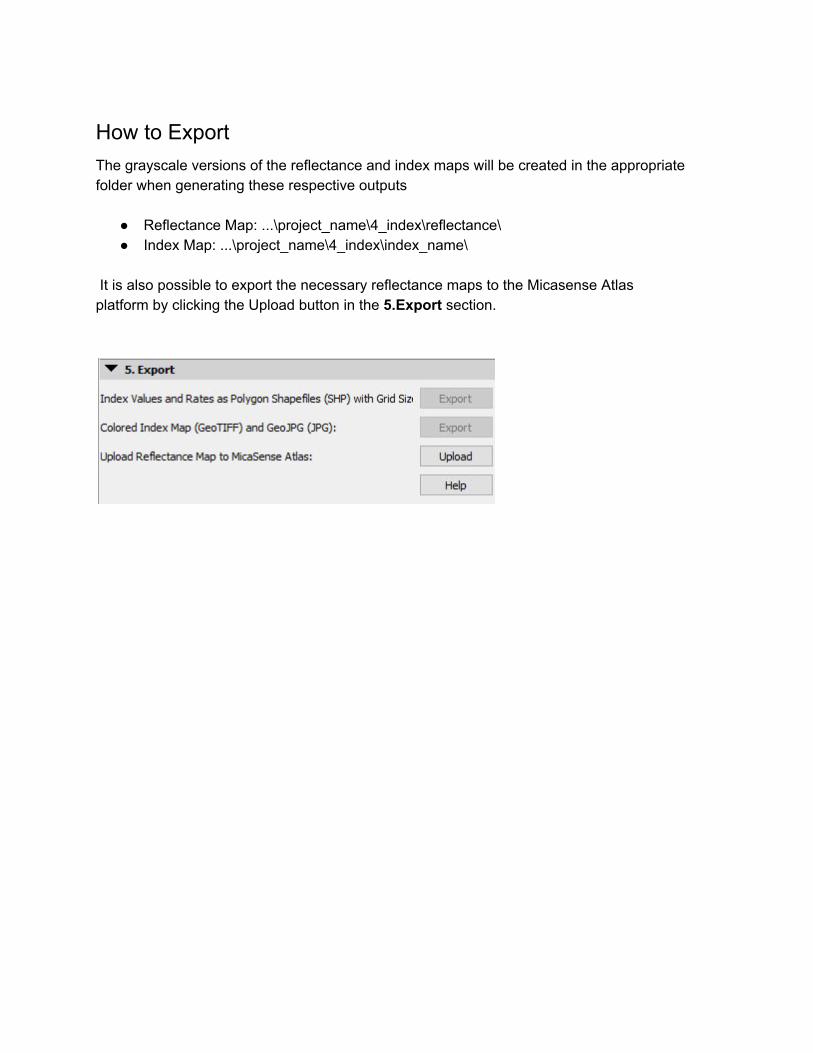
How to Export The grayscale versions of the reflectance and index maps will be created in the appropriate folder when generating these respective outputs
● Reflectance Map: ...\project_name\4_index\reflectance\ ● Index Map: ...\project_name\4_index\index_name\
It is also possible to export the necessary reflectance maps to the Micasense Atlas platform by clicking the Upload button in the 5.Export section.

www.pix4d.com