g. building performance rating method - thecat - web...
TRANSCRIPT
In addition to being used for code compliance, Standard 90.1 is often used as a baseline for energy efficient and green building programs. An example of such a program is the U. S. Green Building Council’s (USGBC) Leadership in Energy and Environmental Design (LEED) program. In addition, many utilities have incentive programs that offer financial incentives for buildings that are more energy efficiency than code minimum.
The purpose of the ECB modeling rules and procedures described in Chapter 11 is to provide an overall building performance rating procedure that has more flexibility than the options in the individual chapters, but is still workable for code compliance. Since the rules are intended for minimum code compliance, they purposefully limit the ability to trade-off the minimum prescriptive requirements. However, this is less of a concern and more flexibility can be provided when the purpose of the procedure is to show that a building is significantly better than code minimum.
To respond to the need created by LEED and utility programs, ASHRAE added informative Appendix G with the 2004 update to Standard 90.1. The procedures in informative Appendix G are intended to provide more flexibility and to give credit for measures such as building orientation, natural ventilation, daylighting, and HVAC system design and selection.
While the purpose of Chapter 11 is to provide a flexible path to code compliance and to minimize gamesmanship for trade-offs, the purpose of informative Appendix G is to establish a baseline for the entire energy consumption of the building to be used to calculate percentage energy
savings above this baseline. Appendix G gives credit for advanced design strategies and provides a standard procedure for rating the energy efficiency of the entire building.
The procedures in this chapter may be used with new buildings, additions to existing buildings and alternations to existing buildings. It may not be used, however, when the new or existing building has no mechanical system.
Terminology In Chapter 11, the terms Energy Cost Budget (ECB) and Design Energy Cost (DEC) are used. A building complies with the performance standards if the DEC is less than or equal to the ECB. For overall building performance ratings, the terms baseline building performance and proposed building performance are used instead. The goal with energy rating systems is to show that the proposed building performance is better than the baseline building performance by some given margin, the performance goal.
The rating authority is the entity with responsibility for administering and enforcing the building performance rating. Appendix G gives considerable responsibility to the rating authority. It determines if documentation is adequate and it sets procedures for reviewing and accepting calculations. Another role for the rating authority is to determine the baseline for components of energy use that are not directly addressed by Standard 90.1. The most notable examples of this are receptacle or plug loads. Table G3.1-12 states that the receptacle loads for the proposed building and the baseline building shall be the same, except as
specifically authorized by the rating authority.
How the Building Performance Rating Method is Different There are a number of important differences between the ECB Method and the building performance rating method. In general, the ECB Method is very limiting and is focused on minimum code compliance, while the building performance rating method is more comprehensive, far more flexible, and offers credit for a number of additional design measures and strategies.
The following are some of the key differences: ▪ The building performance rating
method includes the total energy consumption for all end uses. If neither Standard 90.1-2004 nor the rating authority set a baseline, then energy use shall be the same for both the proposed building and the baseline building (§ G1.2, § G3.9, § G4.5). ▪ Credit is offered for buildings that
have more favorable building orientation and buildings with poor orientation are penalized. ▪ Internal or exterior shades may be
modeled and credited in the proposed building if they are automatically controlled. ▪ Credit is offered for occupancy
sensors and programmable timers for lighting controls. These can be modeled by either modifying the lighting schedules or through power adjustment factors published in Appendix G. ▪ The rating authority may establish a
baseline for plug loads and a method of crediting more efficient equipment (§ G3.9). Plug loads are to be included in
G. Building Performance Rating Method
General Information (§ G1)
Building Performance Rating Method General Information
User’s Manual for ANSI/ASHRAE/IESNA Standard 90.1-2004 G-2
the simulations and in the calculation of savings. ▪ Users are allowed to “substitute a
thermodynamically similar component model” when the simulation tool can’t explicitly model a building feature. This will help with certain innovative systems, but especially underfloor air distribution (UFAD) and thermal displacement ventilation (TDV). ▪ Photovoltaic (PV) systems may be
modeled and credited in the calculations (Exception to G2.4). ▪ Credit is offered for energy efficient
fan systems. With the ECB Method, fan power is the same for the standard design and the proposed design. ▪ Some credit is offered for natural
ventilation for buildings that do not have cooling systems. ▪ More credit is offered for HVAC
system selection. With the ECB Method, the standard design depends in great part on the design of the proposed design, while with the building performance rating method, the approach is to specify the baseline system independently of the proposed design system.
Scope (§ G1.1) The building performance rating method is intended for rating purposes only. It is not an acceptable means of complying with Standard 90.1-2004.
The building performance rating method may be used for new buildings as well as alterations and additions to existing buildings. The only exception is for new buildings, alternations or additions that do not have a mechanical system. In this instance, the method may not be used.
Performance Rating (§ G1.2) With the building performance rating method, a computer program is used to calculate the annual energy operating cost
for both the proposed building and the baseline building. In the baseline building design, which is a variant of the proposed building, all mandatory and prescriptive requirements of the Standard are applied. In other words, the baseline building represents the building as if it were upgraded or downgraded to exactly comply with the Standard.
It is also necessary that the building be constructed to the efficiency levels modeled by the proposed design. This means that the efficiency of the individual components, the operation of the controls, and the overall design of the building must conform to the proposed design that was used to calculate the building performance rating. For this to happen, the building designers must accurately translate the energy assumptions used in the building performance rating calculations into the plans and specifications used to construct the building.
Mandatory Provisions (§ G1.2a) In spite of the building performance rating margin between the proposed building and the baseline building, the proposed building shall meet the mandatory provisions of Standard 90.1. These are contained in § 5.4, § 6.4, § 7.4, § 8.4, and § 9.4 of the Standard. The mandatory provisions are not available for trade-off. The mandatory provisions are needed for many reasons. ▪ Some of the mandatory provisions,
such as minimum motor efficiencies, are standard good practice and they should always be used. ▪ Some are difficult to accurately
model in a computer simulation, such as subdivision of feeders, and so their trade-off value cannot be accurately determined. ▪ Some specify calculation
methodologies needed to establish a fair
basis for comparison of components, such as U-factor calculations. ▪ Some Mandatory Provisions are not
intended for trade-offs, such as exterior lighting.
Calculating the Percentage Improvement The building performance rating method process involves comparing the proposed building performance to the baseline building performance and calculating the margin in terms of the percent savings. The annual energy operating costs is calculated for both the proposed building and the baseline building in a consistent and comparable manner. In making the comparison, the following rules apply:
1. Both runs (computer simulations) shall use the same simulation program.
2. Both runs shall use the same climate data.
3. Both runs shall use the same purchased energy rates.
4. Both runs shall use the same schedules of operation, except for adjustments needed to account for energy efficiency features.
These rules ensure a fair comparison
between the two runs, without introducing extraneous differences. For instance, if the runs used different simulation programs, then some portion of the differences between the resulting energy costs would be due to differences in algorithms or calculation methodologies. These differences could skew the determination of which building features are allowable under the Standard.
Similarly, if two different purchased energy rates were used, part of the difference between the runs would be due to rate differences. While this may be real in particular applications, it would introduce variations in the efficiency requirements for the building that are

General Information Building Performance Rating Method
User’s Manual for ANSI/ASHRAE/IESNA Standard 90.1-2004 G-3
inconsistent with the building performance rating method. Furthermore, due to the changeable nature of purchased energy rates, these differences may not last for the life of the building and so could skew the design of the building’s energy-related features. Individual building owners or designers may choose to optimize their buildings to take advantage of special rates, but building performance ratings require that the same rate be used for both runs.
Once the annual energy cost is known for both the proposed building and the baseline building, the savings percentage is calculated using the following equation.
Percentage improvement = 100 x (Baseline building performance rating - Proposed building performance rating) / Baseline building performance rating
Include All Energy Components Both the proposed building performance rating and the baseline building performance rating shall include all components of energy use, including receptacle loads, vertical transportation, garage ventilation, outdoor lighting, and process loads, such as refrigerated cabinets in supermarkets and clean rooms in laboratories. (Note that prior to the publication of Appendix G, rating programs did not always include all of the energy consumption in their comparison calculations.) Using less than the total energy consumption as a basis for comparison results in a higher percentage of energy savings. However, this is misleading to designers, building owners, and parties unaware of the basis for the comparison. They will hear percentage savings estimates and, unsurprisingly, construe this as applying to the total energy consumption or total energy cost of the building. As a result, confidence in energy savings estimates is undermined
when the actual results are less than expected.
Since Standard 90.1 does not set a baseline for receptacle loads, elevators, etc., it is the intent of the 90.1 committee that these components be identical in both the baseline and the proposed design unless others (the rating authority in particular) develop an appropriate baseline for these components and develop a procedure for calculating the savings related to these components.
Some components are considered non-interactive, meaning they have no significant interactions with the heating and cooling energy components. So as to provide a comprehensive picture and increase ease of evaluation, it is recommended that these components be included in the overall hourly analysis. Each of these non-interactive components can be input as a separate zone that has no envelope loads or HVAC serving it. The non-interactive component is then simply input as a peak load with a schedule. This way the calculations are all done automatically.
While less desirable, when allowed by the rating authority, the energy use of these non-interactive components can be determined in a side calculation and added to the simulation results—as long as the effect is included in the utility rate and energy cost calculations.
Other components with interactive energy uses need to be directly considered in each zone of the energy simulation since they contribute heat or have other thermal interactions with the space heating and cooling system. Examples include receptacle loads, computer rooms, refrigerated casework, and other interior process loads that contribute heat or remove heat from the space and therefore affect space heating and cooling loads.
Your Mileage May Vary It is important for users of the building performance rating method, as well as the owners of the proposed buildings, to understand the building performance rating method's intent and limitations. It is intended to provide a baseline for comparison of the estimated annual energy cost of the proposed building and the baseline building for purposes of a rating. It is not intended to provide an accurate prediction of actual energy consumption or costs for the building as it is actually built.
Although the energy analyst is expected to model energy use as closely as possible, there are many reasons why the actual building performance rating may differ from the predictions of the building performance rating method. These include: ▪ Variations in occupancy. The actual
schedules of operation and occupancy may differ from those assumed in the building performance rating analysis. ▪ Variations in control and maintenance.
The building’s energy systems may be controlled differently than assumed; the equipment may not be set up or maintained properly. ▪ Variations in weather. The simulation
runs use weather data that may not match the actual weather conditions for a given year. ▪ Changes in energy rates. The electricity,
gas, and other energy rates assumed in the calculations may change over time, resulting in higher or lower actual energy costs. ▪ Precision of the simulation program. Even
the most sophisticated simulation programs approximate the actual energy flows and consumption in a building; further, the energy analyst will usually make simplifying assumptions, such as combining zones with similar conditions. Both can be sources of deviations in the
Building Performance Rating Method General Information
User’s Manual for ANSI/ASHRAE/IESNA Standard 90.1-2004 G-4
predictions of energy cost and consumption.
The building performance rating method relies on the energy analyst and building designers to make reasonable assumptions for these factors, and the building performance rating results are expected to be reasonable predictions, especially since this is a comparative analysis and the proposed building and the baseline building use similar assumptions. However, it is clear from the points listed above, that even the best set of assumptions will likely lead to predictions that differ from actual building performance rating.
Trade-Off Limits (§ G1.3) Savings may not be based on promises about the future or on building improvements made in the past. Savings must be based on “real time” as defined by the current scope of improvements and documented in the construction documents.
This does not mean, however, that the project may not be phased; it can. The test is that the construction documents include all phases so that the energy analyst and the rating authority can verify pre- and post-conditions. .
For building additions, the designer has the choice of including the existing building in the calculation of the percent energy savings or excluding it. If the existing building is excluded, then Table G3.1-2 applies and the following conditions must be met: ▪ Any work to improve the existing
building must meet the prescriptive requirements and mandatory measures of Standard 90.1. ▪ The excluded portion for the
existing building was served by a separate HVAC system.
▪ Heat transfer between the new building addition and the existing building must be minimal. If party walls separate the new and existing portions, space temperatures and schedules of operation on both sides of the boundary shall be similar. ▪ If both the existing and new
construction areas are served by the same meter and the applicable utility rate includes ratchets, declining blocks, or other rate structures that are based on total energy consumption, the utility block or rate for the addition plus the existing building shall be used for the addition.
When the Building Performance Rating Method Can’t Be Used The building performance rating method may be used for just about any situation, but there are a few exceptions, as itemized below: ▪ No Mechanical System. When the
proposed building has no mechanical system, then the HVAC system for the proposed design shall be equal to the baseline mechanical system which is defined in terms of building size, number of floors, and building type (residential or nonresidential). ▪ No Envelope Design. New buildings or
additions that do not have an envelope design cannot use the building performance rating method. The building envelope must first be designed so that the building performance rating calculations can account for its characteristics.
In the case of a newly conditioned
space or a gut rehabilitation, where the existing envelope is not being changed or is not part of the permit, then the rules for alterations apply; the envelope would be modeled as-is and would be the same for both the proposed building and the baseline building.
Example G-A—Using the Building Performance Rating Method
Q I am making an addition to an existing building and last year, a new HVAC system was installed in the existing building. Can the baseline building include the pre-retrofit HVAC system and the proposed building include the improved system?
A No. Only systems proposed to be modified in conjunction with the addition may be considered in the analysis. Other features improved in the past, or proposed to be improved in the future must be the same for both the proposed building and the baseline building.
Q A proposed building has a 10,000 ft² parking lot, but the parking lot is not lighted. The Standard allows 0.15 W/ft² for parking lot lighting. Can the baseline building be modeled with a lighted parking lot, e.g. the proposed building is credited for not lighting its parking lot.
A No. End uses that do not exist in the proposed building cannot be added to the baseline building.

General Information Building Performance Rating Method
User’s Manual for ANSI/ASHRAE/IESNA Standard 90.1-2004 G-5
Documentation Requirements (§ G1.4) When the building performance rating calculations are submitted to the rating authority, the designers must include appropriate documentation. The documentation requirements are defined in § G1.4. The documentation should include the following: ▪ The annual energy cost of both the
baseline building and the proposed building should be documented along with the percent savings. ▪ The energy-efficiency features in the
proposed building that differ from the baseline building should be identified and clearly listed. It is necessary that the features be clearly described in the documentation, and that they be clearly indicated on the construction documents. For performance ratings, features such as favorable orientation, HVAC system selection, and reduced fan power may be listed since they are credited by the building performance rating system.
▪ Input and output reports from the computer simulation program should be provided. These reports should identify the components of energy use, which at a minimum should include: interior lighting, exterior lighting, service water heating energy (both electricity and gas), heating energy, cooling energy, fan energy, circulation pump energy, and other miscellaneous HVAC energy. All other energy end uses should be listed, even if Standard 90.1 does not provide a baseline. These numbers help to explain how the building is energy efficient and where the priorities for efficiency are found in the proposed building. In addition, the output reports must show the amount of time any loads are not met by the HVAC system for both the proposed design and the budget building design. If there is a substantial discrepancy between these two values, then the simulation models are not satisfactory (more detailed discussion of this issue follows). ▪ An explanation of any error
messages produced by the simulation
program. These messages indicate possible problems with the simulation models for the two designs, or they may simply indicate special conditions in the buildings. The burden is on the simulation modeler to explain which of these two conditions is indicated by each error message and to establish to the rating authority’s satisfaction that the models adequately demonstrate compliance under the building performance rating method.
It would be highly desirable for the
simulation engine to be coupled with software that automatically produces both the proposed building simulation and the baseline building simulation. Such software exists for use with some state and utility programs. Such software shells are also capable of producing the necessary documentation automatically and attending to other rules and procedures specified in Appendix G. At the time of this writing Appendix G has just been released and software shells as described above do not exist.
Building Performance Rating Method Simulation General Requirements
User’s Manual for ANSI/ASHRAE/IESNA Standard 90.1-2004 G-6
Performance Calculations (§ G2.1) Annual energy cost is calculated for both the proposed building and the baseline building using the same simulation program, the same weather data and at the same energy rates. These points are discussed in greater detail in the sections that follow.
Simulation Program (§ G2.2) At the heart of the building performance rating method are calculations done by the simulation program. In order to make sure that these calculations are sufficiently accurate for the purposes of the Standard, Appendix G establishes a series of requirements. The most basic requirement is that the simulation program be a computer-based program designed to analyze energy consumption in buildings, and that it have the capability to model the performance of the proposed building’s energy features. Building performance rating calculations are too complex for hand calculations, and there are many computer programs available that have the needed capabilities and are in widespread use. Examples include DOE-2, BLAST, and EnergyPlus, which were developed largely with public funds, and which are available to users in both public and private sector versions.
Several other proprietary programs also exist that have the minimum capabilities required by Appendix G. A listing of simulation tools that may be suitable for the building performance rating method can be found on the U.S. Department of
Energy’s web site at http://www.eren.doe.gov/buildings/tools_directory/.
Minimum Modeling Capabilities (§ G2.2.1) Section G2.2.1 specifies a minimum set of modeling capabilities for building performance rating method simulation programs. These requirements are broadly defined to allow all capable programs to be considered for approval by the rating authority, while eliminating programs that would not be able to adequately account for the energy performance of important building features. These minimum capabilities are: ▪ Minimum hours per year. Programs
must be able to model energy flows on an hourly basis for the full 8,760 hours during a year. Programs that use representative days for the different months and seasons are not permitted. ▪ Hourly variations. Building loads
and system operations vary hour-by-hour (or even for shorter durations), and their interactions have a great influence on building energy performance. Approved programs must have the capability to model hourly variations—and to establish separate schedules of operation for each day of the week and for holidays—for occupancy, lighting power, miscellaneous equipment power, thermostat set points, and HVAC system operation. ▪ Thermal mass effects. A building’s
ability to absorb and hold heat varies with its type of construction and with its system and ventilation characteristics. Mass may be located in exterior walls or other surfaces or interior to the space. Thermal mass
affects the timing and magnitude of thermal loads handled by the HVAC system. Simulation programs must be able to model these thermal mass effects. ▪ Number of thermal zones. All but
the simplest buildings have multiple thermal zones, with each zone experiencing different load characteristics. Approved programs must be able to model at least 10 thermal zones; many simulation programs can handle a far greater number. ▪ Equipment capacity and efficiency
correction curves. Mechanical equipment seldom operates continuously at full-load operating conditions or at the outdoor and indoor rating conditions, so the simulation program shall have the capability to model equipment under a variety of climate and part-load conditions. ▪ Economizers. Economizer
cooling is an important efficiency measure and is incorporated in the baseline building. Approved programs must have the capability to model air side economizers with integrated control. Integrated control means that the economizer model must be able to credit economizer cooling for meeting the cooling load even when it must work in tandem with the mechanical cooling system to do so. ▪ Baseline building design
characteristics. In addition to the general capabilities described above, simulation programs must have the capabilities to model the baseline building design, as specified in § G3. This is to ensure that the program can properly calculate the baseline building performance rating. Without this, percent savings calculations are not possible.
Simulation General Requirements (§ G2)

Simulation General Requirements Building Performance Rating Method
User’s Manual for ANSI/ASHRAE/IESNA Standard 90.1-2004 G-7
Proposed Building and Baseline Building Performance (§ G2.2.2) The simulation program shall have the capability to apply energy rates and calculate the proposed building and baseline building performance, as expressed in annual energy costs. Alternatively, the simulation program may produce hourly reports of energy use for each of the components (electricity, gas oil, propane, purchased steam, etc.) and the building performance rating for the proposed building and the baseline building may be calculated in a post-processing step.
Design Load Calculations (§ G2.2.3) The simulation program must be capable of performing design load calculations to determine required HVAC equipment capacities and air and water flow rates for both the proposed building and the baseline building. Calculations shall be based on generally accepted engineering standards.
Sizing calculations are needed to ensure that equipment in the baseline building is sized. For the baseline building performance rating, equipment shall be sized according to § G3.1.2.2, which over sizes cooling equipment by 15% and heating equipment by 25%.
Climate Data (§ G2.3) Climate data must be approved by the rating authority. The climate data must provide representative hourly values for all the relevant parameters needed by the simulation program, such as temperature and humidity. In addition, data on solar energy,
cloudiness, wind, etc., are often used by the programs.
Because the simulations are meant to represent the building’s long-term energy performance, it’s important that the climate data represent both average and design conditions. The average conditions alone are not sufficient because equipment-sizing calculations need data on design weather conditions.
Equipment sizing calculations may be performed using the hourly data or by using separate design data. When separate design data is used it must be developed using 99.6% heating design temperatures and 1% dry-bulb and 1% wet-bulb cooling design temperatures (see § G3.1.2.2.1).
There is frequently a need to apply engineering judgment in selecting climate data because weather stations having full data collection capabilities are not always located close to the proposed building site. In this case, the closest available weather station data should be used. Closest may not always mean geographic proximity, however. Major terrain features, such as elevation or proximity to marine conditions (the seashore), could affect the choice of the climate data set. The objective is to best approximate the weather conditions that will be experienced at the building site.
Energy Costs (§ G2.4) In addition to calculating energy use in the building, the simulation program must be able to calculate the energy cost, based on purchased energy rates. This may be done either directly within the program, or as a side calculation. If done as a side calculation, the program must be capable of producing hourly reports
of energy use by energy source, to which the approved purchased energy rates can be applied. This capability must be available for both the baseline building and the proposed building.
The energy analyst has some latitude to choose between different rates or rate structures that may be available for the proposed building, but the choice should best represent the purchased energy rates that will apply to the building over its lifetime.
There is a special case for calculating the energy cost for proposed buildings that have on-site renewable energy sources or site-recovered energy. For example, a building may have a solar thermal array, photovoltaic panels, or access to a geothermal energy source. Or a building with substantial refrigeration loads may recover heat from the condenser to meet service water heating loads. If the proposed building has either renewable or recovered energy, this energy is considered free energy by the building performance rating method, and that energy is not included in the proposed building performance rating.
The baseline building does not have on-site renewable energy sources or heat recovery, except as required by § G3.1.2.10 (exhaust air energy recovery) or Table G3.1-11b (condenser heat recovery for hot water). For the baseline building, the loads which are met by renewable or recovered energy in the proposed building are considered to be served by the backup energy source.
For example, where recovered energy is used to heat water (and this is not required by Table G3.1-11b), then the backup water heater would be assumed to supply all the hot water for the baseline building, and that cost

Building Performance Rating Method Simulation General Requirements
User’s Manual for ANSI/ASHRAE/IESNA Standard 90.1-2004 G-8
would be part of the baseline building performance rating. If no backup energy source is specified for the proposed building, then the source is assumed to be electricity in the proposed building design, and the approved purchased electricity rates are used to calculate that component of the baseline building performance rating.
This section of the User's Manual describes how the proposed building is created for the building performance rating method.
Exceptional Calculation Methods (§ G2.5) As newer technologies become available, there may be cases where none of the existing simulation programs can adequately model the energy performance of these technologies. The Standard allows the rating authority the discretion to approve an exceptional calculation method for use with the rating method. The nature of the exceptional
method is open-ended, but the burden is on the applicant to demonstrate that the method is reasonable, accurate, well founded, and not in contradiction with the rules of the building performance rating method.
The applicant must describe the theoretical basis for the exceptional method and must provide empirical evidence that the method accurately represents the energy performance of the design, material, or device. This documentation must also show that the method and its results.
1. Do not change the simulation program input parameters that are constrained by the building performance rating method or any other rules of the rating authority.
2. Provide adequate documentation for verification, including the assumptions and inputs to the method and the results and outputs of the method. The results must produce clear and consistent reporting of the required equipment and system features to enable
verification both on the construction documents and during field inspections. The documentation should also be consistent with the other documentation requirements established by the rating authority.
3. Provide instructions for the exceptional method, so that other users may apply it consistently and fairly in future rating method applications. Once approved, the exceptional calculation method will become, in effect, an amendment to the rating method. An example of a change in the simulation program might be a new algorithm for ground source heat exchangers or a credit for occupancy sensors. The rating authority is not discouraged from approving exceptional methods, but it should exercise judgment and care in approving them to ensure that they do not grant undue credit.
Calculation of the Proposed and Baseline Building Performance Building Performance Rating Method
User’s Manual for ANSI/ASHRAE/IESNA Standard 90.1-2004 G-9
Building Performance Calculations (§ G3.1) The proposed building energy cost is compared to the baseline building to determine the building performance rating. The energy cost of the proposed building and the baseline building are calculated as separate runs by an acceptable simulation program using the rules spelled out in Appendix G and this chapter.
The most important thing for a designer to understand about the building performance rating method is how the two simulation runs differ from each other; it is these differences that determine the margin of improvement between the proposed building and the baseline building. Many, if not most, of the inputs to the two simulation runs are identical. These identical building features and operational characteristics are “energy neutral,” i.e., they produce no energy credits or debits that could affect the energy performance rating. The features that are different may result in savings or increases in energy cost, and so these differences are the ones that determine the building performance rating margin.
This section discusses how energy costs are calculated for both the baseline building and the proposed building. The general rule for the baseline building run is that all inputs must be identical to the proposed design run, except for those features that are allowed to differ. This ensures that the two runs are comparable and that credit is given only for those features of the proposed building that will produce reliable energy savings over the life of the building.
Some ways of reducing unnecessary energy waste, which may be perfectly valid in the completed building, are not credited
under the building performance rating method. For example, building managers might operate a building at very low energy levels during off-hours when it is unoccupied. A designer may wish to take a credit for these savings by assuming more off-hour energy use in the baseline building than in the proposed building. These savings, however, may or may not actually occur and they are certainly less reliable than the savings from improved insulation or a more efficient lighting system. Under the building performance rating method, these latter improvements would be credited, but the hypothetical operational changes would not. Credits are available only when explicitly allowed by the building performance rating method.
For new buildings, the basic concept is that the baseline building be the same as the proposed building, except that each of the components is assumed to just meet the applicable mandatory provisions and the applicable prescriptive requirements of the Standard, as further defined in Appendix G and this chapter.
There is a distinction between the mandatory provisions and the prescriptive requirements. Section G1.2 states that the proposed building must always comply with the mandatory provisions. These mandatory provisions can never be traded off. However, credit can be taken for improvement over the minimum mandatory provisions (for example, mechanical equipment efficiency). The prescriptive requirements, on the other hand, become the criteria in the baseline building, but these are allowed to be traded off (for example, window SHGC). Of course, trading off any of the prescriptive measures means that even greater improvements will need to be made elsewhere to achieve a certain percentage energy savings.
Calculation of the Proposed and Baseline Building Performance (§ G3)
Example G-B—Applying Thermal Zones before Duct Design Completion
Q A permit has been applied for before the duct design has been completed. The interior partition walls are 25 ft from the exterior walls. How would the design and budget building thermal zones be applied?
A When the HVAC zones have yet to be designed, the perimeter thermal zones in the simulation will extend inward 15 ft from the perimeter wall regardless of partitions or interior walls. Figure G-E illustrates how the thermal zones and architectural zoning of the building differ.
Note that this 15 ft rule only applies to HVAC systems that have yet to be designed. When the HVAC zoning has been designed, the thermal zones in both the proposed building and baseline building should reflect the actual zoning.
Building Performance Rating Method Calculation of the Proposed and Baseline Building Performance
User’s Manual for ANSI/ASHRAE/IESNA Standard 90.1-2004 G-10
If the energy analyst chooses to use the addition plus existing approach, new system components in the existing building are assumed to meet the prescriptive requirements, while unchanged components are modeled at their existing levels of energy performance.
The following sections describe how the proposed and baseline buildings are derived for each of the major building systems.
Design Model (Table G3.1-1) The proposed building performance rating is calculated by the simulation program based on the proposed design, which is documented on the construction documents. For most new buildings, this is a straightforward exercise in modeling the building as it was designed, using good engineering judgment and the capabilities of the simulation program. All the building features shown in the design documents, including building size and shape, building envelope components and assemblies, lighting, water heating, and mechanical system equipment and controls, must be accounted for. The rules for calculating the proposed building performance rating in § G3 deal primarily with special circumstances and exceptions.
With the ECB Method it is only necessary to model regulated energy uses; however, with the building performance rating method, it is necessary to model all end-use load components within and associated with the building, including but not limited to, exhaust fans (also included in ECB calculations), parking garage ventilation fans, snow-melt and freeze-protection equipment, parking lot lighting, facade lighting, swimming pool heaters and pumps, elevators and escalators, refrigeration, and cooking.
Additions and Alterations (Table G3.1-2) For building additions, the designer has the choice of including the existing building in the calculation of the percent energy savings or excluding it. If the existing building is excluded, then the following conditions must be met. ▪ If there is any new work covered by
the Standard that is in a part of the existing building that will be excluded from the proposed design modeling, then those parts must comply with the Standard’s applicable mandatory and prescriptive requirements. ▪ The excluded parts of the existing
building must be served by HVAC systems that are completely independent of the systems or building components being modeled for the proposed building performance rating. ▪ There should not be any significant
energy flows between the excluded parts of the building and the modeled parts. In other words, the design space temperature, HVAC system operating setpoints, and operating and occupancy schedules on both sides of the boundary between the included and excluded parts must be the same. If the excluded portion of the building was a refrigerated warehouse and the included portion was an office, this condition would not be met, because there would be significant energy flows between them. ▪ If the included and excluded parts
of the building share the same utility meter, and if there is a declining block or similar utility rate used for the analysis, then the energy cost analysis must be based on the full energy use block for the building plus addition. This may be done either by modeling both the existing portion of the building plus the addition served by the utility meter, or by making an appropriate adjustment in the energy
cost calculation to account for the difference.
Space Use Classifications (Table G3.1-3) A key task in modeling the proposed design is assigning space use classifications to different areas of the building. These classifications are used to determine the lighting power for the baseline building and to differentiate areas within the building that may have different operating schedules and characteristics (thermostat settings, ventilation rates, etc.).
The choice of space use classifications is taken from one of the two lighting tables in the Standard: either Table 9.5.1 (the building area method) or Table 9.6.1 (the space-by-space method). The designer may choose either classification scheme but may not mix the schemes by using one for part of the building and the other for the rest of the building. The reasons for choosing one method over the other are discussed more fully in Chapter 9 of this Manual.
“Building,” in this context, refers to the space encompassed on the construction documents, which may be less than the complete building.
If the building area method is used for a mixed-use facility, the building may be subdivided into the different areas that correspond to the building types listed in Table 9.5.1. The secondary support areas associated with each of these major building types would be included in each building type. For example, if a building included both office and retail areas, the corridors and restrooms associated with the office occupancy would be included in the office area, and the storage and dressing room areas associated with the sales floor would be included in the retail area.

Calculation of the Proposed and Baseline Building Performance Building Performance Rating Method
User’s Manual for ANSI/ASHRAE/IESNA Standard 90.1-2004 G-11
Schedules (Table G3.1-4) The operating and occupancy schedules for the building and its systems have a large impact on the overall energy cost. The Appendix G allows designers, with the approval of the rating authority , to select reasonable or typical schedules for the building. In selecting the schedules, it is prudent to consider the likely long-term operation of the building. For example, if a new school will initially operate on a traditional schedule, but the school district has a policy of shifting its schools over to year-round operation, then it would be prudent to apply a year-round schedule in the modeling.
The selected schedules should likewise not intentionally misrepresent the operation of the building. If a grocery store chain keeps its stores open 24 hours a day, it would be inappropriate to use a 12-hour-a-day operating schedule in the modeling.
When appropriate, separate schedules should be used for weekday, Saturday, Sunday, and holiday schedules for each of the following: ▪ Occupancy; ▪ Lighting; ▪ Miscellaneous equipment power; ▪ Thermostat setpoints; ▪ HVAC system operation, including
system availability, fans, off-hour operation, etc; ▪ Any other significant loads or
equipment that could affect trade-off calculations including garage ventilation, outdoor lighting, etc.
Where the actual schedules are not
known, you may consult the values in Table G-E through Table G-N for guidance.
Occupancy schedules are used in a simulation to define a number of building conditions and loads. Schedules can include information such as the occupancy
level of a building, internal temperatures to be maintained and what percentage of equipment loads are “on” at a given moment. Schedules can vary significantly from building to building and tenant to tenant. Over the years a number of schedules have been defined using a variety of sources. The schedules given in Table G-E through Table G-N are based on ASHRAE Standard 90.1-1989, the last year schedules were included in this consensus document. They are reproduced in this chapter as an example of typical input data.
While engineers are often concerned with sizing equipment for the worst case load scenario, average conditions should be used for energy simulations. For example: electrical wiring is required to be sized for 3 watts per square foot of lighting load in a building. In actual practice lighting is typically half or less of that value, with many of today’s designs coming in at less than one watt per square foot. In addition, not all lighting is typically turned on at a given moment, so that the real load is only a fraction of what is used for wiring design. The same is true for building occupancy. The occupancy used for calculating emergency exiting requirements is considerable higher than the typical occupancy of the space. Be sure to review all schedules and peak loads against realistic expectations before using them in the simulation to make sure proper load levels are being included.
The schedules for the proposed building and the baseline building shall be identical, except as permitted by the rating authority. With the proposed building method (but not the ECB Method) it is possible to make changes or adjustments to the schedule to credit lighting controls, natural ventilation, demand control ventilation, and measures that reduce service water heating loads.
Schedules for HVAC fans must operate the fans continuously when the space is occupied. The only exception to this requirement is when the proposed building does not have a cooling system and the default system of the baseline building is used for the proposed building.
Building Envelope (Table G3.1-5) The basic rule for modeling the building envelope in the proposed building performance rating calculations is to use the design shown on the final architectural drawings, including building shape, dimensions, surface orientations, opaque construction assemblies, glazing assemblies, etc. In some cases, the building envelope may already exist, as in the case of newly conditioned space or a tenant build-out of a shell building; in these cases, the existing building envelope is modeled for the proposed building and these same conditions are assumed for the baseline building.
Any simulation program necessarily relies on a somewhat simplified description of the building envelope. It is usually too time consuming and difficult to explicitly detail every minor variation in the envelope design, and if good engineering judgment is applied, these simplifications won’t result in a significant decline in accuracy.
The following issues are explicitly addressed by the building performance rating method.
Uninsulated Assemblies All uninsulated assemblies shall be explicitly modeled. Examples include projecting balconies, perimeter edges of intermediate floor slabs, and concrete floor beams over parking garages.

Building Performance Rating Method Calculation of the Proposed and Baseline Building Performance
User’s Manual for ANSI/ASHRAE/IESNA Standard 90.1-2004 G-12
These uninsulated components perform significantly differently than insulated components and can represent significant energy losses. In addition, these uninsulated components are often concrete and have a thermal mass that is quite different from the light mass steel stud walls that are used as infill between the insulated components.
Projecting balconies and perimeter edges of intermediate floor slabs are considered part of the exterior wall area. While there may be more sophisticated methods of modeling these uninsulated assemblies, it is acceptable to model them as having the depth of the exterior walls they penetrate.
For example, if the wall between the intermediate floor slabs has a total depth
of 8 inches, then these assemblies can be modeled as being 8 inches thick. If the concrete slab that forms the projecting balcony or intermediate floor slab for a particular floor is 9 inches thick, then this section of the wall would be modeled in the proposed design as a 9 inch high uninsulated concrete wall that is 8 inches thick.
For the baseline building, this portion of the exterior wall would be considered a mass wall complying with the prescriptive requirements for the appropriate climate zone. The implication for the modeling is that a zone would have two wall types: a steel or wood frame type, and a mass wall type. See Figure G-A.
Lateral heat transfer may be ignored in the simulation, e.g. wall constructions can
be modeled as if heat from one section does not pass to the other.
This approach is also generally applicable to the edges of concrete floor slabs that separate parking garages from heated spaces above. Specifically, if the concrete floor slab is insulated below the slab (or not insulated at all), then the edges of the floor slab are considered part of the wall area and the bottom of the slab is considered part of the floor area. The only exception would be if the concrete slab floor was insulated above the slab. In this case, the edge of the floor slab would be beyond the conditioned area of the building and thus would not need to be insulated.
Except as noted in the previous paragraph, concrete floor beams over parking garages are considered part of the exterior floor area. Ideally, these beams would be completely wrapped with insulation. However, if the floor between the beams is insulated, but the beams themselves are not insulated, then the concrete beams are uninsulated components that need to be modeled separately.
Again, while there may be more sophisticated methods of modeling these uninsulated assemblies, it is acceptable to model them as having the thickness of the exterior floors they penetrate. For example, if the floor between the floor beams has a total thickness of 14 inches (including 1 inch of flooring material, a 9 inch floor slab, and 4 inches of rigid insulation), then these floor beam assemblies can be modeled as being 14 inches thick. If the concrete floor beam is 24 inches wide, then this section of the floor would be modeled in the proposed design as a 24 inch wide uninsulated concrete floor that is 14 inches thick. See Figure G-C.
For the baseline building, this portion of the exterior floor would be considered
Construction inProposed Building
Construction InSimulation Model
ProjectedConcreteBalcony
UninsulatedConcrete SlabEdge
Insulatedwall
ConcreteSame
ThicknessAs Wall
Figure G-A—Modeling Uninsulated Wall Conditions

Calculation of the Proposed and Baseline Building Performance Building Performance Rating Method
User’s Manual for ANSI/ASHRAE/IESNA Standard 90.1-2004 G-13
a mass floor complying with the prescriptive requirements for the appropriate climate zone. The implication for modeling is that a zone would have two floor types: a mass floor that is insulated, and a mass floor that is uninsulated. As with walls, lateral heat transfer may be ignored.
Note that the area of multiple uninsulated beams within the same zone can be combined for modeling purposes. (Also, see the discussion of Thermal
Blocks in Tables G3.1-7 through G3.1-9 for information on grouping HVAC zones into thermal blocks).
Minor Insulated Assemblies Frequently, there will be small areas on the building envelope that have unique thermal characteristics. Provided that these assemblies are insulated, the method allows any envelope assembly that covers less than 5% of the total area of a given assembly type (e.g., exterior walls or roofs)
to be added to an adjacent assembly of the same type with the same orientation and the same thermal properties. This is not intended, however to allow framing members in walls to be ignored just because they have an area less than 5%.
Clearly, a small portion of a steel frame wall insulated to R-15 could be combined with the predominant assembly where that wall is a steel frame wall with R-21 insulation. To model this overall steel frame wall correctly, an area-weighted average U-factor should be calculated that includes both the R-15 and the R-21 areas.
However, note that for example, if there is an exterior wall constructed of load-bearing masonry, with small wood-framed infill areas, the infill areas cannot be treated as if the entire wall is of masonry because the walls do not have the same thermal properties.
Note that the gross wall area is unchanged, and no areas are left out of the model. Despite this limited allowance to combine same type assemblies, it is still preferable and more accurate to model these minor assemblies. Modeling these assemblies separately also simplifies review and evaluations, as each assembly types can be directly traced back to a particular section drawing.
Different Tilt or Azimuth This exception, primarily intended to address curved surfaces, specifies the minimum number of orientations into which these surfaces must be split up. The Standard allows similarly oriented surfaces to be grouped under a single tilt or azimuth, provided they are of similar construction and provided that the tilt or azimuth of the surfaces are within 45 of each other. They may be grouped as a single surface or a multiplier may be used. The complex curved building plan shown on the left side of Figure G-E may be
Construction inProposed Building
Construction InSimulation Model
Concrete BeamIn Raised Floor
Raised ConcreteFloor With InsulationAbove
Insulation
Dashed LineRepresentsArea In Model
Raised ConcreteFloor With InsulationBelow
Figure G-B—Modeling Uninsulated Floor Conditions

Building Performance Rating Method Calculation of the Proposed and Baseline Building Performance
User’s Manual for ANSI/ASHRAE/IESNA Standard 90.1-2004 G-14
replaced with the much simpler pentagonal plan on the right with little loss in building simulation accuracy.
Reflective Roofs By default, exterior roof surfaces, other than those with ventilated attics, must be modeled assuming a surface reflectance value of 0.30. When a proposed design calls for a reflective roof surface, however, the model may assume a long-term average reflectance of 0.45, which credits the lower heat absorption of the reflective surface and makes a conservative allowance for degradation of the reflectivity over its lifetime. In order to qualify for this credit, the reflectance of the proposed design roof must exceed 0.70, and its emittance must exceed 0.75. Further, the reflectance and emittance values must be based on tests done in accordance with the following ASTM test standards: reflectance values shall be based on testing in accordance with ASTM E903, ASTM E1175, or ASTM E1918, and the emittance values shall be based on testing in accordance with ASTM C835, ASTM C1371, or ASTM E408.
Fenestration Shading Devices Manual fenestration shading devices such as blinds or shades shall not be modeled. Automatically controlled fenestration shades or blinds may be modeled. Permanent shading devices such as fins, overhangs and light shelves may be modeled.
Baseline Building Envelope The budget building design has the same physical shape characteristics as the proposed design, including: ▪ Same conditioned floor area; ▪ Same roof, wall, glazing (up to the
maximum allowable window-to-wall-ratio [WWR]), and other surface areas; ▪ Same surface tilts and orientations. For the building performance rating
calculations, the characteristics of these envelope components are set to the prescriptive values specified in Table G3.1-5. There are a few exceptions to these basic rules as described below.
Baseline Building Orientation The baseline building has the same surfaces area and orientations as the proposed building, but in order to credit
favorable building orientation and penalize poor building orientation, the baseline building is modeled in four orientations. The baseline building performance rating is taken as the average of the four results.
This is a significant difference between the building performance rating procedures and the ECB procedures. With the ECB procedures, if a designer is careful to properly orient windows for minimum solar gains, the energy budget buildings assumes the same orientation and there is no credit.
Many components of energy use will not change as the building orientation changes. These components include lighting (unless daylighting is explicitly modeled), plug loads, miscellaneous equipment, vertical transportation, exterior lighting, and water heating energy. However, HVAC energy can be quite sensitive to building orientation. Components of HVAC energy include heating, cooling, fans, pumps, and other equipment.
If the proposed building has a shape that shades itself during portions of the day, for instance a donut or “L” shaped building, the self-shading is ignored in the baseline building. Such features are credited to the proposed building when they are a benefit.
Baseline Building Opaque Assemblies The baseline building is assumed to be steel framed no matter what the construction of the proposed building. If the proposed building has thermal mass in the exterior construction and this is a benefit in a particular climate, then the mass is credited in the building performance rating method. Likewise, if the proposed building is wood-framed, there would be a benefit associated with fewer thermal breaks and a lower U-factor for the same amount of insulation.
Figure G-C—Simplifying Building Geometry for Energy Simulation

Calculation of the Proposed and Baseline Building Performance Building Performance Rating Method
User’s Manual for ANSI/ASHRAE/IESNA Standard 90.1-2004 G-15
The wall, roof, floor, slab and door constructions in the baseline building shall comply with the applicable prescriptive requirements for the following classes of construction: ▪ Roofs, insulation entirely above
deck; ▪ Above-grade walls, steel-framed; ▪ Floors, steel-joist; ▪ Opaque door types shall match the
proposed design and conform to the U-factor requirements from the same tables; ▪ Slab-on-grade floors shall match the
F-factor for unheated slabs from the appropriate climate specific table.
With the ECB Method, the class of
construction in the budget building is the same as the class of construction in the proposed building, while with the building performance rating method, the baseline building always is steel construction and a roof with insulation entirely above the deck.
For alterations to existing buildings, the baseline building shall conform to § 4.1.1.2 through § 4.1.1.4 of the Standard.
Baseline Building Vertical Fenestration Fenestration requirements apply to four areas:
Overhangs and Other Shading Projections The baseline building design is assumed to have glazing that is flush with the outside surface of the exterior wall surface. This means that the building performance rating method gives shading credit for window recesses, overhangs, side fins, or other permanent shading devices that reduce solar gains on the glazing, including self shading from the building itself. The baseline building is also assumed to have no interior shading devices, such as mini-blinds or curtains. However, the proposed
building may be modeled with interior or exterior shading devices as long as they are automatically controlled.
Fenestration Area The fenestration area in the baseline building shall be equal to the fenestration area in the proposed building or 40% of the exterior wall, whichever is less. If it is necessary to reduce window area in the baseline building, then corresponding increases are made in the opaque walls such that the gross exterior wall area is unchanged between the proposed building and the baseline building.
Fenestration area in the baseline building shall be distributed among the thermal blocks and around the building in a uniform manner. In each thermal block, the fenestration area shall be equal to the window wall ratio for the baseline building (the maximum of 40% or the proposed building WWR) multiplied times the exterior wall area for the thermal block. If the thermal block has more than one exterior wall, window area is placed proportionally on each.
The window area is positioned in continuous horizontal bands on each exterior wall, although the configuration of window area on each wall is not significant since neither daylighting or self shading from the building is modeled. See Figure G-D.
While the prescriptive envelope requirements provide an exception for street-level, street-side vertical fenestration (e.g., store display windows), the building performance rating method does not. Window area in the baseline building is always determined as described above.
Example G-C—Fenestration
Q I have designed a school according to the Collaborative for High Performance Schools (CHPS) guidelines with the majority of windows facing either south or north. Through careful site planning and building design, I have avoided windows facing east and west. The south-facing windows are also shaded by properly sized overhangs. Will these efforts be rewarded when I use the building performance rating method?
A Yes. With the building performance method, the baseline building has the same shape and orientation as the proposed design, but the baseline building is modeled four times. After the initial simulation, it is rotated 90, 180 and 270 degrees and the baseline building performance is taken as the average of these results. The south-facing overhangs are also credited, since the baseline building is modeled with no exterior shading devices and the windows flush with the outside surface of the exterior walls. Furthermore, if the building is configured in such a way that it is capable of shading itself (e.g. “L” or “U” shaped), this self shading is not modeled in the baseline building.

Building Performance Rating Method Calculation of the Proposed and Baseline Building Performance
User’s Manual for ANSI/ASHRAE/IESNA Standard 90.1-2004 G-16
U-Factors The fenestration U-factor in the baseline building is set to the minimum required for the climate and for the WWR of the baseline building, as specified in Tables 5.5-1 through 5.5-8 of the Standard. The minimum U-factor is a function of the baseline building glazing percentage, which is taken from the proposed design or 40% of the exterior wall, which ever is smaller.
SHGC The budget building design’s fenestration solar heat gain coefficient is set to the maximum required for the climate. The prescriptive standards give SHGC criteria for all orientations and provide an exception for north facing fenestration. The exception is not used for the baseline building; the criteria for all orientations are used for all orientations. The maximum SHGC is a function of the glazing percentage, which is taken from the proposed design or 40% of the exterior wall, which ever is less.
Baseline Building Skylights and Glazed Smoke Vents Skylights in the baseline building are defined in a similar manner as vertical fenestration. If total skylight area is less than or equal to 5% of the gross roof area, then area and configuration in the baseline building is identical to the proposed building. If the proposed building has skylights that exceed 5% of the gross roof area, then each skylight in the baseline building is reduced in size such that the total skylight area in the baseline building is exactly 5% of the roof area.
Orientation and placement of skylights in the baseline building is identical to the proposed building. The only difference is that they may be smaller if the skylight area in the proposed building exceeds 5%.
Example G-D—Baseline Building Model, Building Envelope
Q A proposed 400,000 ft² office building in New York City has a 60% window-to-wall ratio (see wall and window characteristics in the table below). The building entrance doors are glass and are included in the window area. There are 120 ft² of opaque swinging fire exit doors. How is the baseline building modeled?
A When the window area in the design building exceeds 40%, the window area in the budget building is set to 40% of the gross wall area and the opaque wall type for the baseline building replaces any window area that is removed. The opaque door area does not change. Thus the gross wall area (opaque wall + opaque door + window area) is the same for both baseline building and proposed building. The baseline building window area is distributed equally on each façade in horizontal bands. This means that some rooms that do not have windows in the proposed building will have windows in the baseline building. Since daylighting is not modeled in the baseline building, the position of the band of glass above the floor is not relevant. The baseline building uses the SHGC values for all orientations (the north facing exception is not used).
Proposed Building
Budget Building
Budget Envelope Properties
Gross wall area 400,000 ft² 400,000 ft²
WWR 60% 40% Maximum WWR Window area 240,000 ft² 160,000 ft²
Window type Fixed Fixed U = 0.57 Btu/h·ft²·°F
Fraction windows north 40% 40% North window area 96,000 ft² 40,000 ft² SHGC = 0.39
East window area 48,000 ft² 40,000 ft² SHGC = 0.39
South window area 48,000 ft² 40,000 ft² SHGC = 0.39 West window area 48,000 ft² 40,000 ft² SHGC = 0.39
Opaque door area 120 ft² 120 ft² U = 0.7 Btu/h·ft²·°F
Opaque wall area 159,880 ft² 239,880 ft² Wall type Concrete Steel frame U= 0.124 Btu/h·ft²·°F

Calculation of the Proposed and Baseline Building Performance Building Performance Rating Method
User’s Manual for ANSI/ASHRAE/IESNA Standard 90.1-2004 G-17
In terms of thermal and solar performance, fenestration in the baseline building shall have a U-factor and SHGC meeting the prescriptive requirements for the appropriate climate zone and condition. Separate prescriptive criteria are provided for three classes of skylights: plastic skylights (which are always assumed to be positioned on a curb), glass skylights on a curb, and skylights with no curb. For skylights, the curb is important because the U-factor considers heat losses through the curb as well as the glazing and the frame.
The fenestration U-factor and SHGC for the baseline building is based on the skylight class, which is the same for both the proposed building and the baseline building. If the proposed building has plastic skylights on a curb, then so does the baseline building. Likewise, if the proposed building has skylights on no curb, so does the baseline building.
Cool Roofs The reflectivity of roof surfaces affects solar heat gains and cooling loads. The building performance rating method allows credit for high reflectivity roof surfaces, provided they meet the requirements discussed above for roofs in
the proposed building, by requiring the baseline building design reflectivity to be set at 0.3 (30%) for all roofs.
Mandatory Provisions For the building envelope, the mandatory provisions are in Table G3.1-5. Some mandatory provisions worth highlighting follow. ▪ The roof insulation shall not be
installed on a suspended ceiling with removable ceiling panels (§ 5.8.1.8). ▪ Fenestrations ratings must be per
NFRC unless one of the default values is used (§ 5.8.2.1). ▪ Vestibules must be installed unless
the project qualifies for one of the exemptions (§ 5.4.3.4).
Again, remember that these mandatory
provisions are requirements that cannot be traded off. Any rated building must comply with these requirements.
Existing Building Envelope Conditions When the performance rating is determined for an addition with consideration of improvements to the existing building, the baseline building envelope shall represent existing conditions prior to construction.
Lighting (Table G3.1-6)
Proposed Building Lighting systems are a very important component of energy use for most nonresidential building types.
The building performance rating method builds upon the prescriptive lighting path in § 9.5 and § 9.6. Theatrical and other specialized lighting are exempt from the Standard but generate internal gains nonetheless. This exempt lighting must be modeled in both the proposed and baseline buildings in addition to the non-exempt lighting. It is the same, however between the proposed building and the baseline building.
If construction documents are complete, the proposed building lighting system power is modeled as shown on the design documents. If a lighting system already exists, then the proposed design is based on actual lighting power of the existing system and this power is also used in the baseline building.
In the special case where no lighting system or design exists, as in a shell building where the lighting will be installed by a future tenant, then a default lighting power must be assumed, based on the Building Area Method for the appropriate building type. If no building type is known, then an office building is assumed.
Lighting power shall include both permanently installed lighting systems as well as portable lighting systems, including individual task lights and furniture-mounted lighting.
Where certain automatic light controls are installed, lighting power in the proposed building may be adjusted by the power adjustment factors in Table G3.8. (Note that only one credit is allowed per space). Note that the adjustment factors vary depending on building size and hours of operation. Some automatic controls are
Proposed Building Baseline Building
Window AreaFrom Plans
Equal Glass AreaDistributed As Horizontal Blinds
Figure G-D—Horizontal Bands

Building Performance Rating Method Calculation of the Proposed and Baseline Building Performance
User’s Manual for ANSI/ASHRAE/IESNA Standard 90.1-2004 G-18
already required for buildings with 500 ft2 of conditioned floor area and larger. (Note that this threshold is for the entire building area, not the size of a tenant space. Thus a 200 ft2 tenant in a building with 7,500 ft2 of conditioned floor would not qualify for the credit). Having an automatic lighting control such as an occupancy sensor or an automatic time switch reduces the time that the lighting system operates, but it is also acceptable to estimate this effect by reducing the connected lighting power.
For buildings (not tenant spaces) less than 5,000 ft2 in conditioned floor area, a programmable timing control is estimated to reduce hours of operation by 10% and may be estimated by reducing connected lighting power by 10%. Remember that energy equals power times time, so a 10% reduction in either is equivalent. For buildings larger than this, the lighting requirements already require an automatic control, so this feature must be modeled in both the proposed building and the baseline building and no credit is allowed.
Occupant sensors alone or a combination of occupancy sensors and programmable timing controls have a 15% power adjustment factor for daytime occupancies and buildings less than or equal to 5,000 ft². The power adjustment factor is 10% for all other buildings.
Another way to take credit for automatic lighting controls that are not part of the baseline is to make an adjustment in the lighting schedule. This approach may be appropriate for daylighting controls, occupancy sensors and other types of controls. However, the burden is on the energy analyst to show that the schedule adjustment is warranted. Documentation may include supplementary daylighting calculations, monitored data from similar buildings or other evidence.
Baseline Building Lighting System The interior lighting power density (LPD) for the baseline building shall be determined using one of the two methods. Either the building area or space-by-space method may be used, but the categorization of spaces must be identical between the proposed building and the baseline building.
The LPD for the proposed design is taken from the design documents for the building. The LPD specified in the models must correspond to the spaces within each thermal block.
Any interior lighting system efficiency improvements or reductions in the proposed building are reflected as credits or debits in the building performance rating method.
Under the Standard, required lighting controls (primarily automatic shutoff controls) are modeled using the lighting schedules. No additional automatic lighting controls (e.g., programmable controls or automatic controls for daylight utilization) shall be modeled in the baseline building design, as the lighting schedules used are understood to reflect the mandatory control requirements in the Standard.
Daylighting controls are not modeled in the baseline building model but may be modeled in the proposed building model. Ideally, these controls would be modeled with an hourly energy analysis program that contains an algorithm that assesses and responds to the daylighting received in the space for each hour.
If the proposed building has automatically controlled shading devices, then these may be modeled to reflect realistic assumptions about occupants closing blinds and drapes when direct sunlight creates too much glare. No interior blinds or drapes are modeled if the proposed building does not have automatic control.
Modeling of the controls should also reflect whether all the lamps in a fixture are dimmed together and step-switched on and off one by one. If there are any areas of the building for which the lighting systems are not defined, then those areas are modeled using base LPDs for both the proposed and budget runs (based on the building area method), and their lighting systems are energy neutral for the building performance rating.
The proposed building may include power adjustment credits for occupant sensors or automatic time switches (when they are not already required by the mandatory provisions). Adjustments to the lighting schedule may also be included in the proposed building to capture savings from daylighting or other lighting controls, but these adjustments are subject to the approval of the rating authority.
Exterior lighting is included in the building performance rating calculations. For exterior grounds lighting, the lighting efficacy must be a minimum of 60 lumens per watt for both the proposed building and the baseline building.
Other than cases where the lighting is exempted, credit may be taken for improvements in exterior lighting efficacy or wattage. If the proposed building does not have an exterior lighting application (for instance a parking lot that is not lighted), the baseline building shall not have the exterior lighting application either. If the lighting application exists, however, then the proposed building can take credit for a more efficient system .
Mandatory Provisions For lighting, the mandatory provisions are described in § 9.4. Some mandatory provisions worth highlighting are: ▪ Automatic shutoff for lighting in
buildings larger than 5000 ft2 (§ 9.4.1.1, exceptions to § 9.4.1.1);

Calculation of the Proposed and Baseline Building Performance Building Performance Rating Method
User’s Manual for ANSI/ASHRAE/IESNA Standard 90.1-2004 G-19
▪ Automatic shutoff for exterior lighting (§ 9.4.1.3, exception to 9.4.1.3); ▪ Separate controls for display lighting
(§ 9.4.1.4a); ▪ Master/control device for lighting in
hotel/motel guest rooms (§ 9.4.1.4c); ▪ Tandem wiring for three-lamp
ballasts (§ 9.4.2); ▪ Maximum wattage for exit signs
(§ 9.4.3). Again, these mandatory requirements
cannot be traded off.
Thermal Blocks—General Discussion The building performance rating method distinguishes between HVAC zones and thermal blocks. An HVAC zone is physically determined by the design of the HVAC system. It includes some number
of thermodynamically similar spaces whose loads can be satisfied through use of a single thermostat (or other type of temperature control). A thermal block is a simulation program term. It is similar to an HVAC zone, except that often in simulation practice a number of zones, which have similar loads and are served by similar systems, are combined into a single thermal block for modeling purposes.
Grouping HVAC zones into thermal blocks requires engineering judgment to avoid modeling errors, but when it is done reasonably, there is no significant loss of accuracy. For example, the interior HVAC zones of a multi-story building may be physically separate zones on each floor, but they may often reasonably be combined into a single thermal block in the simulation model of the building because they have similar loads and are served by similar systems. However, a cafeteria or computer room in an office building would need to be modeled separately, as would lower-floor retail uses. The basic rule of the proposed building rating method is that thermal blocks must be defined identically for the proposed building and the baseline building. This is consistent with the rule that the shape and area of the building envelope for the baseline building design be the same as for the proposed building, that the space use classifications be the same, and so forth.
Thermal Blocks—HVAC Zones Designed (Table G3.1-7) HVAC zones may be combined into thermal blocks for modeling purposes (or multipliers may be used) when all the following conditions are met:
1. All of the space use classifications are the same . This ensures that they have the same load and schedule characteristics.
2. For exterior HVAC zones with glazing, the glazing for all zones included in the thermal block must have the same orientation, or at least their orientations must be within 45 degrees of each other. This ensures that they have approximately the same solar heat gain characteristics. This is not to say that the zones may not have two or more glazing orientations—a corner office could easily have two—but that the zones must have similar orientations. It would be acceptable, for example, to group all of the northeast corner offices on the intermediate floors of an office tower into a single thermal block.
3. All of the HVAC zones in the thermal block must be served either by the same HVAC system or by the same kind of HVAC system. This is so that the simulation program can accurately model the performance of the system(s) serving the block.
Thermal Blocks—HVAC Systems Not Designed (Table G3.1-8) When HVAC zones are not designed at the time of the building performance rating, then the configuration of the thermal blocks must be assumed (Table G3.1-8b). This situation is quite common in commercial buildings where the future tenants will determine the zoning of spaces in the building. In this case, thermal blocks must be defined based on similar internal load densities, occupancy, lighting,
Figure G-E—Thermal Zoning in
Building Simulation When the HVAC Zones Are Not Yet Designed
X 10 x 2x 5
x 5x 2
Actual Building Simulation Model Figure G-F—Thermal Blocks for Apartment Building
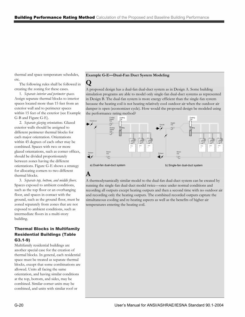
Building Performance Rating Method Calculation of the Proposed and Baseline Building Performance
User’s Manual for ANSI/ASHRAE/IESNA Standard 90.1-2004 G-20
thermal and space temperature schedules, etc.
The following rules shall be followed in creating the zoning for these cases.
1. Separate interior and perimeter spaces. Assign separate thermal blocks to interior spaces located more than 15 feet from an exterior wall and to perimeter spaces within 15 feet of the exterior (see Example G-B and Figure G-E).
2. Separate glazing orientations. Glazed exterior walls should be assigned to different perimeter thermal blocks for each major orientation. Orientations within 45 degrees of each other may be combined. Spaces with two or more glazed orientations, such as corner offices, should be divided proportionately between zones having the different orientations. Figure G-E shows a strategy for allocating corners to two different thermal blocks.
3. Separate top, bottom, and middle floors. Spaces exposed to ambient conditions, such as the top floor or an overhanging floor, and spaces in contact with the ground, such as the ground floor, must be zoned separately from zones that are not exposed to ambient conditions, such as intermediate floors in a multi-story building.
Thermal Blocks in Multifamily Residential Buildings (Table G3.1-9) Multifamily residential buildings are another special case for the creation of thermal blocks. In general, each residential space must be treated as separate thermal blocks, except that some combinations are allowed. Units all facing the same orientation, and having similar conditions at the top, bottom, and sides, may be combined. Similar corner units may be combined, and units with similar roof or
Example G-E—Dual-Fan Duct System Modeling
Q A proposed design has a dual-fan dual-duct system as in Design A. Some building simulation programs are able to model only single-fan dual-duct systems as represented in Design B. The dual-fan system is more energy efficient than the single-fan system because the heating coil is not heating relatively cool outdoor air when the outdoor air damper is open (economizer cycle). How would the proposed design be modeled using the performance rating method? Cooling
Coil
Heating Coil
Zone1
Zone2
Zonen
Supply Fan
Return Fan Exhaust
air
Outsideair
MixingBox
MixingBox
MixingBox
CoolingCoil
HeatingCoil
Zone1
Zone2
Zonen
CoolingSupplyFan
ReturnFanExhaust
air
Outside air
MixingBox
HeatingSupplyFan
MixingBox
MixingBox
a) Dual-fan dual-duct system b) Single-fan dual-duct system
A A thermodynamically similar model to the dual-fan dual-duct system can be created by running the single-fan dual-duct model twice—once under normal conditions and recording all outputs except heating outputs and then a second time with no outdoor air and recording only the heating outputs. The combined recorded outputs capture the simultaneous cooling and re-heating aspects as well as the benefits of higher air temperatures entering the heating coil.

Calculation of the Proposed and Baseline Building Performance Building Performance Rating Method
User’s Manual for ANSI/ASHRAE/IESNA Standard 90.1-2004 G-21
floor loads may be combined (see Figure G-F).
HVAC Systems (Table G3.1-10)
Buildings With Incomplete Energy System Design Some buildings, such as retail malls and speculative office buildings, typically are built in phases. For example, the core mechanical system may be installed with the base building, while the ductwork and terminal units are installed later as part of tenant improvements. A similar situation can occur with the lighting system or with the building’s other energy-related features.
For the purpose of calculating the proposed building performance rating, the rule is simple: future energy features that are not yet designed or recorded in the construction documents are assumed to minimally comply with the applicable mandatory provisions and prescriptive requirements. In cases where the space use classification is not known, the default assumption is to classify it as office space using the building area method.
Requirements for both Heating and Cooling The building performance rating method, and indeed the rest of the Standard, is based on the assumption that buildings are heated and cooled. Even if not installed initially, it is common for buildings lacking a heating or cooling system to have one retrofitted by future occupants.
Accordingly, there is a special rule for calculating the proposed building performance rating when a building’s HVAC system is heating-only or cooling-only: the building must be modeled as if it had both heating and cooling. The missing system is modeled the same as the baseline
building (defined later in this chapter). The same system is modeled for both the proposed building and baseline building simulations.
This requirement only applies to conditioned spaces in the building. Semiheated spaces would only have a heating system; unconditioned spaces would have neither heating nor cooling systems.
The proposed building default cooling system does not exclude natural ventilation from consideration. It just means that the proposed building is modeled as a “hybrid system” where cooling is provided by natural ventilation when conditions are acceptable and by the default mechanical cooling system when natural ventilation is inadequate to provide thermal comfort.
HVAC Systems The HVAC system in the proposed building design shall be that shown on the construction documents if the system has been designed. The basic rule for modeling HVAC systems for the proposed building is to base the model as completely as possible on the actual system design as shown in the construction documents. This includes the system type, equipment capacities and efficiencies, controls, ancillary features (such as economizers), etc. The equipment efficiencies may need to be adjusted to meet the needs of the simulation program. While efficiencies may be most accurately specified at the building’s design conditions, most simulation programs require efficiencies to be specified at standard rating conditions, such as those given in § 6.4.1 of the Standard. If that is the case, than the efficiency values needed by the simulation program should be used in the modeling.
Some special cases related to HVAC systems need to be considered:
1. A complete HVAC system exists. An example might be an existing speculative building that is being built out for a tenant. The variations in the performance rating would be limited to the interior construction and lighting system. In a case like this, the proposed building and baseline building models are the same and are based on the existing HVAC system.
2. No heating system exists. If no heating system exists, a default heating system must be assumed and modeled for the proposed building. The system should be electric and equal to the baseline building definition, which is defined later in this Chapter.
3. No cooling system exists. If no cooling system exists, a default cooling system must be assumed and modeled. It shall be identical to the system in the baseline building, as defined later in this Chapter.
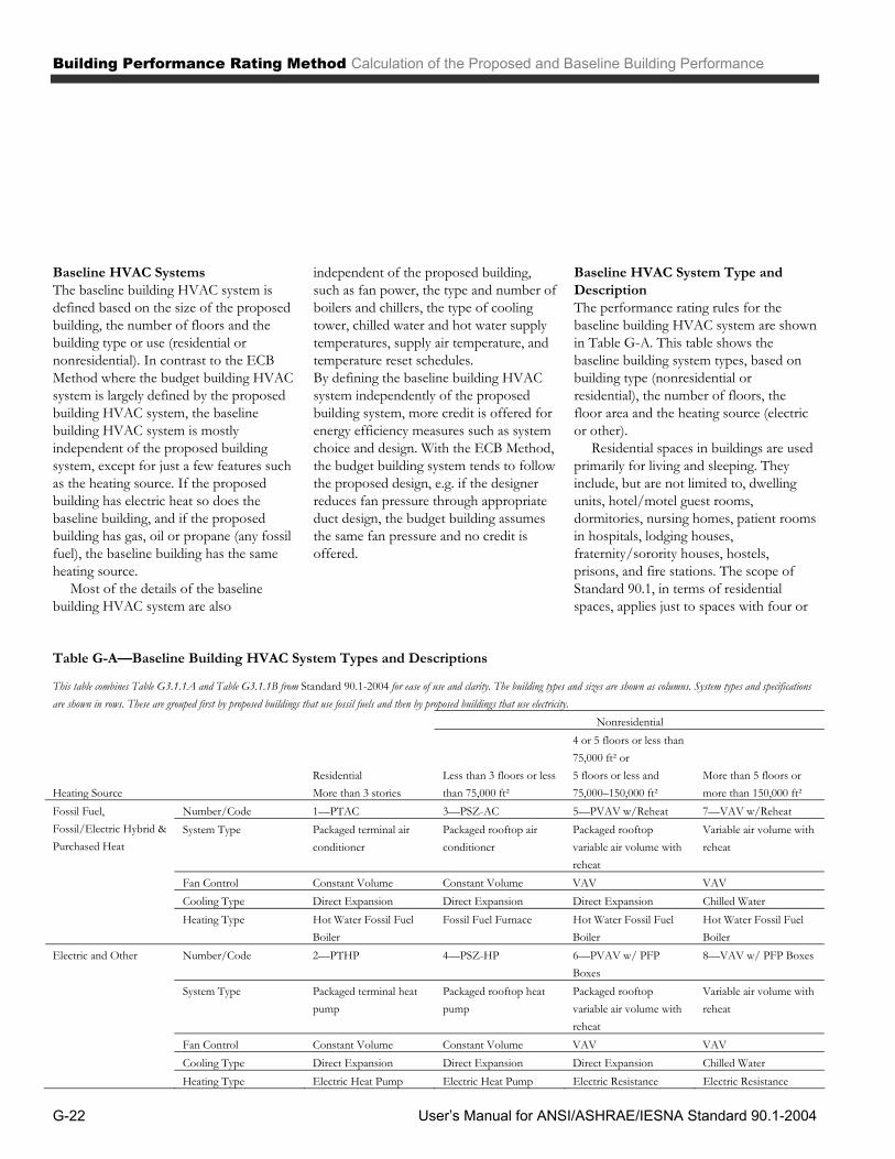
Building Performance Rating Method Calculation of the Proposed and Baseline Building Performance
User’s Manual for ANSI/ASHRAE/IESNA Standard 90.1-2004 G-22
Baseline HVAC Systems The baseline building HVAC system is defined based on the size of the proposed building, the number of floors and the building type or use (residential or nonresidential). In contrast to the ECB Method where the budget building HVAC system is largely defined by the proposed building HVAC system, the baseline building HVAC system is mostly independent of the proposed building system, except for just a few features such as the heating source. If the proposed building has electric heat so does the baseline building, and if the proposed building has gas, oil or propane (any fossil fuel), the baseline building has the same heating source.
Most of the details of the baseline building HVAC system are also
independent of the proposed building, such as fan power, the type and number of boilers and chillers, the type of cooling tower, chilled water and hot water supply temperatures, supply air temperature, and temperature reset schedules. By defining the baseline building HVAC system independently of the proposed building system, more credit is offered for energy efficiency measures such as system choice and design. With the ECB Method, the budget building system tends to follow the proposed design, e.g. if the designer reduces fan pressure through appropriate duct design, the budget building assumes the same fan pressure and no credit is offered.
Baseline HVAC System Type and Description The performance rating rules for the baseline building HVAC system are shown in Table G-A. This table shows the baseline building system types, based on building type (nonresidential or residential), the number of floors, the floor area and the heating source (electric or other).
Residential spaces in buildings are used primarily for living and sleeping. They include, but are not limited to, dwelling units, hotel/motel guest rooms, dormitories, nursing homes, patient rooms in hospitals, lodging houses, fraternity/sorority houses, hostels, prisons, and fire stations. The scope of Standard 90.1, in terms of residential spaces, applies just to spaces with four or
Table G-A—Baseline Building HVAC System Types and Descriptions
This table combines Table G3.1.1A and Table G3.1.1B from Standard 90.1-2004 for ease of use and clarity. The building types and sizes are shown as columns. System types and specifications are shown in rows. These are grouped first by proposed buildings that use fossil fuels and then by proposed buildings that use electricity. Nonresidential
Heating Source Residential More than 3 stories
Less than 3 floors or less than 75,000 ft²
4 or 5 floors or less than 75,000 ft² or 5 floors or less and 75,000–150,000 ft²
More than 5 floors or more than 150,000 ft²
Number/Code 1—PTAC 3—PSZ-AC 5—PVAV w/Reheat 7—VAV w/Reheat System Type Packaged terminal air
conditioner Packaged rooftop air conditioner
Packaged rooftop variable air volume with reheat
Variable air volume with reheat
Fan Control Constant Volume Constant Volume VAV VAV Cooling Type Direct Expansion Direct Expansion Direct Expansion Chilled Water
Fossil Fuel, Fossil/Electric Hybrid & Purchased Heat
Heating Type Hot Water Fossil Fuel Boiler
Fossil Fuel Furnace Hot Water Fossil Fuel Boiler
Hot Water Fossil Fuel Boiler
Number/Code 2—PTHP 4—PSZ-HP 6—PVAV w/ PFP Boxes
8—VAV w/ PFP Boxes
System Type Packaged terminal heat pump
Packaged rooftop heat pump
Packaged rooftop variable air volume with reheat
Variable air volume with reheat
Fan Control Constant Volume Constant Volume VAV VAV
Electric and Other
Cooling Type Direct Expansion Direct Expansion Direct Expansion Chilled Water Heating Type Electric Heat Pump Electric Heat Pump Electric Resistance Electric Resistance

Calculation of the Proposed and Baseline Building Performance Building Performance Rating Method
User’s Manual for ANSI/ASHRAE/IESNA Standard 90.1-2004 G-23
more stories, so low-rise residential is excluded.
For residential buildings, the system type is independent of building floor area or number of stories (although all residential buildings covered by the Standard will have more than three floors). The only factor is the heating source. For buildings with electric heat, the baseline building system is a packaged thermal electric heat pump serving each dwelling unit or guest room. For buildings with fossil fuel heating, the baseline building system is a packaged terminal air conditioner with a hot water coil and a central boiler. Both systems have a direct expansion cooling system and a fan that delivers a constant volume of air.
For nonresidential buildings, the baseline building system type depends not only on the heating source for the proposed building, but also on the number of floors and the total floor area of the building.
For smaller nonresidential buildings that are less than 75,000 ft² (any height) or less than three stories (any area), the baseline building HVAC system is a rooftop packaged system serving each thermal zone (or thermal block). When the proposed building has electric heat, the heating source for the baseline building system is a heat pump (the air conditioner has a reversing valve). When the proposed building has any other type of heating, the baseline building system has a furnace that uses the same fuel as the proposed building. In both cases, the systems are constant volume with a direct expansion coil in the air stream. For larger nonresidential buildings, that are more than 150,000 ft² or more than 5 stories, the baseline building HVAC system is a variable air volume system with a central chilled water plant. If the heating source in the proposed building is electric, then each zone has a parallel type fan
powered (PFP) mixing box with electric resistance reheat. If another heating source (non-electric) is used, then reheat at the zones is provided by hot water coils served by a central hot water boiler. Also with non-electric heating sources, conventional VAV boxes are used for zone control rather than PFP boxes. For intermediate-sized buildings that are 4 or 5 floors and less than 75,000 ft² or more than 5 floors and between 75,000 and 150,000 ft², the baseline building HVAC system for electric heat is a packaged variable air volume (PVAV) system. When the proposed building has electric heat, then the baseline building system has parallel type fan powered (PFP) mixing boxes electric resistance heating both at the air handler and at the PFP VAV boxes. When the proposed building has a non-electric heating source, then conventional VAV boxes serve the thermal zones and heating is provided by a hot water boiler that uses the same fuel as the proposed building.
If a building has both residential and nonresidential spaces, for instance a residential tower with retail and restaurants at the base, then the HVAC system type is determined separately for the residential and nonresidential portions.
Purchased Heat (§ G3.1.1.1) For proposed building systems using purchased hot water or steam, the baseline building shall use the same hot water or steam source as used for the proposed building, but with on-site boilers. Costs shall be based on actual utility rates for the purchased steam or hot water.
General Baseline HVAC System Requirements (§ G3.1.2) This section describes the general requirements for the baseline building HVAC system. The requirements in this section are
Example G-F—Natural Ventilation
Q An energy analyst performed computational fluid dynamics (CFD) for a typical classroom in a new school and determined that when the outdoor temperature is below 63 ºF and wind speed is greater than 3 mph, the cooling load in the space may be satisfied by opening the windows. Based on the CFD analysis, and an evaluation of the climate data for the site, the analyst developed schedules that increase infiltration (to approximate natural ventilation), shut down the fans, and turn off the cooling during periods when opening the windows has been determined to meet the cooling load. Is this an acceptable modeling approach?
A Yes. As long as the space does not have a cooling system the rating authority approves the proposed procedure. The default HVAC system, as defined in Table G3.1-1, provides cooling during periods of time when natural ventilation is not adequate.
If the space has a permanent cooling system, then the fans are required to run constantly during occupied periods and no credit is available for natural ventilation.
The energy analyst will also need to show that the Standard 62 outdoor air ventilation requirement is met by operable windows. This means that all areas within the naturally ventilated space shall be within 20 ft of an operable window and that the operable window area is at least 5% of the naturally ventilated floor area.

Building Performance Rating Method Calculation of the Proposed and Baseline Building Performance
User’s Manual for ANSI/ASHRAE/IESNA Standard 90.1-2004 G-24
Equipment Efficiencies (§ G3.1.2.1) The minimum efficiencies for HVAC equipment (§ 6.4.1) must be used for the applicable equipment in the baseline building design. This includes any part-load efficiencies if these are specified. For instance, smaller equipment, which is regulated by NAECA, is rated both in terms of an SEER and an EER. These efficiency requirements define the baseline building equipment performance.
Many types of HVAC equipment have overall efficiency ratings that include the supply fan power. A good example is the energy efficiency ratio (EER), which compares the net cooling effect in Btu/h to the total input power of the packaged system in watts to drive the supply and condenser fans and the refrigerant compressor.
When the HVAC system performance is defined in terms of an overall figure like EER, it is necessary for the simulation models of both the proposed and baseline building designs to separate supply fan energy from cooling system energy. The compressor and the fans would also be controlled differently, so their operating profiles must reflect their actual operation. This improves the accuracy of the simulation, since the energy needed to deliver conditioned air into spaces in the building relies on different physical principles than the energy needed for cooling. Also, since fans are required to run constantly when the building is occupied, separating fan and cooling energy addresses this explicitly.
Manufacturers of HVAC equipment publish a variety of sizing parameters that can assist in calculating the coefficient of performance (COP), the ratio of cooling energy provided per unit of energy input into the cooling section (compressor and condenser) of packaged HVAC equipment. The performance of this cooling section is a function of supply
Example G-G—Calculating COP for Compressor and Condenser
Q A 15-ton packaged rooftop single-zone system having an EER of 9.7 (COP of 2.75) is specified for a building. The following table gives the design specifications. How should this be modeled? EQUIPMENT PARAMETER VALUE Net Cooling Capacity (Btu/h) 174,000 Total Packaged Unit Input Power (W) 17,938 EER 9.7 Gross Cooling Cap (ARI conditions) 182,000
A The supply fan power is the difference between the gross and the net cooling capacity.
W2343hBtu/W3.413
Btu/h174,000182,000PowerFanSupply
From the equation for cooling system COP, the cooling provided by the compressor and the condenser into the airstream in Btu/h per Btu/h of electrical power input is:
3.42hBtu/W3.413W234317,938
Btu/h182,000COP
Some simulation programs use an energy input ratio (EIR), which is 1/COP. In this case, the EIR for this piece of equipment would be 1/3.42 or 0.292.

Calculation of the Proposed and Baseline Building Performance Building Performance Rating Method
User’s Manual for ANSI/ASHRAE/IESNA Standard 90.1-2004 G-25
airflow rate, outdoor dry-bulb temperature, and the wet-bulb and dry-bulb temperature of air entering the cooling coil. In general, simulation programs require the rated performance of the equipment at ARI (Air-Conditioning and Refrigeration Institute) standard test conditions: 95°F outdoor dry-bulb temperature and 80°F dry-bulb, 67°F wet-bulb temperature of air entering the evaporator coil.
The simulation program will use an overall coefficient of performance (COP) for the cooling section of packaged HVAC equipment (see Equation (G-B). If the supply fan watts at ARI conditions are available, the COP can also be expressed as Equation (G-C.
Equation (G-C illustrates the process of calculating a COP for the compressor and the condenser. Note, however, that this COP by itself does not yield the energy consumption of the cooling section of packaged HVAC systems; it is used in conjunction with other variables, such as the load placed upon the system, ambient air temperature, and the psychrometric properties of the air entering the cooling coil.
Note that the minimum equipment efficiencies are a mandatory provision. As such, these minimum efficiencies must always be complied with and cannot be traded off (though credit can be taken for higher equipment efficiencies).
Equipment Capacities (§ G3.1.2.2) The sizing of equipment can have a significant impact on system efficiency, depending on how efficient the equipment is at part load and how often it operates at part load. The building performance rating rules are designed to properly size the equipment in the baseline building and to prevent equipment in the proposed building from being undersized and not providing adequate comfort.
Properly sizing equipment in the baseline building reduces the possibility of gamesmanship. For example, if the proposed design was sized to have good part-load performance and the budget building design was sized to have poor part-load performance, then this would show up in the building performance rating. This is not a real savings, however, because the sizing of the budget building design is arbitrary.
The rule for sizing equipment is different for the ECB Method and the building performance rating method. With the ECB Method, the sizing ratio of the proposed building is maintained in the budget building. For instance, if a chiller in the proposed building is 50% oversized, then the chiller in the budget building is also 50% oversized. However with the building performance rating method, equipment in the baseline building is oversized by a fixed amount in all cases.
The equipment size for the baseline building is determined separately for each orientation, and the peak capacity of cooling equipment is then made 15% larger than the value calculated from the simulation program. The peak capacity of the heating equipment is made 25% larger. In other words, the calculated peak load from the simulation results for cooling are multiplied times 1.15 and the heating results are multiplied times 1.25. As mentioned before, this process is repeated for each rotation of the baseline building, as required by Table G3.1-5.
To verify that the baseline building and the proposed building have reasonable equipment sizes, a check is made with regard to hours during the simulation period when loads are not met. These “unmet load hours” are reported by DOE-2 and most other energy simulation programs. If “unmet load hours” are too high, this is an indication that the equipment is undersized.
In order for equipment to be acceptably sized under the rules of the building performance rating method, two conditions must be satisfied: ▪ First, the unmet load hours for both
the proposed design and the baseline building designs shall not exceed 300 hours per year (of the 8,760 hours simulated). ▪ Second, the unmet load hours for
the proposed design shall not exceed the number of unmet load hours for the baseline building design by more than 50.
If unmet load hours in the proposed
building exceed the unmet load hours in the baseline building by more than 50, then the size of equipment in the baseline building shall be reduced incrementally, until the condition is satisfied.
If unmet load hours for either the proposed design or baseline building design exceed 300, then the simulated capacities shall be increased incrementally, and the building with unmet loads shall be re-simulated until the unmet load hours are reduced to 300 or less. For the proposed building, this means that the construction drawings may need to be modified and larger equipment specified.
In some cases, unmet load hours exceeding these limits may be accepted at the discretion of the rating authority provided that sufficient justification is given indicating that the accuracy of the simulation is not significantly compromised by these unmet loads. However, in all cases it is important that the unmet load hours of the proposed design not exceed that of the baseline design by more than the stated 50 hours. This is to ensure that energy savings are not claimed in the proposed design via providing a lower level of performance than in the baseline building.
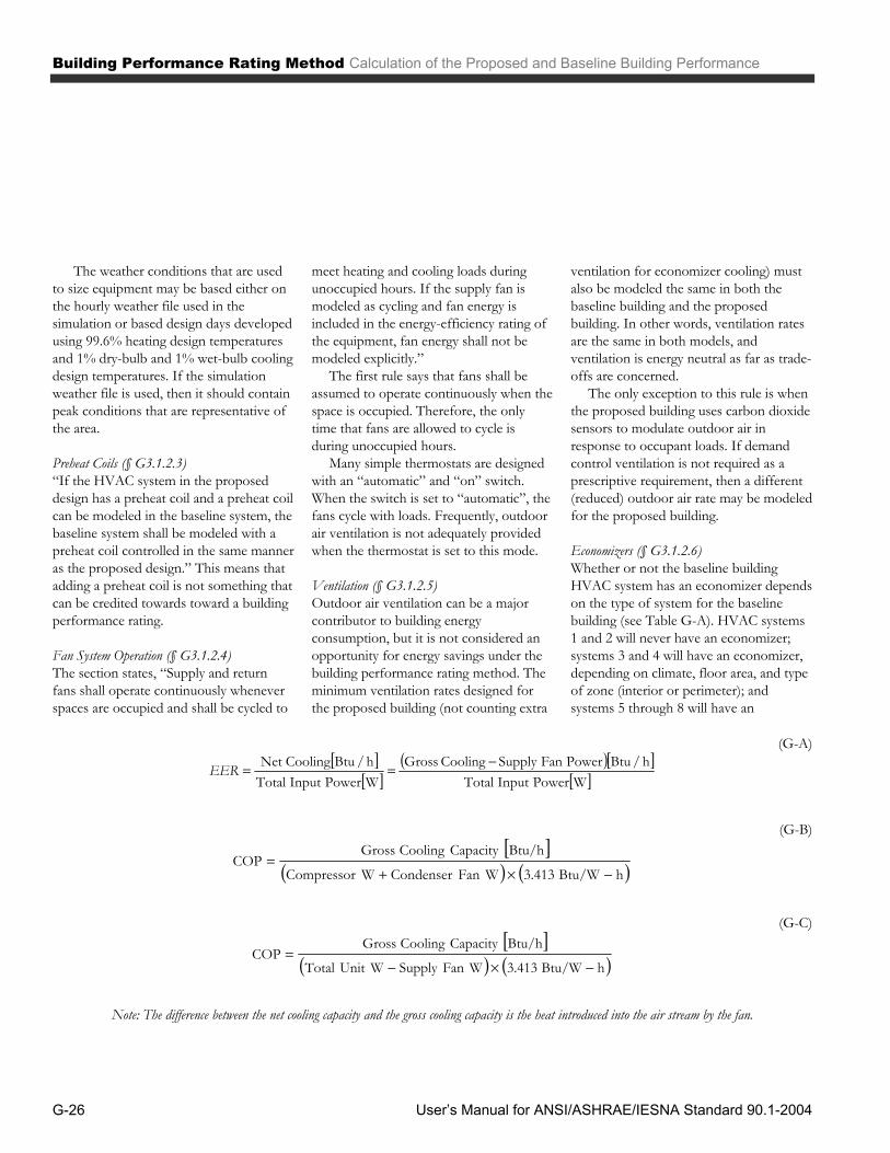
Building Performance Rating Method Calculation of the Proposed and Baseline Building Performance
User’s Manual for ANSI/ASHRAE/IESNA Standard 90.1-2004 G-26
The weather conditions that are used to size equipment may be based either on the hourly weather file used in the simulation or based design days developed using 99.6% heating design temperatures and 1% dry-bulb and 1% wet-bulb cooling design temperatures. If the simulation weather file is used, then it should contain peak conditions that are representative of the area.
Preheat Coils (§ G3.1.2.3) “If the HVAC system in the proposed design has a preheat coil and a preheat coil can be modeled in the baseline system, the baseline system shall be modeled with a preheat coil controlled in the same manner as the proposed design.” This means that adding a preheat coil is not something that can be credited towards toward a building performance rating.
Fan System Operation (§ G3.1.2.4) The section states, “Supply and return fans shall operate continuously whenever spaces are occupied and shall be cycled to
meet heating and cooling loads during unoccupied hours. If the supply fan is modeled as cycling and fan energy is included in the energy-efficiency rating of the equipment, fan energy shall not be modeled explicitly.”
The first rule says that fans shall be assumed to operate continuously when the space is occupied. Therefore, the only time that fans are allowed to cycle is during unoccupied hours.
Many simple thermostats are designed with an “automatic” and “on” switch. When the switch is set to “automatic”, the fans cycle with loads. Frequently, outdoor air ventilation is not adequately provided when the thermostat is set to this mode.
Ventilation (§ G3.1.2.5) Outdoor air ventilation can be a major contributor to building energy consumption, but it is not considered an opportunity for energy savings under the building performance rating method. The minimum ventilation rates designed for the proposed building (not counting extra
ventilation for economizer cooling) must also be modeled the same in both the baseline building and the proposed building. In other words, ventilation rates are the same in both models, and ventilation is energy neutral as far as trade-offs are concerned.
The only exception to this rule is when the proposed building uses carbon dioxide sensors to modulate outdoor air in response to occupant loads. If demand control ventilation is not required as a prescriptive requirement, then a different (reduced) outdoor air rate may be modeled for the proposed building.
Economizers (§ G3.1.2.6) Whether or not the baseline building HVAC system has an economizer depends on the type of system for the baseline building (see Table G-A). HVAC systems 1 and 2 will never have an economizer; systems 3 and 4 will have an economizer, depending on climate, floor area, and type of zone (interior or perimeter); and systems 5 through 8 will have an
(G-A)
WPowerInputTotalh/BtuPowerFanSupplyCoolingGross
WPowerInputTotalh/BtuCoolingNetEER
(G-B)
hBtu/W3.413WFanCondenserWCompressor
Btu/hCapacityCoolingGrossCOP
(G-C)
hBtu/W3.413WFanSupplyWUnitTotal
Btu/hCapacityCoolingGrossCOP
Note: The difference between the net cooling capacity and the gross cooling capacity is the heat introduced into the air stream by the fan.

Calculation of the Proposed and Baseline Building Performance Building Performance Rating Method
User’s Manual for ANSI/ASHRAE/IESNA Standard 90.1-2004 G-27
economizer based just on climate. More details on the systems for which economizers may be required follow. ▪ Systems 3 and 4 are single zone
packages with either gas or heat pump heating. Whether the baseline building system has an economizer depends on the area served by the system, whether the zone served is a perimeter or an interior zone, and climate. Table G3.1.2.6A gives the floor area served by the system, above which an economizer is needed. For the purposes of defining interior and perimeter zones, any thermal zone that has more than half of its floor area located more than 15 ft from an exterior wall is to be considered an interior zone, otherwise, it is a perimeter zone. ▪ Systems 5 through 8 are variable air
volume, multiple zone systems. For these the area served and the type of zone (interior or perimeter) is not relevant in determining if the baseline building HVAC system has an economizer. The only factor is climate (see Table G3.1.2.6B). The baseline building HVAC system shall not have an economizer for one or both of the following conditions:
(a) Systems that include gas phase air cleaning to meet the requirements of 6.1.2 of ANSI/ASHRAE Standard 62-1999;
(b) Where the use of outdoor air for cooling will affect supermarket open refrigerated casework.
Economizer High-Limit Shutoff (§ G3.1.2.7) When an economizer is required, it must have a high-limit shutoff switch that senses dry-bulb temperature and shuts off economizer operation (reduces outdoor air to the minimum required for ventilation) when the outdoor temperature exceeds the values shown in Table G3.1.2.6C. The specific high-limit shutoff temperature depends on the climate zone.
Example G-H—Economizer Requirements, North Carolina
Q Does the baseline building HVAC system for a two-story 40,000 ft² office building in Ashville, North Carolina require an economizer? The proposed building is served by a central VAV system with a hot water gas fired boiler.
A Using Table G3.1.1A, the baseline building HVAC system type is a packaged single zone air conditioner (HVAC System 3 – PSZ-AC). A separate system serves each of the thermal blocks modeled in the proposed building. Entering Table G3.1.2.6A with the above climate data, systems that serve perimeter zones are not required to have an economizer while interior system that serve 15,000 ft² or more are required to have an economizer. Example G-I—Economizer Requirements, San Francisco
Q If the building in the previous example were in San Francisco, California, would it be required to have an economizer?
A Consulting Table B-1, we find that San Francisco, California is classified as climate zone 3C. Referring to Table G3.1.2.6A with this knowledge, we see that the answer will depend on the floor area and type of zone served. If it is a perimeter zone and the floor area is greater than 25,000 ft², an economizer will be required. If it is an interior zone of 10,000 ft² or more, an economizer will be required.
.
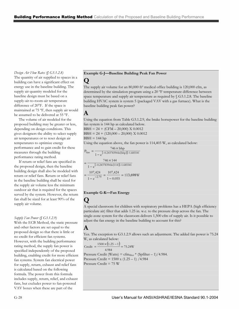
Building Performance Rating Method Calculation of the Proposed and Baseline Building Performance
User’s Manual for ANSI/ASHRAE/IESNA Standard 90.1-2004 G-28
Design Air Flow Rates (§ G3.1.2.8) The quantity of air supplied to spaces in a building can have a significant effect on energy use in the baseline building. The supply air quantity modeled for the baseline design must be based on a supply-air-to-room-air temperature difference of 20°F. If the space is maintained at 75 ºF, then supply air would be assumed to be delivered at 55 ºF.
The volume of air modeled for the proposed building may be greater or less, depending on design conditions. This gives designers the ability to select supply air temperatures or to reset design air temperatures to optimize energy performance and to gain credit for these measures through the building performance rating method.
If return or relief fans are specified in the proposed design, then the baseline building design shall also be modeled with return or relief fans. Return or relief fans in the baseline building shall be sized for the supply air volume less the minimum outdoor air that is required for the spaces served by the system. However, the return fan shall be sized for at least 90% of the supply air volume.
Supply Fan Power (§ G3.1.2.9) With the ECB Method, the static pressure and other factors are set equal to the proposed design so that there is little or no credit for efficient fan systems. However, with the building performance rating method, the supply fan power is specified independently of the proposed building, enabling credit for more efficient fan systems. System fan electrical power for supply, return, exhaust and relief fans is calculated based on the following formula. The power from this formula includes supply, return, relief, and exhaust fans, but excludes power to fan-powered VAV boxes when these are part of the
Example G-J—Baseline Building Peak Fan Power
Q The supply air volume for an 80,000 ft² medical office building is 120,000 cfm, as determined by the simulation program using a 20 ºF temperature difference between space temperature and supply air temperature as required by § G3.1.2.8. The baseline building HVAC system is system 5 (packaged VAV with a gas furnace). What is the baseline building peak fan power?
A Using the equation from Table G3.1.2.9, the brake horsepower for the baseline building fan system is 144 hp as calculated below. BBH = 24 + (CFM – 20,000) X 0.0012 BBH = 24 + (120,000 – 20,000) X 0.0012 BBH = 144 hp Using the equation above, the fan power is 114,403 W, as calculated below:
W10.0551
107,424
e1
107,424e1
144746e1
bhp746P
2.79
1.685541114ln0.2437839
1.685541bhpln0.2437839fan
698,13
Example G-K—Fan Energy
Q A special classroom for children with respiratory problems has a HEPA (high efficiency particulate air) filter that adds 1.25 in. w.c. to the pressure drop across the fan. The single-zone system for the classroom delivers 1,500 cfm of supply air. Is it possible to adjust the fan energy in the baseline building to account for this?
A Yes. The exception to G3.1.2.9 allows such an adjustment. The added fan power is 75.24 W, as calculated below:
75.24W4.984
11.251500Credit
Pressure Credit (Watts) = cfmfilter * (Spfilter – 1)/4.984. Pressure Credit = 1500 x (1.25 – 1) /4.984 Pressure Credit = 75 W
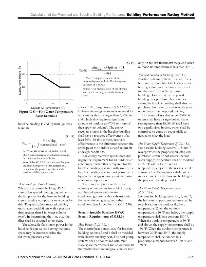
Calculation of the Proposed and Baseline Building Performance Building Performance Rating Method
User’s Manual for ANSI/ASHRAE/IESNA Standard 90.1-2004 G-29
baseline building HVAC system (systems 6 and 8).
(G-D)
1.6855bhpln0.2438fane1
bhp746P
Pfan = electric power to fan motor (watts). bhp = brake horsepower of baseline building fan motor as determined below NOTE: Table G3.1.2.9 has equations that give the brake horsepower of fan systems as a function of the peak design cfm and the baseline building system type.
Adjustments for Special Filtering. When the proposed building HVAC system has special filtering requirements, the fan power for the baseline building system is adjusted upwards to account for this. To qualify, the proposed building must have special filters with a pressure drop greater than 1 in. water column (w.c.). In determining the 1 in. w.c., the filter shall be assumed to be clean.
The allowable fan system power in the baseline design system serving the same space may be increased using the following pressure credit.
(G-E)
4.984
1SpfiltercfmCredit filter
CFMfilter = supply air volume of the proposed system with air filtration system in excess on 1 in. w. c. Spfilter = air pressure drop of the filtering system in in. of w. g. when the filters are clean.
Exhaust Air Energy Recovery (§ G3.1.2.10) Exhaust air energy recovery is required for fan systems that are larger than 5,000 cfm and which also require a significant amount of outdoor air (70% or more of the supply air volume). The energy recovery system in the baseline building shall have a recovery effectiveness of at least 50%. In this context, recovery effectiveness is the difference between the enthalpy of the outdoor air and return air at design conditions.
The energy recovery system does not negate the requirement for an outdoor air economizer, when this is required for the baseline building system. Furthermore, the baseline building system must permit air to bypass the energy recovery system during economizer operation.
There are exceptions to the heat-recovery requirements for mild climates, semiheated spaces with no air-conditioning, systems that exhaust toxic fumes or kitchen grease, and other conditions (See Exceptions to G3.1.2.10).
System-Specific Baseline HVAC System Requirements (§ G3.1.3)
Heat Pumps (§ G3.1.3.1) The electric heat pumps used for baseline building systems 2 and 4 shall be modeled with electric auxiliary heat. The heat pump systems shall be controlled with multi-stage space thermostats and an outdoor air thermostat wired to energize auxiliary heat
only on the last thermostat stage and when outdoor air temperature is less than 40 ºF.
Type and Number of Boilers (§ G3.1.3.2) Baseline building systems 1, 5, and 7 shall have one or more fossil fuel boiler as the heating source and the boiler plant shall use the same fuel as the proposed building. However, if the proposed building uses purchased hot water or steam, the baseline building shall also use purchased hot water or steam at the same utility rate as the proposed building.
Hot water plants that serve 15,000 ft² or less shall have a single boiler. Plants serving more than 15,000 ft² shall have two equally sized boilers, which shall be controlled to come on sequentially as needed to meet the load.
Hot Water Supply Temperature (§ G3.1.3.3) For baseline building systems 1, 5, and 7 (except when the proposed building uses purchased steam or hot water), the hot water supply temperature shall be modeled at 180 ºF with a 130 ºF return temperature, subject to the reset schedule shown below. Piping losses shall not be modeled in either the baseline building or the proposed building model.
Hot Water Supply Temperature Reset (§ G3.1.3.4) For baseline building systems 1, 5, and 7, the hot water supply temperature shall be reset based on the outdoor dry-bulb temperature. When the outdoor temperature is 20 ºF and below, the supply temperature shall be a constant 180 ºF. When the outdoor temperature is 50 ºF and above, the supply temperature shall be 150 ºF. When the outdoor temperature is between 20 ºF and 50 ºF, the supply temperature shall be ramped in a proportional manner between 180 ºF and 150 ºF.
180
150
0
0 20 40 60
Figure G-G—Hot Water Temperature
Reset Schedule
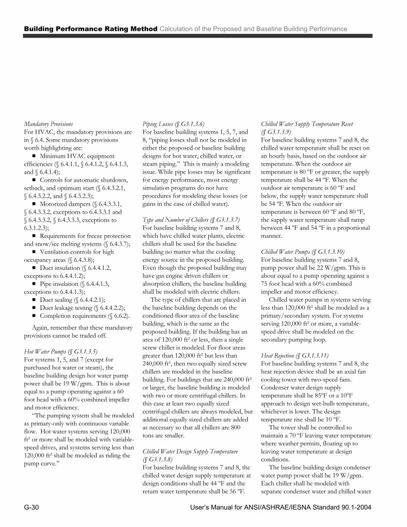
Building Performance Rating Method Calculation of the Proposed and Baseline Building Performance
User’s Manual for ANSI/ASHRAE/IESNA Standard 90.1-2004 G-30
Mandatory Provisions For HVAC, the mandatory provisions are in § 6.4. Some mandatory provisions worth highlighting are: ▪ Minimum HVAC equipment
efficiencies (§ 6.4.1.1, § 6.4.1.2, § 6.4.1.3, and § 6.4.1.4); ▪ Controls for automatic shutdown,
setback, and optimum start (§ 6.4.3.2.1, § 6.4.3.2.2, and § 6.4.3.2.3); ▪ Motorized dampers (§ 6.4.3.3.1,
§ 6.4.3.3.2, exceptions to 6.4.3.3.1 and § 6.4.3.3.2, § 6.4.3.3.3, exceptions to 6.3.1.2.3); ▪ Requirements for freeze protection
and snow/ice melting systems (§ 6.4.3.7); ▪ Ventilation controls for high
occupancy areas (§ 6.4.3.8); ▪ Duct insulation (§ 6.4.4.1.2,
exceptions to 6.4.4.1.2); ▪ Pipe insulation (§ 6.4.4.1.3,
exceptions to 6.4.4.1.3); ▪ Duct sealing (§ 6.4.4.2.1); ▪ Duct leakage testing (§ 6.4.4.2.2); ▪ Completion requirements (§ 6.6.2). Again, remember that these mandatory
provisions cannot be traded off.
Hot Water Pumps (§ G3.1.3.5) For systems 1, 5, and 7 (except for purchased hot water or steam), the baseline building design hot water pump power shall be 19 W/gpm. This is about equal to a pump operating against a 60 foot head with a 60% combined impeller and motor efficiency.
“The pumping system shall be modeled as primary-only with continuous variable flow. Hot water systems serving 120,000 ft² or more shall be modeled with variable-speed drives, and systems serving less than 120,000 ft² shall be modeled as riding the pump curve.”
Piping Losses (§ G3.1.3.6) For baseline building systems 1, 5, 7, and 8, “piping losses shall not be modeled in either the proposed or baseline building designs for hot water, chilled water, or steam piping.” This is mainly a modeling issue. While pipe losses may be significant for energy performance, most energy simulation programs do not have procedures for modeling these losses (or gains in the case of chilled water).
Type and Number of Chillers (§ G3.1.3.7) For baseline building systems 7 and 8, which have chilled water plants, electric chillers shall be used for the baseline building no matter what the cooling energy source in the proposed building. Even though the proposed building may have gas engine driven chillers or absorption chillers, the baseline building shall be modeled with electric chillers.
The type of chillers that are placed in the baseline building depends on the conditioned floor area of the baseline building, which is the same as the proposed building. If the building has an area of 120,000 ft² or less, then a single screw chiller is modeled. For floor areas greater than 120,000 ft² but less than 240,000 ft², then two equally sized screw chillers are modeled in the baseline building. For buildings that are 240,000 ft² or larger, the baseline building is modeled with two or more centrifugal chillers. In this case at least two equally sized centrifugal chillers are always modeled, but additional equally sized chillers are added as necessary so that all chillers are 800 tons are smaller.
Chilled Water Design Supply Temperature (§ G3.1.3.8) For baseline building systems 7 and 8, the chilled water design supply temperature at design conditions shall be 44 ºF and the return water temperature shall be 56 ºF.
Chilled Water Supply Temperature Reset (§ G3.1.3.9) For baseline building systems 7 and 8, the chilled water temperature shall be reset on an hourly basis, based on the outdoor air temperature. When the outdoor air temperature is 80 ºF or greater, the supply temperature shall be 44 ºF. When the outdoor air temperature is 60 ºF and below, the supply water temperature shall be 54 ºF. When the outdoor air temperature is between 60 ºF and 80 ºF, the supply water temperature shall ramp between 44 ºF and 54 ºF in a proportional manner.
Chilled Water Pumps (§ G3.1.3.10) For baseline building systems 7 and 8, pump power shall be 22 W/gpm. This is about equal to a pump operating against a 75 foot head with a 60% combined impeller and motor efficiency.
Chilled water pumps in systems serving less than 120,000 ft² shall be modeled as a primary/secondary system. For systems serving 120,000 ft² or more, a variable-speed drive shall be modeled on the secondary pumping loop.
Heat Rejection (§ G3.1.3.11) For baseline building systems 7 and 8, the heat rejection device shall be an axial fan cooling tower with two-speed fans. Condenser water design supply temperature shall be 85ºF or a 10ºF approach to design wet-bulb temperature, whichever is lower. The design temperature rise shall be 10 ºF.
The tower shall be controlled to maintain a 70 ºF leaving water temperature where weather permits, floating up to leaving water temperature at design conditions.
The baseline building design condenser water pump power shall be 19 W/gpm. Each chiller shall be modeled with separate condenser water and chilled water
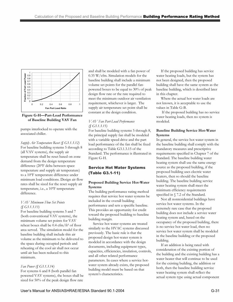
Calculation of the Proposed and Baseline Building Performance Building Performance Rating Method
User’s Manual for ANSI/ASHRAE/IESNA Standard 90.1-2004 G-31
pumps interlocked to operate with the associated chiller.
Supply Air Temperature Reset (§ G3.1.3.12) For baseline building systems 5 through 8 (all VAV systems), the supply air temperature shall be reset based on zone demand from the design temperature difference (20ºF delta between space temperature and supply air temperature) to a 10ºF temperature difference under minimum load conditions. Design air flow rates shall be sized for the reset supply air temperature, i.e., a 10ºF temperature difference.
VAV Minimum Flow Set Points (§ G3.1.3.13) For baseline building systems 5 and 7 (both conventional VAV systems), the minimum volume set points for VAV reheat boxes shall be 0.4 cfm/ft² of floor area served. The simulation model for the baseline building shall include this air volume as the minimum to be delivered to the space during occupied periods and reheating of the cool air shall not occur until air has been reduced to this minimum.
Fan Power (§ G3.1.3.14) For systems 6 and 8 (both parallel fan powered VAV systems), the boxes shall be sized for 50% of the peak design flow rate
and shall be modeled with a fan power of 0.35 W/cfm. Simulation models for the baseline building shall include a minimum volume set points for the parallel fan-powered boxes to be equal to 30% of peak design flow rate or the rate required to meet the minimum outdoor air ventilation requirement, whichever is larger. The supply air temperature set point shall be constant at the design condition.
VAV Fan Part-Load Performance (§ G3.1.3.15) For baseline building systems 5 through 8, the principal supply fan shall be modeled with a variable speed drive and the part load performance of the fan shall be fixed according to Table G3.1.3.15 of the Standard. The performance is illustrated in Figure G-H.
Service Hot Water Systems (Table G3.1-11)
Proposed Building Service Hot-Water Systems The building performance rating method requires that service hot water systems be included in the overall building performance and sets a specific baseline. This provides an opportunity for credit toward the proposed building to baseline building margin.
Service hot water systems are treated similarly to the HVAC systems discussed previously. The basic rule is that the proposed design hot-water system is modeled in accordance with the design documents, including equipment types, capacities, efficiencies, insulation, controls, and all other related performance parameters. In cases where a service hot-water system already exists, the proposed building model must be based on that system’s characteristics.
If the proposed building has service water heating loads, but the system has not been designed, then the proposed building shall have the same system as the baseline building, which is described later in this chapter.
Where the actual hot water loads are not known, it is acceptable to use the values in Table G-B.
If the proposed building has no service water heating loads, then no system is modeled.
Baseline Building Service Hot-Water Systems In general, the service hot water system in the baseline building shall comply with the mandatory measures and prescriptive requirements specified in Chapter 7 of the Standard. The baseline building water heating system shall use the same energy source as the proposed building, if the proposed building uses electric water heaters, then so should the baseline building. The baseline building service water heating system shall meet the minimum efficiency requirements specified in § 7.2 of the Standard.
Not all nonresidential buildings have service hot water systems. In the extremely rare case that the proposed building does not include a service water heating system and, based on the occupancy of the proposed building, there is no service hot water load, then no service hot water system shall be modeled in the baseline building or the proposed building.
If an addition is being rated with consideration of the existing portion of the building and the existing building has a water heater that will continue to be used for the existing building, the addition or both, then the baseline building service water heating system shall reflect the actual system type using actual component
00.10.20.30.40.50.60.70.80.9
1
0 0.2 0.4 0.6 0.8 1
Fan Part Load Ratio
Frac
tion
of F
ull L
oad
Pow
er
Figure G-H—Part-Load Performance
of Baseline Building VAV Fan

Building Performance Rating Method Calculation of the Proposed and Baseline Building Performance
User’s Manual for ANSI/ASHRAE/IESNA Standard 90.1-2004 G-32
capacities and efficiencies of the existing system.
In the case where the proposed building does not include a service water heating system, but based on the occupancy of the proposed building, the building has service water loads, then an electric resistance electric water heating system shall be used for both the baseline building and the proposed building that meets the minimum efficiency requirements of § 7.2. An identical system shall be used for both the proposed building and the baseline building so that there is no benefit or penalty in the building performance rating.
When the proposed building includes a single system for both space heating and service water heating, the baseline building
shall use separate systems meeting the minimum efficiency requirements applicable to each system individually.
When the prescriptive requirements of § 6.3.6.2 require that heat be recovered from air conditioning condensers, then the baseline building shall include condenser heat recovery, without consideration of the exceptions to 6.3.6.2. This requirement applies to 24-hour facilities like hotels that have a peak service water heating load of 1,000,000 Btu/h or more and the heat rejection system (cooling tower) has a capacity of 6,000,000 Btu/h or more. The heat recovery system shall have the capability to either preheat the service hot water to at least 85 ºF or to recover at least 60% of the peak heat rejection load at design conditions.
If the simulation program is not capable of modeling a condenser heat recovery system, then the proposed building shall be designed to meet the prescriptive requirements in accordance with § 6.5.6.2, and no heat-recovery system shall be included in either the proposed building or the baseline building.
Mandatory Provisions For service water heating, the mandatory provisions are described in § 7.4. Some mandatory provisions worth highlighting are: ▪ Minimum service water heating
equipment (§ 7.4.2, exception to 7.4.2); ▪ Pipe insulation (§ 7.4.3); ▪ Controls (§ 7.4.4); ▪ Pool covers (§ 7.4.5.2, exception to
Table G-B—Acceptable Occupant Densities, Receptacle Power Densities, and Service Hot Water Consumption1
Building Type
Occupancy Density2
Sq.Ft./Person (Btu/h . ft2)
Receptacle Power Density3
Watts/Sq.Ft. (Btu/h . ft2)
Service Hot Water Quantities4
Btu/h . Person
Assembly 50 (4.60) 0.25 (0.85) 215
Health/Institutional 200 (1.15) 1.00 (3.41) 135
Hotel/Motel 250 (0.92) 0.25 (0.85) 1,110
Light Manufacturing 750 (0.31) 0.20 (0.68) 225
Office 275 (0.84) 0.75 (2.56) 175
Parking Garage NA NA NA
Restaurant 100 (2.30) 0.10 (0.34) 390
Retail 300 (0.77) 0.25 (0.85) 135
School 75 (3.07) 0.50 (1.71) 215
Warehouse 15,000 (0.02) 0.10 (0.34) 225 1. The occupancy densities, receptacle power densities, and service hot water consumption values are from ASHRAE Standard 90.1-1989 and addenda. 2. Values are in square feet of conditioned floor area per person. Heat generation in Btu per person per hour is 230 sensible and 190 latent. Figures in parenthesis are equivalent Btu per
hour per square foot. 3. Values are in Watts per square foot of conditioned floor area. Figures in parenthesis are equivalent Btu per hour per square foot. These values are the minimum acceptable. If other
process loads are not input (such as for computers, cooking, refrigeration, etc.), it is recommended that receptacle power densities be increased until total process energy consumption is equivalent to 25% of the total.
4. Values are in Btu per person per hour.

Calculation of the Proposed and Baseline Building Performance Building Performance Rating Method
User’s Manual for ANSI/ASHRAE/IESNA Standard 90.1-2004 G-33
7.4.5.2); ▪ Heat traps (§ 7.4.6). Again, remember that these mandatory
provisions cannot be traded off.
Receptacle and other Loads (Table G3.1-12)
Receptacle and Process Loads Receptacle and process loads shall be estimated based on the building type of the proposed building or individual space types within the proposed building. These shall be included in the energy models for both the proposed building and the baseline building. These loads shall be the same for both the proposed building and the baseline building unless the rating authority had a procedure and method for crediting measures in the proposed building aimed at reducing receptacle energy.
Examples of receptacle loads include personal computers, copy machines, appliances in kitchens, printers, fax machines and any type of specialized equipment for specific building types, e.g. cooking equipment in restaurants, refrigerated casework in supermarkets and convenience stores, and specialized machinery in shops.
It is anticipated that most receptacle and process energy will be the same for both the proposed building and the baseline building. Rating authorities may, however, offer credit for the purchase of Energy STAR appliances and other equipment for which there is a performance rating.
Where the actual receptacle loads are not known, it is acceptable to use the values in Table G-B.
Systems that do not interact substantially with other energy systems, such as elevators or parking garage fans, should also be included, but may be estimated separately and added to the results of the energy simulation model.
Other Baseline Systems For motors, the baseline building must comply with the minimum efficiency requirements in § 10.4.1. Credit can be taken in the proposed building for motors with higher efficiencies. The building performance rating method does not allow credit for non-HVAC motors or for other miscellaneous energy-related equipment in a building, such as elevators, conveyors, autoclaves, etc. Where these systems contribute significant loads to the building, they should be modeled, but they must be identical in the proposed and budget runs.
For power distribution systems, the mandatory provisions are in § 8.4. For motors, the mandatory provisions are in § 10.4.1. Some mandatory provisions worth highlighting are: ▪ Feeders are allowed a maximum
voltage drop of 2% (§ 8.4.1.1); ▪ Completion requirements (§ 8.7.1,
§ 8.7.2); ▪ Minimum motor efficiency
requirements (§ 10.4.1). Again, remember that these are
mandatory requirements and cannot be traded off.
Modeling Limitations to the Simulation Program (Table G3.1-13) In general, all the energy systems of the proposed design must be included in the simulation model . However, in cases where the simulation program lacks modeling capabilities needed to fully model a component or system of the proposed design, the energy analyst may use a model that is thermodynamically equivalent. Making adjustments to lighting schedules to account for the benefits of daylighting is one example. Elevating the space temperature in the proposed building to account for temperature stratification in thermal displacement and under floor air distribution systems is another.
Good engineering judgment is required and to model the component or system using a thermodynamically similar model that is within the capabilities of the program being used. The energy analyst shall thoroughly understand the algorithms of the simulation program and the thermodynamic characteristics of the component being modeled. In many cases, this can be accomplished without compromising accuracy.
If a reasonable calculation of the proposed building performance rating cannot be made, then the best solution is to seek a different program that has the needed capabilities.

Building Performance Rating Method Case Study
User’s Manual for ANSI/ASHRAE/IESNA Standard 90.1-2004 G-34
To illustrate how to use the Appendix G Performance Rating Method, this case study reviews the step-by-step procedures followed for the same example building described in the ECB Case Study. These steps are:
1. Contact the rating authority. 2. Comply with the Mandatory
Requirements of § 5.4, § 6.4, § 7.4, § 8.4, § 9.4, and § 10.4.
3. Create the proposed design simulation model.
4. Create the baseline-building model.
5. Fine-tune the models. 6. Document performance rating.
Building Description The building in this case study is exactly the same as that used in the ECB Case Study. Please refer to that section in Chapter 11 of this Manual for details.
Step 1: Contact the Local Rating Authority Before using the Appendix G Performance Rating Method for a building, it’s important to confirm that the rating authority has approved the use of the method. Questions to ask of the authority include: ▪ Is the ANSI/ASHRAE/IESNA
90.1-2004 Appendix G Performance Rating Method accepted for showing a proposed design building having better energy performance than the baseline building? ▪ Have there been any
amendments? ▪ Are there any special limitations
or requirements on the use of the Appendix G method?
▪ Are there simulation programs that must be used? ▪ What climatic data are approved
for use in the energy simulations? ▪ What utility rate schedules are
approved for calculating energy costs?
Step 2: Comply With the Mandatory Provisions Both the baseline building design and the simulation used in the Appendix G method must comply with these requirements. See the technical chapters of this Manual (chapters 5, 6, 7, 8, 9, and 10) for details about the Standard’s Mandatory Requirements. These features must be included in the design documents.
Step 3: Create the Proposed Building Simulation Model The simulation model of the proposed design shall be consistent with the design documents, including proper accounting of fenestration and opaque envelope types and areas; interior lighting power and controls; HVAC system types, sizes, and controls; and service water heating systems and controls. All end-use load components within and associated with the building shall be modeled, including, but not limited to, exhaust fans, parking garage ventilation fans, snow-melt and freeze-protection equipment, facade lighting, swimming pool heaters and pumps, elevators and escalators, refrigeration, and cooking.
For this case study, the proposed building is the almost same as the proposed building in the ECB Case Study in Chapter 11 of this Manual, except with no manually operated interior shades or blinds.
Step 4: Create the Baseline Building Simulation Model The simulation model of the baseline building is created by modifying the building envelope, fenestrations, lighting, HVAC systems, and central heating/cooling plant of the proposed building. If a computer program is certified by the rating authority for the performance rating method, the program will automatically generate a baseline building model from the inputs for the proposed building model. If no such program is available, then you should use the procedure for creating the baseline building that is described in Appendix G of the Standard.
The details below illustrate how to manually create the sample baseline building model. To determine the characteristics of the baseline building, fill out a set of the Standard’s compliance forms, but replace the actual characteristics of the proposed building with the minimally compliant values specified in Appendix G. Where there is no guidance from the Appendix G about which values should be used, then model the baseline building with values identical to the proposed building. For example, in this case study, there is no requirement for the lighting power density in dwelling units (see exception (b) to § 9.1); therefore, the lighting power in the living spaces will be identical in both models.
Space-Conditioning Categories The baseline building and the proposed building have the same space use classification.
Case Study
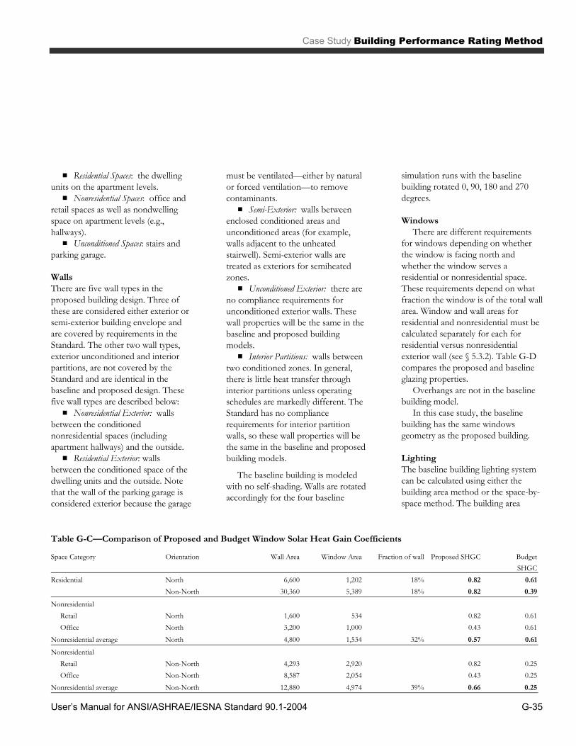
Case Study Building Performance Rating Method
User’s Manual for ANSI/ASHRAE/IESNA Standard 90.1-2004 G-35
▪ Residential Spaces: the dwelling units on the apartment levels. ▪ Nonresidential Spaces: office and
retail spaces as well as nondwelling space on apartment levels (e.g., hallways). ▪ Unconditioned Spaces: stairs and
parking garage.
Walls There are five wall types in the proposed building design. Three of these are considered either exterior or semi-exterior building envelope and are covered by requirements in the Standard. The other two wall types, exterior unconditioned and interior partitions, are not covered by the Standard and are identical in the baseline and proposed design. These five wall types are described below: ▪ Nonresidential Exterior: walls
between the conditioned nonresidential spaces (including apartment hallways) and the outside. ▪ Residential Exterior: walls
between the conditioned space of the dwelling units and the outside. Note that the wall of the parking garage is considered exterior because the garage
must be ventilated—either by natural or forced ventilation—to remove contaminants. ▪ Semi-Exterior: walls between
enclosed conditioned areas and unconditioned areas (for example, walls adjacent to the unheated stairwell). Semi-exterior walls are treated as exteriors for semiheated zones. ▪ Unconditioned Exterior: there are
no compliance requirements for unconditioned exterior walls. These wall properties will be the same in the baseline and proposed building models. ▪ Interior Partitions: walls between
two conditioned zones. In general, there is little heat transfer through interior partitions unless operating schedules are markedly different. The Standard has no compliance requirements for interior partition walls, so these wall properties will be the same in the baseline and proposed building models.
The baseline building is modeled
with no self-shading. Walls are rotated accordingly for the four baseline
simulation runs with the baseline building rotated 0, 90, 180 and 270 degrees.
Windows There are different requirements
for windows depending on whether the window is facing north and whether the window serves a residential or nonresidential space. These requirements depend on what fraction the window is of the total wall area. Window and wall areas for residential and nonresidential must be calculated separately for each for residential versus nonresidential exterior wall (see § 5.3.2). Table G-D compares the proposed and baseline glazing properties. Overhangs are not in the baseline building model. In this case study, the baseline building has the same windows geometry as the proposed building.
Lighting The baseline building lighting system can be calculated using either the building area method or the space-by-space method. The building area
Table G-C—Comparison of Proposed and Budget Window Solar Heat Gain Coefficients
Space Category Orientation Wall Area Window Area Fraction of wall Proposed SHGC BudgetSHGC
Residential North 6,600 1,202 18% 0.82 0.61 Non-North 30,360 5,389 18% 0.82 0.39Nonresidential Retail North 1,600 534 0.82 0.61 Office North 3,200 1,000 0.43 0.61Nonresidential average North 4,800 1,534 32% 0.57 0.61Nonresidential Retail Non-North 4,293 2,920 0.82 0.25 Office Non-North 8,587 2,054 0.43 0.25Nonresidential average Non-North 12,880 4,974 39% 0.66 0.25

Building Performance Rating Method Case Study
User’s Manual for ANSI/ASHRAE/IESNA Standard 90.1-2004 G-36
method requires fewer inputs (see Table 9.3.1.1 of the Standard). For simplicity’s sake, this is the method used in this case study. If the building area method is used, it must be used throughout the whole project.
Table G-D compares the proposed and baseline lighting power densities for the different spaces.
Even though the parking garage is considered unconditioned and unenclosed, it is still an interior space for lighting purposes and is available for lighting power trade-offs with the rest of the building. Note that the multi-family hallway is considered separately from the apartments. The hallway is considered a nonresidential space with limitations on lighting power. The dwelling units inside the building are exempt from lighting power density requirements and thus the proposed design wattage and baseline lighting wattage are identical.
The baseline building does not have daylight dimming controls for the office spaces.
Mechanical
Defining the Mechanical System The type of mechanical system used in the baseline building is based upon the following evaluation of the systems in
the proposed building. To define the air-handling systems for the baseline building, answer the following four questions and consult Tables G3.1.1A and G3.1.1B. ▪ Is the building for residential or
nonresidential use? ▪ How many floors does the
building have? ▪ What is the total conditioned
floor area of the building? ▪ Is the heating source fossil fuel,
fossil/electric hybrid, purchased heat, or electric and other?
In the proposed building, there are
four stories of residential area and four stories of nonresidential area, both with conditioned floor area more than 20,000 ft². The nonresidential area has a total floor area of 54,000 ft², which is less than 75,000 ft². The heating source is a natural gas boiler. Therefore, system 1 – PTAC (Packaged Terminal Air-Conditioner) is selected to serve each dwelling unit in the residential area; while system 5 - Packaged VAV (with VSD fan) with Hot Water Reheat is selected to serve the office and retail areas. The parking garage is ventilated only and is served by the same system defined in the proposed building.
Economizer Although the proposed building has an air economizer for systems serving the office spaces, the Dallas climate (zone 3A) does not require an economizer for the baseline building (see Tables G3.1.2.6A and G3.1.2.6B).
Fans The fans in the baseline building’s HVAC systems have rated electric power based on Table G3.1.2.9 and formula defined in G3.1.2.9. The proposed building is allowed to get credit for lower fan energy use.
Exhaust Air Energy Recovery No exhaust air energy recovery is used in the baseline building as no HVAC systems require more than 70% of outdoor air.
Hot Water Pumps The baseline building has primary only hot water loop with continuous variable flow by constant speed pump consuming power of 19 W/gpm. The hot water deltaT is set to 50°F (with supply of 180°F and return of 130°F).
Controls All systems in the building have setback thermostats. The temperature schedules reflect that they are used to turn off commercial fan systems during unoccupied hours and to set back the residential temperatures at night. Since the office and retail systems have airflow rates in excess of 10,000 cfm, the baseline building model of these HVAC systems includes optimal start control. The minimum setpoint of the VAV boxes for the office and retail systems are set to 0.4 cfm/ft². The office and retail
Table G-D—Comparison of Proposed and Budget Lighting Power
Proposed Budget
Space Description Area Watts LPD Watts LPD
Parking 16,000 4,000 0.25 4,800 0.30 Retail 11,000 15,180 1.38 20,900 1.90 Office 27,000 31,320 1.16 35,100 1.30 Apartment units 43,600 71,940 1.65 71,940 1.65 Multi-family hallway 5,600 4,480 0.80 5,600 1.00 Totals 103,200 126,920 1.23 138,340 1.34

Case Study Building Performance Rating Method
User’s Manual for ANSI/ASHRAE/IESNA Standard 90.1-2004 G-37
systems have supply air temperature reset by warmest zones.
Cooling and Heating Equipment Sizing The baseline building HVAC systems are oversized 15% for cooling and 25% for heating. There is no chiller in the baseline building. The boiler plant is serving a conditioned floor area of more than 15,000 ft², therefore two equally sized boilers each with rated heating capacity of 750,000 Btu/h are used.
Cooling and Heating Equipment Efficiency The direct expansion cooling equipment for the baseline building has EER set to Table 6.2.1A for the office and retail systems, and to Table 6.2.1D for the residential systems. The EER is adjusted in the simulations to separately calculate the fan energy use. The boiler has a thermal efficiency of 75%.
Sizing Calculations The baseline building simulation does sizing calculations for each of the four orientations when the building is rotated.
Other Uses When using the performance rating method, all of the energy consumption in the building must be accounted for. This may introduce components that were not included in the ECB analysis.
Defining the Elevator System The elevator system used in the baseline building is the same as that of the proposed building.
Defining the Kitchen Cooking System The kitchen cooking system used in the baseline building is the same as that of the proposed building.
Defining the Kitchen Refrigeration System The kitchen refrigeration system used in the baseline building is the same as that of the proposed building.
Step 5: Fine-Tune the Models After both models have been run, the results are analyzed to check for errors and to verify performance. In some cases, unmet load warnings will indicate the number of hours that the system or plant was unable to meet the loads placed on them. This is commonly found in morning start-up situations where the pick-up loads cannot be met in a single hour.
If the number of hours that loads are unmet by either the systems or plant of either the baseline or the proposed model exceeds 300 hours of the 8760 hours simulated, or differs by more than 50 hours between the two models, these simulation results will not be accepted as valid. The best way to deal with this problem is to adjust the sizing of either the baseline or the proposed HVAC systems. As shown on the sample Performance Rating report, there are no load unmet hours for both models for this case study.
The baseline building is simulated four times with the building rotated 0, 90, 180 and 270 degrees. The baseline energy performance is the average of the four simulation results.
Both the proposed and the baseline building simulations are using the Texas utility rates from Table G-H Commercial Sector Average Energy Costs by State.
Step 6: Document Performance Rating The two-page Performance Rating report summarizes the finding that the proposed Dallas building would have lower energy costs than a Standard 90.1-2004 baseline building. A written description of those energy features that either exceed the minimal requirements or that are less than the requirements must be documented. The performance rating must be based on the latest proposed building design. If there are any changes in the proposed building, both the proposed building and the baseline building must be updated and re-run.
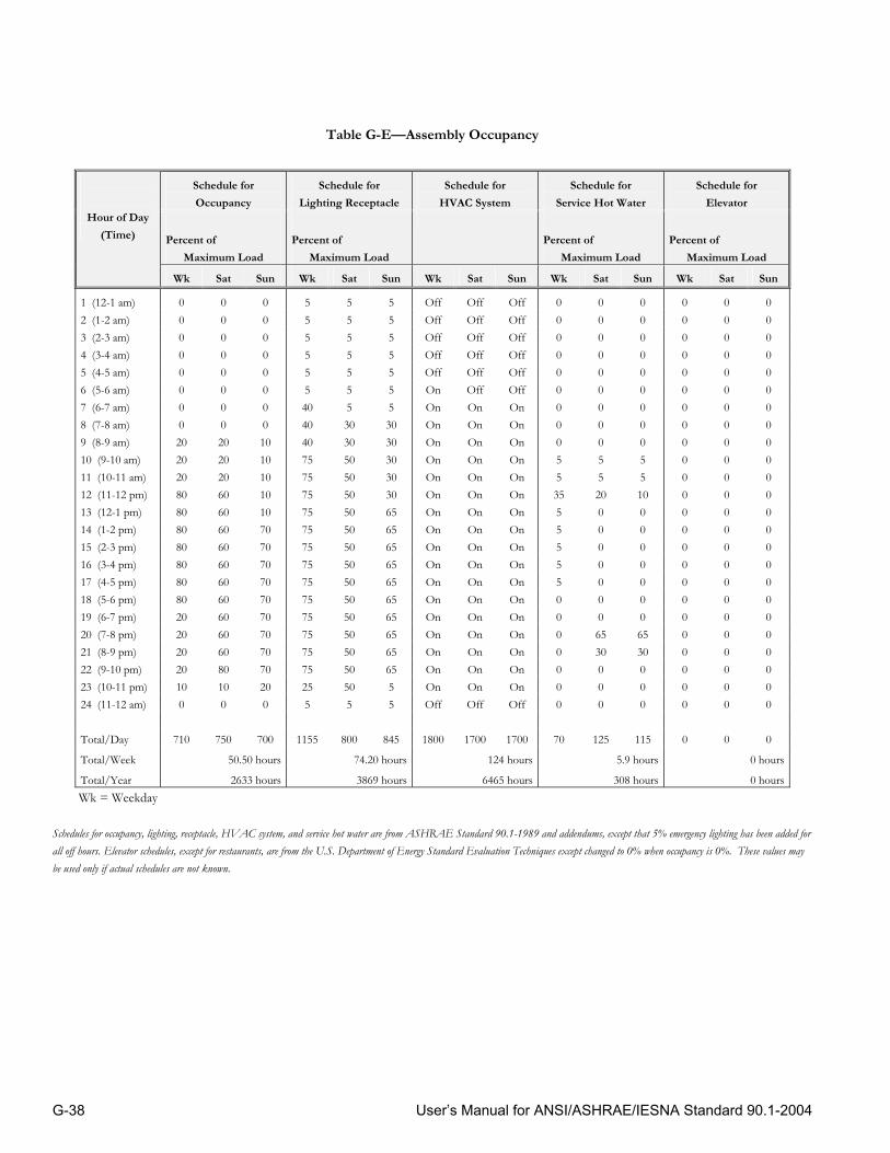
User’s Manual for ANSI/ASHRAE/IESNA Standard 90.1-2004 G-38
Table G-E—Assembly Occupancy
Schedule for Occupancy
Schedule for Lighting Receptacle
Schedule for HVAC System
Schedule for Service Hot Water
Schedule for Elevator
Percent of Maximum Load
Percent of Maximum Load
Percent of
Maximum Load Percent of
Maximum Load
Hour of Day (Time)
Wk Sat Sun Wk Sat Sun Wk Sat Sun Wk Sat Sun Wk Sat Sun
1 (12-1 am) 0 0 0 5 5 5 Off Off Off 0 0 0 0 0 0 2 (1-2 am) 0 0 0 5 5 5 Off Off Off 0 0 0 0 0 0 3 (2-3 am) 0 0 0 5 5 5 Off Off Off 0 0 0 0 0 0 4 (3-4 am) 0 0 0 5 5 5 Off Off Off 0 0 0 0 0 0 5 (4-5 am) 0 0 0 5 5 5 Off Off Off 0 0 0 0 0 0 6 (5-6 am) 0 0 0 5 5 5 On Off Off 0 0 0 0 0 0 7 (6-7 am) 0 0 0 40 5 5 On On On 0 0 0 0 0 0 8 (7-8 am) 0 0 0 40 30 30 On On On 0 0 0 0 0 0 9 (8-9 am) 20 20 10 40 30 30 On On On 0 0 0 0 0 0 10 (9-10 am) 20 20 10 75 50 30 On On On 5 5 5 0 0 0 11 (10-11 am) 20 20 10 75 50 30 On On On 5 5 5 0 0 0 12 (11-12 pm) 80 60 10 75 50 30 On On On 35 20 10 0 0 0 13 (12-1 pm) 80 60 10 75 50 65 On On On 5 0 0 0 0 0 14 (1-2 pm) 80 60 70 75 50 65 On On On 5 0 0 0 0 0 15 (2-3 pm) 80 60 70 75 50 65 On On On 5 0 0 0 0 0 16 (3-4 pm) 80 60 70 75 50 65 On On On 5 0 0 0 0 0 17 (4-5 pm) 80 60 70 75 50 65 On On On 5 0 0 0 0 0 18 (5-6 pm) 80 60 70 75 50 65 On On On 0 0 0 0 0 0 19 (6-7 pm) 20 60 70 75 50 65 On On On 0 0 0 0 0 0 20 (7-8 pm) 20 60 70 75 50 65 On On On 0 65 65 0 0 0 21 (8-9 pm) 20 60 70 75 50 65 On On On 0 30 30 0 0 0 22 (9-10 pm) 20 80 70 75 50 65 On On On 0 0 0 0 0 0 23 (10-11 pm) 10 10 20 25 50 5 On On On 0 0 0 0 0 0 24 (11-12 am) 0 0 0 5 5 5 Off Off Off 0 0 0 0 0 0 Total/Day 710 750 700 1155 800 845 1800 1700 1700 70 125 115 0 0 0
Total/Week 50.50 hours 74.20 hours 124 hours 5.9 hours 0 hours
Total/Year 2633 hours 3869 hours 6465 hours 308 hours 0 hoursWk = Weekday
Schedules for occupancy, lighting, receptacle, HVAC system, and service hot water are from ASHRAE Standard 90.1-1989 and addendums, except that 5% emergency lighting has been added for all off hours. Elevator schedules, except for restaurants, are from the U.S. Department of Energy Standard Evaluation Techniques except changed to 0% when occupancy is 0%. These values may be used only if actual schedules are not known.

User’s Manual for ANSI/ASHRAE/IESNA Standard 90.1-2004 G-39
Table G-F—Health Occupancy
Schedule for Occupancy
Schedule for Lighting Receptacle
Schedule for HVAC System
Schedule for Service Hot Water
Schedule for Elevator
Percent of Maximum Load
Percent of Maximum Load
Percent of
Maximum Load Percent of
Maximum Load
Hour of Day (Time)
Wk Sat Sun Wk Sat Sun Wk Sat Sun Wk Sat Sun Wk Sat Sun
1 (12-1 am) 0 0 0 10 10 5 On On On 1 1 1 0 0 0 2 (1-2 am) 0 0 0 10 10 5 On On On 1 1 1 0 0 0 3 (2-3 am) 0 0 0 10 10 5 On On On 1 1 1 0 0 0 4 (3-4 am) 0 0 0 10 10 5 On On On 1 1 1 0 0 0 5 (4-5 am) 0 0 0 10 10 5 On On On 1 1 1 0 0 0 6 (5-6 am) 0 0 0 10 10 5 On On On 1 1 1 0 0 0 7 (6-7 am) 0 0 0 10 10 5 On On On 1 1 1 0 0 0 8 (7-8 am) 10 10 0 50 20 5 On On On 17 1 1 2 2 0 9 (8-9 am) 50 30 5 90 40 10 On On On 58 20 1 75 46 2 10 (9-10 am) 80 40 5 90 40 10 On On On 66 28 1 100 70 2 11 (10-11 am) 80 40 5 90 40 10 On On On 78 30 1 100 70 2 12 (11-12 pm) 80 40 5 90 40 10 On On On 82 30 1 100 70 2 13 (12-1 pm) 80 40 5 90 40 10 On On On 71 24 1 75 51 2 14 (1-2 pm) 80 40 5 90 40 10 On On On 82 24 1 100 51 2 15 (2-3 pm) 80 40 5 90 40 10 On On On 78 23 1 100 51 2 16 (3-4 pm) 80 40 5 90 40 10 On On On 74 23 1 100 51 2 17 (4-5 pm) 80 40 0 30 40 5 On On On 63 23 1 100 51 0 18 (5-6 pm) 50 10 0 30 40 5 On On On 41 10 1 100 25 0 19 (6-7 pm) 30 10 0 30 10 5 On On On 18 1 1 52 2 0 20 (7-8 pm) 30 0 0 30 10 5 On On On 18 1 1 52 0 0 21 (8-9 pm) 20 0 0 30 10 5 On On On 18 1 1 52 0 0 22 (9-10 pm) 20 0 0 30 10 5 On On On 10 1 1 28 0 0 23 (10-11 pm) 0 0 0 30 10 5 On On On 1 1 1 0 0 0 24 (11-12 am) 0 0 0 10 10 5 On On On 1 1 1 0 0 0 Total/Day 850 380 40 1060 550 160 2400 2400 2400 783 249 24 1136 540 16
Total/Week 46.70 hours 60.10 hours 168 hours 41.88 hours 62.36 hours
Total/Year 2435 hours 3134 hours 8760 hours 2148 hours 3251 hoursWk = Weekday
Schedules for occupancy, lighting, receptacle, HVAC system, and service hot water are from ASHRAE Standard 90.1-1989 and addendums, except that 5% emergency lighting has been added for all off hours. Elevator schedules, except for restaurants, are from the U.S. Department of Energy Standard Evaluation Techniques except changed to 0% when occupancy is 0%. These values may be used only if actual schedules are not known.
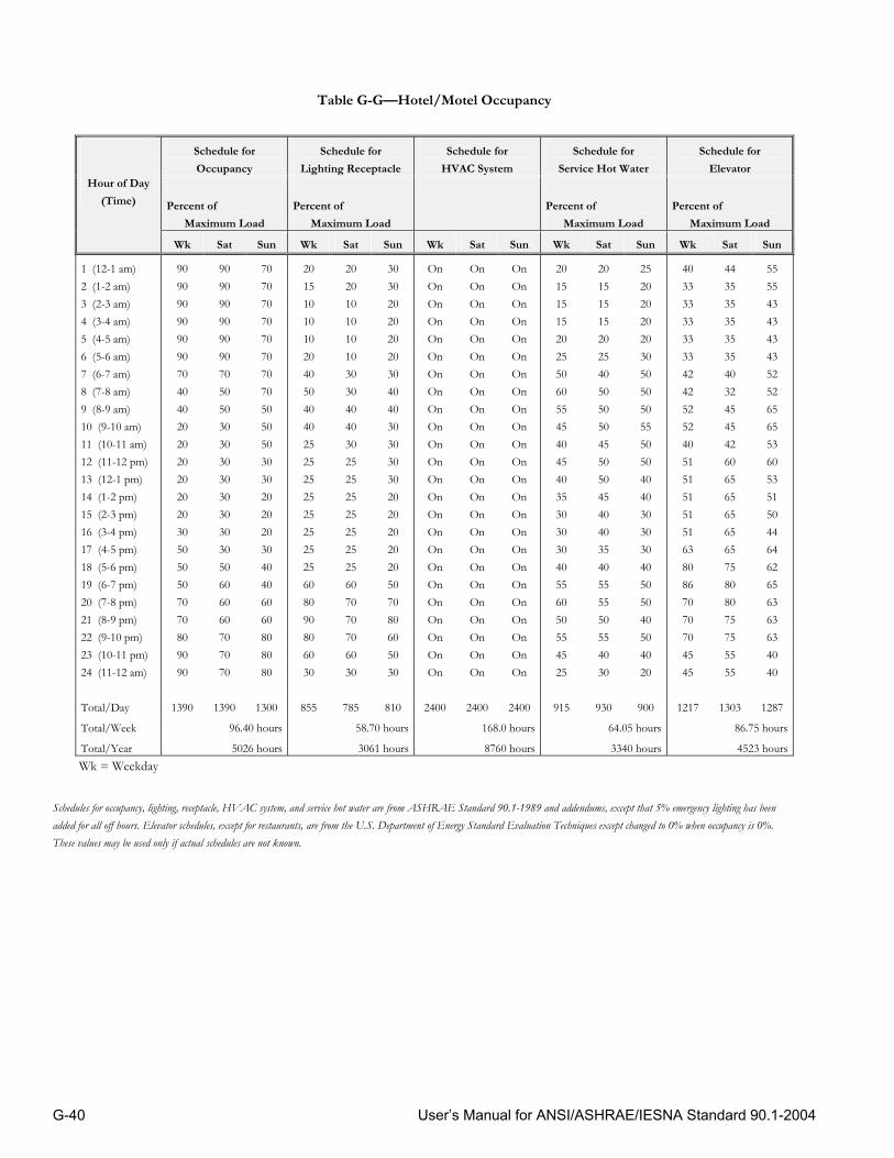
User’s Manual for ANSI/ASHRAE/IESNA Standard 90.1-2004 G-40
Table G-G—Hotel/Motel Occupancy
Schedule for Occupancy
Schedule for Lighting Receptacle
Schedule for HVAC System
Schedule for Service Hot Water
Schedule for Elevator
Percent of Maximum Load
Percent of Maximum Load
Percent of
Maximum Load Percent of
Maximum Load
Hour of Day (Time)
Wk Sat Sun Wk Sat Sun Wk Sat Sun Wk Sat Sun Wk Sat Sun
1 (12-1 am) 90 90 70 20 20 30 On On On 20 20 25 40 44 55 2 (1-2 am) 90 90 70 15 20 30 On On On 15 15 20 33 35 55 3 (2-3 am) 90 90 70 10 10 20 On On On 15 15 20 33 35 43 4 (3-4 am) 90 90 70 10 10 20 On On On 15 15 20 33 35 43 5 (4-5 am) 90 90 70 10 10 20 On On On 20 20 20 33 35 43 6 (5-6 am) 90 90 70 20 10 20 On On On 25 25 30 33 35 43 7 (6-7 am) 70 70 70 40 30 30 On On On 50 40 50 42 40 52 8 (7-8 am) 40 50 70 50 30 40 On On On 60 50 50 42 32 52 9 (8-9 am) 40 50 50 40 40 40 On On On 55 50 50 52 45 65 10 (9-10 am) 20 30 50 40 40 30 On On On 45 50 55 52 45 65 11 (10-11 am) 20 30 50 25 30 30 On On On 40 45 50 40 42 53 12 (11-12 pm) 20 30 30 25 25 30 On On On 45 50 50 51 60 60 13 (12-1 pm) 20 30 30 25 25 30 On On On 40 50 40 51 65 53 14 (1-2 pm) 20 30 20 25 25 20 On On On 35 45 40 51 65 51 15 (2-3 pm) 20 30 20 25 25 20 On On On 30 40 30 51 65 50 16 (3-4 pm) 30 30 20 25 25 20 On On On 30 40 30 51 65 44 17 (4-5 pm) 50 30 30 25 25 20 On On On 30 35 30 63 65 64 18 (5-6 pm) 50 50 40 25 25 20 On On On 40 40 40 80 75 62 19 (6-7 pm) 50 60 40 60 60 50 On On On 55 55 50 86 80 65 20 (7-8 pm) 70 60 60 80 70 70 On On On 60 55 50 70 80 63 21 (8-9 pm) 70 60 60 90 70 80 On On On 50 50 40 70 75 63 22 (9-10 pm) 80 70 80 80 70 60 On On On 55 55 50 70 75 63 23 (10-11 pm) 90 70 80 60 60 50 On On On 45 40 40 45 55 40 24 (11-12 am) 90 70 80 30 30 30 On On On 25 30 20 45 55 40 Total/Day 1390 1390 1300 855 785 810 2400 2400 2400 915 930 900 1217 1303 1287
Total/Week 96.40 hours 58.70 hours 168.0 hours 64.05 hours 86.75 hours
Total/Year 5026 hours 3061 hours 8760 hours 3340 hours 4523 hoursWk = Weekday
Schedules for occupancy, lighting, receptacle, HVAC system, and service hot water are from ASHRAE Standard 90.1-1989 and addendums, except that 5% emergency lighting has been added for all off hours. Elevator schedules, except for restaurants, are from the U.S. Department of Energy Standard Evaluation Techniques except changed to 0% when occupancy is 0%. These values may be used only if actual schedules are not known.

User’s Manual for ANSI/ASHRAE/IESNA Standard 90.1-2004 G-41
Table G-H—Light Manufacturing Occupancy
Schedule for Occupancy
Schedule for Lighting Receptacle
Schedule for HVAC System
Schedule for Service Hot Water
Schedule for Elevator
Percent of Maximum Load
Percent of Maximum Load
Percent of
Maximum Load Percent of
Maximum Load
Hour of Day (Time)
Wk Sat Sun Wk Sat Sun Wk Sat Sun Wk Sat Sun Wk Sat Sun
1 (12-1 am) 0 0 0 5 5 5 Off Off Off 5 5 4 0 0 0 2 (1-2 am) 0 0 0 5 5 5 Off Off Off 5 5 4 0 0 0 3 (2-3 am) 0 0 0 5 5 5 Off Off Off 5 5 4 0 0 0 4 (3-4 am) 0 0 0 5 5 5 Off Off Off 5 5 4 0 0 0 5 (4-5 am) 0 0 0 5 5 5 Off Off Off 5 5 4 0 0 0 6 (5-6 am) 0 0 0 10 5 5 Off Off Off 8 8 7 0 0 0 7 (6-7 am) 10 10 5 10 10 5 On On Off 7 7 4 0 0 0 8 (7-8 am) 20 10 5 30 10 5 On On Off 19 11 4 35 16 0 9 (8-9 am) 95 30 5 90 30 5 On On Off 35 15 4 69 14 0 10 (9-10 am) 95 30 5 90 30 5 On On Off 38 21 4 43 21 0 11 (10-11 am) 95 30 5 90 30 5 On On Off 39 19 4 37 18 0 12 (11-12 pm) 95 30 5 90 30 5 On On Off 47 23 6 43 25 0 13 (12-1 pm) 50 10 5 80 15 5 On On Off 57 20 6 58 21 0 14 (1-2 pm) 95 10 5 90 15 5 On On Off 54 19 9 48 13 0 15 (2-3 pm) 95 10 5 90 15 5 On On Off 34 15 6 37 8 0 16 (3-4 pm) 95 10 5 90 15 5 On On Off 33 12 4 37 4 0 17 (4-5 pm) 95 10 5 90 15 5 On On Off 44 14 4 46 5 0 18 (5-6 pm) 30 5 5 50 5 5 On On Off 26 7 4 62 6 0 19 (6-7 pm) 10 5 0 30 5 5 On Off Off 21 7 4 20 0 0 20 (7-8 pm) 10 0 0 30 5 5 On Off Off 15 7 4 12 0 0 21 (8-9 pm) 10 0 0 20 5 5 On Off Off 17 7 4 4 0 0 22 (9-10 pm) 10 0 0 20 5 5 On Off Off 8 9 7 4 0 0 23 (10-11 pm) 5 0 0 10 5 5 Off Off Off 5 5 4 0 0 0 24 (11-12 am) 5 0 0 5 5 5 Off Off Off 5 5 4 0 0 0 Total/Day 920 200 60 1040 280 120 1600 1200 0 537 256 113 555 151 0
Total/Week 48.60 hours 56.00 hours 92.00 hours 30.54 hours 29.26 hours
Total/Year 2534 hours 2920 hours 4797 hours 1592 hours 1526 hoursWk = Weekday
Schedules for occupancy, lighting, receptacle, HVAC system, and service hot water are from ASHRAE Standard 90.1-1989 and addendums, except that 5% emergency lighting has been added for all off hours. Elevator schedules, except for restaurants, are from the U.S. Department of Energy Standard Evaluation Techniques except changed to 0% when occupancy is 0%. These values may be used only if actual schedules are not known.

User’s Manual for ANSI/ASHRAE/IESNA Standard 90.1-2004 G-42
Table G-I—Office Occupancy
Schedule for Occupancy
Schedule for Lighting Receptacle
Schedule for HVAC System
Schedule for Service Hot Water
Schedule for Elevator
Percent of Maximum Load
Percent of Maximum Load
Percent of
Maximum Load Percent of
Maximum Load
Hour of Day (Time)
Wk Sat Sun Wk Sat Sun Wk Sat Sun Wk Sat Sun Wk Sat Sun
1 (12-1 am) 0 0 0 5 5 5 Off Off Off 5 5 4 0 0 0 2 (1-2 am) 0 0 0 5 5 5 Off Off Off 5 5 4 0 0 0 3 (2-3 am) 0 0 0 5 5 5 Off Off Off 5 5 4 0 0 0 4 (3-4 am) 0 0 0 5 5 5 Off Off Off 5 5 4 0 0 0 5 (4-5 am) 0 0 0 5 5 5 Off Off Off 5 5 4 0 0 0 6 (5-6 am) 0 0 0 10 5 5 Off Off Off 8 8 7 0 0 0 7 (6-7 am) 10 10 5 10 10 5 On On Off 7 7 4 0 0 0 8 (7-8 am) 20 10 5 30 10 5 On On Off 19 11 4 35 16 0 9 (8-9 am) 95 30 5 90 30 5 On On Off 35 15 4 69 14 0 10 (9-10 am) 95 30 5 90 30 5 On On Off 38 21 4 43 21 0 11 (10-11 am) 95 30 5 90 30 5 On On Off 39 19 4 37 18 0 12 (11-12 pm) 95 30 5 90 30 5 On On Off 47 23 6 43 25 0 13 (12-1 pm) 50 10 5 80 15 5 On On Off 57 20 6 58 21 0 14 (1-2 pm) 95 10 5 90 15 5 On On Off 54 19 9 48 13 0 15 (2-3 pm) 95 10 5 90 15 5 On On Off 34 15 6 37 8 0 16 (3-4 pm) 95 10 5 90 15 5 On On Off 33 12 4 37 4 0 17 (4-5 pm) 95 10 5 90 15 5 On On Off 44 14 4 46 5 0 18 (5-6 pm) 30 5 5 50 5 5 On On Off 26 7 4 62 6 0 19 (6-7 pm) 10 5 0 30 5 5 On Off Off 21 7 4 20 0 0 20 (7-8 pm) 10 0 0 30 5 5 On Off Off 15 7 4 12 0 0 21 (8-9 pm) 10 0 0 20 5 5 On Off Off 17 7 4 4 0 0 22 (9-10 pm) 10 0 0 20 5 5 On Off Off 8 9 7 4 0 0 23 (10-11 pm) 5 0 0 10 5 5 Off Off Off 5 5 4 0 0 0 24 (11-12 am) 5 0 0 5 5 5 Off Off Off 5 5 4 0 0 0 Total/Day 920 200 60 1040 280 120 1600 1200 0 537 256 113 555 151 0
Total/Week 48.60 hours 56.00 hours 92.00 hours 30.54 hours 29.26 hours
Total/Year 2534 hours 2920 hours 4797 hours 1592 hours 1526 hoursWk = Weekday
Schedules for occupancy, lighting, receptacle, HVAC system, and service hot water are from ASHRAE Standard 90.1-1989 and addendums, except that 5% emergency lighting has been added for all off hours. Elevator schedules, except for restaurants, are from the U.S. Department of Energy Standard Evaluation Techniques except changed to 0% when occupancy is 0%. These values may be used only if actual schedules are not known.

User’s Manual for ANSI/ASHRAE/IESNA Standard 90.1-2004 G-43
Table G-J—Parking Garage Occupancy
Schedule for Occupancy
Schedule for Lighting Receptacle
Schedule for HVAC System
Schedule for Service Hot Water
Schedule for Elevator
Percent of Maximum Load
Percent of Maximum Load
Percent of
Maximum Load Percent of
Maximum Load
Hour of Day (Time)
Wk Sat Sun Wk Sat Sun Wk Sat Sun Wk Sat Sun Wk Sat Sun
1 (12-1 am) 100 100 100 2 (1-2 am) 100 100 100 3 (2-3 am) 100 100 100 4 (3-4 am) 100 100 100 5 (4-5 am) 100 100 100 6 (5-6 am) 100 100 100 7 (6-7 am) 100 100 100 8 (7-8 am) 100 100 100 9 (8-9 am) 100 100 100 10 (9-10 am) 100 100 100 11 (10-11 am) 100 100 100 12 (11-12 pm) NA 100 100 100 NA 13 (12-1 pm) 100 100 100
Based on likely use
Included with other occupancies
14 (1-2 pm) 100 100 100 15 (2-3 pm) 100 100 100 16 (3-4 pm) 100 100 100 17 (4-5 pm) 100 100 100 18 (5-6 pm) 100 100 100 19 (6-7 pm) 100 100 100 20 (7-8 pm) 100 100 100 21 (8-9 pm) 100 100 100 22 (9-10 pm) 100 100 100 23 (10-11 pm) 100 100 100 24 (11-12 am) 100 100 100 Total/Day 2400 2400 2400
Total/Week 168 hours
Total/Year 8760 hours Wk = Weekday
Schedules for occupancy, lighting, receptacle, HVAC system, and service hot water are from ASHRAE Standard 90.1-1989 and addendums, except that 5% emergency lighting has been added for all off hours. Elevator schedules, except for restaurants, are from the U.S. Department of Energy Standard Evaluation Techniques except changed to 0% when occupancy is 0%. These values may be used only if actual schedules are not known.

User’s Manual for ANSI/ASHRAE/IESNA Standard 90.1-2004 G-44
Table G-K—Restaurant Occupancy
Schedule for Occupancy
Schedule for Lighting Receptacle
Schedule for HVAC System
Schedule for Service Hot Water
Schedule for Elevator
Percent of Maximum Load
Percent of Maximum Load
Percent of
Maximum Load Percent of
Maximum Load
Hour of Day (Time)
Wk Sat Sun Wk Sat Sun Wk Sat Sun Wk Sat Sun Wk Sat Sun
1 (12-1 am) 15 30 20 15 20 20 On On On 20 20 25 0 0 0 2 (1-2 am) 15 25 20 15 15 15 On On On 15 15 20 0 0 0 3 (2-3 am) 5 5 5 15 15 15 On On On 15 15 20 0 0 0 4 (3-4 am) 0 0 0 15 15 15 Off Off Off 0 0 0 0 0 0 5 (4-5 am) 0 0 0 15 15 15 Off Off Off 0 0 0 0 0 0 6 (5-6 am) 0 0 0 20 15 15 Off Off Off 0 0 0 0 0 0 7 (6-7 am) 0 0 0 40 30 30 Off Off Off 0 0 0 0 0 0 8 (7-8 am) 5 0 0 40 30 30 On Off Off 60 0 0 0 0 0 9 (8-9 am) 5 0 0 60 60 50 On Off Off 55 0 0 0 0 0 10 (9-10 am) 5 5 0 60 60 50 On On Off 45 50 0 0 0 0 11 (10-11 am) 20 20 10 90 80 70 On On On 40 45 50 0 0 0 12 (11-12 pm) 50 45 20 90 80 70 On On On 45 50 50 0 0 0 13 (12-1 pm) 80 50 25 90 80 70 On On On 40 50 40 0 0 0 14 (1-2 pm) 70 50 25 90 80 70 On On On 35 45 40 0 0 0 15 (2-3 pm) 40 35 15 90 80 70 On On On 30 40 30 0 0 0 16 (3-4 pm) 20 30 20 90 80 70 On On On 30 40 30 0 0 0 17 (4-5 pm) 25 30 25 90 80 60 On On On 30 35 30 0 0 0 18 (5-6 pm) 50 30 35 90 90 60 On On On 40 40 40 0 0 0 19 (6-7 pm) 80 70 55 90 90 60 On On On 55 55 50 0 0 0 20 (7-8 pm) 80 90 65 90 90 60 On On On 60 55 50 0 0 0 21 (8-9 pm) 80 70 70 90 90 60 On On On 50 50 40 0 0 0 22 (9-10 pm) 50 65 35 90 90 60 On On On 55 55 50 0 0 0 23 (10-11 pm) 35 55 20 50 50 50 On On On 45 40 40 0 0 0 24 (11-12 am) 20 35 20 30 30 30 On On On 25 30 20 0 0 0 Total/Day 750 740 485 1455 1365 1115 2000 1800 1700 790 730 625 0 0 0
Total/Week 49.75 hours 97.55 hours 135 hours 53.05 hours 0 hours
Total/Year 2594 hours 5086 hours 7039 hours 2766 hours 0 hoursWk = Weekday
Schedules for occupancy, lighting, receptacle, HVAC system, and service hot water are from ASHRAE Standard 90.1-1989 and addendums, except that 5% emergency lighting has been added for all off hours. Elevator schedules, except for restaurants, are from the U.S. Department of Energy Standard Evaluation Techniques except changed to 0% when occupancy is 0%. These values may be used only if actual schedules are not known.

User’s Manual for ANSI/ASHRAE/IESNA Standard 90.1-2004 G-45
Table G-L—Retail Occupancy
Schedule for Occupancy
Schedule for Lighting Receptacle
Schedule for HVAC System
Schedule for Service Hot Water
Schedule for Elevator
Percent of Maximum Load
Percent of Maximum Load
Percent of
Maximum Load Percent of
Maximum Load
Hour of Day (Time)
Wk Sat Sun Wk Sat Sun Wk Sat Sun Wk Sat Sun Wk Sat Sun
1 (12-1 am) 0 0 0 5 5 5 Off Off Off 4 11 7 0 0 0 2 (1-2 am) 0 0 0 5 5 5 Off Off Off 5 10 7 0 0 0 3 (2-3 am) 0 0 0 5 5 5 Off Off Off 5 8 7 0 0 0 4 (3-4 am) 0 0 0 5 5 5 Off Off Off 4 6 6 0 0 0 5 (4-5 am) 0 0 0 5 5 5 Off Off Off 4 6 6 0 0 0 6 (5-6 am) 0 0 0 5 5 5 Off Off Off 4 6 6 0 0 0 7 (6-7 am) 0 0 0 5 5 5 On On Off 4 7 7 0 0 0 8 (7-8 am) 10 10 0 20 10 5 On On Off 15 20 10 12 9 0 9 (8-9 am) 20 20 0 50 30 10 On On On 23 24 12 22 21 0 10 (9-10 am) 50 50 10 90 60 10 On On On 32 27 14 64 56 11 11 (10-11 am) 50 60 20 90 90 40 On On On 41 42 29 74 66 13 12 (11-12 pm) 70 80 20 90 90 40 On On On 57 54 31 68 68 35 13 (12-1 pm) 70 80 40 90 90 60 On On On 62 59 36 68 68 37 14 (1-2 pm) 70 80 40 90 90 60 On On On 61 60 36 71 69 37 15 (2-3 pm) 70 80 40 90 90 60 On On On 50 49 34 72 70 39 16 (3-4 pm) 80 80 40 90 90 60 On On On 45 48 35 72 69 41 17 (4-5 pm) 70 80 40 90 90 60 On On On 46 47 37 73 66 38 18 (5-6 pm) 50 60 20 90 90 40 On On Off 47 46 34 68 58 34 19 (6-7 pm) 50 20 10 60 50 20 On On Off 42 44 25 68 47 3 20 (7-8 pm) 30 20 0 60 30 5 On On Off 34 36 27 58 43 0 21 (8-9 pm) 30 20 0 50 30 5 On On Off 33 29 21 54 43 0 22 (9-10 pm) 0 10 0 20 10 5 Off On Off 23 22 16 0 8 0 23 (10-11 pm) 0 0 0 5 5 5 Off Off Off 13 16 10 0 0 0 24 (11-12 am) 0 0 0 5 5 5 Off Off Off 8 13 6 0 0 0 Total/Day 720 750 280 1115 985 525 1500 1600 900 662 690 459 844 761 288
Total/Week 46.30 hours 70.85 hours 100 hours 44.59 hours 52.69 hoursTotal/Year 2414 hours 3694 hours 5214 hours 2325 hours 2747 hoursWk = Weekday
Schedules for occupancy, lighting, receptacle, HVAC system, and service hot water are from ASHRAE Standard 90.1-1989 and addendums, except that 5% emergency lighting has been added for all off hours. Elevator schedules, except for restaurants, are from the U.S. Department of Energy Standard Evaluation Techniques except changed to 0% when occupancy is 0%. These values may be used only if actual schedules are not known.

User’s Manual for ANSI/ASHRAE/IESNA Standard 90.1-2004 G-46
Table G-M—School Occupancy
Schedule for Occupancy
Schedule for Lighting Receptacle
Schedule for HVAC System
Schedule for Service Hot Water
Schedule for Elevator
Percent of Maximum Load
Percent of Maximum Load
Percent of
Maximum Load Percent of
Maximum Load
Hour of Day (Time)
Wk Sat Sun Wk Sat Sun Wk Sat Sun Wk Sat Sun Wk Sat Sun
1 (12-1 am) 0 0 0 5 5 5 Off Off Off 5 3 3 0 0 0 2 (1-2 am) 0 0 0 5 5 5 Off Off Off 5 3 3 0 0 0 3 (2-3 am) 0 0 0 5 5 5 Off Off Off 5 3 3 0 0 0 4 (3-4 am) 0 0 0 5 5 5 Off Off Off 5 3 3 0 0 0 5 (4-5 am) 0 0 0 5 5 5 Off Off Off 5 3 3 0 0 0 6 (5-6 am) 0 0 0 5 5 5 Off Off Off 5 3 3 0 0 0 7 (6-7 am) 0 0 0 5 5 5 Off Off Off 5 3 3 0 0 0 8 (7-8 am) 5 0 0 30 5 5 On Off Off 10 3 3 0 0 0 9 (8-9 am) 75 10 0 85 15 5 On On Off 34 3 5 30 0 0 10 (9-10 am) 90 10 0 95 15 5 On On Off 60 5 5 30 0 0 11 (10-11 am) 90 10 0 95 15 5 On On Off 63 5 5 30 0 0 12 (11-12 pm) 80 10 0 95 15 5 On On Off 72 5 5 30 0 0 13 (12-1 pm) 80 10 0 80 15 5 On On Off 79 5 5 30 0 0 14 (1-2 pm) 80 0 0 80 5 5 On Off Off 83 3 5 30 0 0 15 (2-3 pm) 80 0 0 80 5 5 On Off Off 61 3 3 30 0 0 16 (3-4 pm) 45 0 0 70 5 5 On Off Off 65 3 3 15 0 0 17 (4-5 pm) 15 0 0 50 5 5 On Off Off 10 3 3 0 0 0 18 (5-6 pm) 5 0 0 50 5 5 On Off Off 10 3 3 0 0 0 19 (6-7 pm) 15 0 0 35 5 5 On Off Off 19 3 3 0 0 0 20 (7-8 pm) 20 0 0 35 5 5 On Off Off 25 3 3 0 0 0 21 (8-9 pm) 20 0 0 35 5 5 On Off Off 22 3 3 0 0 0 22 (9-10 pm) 10 0 0 30 5 5 On Off Off 22 3 3 0 0 0 23 (10-11 pm) 0 0 0 5 5 5 Off Off Off 12 3 3 0 0 0 24 (11-12 am) 0 0 0 5 5 5 Off Off Off 9 3 3 0 0 0 Total/Day 710 50 0 990 170 120 1500 500 0 691 80 84 285 0 0
Total/Week 36.00 hours 52.40 hours 80.00 hours 36.19 hours 14.25 hours
Total/Year 1877 hours 2732 hours 4171 hours 1887 hours 743 hoursWk = Weekday
Schedules for occupancy, lighting, receptacle, HVAC system, and service hot water are from ASHRAE Standard 90.1-1989 and addendums, except that 5% emergency lighting has been added for all off hours. Elevator schedules, except for restaurants, are from the U.S. Department of Energy Standard Evaluation Techniques except changed to 0% when occupancy is 0%. These values may be used only if actual schedules are not known.

User’s Manual for ANSI/ASHRAE/IESNA Standard 90.1-2004 G-47
Table G-N—Warehouse Occupancy
Schedule for Occupancy
Schedule for Lighting Receptacle
Schedule for HVAC System
Schedule for Service Hot Water
Schedule for Elevator
Percent of Maximum Load
Percent of Maximum Load
Percent of
Maximum Load Percent of
Maximum Load
Hour of Day (Time)
Wk Sat Sun Wk Sat Sun Wk Sat Sun Wk Sat Sun Wk Sat Sun
1 (12-1 am) 0 0 0 5 5 5 Off Off Off 2 2 2 0 0 0 2 (1-2 am) 0 0 0 5 5 5 Off Off Off 2 2 2 0 0 0 3 (2-3 am) 0 0 0 5 5 5 Off Off Off 2 2 2 0 0 0 4 (3-4 am) 0 0 0 5 5 5 Off Off Off 2 2 2 0 0 0 5 (4-5 am) 0 0 0 5 5 5 Off Off Off 5 2 2 0 0 0 6 (5-6 am) 0 0 0 5 5 5 Off Off Off 7 2 2 0 0 0 7 (6-7 am) 0 0 0 5 5 5 Off Off Off 7 2 2 0 0 0 8 (7-8 am) 15 0 0 40 5 5 On Off Off 10 2 2 0 0 0 9 (8-9 am) 70 20 0 70 8 5 On On Off 30 6 2 0 0 0 10 (9-10 am) 90 20 0 90 24 5 On On Off 36 12 2 0 0 0 11 (10-11 am) 90 20 0 90 24 5 On On Off 36 12 2 30 0 0 12 (11-12 pm) 90 20 0 90 24 5 On On Off 46 17 2 0 0 0 13 (12-1 pm) 50 10 0 80 5 5 On On Off 57 4 4 0 0 0 14 (1-2 pm) 85 10 0 90 5 5 On On Off 43 4 4 0 0 0 15 (2-3 pm) 85 10 0 90 5 5 On On Off 38 2 2 0 0 0 16 (3-4 pm) 85 10 0 90 5 5 On On Off 40 2 2 40 0 0 17 (4-5 pm) 20 0 0 90 5 5 On Off Off 30 2 2 0 0 0 18 (5-6 pm) 0 0 0 30 5 5 Off Off Off 18 2 2 0 0 0 19 (6-7 pm) 0 0 0 5 5 5 Off Off Off 3 2 2 0 0 0 20 (7-8 pm) 0 0 0 5 5 5 Off Off Off 3 2 2 0 0 0 21 (8-9 pm) 0 0 0 5 5 5 Off Off Off 3 2 2 0 0 0 22 (9-10 pm) 0 0 0 5 5 5 Off Off Off 3 2 2 0 0 0 23 (10-11 pm) 0 0 0 5 5 5 Off Off Off 3 2 2 0 0 0 24 (11-12 am) 0 0 0 5 5 5 Off Off Off 3 2 2 0 0 0 Total/Day 680 120 0 915 180 120 1000 800 0 429 91 52 70 0 0
Total/Week 35.20 hours 48.75 hours 58.00 hours 22.88 hours 3.50 hours
Total/Year 1835 hours 2542 hours 3024 hours 1193 hours 182 hoursWk = Weekday
Schedules for occupancy, lighting, receptacle, HVAC system, and service hot water are from ASHRAE Standard 90.1-1989 and addendums, except that 5% emergency lighting has been added for all off hours. Elevator schedules, except for restaurants, are from the U.S. Department of Energy Standard Evaluation Techniques except changed to 0% when occupancy is 0%. These values may be used only if actual schedules are not known.