g-bbhm pub version - gov.uk
TRANSCRIPT

Appendix A
Page 1 of 5
VIE
W O
F M
AIN
GE
AR
BO
X A
ND
EN
GIN
E B
AY
S W
ITH
CO
VE
RS
RE
MO
VE
D
No.
2 En
gine
No.
1 En
gine
Mai
n G
ear B
ox
Fire
wal
l
Engi
ne M
ount
ing
Rea
rSu
ppor
t Ass
embl
y

Appendix A
Page 2 of 5
Main Drive Shaft cross-sectional view
Reproduced with acknowledgements from Sikorsky Aircraft
Main Drive Shaft cross-section view
Reproduced with acknowledgements from Sikorsky Aircraft
(‘T’ BOLT)

Appendix A
Page 3 of 5
Reproduced with acknowledgements fromGE Aircraft Engines CT58 Maintenance Manual

Appendix A
Page 4 of 5
OIL JET DETAILS
ABOVE: Diagram of the Nos 4 and 5bearing area showing the location of theoil jet
RIGHT: The broken oil jet in the bearingchamber
BELOW: a new oil jet

Appendix A
Page 5 of 5
RE
CO
NST
RU
CT
ION
OF
MA
IN G
EA
R B
OX
AN
D T
RA
NSM
ISSI
ON
Mai
n G
ear B
ox
Rot
or B
rake
No.
2 en
gine
pow
er tu
rbin
eM
ain
Driv
e Sh
aft
Thom
as c
oupl
ing
Inpu
t pin
ion
coup
ling
No.
1 e
xhau
st c
asin
g an
d En
gine
Mou
ntin
g R
ear S
uppo
rt A
ssem
bly

Appendix B
Page 1 of 3
Pertinent CVFDR transducer details
Engine parameters (each engine)
Main Drive Shaft speed (Nf) – tachometer mounted on the fuel control unit (on theaccessory drive) and connected through a flexible cable drive, two ‘radial’ shafts anda worm gear (ratio of 1:4) onto the main drive shaft. The geometry of the helix of theworm gear is such that with radial free play of the main drive shaft and worm gear,rotational speed variations may be induced in the ‘radial’ shaft. Speed is measured asa percentage of original design peak power turbine speed where 18,966 rpm equatesto 100%.
Gas Generator speed (Ng) – tachometer mounted on the oil pump (on the accessorydrive) and connected to the compressor accessory drive shaft through an axial andthen radial shaft. Speed is measured as a percentage of original design peak generatorspeed where 26,300 rpm equates to 100%.
Torque – pressure transducer mounted on the MGB measuring the application oftorque from the engine to the input shaft of the MGB prior to the free-wheel unit.
Power Turbine Inlet Temperature (T5)– Eight thermocouples connected in paralleland mounted in the second stage turbine casing.
Low Engine Oil Pressure – An on-off pressure switch measuring pressure upstream ofthe oil filter.
Transmission parameters
MGB low oil pressure switch – An on-off switch sensing pressure at the No 2 engineinput to the gearbox. It is designed to switch at a pressure of 7.5 psig and willautomatically activate emergency lubrication.
MGB oil pressure – A transducer sensing pressure at the main gearbox oil inlet. Thetransducer was mounted on the forward, starboard side of the MGB with cablingrunning aft under the MGB.
MGB oil temperature switch – An on-off switch activated when the temperature ofthe oil between the oil cooler and the main gearbox exceeds 121°C.

Appendix B
Page 2 of 3
MGB oil temperature – Resistance bulb transducer mounted in the main gearbox oilsump adjacent to the oil strainer.
Other discrete parameters (on or off)
Fire Engine 1 – Thermal sensing loop running within an engine compartmentdesigned to present a low resistance when a high temperature is sensed. The sensingcircuitry also controls a synthesised warning voice to announce the source of the firewarning (eg “Fire…Engine 2”).
Primary hydraulic system low pressure – pressure switch mounted on the right handside of the main gearbox. The switch activates whenever primary hydraulic pressurereduces from a normal 1,300-1,600 psig to below 1,000 psig.
Secondary hydraulic system low pressure – as above but sensing secondary hydraulicsystem pressure.
Primary / Auxiliary select – two parameters indicating whether the primary or theauxiliary hydraulic system has been selected to OFF. Interlocks are provided withinthe system to prevent the deselection of a pressurized system if the other has failed.
Flotation fired – parameter indicating whether the flotation has been activated. Thewiring runs from behind the pilots seats to the Data Acquisition and Processing Unitin the nose of the helicopter.

Appendix B
Page 3 of 3
EN
GIN
E A
CC
ESS
OR
Y G
EA
R T
RA
IN S
CH
EM
AT
IC

Appendix C
Page 1 of 3
FDR plots - High torque starts

Appendix C
Page 2 of 3

Appendix C
Page 3 of 3

Appendix D
Page 1 of 1
Plot of Nf ‘jitter’

Appendix E
Page 1 of 1
Engine shutdowns and oil pressure indications

Appendix F
Page 1 of 3
Plot of recorded data for accident flight

Appendix F
Page 2 of 3

Appendix F
Page 3 of 3
Appendix G
Page 1 of 1
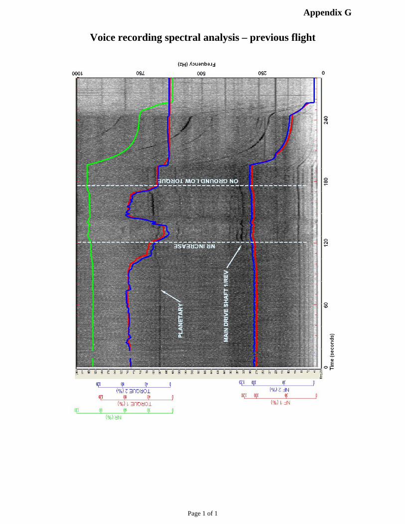
Voice recording spectral analysis – previous flight

Appendix H
Page 1 of 1
Recorded HUMS data

Page 1 of 5
Sikorsky S-61and similar types Engine/Transmission/MGB related occurrences of possible significanceRegistration
and Type VariantDate Report Type Key features Accident/Incident summary
SH-3A May 22, 1962 USN Suspect MGB Engine 2 FW, muffled explosion, eng 2 torque drop, visible fire, engine 1 FW, Nr decrease, crashSH-3A January 30,
1964USN Transmission deck
fireTransmission failure call, heavy smoke, crash
CH-3C December 2,1965
USAF #2 engine fire,bearing failure
Fire attibuted to bearing failure. Water landing at Cocoa Beach. Extinguished by crew. No furtherdetails
SH-3A August 27,1967
USN Brief in-flight fireHigh pitch hum,
bang#1 engine,
EMRST damaged,Thomas coupling
fragmented
MGB oil hot caution light. After ditching, engine FW. Sank
July 10, 1974 USAF Eng 1 power loss on approach. Landed short and consumed by fireSH-3A April 4, 1975 USN Spur gear shaft
shear due IFWU 2failure
Torque split and vibration. Eng 2 FW, Nf 120%
G-AZRFS-61N
September 16,1976
CAA OccurrenceNo. 197604142
In-flight fire(extinguished)
Loud bangEMRST severed#2 engine, #4 & 5
bearings failedBoth oil jets
fractured#5 oil jet tube bent
The No 2 engine oil pressure fell to 10 psi, followed by an indication of engine fire. The No 5 bearinghad failed, the rear support tube had separated with fire damage to the main gearbox front casing andthe wiring/hydraulic hoses damaged due to failure of the No 5 bearing oil seal. CAA Closure; Powerturbine failure due to oil starvation of No's 4 and 5 bearings
SH-3D January 30,1978
Probably incorrectspur gear journal
dimension
Squealing noise during autorotation
SH-3H March 16,1978
Suspect sleevebearing failure
Metallic odour, buzz from MGB, 14 psi oil pressure drop, No 1 input shaft loose
SH-3G April 14, 1978 Whine, chip light,Excessive play in
No 2 IDS
Spur gear journals deteriorated by improper lube and plasma spray techniques
Appendix I

Page 2 of 5
Registrationand Type Variant
Date Report Type Key features Accident/Incident summary
SH-3G October 3,1978
Loud howling, loudbang, fire
Evidence of spur gear and sleeve bearing failure caused by flange coupling/IDS
SH-3H November 28,1978
Suspect No 1 IFWfailure
High frequency vibration. Oil analysis revealed high iron
SH-3D February 21,1979
Suspect No 1 inputsection
High pitch whine, grinding
SH-3H March 13,1979
Chip lights, metalflakes
SH-3D April 6, 1979 Flange coupling outof balance
High frequency squeal
SH-3D April 27, 1979 High frequency vibration and whine. Steel particles. High temperature historySH-3H August 22,
1979Cracked 'T' bolt
SH-3A June 27, 1979 Input seal worn High porosity of spur gear plasma spray - lube problemSH-3G November 13,
1979High Frequency
vibrationSleeve bearing
destroyed
Insufficient lube and misrigged spur gear
SH-3D November 28,1979
Loud howl Lack of lube, high porosity spur gear plating
SH-3H December 3,1979
Loud thump,vibration, shudder
No 1 IFWU failed. Secondary failure of sleeve bearing
SH-3D January 17,1980
High frequency history howling from No 1 input area - not corrected by shaft change
SH-3H February 7,1980
Howling noiseExcessive radial
play in IDSSH-3H May 21, 1980 Loud howl, No 2
side of MGB failed.Fire
Possible misalignment, possible spur gear
SH-3C June 28, 1980 High pitch noise Coupling improperly greasedSH-3H November 9,
1980Noise, chip lights, oil
leakHigh speed bearing failure suspect
Appendix I

Page 3 of 5
Registrationand Type Variant
Date Report Type Key features Accident/Incident summary
SH-3H November 14,1980
Oil pressurefluctuation
No 2 input quill scored, carbon seal enlarged
SH-3G April 10, 1981 USN In-flight fire invicinity of main rotor
head
Suspect failure at No 2 engine input spur gear. A/c destroyed
SH-3G September 15,1982
USN Drive failure Transmission whine, loud bang, rotor brake caution light, engine 1 lost power, engine 1 fire warning
G-ASNLS-61N
March 11,1983
#1 input spur gearfailure
69-5804HH-3E
October, 1985 USAF In-flight fireEMRST severed
#2 engine, #5bearing failed
PT disc uncontained
AAIB report 3/90 describes ‘almost identical damage in some areas to that seen on G-BEID’s No 2drive train
G-LINKS-61N
January 17,1986
CAA OccurrenceNo. 198600154
Whine, bang#1 engine
EMRST damagedThomas cplgdisintegrated
There was an uncontrolled failure of the high speed shaft engine to transmission. After normal start, amedium-high frequency whine developed, which soon increased in volume and frequency. As shut-down procedures were carried out a bang was heard, this seemed to be suggestive of high speedshaft failure. Primary failure resulted in separation of the high speed shaft from the MGB input flange,disintegration of the Thomas coupling at the forward end of the high speed shaft and separation of theinput coupling from the MGB. Sikorsky reports that the shaft failure could have been due to a deviationfrom approved repair scheme in that the MGB input housing was secured with light alloy pins insteadof steel
G-BEIDS-61N
July 13, 1988 AAR 3/90 In-flight fireUnusual noises,
bangEMRST severed
Polygon cplgmisassembled#2 engine, #5bearing failedBoth oil jets
fractured
A muffled crack or ‘bang’ was heard by the co-pilot 43 minutes into the flight. Passengers then heard anumber of abnormal noises including a grinding mechanical noise. Both crew felt a slight change inthe vibratory “feel” of the aircraft, which was followed by a fire in the main gearbox bay. The PT anddrive train of No 2 engine had suffered significant pre-shutdown damage. This consisted of severedamage to No 5 bearing, extensive rubbing between rotating and static parts of the PT module, andsevere rubbing of the Thomas coupling against the EMRSA, which had resulted in severance of thelatter. The No 5 bearing deterioration resulted from failure of the bearing cage, or by excessiveimbalance forces on the bearing. The accident was caused by an uncontrollable fire in the maingearbox bay, which probably resulted from the effects of failure of the No 5 bearing in the No 2 engine.The aircraft ditched in the North Sea, 29 nm North East of Sumburgh, Shetland. The 2 crew and 19passengers were evacuated successfully, without serious injury A
ppendix I

Page 4 of 5
Registrationand Type Variant
Date Report Type Key features Accident/Incident summary
G-BDESS-61N
November 10,1988
AAR 1/90 In a low hover, after takeoff, a buzzing noise was heard, followed by a thump in the passenger cabinand an increase in vibration. There was then a loss of the main transmission oil pressure. Theaccident resulted from progressive failure in the main transmission, initiated by a fatigue fracture of asingle tooth on the main combiner gear wheel. The helicopter suffered a catastrophic failure of thehelical combiner gear within it’s main transmission input gear train, which occured after 3.875 hours ofoperation. The fatigue cracking that originated in a gear tooth, was in a tooth zone containing non-metallic inclusions. The aircraft ditched in the North sea, 90nm North East of Aberdeen. The 2 crewand 11 passengers evacuated the aircraft and were rescued without injury
G-BCEAS-61N
February 23,1989
CAA OccurrenceNo. 198900539
A hammering vibration was felt from the main rotor at a maximum speed of 98kts and 65% torque.The hammering vibration was repeated every 30 seconds in moderate turbulance. A heavyaccumulation of salt was confirmed as the cause
61786S-61N
February 28,1989
Brief in-flight fireHigh pitch hum,
bang#1 engine,
EMRST damaged,Thomas coupling
fragmented
Far east MHS S-61N Thomas coupling fragmented. IDS splined coupling separated. IP journaleccentric damage and fractured. Plain bearing grossly damaged and rotated. AAIB thought this wasdue to a ‘T’ bolt coming loose. At the time self locking nuts were being re-used without checking therun-on torque
G-BFFJS-61N
May 11, 1989 Bulletin 7/90Jul-90
Whine, then bang#1 IDS aft flange
damage
Five minutes after engine start an abnormal whining noise was heard, which soon culminated in a loudbang. The crew on an adjacent S-61 noticed a quantity of oil running down the left side of G-BFFJ’sfuselage. The aircraft's passengers later reported hearing the noise for some time before the bang.Examination of the aircraft revealed that the No 1 input pinion and IDS had fractured. The Thomascoupling had fragmented, the IDS had separated from the splined coupling, the EMRSA had beendamaged, the gimbal ring had fractured and the No.1 input pinion forward journal had fractured. Therehad been reports of oil leaks from the No 1 input area on two other occasions before the incident. Itwas possible that damage had resulted from a temporary seating failure of the No 1 input pinion oilseal some time before the incident, although no positive evidence was present. The aircraft had notdeparted from Sumburgh Airport, Shetland Islands. All persons on board were evacuated and noinjuries were sustained
G-BEDIS-61N
May 1, 1990 Unobtainable No report was found. The report on S-61, G-BCLD uses this aircraft as one of the 'other cases' foundwith similar/relevant problems: In this case the MGB was bought by a UK operator as part of a usedS-61N that was transferred from the USA. On arrival in the UK abnormal debris was found in the MGBscavenge filter, including white metal. Strip examination reportedly showed that the aft bearing for theNo 1 input pinion was severely distressed. Part of the journal had flaked off; the sleeve bearing wasloose in its sleeve and had turned; the sleeve was loose in the housing bore; and the sleeve locationpin was loose. During test-running on a rig following repair the No 1 input pinion failed
Appendix I

Page 5 of 5
Registrationand Type Variant
Date Report Type Key features Accident/Incident summary
G-BCLDS-61N
October 9,1990
Bulletin 12/91Dec-91
No fireWhine, then bang#1 IDS 3 ‘T’ bolts
torn offminor damage to
enginelive oil jet cracked
dead oil jet fractured
Five minutes into the flight, as transmission torque was increased, the crew heard a whine. This wasidentified as coming from the left side of the transmission. Around one minute after the whine washeard initially, there was a loud bang. Power was lost and the No 1 engine shutdown. After landing,oil was seen pouring down the left side of the aircraft. Prior to the oil leak, the crew noted a slight risein MGB oil temperature and a slight fall in the oil pressure but both parameters remained within limits.This tendency continued during subsequent flights and immediately prior to the accident. The No 1drive train input pinion and the IDS/splined flange connection had fractured. This forward journalexhibited gross rotational wear, deformation and overheat. The engine exhibited considerable damageconsistent with the effects of excessive vibration. The crew established the aircraft in autorotation andachieved a gentle landing 5 nm East of Mount Pleasant Airport, Falkland Islands. The 3 crew and 14passengers evacuated the aircraft without difficulty
G-AYOYS-61N
November 5,1990
CAA OccurrenceNo. 199002052
The right-hand aft transmission support STA 290 was found to be cracked during maintenance. Thisseemed to have been caused by internal stresses induced into the structure by incorrect maintenancepractice
? ? Gearbox 943 IPfractured during
ground rig run afterrepair
Reported due to external oil line kink - see G-BEDI above (same gearbox)
G-BDDAS-61N
November 6,1990
CAA OccurrenceNo. 199004924
During a mid-point inspection, unauthorised repairs were found to have been carried out on the maingearbox. On No's 1 and 2 input spur gears unauthorised blending repairs were found in the gear teethcrowns. The helical input gear had been repaired beyond authority on 4 gear teeth, both sides of thecrown. No 1 input gear white metal bearing was damaged and worn to copper base lining togetherwith surface cracks on the rear bearing journal. Repairs to both white metal bearing housing bosseswere not re-protected. It was confirmed that when these repairs were carried out an incorrect sizedNo 1 aft bearing had been fitted, which resulted in damage to other parts
C-FFHDS-61N
December 16,2002
TSB underinvestigation
#1 input pinionfractured, IDS bent
4 degrees
Test flight to adjust topping of #2 engine. Logging operation. During climbout, whine and vibrationnoted. Smoke in cabin. Flames seen, bang and shudder. A/c autorotated to safe landing on road, butstruck power lines. Severe damage to a/c. #1 input pinion journal and carbon seal disintegrated,pinion fractured, severe gimbal rub. All four 'T' bolts in place
N81664S-61A
March 23,2003
Lloyds List 26-3-03 Hovering at 200ft, load bang and smoke reported. A/c dropped to the ground and was destroyed
EMRSA Engine Mounting Rear Support AssemblyIDS Input Drive Shaft
IFWU Input Free Wheel UnitIP Input Pinion
MGB Main Gear BoxSC Splined Coupling
Appendix I

Appendix J
Page 1 of 1
Reproduced with acknowledgements

Appendix K
Page 1 of 2
Information prepared by GE Aircraft Engines
Reproduced with acknowledgements
Oil Tube Stress Levels

Appendix K
Page 2 of 2
Information prepared by GE Aircraft Engines
Reproduced with acknowledgements

Appendix L
Page 1 of 1
Distribution of Bearing Related Events
Information prepared by Sikorsky AircraftReproduced with acknowledgements

Appendix M
Page 1 of 4

Appendix M
Page 2 of 4

Appendix M
Page 3 of 4

Appendix M
Page 4 of 4

Appendix N
Page 1 of 4
Safety Recommendations issued during the Investigation

Appendix N
Page 2 of 4
Appendix N
Page 3 of 4

Appendix N
Page 4 of 4

Appendix O
Page 1 of 4
CAA and FAA Responsesto AAIB Safety Recommendations 2002-51, 2002-52 and 2002-53

Appendix O
Page 2 of 4

Appendix O
Page 3 of 4

Appendix O
Page 4 of 4

Appendix P
Page 1 of 5
FINITE ELEMENT AND DYNAMIC ANALYSISOF MAIN DRIVE SHAFT
DRIVE SHAFT ROTORDYNAMIC MODEL
Appendix P
Page 2 of 5
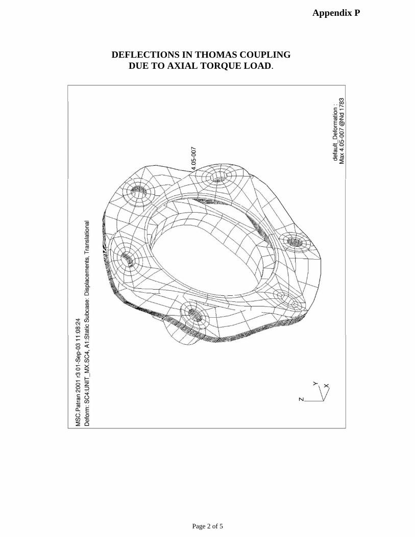
DEFLECTIONS IN THOMAS COUPLINGDUE TO AXIAL TORQUE LOAD.

Appendix P
Page 3 of 5
First whirl mode
TYPICAL CAMPBELL DIAGRAM FOR THE SYSTEM SHOWINGWHIRL MODE AT THE NATURAL FREQUENCY

Appendix P
Page 4 of 5
Assumptions: K4 = 0.8×10⁶lbf/in K5 = 0.5×10⁶lbf/in;0.001 ins mass offset at turbine wheel
TYPICAL UNBALANCE RESPONSE DIAGRAMS

Appendix P
Page 5 of 5
Whirl mode shape
The left of the diagram shows nodes for bearings 4 and 5,the pinion journals are to the right