fz8 - service manual
TRANSCRIPT
8/21/2019 Fz8 - Service Manual
http://slidepdf.com/reader/full/fz8-service-manual 1/609
SERVICE MANUAL
FZ8NA
FZ8SA
2011
8/21/2019 Fz8 - Service Manual
http://slidepdf.com/reader/full/fz8-service-manual 2/609
8/21/2019 Fz8 - Service Manual
http://slidepdf.com/reader/full/fz8-service-manual 3/609
EAS20071
IMPORTANTThis manual was produced by the Yamaha Motor Company, Ltd. primarily for use by Yamaha deal-ers and their qualified mechanics. It is not possible to include all the knowledge of a mechanic in onemanual. Therefore, anyone who uses this book to perform maintenance and repairs on Yamahavehicles should have a basic understanding of mechanics and the techniques to repair these typesof vehicles. Repair and maintenance work attempted by anyone without this knowledge is likely torender the vehicle unsafe and unfit for use.Yamaha Motor Company, Ltd. is continually striving to improve all of its models. Modifications and
significant changes in specifications or procedures will be forwarded to all authorized Yamaha deal-ers and will appear in future editions of this manual where applicable.
TIP
Designs and specifications are subject to change without notice.
EAS20081
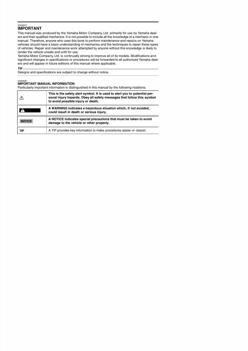
IMPORTANT MANUAL INFORMATIONParticularly important information is distinguished in this manual by the following notations.
This is the safety alert symbol. It is used to alert you to potential per-sonal injury hazards. Obey all safety messages that follow this symbolto avoid possible injury or death.
A WARNING indicates a hazardous situation which, if not avoided,could result in death or serious injury.
A NOTICE indicates special precautions that must be taken to avoid
damage to the vehicle or other property.
A TIP provides key information to make procedures easier or clearer.
WARNING
8/21/2019 Fz8 - Service Manual
http://slidepdf.com/reader/full/fz8-service-manual 4/609
EAS20091
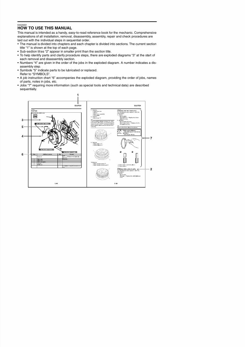
HOW TO USE THIS MANUALThis manual is intended as a handy, easy-to-read reference book for the mechanic. Comprehensiveexplanations of all installation, removal, disassembly, assembly, repair and check procedures arelaid out with the individual steps in sequential order. The manual is divided into chapters and each chapter is divided into sections. The current section
title “1” is shown at the top of each page.• Sub-section titles “2” appear in smaller print than the section title.• To help identify parts and clarify procedure steps, there are exploded diagrams “3” at the start of
each removal and disassembly section.• Numbers “4” are given in the order of the jobs in the exploded diagram. A number indicates a dis-assembly step.
• Symbols “5” indicate parts to be lubricated or replaced.
Refer to “SYMBOLS”.• A job instruction chart “6” accompanies the exploded diagram, providing the order of jobs, names
of parts, notes in jobs, etc.• Jobs “7” requiring more information (such as special tools and technical data) are described
sequentially.
8/21/2019 Fz8 - Service Manual
http://slidepdf.com/reader/full/fz8-service-manual 5/609
EAS20101
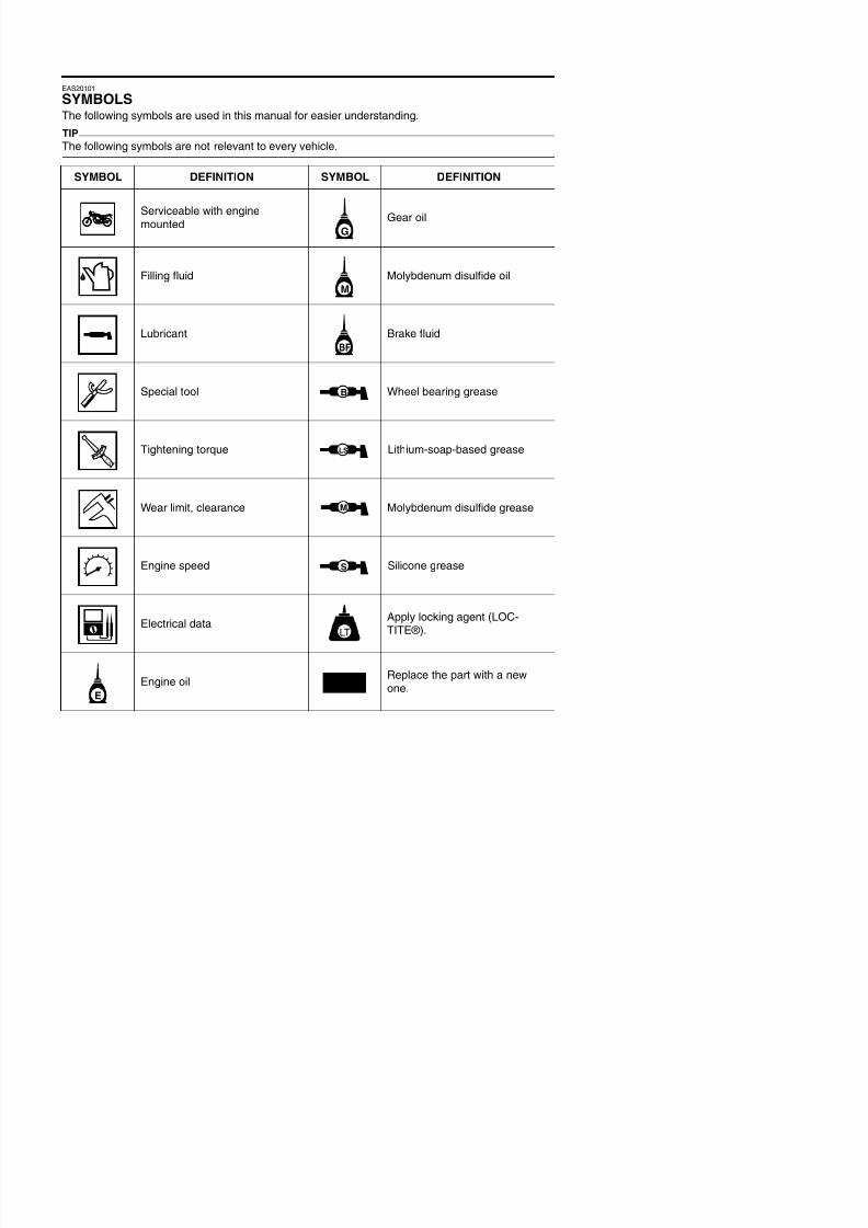
SYMBOLSThe following symbols are used in this manual for easier understanding.
TIP
The following symbols are not relevant to every vehicle.
SYMBOL DEFINITION SYMBOL DEFINITION
Serviceable with enginemounted Gear oil
Filling fluid Molybdenum disulfide oil
Lubricant Brake fluid
Special tool Wheel bearing grease
Tightening torque Lithium-soap-based grease
Wear limit, clearance Molybdenum disulfide grease
Engine speed Silicone grease
G
M
BF
B
T R .
.
LS
M
S

8/21/2019 Fz8 - Service Manual
http://slidepdf.com/reader/full/fz8-service-manual 6/609
8/21/2019 Fz8 - Service Manual
http://slidepdf.com/reader/full/fz8-service-manual 7/609
1
2
34
5
67
EAS20110
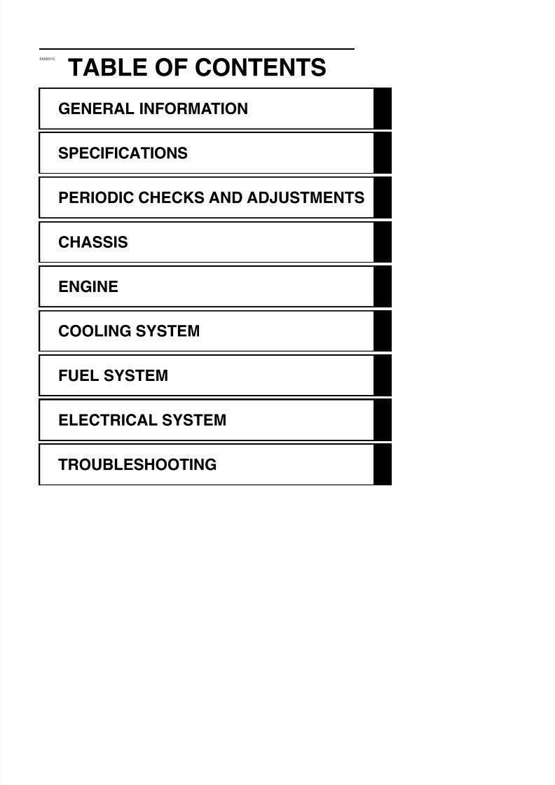
TABLE OF CONTENTSGENERAL INFORMATION
SPECIFICATIONS
PERIODIC CHECKS AND ADJUSTMENTS
CHASSIS
ENGINE
COOLING SYSTEM
FUEL SYSTEM

8/21/2019 Fz8 - Service Manual
http://slidepdf.com/reader/full/fz8-service-manual 8/609
8/21/2019 Fz8 - Service Manual
http://slidepdf.com/reader/full/fz8-service-manual 9/609
1
GENERAL INFORMATION
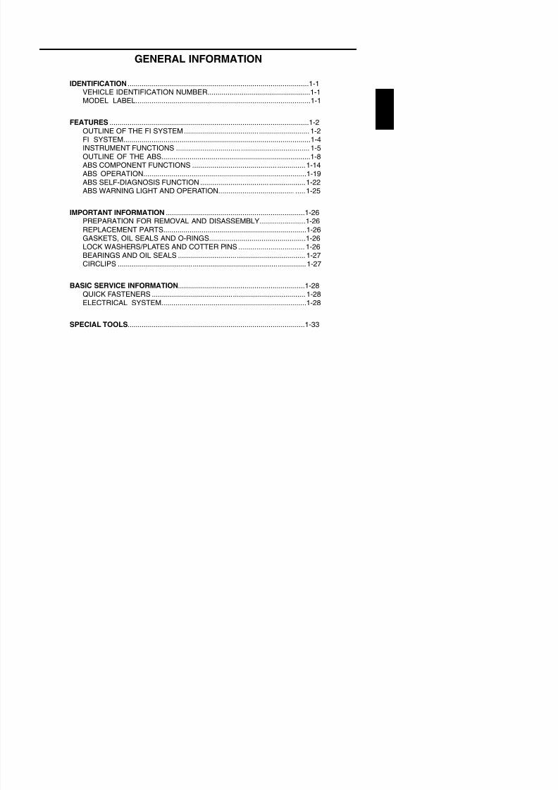
IDENTIFICATION ..........................................................................................1-1VEHICLE IDENTIFICATION NUMBER...................................................1-1MODEL LABEL.......................................................................................1-1
FEATURES ...................................................................................................1-2
OUTLINE OF THE FI SYSTEM.............................................................. 1-2
FI SYSTEM.............................................................................................1-4INSTRUMENT FUNCTIONS .................................................................. 1-5OUTLINE OF THE ABS..........................................................................1-8ABS COMPONENT FUNCTIONS ........................................................1-14ABS OPERATION.................................................................................1-19ABS SELF-DIAGNOSIS FUNCTION ....................................................1-22ABS WARNING LIGHT AND OPERATION...........................................1-25
IMPORTANT INFORMATION .....................................................................1-26PREPARATION FOR REMOVAL AND DISASSEMBLY........................1-26
REPLACEMENT PARTS.......................................................................1-26GASKETS, OIL SEALS AND O-RINGS................................................1-26LOCK WASHERS/PLATES AND COTTER PINS ................................. 1-26BEARINGS AND OIL SEALS ............................................................... 1-27CIRCLIPS .............................................................................................1-27
BASIC SERVICE INFORMATION...............................................................1-28QUICK FASTENERS ............................................................................ 1-28ELECTRICAL SYSTEM........................................................................1-28
SPECIAL TOOLS........................................................................................1-33
8/21/2019 Fz8 - Service Manual
http://slidepdf.com/reader/full/fz8-service-manual 10/609
IDENTIFICATION
EAS20130
IDENTIFICATION
EAS20140
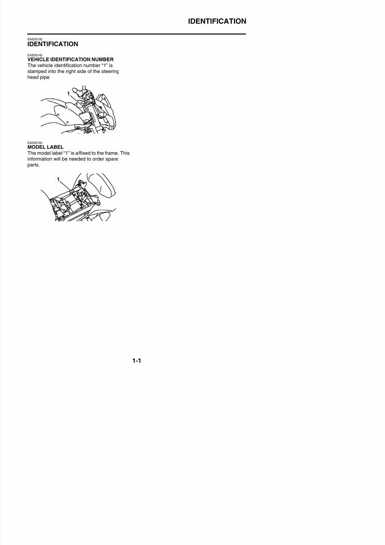
VEHICLE IDENTIFICATION NUMBERThe vehicle identification number “1” isstamped into the right side of the steeringhead pipe.
EAS20150MODEL LABEL
The model label “1” is affixed to the frame. Thisinformation will be needed to order spareparts.
8/21/2019 Fz8 - Service Manual
http://slidepdf.com/reader/full/fz8-service-manual 11/609
FEATURES
EAS20170
FEATURES
EAS39P1101
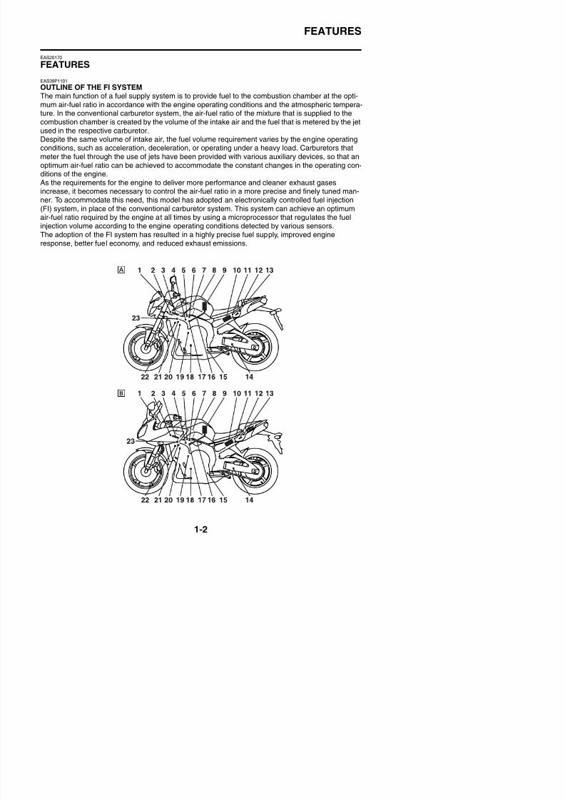
OUTLINE OF THE FI SYSTEMThe main function of a fuel supply system is to provide fuel to the combustion chamber at the opti-mum air-fuel ratio in accordance with the engine operating conditions and the atmospheric tempera-ture. In the conventional carburetor system, the air-fuel ratio of the mixture that is supplied to thecombustion chamber is created by the volume of the intake air and the fuel that is metered by the jetused in the respective carburetor.
Despite the same volume of intake air, the fuel volume requirement varies by the engine operatingconditions, such as acceleration, deceleration, or operating under a heavy load. Carburetors thatmeter the fuel through the use of jets have been provided with various auxiliary devices, so that anoptimum air-fuel ratio can be achieved to accommodate the constant changes in the operating con-ditions of the engine.As the requirements for the engine to deliver more performance and cleaner exhaust gasesincrease, it becomes necessary to control the air-fuel ratio in a more precise and finely tuned man-ner. To accommodate this need, this model has adopted an electronically controlled fuel injection
(FI) system, in place of the conventional carburetor system. This system can achieve an optimumair-fuel ratio required by the engine at all times by using a microprocessor that regulates the fuelinjection volume according to the engine operating conditions detected by various sensors.The adoption of the FI system has resulted in a highly precise fuel supply, improved engineresponse, better fuel economy, and reduced exhaust emissions.
8/21/2019 Fz8 - Service Manual
http://slidepdf.com/reader/full/fz8-service-manual 12/609
FEATURES
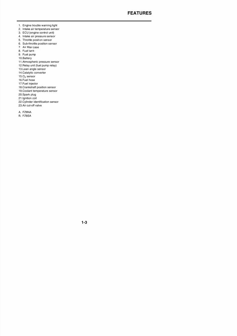
1. Engine trouble warning light
2. Intake air temperature sensor3. ECU (engine control unit)
4. Intake air pressure sensor
5. Throttle position sensor
6. Sub-throttle position sensor
7. Air filter case
8. Fuel tank
9. Fuel pump
10.Battery11.Atmospheric pressure sensor
12.Relay unit (fuel pump relay)
13.Lean angle sensor
14.Catalytic converter
15.O2 sensor
16.Fuel hose
17.Fuel injector
18.Crankshaft position sensor19.Coolant temperature sensor
20.Spark plug
21.Ignition coil
22.Cylinder identification sensor
23.Air cut-off valve
A. FZ8NA
B. FZ8SA
8/21/2019 Fz8 - Service Manual
http://slidepdf.com/reader/full/fz8-service-manual 13/609
FEATURES
EAS39P1102
FI SYSTEM
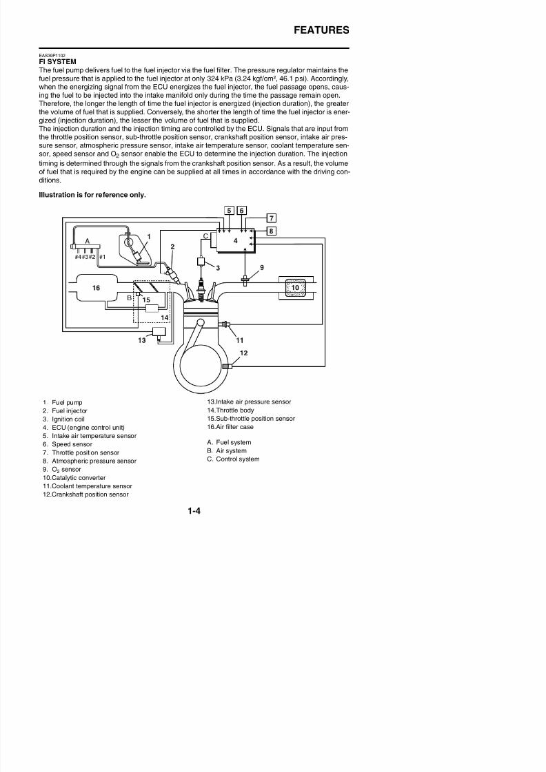
The fuel pump delivers fuel to the fuel injector via the fuel filter. The pressure regulator maintains thefuel pressure that is applied to the fuel injector at only 324 kPa (3.24 kgf/cm², 46.1 psi). Accordingly,when the energizing signal from the ECU energizes the fuel injector, the fuel passage opens, caus-ing the fuel to be injected into the intake manifold only during the time the passage remain open.Therefore, the longer the length of time the fuel injector is energized (injection duration), the greaterthe volume of fuel that is supplied. Conversely, the shorter the length of time the fuel injector is ener-gized (injection duration), the lesser the volume of fuel that is supplied.The injection duration and the injection timing are controlled by the ECU. Signals that are input from
the throttle position sensor, sub-throttle position sensor, crankshaft position sensor, intake air pres-sure sensor, atmospheric pressure sensor, intake air temperature sensor, coolant temperature sen-sor, speed sensor and O2 sensor enable the ECU to determine the injection duration. The injection
timing is determined through the signals from the crankshaft position sensor. As a result, the volumeof fuel that is required by the engine can be supplied at all times in accordance with the driving con-
ditions.
Illustration is for reference only.
8/21/2019 Fz8 - Service Manual
http://slidepdf.com/reader/full/fz8-service-manual 14/609
FEATURES
EAS39P1103
INSTRUMENT FUNCTIONS
Multi-function meter unit
WARNING
EWA12422
Be sure to stop the vehicle before makingany setting changes to the multi-functionmeter unit. Changing settings while riding
can distract the operator and increase therisk of an accident.
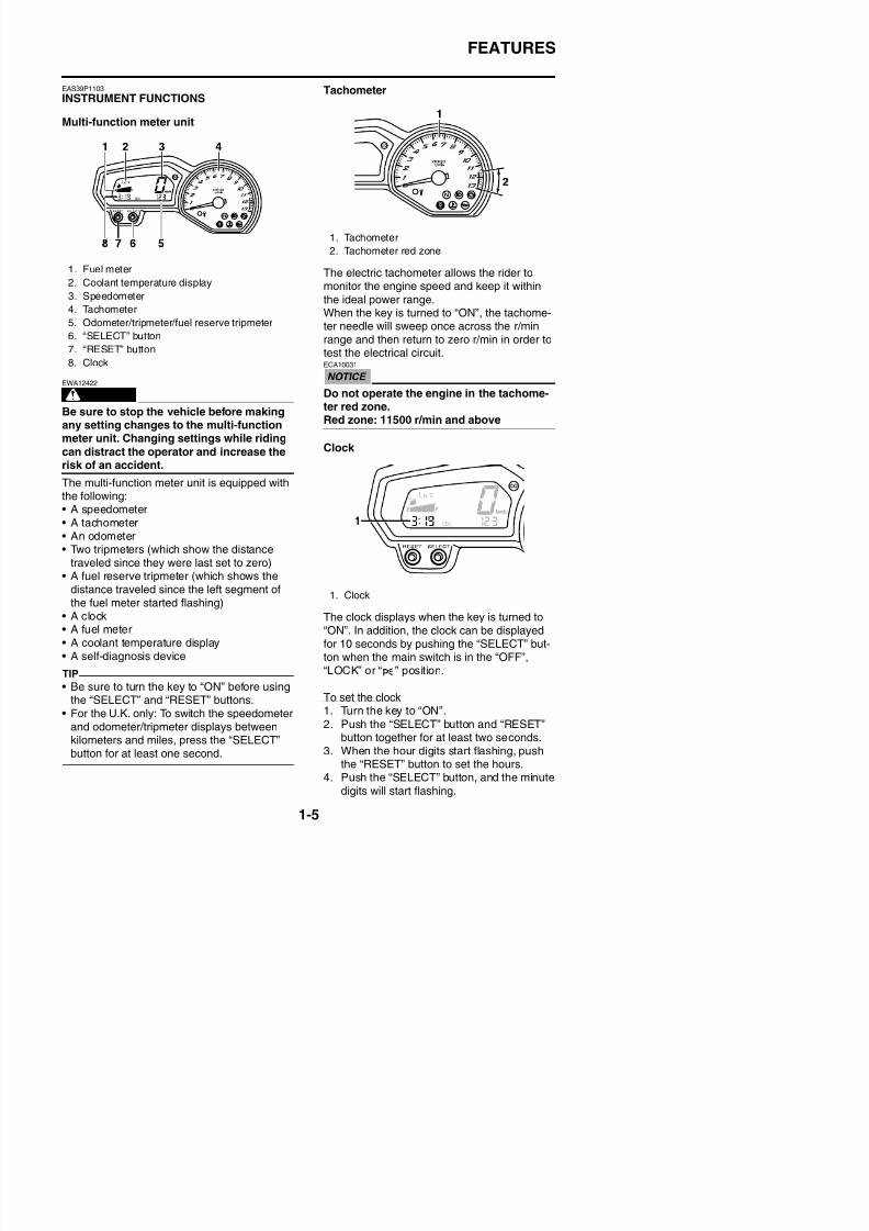
The multi-function meter unit is equipped withthe following:• A speedometer• A tachometer
• An odometer• Two tripmeters (which show the distance
traveled since they were last set to zero)• A fuel reserve tripmeter (which shows the
distance traveled since the left segment ofthe fuel meter started flashing)
Tachometer
The electric tachometer allows the rider tomonitor the engine speed and keep it within
the ideal power range.When the key is turned to “ON”, the tachome-
ter needle will sweep once across the r/minrange and then return to zero r/min in order totest the electrical circuit.ECA10031
Do not operate the engine in the tachome-ter red zone.Red zone: 11500 r/min and above
Clock
1. Fuel meter
2. Coolant temperature display
3. Speedometer
4. Tachometer
5. Odometer/tripmeter/fuel reserve tripmeter6. “SELECT” button
7. “RESET” button
8. Clock
1. Tachometer
2. Tachometer red zone
1. Clock
8/21/2019 Fz8 - Service Manual
http://slidepdf.com/reader/full/fz8-service-manual 15/609
FEATURES
5. Push the “RESET” button to set the min-utes.
6. Push the “SELECT” button and thenrelease it to start the clock.
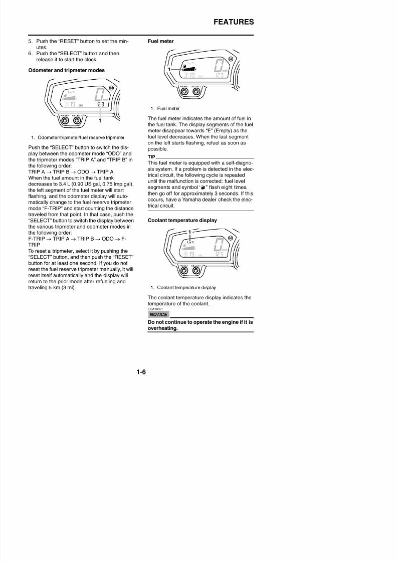
Odometer and tripmeter modes
Push the “SELECT” button to switch the dis-play between the odometer mode “ODO” andthe tripmeter modes “TRIP A” and “TRIP B” inthe following order:TRIP A → TRIP B → ODO → TRIP AWhen the fuel amount in the fuel tankdecreases to 3.4 L (0.90 US gal, 0.75 Imp.gal),
the left segment of the fuel meter will start
flashing, and the odometer display will auto-matically change to the fuel reserve tripmetermode “F-TRIP” and start counting the distancetraveled from that point. In that case, push the“SELECT” button to switch the display betweenthe various tripmeter and odometer modes inthe following order:F-TRIP → TRIP A → TRIP B → ODO → F-
TRIPTo reset a tripmeter, select it by pushing the“SELECT” button, and then push the “RESET”button for at least one second. If you do notreset the fuel reserve tripmeter manually, it willreset itself automatically and the display will
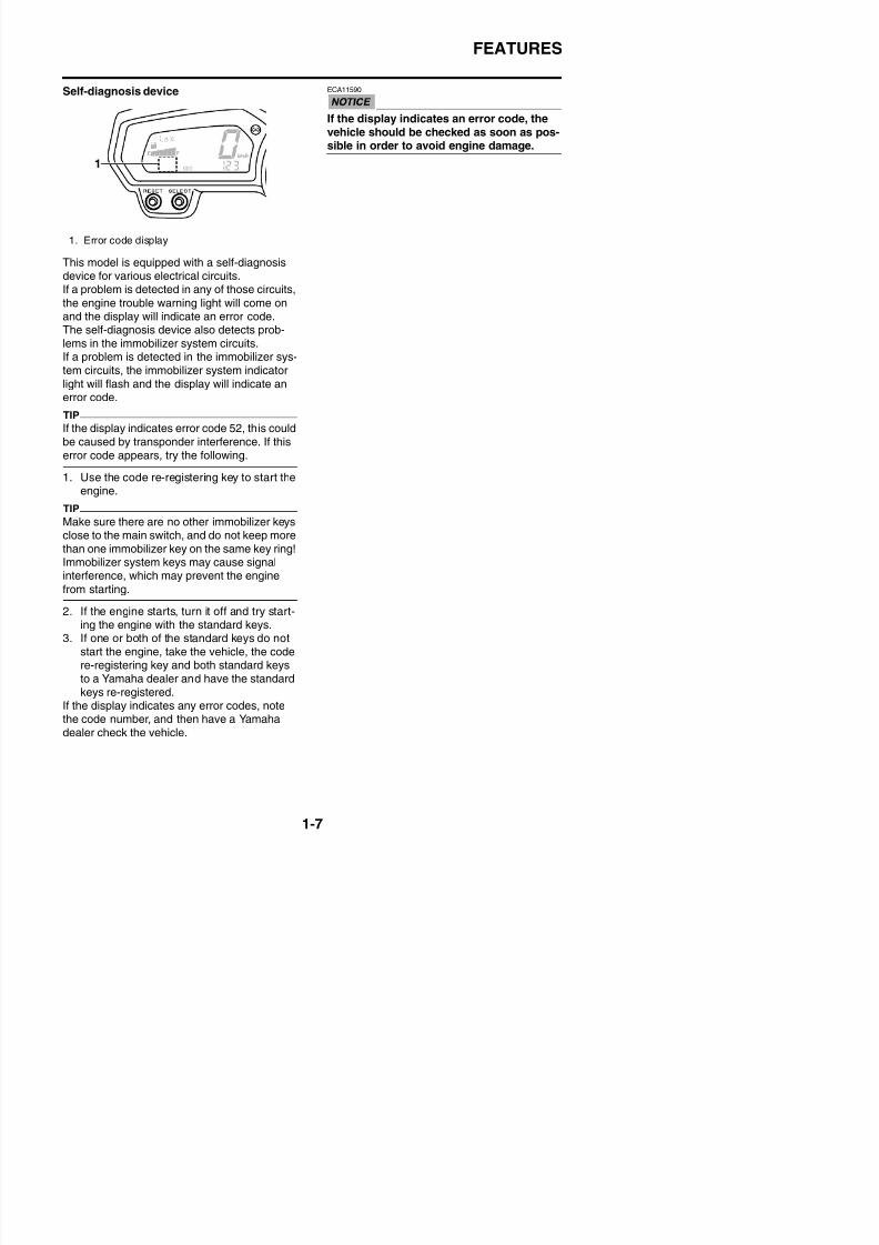
Fuel meter
The fuel meter indicates the amount of fuel inthe fuel tank. The display segments of the fuelmeter disappear towards “E” (Empty) as the
fuel level decreases. When the last segmenton the left starts flashing, refuel as soon as
possible.
TIP
This fuel meter is equipped with a self-diagno-
sis system. If a problem is detected in the elec-trical circuit, the following cycle is repeateduntil the malfunction is corrected: fuel levelsegments and symbol “ ” flash eight times,
then go off for approximately 3 seconds. If thisoccurs, have a Yamaha dealer check the elec-trical circuit.
Coolant temperature display
1. Odometer/tripmeter/fuel reserve tripmeter
1. Fuel meter
8/21/2019 Fz8 - Service Manual
http://slidepdf.com/reader/full/fz8-service-manual 16/609
FEATURES
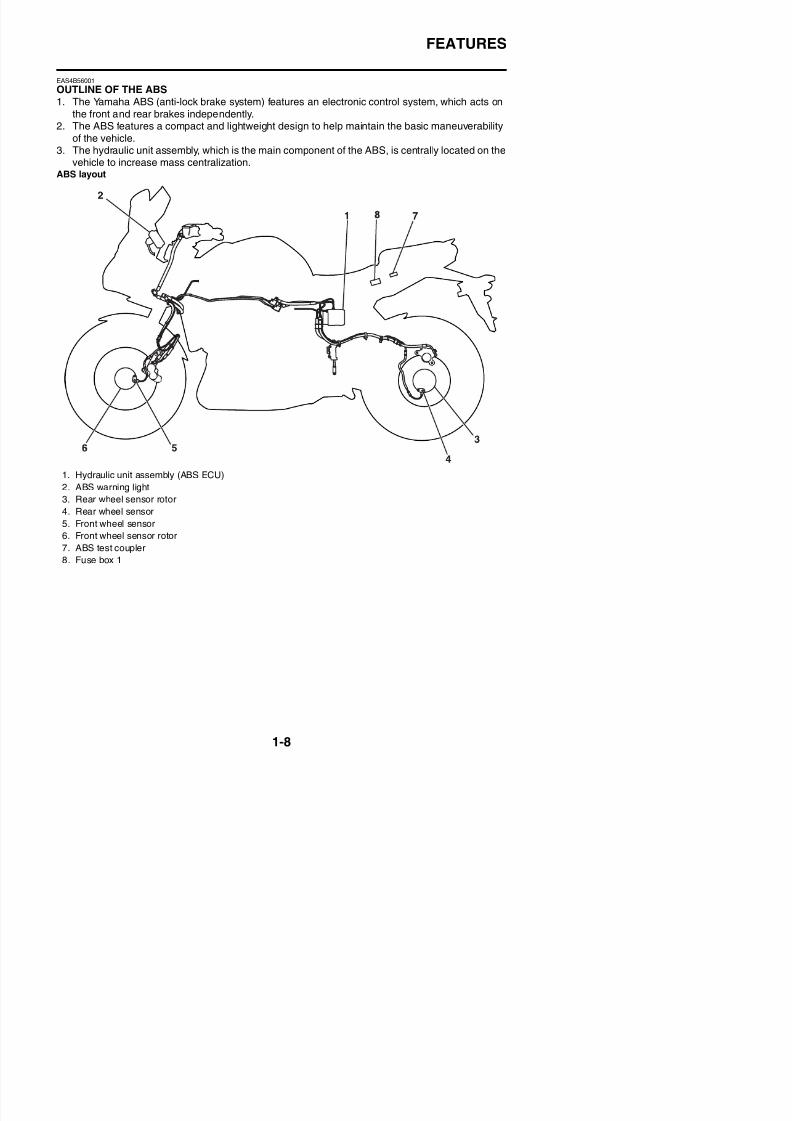
Self-diagnosis device
This model is equipped with a self-diagnosisdevice for various electrical circuits.If a problem is detected in any of those circuits,
the engine trouble warning light will come onand the display will indicate an error code.
The self-diagnosis device also detects prob-lems in the immobilizer system circuits.If a problem is detected in the immobilizer sys-tem circuits, the immobilizer system indicatorlight will flash and the display will indicate anerror code.
TIP
If the display indicates error code 52, this couldbe caused by transponder interference. If thiserror code appears, try the following.
1. Use the code re-registering key to start theengine.
TIP
Make sure there are no other immobilizer keysclose to the main switch, and do not keep more
than one immobilizer key on the same key ring!Immobilizer system keys may cause signalinterference, which may prevent the engine
from starting.
2. If the engine starts, turn it off and try start-
ECA11590
If the display indicates an error code, thevehicle should be checked as soon as pos-sible in order to avoid engine damage.
1. Error code display
8/21/2019 Fz8 - Service Manual
http://slidepdf.com/reader/full/fz8-service-manual 17/609
FEATURES
EAS4B56001
OUTLINE OF THE ABS
1. The Yamaha ABS (anti-lock brake system) features an electronic control system, which acts onthe front and rear brakes independently.
2. The ABS features a compact and lightweight design to help maintain the basic maneuverabilityof the vehicle.
3. The hydraulic unit assembly, which is the main component of the ABS, is centrally located on thevehicle to increase mass centralization.
ABS layout
1. Hydraulic unit assembly (ABS ECU)
2. ABS warning light3. Rear wheel sensor rotor
4. Rear wheel sensor
5. Front wheel sensor
6. Front wheel sensor rotor
7. ABS test coupler

8/21/2019 Fz8 - Service Manual
http://slidepdf.com/reader/full/fz8-service-manual 18/609
FEATURES
ABSThe operation of the Yamaha ABS brakes is the same as conventional brakes on other vehicles, witha front brake lever for operating the front brake and a rear brake pedal for operating the rear brake.When wheel lock is detected during emergency braking, hydraulic control is performed by thehydraulic system on the front and rear brakes independently.
Useful terms• Wheel speed:
The rotation speed of the front and rear wheels.• Chassis speed:
The speed of the chassis.When the brakes are applied, wheel speed and chassis speed are reduced. However, the chassistravels forward by its inertia even though the wheel speed is reduced.
• Brake force:The force applied by braking to reduce the wheel speed.
• Wheel lock:A condition that occurs when the rotation of one or both of the wheels has stopped, but the vehiclecontinues to travel.
• Side force:The force on the tires which supports the vehicle when cornering.
• Slip ratio:When the brakes are applied, slipping occurs between the tires and the road surface. This causesa difference between the wheel speed and the chassis speed.Slip ratio is the value that shows the rate of wheel slippage and is defined by the following formula.
0%: There is no slipping between the wheel and the road surface. The chassis speed is equal tothe wheel speed.100%: The wheel speed is “0”, but the chassis is moving (i.e., wheel lock).
Slip ratio =
Chassis speed –Wheel speed ×
100 (%)Chassis speed
8/21/2019 Fz8 - Service Manual
http://slidepdf.com/reader/full/fz8-service-manual 19/609
FEATURES
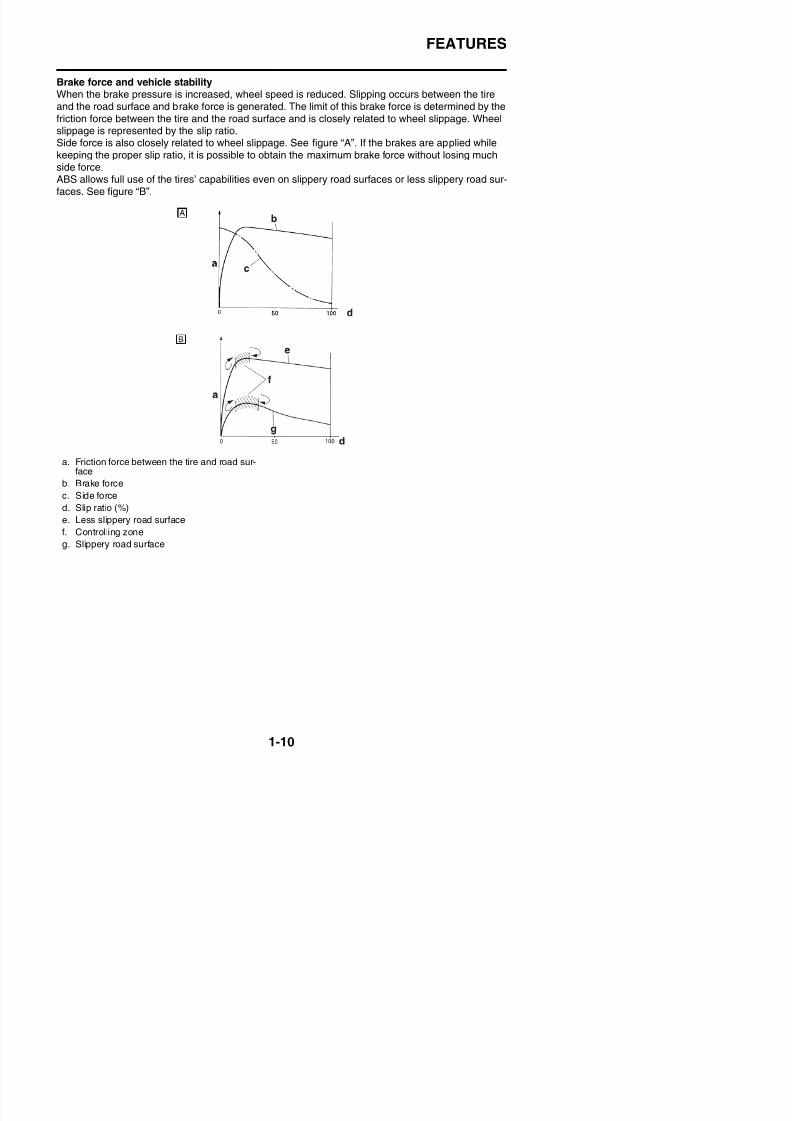
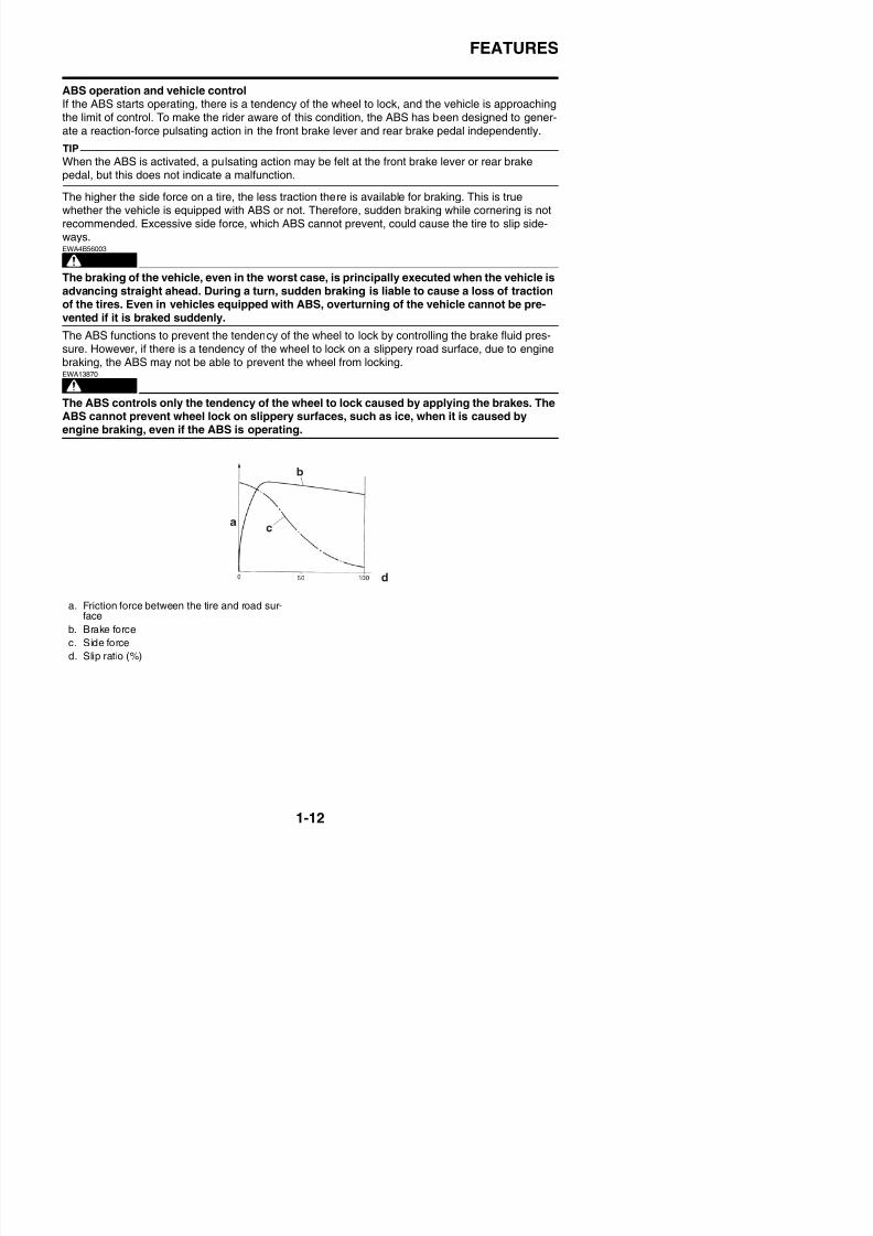
Brake force and vehicle stabilityWhen the brake pressure is increased, wheel speed is reduced. Slipping occurs between the tireand the road surface and brake force is generated. The limit of this brake force is determined by thefriction force between the tire and the road surface and is closely related to wheel slippage. Wheelslippage is represented by the slip ratio.Side force is also closely related to wheel slippage. See figure “A”. If the brakes are applied whilekeeping the proper slip ratio, it is possible to obtain the maximum brake force without losing muchside force.ABS allows full use of the tires’ capabilities even on slippery road surfaces or less slippery road sur-faces. See figure “B”.
a. Friction force between the tire and road sur-face
b. Brake force
c. Side force
d. Slip ratio (%)
e. Less slippery road surface
f. Controlling zone
g. Slippery road surface
8/21/2019 Fz8 - Service Manual
http://slidepdf.com/reader/full/fz8-service-manual 20/609
FEATURES
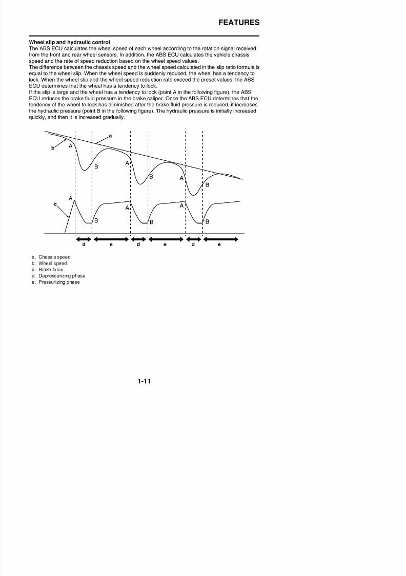
Wheel slip and hydraulic controlThe ABS ECU calculates the wheel speed of each wheel according to the rotation signal receivedfrom the front and rear wheel sensors. In addition, the ABS ECU calculates the vehicle chassisspeed and the rate of speed reduction based on the wheel speed values.The difference between the chassis speed and the wheel speed calculated in the slip ratio formula isequal to the wheel slip. When the wheel speed is suddenly reduced, the wheel has a tendency tolock. When the wheel slip and the wheel speed reduction rate exceed the preset values, the ABSECU determines that the wheel has a tendency to lock.If the slip is large and the wheel has a tendency to lock (point A in the following figure), the ABSECU reduces the brake fluid pressure in the brake caliper. Once the ABS ECU determines that thetendency of the wheel to lock has diminished after the brake fluid pressure is reduced, it increasesthe hydraulic pressure (point B in the following figure). The hydraulic pressure is initially increasedquickly, and then it is increased gradually.
a. Chassis speed
b. Wheel speed
c. Brake force
d. Depressurizing phase
e. Pressurizing phase
8/21/2019 Fz8 - Service Manual
http://slidepdf.com/reader/full/fz8-service-manual 21/609
FEATURES
ABS operation and vehicle controlIf the ABS starts operating, there is a tendency of the wheel to lock, and the vehicle is approachingthe limit of control. To make the rider aware of this condition, the ABS has been designed to gener-ate a reaction-force pulsating action in the front brake lever and rear brake pedal independently.
TIP
When the ABS is activated, a pulsating action may be felt at the front brake lever or rear brakepedal, but this does not indicate a malfunction.
The higher the side force on a tire, the less traction there is available for braking. This is truewhether the vehicle is equipped with ABS or not. Therefore, sudden braking while cornering is not
recommended. Excessive side force, which ABS cannot prevent, could cause the tire to slip side-ways.
WARNING
EWA4B56003
The braking of the vehicle, even in the worst case, is principally executed when the vehicle isadvancing straight ahead. During a turn, sudden braking is liable to cause a loss of tractionof the tires. Even in vehicles equipped with ABS, overturning of the vehicle cannot be pre-vented if it is braked suddenly.
The ABS functions to prevent the tendency of the wheel to lock by controlling the brake fluid pres-sure. However, if there is a tendency of the wheel to lock on a slippery road surface, due to enginebraking, the ABS may not be able to prevent the wheel from locking.
WARNING
EWA13870
The ABS controls only the tendency of the wheel to lock caused by applying the brakes. TheABS cannot prevent wheel lock on slippery surfaces, such as ice, when it is caused by
engine braking, even if the ABS is operating.
a. Friction force between the tire and road sur-f
8/21/2019 Fz8 - Service Manual
http://slidepdf.com/reader/full/fz8-service-manual 22/609
FEATURES
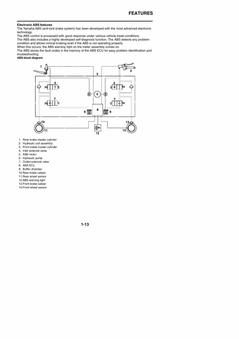
Electronic ABS featuresThe Yamaha ABS (anti-lock brake system) has been developed with the most advanced electronictechnology.The ABS control is processed with good response under various vehicle travel conditions.The ABS also includes a highly developed self-diagnosis function. The ABS detects any problemcondition and allows normal braking even if the ABS is not operating properly.When this occurs, the ABS warning light on the meter assembly comes on.The ABS stores the fault codes in the memory of the ABS ECU for easy problem identification andtroubleshooting.ABS block diagram
1. Rear brake master cylinder
2. Hydraulic unit assembly
3. Front brake master cylinder
4. Inlet solenoid valve
5. ABS motor
6. Hydraulic pump
7. Outlet solenoid valve
8. ABS ECU
ff
8/21/2019 Fz8 - Service Manual
http://slidepdf.com/reader/full/fz8-service-manual 23/609
FEATURES
EAS4B56009
ABS COMPONENT FUNCTIONS
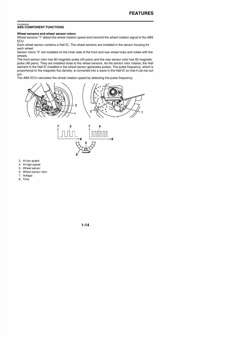
Wheel sensors and wheel sensor rotorsWheel sensors “1” detect the wheel rotation speed and transmit the wheel rotation signal to the ABSECU.Each wheel sensor contains a Hall IC. The wheel sensors are installed in the sensor housing foreach wheel.Sensor rotors “2” are installed on the inner side of the front and rear wheel hubs and rotate with thewheels.
The front sensor rotor has 80 magnetic poles (40 pairs) and the rear sensor rotor has 92 magneticpoles (46 pairs). They are installed close to the wheel sensors. As the sensor rotor rotates, the Hallelement in the Hall IC installed in the wheel sensor generates pulses. The pulse frequency, which isproportional to the magnetic flux density, is converted into a wave in the Hall IC so that it can be out-put.The ABS ECU calculates the wheel rotation speed by detecting the pulse frequency.
3. At low speed
4. At high speed
5 Wheel sensor
8/21/2019 Fz8 - Service Manual
http://slidepdf.com/reader/full/fz8-service-manual 24/609
FEATURES
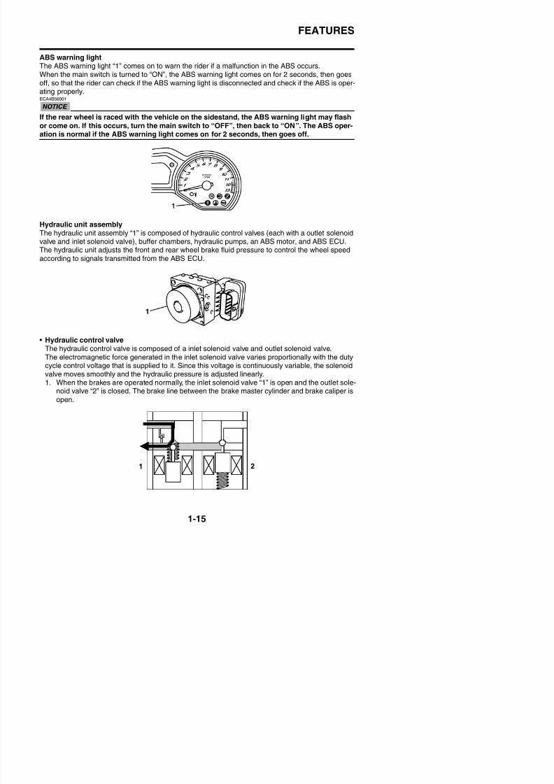
ABS warning lightThe ABS warning light “1” comes on to warn the rider if a malfunction in the ABS occurs.
When the main switch is turned to “ON”, the ABS warning light comes on for 2 seconds, then goesoff, so that the rider can check if the ABS warning light is disconnected and check if the ABS is oper-ating properly.ECA4B56001
If the rear wheel is raced with the vehicle on the sidestand, the ABS warning light may flash
or come on. If this occurs, turn the main switch to “OFF”, then back to “ON”. The ABS oper-ation is normal if the ABS warning light comes on for 2 seconds, then goes off.
Hydraulic unit assemblyThe hydraulic unit assembly “1” is composed of hydraulic control valves (each with a outlet solenoidvalve and inlet solenoid valve), buffer chambers, hydraulic pumps, an ABS motor, and ABS ECU.The hydraulic unit adjusts the front and rear wheel brake fluid pressure to control the wheel speedaccording to signals transmitted from the ABS ECU.
• Hydraulic control valveThe hydraulic control valve is composed of a inlet solenoid valve and outlet solenoid valve.The electromagnetic force generated in the inlet solenoid valve varies proportionally with the dutycycle control voltage that is supplied to it. Since this voltage is continuously variable, the solenoidvalve moves smoothly and the hydraulic pressure is adjusted linearly.1. When the brakes are operated normally, the inlet solenoid valve “1” is open and the outlet sole-
id l “2” i l d Th b k li b h b k li d d b k li i
8/21/2019 Fz8 - Service Manual
http://slidepdf.com/reader/full/fz8-service-manual 25/609
FEATURES
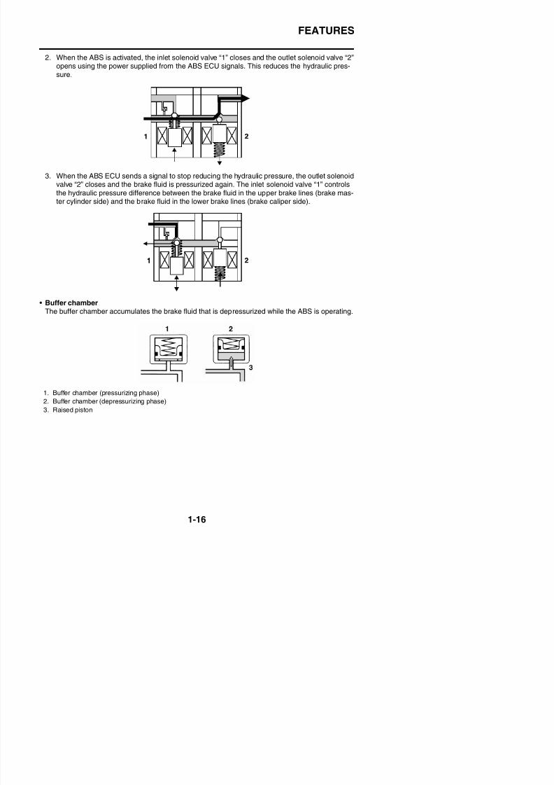
2. When the ABS is activated, the inlet solenoid valve “1” closes and the outlet solenoid valve “2”opens using the power supplied from the ABS ECU signals. This reduces the hydraulic pres-
sure.
3. When the ABS ECU sends a signal to stop reducing the hydraulic pressure, the outlet solenoidvalve “2” closes and the brake fluid is pressurized again. The inlet solenoid valve “1” controlsthe hydraulic pressure difference between the brake fluid in the upper brake lines (brake mas-ter cylinder side) and the brake fluid in the lower brake lines (brake caliper side).
• Buffer chamberThe buffer chamber accumulates the brake fluid that is depressurized while the ABS is operating.
8/21/2019 Fz8 - Service Manual
http://slidepdf.com/reader/full/fz8-service-manual 26/609
FEATURES
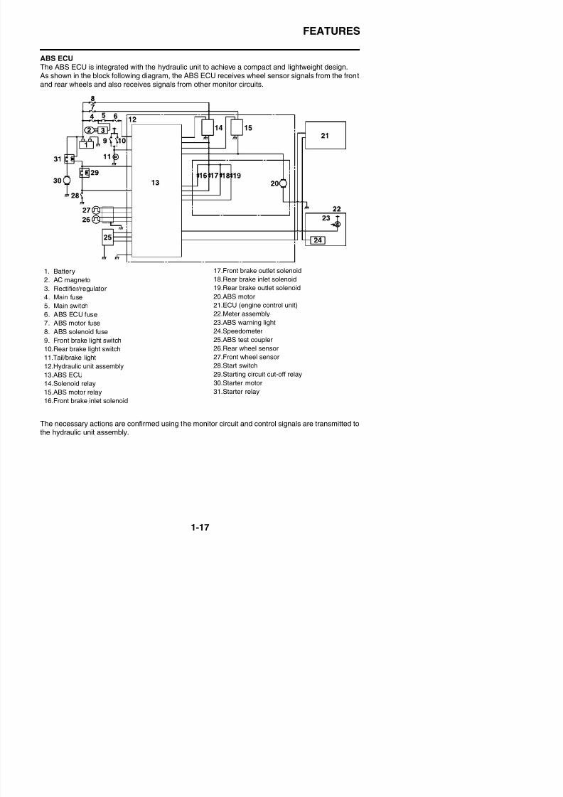
ABS ECUThe ABS ECU is integrated with the hydraulic unit to achieve a compact and lightweight design.
As shown in the block following diagram, the ABS ECU receives wheel sensor signals from the frontand rear wheels and also receives signals from other monitor circuits.
1. Battery
2. AC magneto3. Rectifier/regulator
4. Main fuse
5. Main switch
6. ABS ECU fuse
7. ABS motor fuse
8. ABS solenoid fuse
9. Front brake light switch
10.Rear brake light switch11.Tail/brake light
12.Hydraulic unit assembly
13.ABS ECU
14.Solenoid relay
15.ABS motor relay
17.Front brake outlet solenoid
18.Rear brake inlet solenoid19.Rear brake outlet solenoid
20.ABS motor
21.ECU (engine control unit)
22.Meter assembly
23.ABS warning light
24.Speedometer
25.ABS test coupler
26.Rear wheel sensor27.Front wheel sensor
28.Start switch
29.Starting circuit cut-off relay
30.Starter motor
31.Starter relay
8/21/2019 Fz8 - Service Manual
http://slidepdf.com/reader/full/fz8-service-manual 27/609
FEATURES
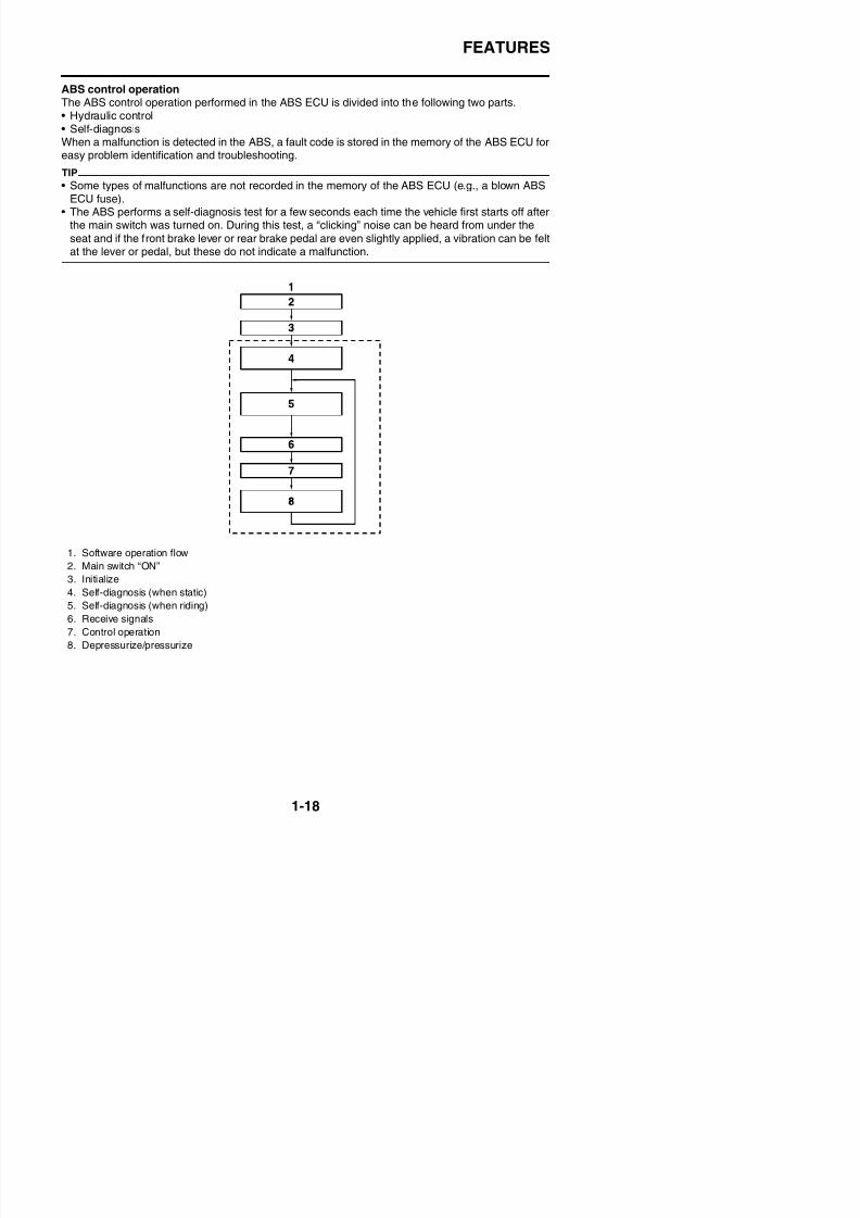
ABS control operationThe ABS control operation performed in the ABS ECU is divided into the following two parts.
• Hydraulic control• Self-diagnosisWhen a malfunction is detected in the ABS, a fault code is stored in the memory of the ABS ECU foreasy problem identification and troubleshooting.
TIP
• Some types of malfunctions are not recorded in the memory of the ABS ECU (e.g., a blown ABSECU fuse).
• The ABS performs a self-diagnosis test for a few seconds each time the vehicle first starts off afterthe main switch was turned on. During this test, a “clicking” noise can be heard from under the
seat and if the front brake lever or rear brake pedal are even slightly applied, a vibration can be feltat the lever or pedal, but these do not indicate a malfunction.
1. Software operation flow
2. Main switch “ON”
3. Initialize
4. Self-diagnosis (when static)
5 Self diagnosis ( hen riding)
8/21/2019 Fz8 - Service Manual
http://slidepdf.com/reader/full/fz8-service-manual 28/609
FEATURES
EAS4B56010
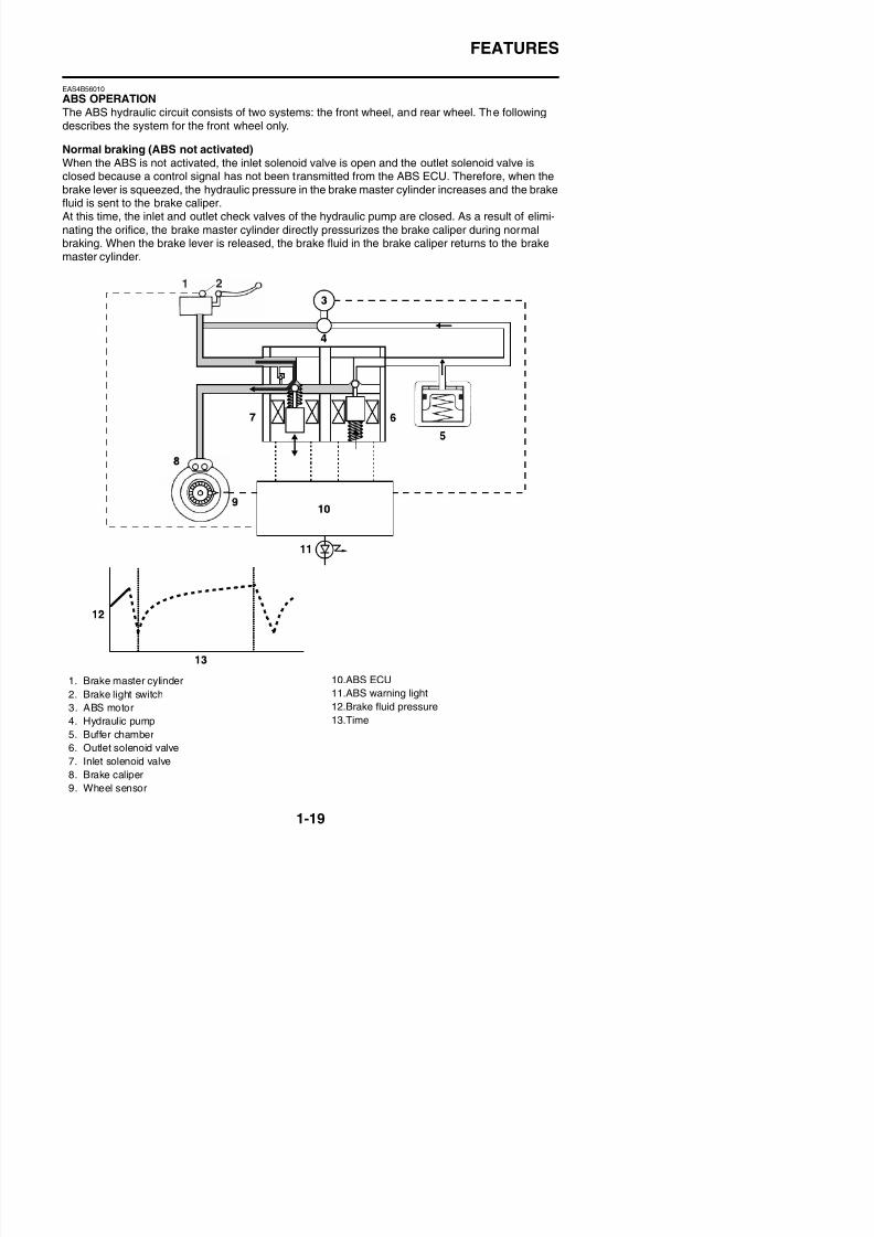
ABS OPERATION
The ABS hydraulic circuit consists of two systems: the front wheel, and rear wheel. The followingdescribes the system for the front wheel only.
Normal braking (ABS not activated)When the ABS is not activated, the inlet solenoid valve is open and the outlet solenoid valve isclosed because a control signal has not been transmitted from the ABS ECU. Therefore, when thebrake lever is squeezed, the hydraulic pressure in the brake master cylinder increases and the brakefluid is sent to the brake caliper.
At this time, the inlet and outlet check valves of the hydraulic pump are closed. As a result of elimi-nating the orifice, the brake master cylinder directly pressurizes the brake caliper during normalbraking. When the brake lever is released, the brake fluid in the brake caliper returns to the brakemaster cylinder.
S
8/21/2019 Fz8 - Service Manual
http://slidepdf.com/reader/full/fz8-service-manual 29/609
FEATURES
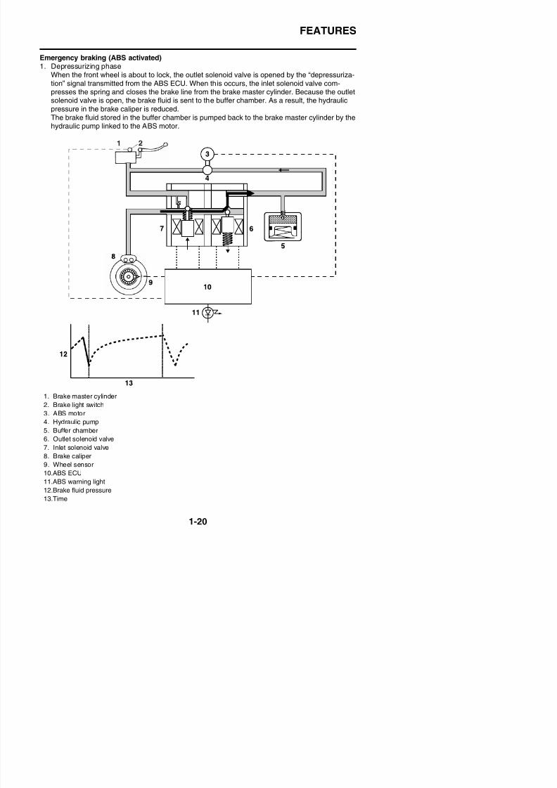
Emergency braking (ABS activated)1. Depressurizing phase
When the front wheel is about to lock, the outlet solenoid valve is opened by the “depressuriza-tion” signal transmitted from the ABS ECU. When this occurs, the inlet solenoid valve com-presses the spring and closes the brake line from the brake master cylinder. Because the outletsolenoid valve is open, the brake fluid is sent to the buffer chamber. As a result, the hydraulicpressure in the brake caliper is reduced.The brake fluid stored in the buffer chamber is pumped back to the brake master cylinder by thehydraulic pump linked to the ABS motor.
FEATURES
8/21/2019 Fz8 - Service Manual
http://slidepdf.com/reader/full/fz8-service-manual 30/609
FEATURES
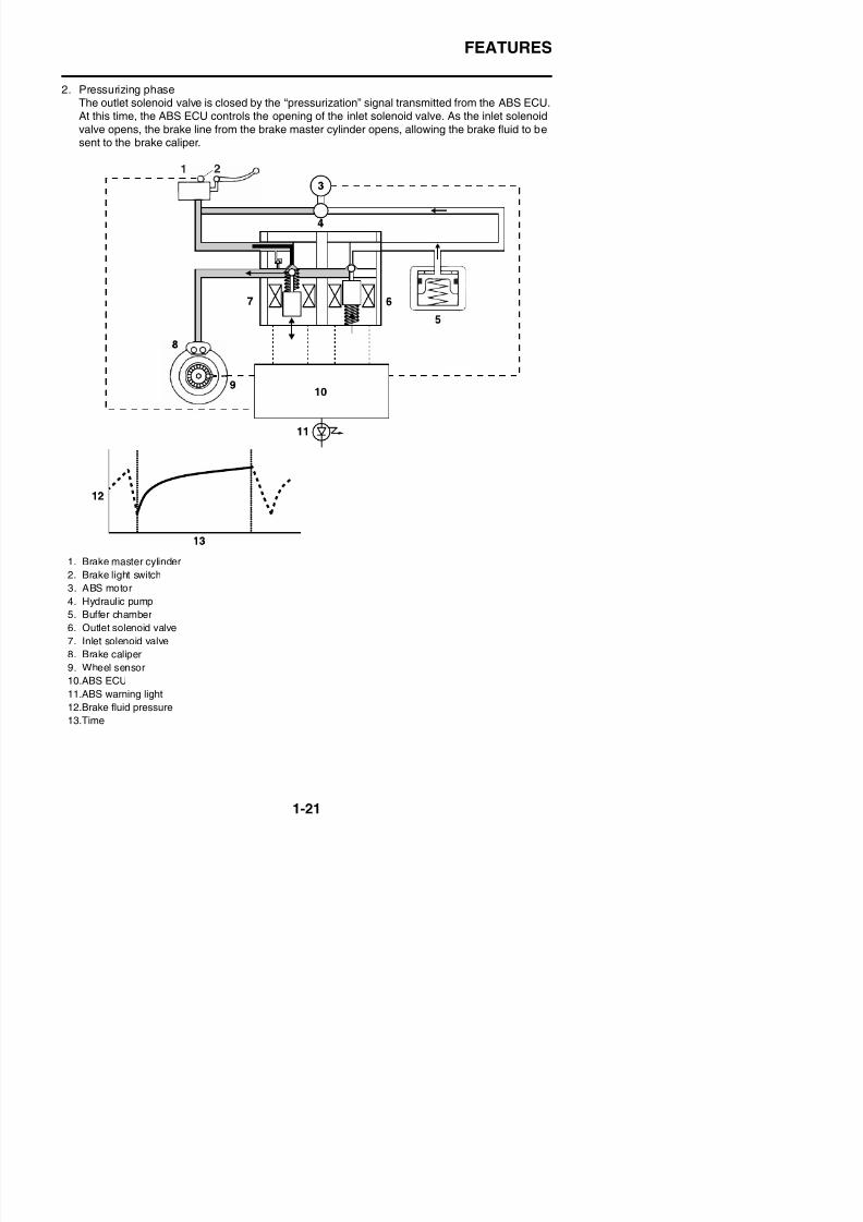
2. Pressurizing phaseThe outlet solenoid valve is closed by the “pressurization” signal transmitted from the ABS ECU.
At this time, the ABS ECU controls the opening of the inlet solenoid valve. As the inlet solenoidvalve opens, the brake line from the brake master cylinder opens, allowing the brake fluid to besent to the brake caliper.
1. Brake master cylinder
2. Brake light switch
3. ABS motor
4. Hydraulic pump
FEATURES
8/21/2019 Fz8 - Service Manual
http://slidepdf.com/reader/full/fz8-service-manual 31/609
FEATURES
EAS4B56011
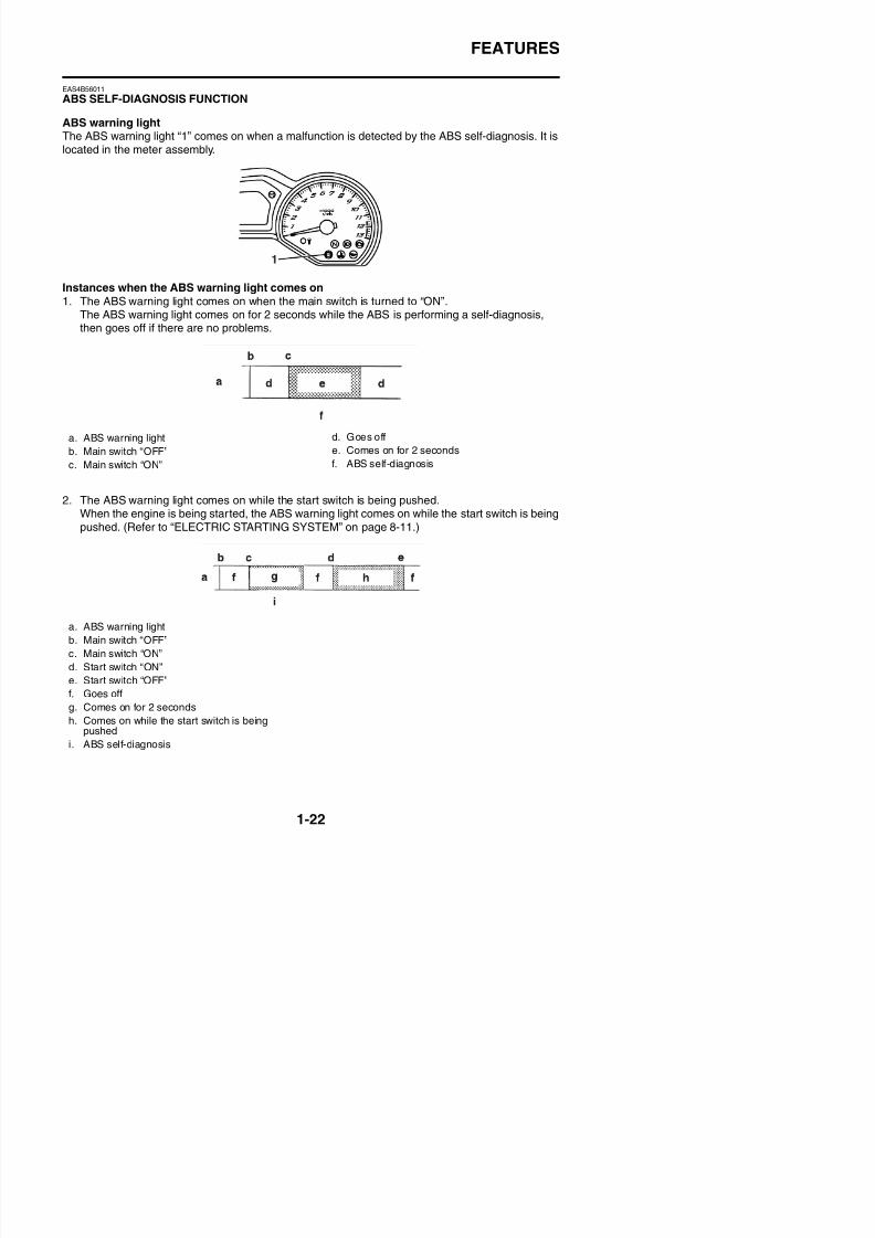
ABS SELF-DIAGNOSIS FUNCTION
ABS warning lightThe ABS warning light “1” comes on when a malfunction is detected by the ABS self-diagnosis. It islocated in the meter assembly.
Instances when the ABS warning light comes on
1. The ABS warning light comes on when the main switch is turned to “ON”.The ABS warning light comes on for 2 seconds while the ABS is performing a self-diagnosis,
then goes off if there are no problems.
2. The ABS warning light comes on while the start switch is being pushed.When the engine is being started, the ABS warning light comes on while the start switch is beingpushed. (Refer to “ELECTRIC STARTING SYSTEM” on page 8-11.)
a. ABS warning lightb. Main switch “OFF”
c. Main switch “ON”
d. Goes offe. Comes on for 2 seconds
f. ABS self-diagnosis
FEATURES
8/21/2019 Fz8 - Service Manual
http://slidepdf.com/reader/full/fz8-service-manual 32/609
FEATURES
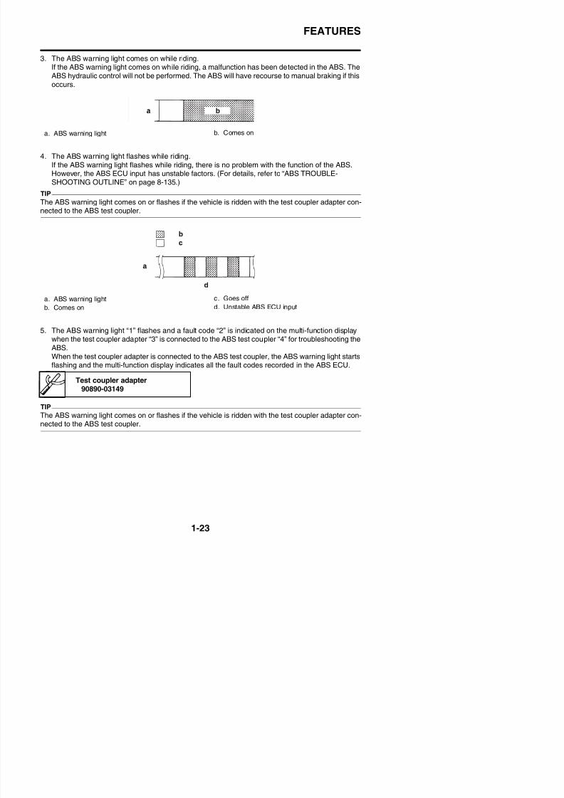
3. The ABS warning light comes on while riding.If the ABS warning light comes on while riding, a malfunction has been detected in the ABS. The
ABS hydraulic control will not be performed. The ABS will have recourse to manual braking if thisoccurs.
4. The ABS warning light flashes while riding.If the ABS warning light flashes while riding, there is no problem with the function of the ABS.However, the ABS ECU input has unstable factors. (For details, refer to “ABS TROUBLE-SHOOTING OUTLINE” on page 8-135.)
TIP
The ABS warning light comes on or flashes if the vehicle is ridden with the test coupler adapter con-
nected to the ABS test coupler.
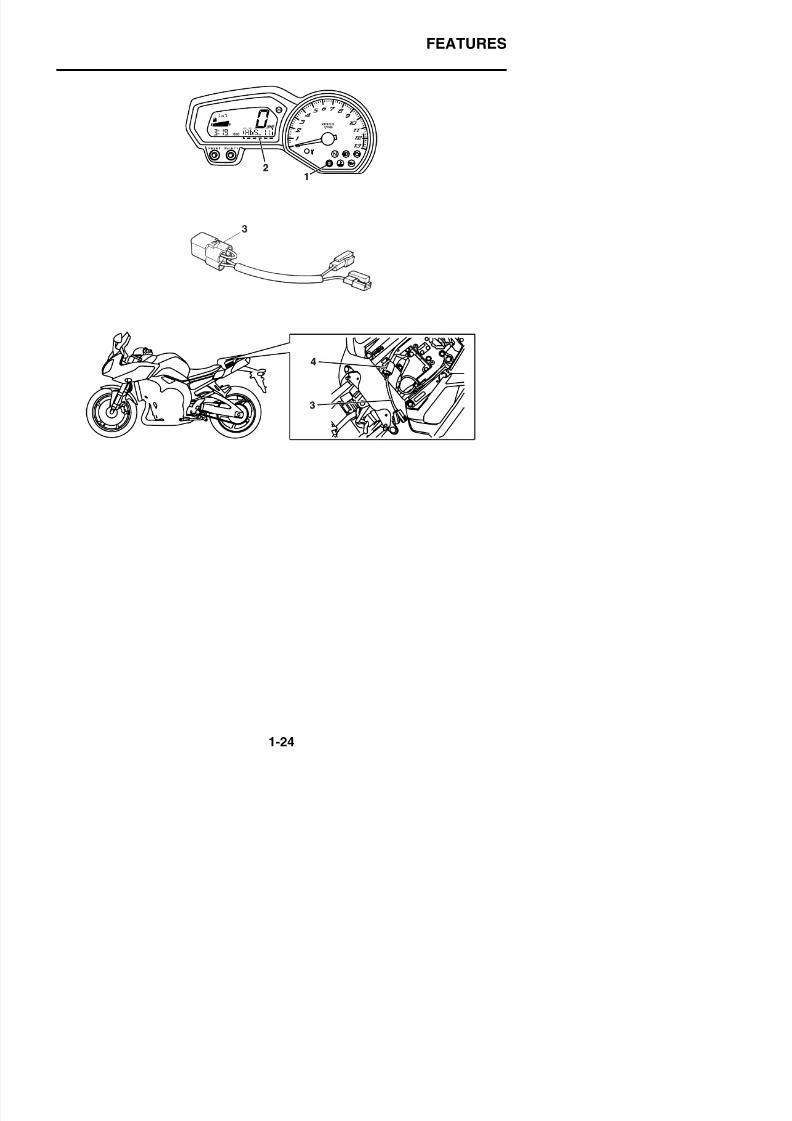
5. The ABS warning light “1” flashes and a fault code “2” is indicated on the multi-function displaywhen the test coupler adapter “3” is connected to the ABS test coupler “4” for troubleshooting theABS.When the test coupler adapter is connected to the ABS test coupler, the ABS warning light startsflashing and the multi-function display indicates all the fault codes recorded in the ABS ECU.
a. ABS warning light b. Comes on
a. ABS warning light
b. Comes on
c. Goes off
d. Unstable ABS ECU input
Test coupler adapter90890-03149
FEATURES
8/21/2019 Fz8 - Service Manual
http://slidepdf.com/reader/full/fz8-service-manual 33/609
FEATURES
FEATURES
8/21/2019 Fz8 - Service Manual
http://slidepdf.com/reader/full/fz8-service-manual 34/609
FEATURES
EAS4B56012
ABS WARNING LIGHT AND OPERATION
ABS warning light• When the main switch is turned to “ON”, the ABS warning light comes on for 2 seconds, then goes
off.• The ABS warning light comes on while the start switch is being pushed.• If the ABS warning light comes on while riding, stop the vehicle, and then turn the main switch to
“OFF”, then back to “ON”. The ABS operation is normal if the ABS warning light comes on for 2seconds, then goes off.
• If the rear wheel is raced with the vehicle on the sidestand, the ABS warning light may flash or
come on. If this occurs, turn the main switch to “OFF”, then back to “ON”. The ABS operation isnormal if the ABS warning light comes on for 2 seconds, then goes off.
• Even if the ABS warning light remains on and does not go off, or if it comes on after riding, conven-tional braking performance of the vehicle is maintained.
ABS function
WARNING
EWA20S1003
• When hydraulic control is performed by the ABS, the brake system alerts the rider that thewheels have a tendency to lock by generating a reaction-force pulsating action in the frontbrake lever or rear brake pedal. When the ABS is activated, the grip between the road sur-face and tires is close to the limit. The ABS cannot prevent wheel lock* on slippery sur-faces, such as ice, when it is caused by engine braking, even if the ABS is activated.
• The ABS is not designed to shorten the braking distance or improve the cornering perfor-mance.
• Depending on the road conditions, the braking distance may be longer compared to that of
vehicles not equipped with ABS. Therefore, ride at a safe speed and keep a safe distancebetween yourself and other vehicles.
• The braking of the vehicle, even in the worst case, is principally executed when the vehicleis advancing straight ahead. During a turn, sudden braking is liable to cause a loss of trac-tion of the tires. Even vehicles equipped with ABS cannot be prevented from falling over ifbraked suddenly.
• The ABS does not work when the main switch is turned to “OFF”. The conventional brakingfunction can be used.
* Wheel lock: A condition that occurs when the rotation of one or both of the wheels hasstopped, but the vehicle continues to travel.
IMPORTANT INFORMATION
8/21/2019 Fz8 - Service Manual
http://slidepdf.com/reader/full/fz8-service-manual 35/609
IMPORTANT INFORMATION
EAS20180
IMPORTANT INFORMATION
EAS20190
PREPARATION FOR REMOVAL AND DISAS-SEMBLY1. Before removal and disassembly, remove
all dirt, mud, dust and foreign material.
2. Use only the proper tools and cleaning
equipment.Refer to “SPECIAL TOOLS” on page 1-33.
3. When disassembling, always keep matedparts together. This includes gears, cylin-ders, pistons and other parts that havebeen “mated” through normal wear. Matedparts must always be reused or replacedas an assembly.
4. During disassembly, clean all of the partsand place them in trays in the order of dis-
assembly. This will speed up assembly andallo for the correct installation of all parts
EAS20210
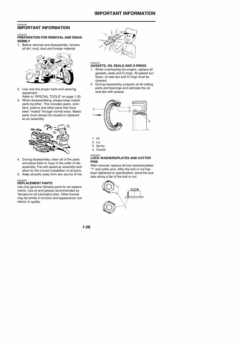
GASKETS, OIL SEALS AND O-RINGS
1. When overhauling the engine, replace allgaskets, seals and O-rings. All gasket sur-faces, oil seal lips and O-rings must becleaned.
2. During reassembly, properly oil all matingparts and bearings and lubricate the oil
seal lips with grease.
EAS20220
LOCK WASHERS/PLATES AND COTTERPINSAfter removal, replace all lock washers/plates“1” and cotter pins. After the bolt or nut has
1. Oil
2. Lip
3. Spring
4. Grease
IMPORTANT INFORMATION
8/21/2019 Fz8 - Service Manual
http://slidepdf.com/reader/full/fz8-service-manual 36/609
IMPORTANT INFORMATION
EAS20231
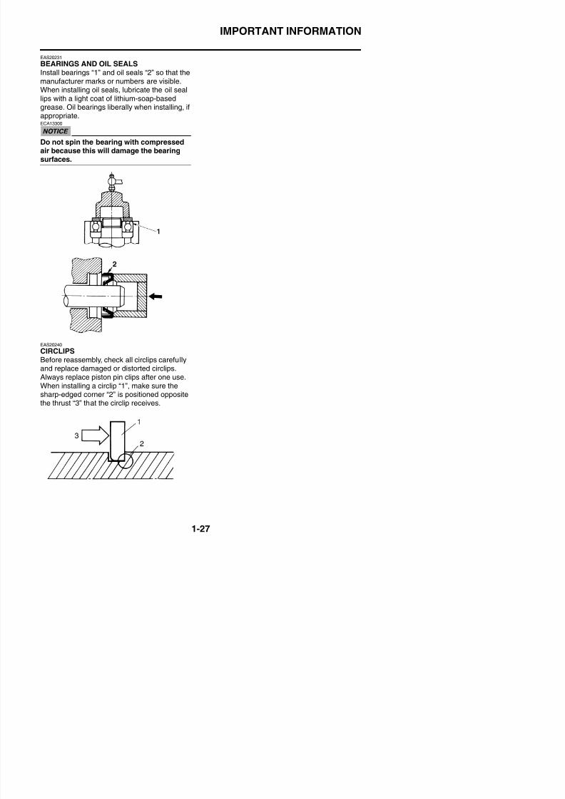
BEARINGS AND OIL SEALS
Install bearings “1” and oil seals “2” so that themanufacturer marks or numbers are visible.When installing oil seals, lubricate the oil seallips with a light coat of lithium-soap-basedgrease. Oil bearings liberally when installing, ifappropriate.ECA13300
Do not spin the bearing with compressedair because this will damage the bearingsurfaces.
EAS20240
CIRCLIPSBefore reassembly, check all circlips carefullyand replace damaged or distorted circlips.Always replace piston pin clips after one use.When installing a circlip “1”, make sure thesharp-edged corner “2” is positioned opposite
BASIC SERVICE INFORMATION
8/21/2019 Fz8 - Service Manual
http://slidepdf.com/reader/full/fz8-service-manual 37/609
EAS30380
BASIC SERVICE INFORMATION
EAS30390
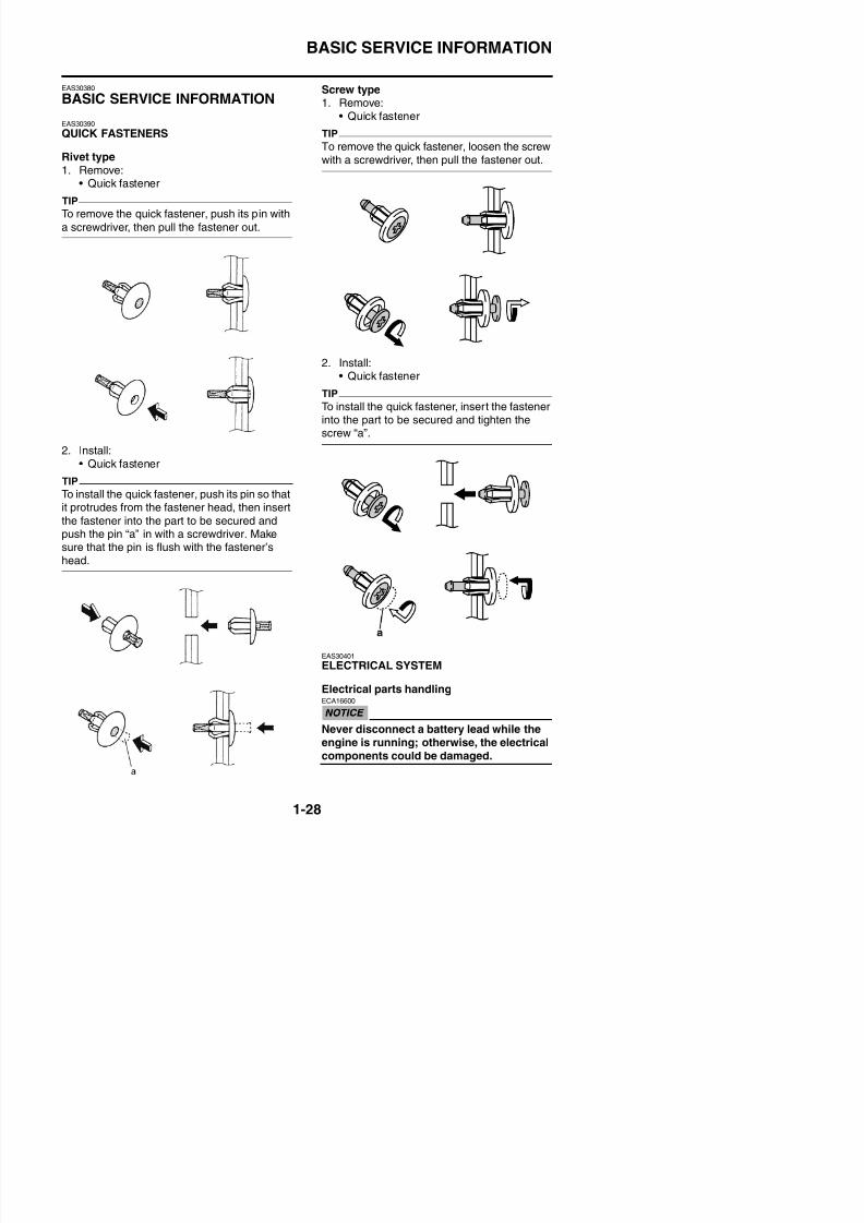
QUICK FASTENERS
Rivet type1. Remove:
• Quick fastener
TIP
To remove the quick fastener, push its pin with
a screwdriver, then pull the fastener out.
2. Install:• Quick fastener
TIP
To install the quick fastener, push its pin so thatit protrudes from the fastener head, then insert
the fastener into the part to be secured andpush the pin “a” in with a screwdriver. Makesure that the pin is flush with the fastener’shead.
Screw type1. Remove:
• Quick fastenerTIP
To remove the quick fastener, loosen the screwwith a screwdriver, then pull the fastener out.
2. Install:• Quick fastener
TIP
To install the quick fastener, insert the fastenerinto the part to be secured and tighten the
screw “a”.
BASIC SERVICE INFORMATION
8/21/2019 Fz8 - Service Manual
http://slidepdf.com/reader/full/fz8-service-manual 38/609
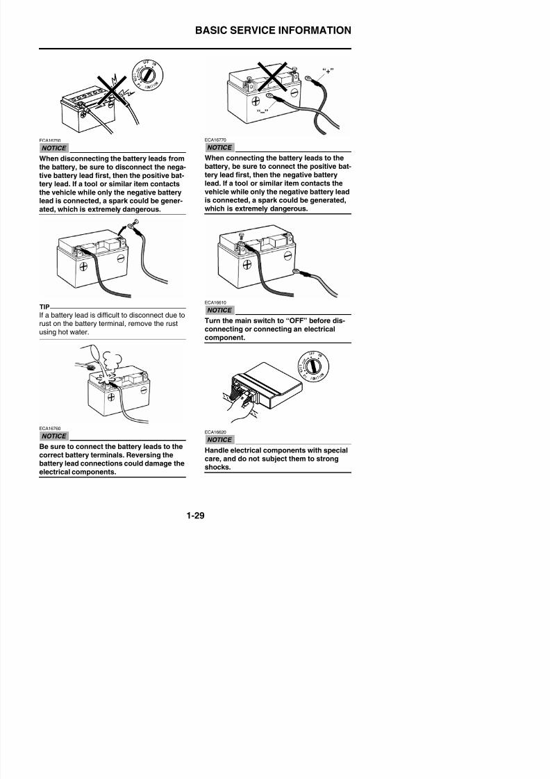
ECA16750
When disconnecting the battery leads fromthe battery, be sure to disconnect the nega-tive battery lead first, then the positive bat-tery lead. If a tool or similar item contactsthe vehicle while only the negative batterylead is connected, a spark could be gener-
ated, which is extremely dangerous.
TIP
If a battery lead is difficult to disconnect due torust on the battery terminal, remove the rustusing hot water.
ECA16770
When connecting the battery leads to thebattery, be sure to connect the positive bat-tery lead first, then the negative batterylead. If a tool or similar item contacts thevehicle while only the negative battery leadis connected, a spark could be generated,
which is extremely dangerous.
ECA16610
Turn the main switch to “OFF” before dis-connecting or connecting an electricalcomponent.
BASIC SERVICE INFORMATION
8/21/2019 Fz8 - Service Manual
http://slidepdf.com/reader/full/fz8-service-manual 39/609
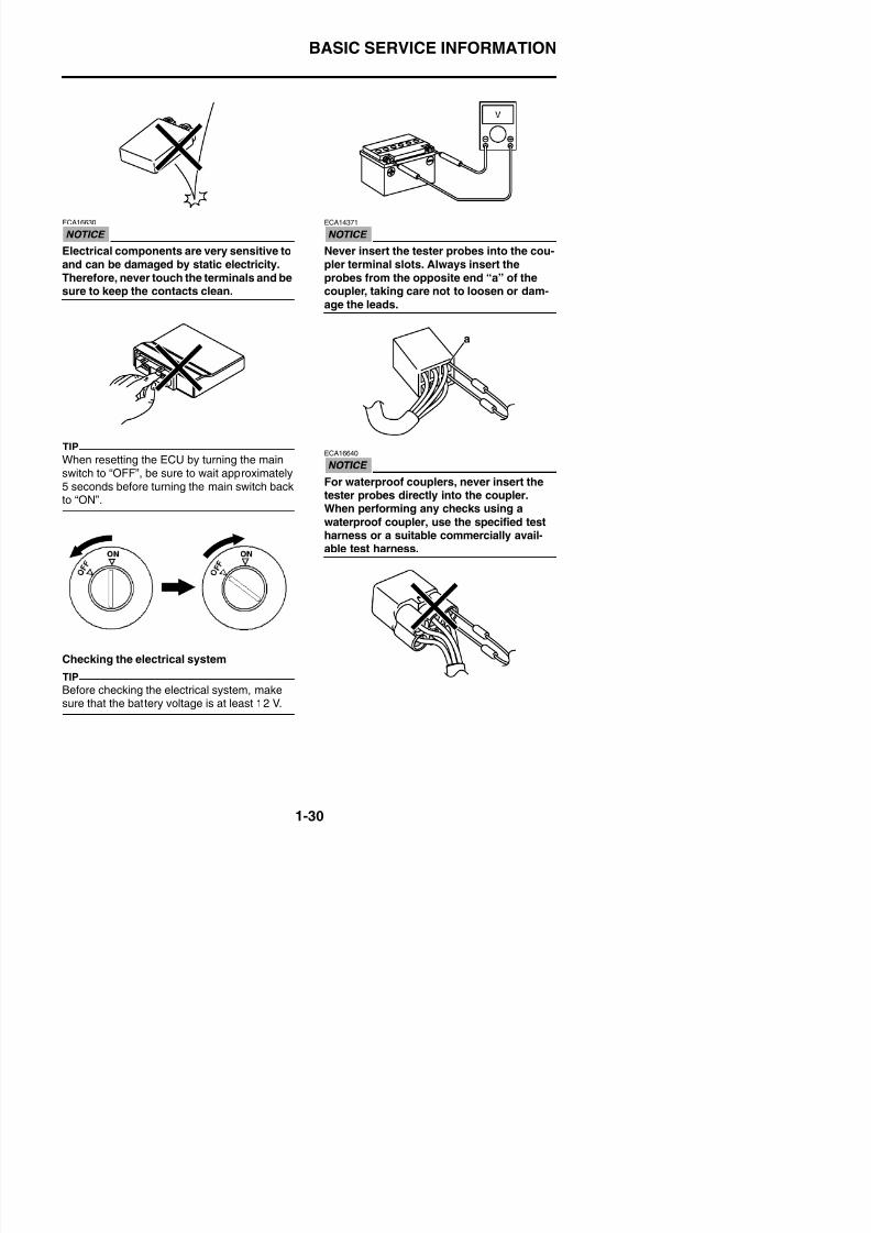
ECA16630
Electrical components are very sensitive toand can be damaged by static electricity.Therefore, never touch the terminals and besure to keep the contacts clean.
TIP
When resetting the ECU by turning the mainswitch to “OFF”, be sure to wait approximately5 seconds before turning the main switch backto “ON”.
ECA14371
Never insert the tester probes into the cou-pler terminal slots. Always insert theprobes from the opposite end “a” of thecoupler, taking care not to loosen or dam-age the leads.
ECA16640
For waterproof couplers, never insert thetester probes directly into the coupler.When performing any checks using a
waterproof coupler, use the specified testharness or a suitable commercially avail-
able test harness.
a
BASIC SERVICE INFORMATION
8/21/2019 Fz8 - Service Manual
http://slidepdf.com/reader/full/fz8-service-manual 40/609
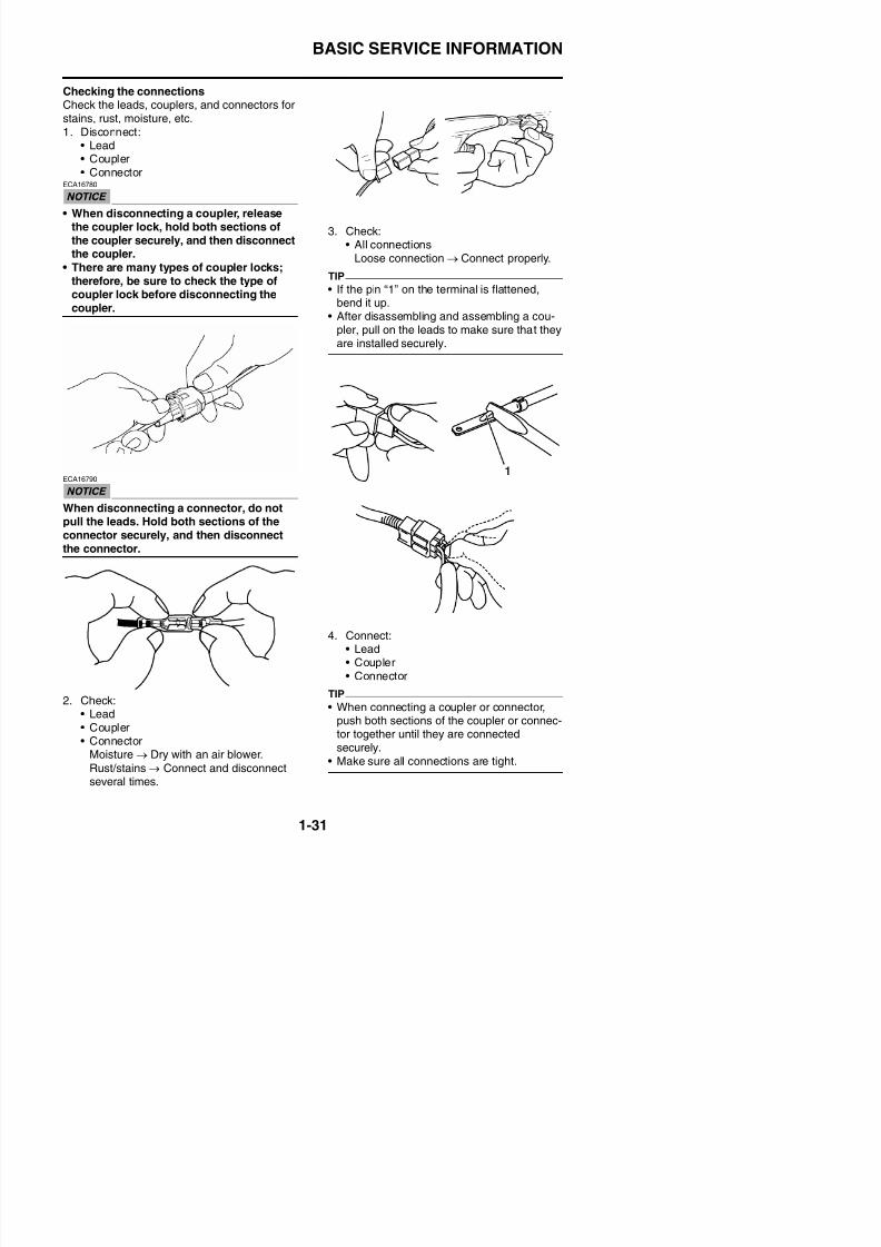
Checking the connectionsCheck the leads, couplers, and connectors for
stains, rust, moisture, etc.1. Disconnect:
• Lead• Coupler• Connector
ECA16780
• When disconnecting a coupler, release
the coupler lock, hold both sections ofthe coupler securely, and then disconnectthe coupler.
• There are many types of coupler locks;therefore, be sure to check the type ofcoupler lock before disconnecting thecoupler.
ECA16790
When disconnecting a connector, do notpull the leads. Hold both sections of theconnector securely, and then disconnect
the connector.
3. Check:• All connections
Loose connection → Connect properly.
TIP
• If the pin “1” on the terminal is flattened,bend it up.
• After disassembling and assembling a cou-
pler, pull on the leads to make sure that theyare installed securely.
1
BASIC SERVICE INFORMATION
8/21/2019 Fz8 - Service Manual
http://slidepdf.com/reader/full/fz8-service-manual 41/609
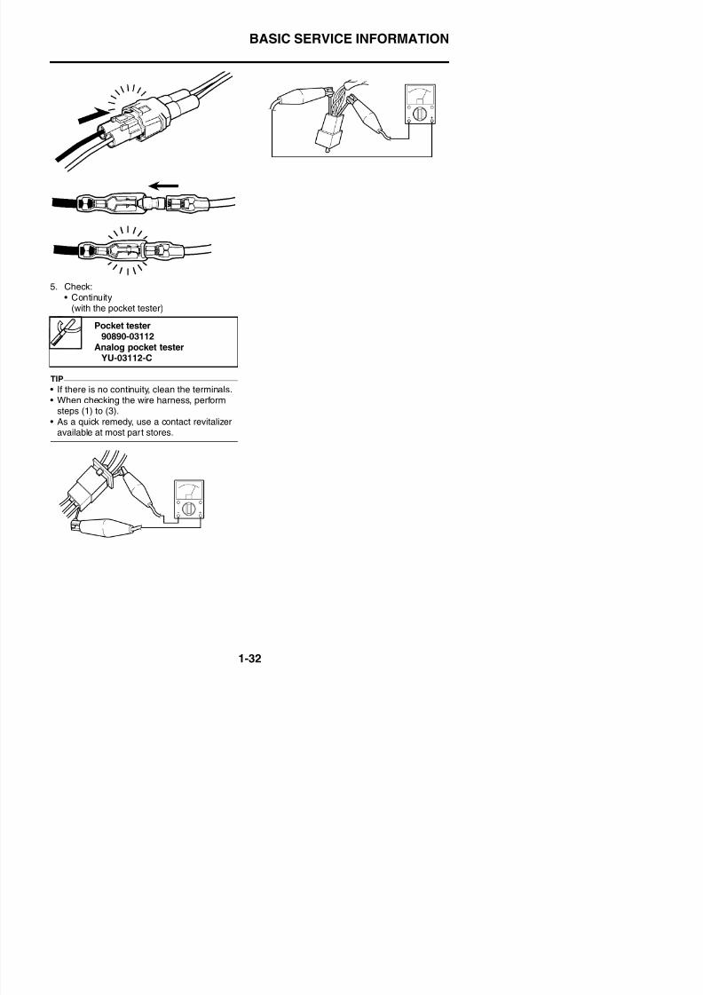
5. Check:• Continuity
(with the pocket tester)
TIP
• If there is no continuity, clean the terminals.• When checking the wire harness, perform
steps (1) to (3).• As a quick remedy, use a contact revitalizer
available at most part stores.
Pocket tester90890-03112
Analog pocket tester
YU-03112-C
SPECIAL TOOLS
8/21/2019 Fz8 - Service Manual
http://slidepdf.com/reader/full/fz8-service-manual 42/609
EAS20260
SPECIAL TOOLS
The following special tools are necessary for complete and accurate tune-up and assembly. Useonly the appropriate special tools as this will help prevent damage caused by the use of inappropri-ate tools or improvised techniques. Special tools, part numbers or both may differ depending on thecountry.When placing an order, refer to the list provided below to avoid any mistakes.
TIP
• For U.S.A. and Canada, use part number starting with “YM-”, “YU-”, or “ACC-”.• For others, use part number starting with “90890-”.
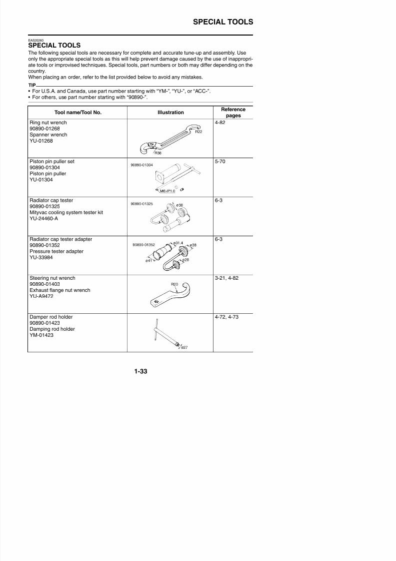
Tool name/Tool No. IllustrationReference
pages
Ring nut wrench90890-01268Spanner wrench
YU-01268
4-82
Piston pin puller set90890-01304Piston pin pullerYU-01304
5-70
Radiator cap tester90890-01325Mityvac cooling system tester kitYU-24460-A
6-3
Radiator cap tester adapter90890-01352Pressure tester adapterYU-33984
6-3
Steering nut wrench 3 21 4 82
SPECIAL TOOLS
8/21/2019 Fz8 - Service Manual
http://slidepdf.com/reader/full/fz8-service-manual 43/609
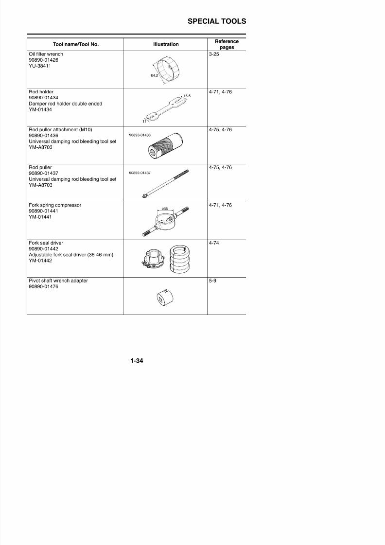
Oil filter wrench90890-01426YU-38411
3-25
Rod holder
90890-01434Damper rod holder double endedYM-01434
4-71, 4-76
Rod puller attachment (M10)90890-01436Universal damping rod bleeding tool set
YM-A8703
4-75, 4-76
Rod puller90890-01437Universal damping rod bleeding tool setYM-A8703
4-75, 4-76
Fork spring compressor90890-01441
YM-01441
4-71, 4-76
Fork seal driver90890-01442Adjustable fork seal driver (36-46 mm)YM-01442
4-74
Tool name/Tool No. IllustrationReference
pages
SPECIAL TOOLS
8/21/2019 Fz8 - Service Manual
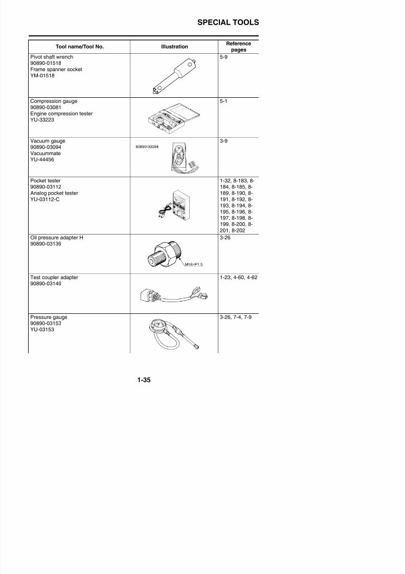
http://slidepdf.com/reader/full/fz8-service-manual 44/609
Pivot shaft wrench90890-01518Frame spanner socketYM-01518
5-9
Compression gauge90890-03081Engine compression testerYU-33223
5-1
Vacuum gauge90890-03094
VacuummateYU-44456
3-9
Pocket tester90890-03112Analog pocket testerYU-03112-C
1-32, 8-183, 8-184, 8-185, 8-189, 8-190, 8-191, 8-192, 8-
193, 8-194, 8-195, 8-196, 8-197, 8-198, 8-199, 8-200, 8-
201, 8-202
Oil pressure adapter H90890-03139
3-26
Test coupler adapter90890-03149
1-23, 4-60, 4-62
Tool name/Tool No. IllustrationReference
pages
SPECIAL TOOLS
8/21/2019 Fz8 - Service Manual
http://slidepdf.com/reader/full/fz8-service-manual 45/609
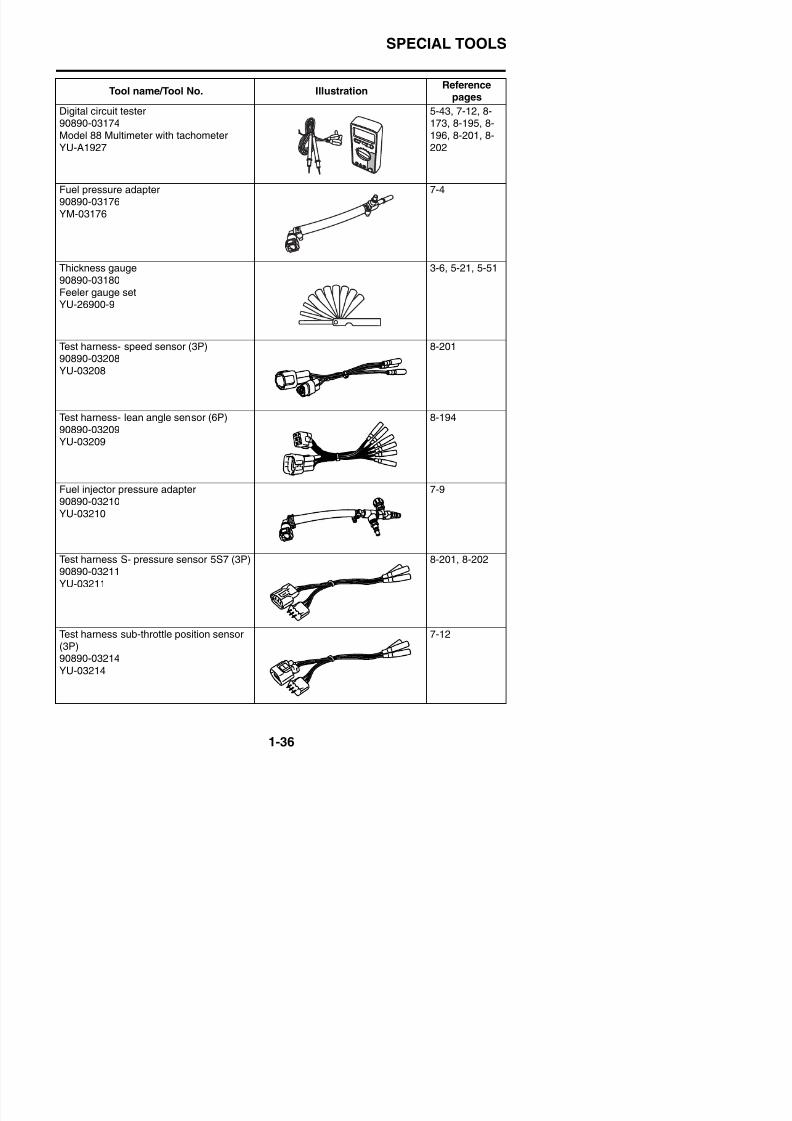
Digital circuit tester90890-03174Model 88 Multimeter with tachometerYU-A1927
5-43, 7-12, 8-173, 8-195, 8-196, 8-201, 8-202
Fuel pressure adapter
90890-03176YM-03176
7-4
Thickness gauge90890-03180Feeler gauge set
YU-26900-9
3-6, 5-21, 5-51
Test harness- speed sensor (3P)90890-03208YU-03208
8-201
Test harness- lean angle sensor (6P)90890-03209YU-03209
8-194
Fuel injector pressure adapter
90890-03210YU-03210
7-9
S S ( )
Tool name/Tool No. IllustrationReference
pages
SPECIAL TOOLS
8/21/2019 Fz8 - Service Manual
http://slidepdf.com/reader/full/fz8-service-manual 46/609
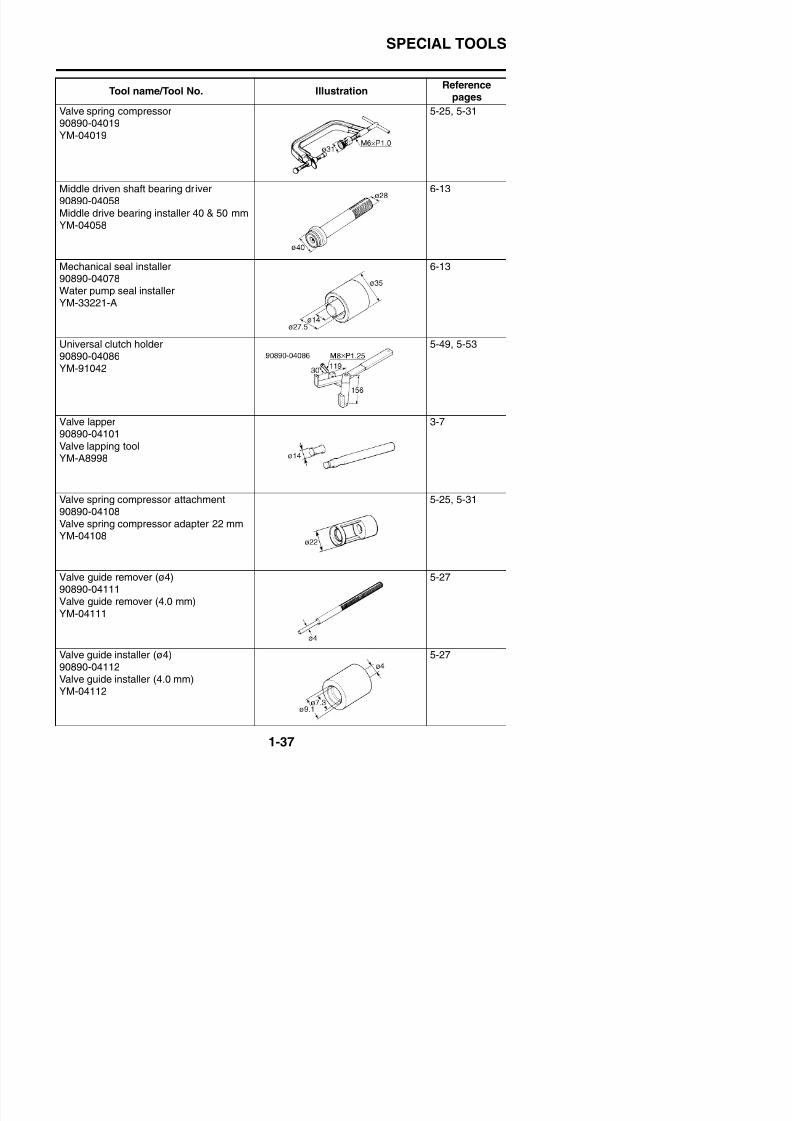
Valve spring compressor90890-04019YM-04019
5-25, 5-31
Middle driven shaft bearing driver
90890-04058Middle drive bearing installer 40 & 50 mmYM-04058
6-13
Mechanical seal installer90890-04078Water pump seal installer
YM-33221-A
6-13
Universal clutch holder90890-04086YM-91042
5-49, 5-53
Valve lapper90890-04101
Valve lapping toolYM-A8998
3-7
Valve spring compressor attachment90890-04108Valve spring compressor adapter 22 mmYM-04108
5-25, 5-31
Tool name/Tool No. IllustrationReference
pages
SPECIAL TOOLS
8/21/2019 Fz8 - Service Manual
http://slidepdf.com/reader/full/fz8-service-manual 47/609
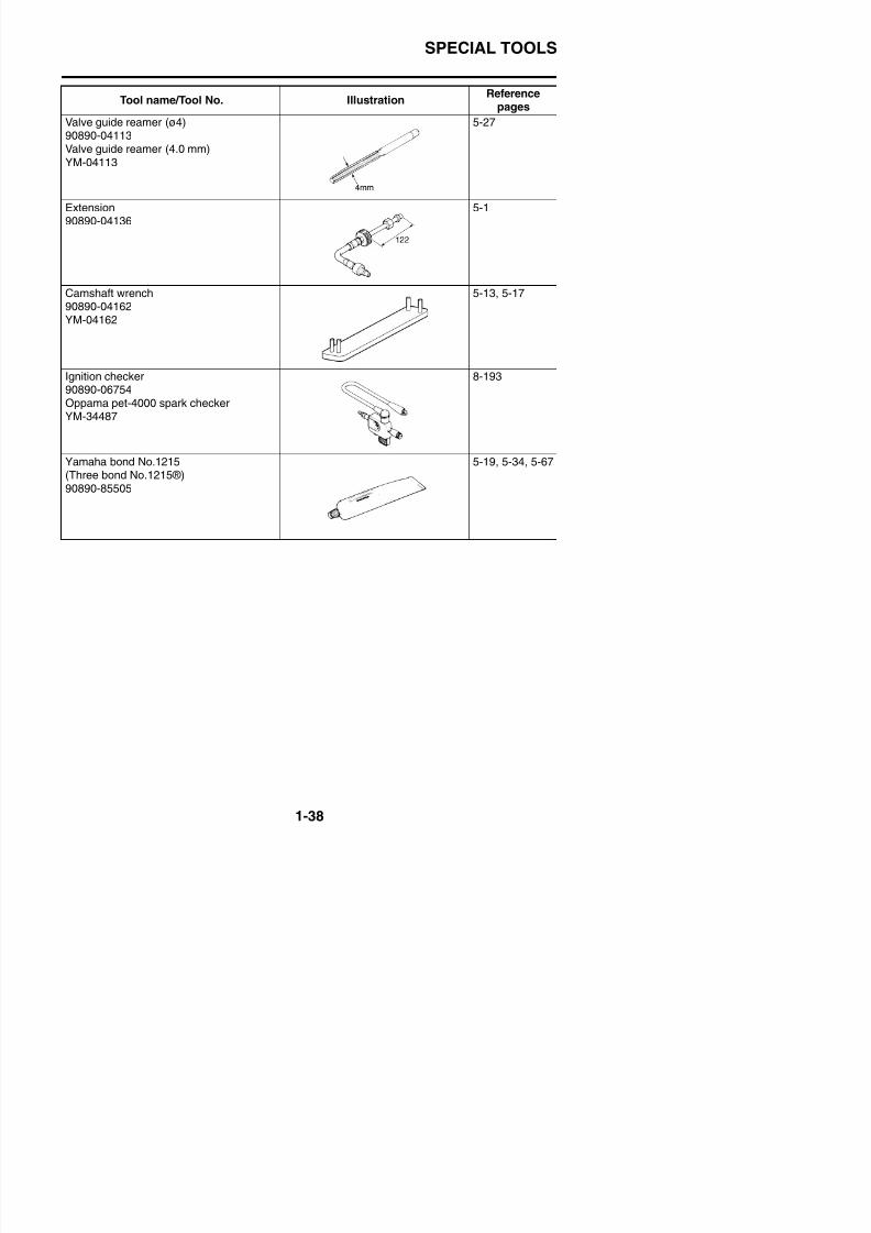
Valve guide reamer (ø4)90890-04113Valve guide reamer (4.0 mm)YM-04113
5-27
Extension
90890-04136
5-1
Camshaft wrench90890-04162YM-04162
5-13, 5-17
Ignition checker90890-06754Oppama pet-4000 spark checkerYM-34487
8-193
Yamaha bond No.1215(Three bond No.1215®)90890-85505
5-19, 5-34, 5-67
Tool name/Tool No. IllustrationReference
pages
SPECIAL TOOLS

8/21/2019 Fz8 - Service Manual
http://slidepdf.com/reader/full/fz8-service-manual 48/609
8/21/2019 Fz8 - Service Manual
http://slidepdf.com/reader/full/fz8-service-manual 49/609
2
SPECIFICATIONS
GENERAL SPECIFICATIONS ......................................................................2-1
ENGINE SPECIFICATIONS..........................................................................2-2
CHASSIS SPECIFICATIONS........................................................................2-9
ELECTRICAL SPECIFICATIONS...............................................................2-12
TIGHTENING TORQUES............................................................................2-14GENERAL TIGHTENING TORQUE SPECIFICATIONS.......................2-14ENGINE TIGHTENING TORQUES ......................................................2-15CHASSIS TIGHTENING TORQUES ....................................................2-19
LUBRICATION POINTS AND LUBRICANT TYPES ..................................2-23ENGINE ................................................................................................2-23CHASSIS ..............................................................................................2-25
LUBRICATION SYSTEM CHART AND DIAGRAMS .................................2-27ENGINE OIL LUBRICATION CHART ...................................................2-27LUBRICATION DIAGRAMS.................................................................. 2-29
COOLING SYSTEM DIAGRAMS ...............................................................2-39
CABLE ROUTING ......................................................................................2-43
GENERAL SPECIFICATIONS
8/21/2019 Fz8 - Service Manual
http://slidepdf.com/reader/full/fz8-service-manual 50/609
EAS20280
GENERAL SPECIFICATIONS
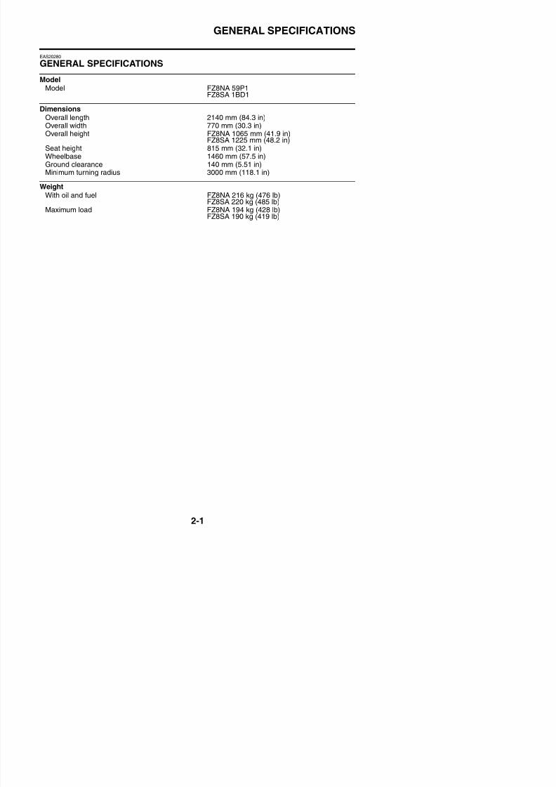
ModelModel FZ8NA 59P1
FZ8SA 1BD1
DimensionsOverall length 2140 mm (84.3 in)Overall width 770 mm (30.3 in)Overall height FZ8NA 1065 mm (41.9 in)
FZ8SA 1225 mm (48.2 in)Seat height 815 mm (32.1 in)Wheelbase 1460 mm (57.5 in)Ground clearance 140 mm (5.51 in)Minimum turning radius 3000 mm (118.1 in)
WeightWith oil and fuel FZ8NA 216 kg (476 lb)
FZ8SA 220 kg (485 lb)
Maximum load FZ8NA 194 kg (428 lb)FZ8SA 190 kg (419 lb)
ENGINE SPECIFICATIONS
8/21/2019 Fz8 - Service Manual
http://slidepdf.com/reader/full/fz8-service-manual 51/609
EAS20290
ENGINE SPECIFICATIONS
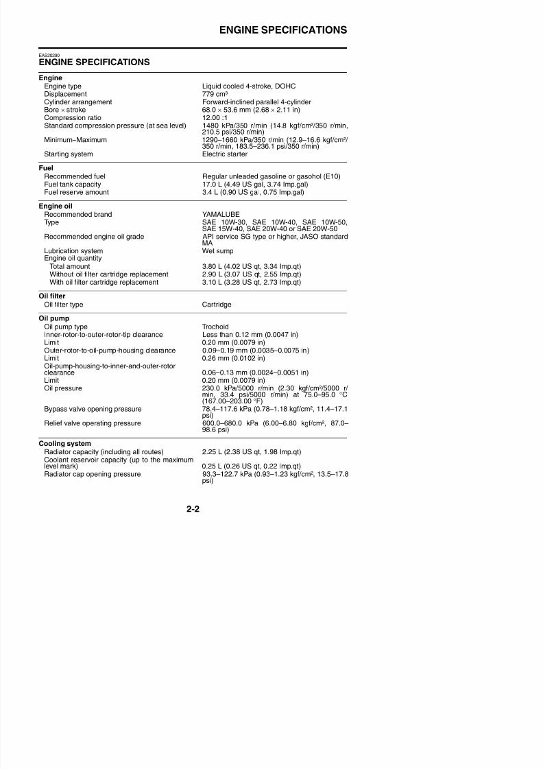
EngineEngine type Liquid cooled 4-stroke, DOHCDisplacement 779 cm³Cylinder arrangement Forward-inclined parallel 4-cylinderBore × stroke 68.0 × 53.6 mm (2.68 × 2.11 in)Compression ratio 12.00 :1Standard compression pressure (at sea level) 1480 kPa/350 r/min (14.8 kgf/cm²/350 r/min,
210.5 psi/350 r/min)
Minimum–Maximum 1290–1660 kPa/350 r/min (12.9–16.6 kgf/cm²/ 350 r/min, 183.5–236.1 psi/350 r/min)Starting system Electric starter
FuelRecommended fuel Regular unleaded gasoline or gasohol (E10)Fuel tank capacity 17.0 L (4.49 US gal, 3.74 Imp.gal)Fuel reserve amount 3.4 L (0.90 US gal, 0.75 Imp.gal)
Engine oilRecommended brand YAMALUBEType SAE 10W-30, SAE 10W-40, SAE 10W-50,
SAE 15W-40, SAE 20W-40 or SAE 20W-50Recommended engine oil grade API service SG type or higher, JASO standard
MALubrication system Wet sumpEngine oil quantity
Total amount 3.80 L (4.02 US qt, 3.34 Imp.qt)
Without oil filter cartridge replacement 2.90 L (3.07 US qt, 2.55 Imp.qt)With oil filter cartridge replacement 3.10 L (3.28 US qt, 2.73 Imp.qt)
Oil filter
Oil filter type Cartridge
Oil pumpOil pump type TrochoidInner-rotor-to-outer-rotor-tip clearance Less than 0.12 mm (0.0047 in)
Limit 0.20 mm (0.0079 in)Outer-rotor-to-oil-pump-housing clearance 0.09–0.19 mm (0.0035–0.0075 in)Limit 0.26 mm (0.0102 in)Oil-pump-housing-to-inner-and-outer-rotorclearance 0.06–0.13 mm (0.0024–0.0051 in)Limit 0 20 mm (0 0079 in)
ENGINE SPECIFICATIONS
8/21/2019 Fz8 - Service Manual
http://slidepdf.com/reader/full/fz8-service-manual 52/609
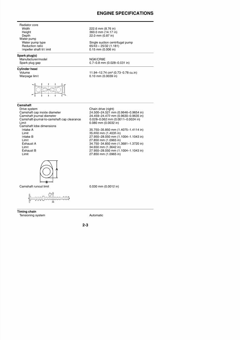
Radiator coreWidth 222.6 mm (8.76 in)
Height 360.0 mm (14.17 in)Depth 22.0 mm (0.87 in)Water pump
Water pump type Single suction centrifugal pumpReduction ratio 65/43 × 25/32 (1.181)Impeller shaft tilt limit 0.15 mm (0.006 in)
Spark plug(s)Manufacturer/model NGK/CR9E
Spark plug gap 0.7–0.8 mm (0.028–0.031 in)
Cylinder headVolume 11.94–12.74 cm³ (0.73–0.78 cu.in)Warpage limit 0.10 mm (0.0039 in)
CamshaftDrive system Chain drive (right)Camshaft cap inside diameter 24.500–24.521 mm (0.9646–0.9654 in)Camshaft journal diameter 24.459–24.472 mm (0.9630–0.9635 in)Camshaft-journal-to-camshaft cap clearance 0.028–0.062 mm (0.0011–0.0024 in)
Limit 0.080 mm (0.0032 in)Camshaft lobe dimensions
Intake A 35.750–35.850 mm (1.4075–1.4114 in)Limit 35.650 mm (1.4035 in)Intake B 27.950–28.050 mm (1.1004–1.1043 in)Limit 27.850 mm (1.0965 in)Exhaust A 34.750–34.850 mm (1.3681–1.3720 in)Limit 34.650 mm (1.3642 in)
Exhaust B 27.950–28.050 mm (1.1004–1.1043 in)Limit 27.850 mm (1.0965 in)
ENGINE SPECIFICATIONS
8/21/2019 Fz8 - Service Manual
http://slidepdf.com/reader/full/fz8-service-manual 53/609
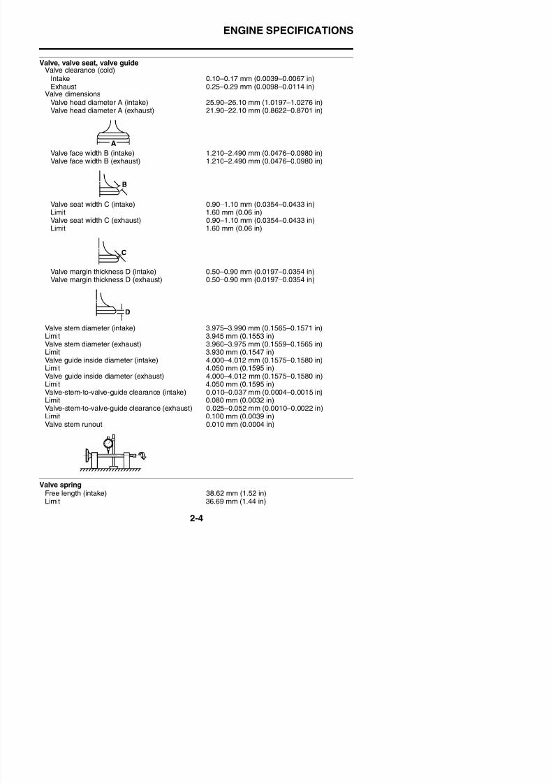
Valve, valve seat, valve guideValve clearance (cold)
Intake 0.10–0.17 mm (0.0039–0.0067 in)Exhaust 0.25–0.29 mm (0.0098–0.0114 in)
Valve dimensionsValve head diameter A (intake) 25.90–26.10 mm (1.0197–1.0276 in)Valve head diameter A (exhaust) 21.90–22.10 mm (0.8622–0.8701 in)
Valve face width B (intake) 1.210–2.490 mm (0.0476–0.0980 in)Valve face width B (exhaust) 1.210–2.490 mm (0.0476–0.0980 in)
Valve seat width C (intake) 0.90–1.10 mm (0.0354–0.0433 in)
Limit 1.60 mm (0.06 in)Valve seat width C (exhaust) 0.90–1.10 mm (0.0354–0.0433 in)Limit 1.60 mm (0.06 in)
Valve margin thickness D (intake) 0.50–0.90 mm (0.0197–0.0354 in)
Valve margin thickness D (exhaust) 0.50–0.90 mm (0.0197–0.0354 in)
Valve stem diameter (intake) 3.975–3.990 mm (0.1565–0.1571 in)Limit 3.945 mm (0.1553 in)Valve stem diameter (exhaust) 3.960–3.975 mm (0.1559–0.1565 in)Limit 3.930 mm (0.1547 in)Valve guide inside diameter (intake) 4.000–4.012 mm (0.1575–0.1580 in)Limit 4.050 mm (0.1595 in)Valve guide inside diameter (exhaust) 4.000–4.012 mm (0.1575–0.1580 in)Limit 4.050 mm (0.1595 in)
ENGINE SPECIFICATIONS
8/21/2019 Fz8 - Service Manual
http://slidepdf.com/reader/full/fz8-service-manual 54/609
Free length (exhaust) 38.62 mm (1.52 in)Limit 36.69 mm (1.44 in)
Installed length (intake) 33.00 mm (1.30 in)Installed length (exhaust) 33.00 mm (1.30 in)Spring rate K1 (intake) 24.99 N/mm (2.55 kgf/mm, 142.69 lb/in)Spring rate K2 (intake) 37.28 N/mm (3.80 kgf/mm, 212.87 lb/in)Spring rate K1 (exhaust) 24.99 N/mm (2.55 kgf/mm, 142.69 lb/in)Spring rate K2 (exhaust) 37.28 N/mm (3.80 kgf/mm, 212.87 lb/in)Installed compression spring force (intake) 130.60–150.20 N (13.32–15.32 kgf, 29.36–
33.76 lbf)Installed compression spring force (exhaust) 130.60–150.20 N (13.32–15.32 kgf, 29.36–
33.76 lbf)Spring tilt (intake) 2.5° /1.7 mm (0.067 in)Spring tilt (exhaust) 2.5° /1.7 mm (0.067 in)
Winding direction (intake) ClockwiseWinding direction (exhaust) Clockwise
CylinderBore 68.000–68.010 mm (2.6772–2.6776 in)Taper limit 0.050 mm (0.0020 in)Out of round limit 0.050 mm (0.0020 in)
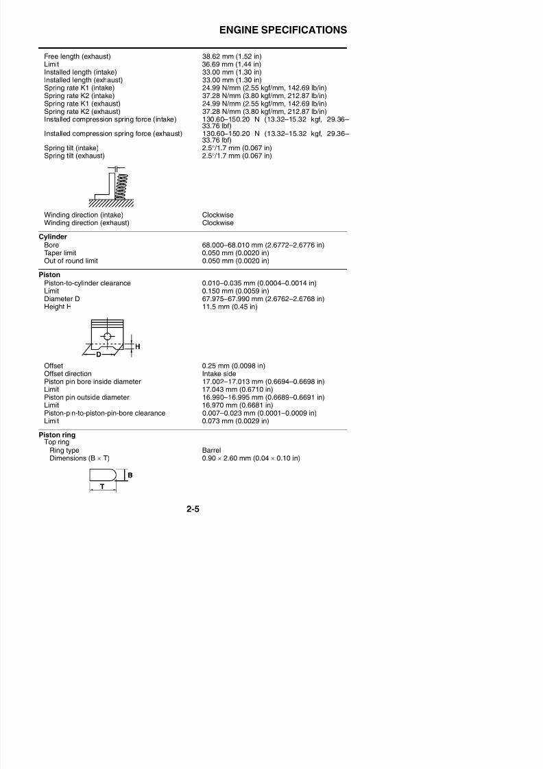
PistonPiston-to-cylinder clearance 0.010–0.035 mm (0.0004–0.0014 in)Limit 0.150 mm (0.0059 in)Diameter D 67.975–67.990 mm (2.6762–2.6768 in)Height H 11.5 mm (0.45 in)
Offset 0.25 mm (0.0098 in)Offset direction Intake sidePiston pin bore inside diameter 17 002 17 013 mm (0 6694 0 6698 in)
ENGINE SPECIFICATIONS
8/21/2019 Fz8 - Service Manual
http://slidepdf.com/reader/full/fz8-service-manual 55/609
End gap (installed) 0.25–0.35 mm (0.0098–0.0138 in)Limit 0.60 mm (0.0236 in)
Ring side clearance 0.030–0.065 mm (0.0012–0.0026 in)Limit 0.115 mm (0.0045 in)2nd ring
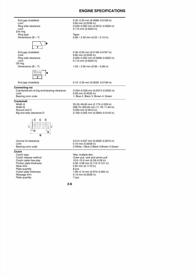
Ring type TaperDimensions (B × T) 0.80 × 2.50 mm (0.03 × 0.10 in)
End gap (installed) 0.35–0.50 mm (0.0138–0.0197 in)Limit 0.85 mm (0.0335 in)Ring side clearance 0.020–0.055 mm (0.0008–0.0022 in)Limit 0.115 mm (0.0045 in)
Oil ringDimensions (B × T) 1.50 × 2.00 mm (0.06 × 0.08 in)
End gap (installed) 0.10–0.35 mm (0.0039–0.0138 in)
Connecting rodCrankshaft-pin-to-big-end-bearing clearance 0.034–0.058 mm (0.0013–0.0023 in)Limit 0.09 mm (0.0035 in)Bearing color code 1: Blue 2: Black 3: Brown 4: Green
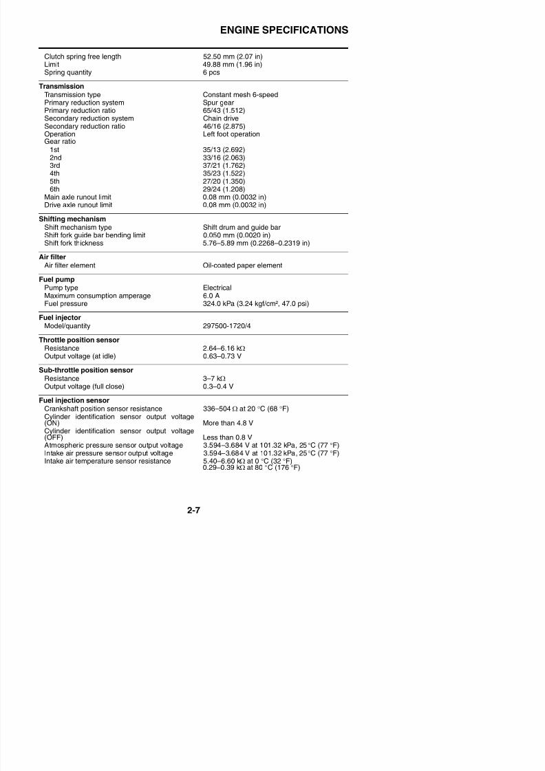
CrankshaftWidth A 55.20–56.60 mm (2.173–2.228 in)Width B 298.75–300.65 mm (11.76–11.84 in)Runout limit C 0.030 mm (0.0012 in)Big end side clearance D 0.160–0.262 mm (0.0063–0.0103 in)
ENGINE SPECIFICATIONS
8/21/2019 Fz8 - Service Manual
http://slidepdf.com/reader/full/fz8-service-manual 56/609
Clutch spring free length 52.50 mm (2.07 in)Limit 49.88 mm (1.96 in)
Spring quantity 6 pcs
TransmissionTransmission type Constant mesh 6-speedPrimary reduction system Spur gearPrimary reduction ratio 65/43 (1.512)Secondary reduction system Chain driveSecondary reduction ratio 46/16 (2.875)Operation Left foot operation
Gear ratio1st 35/13 (2.692)2nd 33/16 (2.063)3rd 37/21 (1.762)4th 35/23 (1.522)5th 27/20 (1.350)6th 29/24 (1.208)
Main axle runout limit 0.08 mm (0.0032 in)Drive axle runout limit 0.08 mm (0.0032 in)
Shifting mechanismShift mechanism type Shift drum and guide barShift fork guide bar bending limit 0.050 mm (0.0020 in)Shift fork thickness 5.76–5.89 mm (0.2268–0.2319 in)
Air filterAir filter element Oil-coated paper element
Fuel pumpPump type ElectricalMaximum consumption amperage 6.0 AFuel pressure 324.0 kPa (3.24 kgf/cm², 47.0 psi)
Fuel injectorModel/quantity 297500-1720/4
Throttle position sensorResistance 2.64–6.16 kΩOutput voltage (at idle) 0.63–0.73 V
Sub-throttle position sensorResistance 3–7 kΩ
ENGINE SPECIFICATIONS
8/21/2019 Fz8 - Service Manual
http://slidepdf.com/reader/full/fz8-service-manual 57/609
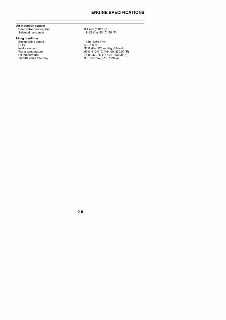
Air induction systemReed valve bending limit 0.4 mm (0.016 in)
Solenoid resistance 18–22 Ω at 20 °C (68 °F)
Idling conditionEngine idling speed 1150–1250 r/minCO% 4.0–5.0 %Intake vacuum 30.0 kPa (225 mmHg, 8.9 inHg)Water temperature 90.0–110.0 °C (194.00–230.00 °F)Oil temperature 75.0–95.0 °C (167.00–203.00 °F)
Throttle cable free play 3.0–5.0 mm (0.12–0.20 in)
CHASSIS SPECIFICATIONS
EAS20300
8/21/2019 Fz8 - Service Manual
http://slidepdf.com/reader/full/fz8-service-manual 58/609
EAS20300
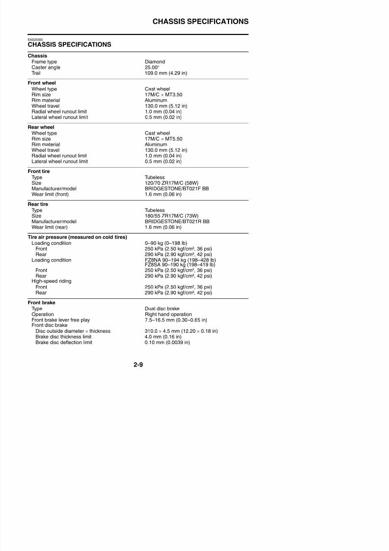
CHASSIS SPECIFICATIONS
ChassisFrame type DiamondCaster angle 25.00°Trail 109.0 mm (4.29 in)
Front wheelWheel type Cast wheelRim size 17M/C × MT3.50
Rim material AluminumWheel travel 130.0 mm (5.12 in)Radial wheel runout limit 1.0 mm (0.04 in)Lateral wheel runout limit 0.5 mm (0.02 in)
Rear wheelWheel type Cast wheelRim size 17M/C × MT5.50Rim material Aluminum
Wheel travel 130.0 mm (5.12 in)Radial wheel runout limit 1.0 mm (0.04 in)Lateral wheel runout limit 0.5 mm (0.02 in)
Front tireType TubelessSize 120/70 ZR17M/C (58W)Manufacturer/model BRIDGESTONE/BT021F BBWear limit (front) 1.6 mm (0.06 in)
Rear tireType TubelessSize 180/55 ZR17M/C (73W)Manufacturer/model BRIDGESTONE/BT021R BBWear limit (rear) 1.6 mm (0.06 in)
Tire air pressure (measured on cold tires)Loading condition 0–90 kg (0–198 lb)
Front 250 kPa (2.50 kgf/cm², 36 psi)Rear 290 kPa (2.90 kgf/cm², 42 psi)
Loading condition FZ8NA 90–194 kg (198–428 lb)FZ8SA 90–190 kg (198–419 lb)
Front 250 kPa (2.50 kgf/cm², 36 psi)
CHASSIS SPECIFICATIONS
B k d li i thi k (i ) 4 5 (0 18 i )
8/21/2019 Fz8 - Service Manual
http://slidepdf.com/reader/full/fz8-service-manual 59/609
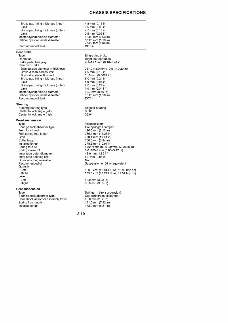
Brake pad lining thickness (inner) 4.5 mm (0.18 in)Limit 0.5 mm (0.02 in)Brake pad lining thickness (outer) 4.5 mm (0.18 in)Limit 0.5 mm (0.02 in)
Master cylinder inside diameter 16.00 mm (0.63 in)Caliper cylinder inside diameter 30.20 mm (1.19 in)
27.00 mm (1.06 in)Recommended fluid DOT 4
Rear brakeType Single disc brake
Operation Right foot operationBrake pedal free play 4.1–11.1 mm (0.16–0.44 in)Rear disc brake
Disc outside diameter × thickness 267.0 × 5.0 mm (10.51 × 0.20 in)Brake disc thickness limit 4.5 mm (0.18 in)Brake disc deflection limit 0.15 mm (0.0059 in)Brake pad lining thickness (inner) 6.0 mm (0.24 in)Limit 1.0 mm (0.04 in)Brake pad lining thickness (outer) 6.0 mm (0.24 in)
Limit 1.0 mm (0.04 in)Master cylinder inside diameter 12.7 mm (0.50 in)Caliper cylinder inside diameter 38.20 mm (1.50 in)Recommended fluid DOT 4
SteeringSteering bearing type Angular bearingCenter to lock angle (left) 33.0°Center to lock angle (right) 33.0°
Front suspensionType Telescopic forkSpring/shock absorber type Coil spring/oil damperFront fork travel 130.0 mm (5.12 in)Fork spring free length 286.1 mm (11.26 in)Limit 280.4 mm (11.04 in)Collar length 100.0 mm (3.94 in)
Installed length 278.6 mm (10.97 in)Spring rate K1 8.82 N/mm (0.90 kgf/mm, 50.36 lb/in)Spring stroke K1 0.0–130.0 mm (0.00–5.12 in)Inner tube outer diameter 43.0 mm (1.69 in)Inner tube bending limit 0.2 mm (0.01 in)Optional spring available No
CHASSIS SPECIFICATIONS
Spring rate K1 78 40 N/mm (7 99 kgf/mm 447 66 lb/in)
8/21/2019 Fz8 - Service Manual
http://slidepdf.com/reader/full/fz8-service-manual 60/609
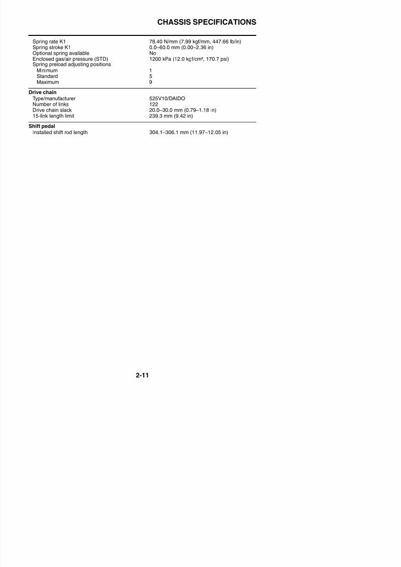
Spring rate K1 78.40 N/mm (7.99 kgf/mm, 447.66 lb/in)Spring stroke K1 0.0–60.0 mm (0.00–2.36 in)Optional spring available NoEnclosed gas/air pressure (STD) 1200 kPa (12.0 kgf/cm², 170.7 psi)Spring preload adjusting positions
Minimum 1Standard 5Maximum 9
Drive chainType/manufacturer 525V10/DAIDO
Number of links 122Drive chain slack 20.0–30.0 mm (0.79–1.18 in)15-link length limit 239.3 mm (9.42 in)
Shift pedalInstalled shift rod length 304.1–306.1 mm (11.97–12.05 in)
ELECTRICAL SPECIFICATIONS
EAS20310
8/21/2019 Fz8 - Service Manual
http://slidepdf.com/reader/full/fz8-service-manual 61/609
EAS20310
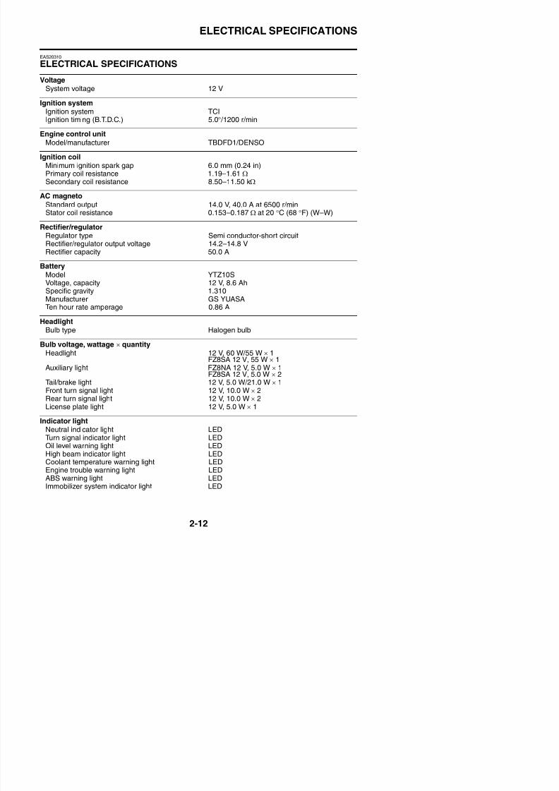
ELECTRICAL SPECIFICATIONS
VoltageSystem voltage 12 V
Ignition systemIgnition system TCIIgnition timing (B.T.D.C.) 5.0° /1200 r/min
Engine control unitModel/manufacturer TBDFD1/DENSO
Ignition coilMinimum ignition spark gap 6.0 mm (0.24 in)Primary coil resistance 1.19–1.61 ΩSecondary coil resistance 8.50–11.50 kΩ
AC magneto
Standard output 14.0 V, 40.0 A at 6500 r/minStator coil resistance 0.153–0.187 Ω at 20 °C (68 °F) (W–W)
Rectifier/regulatorRegulator type Semi conductor-short circuitRectifier/regulator output voltage 14.2–14.8 VRectifier capacity 50.0 A
BatteryModel YTZ10S
Voltage, capacity 12 V, 8.6 AhSpecific gravity 1.310Manufacturer GS YUASATen hour rate amperage 0.86 A
HeadlightBulb type Halogen bulb
Bulb voltage, wattage × quantity
Headlight 12 V, 60 W/55 W × 1FZ8SA 12 V, 55 W × 1Auxiliary light FZ8NA 12 V, 5.0 W × 1
FZ8SA 12 V, 5.0 W × 2Tail/brake light 12 V, 5.0 W/21.0 W × 1Front turn signal light 12 V 10 0 W × 2
ELECTRICAL SPECIFICATIONS
8/21/2019 Fz8 - Service Manual
http://slidepdf.com/reader/full/fz8-service-manual 62/609
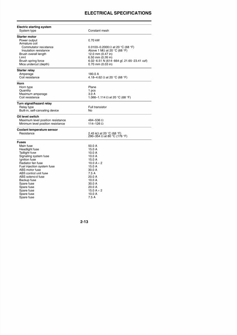
Electric starting systemSystem type Constant mesh
Starter motorPower output 0.70 kWArmature coil
Commutator resistance 0.0100–0.2000 Ω at 20 °C (68 °F)Insulation resistance Above 1 MΩ at 20 °C (68 °F)
Brush overall length 12.0 mm (0.47 in)Limit 6.50 mm (0.26 in)Brush spring force 6.02–6.51 N (614–664 gf, 21.65–23.41 ozf)Mica undercut (depth) 0.70 mm (0.03 in)
Starter relayAmperage 180.0 ACoil resistance 4.18–4.62 Ω at 20 °C (68 °F)
HornHorn type Plane
Quantity 1 pcsMaximum amperage 3.0 ACoil resistance 1.066–1.114 Ω at 20 °C (68 °F)
Turn signal/hazard relayRelay type Full transistorBuilt-in, self-canceling device No
Oil level switch
Maximum level position resistance 484–536 ΩMinimum level position resistance 114–126 Ω
Coolant temperature sensor
Resistance 2.45 kΩ at 20 °C (68 °F)290–354 Ω at 80 °C (176 °F)
FusesMain fuse 50.0 A
Headlight fuse 15.0 ATaillight fuse 10.0 ASignaling system fuse 10.0 AIgnition fuse 15.0 ARadiator fan fuse 10.0 A × 2Fuel injection system fuse 15 0 A
TIGHTENING TORQUES
EAS20320
TIGHTENING TORQUES
8/21/2019 Fz8 - Service Manual
http://slidepdf.com/reader/full/fz8-service-manual 63/609
TIGHTENING TORQUES
EAS20331
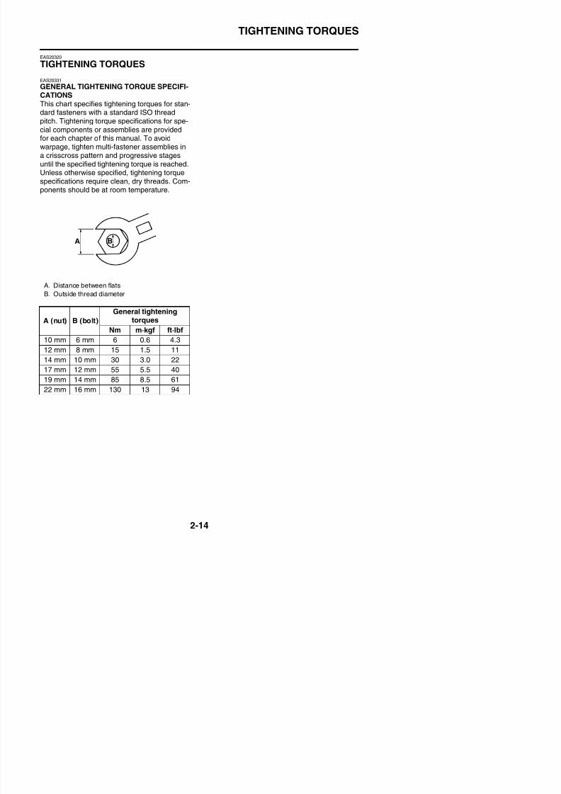
GENERAL TIGHTENING TORQUE SPECIFI-CATIONSThis chart specifies tightening torques for stan-dard fasteners with a standard ISO threadpitch. Tightening torque specifications for spe-cial components or assemblies are providedfor each chapter of this manual. To avoid
warpage, tighten multi-fastener assemblies ina crisscross pattern and progressive stagesuntil the specified tightening torque is reached.Unless otherwise specified, tightening torquespecifications require clean, dry threads. Com-ponents should be at room temperature.
A. Distance between flatsB. Outside thread diameter
A (nut) B (bolt)
General tighteningtorques
Nm m·kgf ft·lbf
10 mm 6 mm 6 0.6 4.3
12 mm 8 mm 15 1.5 11
14 mm 10 mm 30 3.0 22
17 mm 12 mm 55 5.5 40
19 mm 14 mm 85 8.5 61
22 mm 16 mm 130 13 94
TIGHTENING TORQUES
EAS20340
ENGINE TIGHTENING TORQUES
8/21/2019 Fz8 - Service Manual
http://slidepdf.com/reader/full/fz8-service-manual 64/609
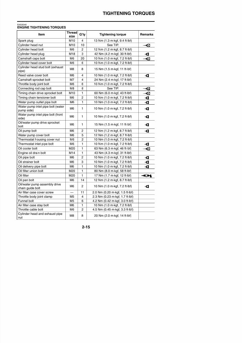
ENGINE TIGHTENING TORQUES
ItemThread
size Q’ty Tightening torque Remarks
Spark plug M10 4 13 Nm (1.3 m·kgf, 9.4 ft·lbf)
Cylinder head nut M10 10 See TIP.
Cylinder head bolt M6 2 12 Nm (1.2 m·kgf, 8.7 ft·lbf)
Cylinder head plug M18 3 42 Nm (4.2 m·kgf, 30 ft·lbf)
Camshaft caps bolt M6 20 10 Nm (1.0 m·kgf, 7.2 ft·lbf)
Cylinder head cover bolt M6 6 10 Nm (1.0 m·kgf, 7.2 ft·lbf)Cylinder head stud bolt (exhaustpipe)
M8 8 15 Nm (1.5 m·kgf, 11 ft·lbf)
Reed valve cover bolt M6 4 10 Nm (1.0 m·kgf, 7.2 ft·lbf)
Camshaft sprocket bolt M7 4 24 Nm (2.4 m·kgf, 17 ft·lbf)
Throttle body joint bolt M6 6 10 Nm (1.0 m·kgf, 7.2 ft·lbf)
Connecting rod cap bolt M8 8 See TIP.
Timing chain drive sprocket bolt M10 1 60 Nm (6.0 m·kgf, 43 ft·lbf)Timing chain tensioner bolt M6 2 10 Nm (1.0 m·kgf, 7.2 ft·lbf)
Water pump outlet pipe bolt M6 1 10 Nm (1.0 m·kgf, 7.2 ft·lbf)
Water pump inlet pipe bolt (waterpump side)
M6 1 10 Nm (1.0 m·kgf, 7.2 ft·lbf)
Water pump inlet pipe bolt (frontside)
M6 1 10 Nm (1.0 m·kgf, 7.2 ft·lbf)
Oil/water pump drive sprocketbolt M6 1 15 Nm (1.5 m·kgf, 11 ft·lbf)
Oil pump bolt M6 2 12 Nm (1.2 m·kgf, 8.7 ft·lbf)
Water pump cover bolt M6 5 12 Nm (1.2 m·kgf, 8.7 ft·lbf)
Thermostat housing cover nut M6 2 10 Nm (1.0 m·kgf, 7.2 ft·lbf)
Thermostat inlet pipe bolt M6 1 10 Nm (1.0 m·kgf, 7.2 ft·lbf)
Oil cooler bolt M20 1 63 Nm (6.3 m·kgf, 46 ft·lbf)
Engine oil drain bolt M14 1 43 Nm (4.3 m·kgf, 31 ft·lbf)Oil pipe bolt M6 2 10 Nm (1.0 m·kgf, 7.2 ft·lbf)
Oil strainer bolt M6 3 10 Nm (1.0 m·kgf, 7.2 ft·lbf)
Oil delivery pipe bolt M6 1 10 Nm (1.0 m·kgf, 7.2 ft·lbf)
Oil filt i b lt M20 1 80 N (8 0 k f 58 ft lbf)
E
LT
E
LT
M
E
LT
LT
LT
LT
LT
LT
LT
E
LT
LT
LT
TIGHTENING TORQUES
ItThread
Q’t Ti ht i t R k
8/21/2019 Fz8 - Service Manual
http://slidepdf.com/reader/full/fz8-service-manual 65/609
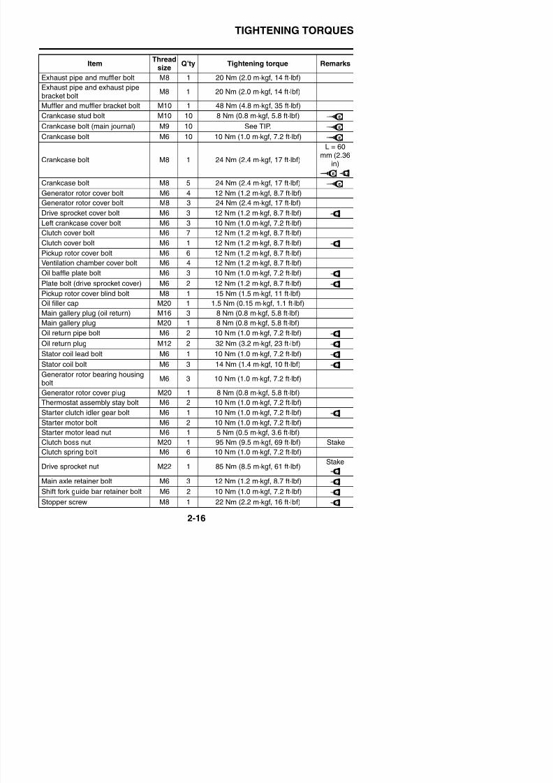
Exhaust pipe and muffler bolt M8 1 20 Nm (2.0 m·kgf, 14 ft·lbf)Exhaust pipe and exhaust pipebracket bolt
M8 1 20 Nm (2.0 m·kgf, 14 ft·lbf)
Muffler and muffler bracket bolt M10 1 48 Nm (4.8 m·kgf, 35 ft·lbf)
Crankcase stud bolt M10 10 8 Nm (0.8 m·kgf, 5.8 ft·lbf)
Crankcase bolt (main journal) M9 10 See TIP.
Crankcase bolt M6 10 10 Nm (1.0 m·kgf, 7.2 ft·lbf)
Crankcase bolt M8 1 24 Nm (2.4 m·kgf, 17 ft·lbf)
L = 60mm (2.36
in)
Crankcase bolt M8 5 24 Nm (2.4 m·kgf, 17 ft·lbf)
Generator rotor cover bolt M6 4 12 Nm (1.2 m·kgf, 8.7 ft·lbf)
Generator rotor cover bolt M8 3 24 Nm (2.4 m·kgf, 17 ft·lbf)
Drive sprocket cover bolt M6 3 12 Nm (1.2 m·kgf, 8.7 ft·lbf)Left crankcase cover bolt M6 3 10 Nm (1.0 m·kgf, 7.2 ft·lbf)
Clutch cover bolt M6 7 12 Nm (1.2 m·kgf, 8.7 ft·lbf)
Clutch cover bolt M6 1 12 Nm (1.2 m·kgf, 8.7 ft·lbf)
Pickup rotor cover bolt M6 6 12 Nm (1.2 m·kgf, 8.7 ft·lbf)
Ventilation chamber cover bolt M6 4 12 Nm (1.2 m·kgf, 8.7 ft·lbf)
Oil baffle plate bolt M6 3 10 Nm (1.0 m·kgf, 7.2 ft·lbf)
Plate bolt (drive sprocket cover) M6 2 12 Nm (1.2 m·kgf, 8.7 ft·lbf)Pickup rotor cover blind bolt M8 1 15 Nm (1.5 m·kgf, 11 ft·lbf)
Oil filler cap M20 1 1.5 Nm (0.15 m·kgf, 1.1 ft·lbf)
Main gallery plug (oil return) M16 3 8 Nm (0.8 m·kgf, 5.8 ft·lbf)
Main gallery plug M20 1 8 Nm (0.8 m·kgf, 5.8 ft·lbf)
Oil return pipe bolt M6 2 10 Nm (1.0 m·kgf, 7.2 ft·lbf)
Oil return plug M12 2 32 Nm (3.2 m·kgf, 23 ft·lbf)
Stator coil lead bolt M6 1 10 Nm (1.0 m·kgf, 7.2 ft·lbf)
Stator coil bolt M6 3 14 Nm (1.4 m·kgf, 10 ft·lbf)
Generator rotor bearing housingbolt
M6 3 10 Nm (1.0 m·kgf, 7.2 ft·lbf)
ItemThread
sizeQ’ty Tightening torque Remarks
E
E
E
E LT
E
LT
LT
LT
LT
LT
LT
LT
LT
TIGHTENING TORQUES
ItemThread
Q’ty Tightening torque Remarks
8/21/2019 Fz8 - Service Manual
http://slidepdf.com/reader/full/fz8-service-manual 66/609
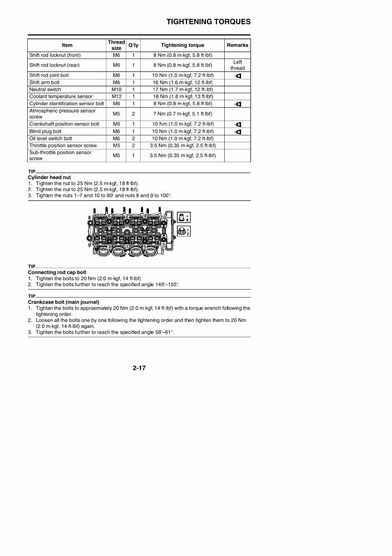
TIP
Cylinder head nut1. Tighten the nut to 25 Nm (2.5 m·kgf, 18 ft·lbf).2. Tighten the nut to 25 Nm (2.5 m·kgf, 18 ft·lbf).3. Tighten the nuts 1–7 and 10 to 80° and nuts 8 and 9 to 100°.
TIP
Connecting rod cap bolt
Shift rod locknut (front) M6 1 8 Nm (0.8 m·kgf, 5.8 ft·lbf)
Shift rod locknut (rear) M6 1 8 Nm (0.8 m·kgf, 5.8 ft·lbf)Left
thread
Shift rod joint bolt M6 1 10 Nm (1.0 m·kgf, 7.2 ft·lbf)
Shift arm bolt M6 1 16 Nm (1.6 m·kgf, 12 ft·lbf)
Neutral switch M10 1 17 Nm (1.7 m·kgf, 12 ft·lbf)
Coolant temperature sensor M12 1 18 Nm (1.8 m·kgf, 13 ft·lbf)
Cylinder identification sensor bolt M6 1 8 Nm (0.8 m·kgf, 5.8 ft·lbf)Atmospheric pressure sensorscrew
M5 2 7 Nm (0.7 m·kgf, 5.1 ft·lbf)
Crankshaft position sensor bolt M6 1 10 Nm (1.0 m·kgf, 7.2 ft·lbf)
Blind plug bolt M6 1 10 Nm (1.0 m·kgf, 7.2 ft·lbf)
Oil level switch bolt M6 2 10 Nm (1.0 m·kgf, 7.2 ft·lbf)
Throttle position sensor screw M5 2 3.5 Nm (0.35 m·kgf, 2.5 ft·lbf)
Sub-throttle position sensorscrew
M5 1 3.5 Nm (0.35 m·kgf, 2.5 ft·lbf)
Itemsize
Q’ty Tightening torque Remarks
LT
LT
LT
LT
TIGHTENING TORQUES
8/21/2019 Fz8 - Service Manual
http://slidepdf.com/reader/full/fz8-service-manual 67/609
TIGHTENING TORQUES
EAS20350
CHASSIS TIGHTENING TORQUES
8/21/2019 Fz8 - Service Manual
http://slidepdf.com/reader/full/fz8-service-manual 68/609
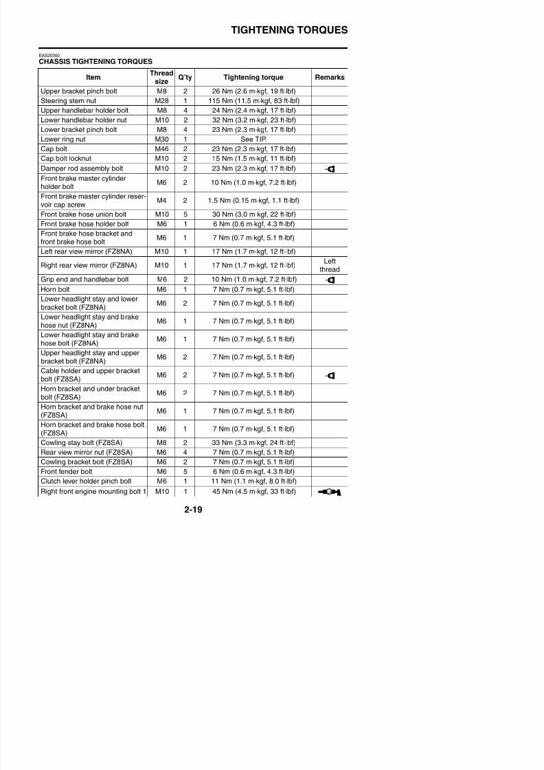
CHASSIS TIGHTENING TORQUES
ItemThread
size Q’ty Tightening torque Remarks
Upper bracket pinch bolt M8 2 26 Nm (2.6 m·kgf, 19 ft·lbf)
Steering stem nut M28 1 115 Nm (11.5 m·kgf, 83 ft·lbf)
Upper handlebar holder bolt M8 4 24 Nm (2.4 m·kgf, 17 ft·lbf)
Lower handlebar holder nut M10 2 32 Nm (3.2 m·kgf, 23 ft·lbf)
Lower bracket pinch bolt M8 4 23 Nm (2.3 m·kgf, 17 ft·lbf)
Lower ring nut M30 1 See TIP.
Cap bolt M46 2 23 Nm (2.3 m·kgf, 17 ft·lbf)
Cap bolt locknut M10 2 15 Nm (1.5 m·kgf, 11 ft·lbf)
Damper rod assembly bolt M10 2 23 Nm (2.3 m·kgf, 17 ft·lbf)
Front brake master cylinderholder bolt
M6 2 10 Nm (1.0 m·kgf, 7.2 ft·lbf)
Front brake master cylinder reser-voir cap screw
M4 2 1.5 Nm (0.15 m·kgf, 1.1 ft·lbf)
Front brake hose union bolt M10 5 30 Nm (3.0 m·kgf, 22 ft·lbf)
Front brake hose holder bolt M6 1 6 Nm (0.6 m·kgf, 4.3 ft·lbf)
Front brake hose bracket andfront brake hose bolt
M6 1 7 Nm (0.7 m·kgf, 5.1 ft·lbf)
Left rear view mirror (FZ8NA) M10 1 17 Nm (1.7 m·kgf, 12 ft·lbf)
Right rear view mirror (FZ8NA) M10 1 17 Nm (1.7 m·kgf, 12 ft·lbf)Left
thread
Grip end and handlebar bolt M6 2 10 Nm (1.0 m·kgf, 7.2 ft·lbf)Horn bolt M6 1 7 Nm (0.7 m·kgf, 5.1 ft·lbf)
Lower headlight stay and lowerbracket bolt (FZ8NA)
M6 2 7 Nm (0.7 m·kgf, 5.1 ft·lbf)
Lower headlight stay and brakehose nut (FZ8NA)
M6 1 7 Nm (0.7 m·kgf, 5.1 ft·lbf)
Lower headlight stay and brake
hose bolt (FZ8NA)
M6 1 7 Nm (0.7 m·kgf, 5.1 ft·lbf)
Upper headlight stay and upperbracket bolt (FZ8NA)
M6 2 7 Nm (0.7 m·kgf, 5.1 ft·lbf)
Cable holder and upper bracketbolt (FZ8SA)
M6 2 7 Nm (0.7 m·kgf, 5.1 ft·lbf)
LT
LT
LT
TIGHTENING TORQUES
ItemThread
iQ’ty Tightening torque Remarks
8/21/2019 Fz8 - Service Manual
http://slidepdf.com/reader/full/fz8-service-manual 69/609
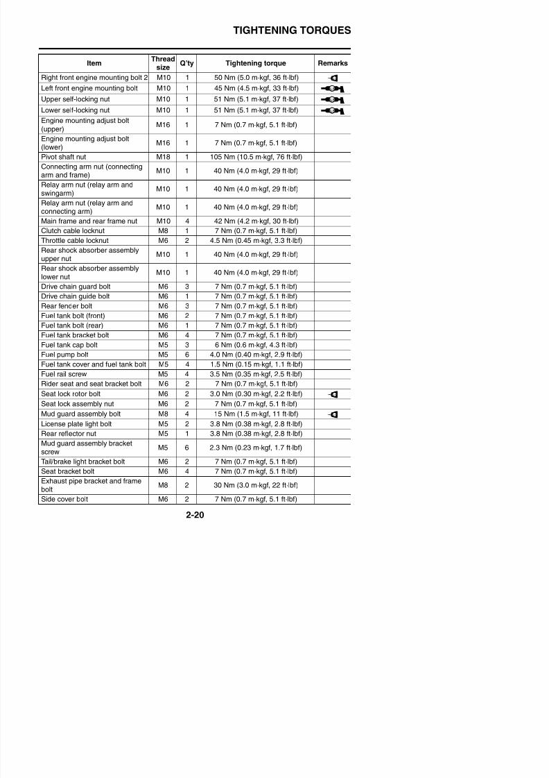
Right front engine mounting bolt 2 M10 1 50 Nm (5.0 m·kgf, 36 ft·lbf)Left front engine mounting bolt M10 1 45 Nm (4.5 m·kgf, 33 ft·lbf)
Upper self-locking nut M10 1 51 Nm (5.1 m·kgf, 37 ft·lbf)
Lower self-locking nut M10 1 51 Nm (5.1 m·kgf, 37 ft·lbf)
Engine mounting adjust bolt
(upper)M16 1 7 Nm (0.7 m·kgf, 5.1 ft·lbf)
Engine mounting adjust bolt
(lower) M16 1 7 Nm (0.7 m·kgf, 5.1 ft·lbf)Pivot shaft nut M18 1 105 Nm (10.5 m·kgf, 76 ft·lbf)
Connecting arm nut (connectingarm and frame)
M10 1 40 Nm (4.0 m·kgf, 29 ft·lbf)
Relay arm nut (relay arm andswingarm)
M10 1 40 Nm (4.0 m·kgf, 29 ft·lbf)
Relay arm nut (relay arm and
connecting arm)
M10 1 40 Nm (4.0 m·kgf, 29 ft·lbf)
Main frame and rear frame nut M10 4 42 Nm (4.2 m·kgf, 30 ft·lbf)
Clutch cable locknut M8 1 7 Nm (0.7 m·kgf, 5.1 ft·lbf)
Throttle cable locknut M6 2 4.5 Nm (0.45 m·kgf, 3.3 ft·lbf)
Rear shock absorber assemblyupper nut
M10 1 40 Nm (4.0 m·kgf, 29 ft·lbf)
Rear shock absorber assemblylower nut
M10 1 40 Nm (4.0 m·kgf, 29 ft·lbf)
Drive chain guard bolt M6 3 7 Nm (0.7 m·kgf, 5.1 ft·lbf)
Drive chain guide bolt M6 1 7 Nm (0.7 m·kgf, 5.1 ft·lbf)
Rear fender bolt M6 3 7 Nm (0.7 m·kgf, 5.1 ft·lbf)
Fuel tank bolt (front) M6 2 7 Nm (0.7 m·kgf, 5.1 ft·lbf)
Fuel tank bolt (rear) M6 1 7 Nm (0.7 m·kgf, 5.1 ft·lbf)
Fuel tank bracket bolt M6 4 7 Nm (0.7 m·kgf, 5.1 ft·lbf)
Fuel tank cap bolt M5 3 6 Nm (0.6 m·kgf, 4.3 ft·lbf)
Fuel pump bolt M5 6 4.0 Nm (0.40 m·kgf, 2.9 ft·lbf)
Fuel tank cover and fuel tank bolt M5 4 1.5 Nm (0.15 m·kgf, 1.1 ft·lbf)
Fuel rail screw M5 4 3.5 Nm (0.35 m·kgf, 2.5 ft·lbf)
Rider seat and seat bracket bolt M6 2 7 Nm (0.7 m·kgf, 5.1 ft·lbf)
Itemsize
Q ty Tightening torque Remarks
LT
LS
LS
LS
TIGHTENING TORQUES
ItemThread
sizeQ’ty Tightening torque Remarks
8/21/2019 Fz8 - Service Manual
http://slidepdf.com/reader/full/fz8-service-manual 70/609
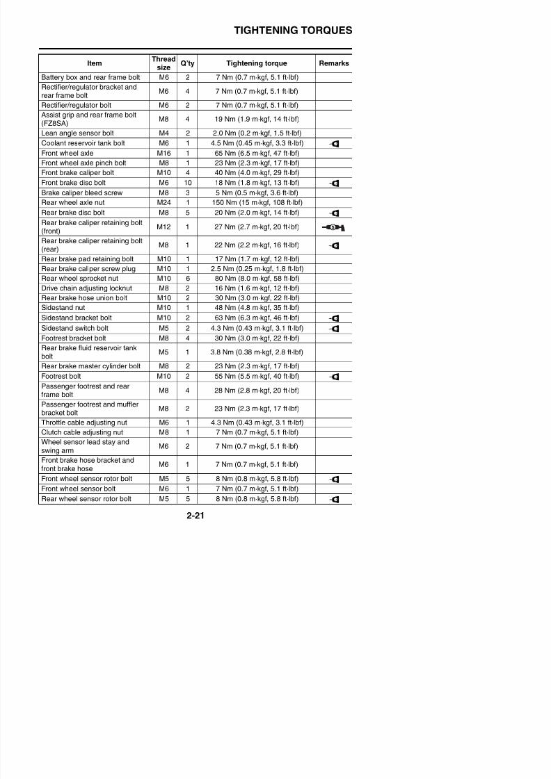
Battery box and rear frame bolt M6 2 7 Nm (0.7 m·kgf, 5.1 ft·lbf)Rectifier/regulator bracket andrear frame bolt
M6 4 7 Nm (0.7 m·kgf, 5.1 ft·lbf)
Rectifier/regulator bolt M6 2 7 Nm (0.7 m·kgf, 5.1 ft·lbf)
Assist grip and rear frame bolt(FZ8SA)
M8 4 19 Nm (1.9 m·kgf, 14 ft·lbf)
Lean angle sensor bolt M4 2 2.0 Nm (0.2 m·kgf, 1.5 ft·lbf)
Coolant reservoir tank bolt M6 1 4.5 Nm (0.45 m·kgf, 3.3 ft·lbf)
Front wheel axle M16 1 65 Nm (6.5 m·kgf, 47 ft·lbf)
Front wheel axle pinch bolt M8 1 23 Nm (2.3 m·kgf, 17 ft·lbf)
Front brake caliper bolt M10 4 40 Nm (4.0 m·kgf, 29 ft·lbf)
Front brake disc bolt M6 10 18 Nm (1.8 m·kgf, 13 ft·lbf)
Brake caliper bleed screw M8 3 5 Nm (0.5 m·kgf, 3.6 ft·lbf)
Rear wheel axle nut M24 1 150 Nm (15 m·kgf, 108 ft·lbf)
Rear brake disc bolt M8 5 20 Nm (2.0 m·kgf, 14 ft·lbf)Rear brake caliper retaining bolt(front)
M12 1 27 Nm (2.7 m·kgf, 20 ft·lbf)
Rear brake caliper retaining bolt(rear)
M8 1 22 Nm (2.2 m·kgf, 16 ft·lbf)
Rear brake pad retaining bolt M10 1 17 Nm (1.7 m·kgf, 12 ft·lbf)
Rear brake caliper screw plug M10 1 2.5 Nm (0.25 m·kgf, 1.8 ft·lbf)
Rear wheel sprocket nut M10 6 80 Nm (8.0 m·kgf, 58 ft·lbf)
Drive chain adjusting locknut M8 2 16 Nm (1.6 m·kgf, 12 ft·lbf)
Rear brake hose union bolt M10 2 30 Nm (3.0 m·kgf, 22 ft·lbf)
Sidestand nut M10 1 48 Nm (4.8 m·kgf, 35 ft·lbf)
Sidestand bracket bolt M10 2 63 Nm (6.3 m·kgf, 46 ft·lbf)
Sidestand switch bolt M5 2 4.3 Nm (0.43 m·kgf, 3.1 ft·lbf)
Footrest bracket bolt M8 4 30 Nm (3.0 m·kgf, 22 ft·lbf)
Rear brake fluid reservoir tankbolt M5 1 3.8 Nm (0.38 m·kgf, 2.8 ft·lbf)
Rear brake master cylinder bolt M8 2 23 Nm (2.3 m·kgf, 17 ft·lbf)
Footrest bolt M10 2 55 Nm (5.5 m·kgf, 40 ft·lbf)
Passenger footrest and rear
sizey g g q
LT
LT
LT
LT
LT
LT
LT
TIGHTENING TORQUES
ItemThread
sizeQ’ty Tightening torque Remarks
8/21/2019 Fz8 - Service Manual
http://slidepdf.com/reader/full/fz8-service-manual 71/609
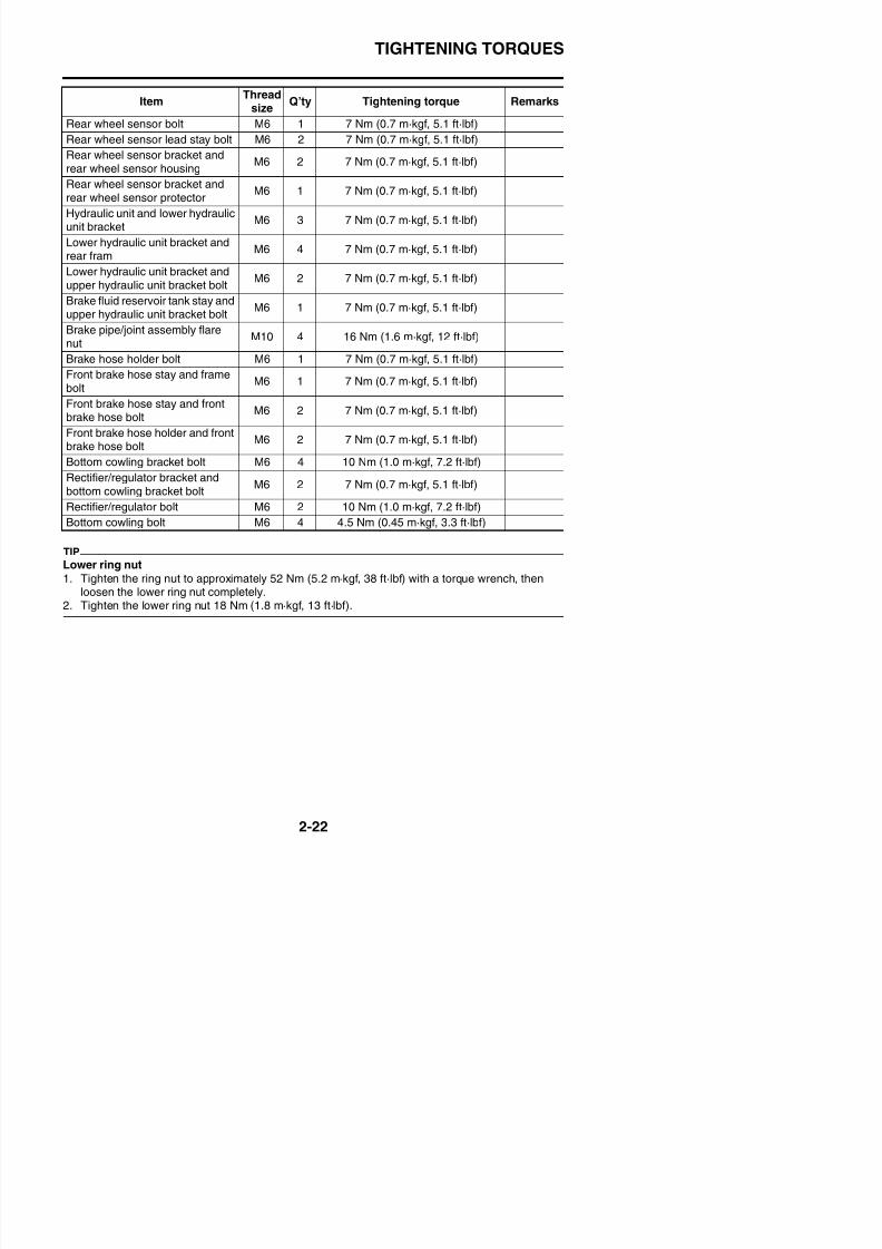
TIP
Lower ring nut1. Tighten the ring nut to approximately 52 Nm (5.2 m·kgf, 38 ft·lbf) with a torque wrench, then
loosen the lower ring nut completely.2. Tighten the lower ring nut 18 Nm (1.8 m·kgf, 13 ft·lbf).
Rear wheel sensor bolt M6 1 7 Nm (0.7 m·kgf, 5.1 ft·lbf)Rear wheel sensor lead stay bolt M6 2 7 Nm (0.7 m·kgf, 5.1 ft·lbf)
Rear wheel sensor bracket andrear wheel sensor housing
M6 2 7 Nm (0.7 m·kgf, 5.1 ft·lbf)
Rear wheel sensor bracket andrear wheel sensor protector
M6 1 7 Nm (0.7 m·kgf, 5.1 ft·lbf)
Hydraulic unit and lower hydraulicunit bracket
M6 3 7 Nm (0.7 m·kgf, 5.1 ft·lbf)
Lower hydraulic unit bracket andrear fram
M6 4 7 Nm (0.7 m·kgf, 5.1 ft·lbf)
Lower hydraulic unit bracket andupper hydraulic unit bracket bolt
M6 2 7 Nm (0.7 m·kgf, 5.1 ft·lbf)
Brake fluid reservoir tank stay andupper hydraulic unit bracket bolt
M6 1 7 Nm (0.7 m·kgf, 5.1 ft·lbf)
Brake pipe/joint assembly flare
nutM10 4 16 Nm (1.6 m·kgf, 12 ft·lbf)
Brake hose holder bolt M6 1 7 Nm (0.7 m·kgf, 5.1 ft·lbf)
Front brake hose stay and framebolt
M6 1 7 Nm (0.7 m·kgf, 5.1 ft·lbf)
Front brake hose stay and frontbrake hose bolt
M6 2 7 Nm (0.7 m·kgf, 5.1 ft·lbf)
Front brake hose holder and frontbrake hose bolt
M6 2 7 Nm (0.7 m·kgf, 5.1 ft·lbf)
Bottom cowling bracket bolt M6 4 10 Nm (1.0 m·kgf, 7.2 ft·lbf)
Rectifier/regulator bracket andbottom cowling bracket bolt
M6 2 7 Nm (0.7 m·kgf, 5.1 ft·lbf)
Rectifier/regulator bolt M6 2 10 Nm (1.0 m·kgf, 7.2 ft·lbf)
Bottom cowling bolt M6 4 4.5 Nm (0.45 m·kgf, 3.3 ft·lbf)
size
LUBRICATION POINTS AND LUBRICANT TYPES
EAS20360
LUBRICATION POINTS AND LUBRICANT TYPES
8/21/2019 Fz8 - Service Manual
http://slidepdf.com/reader/full/fz8-service-manual 72/609
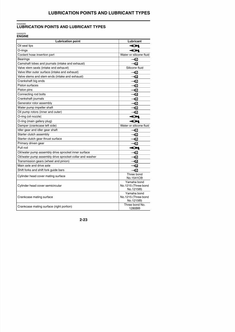
EAS20370ENGINE
Lubrication point Lubricant
Oil seal lips
O-rings
Coolant hose insertion part Water or silicone fluid
Bearings
Camshaft lobes and journals (intake and exhaust)
Valve stem seals (intake and exhaust) Silicone fluid
Valve lifter outer surface (intake and exhaust)
Valve stems and stem ends (intake and exhaust)
Crankshaft big ends
Piston surfaces
Piston pins
Connecting rod bolts
Crankshaft journals
Generator rotor assembly
Water pump impeller shaft
Oil pump rotors (inner and outer)
O-ring (oil nozzle)
O-ring (main gallery plug)
Damper (crankcase left side) Water or silicone fluid
Idler gear and idler gear shaft
Starter clutch assembly
Starter clutch gear thrust surface
Primary driven gear
Pull rod
Oil/water pump assembly drive sprocket inner surface
Oil/water pump assembly drive sprocket collar and washer
Transmission gears (wheel and pinion)
M i l d d i l
LS
LS
E
M
E
M
E
E
E
M
E
E
E
E
LS
LS
E
E
E
E
LS
E
E
M
LUBRICATION POINTS AND LUBRICANT TYPES
Yamaha bond
Lubrication point Lubricant
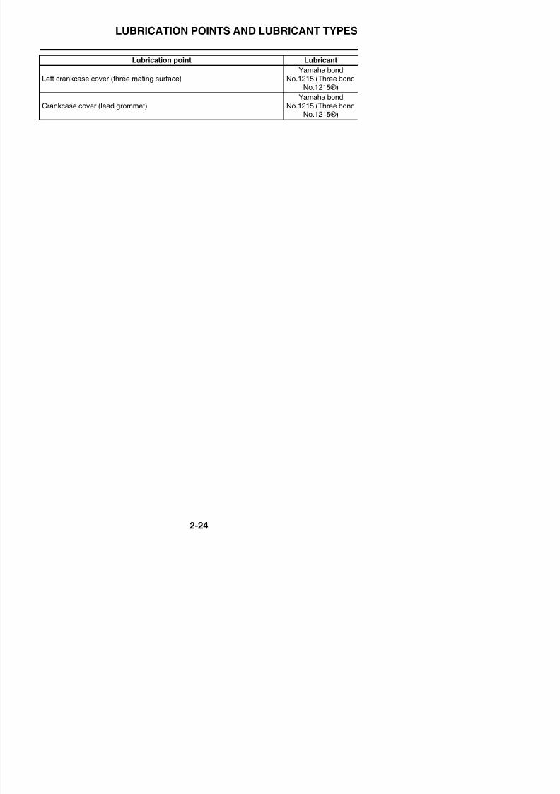
8/21/2019 Fz8 - Service Manual
http://slidepdf.com/reader/full/fz8-service-manual 73/609
Left crankcase cover (three mating surface)
Yamaha bond
No.1215 (Three bondNo.1215®)
Crankcase cover (lead grommet)Yamaha bond
No.1215 (Three bondNo.1215®)
LUBRICATION POINTS AND LUBRICANT TYPES
EAS20380
CHASSIS
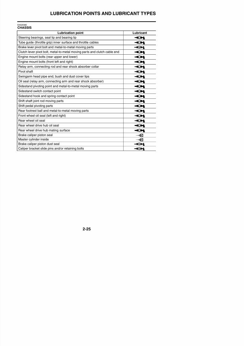
8/21/2019 Fz8 - Service Manual
http://slidepdf.com/reader/full/fz8-service-manual 74/609
Lubrication point Lubricant
Steering bearings, seal lip and bearing lip
Tube guide (throttle grip) inner surface and throttle cables
Brake lever pivot bolt and metal-to-metal moving parts
Clutch lever pivot bolt, metal-to-metal moving parts and clutch cable end
Engine mount bolts (rear upper and lower)
Engine mount bolts (front left and right)
Relay arm, connecting rod and rear shock absorber collar
Pivot shaft
Swingarm head pipe end, bush and dust cover lips
Oil seal (relay arm, connecting arm and rear shock absorber)
Sidestand pivoting point and metal-to-metal moving parts
Sidestand switch contact point
Sidestand hook and spring contact point
Shift shaft joint rod moving parts
Shift pedal pivoting parts
Rear footrest ball and metal-to-metal moving parts
Front wheel oil seal (left and right)
Rear wheel oil seal
Rear wheel drive hub oil sealRear wheel drive hub mating surface
Brake caliper piston seal
Master cylinder inside
Brake caliper piston dust seal
Caliper bracket slide pins and/or retaining bolts
LS
LS
LS
LS
LS
LS
LS
LS
LS
LS
LS
LS
LS
LS
LS
LS
LS
LS
LS
LUBRICATION POINTS AND LUBRICANT TYPES

8/21/2019 Fz8 - Service Manual
http://slidepdf.com/reader/full/fz8-service-manual 75/609
LUBRICATION SYSTEM CHART AND DIAGRAMS
EAS20390
LUBRICATION SYSTEM CHART AND DIAGRAMS
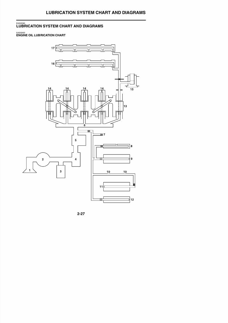
8/21/2019 Fz8 - Service Manual
http://slidepdf.com/reader/full/fz8-service-manual 76/609
EAS20400ENGINE OIL LUBRICATION CHART
LUBRICATION SYSTEM CHART AND DIAGRAMS
1. Oil strainer
2. Oil pump
R li f l
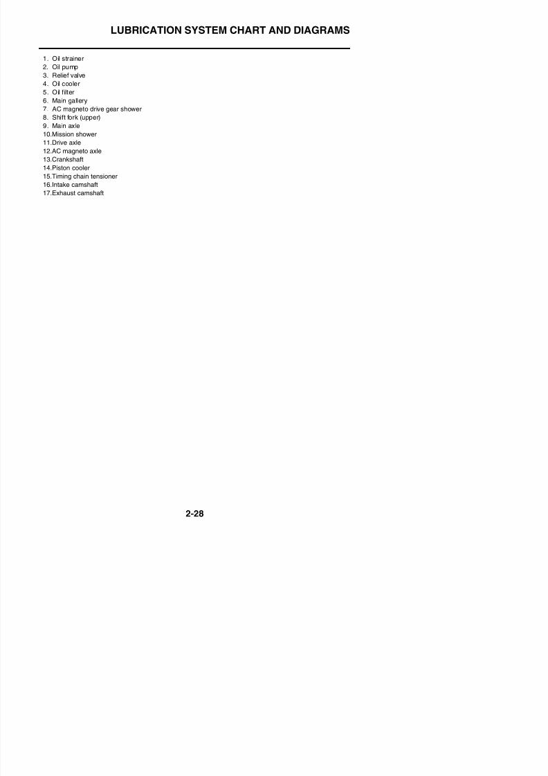
8/21/2019 Fz8 - Service Manual
http://slidepdf.com/reader/full/fz8-service-manual 77/609
3. Relief valve
4. Oil cooler
5. Oil filter
6. Main gallery
7. AC magneto drive gear shower
8. Shift fork (upper)
9. Main axle
10.Mission shower
11.Drive axle
12.AC magneto axle
13.Crankshaft
14.Piston cooler
15.Timing chain tensioner
16.Intake camshaft
17.Exhaust camshaft
LUBRICATION SYSTEM CHART AND DIAGRAMS
EAS20410
LUBRICATION DIAGRAMS
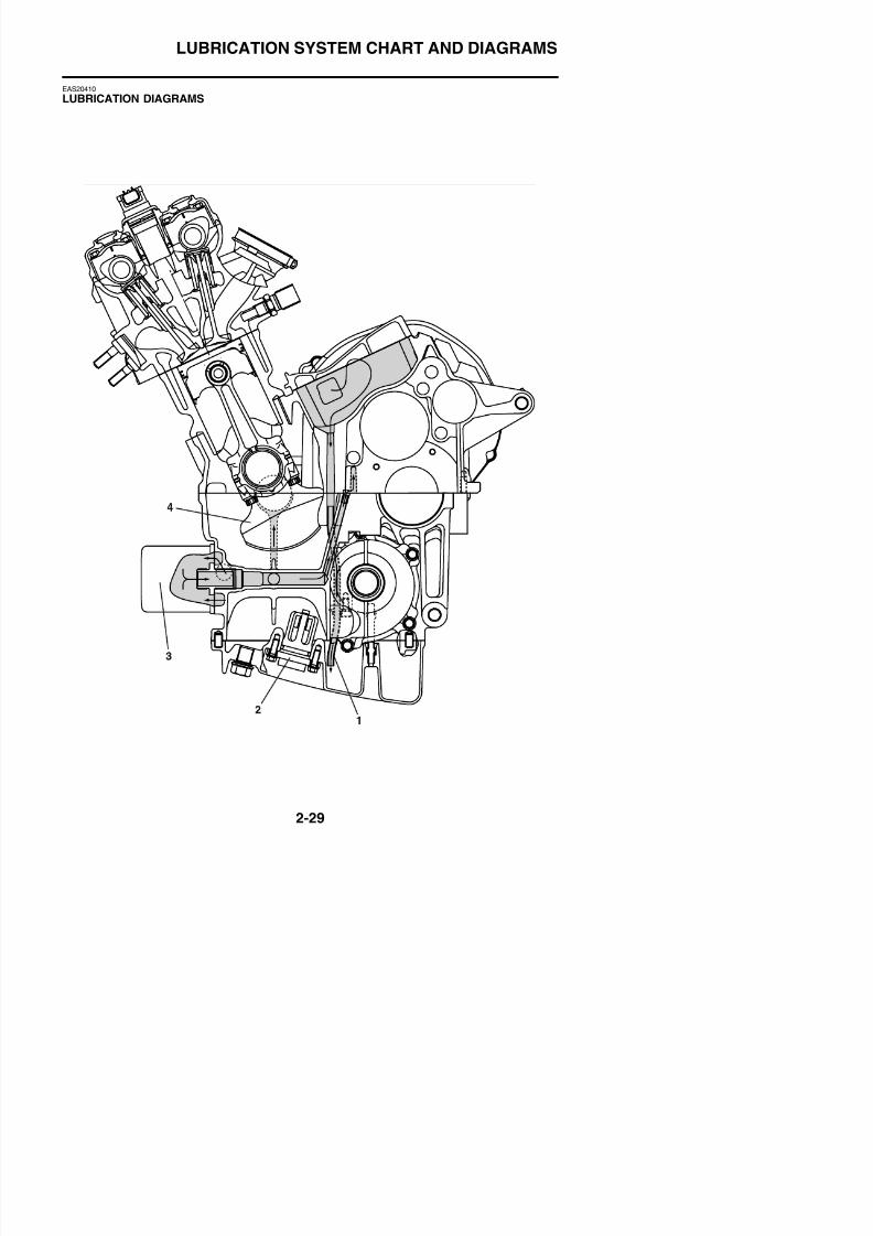
8/21/2019 Fz8 - Service Manual
http://slidepdf.com/reader/full/fz8-service-manual 78/609
LUBRICATION SYSTEM CHART AND DIAGRAMS
1. Oil delivery pipe
2. Oil level switch
3 Oil filter cartridge
8/21/2019 Fz8 - Service Manual
http://slidepdf.com/reader/full/fz8-service-manual 79/609
3. Oil filter cartridge
4. Crankshaft
LUBRICATION SYSTEM CHART AND DIAGRAMS
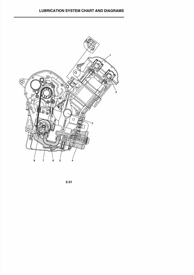
8/21/2019 Fz8 - Service Manual
http://slidepdf.com/reader/full/fz8-service-manual 80/609
2
3
1
LUBRICATION SYSTEM CHART AND DIAGRAMS
1. Intake camshaft
2. Exhaust camshaft
3 Crankshaft
8/21/2019 Fz8 - Service Manual
http://slidepdf.com/reader/full/fz8-service-manual 81/609
3. Crankshaft
4. Oil cooler
5. Relief valve
6. Oil pipe
7. Oil strainer
8. Oil pump
LUBRICATION SYSTEM CHART AND DIAGRAMS
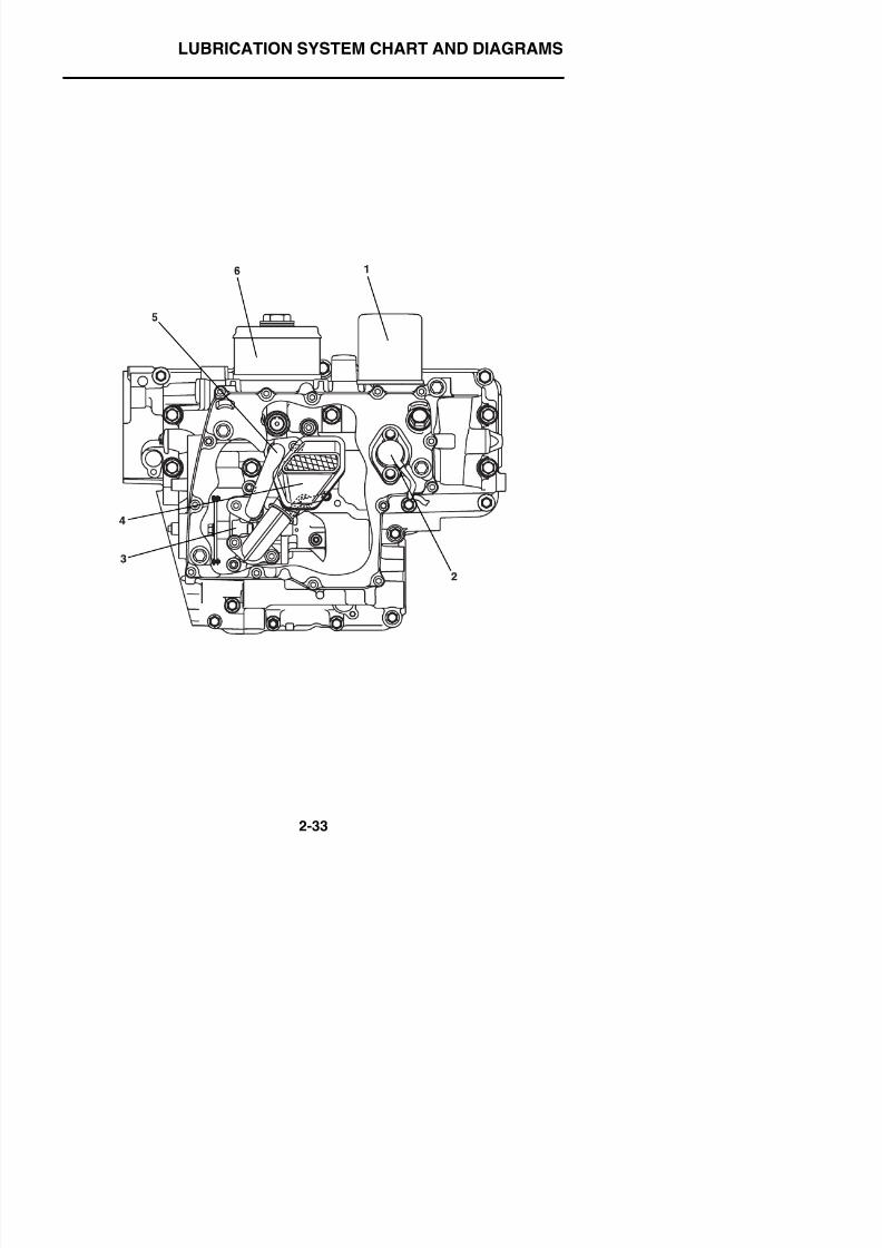
8/21/2019 Fz8 - Service Manual
http://slidepdf.com/reader/full/fz8-service-manual 82/609
LUBRICATION SYSTEM CHART AND DIAGRAMS
1. Oil filter cartridge
2. Oil level switch
3. Oil pump
8/21/2019 Fz8 - Service Manual
http://slidepdf.com/reader/full/fz8-service-manual 83/609
p p
4. Oil strainer
5. Oil pipe
6. Oil cooler
LUBRICATION SYSTEM CHART AND DIAGRAMS
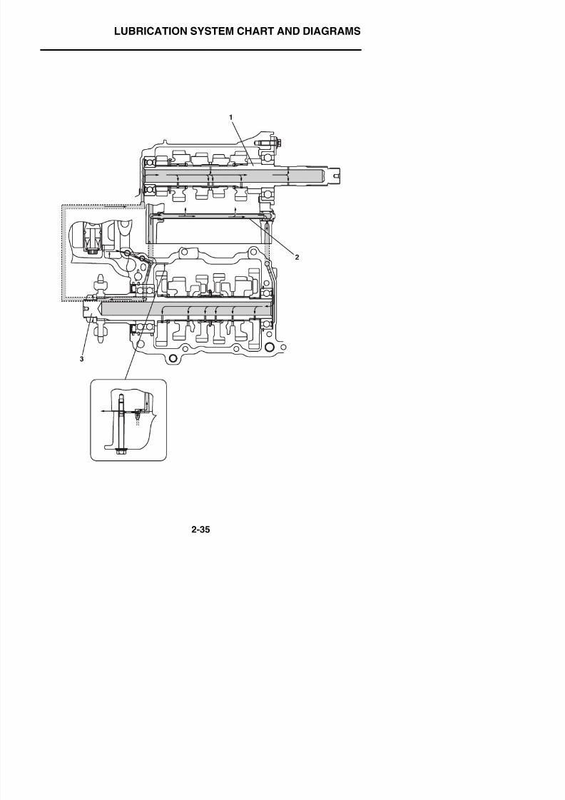
8/21/2019 Fz8 - Service Manual
http://slidepdf.com/reader/full/fz8-service-manual 84/609
LUBRICATION SYSTEM CHART AND DIAGRAMS
1. Main axle
2. Oil pipe
3. Drive axle
8/21/2019 Fz8 - Service Manual
http://slidepdf.com/reader/full/fz8-service-manual 85/609
LUBRICATION SYSTEM CHART AND DIAGRAMS
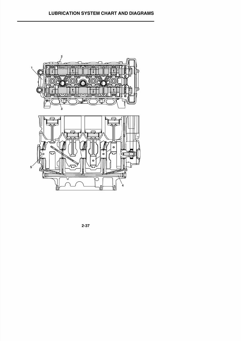
8/21/2019 Fz8 - Service Manual
http://slidepdf.com/reader/full/fz8-service-manual 86/609
LUBRICATION SYSTEM CHART AND DIAGRAMS
1. Cylinder head
2. Exhaust camshaft
3. Intake camshaft
4 M i ll
8/21/2019 Fz8 - Service Manual
http://slidepdf.com/reader/full/fz8-service-manual 87/609
4. Main gallery5. Crankshaft
COOLING SYSTEM DIAGRAMS
EAS20420
COOLING SYSTEM DIAGRAMS
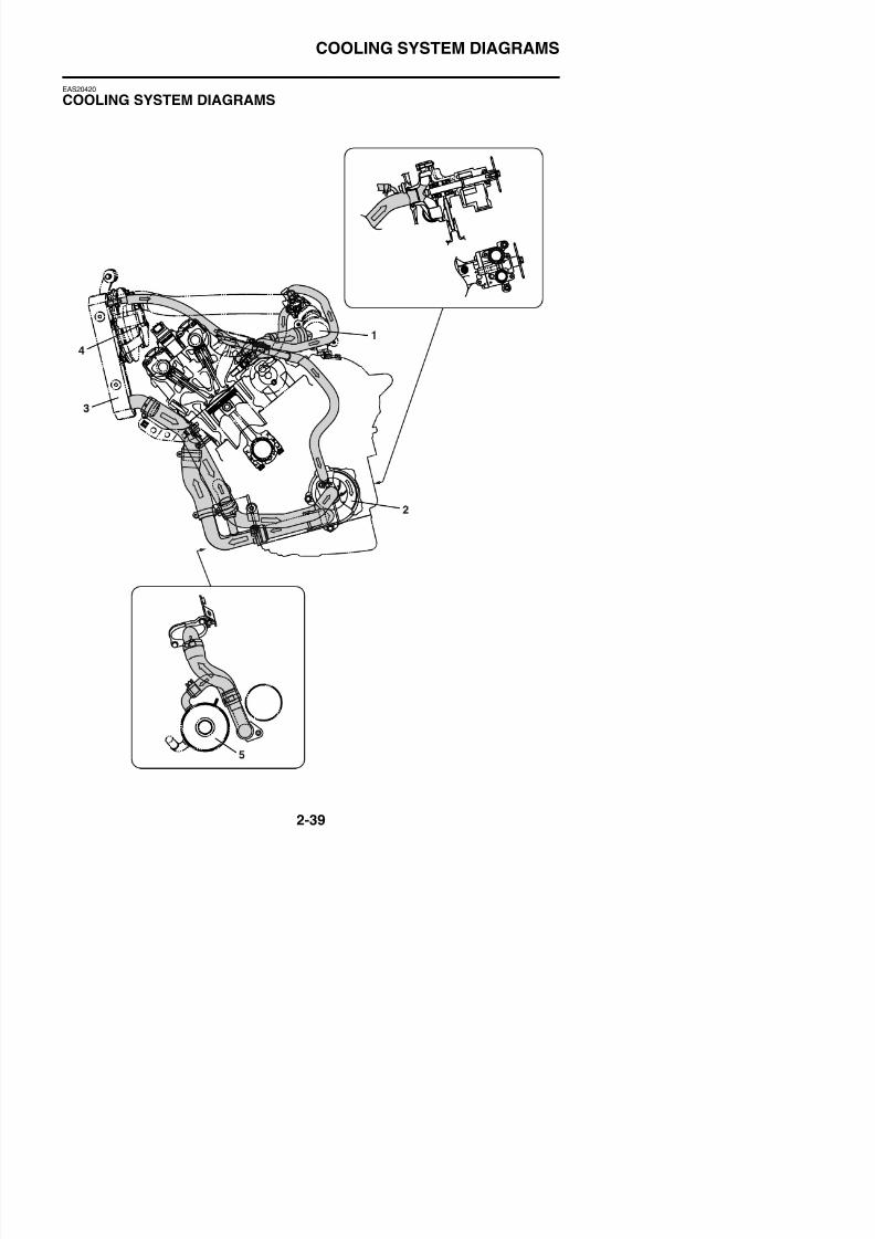
8/21/2019 Fz8 - Service Manual
http://slidepdf.com/reader/full/fz8-service-manual 88/609
COOLING SYSTEM DIAGRAMS
1. Thermostat
2. Water pump
3. Radiator
4 Radiator fan

8/21/2019 Fz8 - Service Manual
http://slidepdf.com/reader/full/fz8-service-manual 89/609
4. Radiator fan5. Oil cooler
COOLING SYSTEM DIAGRAMS
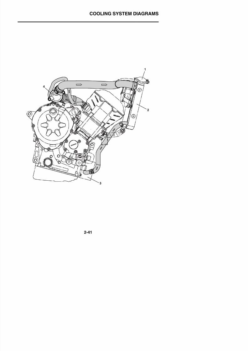
8/21/2019 Fz8 - Service Manual
http://slidepdf.com/reader/full/fz8-service-manual 90/609
COOLING SYSTEM DIAGRAMS
1. Radiator cap
2. Radiator
3. Oil cooler
4 Thermostat

8/21/2019 Fz8 - Service Manual
http://slidepdf.com/reader/full/fz8-service-manual 91/609
4. Thermostat
CABLE ROUTING
EAS20430
CABLE ROUTINGHandlebar (front view)
FZ8NA
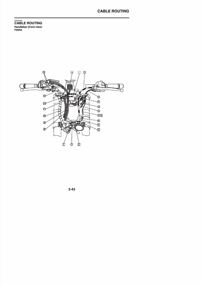
8/21/2019 Fz8 - Service Manual
http://slidepdf.com/reader/full/fz8-service-manual 92/609
FZ8NA
CABLE ROUTING
1. Clutch cable
2. Left handlebar switch lead
3. Main switch lead
4. Immobilizer lead
8/21/2019 Fz8 - Service Manual
http://slidepdf.com/reader/full/fz8-service-manual 93/609
5. Horn lead
6. Lower headlight stay
7. Front wheel sensor lead
8. Throttle cable (return side)
9. Throttle cable (pull side)
10.Brake hose
11.Wire harness
12.Right handlebar switch lead13.Throttle cables
A. Clamp the main switch lead, immobilizerlead, and left handlebar switch lead ateach of the branches and insert the clampinto the upper headlight stay. Face the endof the clamp to the rear of the vehicle.
B. Route the horn lead further inward of the
vehicle than the center of the front fork.The headlight side cover and front forkmust not be pinched.
C. The horn lead and lower headlight staymust not interfere with each other.
D. Clamp the horn lead to the Lower headlightstay and face the head of the clamp to out-side of the vehicle and the end of theclamp to the rear of the vehicle. Cut off theexcess end of the clamp, leaving 2–4 mm
(0.08–0.16 in).E. Insert the bullet terminal of the horn lead in
the direction shown in the illustration.
F. The horn lead should not protrude out.
G. Clamp the wire harness at the branch andinsert it into the upper headlight stay. Facethe end of the clamp to the rear of the vehi-cle.
H. Connect the meter coupler to the meter.
I. To the headlight lead coupler
CABLE ROUTING
Handlebar (front view)FZ8SA
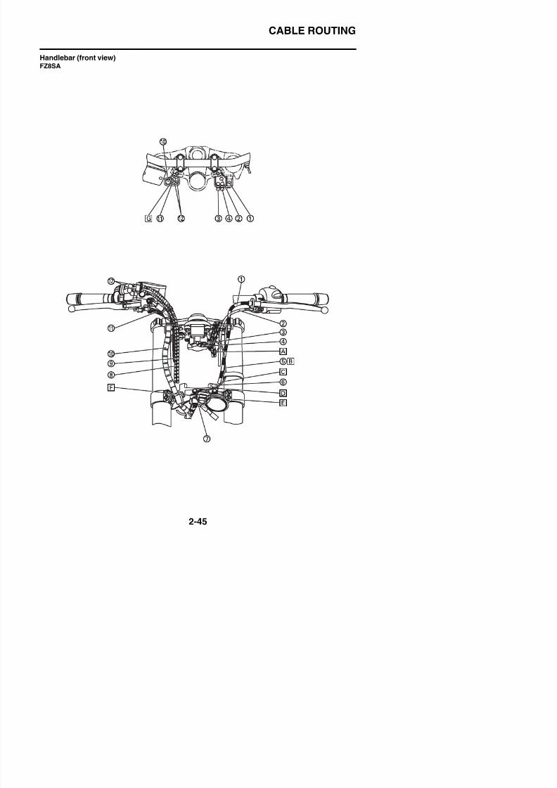
8/21/2019 Fz8 - Service Manual
http://slidepdf.com/reader/full/fz8-service-manual 94/609
CABLE ROUTING
1. Clutch cable
2. Left handlebar switch lead
3. Main switch lead
4. Immobilizer lead5 H l d
8/21/2019 Fz8 - Service Manual
http://slidepdf.com/reader/full/fz8-service-manual 95/609
5. Horn lead
6. Horn bracket
7. Front wheel sensor lead
8. Throttle cable (return side)
9. Throttle cable (pull side)
10.Brake hose
11.Right handlebar switch lead
12.Throttle cables
A. Route the main switch lead and immobi-lizer lead through the cable holder.
B. Route the horn lead further inward of thevehicle than the center of the front fork.
C. The horn lead and lower bracket must notinterfere with each other.
D. Clamp the horn lead to the horn bracket
and face the head of the clamp to outsideof the vehicle and the end of the clamp tothe rear of the vehicle. Cut off the excessend of the clamp, leaving 2–4 mm (0.08–0.16 in).
E. Insert the bullet terminal of the horn lead inthe direction shown in the illustration.
F. The horn lead should not protrude out.
G. Route the brake hose further to the right ofthe vehicle than this wire and route thethrottle cable and right handlebar switchlead further to the left. Route the right han-dlebar switch lead behind the throttle cableon the rear of the vehicle.
CABLE ROUTING
Handlebar (right side view)
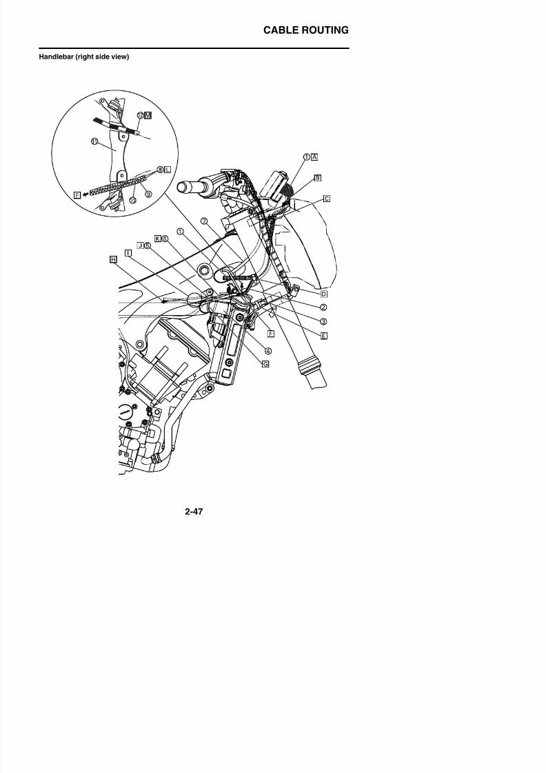
8/21/2019 Fz8 - Service Manual
http://slidepdf.com/reader/full/fz8-service-manual 96/609
CABLE ROUTING
1. Wire harness
2. Throttle cable
3. Front wheel sensor lead
4. Radiator inlet hose5 Right radiator fan motor lead
8/21/2019 Fz8 - Service Manual
http://slidepdf.com/reader/full/fz8-service-manual 97/609
5. Right radiator fan motor lead
6. Coolant reservoir hose
7. Right handlebar switch lead
8. Throttle cables
9. Throttle cable (return side)
10.Throttle cable (pull side)
11.Radiator stay
12.Clutch cable
A. Connect the meter coupler to the meter.
B. To the headlight
C. Install the clamp so that the seating face ispositioned between the claws of the upperheadlight stay.
D. Clamp the wire harness and throttle cablebetween the rubber damper and frame
opening. Face the head of the clamp tooutside of the vehicle and the end of theclamp to the bottom of the vehicle.
E. Clamp the front wheel sensor lead andBrake pipe/joint assembly (hydraulic unit tofront brake calipers). Use the end of theprotector fixing tape of the front wheel sen-sor lead and the tube part of the brakepipe/joint assembly (hydraulic unit to frontbrake calipers) as a guide (permissible
range: (0–10 mm (0–0.39 in)). Whenclamping them, route the front wheel sen-sor lead so that it comes to the top of thevehicle.
F. To the throttle body
G. Clamp the coolant reservoir hose and radi-ator inlet hose and face the head of theclamp to inside of the vehicle and the endof the clamp to the top of the vehicle. Becareful that the end of the clamp does not
protrude out of the radiator upper cover.H. To the wire harness
I. Route the right radiator fan motor leadsuch that it is as taut as possible, within thearea shown in the illustration.
CABLE ROUTING
Engine (right side view)
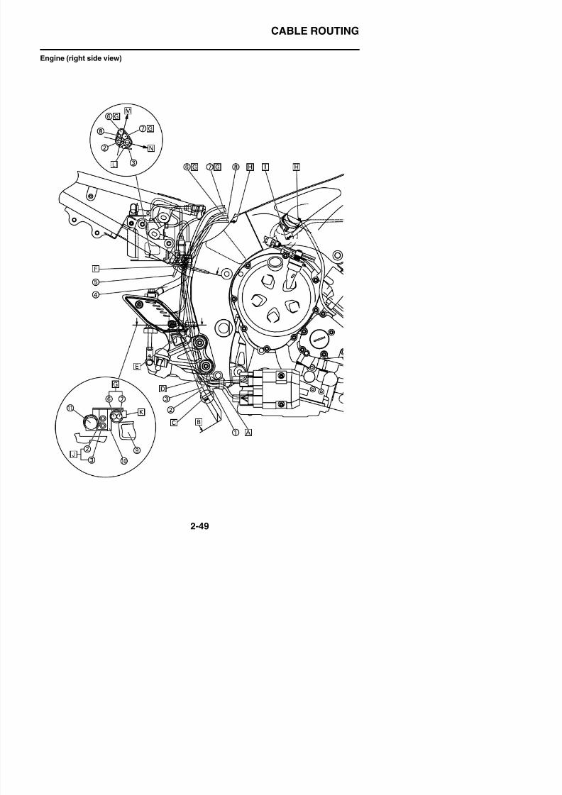
8/21/2019 Fz8 - Service Manual
http://slidepdf.com/reader/full/fz8-service-manual 98/609
CABLE ROUTING
1. Cable guide
2. Fuel tank drain hose
3. Fuel tank breather hose
4. Brake fluid reservoir hose5. Rear wheel sensor lead
8/21/2019 Fz8 - Service Manual
http://slidepdf.com/reader/full/fz8-service-manual 99/609
5. Rear wheel sensor lead
6. AC magneto lead
7. Rectifier/regulator lead
8. Rear brake light switch lead
9. Frame
10.Rear brake light switch stay
11.Rear brake light switch
A. Clamp the AC magneto lead and rectifier/ regulator lead. Insert the clamp into thecable guide so that the clamp openingfaces to the top of the vehicle.
B. For the position of the end of the fuel tankbreather hose, use the end of the fuel tankdrain hose as a guide.
C. Pass the fuel tank breather hose and fueltank drain hose through the cable guide.
The white paint mark on the fuel tank drainhose should be under the cable guide.
D. Route the AC magneto lead and rectifier/ regulator lead further to the front of thevehicle than the cable guide.
E. Route the fuel tank breather hose and fueltank drain hose through the opening of therear brake light switch stay.
F. The clamp position should be inside the
rear frame joint section.G. Order insignificant-AC magneto lead and
rectifier/regulator lead.
H. To the wire harness
I. To the coolant reservoir
J. Order insignificant-fuel tank breather hoseand fuel tank drain hose.
K. Clamp opening faces to the front of thevehicle.
L. Install the clamp, facing the head of theclamp to outside of the vehicle and the endof the clamp to the front of the vehicle.
M. Inside of the vehicle
N Front of the vehicle
CABLE ROUTING
Handlebar (left side view)
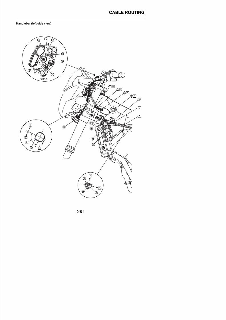
8/21/2019 Fz8 - Service Manual
http://slidepdf.com/reader/full/fz8-service-manual 100/609
CABLE ROUTING
1. Immobilizer lead
2. Main switch lead
3. Left handlebar switch lead
4. Clutch cable5. Clutch cable swaging metal
8/21/2019 Fz8 - Service Manual
http://slidepdf.com/reader/full/fz8-service-manual 101/609
6. Left radiator fan motor lead
7. Water pump breather hose
8. Radiator stay
9. Horn
10.Right handlebar switch lead
11.Meter bracket
12.Brake hose13.Throttle cables
14.Upper bracket
15.Horn lead
A. Order insignificant-immobilizer lead, mainswitch lead and left handlebar switch lead.
B. Route the clutch cable to the radiator stayconcave.
C. Insert the clamp into the frame and clampthe clutch cable. Position the clutch cableswaging metal further to the front of thevehicle than the clamp and face the clampopening to outside of the vehicle.
D. Clamp the clutch cable, left radiator fanmotor lead, and water pump breather hoseand face the head of the clamp to the top ofthe vehicle and the end of the clamp toinside of the vehicle. Use the position of
the cylinder head cover shown in the illus-tration as a guide to install the clamp.
E. 45–65 mm (1.77–2.56 in)
F. Upper side of the vehicle
G. Inside of the vehicle
H. Clamp the horn lead to the front fork andface the head of the clamp to rear of thevehicle and the end of the clamp to theinside of the vehicle.
I. The horn lead should be positioned in the90° area.
J. Outside of the vehicle
CABLE ROUTING
Engine (left side view)
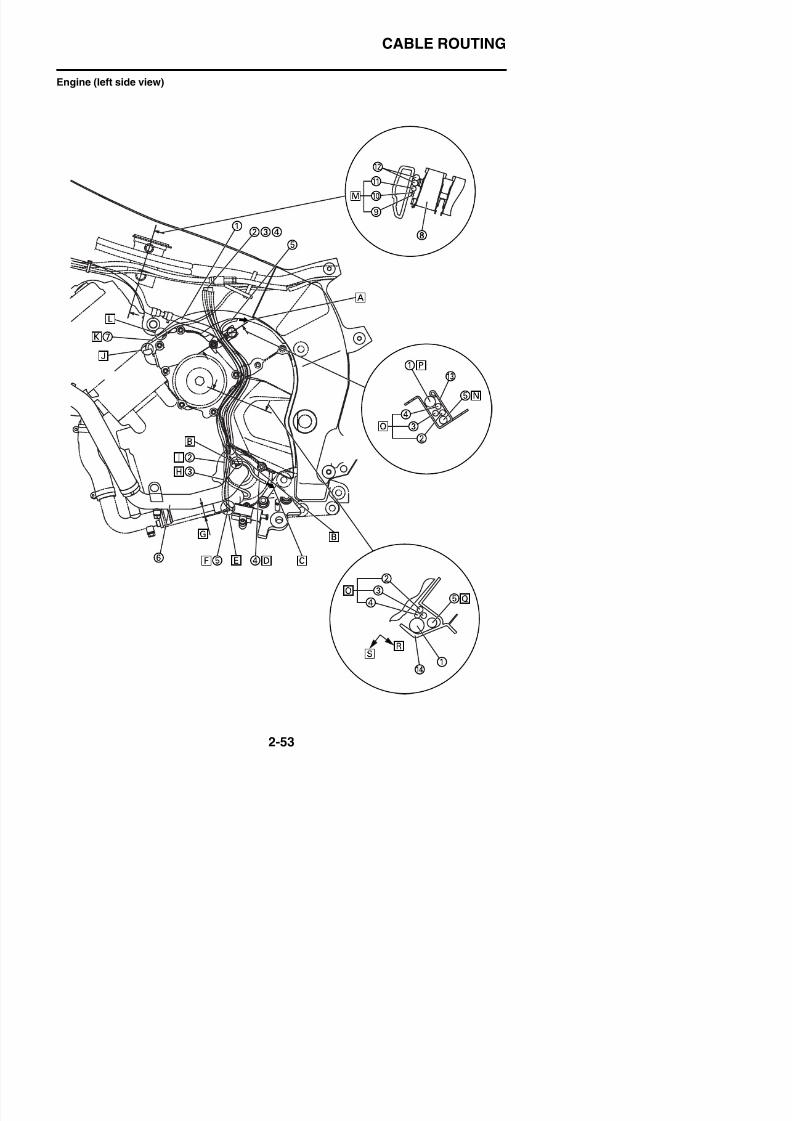
8/21/2019 Fz8 - Service Manual
http://slidepdf.com/reader/full/fz8-service-manual 102/609
CABLE ROUTING
1. Water pump breather hose
2. Oil level switch lead
3. Sidestand switch lead
4. O2 sensor lead5. Coolant reservoir tank drain hose
W i l i
Q. Route the coolant reservoir tank drain hosefurther to the rear of the vehicle than otherhoses and leads.
R. Back of the vehicle
S. Outside of the vehicle
8/21/2019 Fz8 - Service Manual
http://slidepdf.com/reader/full/fz8-service-manual 103/609
6. Water pump inlet pipe
7. AC magneto lead
8. Throttle body
9. Ignition coil sub-wire harness
10.Left radiator fan motor lead
11.Clutch cable
12.Wire harness13.Idle adjust screw holder
14.Drive sprocket cover
A. To the coolant reservoir
B. Route the O2 sensor lead further inward ofthe vehicle than the branch pipe of thewater pump breather hose, then furtherbottom-outward than the water pump
breather hose, and finally toward the top ofthe vehicle as shown in the illustration.
C. To the exhaust
D. Route the O2 sensor lead further to therear of the vehicle than the water pumpinlet pipe.
E. Order insignificant-the positions of the endof the coolant reservoir tank drain hoseand the sidestand switch lead.
F. Route the coolant reservoir tank drain hosefurther to the front of the vehicle than thewater pump breather hose and water pumpinlet pipe.
G. More than 10 mm (0.39 in)
H. Route the sidestand switch lead further tothe front of the vehicle than the water pumpbreather hose and water pump inlet pipe.
I. Route the oil level switch lead further to thefront of the vehicle than the water pump
breather hose and water pump inlet pipe.J. There should be no exposure of bare con-
ductors due to the misalignment of tubes.
K. Route the AC magneto lead further inwardof the vehicle than the water pump
CABLE ROUTING
Rear frame (left side view)
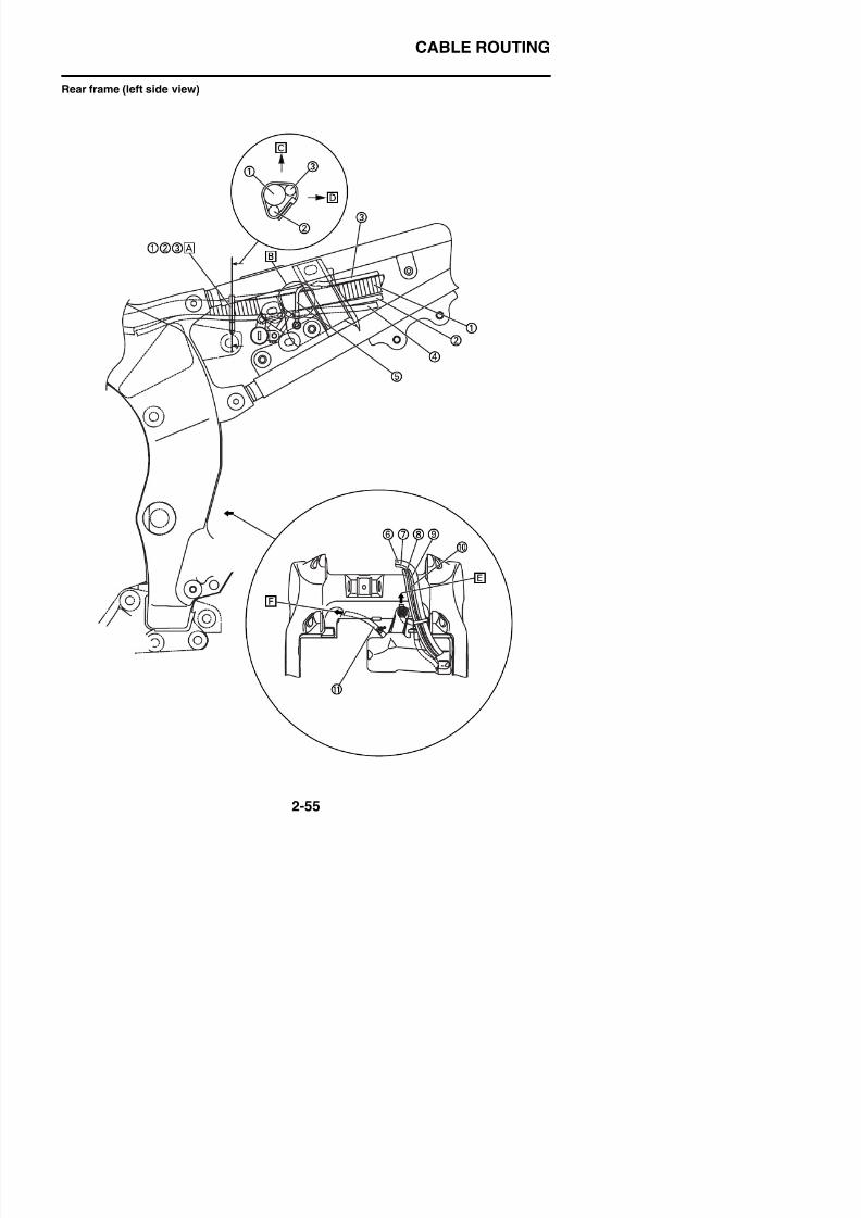
8/21/2019 Fz8 - Service Manual
http://slidepdf.com/reader/full/fz8-service-manual 104/609
CABLE ROUTING
1. Wire harness
2. Starter motor lead
3. Battery negative lead
4. Seat lock cable5. Ground lead
6 Fuel tank drain hose
8/21/2019 Fz8 - Service Manual
http://slidepdf.com/reader/full/fz8-service-manual 105/609
6. Fuel tank drain hose
7. Fuel tank breather hose
8. AC magneto lead
9. Rectifier/regulator lead
10.Rear brake light switch lead
11.Coolant reservoir tank drain hose
A. Clamp the wire harness, starter motorlead, and battery negative lead further tothe front than the branch of the fuse box 2lead. Face the head of the clamp to insideof the vehicle and the end of the clampdown.
B. Route the ground lead between the rearframe bracket and battery box. The groundrivet on the wire harness stem side should
not be caught with the rear frame bracket.C. Upper side of the vehicle
D. Inside of the vehicle
E. To the radiator
F. Atmospheric opening
CABLE ROUTING
Frame (top view)
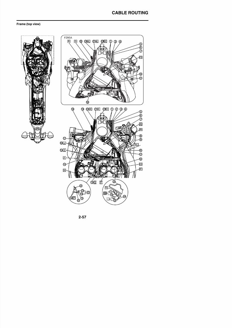
8/21/2019 Fz8 - Service Manual
http://slidepdf.com/reader/full/fz8-service-manual 106/609
CABLE ROUTING
1. Throttle cable
2. Right handlebar switch lead
3. Wire harness
4. Front wheel sensor lead5. Throttle cable (pull side)
6 Throttle cable (return side)
I. Connect the left handlebar switch lead cou-pler and then put the rubber cover of thewire harness.
J. Route the main switch lead coupler
between outside of ECU (engine controlunit) holder and frame so that the whitecoupler comes to the top.
8/21/2019 Fz8 - Service Manual
http://slidepdf.com/reader/full/fz8-service-manual 107/609
6. Throttle cable (return side)
7. Intake air temperature sensor lead
8. Coolant reservoir hose
9. Radiator inlet hose
10.Right handlebar switch lead coupler
11.Front wheel sensor lead coupler
12.Sub-throttle position sensor lead13.Immobilizer lead coupler
14.Air cut-off valve hose
15.Left handlebar switch lead coupler
16.Main switch lead coupler
17.Water pump breather hose
18.ECU (engine control unit)
19.Clutch cable
20.Immobilizer lead21.Left handlebar switch lead
22.Main switch lead
23.Frame
24.ECU (engine control unit) holder
25.Rubber protector
26.Left handlebar switch lead coupler
A. Clamp the wire harness and front wheelsensor lead at the white tape marks andthe right handlebar switch lead at the redtape marks. Face the end of the clamp toinside of the vehicle (Order insignificant).
B. Route the right radiator fan motor leadunder the brake pipe/joint assembly.
C. 10–30 mm (0.39–1.18 in)
D. Check that each lead is routed further out-ward of the vehicle than the throttle body
side cover and then install the air filtercase.
E. Clamp the wire harness and right radiatorfan motor lead, using the position of thethrottle body shown in the illustration as a
p p
K. Order insignificant-immobilizer lead, lefthandlebar switch lead, and main switchlead.
L. Order insignificant-wire harness and immo-bilizer lead.
M. Order insignificant-Right handlebar switch
lead coupler and Front wheel sensor leadcoupler.
N. Route each lead between the frame andECU (engine control unit) holder.
O. Order insignificant-main switch lead andimmobilizer lead.
P. Route the left handlebar switch lead cou-pler under the main switch lead and immo-bilizer lead and between ECU (enginecontrol unit) holder and rubber protector.
Q. Clamp the wire harness, right handlebarswitch lead, and front wheel sensor lead atthe white tape marks and face the end ofthe clamp to inside of the vehicle.
R. Clamp the branch of the wire harness atinside of the radiator stay and face thehead and end of the clamp to the rear ofthe vehicle.
S. Route the main switch lead, immobilizerlead, and left handlebar switch lead abovethe wire harness.
CABLE ROUTING
Frame (top view)
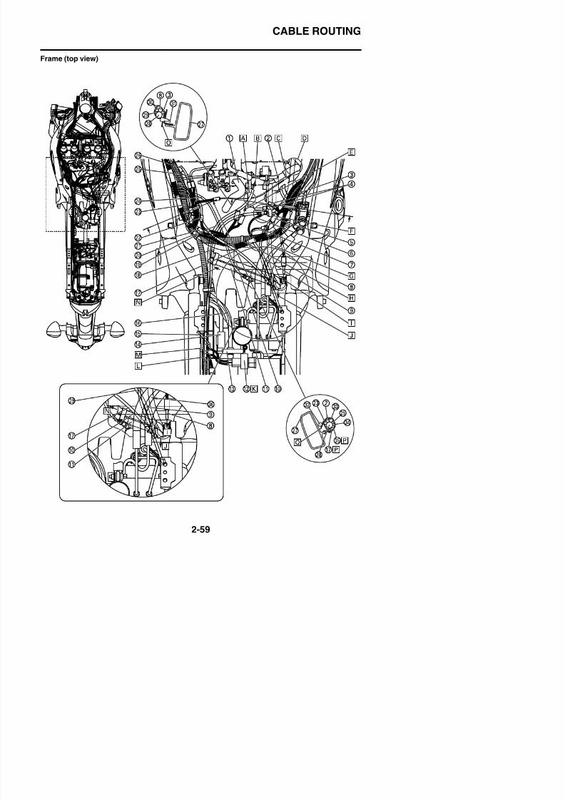
8/21/2019 Fz8 - Service Manual
http://slidepdf.com/reader/full/fz8-service-manual 108/609
CABLE ROUTING
1. Air filter case drain hose
2. Pickup coil lead
3. Right radiator fan motor lead
4. Immobilizer anti-theft alarm coupler5. Rear wheel sensor lead coupler
6. Engine ground lead
K. Insert the main fuse to the battery band.Soapy water can be spread.
L. Route the battery positive lead from insideof the vehicle to under the wire harness. (It
should not be routed above the wire har-ness.)
M. Route the main fuse lead so that the
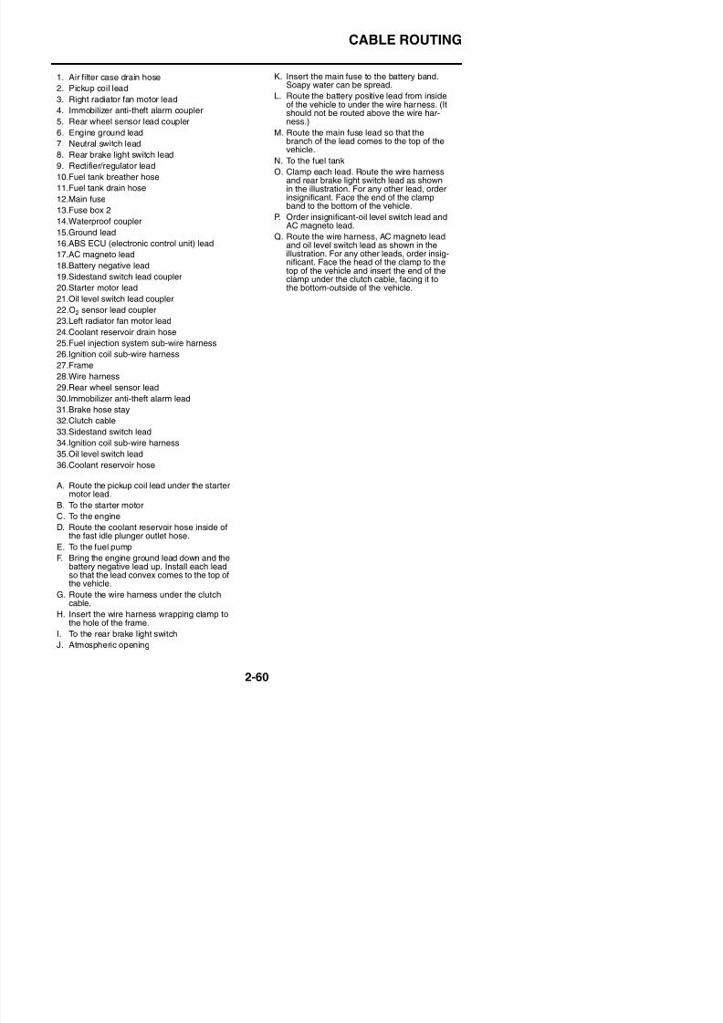
8/21/2019 Fz8 - Service Manual
http://slidepdf.com/reader/full/fz8-service-manual 109/609
g g
7. Neutral switch lead
8. Rear brake light switch lead
9. Rectifier/regulator lead
10.Fuel tank breather hose
11.Fuel tank drain hose
12.Main fuse13.Fuse box 2
14.Waterproof coupler
15.Ground lead
16.ABS ECU (electronic control unit) lead
17.AC magneto lead
18.Battery negative lead
19.Sidestand switch lead coupler
20.Starter motor lead21.Oil level switch lead coupler
22.O2 sensor lead coupler
23.Left radiator fan motor lead
24.Coolant reservoir drain hose
25.Fuel injection system sub-wire harness
26.Ignition coil sub-wire harness
27.Frame
28.Wire harness29.Rear wheel sensor lead
30.Immobilizer anti-theft alarm lead
31.Brake hose stay
32.Clutch cable
33.Sidestand switch lead
34.Ignition coil sub-wire harness
35.Oil level switch lead
36.Coolant reservoir hose
A. Route the pickup coil lead under the startermotor lead.
B To the starter motor
branch of the lead comes to the top of thevehicle.
N. To the fuel tank
O. Clamp each lead. Route the wire harnessand rear brake light switch lead as shownin the illustration. For any other lead, order
insignificant. Face the end of the clampband to the bottom of the vehicle.
P. Order insignificant-oil level switch lead andAC magneto lead.
Q. Route the wire harness, AC magneto leadand oil level switch lead as shown in theillustration. For any other leads, order insig-nificant. Face the head of the clamp to thetop of the vehicle and insert the end of theclamp under the clutch cable, facing it to
the bottom-outside of the vehicle.
CABLE ROUTING
Frame (top view)
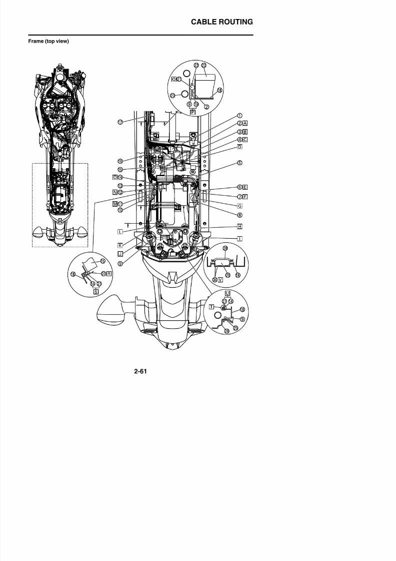
8/21/2019 Fz8 - Service Manual
http://slidepdf.com/reader/full/fz8-service-manual 110/609
CABLE ROUTING
1. Atmospheric pressure sensor
2. Battery positive lead
3. Radiator fan motor relay
4. Fuse box 15. Lean angle sensor
6. Right turn signal light lead
K. The ABS check coupler should not coverthe top of the bolt.
L. Route the tail/brake light lead and rear leftturn signal light lead between the ribs of
the battery box.M. Route the tail/brake light lead coupler
under the headlight relay.
8/21/2019 Fz8 - Service Manual
http://slidepdf.com/reader/full/fz8-service-manual 111/609
7. License plate light lead
8. Turn signal/hazard relay
9. Seat lock cable
10.Headlight relay
11.Tail/brake light coupler
12.ABS test coupler13.ABS test coupler connector
14.Left turn signal light lead
15.Starting circuit cut-off relay
16.Starter relay
17.ABS fuse
18.Battery box
19.Starter motor lead
20.Rear frame21.Wire harness
22.Battery negative lead
23.Battery
24.Lean angle sensor lead
25.Mudguard
26.Rear fender
27.Tail/brake light lead
28.Tool band29.Tool
30.ABS test coupler lead
A. Route the battery positive lead under eachrelay.
B. For the radiator fan motor relay, connectthe coupler and then put the rubber coverof the wire harness.
C. Route the fuse box 1 lead under the radia-tor fan motor relay.
D. Route the battery positive lead under thefuse box 1 lead.
E Connect the connectors of the green tube
N. Slide the rubber cover over the ABS checkcoupler, double-up by folding the coupler,and then route the coupler under the tooland along the left wall of the battery box.
O. Connect the connectors of the red tubeand brown lead.
P. Order insignificant-starter motor lead andseatlock cable.
Q. Push the wire harness firmly to the end.
R. Route the lean angle sensor lead on thetop of the vehicle.
S. Order insignificant-wire harness and leftturn signal light lead.
T. Route the tail/brake light lead and rear leftturn signal light lead between the ribs of
the battery box.U. Order insignificant-tail/brake light lead andrear left turn signal light lead.
V. Route the ABS check coupler lead underthe tool and then fix it with the tool band.
CABLE ROUTING
Fuel tank (left and bottom view)
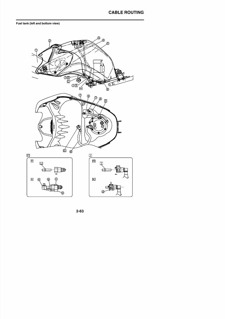
8/21/2019 Fz8 - Service Manual
http://slidepdf.com/reader/full/fz8-service-manual 112/609
CABLE ROUTING
1. Frame
2. Fuel tank cover
3. Fuel tank breather hose
4. Fuel tank drain hose5. Fuel tank
6. Fuel pump
7 Clip
8/21/2019 Fz8 - Service Manual
http://slidepdf.com/reader/full/fz8-service-manual 113/609
7. Clip
8. Fuel hose
9. Fuel hose connector cover
A. Install the fuel tank drain hose with thewhite paint marks facing to the left of the
vehicle.B. For the knob of the clip, any direction is
acceptable. The clip should not be run ontothe spool.
C. Install the fuel tank breather hose with theyellow paint marks facing to the left of thevehicle.
D. Pass the fuel tank drain hose through thefuel tank bracket clamp. There should be
no bend of the hose between the fuel tanknipple and clamp.
E. Fit the black double lock side to the engineside.
F. Fuel pump side
G. Insert the connector until the click sound isheard and check that the connector doesnot come off. Make sure that no foreignmatter is caught in the sealing section. (It isprohibited to wear the cotton work gloves
or equivalent coverings.)H. After item “G” mentioned above is finished,
check that the fuel hose connector cover isinserted from the down side “a”, “b” and “c”sections are perfectly equipped.
I. This part works as a dropout stopper
J. Fuel injector side
K. After Step “G” as above is finished, checkthat the connector is completely attached
by sliding the double lock (black part) “d”on the connector as shown in the illustra-tion and seeing if it touches firmly or not.
CABLE ROUTING
Front brake (right side view)
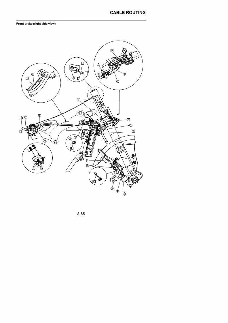
8/21/2019 Fz8 - Service Manual
http://slidepdf.com/reader/full/fz8-service-manual 114/609
CABLE ROUTING
1. Brake hose (hydraulic unit to front brakecalipers)
2. Brake hose (front brake master cylinder tohydraulic unit)
3. Front wheel sensor lead4. Front wheel sensor lead guide
5. Front wheel sensor lead holder
8/21/2019 Fz8 - Service Manual
http://slidepdf.com/reader/full/fz8-service-manual 115/609
6. Brake pipe/joint assembly (front brakemaster cylinder to hydraulic unit)
7. Brake pipe/joint assembly (hydraulic unit tofront brake calipers)
8. Front brake master cylinder
A. Install the brake hose, pushing projectionagainst the lower headlight stay (FZ8NA)or horn bracket (FZ8SA).
B. Install the metal fitting of the front brakehose (hydraulic unit to front brake calipers),pushing projection to the positioning stop-per of the brake caliper.
C. Install the clamp so that the distance fromthe clamp lower surface to the end of the
brake hose offset bracket may be 30–50mm (1.18–1.97 in).The front wheel sensor lead must be posi-tioned at the outer front of the vehicle tothe brake hose.
D. Install the connector metal fittings of thebrake hose (hydraulic unit to front brakecalipers) and front brake hose (front brakemaster cylinder to hydraulic unit), pushingagainst each other.
E. Install the block metal fitting of the brakehose (hydraulic unit to front brake calipers),pushing projection to the stopper.
F. Align the notch of the horn with the projec-tion of the lower headlight stay (FZ8NA) orhorn bracket (FZ8SA).
G. Install the brake hose (hydraulic unit tofront brake calipers) and brake hose (frontbrake master cylinder to hydraulic unit),pushing them to the stopper of the front
brake hose bracket.H. A parallel line to the front brake master cyl-
inder ceiling surface
I. 30°–40°
CABLE ROUTING
Front brake (left side)
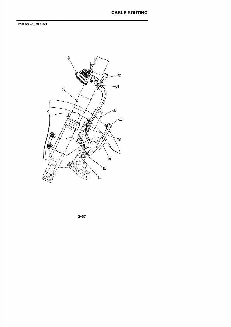
8/21/2019 Fz8 - Service Manual
http://slidepdf.com/reader/full/fz8-service-manual 116/609
CABLE ROUTING
1. Front fork
2. Horn
3. Under bracket
4. Brake hose holder
A. Install the clamp so that the distance fromthe clamp upper surface to the end of thebrake hose protector may be 0 10 mm (0
8/21/2019 Fz8 - Service Manual
http://slidepdf.com/reader/full/fz8-service-manual 117/609
brake hose protector may be 0–10 mm (0–0.39 in). The front wheel sensor lead mustbe positioned at the outer rear of the vehi-cle to the brake hose.
B. Install the clamp so that the distance fromthe clamp lower surface to the end of the
brake hose grommet may be 60–80 mm(2.36–3.15 in). The front wheel sensor leadmust be positioned at the outside of thevehicle to the brake hose.
C. Put the front wheel sensor lead and thebrake hose through. The front wheel sen-sor lead must be positioned at the upperside of the vehicle to the brake hose.
D. Install the clamp so that the distance fromthe clamp lower surface to the end of the
brake hose offset bracket may be 30–50mm (1.18–1.97 in). The front wheel sensorlead must be positioned at the outer frontof the vehicle to the brake hose.
E. Install the metal fitting of the front brakehose (hydraulic unit to front brake calipers),pushing it to the positioning stopper of thebrake caliper.
F. Install the metal fitting stopper pins of thefront brake hose, pushing against each
other.
CABLE ROUTING
Rear brake
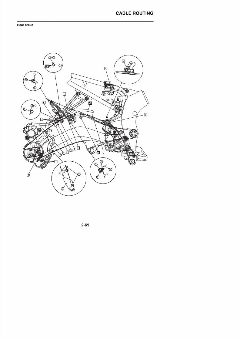
8/21/2019 Fz8 - Service Manual
http://slidepdf.com/reader/full/fz8-service-manual 118/609
CABLE ROUTING
1. Brake hose (hydraulic unit to rear brakecaliper)
2. Rear wheel sensor lead
3. Rear wheel sensor
4. Clamp
5. Swingarm
6. Rear fender
8/21/2019 Fz8 - Service Manual
http://slidepdf.com/reader/full/fz8-service-manual 119/609
A. Install the clip knob so that it faces to theoutside of the vehicle as shown in the illus-tration.
B. Face the clamp opening to the outside ofthe vehicle.
C. Route the rear wheel sensor lead inside ofthe vehicle.
D. Face the clamp opening to the bottom ofthe vehicle.
E. Clamp the brake hose and rear wheel sen-sor lead. Route the rear wheel sensor leadabove the brake hose and face the clampopening to the bottom of the vehicle.
F. The clamp position should be in the range
of 30–40 mm (1.18–1.57 in) from the endof the grommet of the brake hose.
G. Insert the brake hose holder claw firmlyinto the swingarm.
H. 10–20 mm (0.39–0.79 in)
I. Insert the holder of the rear wheel sensorbracket between the ribs behind the rearwheel sensor protector.
J. Route the rear wheel sensor lead along the
brake hose grommet and then clamp it.K. 140–150 mm (5.51–5.91 in) (Clamp posi-
tion of the rear wheel sensor lead)
L. 213–233 mm (8.39–9.17 in)
M. 60–80 mm (2.36–3.15 in)
N. Install the metal fitting of the brake hose(rear brake master cylinder to hydraulicunit), pushing projection in the directionshown in the illustration.
O. Route the rear wheel sensor lead to the topof the vehicle.
P. Inside of the vehicle
Q. Install so that the smaller grommet comest th t id f th hi l
CABLE ROUTING
Hydraulic unit (top view)
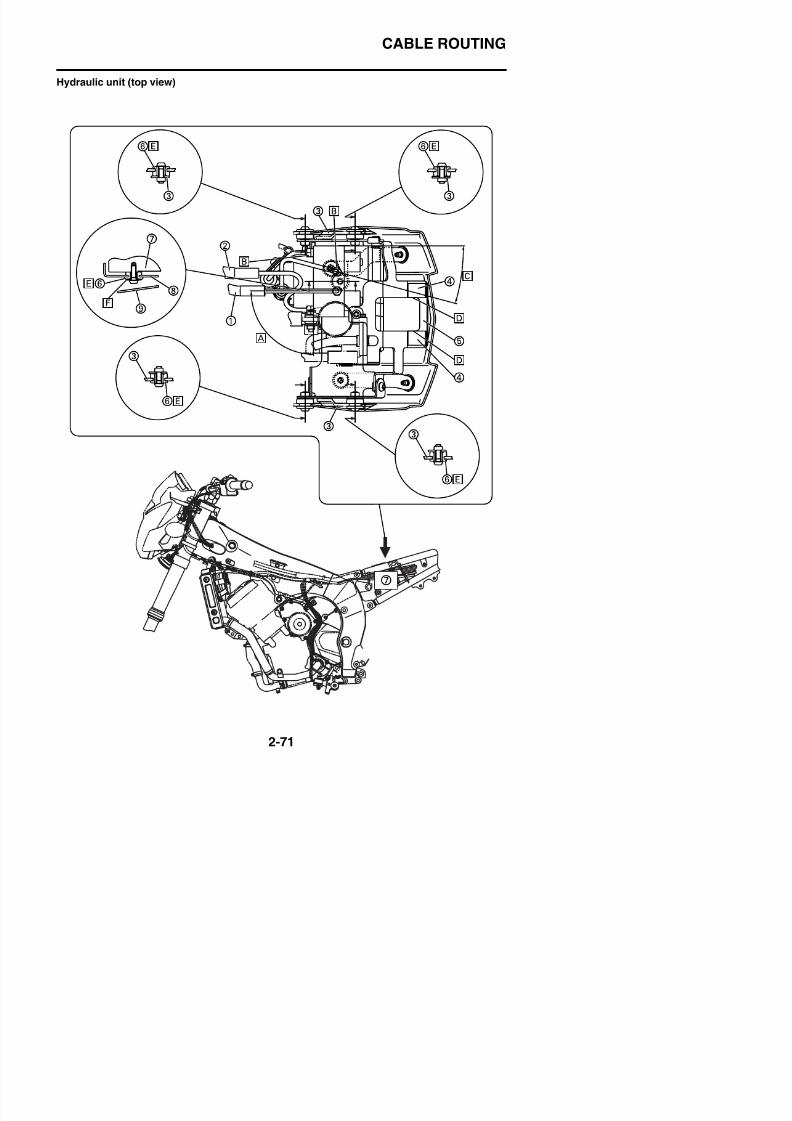
8/21/2019 Fz8 - Service Manual
http://slidepdf.com/reader/full/fz8-service-manual 120/609
CABLE ROUTING
1. Brake pipe/joint assembly (front brakemaster cylinder to hydraulic unit)
2. Brake pipe/joint assembly (hydraulic unit tofront brake calipers)
3. Rear frame4. Damper
5. Upper hydraulic unit bracket
6. Grommet
8/21/2019 Fz8 - Service Manual
http://slidepdf.com/reader/full/fz8-service-manual 121/609
6 G o e
7. Hydraulic unit
8. Lower hydraulic unit bracket
9. Under cover
A. Install the brake pipe/joint assembly(hydraulic unit to front brake calipers) in thearea between 88°–92°.
B. Clamp the brake hose (hydraulic unit torear brake caliper) and brake hose (rearbrake master cylinder to hydraulic unit) tothe brake hose holder and then tighten thehoses.
C. 15°
D. Affix the damper, aligning the end of thedamper with the end of the upper hydraulicunit bracket.
E. Soapy water may be applied during instal-lation.
F. Install the collar from outside of the lowerhydraulic unit bracket.
CABLE ROUTING
Hydraulic unit (front view)
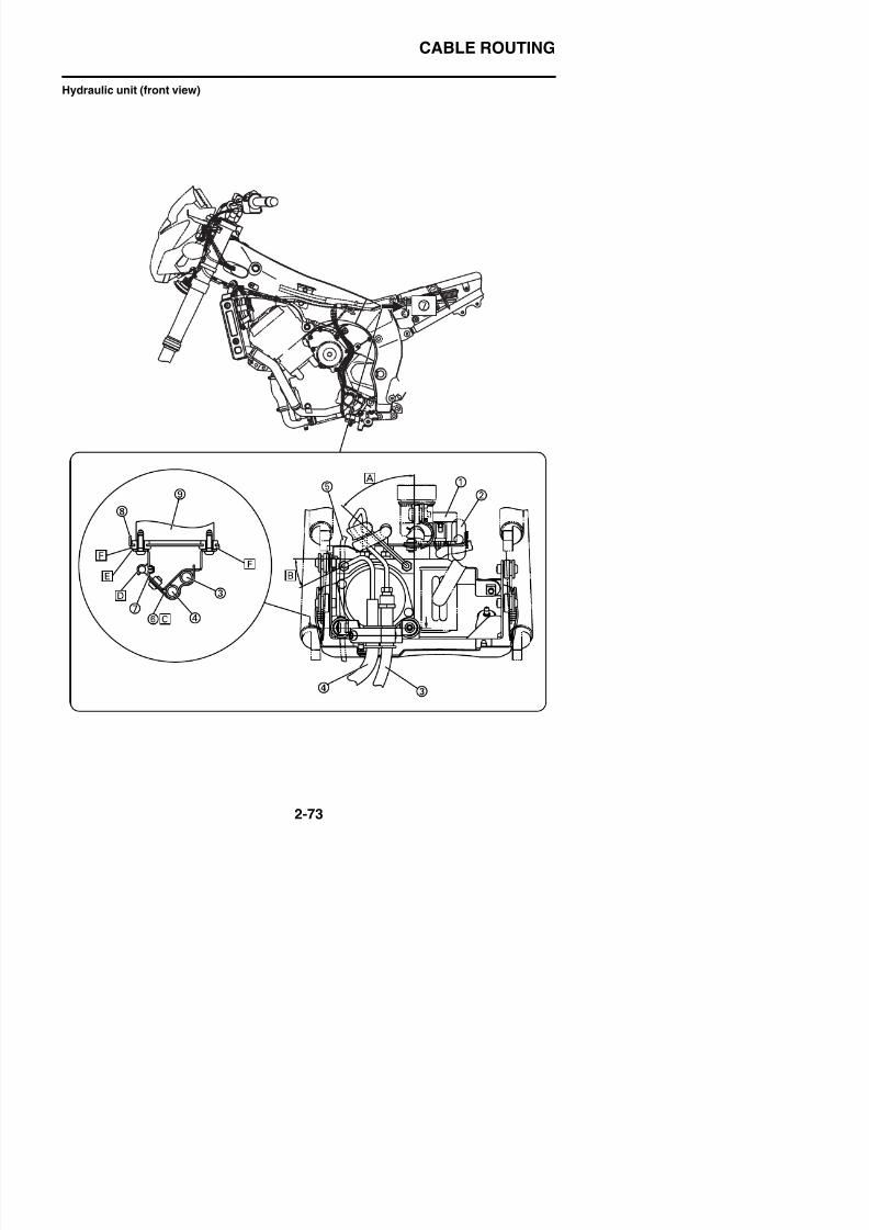
8/21/2019 Fz8 - Service Manual
http://slidepdf.com/reader/full/fz8-service-manual 122/609
CABLE ROUTING
1. Fuse box 2
2. Waterproof coupler
3. Brake hose (hydraulic unit to rear brakecaliper)
4. Brake hose (rear brake master cylinder tohydraulic unit)
5. Rear wheel sensor lead
6. Rear brake hose holder
8/21/2019 Fz8 - Service Manual
http://slidepdf.com/reader/full/fz8-service-manual 123/609
7. Rear brake hose guide
8. Lower hydraulic unit bracket
9. Hydraulic unit
A. Install the brake pipe/joint assembly(hydraulic unit to front brake calipers) in thearea between 45°–49°.
B. 26°
C. Insert the claw of the rear brake hoseholder firmly into the hole of the rear brakehose guide.
D. Insert the clamp opening, facing the open-ing to the front of the vehicle as shown inthe illustration.
E. Install the collar from outside of the lowerhydraulic unit bracket.
F. Soapy water may be applied during instal-lation.
CABLE ROUTING
Hydraulic unit (left side view)
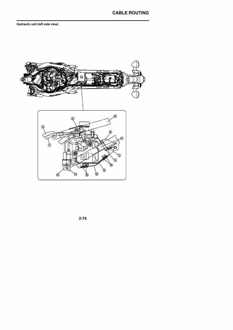
8/21/2019 Fz8 - Service Manual
http://slidepdf.com/reader/full/fz8-service-manual 124/609
CABLE ROUTING
1. Brake pipe/joint assembly (front brakemaster cylinder to hydraulic unit)
2. Brake pipe/joint assembly (hydraulic unit tofront brake calipers)
3. Brake fluid reservoir tank stay4. Rear frame
5. Battery box
6. Upper hydraulic unit bracket
D
8/21/2019 Fz8 - Service Manual
http://slidepdf.com/reader/full/fz8-service-manual 125/609
7. Damper
8. Quick fastener
9. Lower hydraulic unit bracket
10.Under cover
11.Brake hose (hydraulic unit to rear brakecaliper)
12.Brake hose (rear brake master cylinder tohydraulic unit)
A. Affix the damper, aligning the end of thedamper with the end of the bending part ofthe upper hydraulic unit bracket.
CABLE ROUTING

8/21/2019 Fz8 - Service Manual
http://slidepdf.com/reader/full/fz8-service-manual 126/609
PERIODIC CHECKS AND ADJUSTMENTS
PERIODIC MAINTENANCE .........................................................................3-1
INTRODUCTION ....................................................................................3-1PERIODIC MAINTENANCE CHART FOR THE EMISSIONCONTROL SYSTEM...............................................................................3-1GENERAL MAINTENANCE AND LUBRICATION CHART.....................3-2CHECKING THE FUEL LINE 3 4
8/21/2019 Fz8 - Service Manual
http://slidepdf.com/reader/full/fz8-service-manual 127/609
3
CHECKING THE FUEL LINE .................................................................3-4CHECKING THE SPARK PLUGS...........................................................3-4ADJUSTING THE VALVE CLEARANCE ................................................3-5ADJUSTING THE ENGINE IDLING SPEED .......................................... 3-8
SYNCHRONIZING THE THROTTLE BODIES ....................................... 3-9CHECKING THE THROTTLE BODY JOINTS ......................................3-10ADJUSTING THE EXHAUST GAS VOLUME.......................................3-11CHECKING THE EXHAUST SYSTEM.................................................3-11CHECKING THE AIR INDUCTION SYSTEM....................................... 3-12CHECKING THE CRANKCASE BREATHER HOSE............................3-12REPLACING THE AIR FILTER ELEMENT...........................................3-12ADJUSTING THE CLUTCH CABLE FREE PLAY ................................ 3-13
CHECKING THE BRAKE OPERATION................................................3-14CHECKING THE BRAKE FLUID LEVEL..............................................3-14ADJUSTING THE FRONT DISC BRAKE .............................................3-15CHECKING THE FRONT BRAKE PADS..............................................3-15ADJUSTING THE REAR DISC BRAKE ...............................................3-15CHECKING THE REAR BRAKE PADS ................................................3-16BLEEDING THE HYDRAULIC BRAKE SYSTEM.................................3-16CHECKING THE FRONT BRAKE HOSES...........................................3-17
CHECKING THE REAR BRAKE HOSE ...............................................3-17CHECKING THE WHEELS .................................................................. 3-18CHECKING THE TIRES ....................................................................... 3-18CHECKING THE WHEEL BEARINGS .................................................3-19CHECKING THE SWINGARM OPERATION........................................3-19ADJUSTING THE DRIVE CHAIN SLACK ............................................3-19LUBRICATING THE DRIVE CHAIN......................................................3-20CHECKING AND ADJUSTING THE STEERING HEAD ...................... 3-21
LUBRICATING THE BRAKE LEVER....................................................3-22LUBRICATING THE CLUTCH LEVER..................................................3-22LUBRICATING THE PEDAL .................................................................3-22ADJUSTING THE SHIFT PEDAL 3 22
CHECKING THE FRONT BRAKE LIGHT SWITCH ............................. 3-29ADJUSTING THE REAR BRAKE LIGHT SWITCH ..............................3-29CHECKING AND LUBRICATING THE CABLES .................................. 3-29ADJUSTING THE THROTTLE CABLE FREE PLAY ............................ 3-30
CHECKING AND CHARGING THE BATTERY.....................................3-30CHECKING THE FUSES......................................................................3-30REPLACING THE HEADLIGHT BULB (FZ8NA) .................................. 3-30REPLACING THE HEADLIGHT BULBS (FZ8SA) ................................ 3-32ADJUSTING THE HEADLIGHT BEAM (FZ8NA) 3 33
8/21/2019 Fz8 - Service Manual
http://slidepdf.com/reader/full/fz8-service-manual 128/609
ADJUSTING THE HEADLIGHT BEAM (FZ8NA)..................................3-33ADJUSTING THE HEADLIGHT BEAMS (FZ8SA)................................3-33

8/21/2019 Fz8 - Service Manual
http://slidepdf.com/reader/full/fz8-service-manual 129/609
PERIODIC MAINTENANCE
EAS20450
PERIODIC MAINTENANCE
EAS20460
INTRODUCTIONThis chapter includes all information necessary to perform recommended checks and adjustments.If followed, these preventive maintenance procedures will ensure more reliable vehicle operation, alonger service life and reduce the need for costly overhaul work. This information applies to vehiclesalready in service as well as to new vehicles that are being prepared for sale. All service techniciansh ld b f ili ith thi ti h t
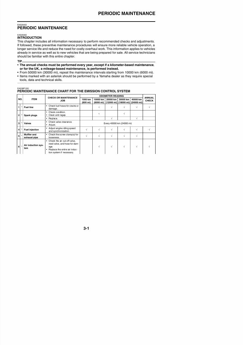
8/21/2019 Fz8 - Service Manual
http://slidepdf.com/reader/full/fz8-service-manual 130/609
should be familiar with this entire chapter.
TIP
• The annual checks must be performed every year, except if a kilometer-based maintenance,
or for the UK, a mileage-based maintenance, is performed instead.• From 50000 km (30000 mi), repeat the maintenance intervals starting from 10000 km (6000 mi).• Items marked with an asterisk should be performed by a Yamaha dealer as they require special
tools, data and technical skills.
EAS39P1301
PERIODIC MAINTENANCE CHART FOR THE EMISSION CONTROL SYSTEM
NO. ITEM
CHECK OR MAINTENANCE
JOB
ODOMETER READINGANNUAL
CHECK1000 km(600 mi)
10000 km(6000 mi)
20000 km(12000 mi)
30000 km(18000 mi)
40000 km(24000 mi)
1 * Fuel line• Check fuel hoses for cracks or
damage. √ √ √ √ √
2 * Spark plugs
• Check condition.
• Clean and regap. √ √
• Replace. √ √
3 * Valves• Check valve clearance.
• Adjust.Every 40000 km (24000 mi)
4 * Fuel injection• Adjust engine idling speed
and synchronization. √ √ √ √ √ √
5 *Muffler and
exhaust pipe
• Check the screw clamp(s) for
looseness. √ √ √ √ √
6 *Air induction sys-
tem
• Check the air cut-off valve,
reed valve, and hose for dam-
age.
• Replace the entire air induc-
tion system if necessary.
√ √ √ √ √
PERIODIC MAINTENANCE
EAS39P1302
GENERAL MAINTENANCE AND LUBRICATION CHART
NO. ITEMCHECK OR MAINTENANCE
JOB
ODOMETER READINGANNUAL
CHECK1000 km
(600 mi)
10000 km
(6000 mi)
20000 km
(12000 mi)
30000 km
(18000 mi)
40000 km
(24000 mi)1 Air filter element • Replace. √
2 Clutch• Check operation.
• Adjust. √ √ √ √ √
3 * Front brake
• Check operation, fluid level
and vehicle for fluid leakage. √ √ √ √ √ √
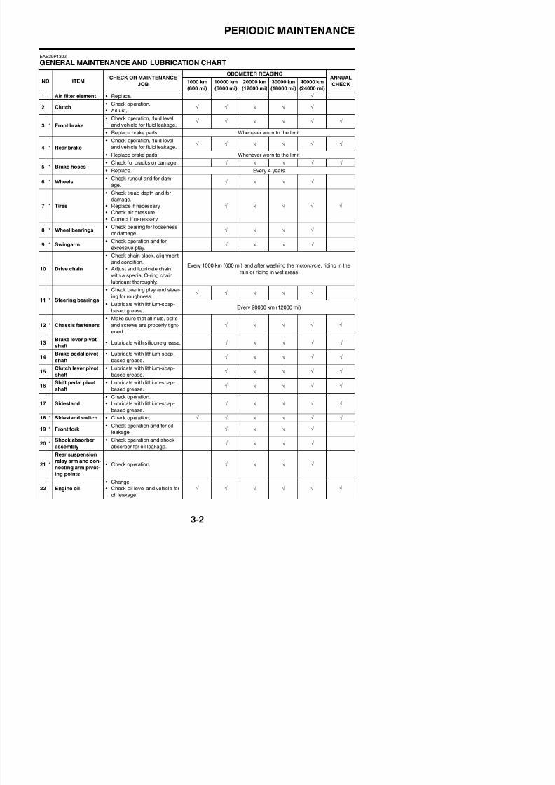
8/21/2019 Fz8 - Service Manual
http://slidepdf.com/reader/full/fz8-service-manual 131/609
3 Front brake g
• Replace brake pads. Whenever worn to the limit
4 * Rear brake
• Check operation, fluid level
and vehicle for fluid leakage. √ √ √ √ √ √
• Replace brake pads. Whenever worn to the limit
5 * Brake hoses• Check for cracks or damage. √ √ √ √ √
• Replace. Every 4 years
6 * Wheels• Check runout and for dam-
age. √ √ √ √
7 * Tires
• Check tread depth and for
damage.
• Replace if necessary.
• Check air pressure.
• Correct if necessary.
√ √ √ √ √
8 * Wheel bearings • Check bearing for loosenessor damage.
√ √ √ √
9 * Swingarm• Check operation and for
excessive play. √ √ √ √
10 Drive chain
• Check chain slack, alignment
and condition.
• Adjust and lubricate chain
with a special O-ring chain
lubricant thoroughly.
Every 1000 km (600 mi) and after washing the motorcycle, riding in the
rain or riding in wet areas
11 * Steering bearings
• Check bearing play and steer-
ing for roughness. √ √ √ √ √
• Lubricate with lithium-soap-
based grease.Every 20000 km (12000 mi)
12 * Chassis fasteners
• Make sure that all nuts, bolts
and screws are properly tight-
ened.
√ √ √ √ √
13Brake lever pivot
shaft• Lubricate with silicone grease. √ √ √ √ √
14Brake pedal pivot
shaft
• Lubricate with lithium-soap-
based grease. √ √ √ √ √
15Clutch lever pivot
shaft
• Lubricate with lithium-soap-
based grease. √ √ √ √ √
16Shift pedal pivot
shaft
• Lubricate with lithium-soap-
based grease √ √ √ √ √
PERIODIC MAINTENANCE
23Engine oil filter
cartridge• Replace. √ √ √
24 * Cooling system
• Check coolant level and vehi-
cle for coolant leakage. √ √ √ √ √
• Change. Every 3 years
25 *Front and rear
brake switches• Check operation. √ √ √ √ √ √
NO. ITEMCHECK OR MAINTENANCE
JOB
ODOMETER READINGANNUAL
CHECK1000 km
(600 mi)
10000 km
(6000 mi)
20000 km
(12000 mi)
30000 km
(18000 mi)
40000 km
(24000 mi)
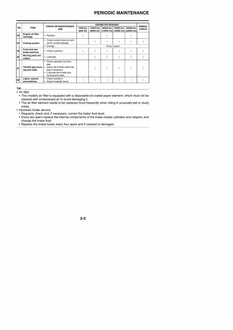
8/21/2019 Fz8 - Service Manual
http://slidepdf.com/reader/full/fz8-service-manual 132/609
TIP
• Air filter
• This model’s air filter is equipped with a disposable oil-coated paper element, which must not becleaned with compressed air to avoid damaging it.
• The air filter element needs to be replaced more frequently when riding in unusually wet or dustyareas.
• Hydraulic brake service• Regularly check and, if necessary, correct the brake fluid level.• Every two years replace the internal components of the brake master cylinders and calipers, and
change the brake fluid.
• Replace the brake hoses every four years and if cracked or damaged.
26Moving parts and
cables• Lubricate. √ √ √ √ √
27 * Throttle grip hous-ing and cable
• Check operation and free
play.
• Adjust the throttle cable freeplay if necessary.
• Lubricate the throttle grip
housing and cable.
√ √ √ √ √
28 *Lights, signals
and switches
• Check operation.
• Adjust headlight beam. √ √ √ √ √ √
PERIODIC MAINTENANCE
EAS21030
CHECKING THE FUEL LINEThe following procedure applies to all of thefuel, vacuum and breather hoses.
1. Remove:• Rider seatRefer to “GENERAL CHASSIS” on page4-1.
• Fuel tankR f t “FUEL TANK” 7 1
EAS20680
CHECKING THE SPARK PLUGSThe following procedure applies to all of thespark plugs.
1. Remove:• Inner panel/side panel/front cowling sidepanel (FZ8SA)Refer to “GENERAL CHASSIS” on page
4-1.R di t (FZ8NA)
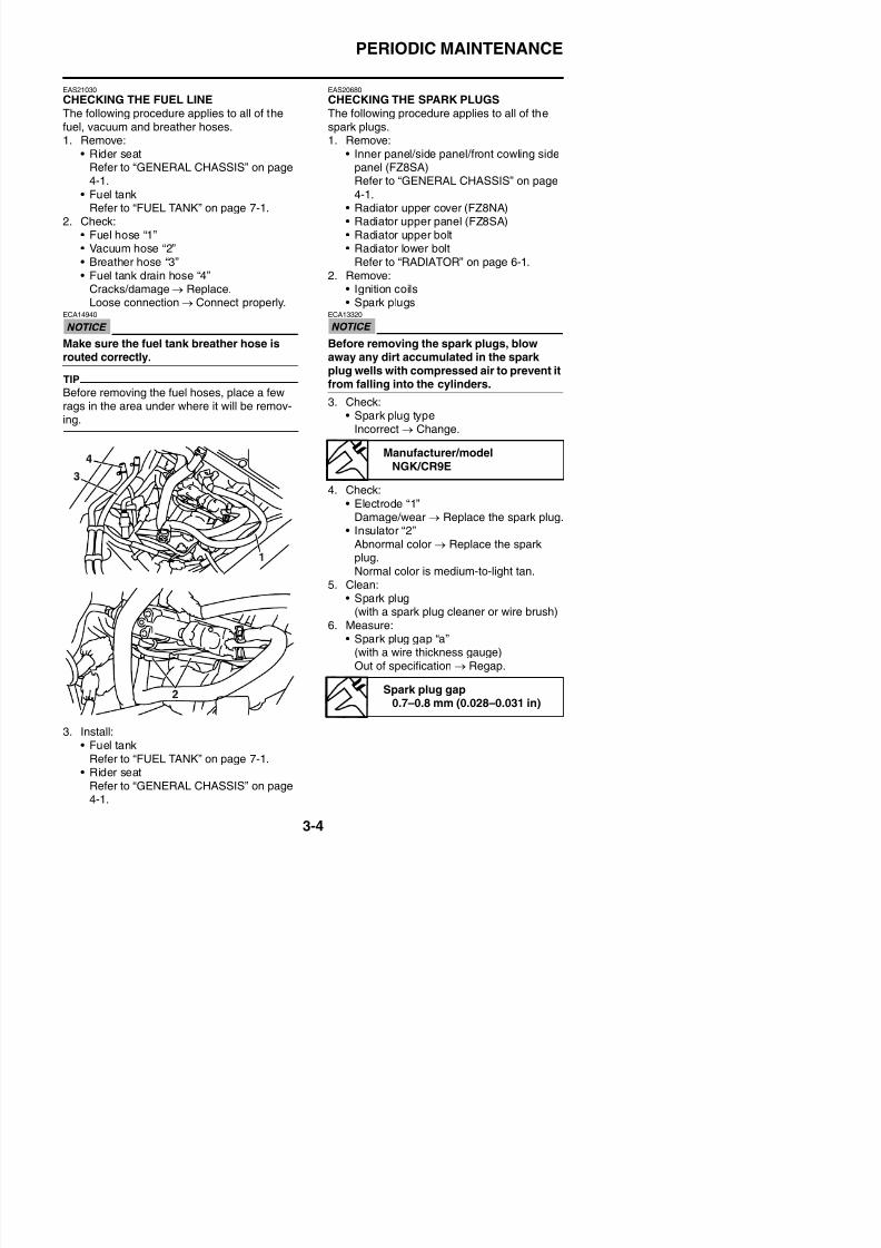
8/21/2019 Fz8 - Service Manual
http://slidepdf.com/reader/full/fz8-service-manual 133/609
Refer to “FUEL TANK” on page 7-1.2. Check:
• Fuel hose “1”
• Vacuum hose “2”• Breather hose “3”• Fuel tank drain hose “4”
Cracks/damage → Replace.Loose connection → Connect properly.
ECA14940
Make sure the fuel tank breather hose is
routed correctly.TIP
Before removing the fuel hoses, place a fewrags in the area under where it will be remov-ing.
• Radiator upper cover (FZ8NA)• Radiator upper panel (FZ8SA)• Radiator upper bolt
• Radiator lower boltRefer to “RADIATOR” on page 6-1.2. Remove:
• Ignition coils• Spark plugs
ECA13320
Before removing the spark plugs, blow
away any dirt accumulated in the sparkplug wells with compressed air to prevent itfrom falling into the cylinders.
3. Check:• Spark plug type
Incorrect → Change.
4. Check:
• Electrode “1”Damage/wear → Replace the spark plug.
• Insulator “2”Abnormal color → Replace the sparkplug.Normal color is medium-to-light tan.
5. Clean:• Spark plug
(with a spark plug cleaner or wire brush)
Manufacturer/model
NGK/CR9E
PERIODIC MAINTENANCE
7 Install:
• Air filter caseRefer to “GENERAL CHASSIS” on page4-1.
• Throttle body assembly
Refer to “THROTTLE BODIES” on page7-5.
• Air cut-off valveRefer to “AIR INDUCTION SYSTEM” onpage 7-15.
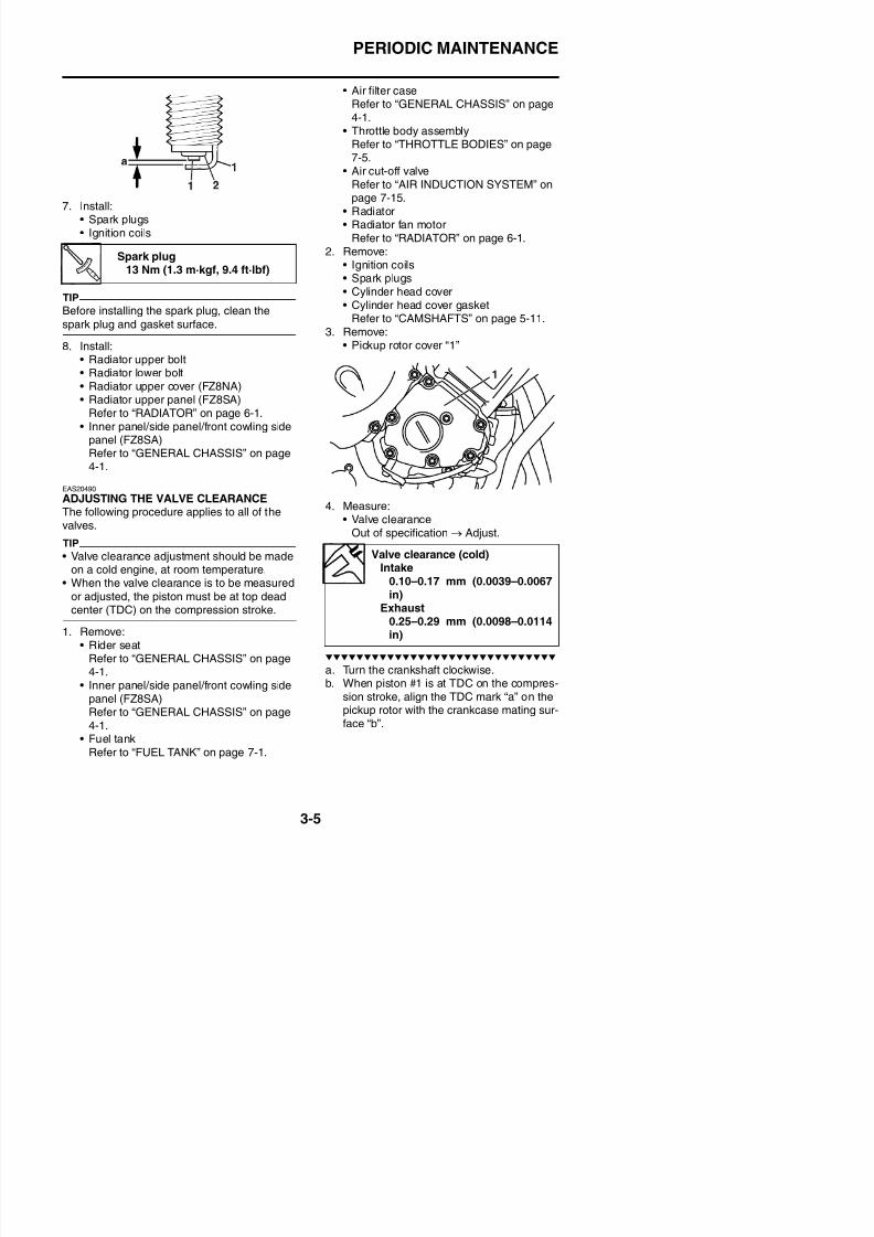
8/21/2019 Fz8 - Service Manual
http://slidepdf.com/reader/full/fz8-service-manual 134/609
7. Install:• Spark plugs• Ignition coils
TIP
Before installing the spark plug, clean the
spark plug and gasket surface.
8. Install:
• Radiator upper bolt• Radiator lower bolt• Radiator upper cover (FZ8NA)• Radiator upper panel (FZ8SA)
Refer to “RADIATOR” on page 6-1.• Inner panel/side panel/front cowling side
panel (FZ8SA)Refer to “GENERAL CHASSIS” on page
4-1.
EAS20490
ADJUSTING THE VALVE CLEARANCEThe following procedure applies to all of thevalves.
TIP
• Valve clearance adjustment should be made
on a cold engine, at room temperature.• When the valve clearance is to be measured
or adjusted, the piston must be at top deadcenter (TDC) on the compression stroke.
• Radiator• Radiator fan motor
Refer to “RADIATOR” on page 6-1.
2. Remove:• Ignition coils• Spark plugs• Cylinder head cover• Cylinder head cover gasket
Refer to “CAMSHAFTS” on page 5-11.3. Remove:
• Pickup rotor cover “1”
4. Measure:• Valve clearance
Out of specification → Adjust.
Spark plug13 Nm (1.3 m·kgf, 9.4 ft·lbf)
Valve clearance (cold)Intake
0.10–0.17 mm (0.0039–0.0067in)
Exhaust
PERIODIC MAINTENANCE
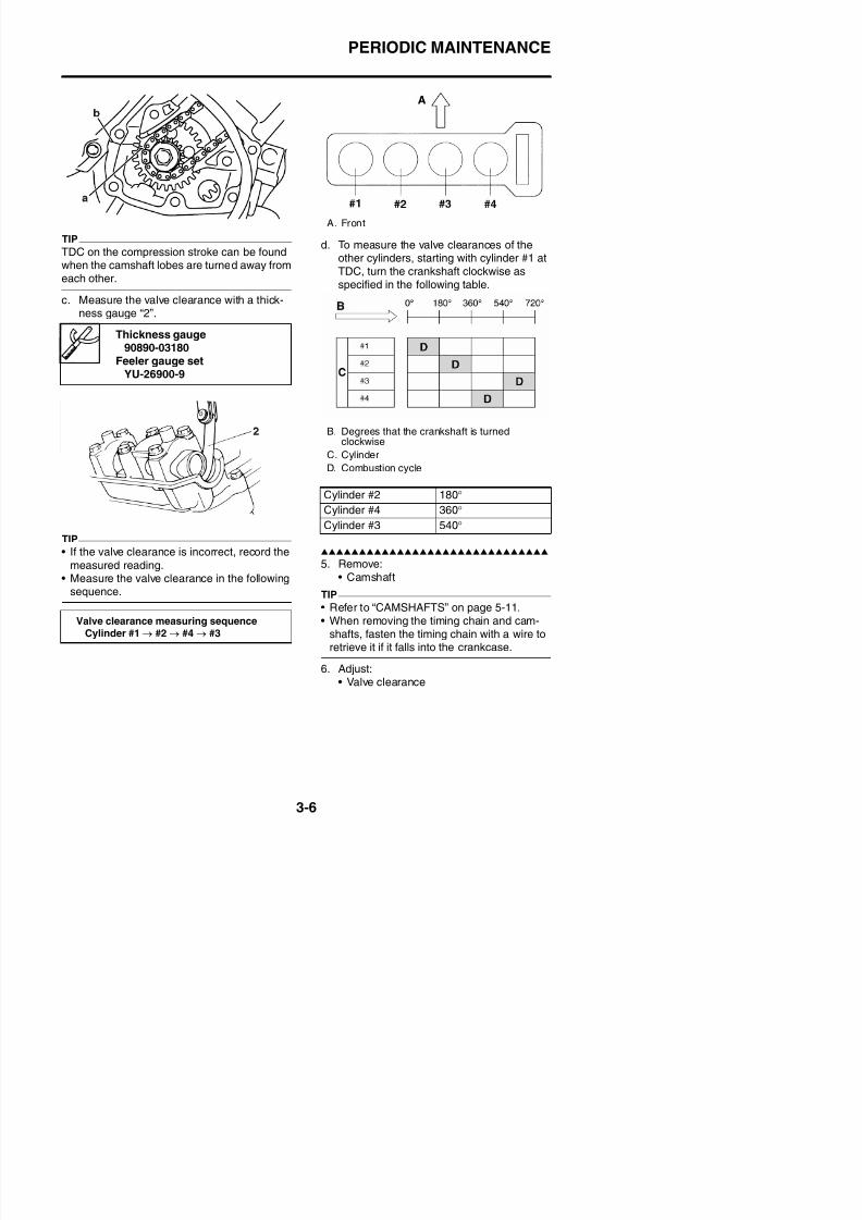
8/21/2019 Fz8 - Service Manual
http://slidepdf.com/reader/full/fz8-service-manual 135/609
TIP
TDC on the compression stroke can be foundwhen the camshaft lobes are turned away fromeach other.
c. Measure the valve clearance with a thick-ness gauge “2”.
TIP
• If the valve clearance is incorrect, record the
measured reading.• Measure the valve clearance in the following
sequence.
d. To measure the valve clearances of theother cylinders, starting with cylinder #1 atTDC, turn the crankshaft clockwise asspecified in the following table.
5. Remove:• Camshaft
TIP
R f t “CAMSHAFTS” 5 11
Thickness gauge90890-03180
Feeler gauge setYU-26900-9
A. Front
B. Degrees that the crankshaft is turnedclockwise
C. CylinderD. Combustion cycle
Cylinder #2 180°
Cylinder #4 360°
Cylinder #3 540°
PERIODIC MAINTENANCE
a. Remove the valve lifter “1” and the valvepad “2” with a valve lapper “3”.
Example:If the valve pad is marked “158”, the padthickness is 1.58 mm (0.062 in).
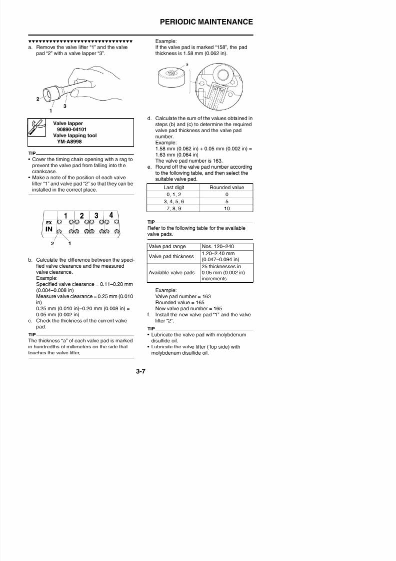
8/21/2019 Fz8 - Service Manual
http://slidepdf.com/reader/full/fz8-service-manual 136/609
TIP
• Cover the timing chain opening with a rag toprevent the valve pad from falling into thecrankcase.
• Make a note of the position of each valve
lifter “1” and valve pad “2” so that they can beinstalled in the correct place.
b. Calculate the difference between the speci-fied valve clearance and the measuredvalve clearance.Example:
d. Calculate the sum of the values obtained insteps (b) and (c) to determine the requiredvalve pad thickness and the valve pad
number.Example:1.58 mm (0.062 in) + 0.05 mm (0.002 in) =1.63 mm (0.064 in)
The valve pad number is 163.e. Round off the valve pad number accordingto the following table, and then select thesuitable valve pad.
TIP
Refer to the following table for the availablevalve pads.
Valve lapper90890-04101
Valve lapping toolYM-A8998
Last digit Rounded value
0, 1, 2 0
3, 4, 5, 6 5
7, 8, 9 10
Valve pad range Nos. 120–240
Valve pad thickness1.20–2.40 mm
(0.047–0.094 in)
Available valve pads25 thicknesses in0.05 mm (0.002 in)increments
PERIODIC MAINTENANCE
• Lubricate the valve lifter (Outer side) withengine oil.
• Install the valve lifter and the valve pad in thecorrect place.
• The valve lifter must turn smoothly whenrotated by hand.
be clean, and the engine should have ade-quate compression.
1. Start the engine and let it warm up for sev-
eral minutes.2. Install:• Digital tachometer
(Use goods on the market)3. Check:
• Engine idling speed
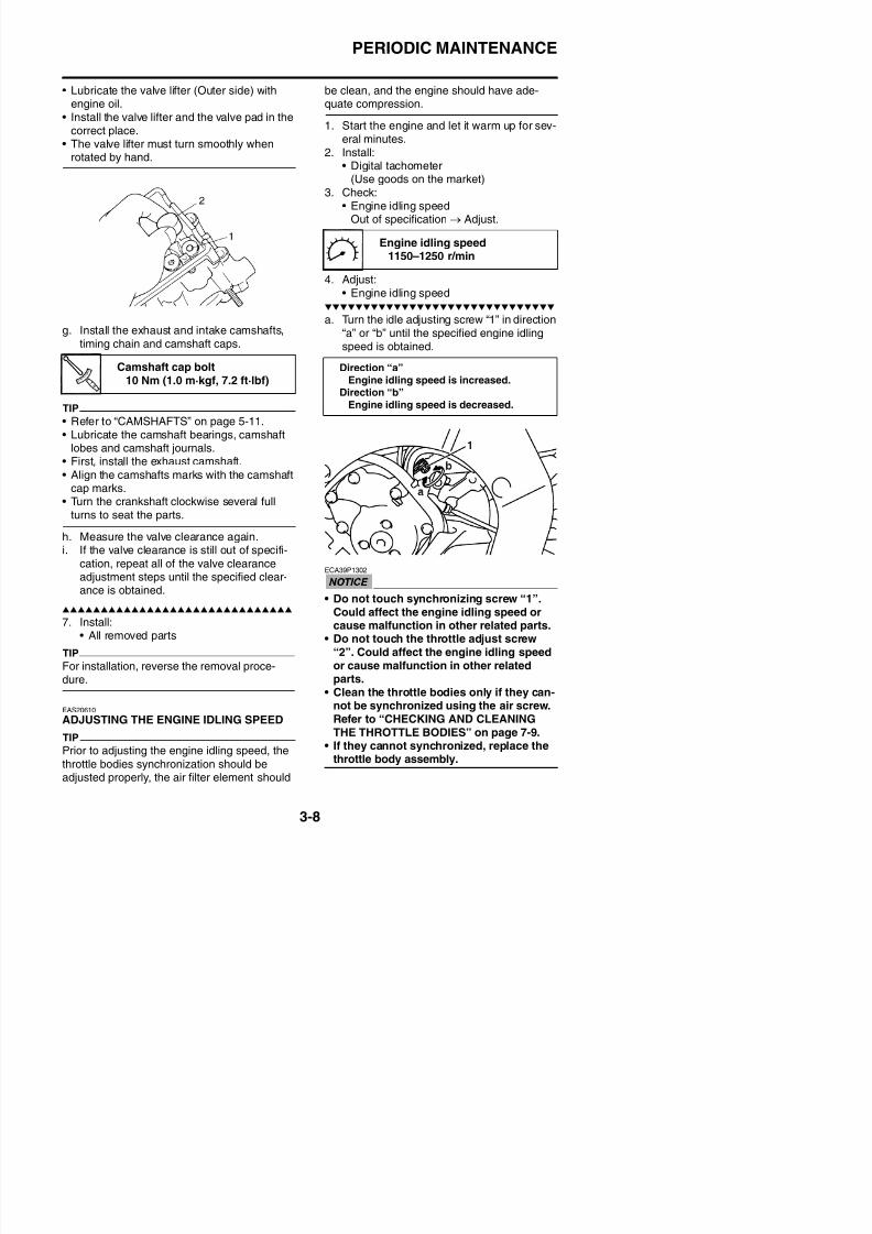
8/21/2019 Fz8 - Service Manual
http://slidepdf.com/reader/full/fz8-service-manual 137/609
g. Install the exhaust and intake camshafts,timing chain and camshaft caps.
TIP
• Refer to “CAMSHAFTS” on page 5-11.• Lubricate the camshaft bearings, camshaft
lobes and camshaft journals.
• First, install the exhaust camshaft.• Align the camshafts marks with the camshaftcap marks.
• Turn the crankshaft clockwise several fullturns to seat the parts.
h. Measure the valve clearance again.i. If the valve clearance is still out of specifi-
cation, repeat all of the valve clearance
adjustment steps until the specified clear-ance is obtained.
Engine idling speedOut of specification → Adjust.
4. Adjust:• Engine idling speed
a. Turn the idle adjusting screw “1” in direction“a” or “b” until the specified engine idlingspeed is obtained.
ECA39P1302
• Do not touch synchronizing screw “1”.Could affect the engine idling speed or
Camshaft cap bolt10 Nm (1.0 m·kgf, 7.2 ft·lbf)
Engine idling speed1150–1250 r/min
Direction “a”Engine idling speed is increased.
Direction “b”Engine idling speed is decreased.
PERIODIC MAINTENANCE
• Fuel tankRefer to “FUEL TANK” on page 7-1.
• Air filter caseRefer to “GENERAL CHASSIS” on page
4-1.3. Remove:
• Synchronizing hoses “1”
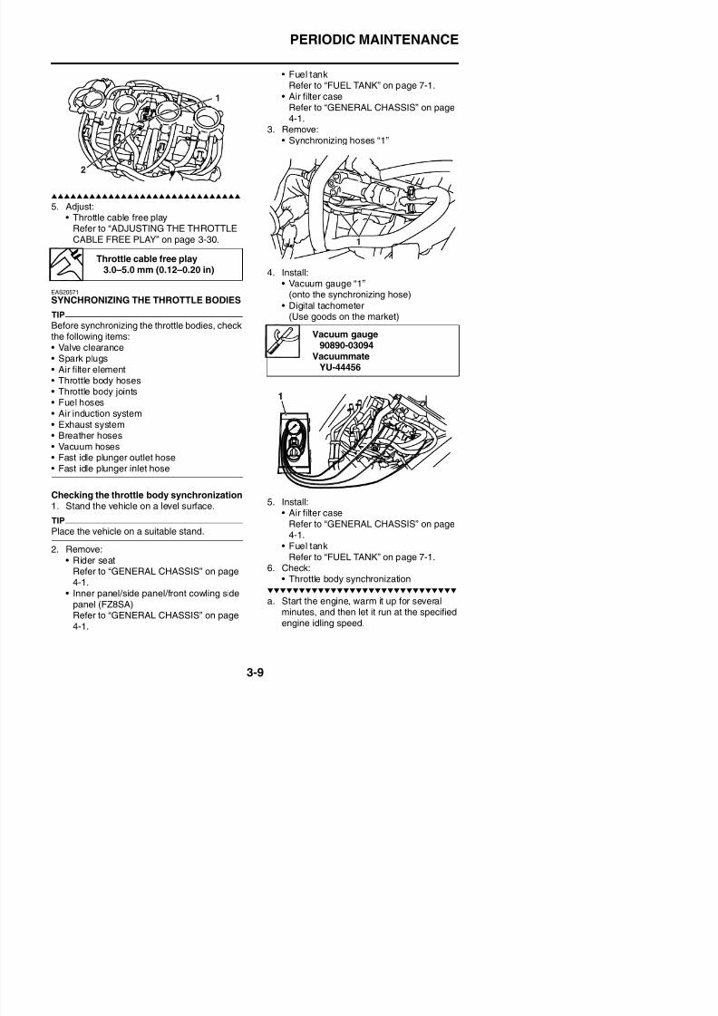
8/21/2019 Fz8 - Service Manual
http://slidepdf.com/reader/full/fz8-service-manual 138/609
5. Adjust:• Throttle cable free play
Refer to “ADJUSTING THE THROTTLECABLE FREE PLAY” on page 3-30.
EAS20571
SYNCHRONIZING THE THROTTLE BODIES
TIP
Before synchronizing the throttle bodies, checkthe following items:• Valve clearance• Spark plugs• Air filter element
• Throttle body hoses• Throttle body joints• Fuel hoses• Air induction system• Exhaust system• Breather hoses• Vacuum hoses• Fast idle plunger outlet hose
• Fast idle plunger inlet hose
Checking the throttle body synchronization1 St d th hi l l l f
4. Install:• Vacuum gauge “1”
(onto the synchronizing hose)• Digital tachometer
(Use goods on the market)
5 Install:
Throttle cable free play3.0–5.0 mm (0.12–0.20 in)
Vacuum gauge90890-03094
VacuummateYU-44456
PERIODIC MAINTENANCE
b. Check the vacuum pressure.
• If a bypass air screw was removed, turn inthe screw fully and be sure to synchronizethe throttle bodies.
• If the throttle body synchronization can not
adjusted by the bypass air screw, clean orreplace the throttle bodies.
• The difference in vacuum pressure betweenthe throttle bodies should not exceed 1.33kPa (10 mmHg).
Engine idling speed1150–1250 r/min
The difference in vacuum pres-sure between the throttle bod-ies should not exceed 1.33 kPa(10 mmHg).
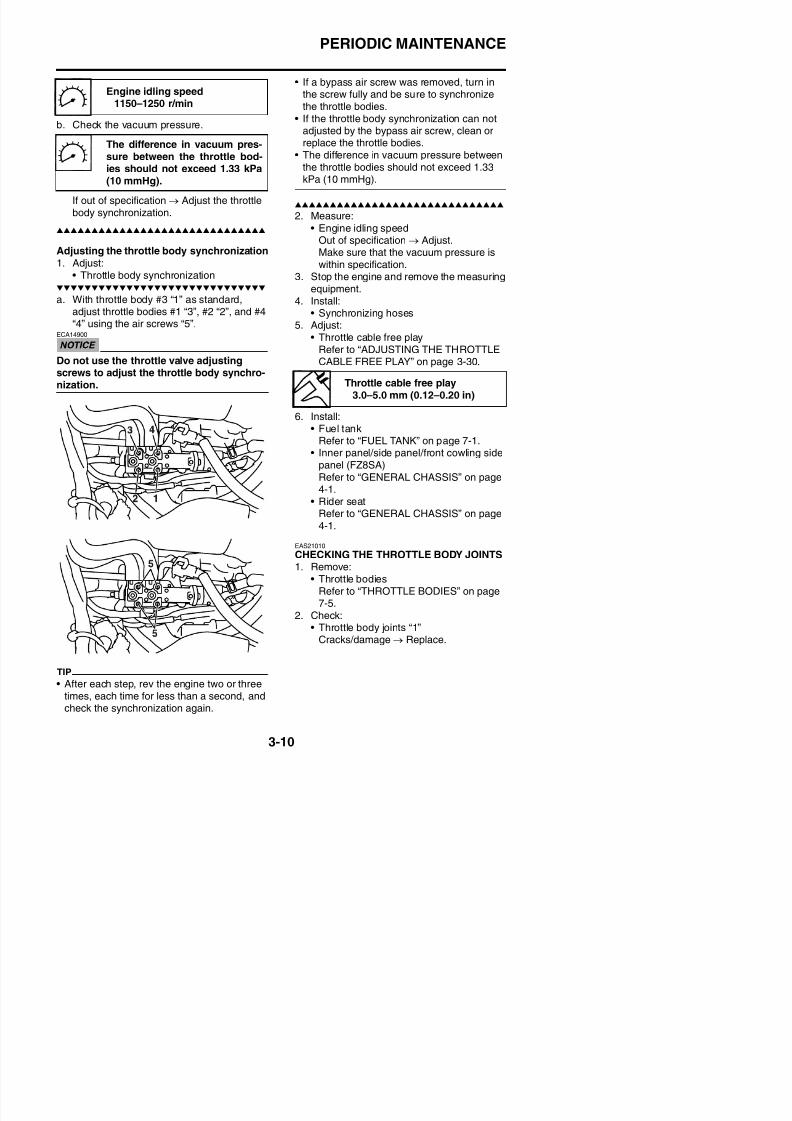
8/21/2019 Fz8 - Service Manual
http://slidepdf.com/reader/full/fz8-service-manual 139/609
If out of specification → Adjust the throttlebody synchronization.
Adjusting the throttle body synchronization1. Adjust:
• Throttle body synchronization
a. With throttle body #3 “1” as standard,adjust throttle bodies #1 “3”, #2 “2”, and #4
“4” using the air screws “5”.ECA14900
Do not use the throttle valve adjustingscrews to adjust the throttle body synchro-nization.
2. Measure:
• Engine idling speedOut of specification → Adjust.Make sure that the vacuum pressure iswithin specification.
3. Stop the engine and remove the measuringequipment.
4. Install:• Synchronizing hoses
5. Adjust:• Throttle cable free play
Refer to “ADJUSTING THE THROTTLECABLE FREE PLAY” on page 3-30.
6. Install:• Fuel tank
Refer to “FUEL TANK” on page 7-1.• Inner panel/side panel/front cowling side
panel (FZ8SA)Refer to “GENERAL CHASSIS” on page4-1.
• Rider seatRefer to “GENERAL CHASSIS” on page4-1.
EAS21010
CHECKING THE THROTTLE BODY JOINTS
Throttle cable free play3.0–5.0 mm (0.12–0.20 in)
PERIODIC MAINTENANCE
3. Install:
4. After selecting “CO”, simultaneously pressthe “SELECT” and “RESET” buttons for 2seconds or more to execute the selection.
5. Press the “SELECT” and “RESET” buttons
to select a cylinder.TIP
The selected cylinder number appears on theclock LCD.• To decrease the selected cylinder number,
press the “RESET” button
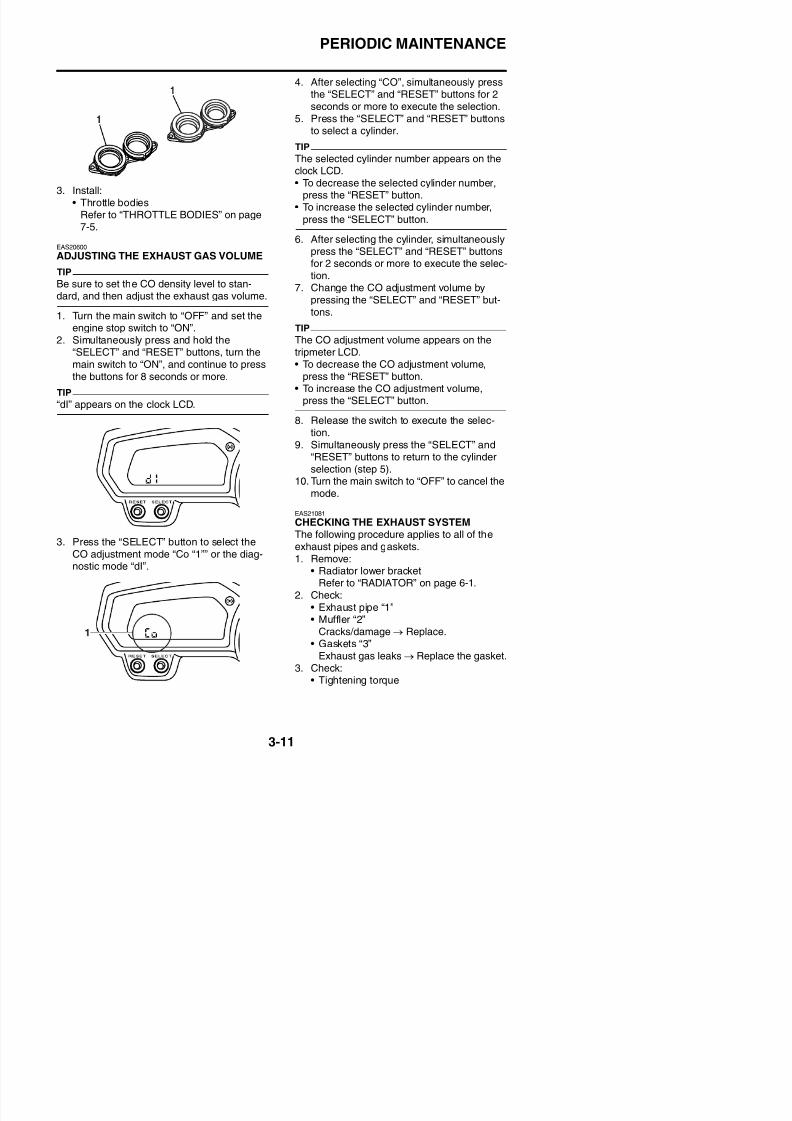
8/21/2019 Fz8 - Service Manual
http://slidepdf.com/reader/full/fz8-service-manual 140/609
3. Install:• Throttle bodies
Refer to “THROTTLE BODIES” on page
7-5.
EAS20600
ADJUSTING THE EXHAUST GAS VOLUME
TIP
Be sure to set the CO density level to stan-dard, and then adjust the exhaust gas volume.
1. Turn the main switch to “OFF” and set the
engine stop switch to “ON”.2. Simultaneously press and hold the
“SELECT” and “RESET” buttons, turn themain switch to “ON”, and continue to pressthe buttons for 8 seconds or more.
TIP
“dI” appears on the clock LCD.
3. Press the “SELECT” button to select theCO adjustment mode “Co “1”” or the diag-
press the RESET button.• To increase the selected cylinder number,
press the “SELECT” button.
6. After selecting the cylinder, simultaneouslypress the “SELECT” and “RESET” buttonsfor 2 seconds or more to execute the selec-tion.
7. Change the CO adjustment volume bypressing the “SELECT” and “RESET” but-tons.
TIPThe CO adjustment volume appears on thetripmeter LCD.• To decrease the CO adjustment volume,
press the “RESET” button.• To increase the CO adjustment volume,
press the “SELECT” button.
8. Release the switch to execute the selec-tion.9. Simultaneously press the “SELECT” and
“RESET” buttons to return to the cylinderselection (step 5).
10. Turn the main switch to “OFF” to cancel themode.
EAS21081
CHECKING THE EXHAUST SYSTEMThe following procedure applies to all of theexhaust pipes and gaskets.1 R
PERIODIC MAINTENANCE
Exhaust pipe nut20 Nm (2.0 m·kgf, 14 ft·lbf)
Exhaust pipe and muffler bolt
20 Nm (2.0 m·kgf, 14 ft·lbf)Exhaust pipe and exhaust pipebracket bolt
20 Nm (2.0 m·kgf, 14 ft·lbf)
Muffler and rear footrest bolt48 Nm (4.8 m·kgf, 35 ft·lbf)
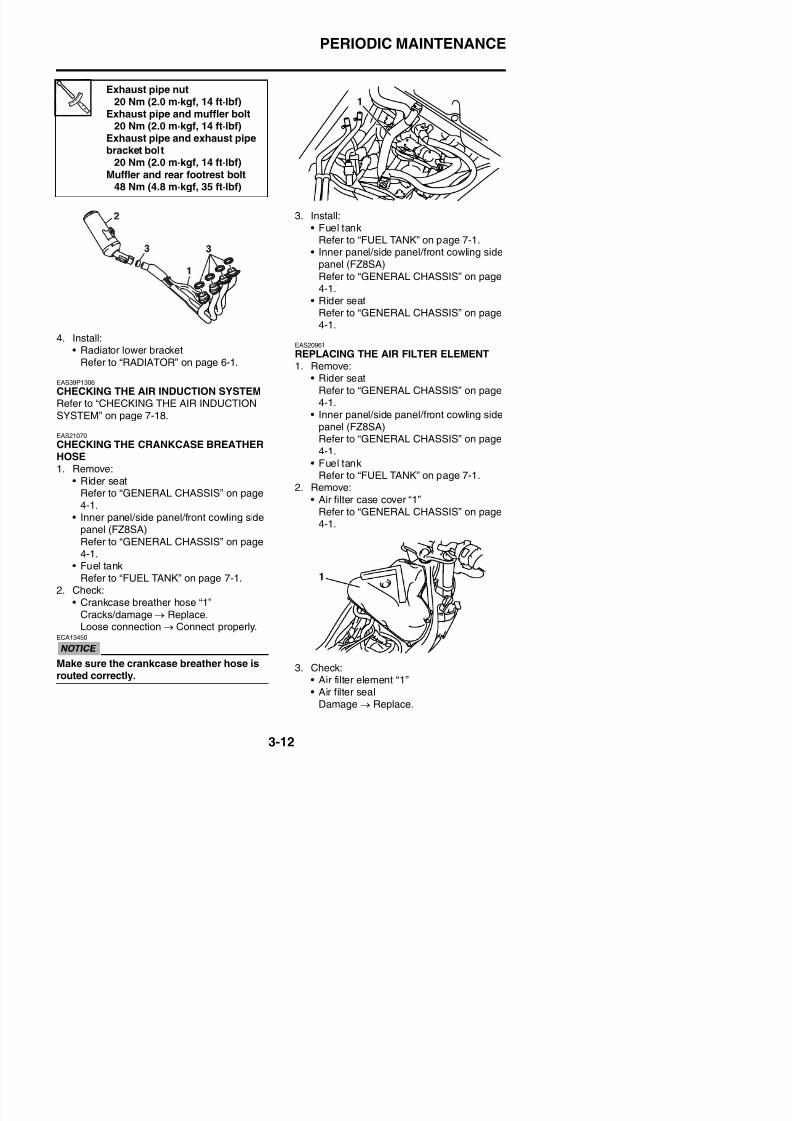
8/21/2019 Fz8 - Service Manual
http://slidepdf.com/reader/full/fz8-service-manual 141/609
4. Install:• Radiator lower bracket
Refer to “RADIATOR” on page 6-1.
EAS39P1306
CHECKING THE AIR INDUCTION SYSTEMRefer to “CHECKING THE AIR INDUCTIONSYSTEM” on page 7-18.
EAS21070
CHECKING THE CRANKCASE BREATHERHOSE1. Remove:
• Rider seatRefer to “GENERAL CHASSIS” on page4-1.
• Inner panel/side panel/front cowling sidepanel (FZ8SA)
Refer to “GENERAL CHASSIS” on page4-1
3. Install:
• Fuel tankRefer to “FUEL TANK” on page 7-1.
• Inner panel/side panel/front cowling sidepanel (FZ8SA)Refer to “GENERAL CHASSIS” on page4-1.
• Rider seatRefer to “GENERAL CHASSIS” on page
4-1.
EAS20961
REPLACING THE AIR FILTER ELEMENT1. Remove:
• Rider seat
Refer to “GENERAL CHASSIS” on page4-1.
• Inner panel/side panel/front cowling side
panel (FZ8SA)Refer to “GENERAL CHASSIS” on page4-1.
• Fuel tankRefer to “FUEL TANK” on page 7-1.
2. Remove:• Air filter case cover “1”
Refer to “GENERAL CHASSIS” on page
4-1.
PERIODIC MAINTENANCE
TIP
• Replace the air filter element every 40000km (24000 mi) of operation.
• The air filter needs more frequent service if
you are riding in unusually wet or dustyareas.
Clutch cable free play10.0–15.0 mm (0.39–0.59 in)
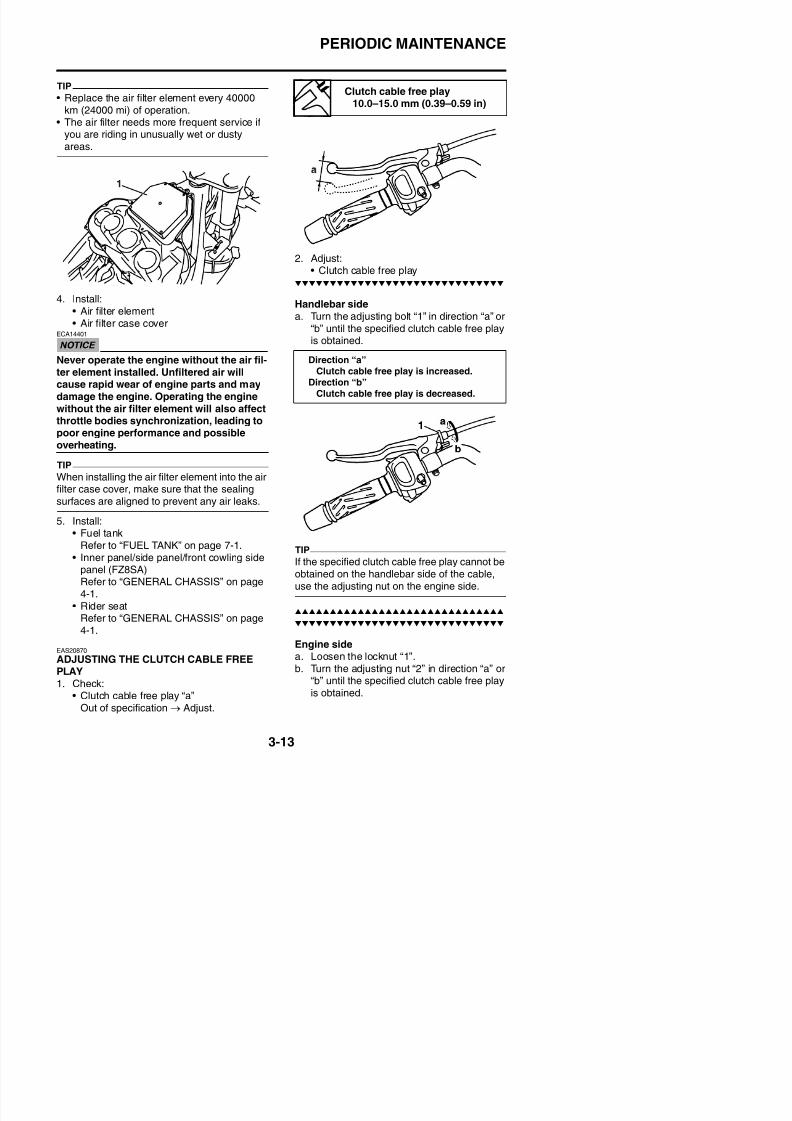
8/21/2019 Fz8 - Service Manual
http://slidepdf.com/reader/full/fz8-service-manual 142/609
4. Install:• Air filter element
• Air filter case coverECA14401
Never operate the engine without the air fil-ter element installed. Unfiltered air willcause rapid wear of engine parts and maydamage the engine. Operating the enginewithout the air filter element will also affect
throttle bodies synchronization, leading topoor engine performance and possibleoverheating.
TIP
When installing the air filter element into the airfilter case cover, make sure that the sealingsurfaces are aligned to prevent any air leaks.
5. Install:• Fuel tank
Refer to “FUEL TANK” on page 7-1.I l/ id l/f t li id
2. Adjust:• Clutch cable free play
Handlebar sidea. Turn the adjusting bolt “1” in direction “a” or
“b” until the specified clutch cable free playis obtained.
TIP
Direction “a”Clutch cable free play is increased.
Direction “b”Clutch cable free play is decreased.
PERIODIC MAINTENANCE
c. Tighten the locknut “1”.
Direction “a”Clutch cable free play is increased.
Direction “b”Clutch cable free play is decreased.
Locknut7 Nm (0.7 m·kgf, 5.1 ft·lbf)
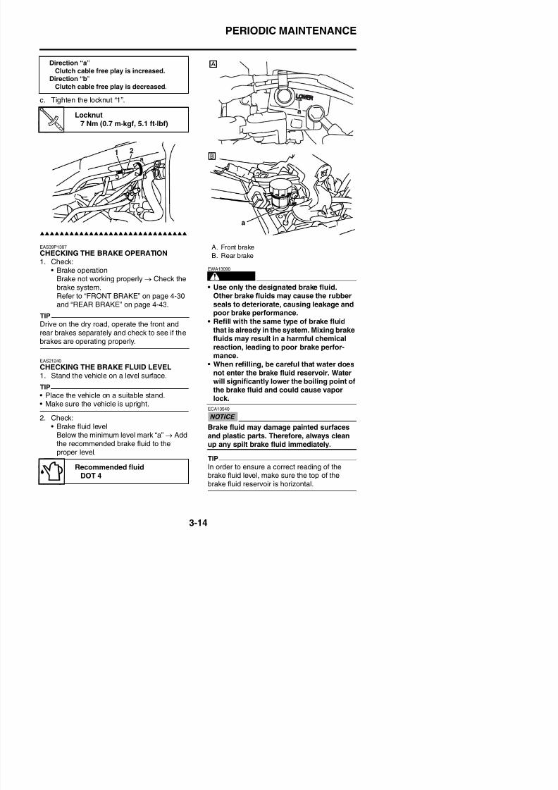
8/21/2019 Fz8 - Service Manual
http://slidepdf.com/reader/full/fz8-service-manual 143/609
EAS39P1307
CHECKING THE BRAKE OPERATION1. Check:
• Brake operationBrake not working properly → Check thebrake system.
Refer to “FRONT BRAKE” on page 4-30 and “REAR BRAKE” on page 4-43.
TIP
Drive on the dry road, operate the front andrear brakes separately and check to see if thebrakes are operating properly.
EAS21240
CHECKING THE BRAKE FLUID LEVEL1. Stand the vehicle on a level surface.
TIP
WARNING
EWA13090
• Use only the designated brake fluid.
Other brake fluids may cause the rubberseals to deteriorate, causing leakage andpoor brake performance.
• Refill with the same type of brake fluidthat is already in the system. Mixing brakefluids may result in a harmful chemicalreaction, leading to poor brake perfor-mance.
• When refilling, be careful that water doesnot enter the brake fluid reservoir. Waterwill significantly lower the boiling point ofthe brake fluid and could cause vapor
A. Front brake
B. Rear brake
PERIODIC MAINTENANCE
EAS21160
ADJUSTING THE FRONT DISC BRAKE1. Adjust:
• Brake lever position(distance “a” from the throttle grip to thebrake lever)
TIP
• While pushing the brake lever forward, turnthe adjusting dial “1” until the brake lever is inthe desired position.B t li th tti th dj ti
EAS21250
CHECKING THE FRONT BRAKE PADSThe following procedure applies to all of thebrake pads.1. Operate the brake.2. Check:
• Front brake padWear indicators “1” almost touch the
brake disc → Replace the brake pads asa set.Refer to “FRONT BRAKE” on page 4-30
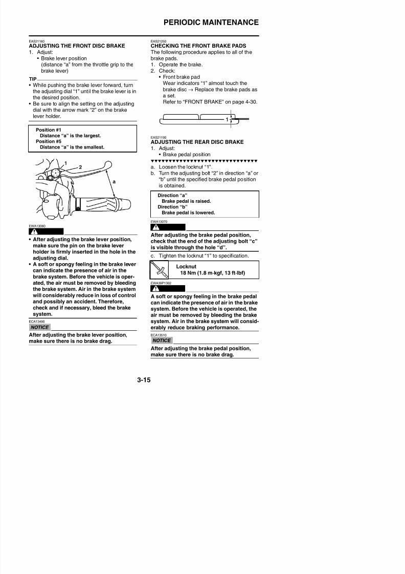
8/21/2019 Fz8 - Service Manual
http://slidepdf.com/reader/full/fz8-service-manual 144/609
• Be sure to align the setting on the adjustingdial with the arrow mark “2” on the brake
lever holder.
WARNING
EWA13060
• After adjusting the brake lever position,make sure the pin on the brake leverholder is firmly inserted in the hole in theadjusting dial.
• A soft or spongy feeling in the brake levercan indicate the presence of air in the
brake system. Before the vehicle is oper-ated, the air must be removed by bleeding
Refer to FRONT BRAKE on page 4-30.
EAS21190
ADJUSTING THE REAR DISC BRAKE1. Adjust:
• Brake pedal position
a. Loosen the locknut “1”.b. Turn the adjusting bolt “2” in direction “a” or
“b” until the specified brake pedal positionis obtained.
WARNING
EWA13070
After adjusting the brake pedal position,check that the end of the adjusting bolt “c”is visible through the hole “d”.
c. Tighten the locknut “1” to specification.
EWA39P1302
Position #1Distance “a” is the largest.
Position #5Distance “a” is the smallest.
Direction “a”Brake pedal is raised.
Direction “b”Brake pedal is lowered.
Locknut18 Nm (1.8 m·kgf, 13 ft·lbf)
PERIODIC MAINTENANCE
TIP
• Be careful not to spill any brake fluid or allowthe brake master cylinder reservoir or brakefluid reservoir to overflow.
• When bleeding the hydraulic brake system,make sure there is always enough brake fluidbefore applying the brake. Ignoring this pre-caution could allow air to enter the hydraulicbrake system, considerably lengthening thebleeding procedure.
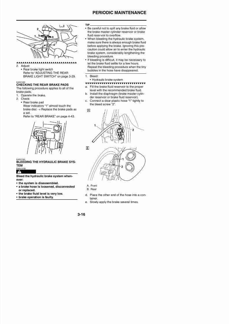
8/21/2019 Fz8 - Service Manual
http://slidepdf.com/reader/full/fz8-service-manual 145/609
2. Adjust:• Rear brake light switch
Refer to “ADJUSTING THE REARBRAKE LIGHT SWITCH” on page 3-29.
EAS21260
CHECKING THE REAR BRAKE PADSThe following procedure applies to all of thebrake pads.
1. Operate the brake.2. Check:
• Rear brake padWear indicators “1” almost touch thebrake disc → Replace the brake pads as
a set.Refer to “REAR BRAKE” on page 4-43.
EAS21350
• If bleeding is difficult, it may be necessary to
let the brake fluid settle for a few hours.
Repeat the bleeding procedure when the tinybubbles in the hose have disappeared.
1. Bleed:• Hydraulic brake system
a. Fill the brake fluid reservoir to the properlevel with the recommended brake fluid.
b. Install the diaphragm (brake master cylin-der reservoir or brake fluid reservoir).c. Connect a clear plastic hose “1” tightly to
the bleed screw “2”.
PERIODIC MAINTENANCE
f. Fully pull the brake lever or fully pressdown the brake pedal and hold it in posi-tion.
g. Loosen the bleed screw.
TIPLoosening the bleed screw will release thepressure and cause the brake lever to contactthe throttle grip or the brake pedal to fullyextend.
h Tighten the bleed screw and then release
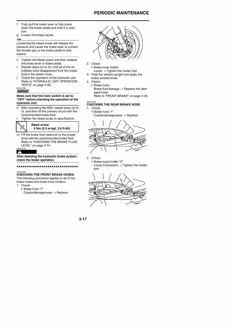
8/21/2019 Fz8 - Service Manual
http://slidepdf.com/reader/full/fz8-service-manual 146/609
h. Tighten the bleed screw and then releasethe brake lever or brake pedal.
i. Repeat steps (e) to (h) until all of the airbubbles have disappeared from the brakefluid in the plastic hose.
j. Check the operation of the hydraulic unit.Refer to “HYDRAULIC UNIT OPERATIONTESTS” on page 4-60.
ECA14780
Make sure that the main switch is set to“OFF” before checking the operation of thehydraulic unit.
k. After operating the ABS, repeat steps (e) to(i), and then fill the primary circuit with therecommended brake fluid.
l. Tighten the bleed screw to specification.
m. Fill the brake fluid reservoir to the properlevel with the recommended brake fluid.Refer to “CHECKING THE BRAKE FLUIDLEVEL” on page 3-14.
WARNING
EWA13110
After bleeding the hydraulic brake system,check the brake operation.
2. Check:
• Brake hose holderLoose → Tighten the holder bolt.
3. Hold the vehicle upright and apply thebrake several times.
4. Check:• Brake hose
Brake fluid leakage → Replace the dam-aged hose.
Refer to “FRONT BRAKE” on page 4-30.EAS21290
CHECKING THE REAR BRAKE HOSE1. Check:
• Brake hose “1”
Cracks/damage/wear → Replace.
2. Check:• Brake hose holder “2”
L C i Ti h h h ld
Bleed screw5 Nm (0.5 m·kgf, 3.6 ft·lbf)
PERIODIC MAINTENANCE
3. Hold the vehicle upright and apply the rearbrake several times.
4. Check:• Brake hose
Brake fluid leakage → Replace the dam-aged hose.Refer to “REAR BRAKE” on page 4-43.
EAS21670
CHECKING THE WHEELSThe following procedure applies to both of the
NEVER OVERLOAD THE VEHICLE.
Tire air pressure (measured oncold tires)
Loading condition0–90 kg (0–198 lb)
Front250 kPa (2.50 kgf/cm², 36 psi)
Rear290 kPa (2.90 kgf/cm², 42 psi)
Loading condition
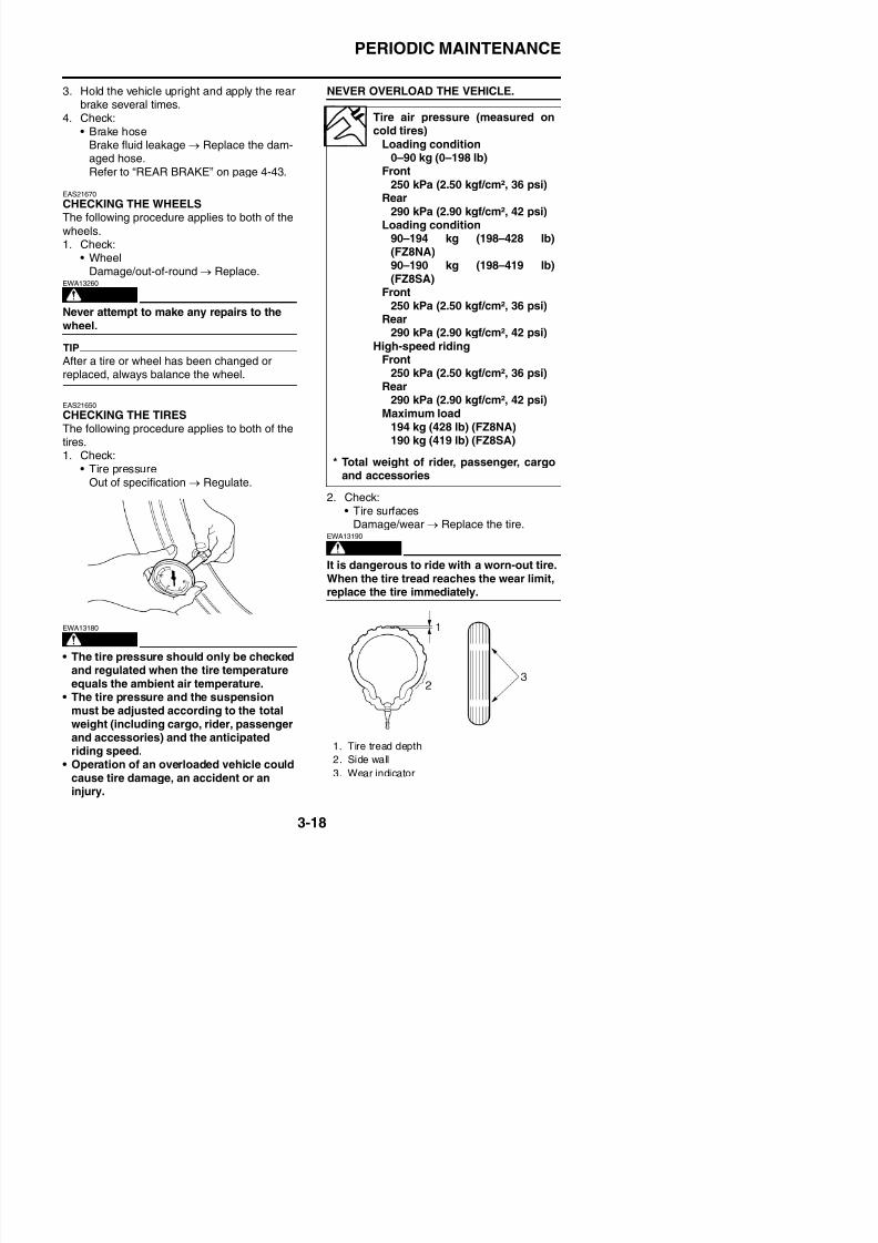
8/21/2019 Fz8 - Service Manual
http://slidepdf.com/reader/full/fz8-service-manual 147/609
wheels.1. Check:
• WheelDamage/out-of-round → Replace.
WARNING
EWA13260
Never attempt to make any repairs to the
wheel.
TIP
After a tire or wheel has been changed orreplaced, always balance the wheel.
EAS21650
CHECKING THE TIRESThe following procedure applies to both of thetires.1. Check:
• Tire pressureOut of specification → Regulate.
2. Check:• Tire surfaces
Damage/wear → Replace the tire.
WARNING
EWA13190
It is dangerous to ride with a worn-out tire.
When the tire tread reaches the wear limit,replace the tire immediately.
Loading condition90–194 kg (198–428 lb)
(FZ8NA)90–190 kg (198–419 lb)(FZ8SA)
Front250 kPa (2.50 kgf/cm², 36 psi)
Rear290 kPa (2.90 kgf/cm², 42 psi)
High-speed riding
Front250 kPa (2.50 kgf/cm², 36 psi)Rear
290 kPa (2.90 kgf/cm², 42 psi)Maximum load
194 kg (428 lb) (FZ8NA)190 kg (419 lb) (FZ8SA)
* Total weight of rider, passenger, cargo
and accessories
PERIODIC MAINTENANCE
WARNING
EWA14090
After extensive tests, the tires listed belowhave been approved by Yamaha Motor Co.,Ltd. for this model. The front and rear tiresshould always be by the same manufac
Wear limit (front)1.6 mm (0.06 in)
Wear limit (rear)1.6 mm (0.06 in)
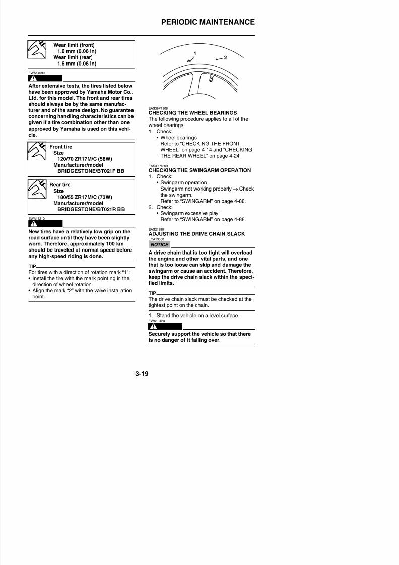
8/21/2019 Fz8 - Service Manual
http://slidepdf.com/reader/full/fz8-service-manual 148/609
should always be by the same manufac-turer and of the same design. No guarantee
concerning handling characteristics can begiven if a tire combination other than oneapproved by Yamaha is used on this vehi-cle.
WARNING
EWA13210
New tires have a relatively low grip on theroad surface until they have been slightlyworn. Therefore, approximately 100 kmshould be traveled at normal speed beforeany high-speed riding is done.
TIP
For tires with a direction of rotation mark “1”:• Install the tire with the mark pointing in the
EAS39P1308
CHECKING THE WHEEL BEARINGSThe following procedure applies to all of thewheel bearings.1. Check:
• Wheel bearingsRefer to “CHECKING THE FRONTWHEEL” on page 4-14 and “CHECKINGTHE REAR WHEEL” on page 4-24.
EAS39P1309
CHECKING THE SWINGARM OPERATION1. Check:
• Swingarm operationSwingarm not working properly → Checkthe swingarm.Refer to “SWINGARM” on page 4-88.
2. Check:
• Swingarm excessive playRefer to “SWINGARM” on page 4-88.
EAS21390
ADJUSTING THE DRIVE CHAIN SLACKECA13550
A drive chain that is too tight will overloadthe engine and other vital parts, and one
that is too loose can skip and damage theswingarm or cause an accident. Therefore,keep the drive chain slack within the speci-
Front tireSize
120/70 ZR17M/C (58W)
Manufacturer/modelBRIDGESTONE/BT021F BB
Rear tireSize
180/55 ZR17M/C (73W)Manufacturer/model
BRIDGESTONE/BT021R BB
PERIODIC MAINTENANCE
TIP
Place the vehicle on a suitable stand so thatthe rear wheel is elevated.
2. Move the rear wheel several times and findthe tightest position of drive chain.3. Check:
• Drive chain slack “a”Out of specification → Adjust.
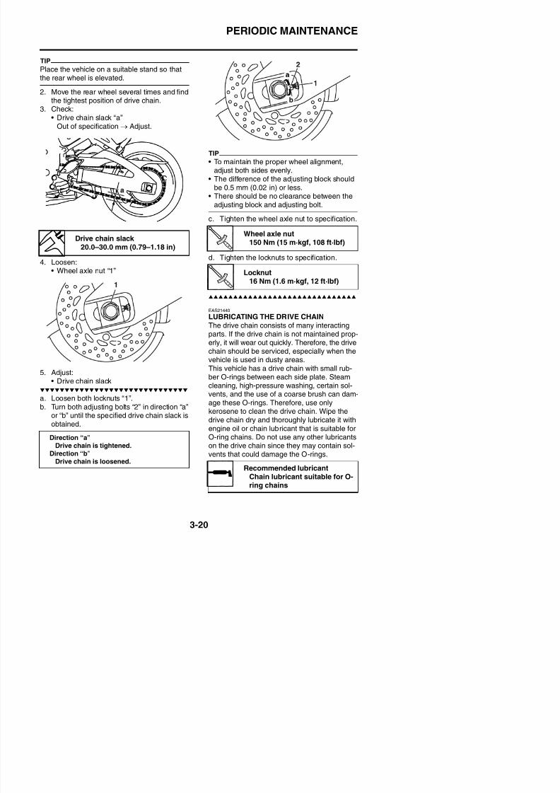
8/21/2019 Fz8 - Service Manual
http://slidepdf.com/reader/full/fz8-service-manual 149/609
4. Loosen:• Wheel axle nut “1”
5. Adjust:• Drive chain slack
TIP
• To maintain the proper wheel alignment,adjust both sides evenly.
• The difference of the adjusting block shouldbe 0.5 mm (0.02 in) or less.
• There should be no clearance between theadjusting block and adjusting bolt.
c. Tighten the wheel axle nut to specification.
d. Tighten the locknuts to specification.
EAS21440
LUBRICATING THE DRIVE CHAINThe drive chain consists of many interactingparts. If the drive chain is not maintained prop-erly, it will wear out quickly. Therefore, the drivechain should be serviced, especially when thevehicle is used in dusty areas.
This vehicle has a drive chain with small rub-ber O-rings between each side plate. Steamcleaning, high-pressure washing, certain sol-vents and the use of a coarse brush can dam
Drive chain slack 20.0–30.0 mm (0.79–1.18 in)
Wheel axle nut150 Nm (15 m·kgf, 108 ft·lbf)
Locknut16 Nm (1.6 m·kgf, 12 ft·lbf)
PERIODIC MAINTENANCE
EAS21510
CHECKING AND ADJUSTING THE STEER-ING HEAD1. Stand the vehicle on a level surface.
WARNING
EWA13120
Securely support the vehicle so that thereis no danger of it falling over.
TIP
Place the vehicle on a suitable stand so that
the front wheel is elevated
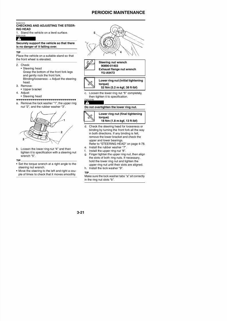
8/21/2019 Fz8 - Service Manual
http://slidepdf.com/reader/full/fz8-service-manual 150/609
the front wheel is elevated.
2. Check:• Steering headGrasp the bottom of the front fork legsand gently rock the front fork.Blinding/looseness → Adjust the steeringhead.
3. Remove:• Upper bracket
4. Adjust:• Steering head
a. Remove the lock washer “1”, the upper ringnut “2”, and the rubber washer “3”.
b. Loosen the lower ring nut “4” and thentighten it to specification with a steering nutwrench “5”.
c. Loosen the lower ring nut “6” completely,then tighten it to specification.
WARNING
EWA13140
Do not overtighten the lower ring nut.
d. Check the steering head for looseness or
binding by turning the front fork all the wayin both directions. If any binding is felt,remove the lower bracket and check theupper and lower bearings.Refer to “STEERING HEAD” on page 4-78.
e. Install the rubber washer “7”.
f. Install the upper ring nut “8”.g. Finger tighten the upper ring nut, then align
the slots of both ring nuts. If necessary,
Steering nut wrench
90890-01403Exhaust flange nut wrench
YU-A9472
Lower ring nut (initial tighteningtorque)
52 Nm (5.2 m·kgf, 38 ft·lbf)
Lower ring nut (final tighteningtorque)
18 Nm (1.8 m·kgf, 13 ft·lbf)
PERIODIC MAINTENANCE
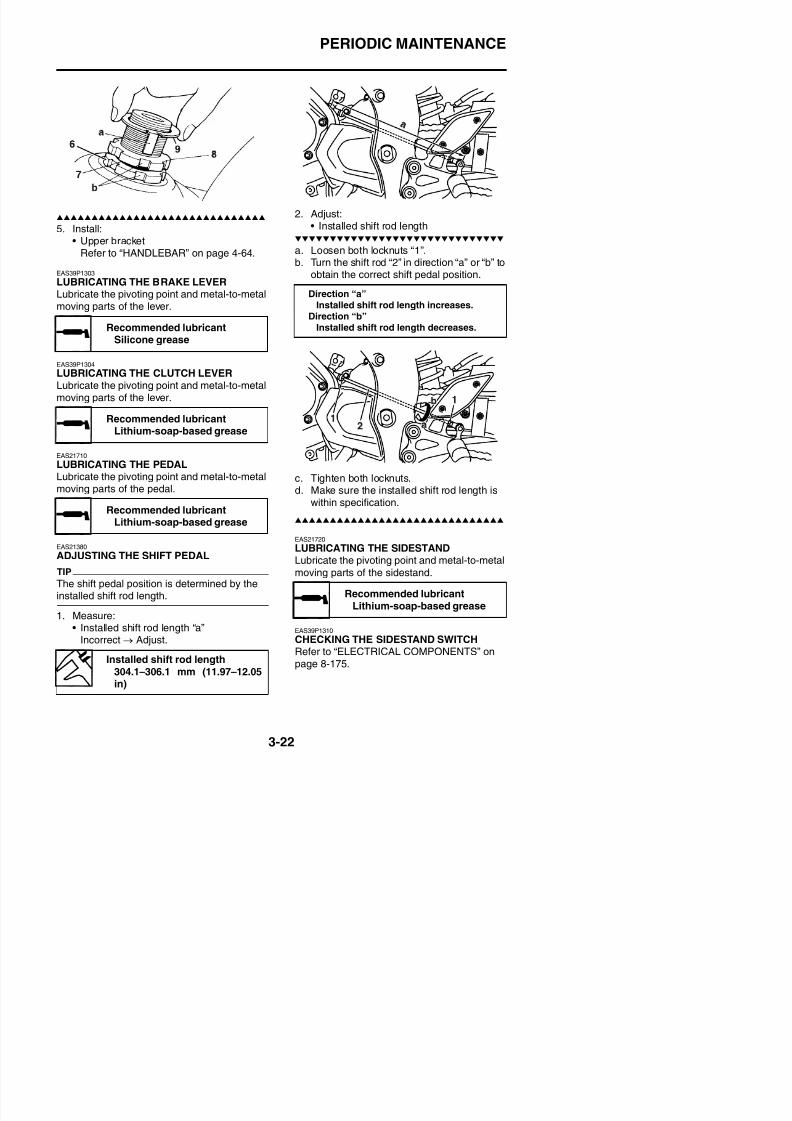
8/21/2019 Fz8 - Service Manual
http://slidepdf.com/reader/full/fz8-service-manual 151/609
5. Install:• Upper bracket
Refer to “HANDLEBAR” on page 4-64.
EAS39P1303
LUBRICATING THE BRAKE LEVERLubricate the pivoting point and metal-to-metalmoving parts of the lever.
EAS39P1304
LUBRICATING THE CLUTCH LEVERLubricate the pivoting point and metal-to-metalmoving parts of the lever.
EAS21710
LUBRICATING THE PEDALLubricate the pivoting point and metal-to-metalmoving parts of the pedal.
EAS21380
ADJUSTING THE SHIFT PEDAL
2. Adjust:• Installed shift rod length
a. Loosen both locknuts “1”.b. Turn the shift rod “2” in direction “a” or “b” to
obtain the correct shift pedal position.
c. Tighten both locknuts.d. Make sure the installed shift rod length is
within specification.
EAS21720
LUBRICATING THE SIDESTAND
Recommended lubricantSilicone grease
Recommended lubricantLithium-soap-based grease
Recommended lubricant
Lithium-soap-based grease
Direction “a”Installed shift rod length increases.
Direction “b”
Installed shift rod length decreases.
PERIODIC MAINTENANCE
EAS21531
CHECKING THE FRONT FORK1. Stand the vehicle on a level surface.
WARNING
EWA13120
Securely support the vehicle so that thereis no danger of it falling over.
2. Check:• Inner tube
Damage/scratches → Replace.• Front fork leg
EAS21590
ADJUSTING THE REAR SHOCKABSORBER ASSEMBLY
WARNING
EWA13120
Securely support the vehicle so that thereis no danger of it falling over.
Spring preloadECA13590
N b d th i i i
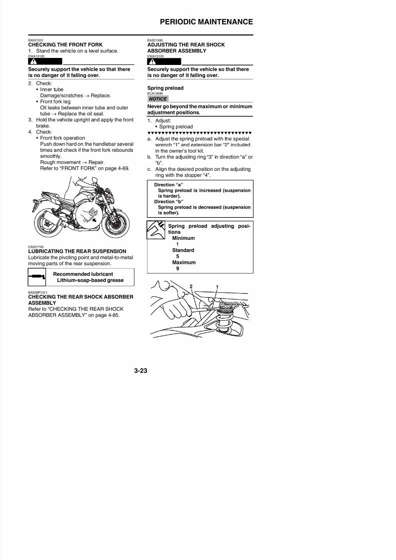
8/21/2019 Fz8 - Service Manual
http://slidepdf.com/reader/full/fz8-service-manual 152/609
Oil leaks between inner tube and outer
tube→
Replace the oil seal.3. Hold the vehicle upright and apply the frontbrake.
4. Check:• Front fork operation
Push down hard on the handlebar severaltimes and check if the front fork reboundssmoothly.
Rough movement→
Repair.Refer to “FRONT FORK” on page 4-69.
EAS21740
LUBRICATING THE REAR SUSPENSIONLubricate the pivoting point and metal-to-metal
moving parts of the rear suspension.
Never go beyond the maximum or minimumadjustment positions.
1. Adjust:• Spring preload
a. Adjust the spring preload with the specialwrench “1” and extension bar “2” includedin the owner’s tool kit.
b. Turn the adjusting ring “3” in direction “a” or
“b”.c. Align the desired position on the adjustingring with the stopper “4”.
Recommended lubricant
Direction “a”Spring preload is increased (suspensionis harder).
Direction “b”Spring preload is decreased (suspension
is softer).
Spring preload adjusting posi-tions
Minimum1
Standard5
Maximum9
PERIODIC MAINTENANCE
Recommended brandYAMALUBE
TypeSAE 10W-30, SAE 10W-40,
SAE 10W-50, SAE 15W-40,SAE 20W-40 or SAE 20W-50
Recommended engine oil grade
API service SG type or higher,JASO standard MA
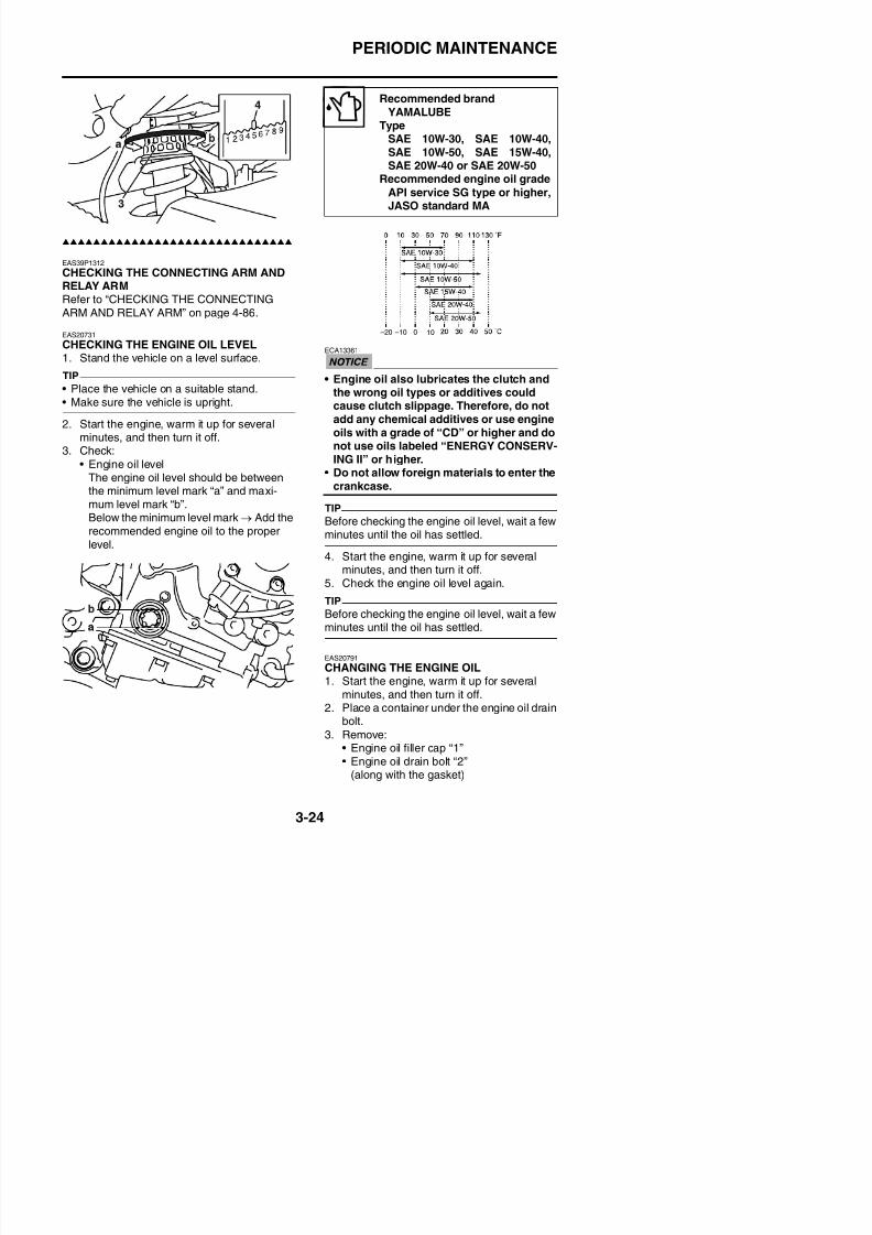
8/21/2019 Fz8 - Service Manual
http://slidepdf.com/reader/full/fz8-service-manual 153/609
EAS39P1312
CHECKING THE CONNECTING ARM ANDRELAY ARMRefer to “CHECKING THE CONNECTINGARM AND RELAY ARM” on page 4-86.
EAS20731
CHECKING THE ENGINE OIL LEVEL
1. Stand the vehicle on a level surface.TIP
• Place the vehicle on a suitable stand.• Make sure the vehicle is upright.
2. Start the engine, warm it up for severalminutes, and then turn it off.
3. Check:
• Engine oil levelThe engine oil level should be betweenthe minimum level mark “a” and maxi-mum level mark “b”.Below the minimum level mark → Add therecommended engine oil to the properlevel.
ECA13361
• Engine oil also lubricates the clutch andthe wrong oil types or additives couldcause clutch slippage. Therefore, do notadd any chemical additives or use engineoils with a grade of “CD” or higher and donot use oils labeled “ENERGY CONSERV-ING II” or higher.
• Do not allow foreign materials to enter thecrankcase.
TIP
Before checking the engine oil level, wait a fewminutes until the oil has settled.
4. Start the engine, warm it up for severalminutes, and then turn it off.
5. Check the engine oil level again.
TIP
Before checking the engine oil level wait a few
–20 –10 0 10
PERIODIC MAINTENANCE
c. Tighten the new oil filter cartridge to speci-fi ti ith il filt h
3
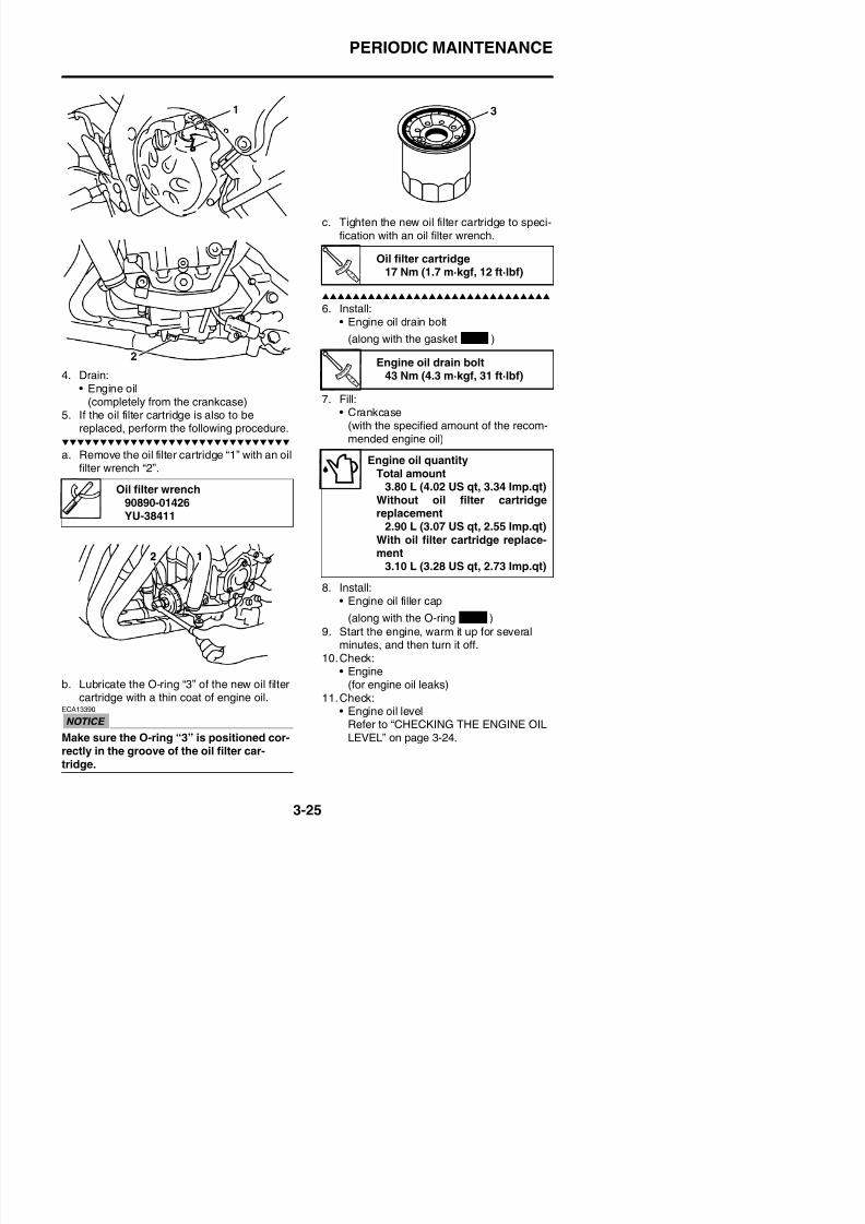
8/21/2019 Fz8 - Service Manual
http://slidepdf.com/reader/full/fz8-service-manual 154/609
4. Drain:• Engine oil
(completely from the crankcase)5. If the oil filter cartridge is also to be
replaced, perform the following procedure.
a. Remove the oil filter cartridge “1” with an oil
filter wrench “2”.
fication with an oil filter wrench.
6. Install:• Engine oil drain bolt
(along with the gasket )
7. Fill:• Crankcase
(with the specified amount of the recom-mended engine oil)
8. Install:• Engine oil filler cap
Oil filter wrench90890-01426YU-38411
Oil filter cartridge17 Nm (1.7 m·kgf, 12 ft·lbf)
Engine oil drain bolt43 Nm (4.3 m·kgf, 31 ft·lbf)
Engine oil quantityTotal amount
3.80 L (4.02 US qt, 3.34 Imp.qt)Without oil filter cartridgereplacement
2.90 L (3.07 US qt, 2.55 Imp.qt)
With oil filter cartridge replace-ment
3.10 L (3.28 US qt, 2.73 Imp.qt)
New
PERIODIC MAINTENANCE
EAS20820
MEASURING THE ENGINE OIL PRESSURE1. Check:
• Engine oil levelBelow the minimum level mark “a” → Add
the recommended engine oil to theproper level.
5 Measure:
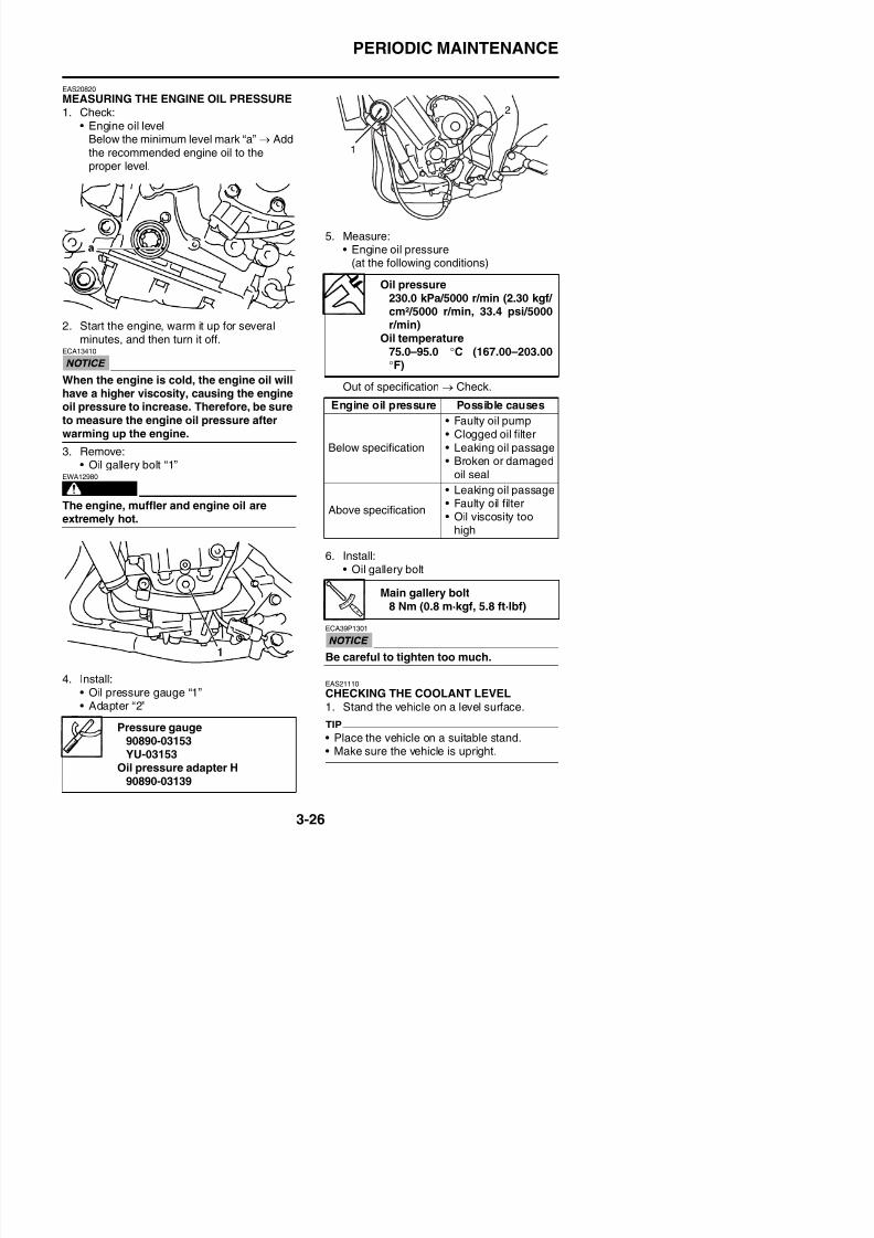
8/21/2019 Fz8 - Service Manual
http://slidepdf.com/reader/full/fz8-service-manual 155/609
2. Start the engine, warm it up for severalminutes, and then turn it off.
ECA13410
When the engine is cold, the engine oil willhave a higher viscosity, causing the engineoil pressure to increase. Therefore, be sureto measure the engine oil pressure afterwarming up the engine.
3. Remove:• Oil gallery bolt “1”
WARNING
EWA12980
The engine, muffler and engine oil areextremely hot.
5. Measure:• Engine oil pressure
(at the following conditions)
Out of specification → Check.
6. Install:• Oil gallery bolt
Oil pressure230.0 kPa/5000 r/min (2.30 kgf/ cm²/5000 r/min, 33.4 psi/5000r/min)
Oil temperature75.0–95.0 °C (167.00–203.00
°F)
Engine oil pressure Possible causes
Below specification
• Faulty oil pump• Clogged oil filter• Leaking oil passage• Broken or damaged
oil seal
Above specification
• Leaking oil passage• Faulty oil filter• Oil viscosity too
high
Main gallery bolt8 Nm (0.8 m·kgf, 5.8 ft·lbf)
PERIODIC MAINTENANCE
2. Check:• Coolant level
The coolant level should be between themaximum level mark “a” and minimum
level mark “b”.Below the minimum level mark → Add therecommended coolant to the proper level.
• Water pump outlet pipe “10”Cracks/damage → Replace.Refer to “RADIATOR” on page 6-1, “OILCOOLER” on page 6-5, “THERMOSTAT”
on page 6-7 and “WATER PUMP” onpage 6-11.
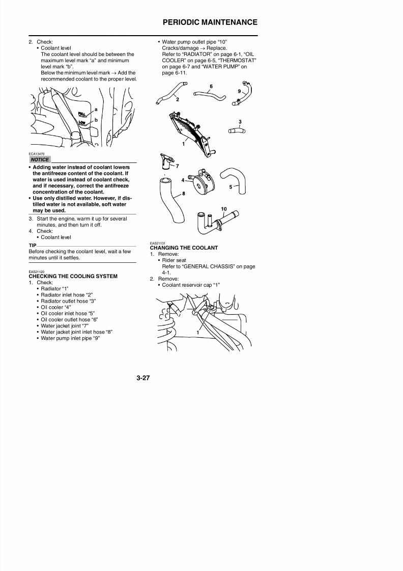
8/21/2019 Fz8 - Service Manual
http://slidepdf.com/reader/full/fz8-service-manual 156/609
ECA13470
• Adding water instead of coolant lowersthe antifreeze content of the coolant. Ifwater is used instead of coolant check,and if necessary, correct the antifreezeconcentration of the coolant.
• Use only distilled water. However, if dis-tilled water is not available, soft watermay be used.
3. Start the engine, warm it up for severalminutes, and then turn it off.
4. Check:• Coolant level
TIP
Before checking the coolant level, wait a fewminutes until it settles.
EAS21120
CHECKING THE COOLING SYSTEM1 Check:
EAS21131
CHANGING THE COOLANT1. Remove:
• Rider seat
Refer to “GENERAL CHASSIS” on page4-1.
2. Remove:C l i “ ”
PERIODIC MAINTENANCE
3. Remove:• Coolant reservoir tank
4. Disconnect:• Coolant reservoir hose
5. Drain:• Coolant(from the coolant reservoir)
6. Remove:• Radiator cap bolt “1”• Radiator cap “2”
WARNING
EWA13030
8. Drain:• Coolant
(from the engine and radiator)9. Install:
• Coolant drain bolt(along with the copper washer )
10.Connect:• Coolant reservoir hose
Coolant drain bolt7 Nm (0.7 m·kgf, 5.1 ft·lbf)
New
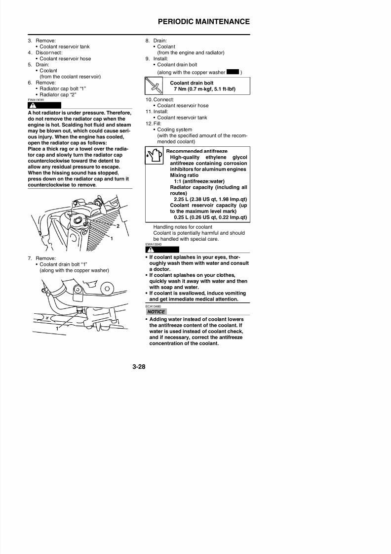
8/21/2019 Fz8 - Service Manual
http://slidepdf.com/reader/full/fz8-service-manual 157/609
A hot radiator is under pressure. Therefore,do not remove the radiator cap when theengine is hot. Scalding hot fluid and steammay be blown out, which could cause seri-ous injury. When the engine has cooled,open the radiator cap as follows:Place a thick rag or a towel over the radia-tor cap and slowly turn the radiator cap
counterclockwise toward the detent toallow any residual pressure to escape.When the hissing sound has stopped,press down on the radiator cap and turn itcounterclockwise to remove.
7. Remove:• Coolant drain bolt “1”(along with the copper washer)
11. Install:
• Coolant reservoir tank12.Fill:
• Cooling system(with the specified amount of the recom-mended coolant)
Handling notes for coolantCoolant is potentially harmful and shouldbe handled with special care.
WARNING
EWA13040
• If coolant splashes in your eyes, thor-oughly wash them with water and consulta doctor.
• If coolant splashes on your clothes
Recommended antifreezeHigh-quality ethylene glycol
antifreeze containing corrosioninhibitors for aluminum enginesMixing ratio
1:1 (antifreeze:water)Radiator capacity (including allroutes)
2.25 L (2.38 US qt, 1.98 Imp.qt)Coolant reservoir capacity (up
to the maximum level mark)0.25 L (0.26 US qt, 0.22 Imp.qt)
PERIODIC MAINTENANCE
• Use only distilled water. However, if dis-tilled water is not available, soft watermay be used.
• If coolant comes into contact with painted
surfaces, immediately wash them withwater.• Do not mix different types of antifreeze.
13. Install:• Radiator cap• Radiator cap bolt
EAS21330
ADJUSTING THE REAR BRAKE LIGHTSWITCH
TIP
The rear brake light switch is operated bymovement of the brake pedal. The rear brakelight switch is properly adjusted when the
brake light comes on just before the brakingeffect starts.
1. Check:• Rear brake light operation timing
I t Adj tRadiator cap bolt
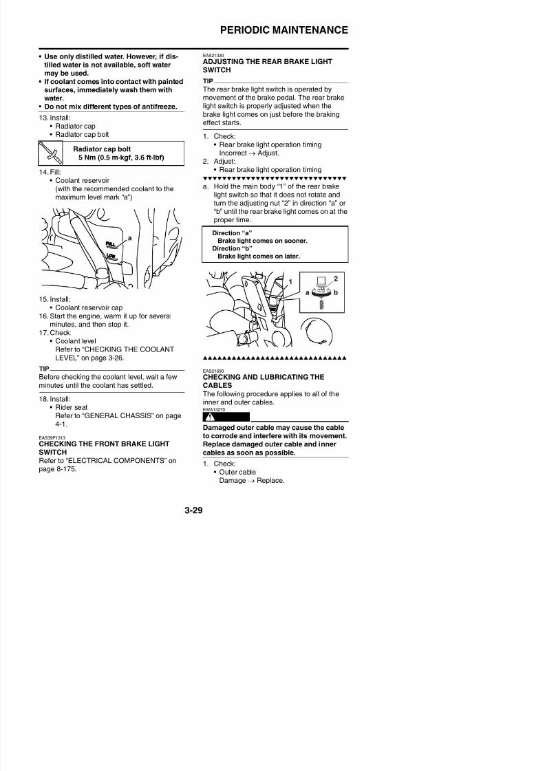
8/21/2019 Fz8 - Service Manual
http://slidepdf.com/reader/full/fz8-service-manual 158/609
14.Fill:• Coolant reservoir
(with the recommended coolant to themaximum level mark “a”)
15. Install:• Coolant reservoir cap
16. Start the engine, warm it up for severalminutes, and then stop it.
17.Check:• Coolant level
Refer to “CHECKING THE COOLANTLEVEL” on page 3-26.
TIP
Before checking the coolant level, wait a few
Incorrect → Adjust.
2. Adjust:• Rear brake light operation timing
a. Hold the main body “1” of the rear brakelight switch so that it does not rotate andturn the adjusting nut “2” in direction “a” or“b” until the rear brake light comes on at theproper time.
EAS21690
CHECKING AND LUBRICATING THE
Radiator cap bolt
5 Nm (0.5 m·kgf, 3.6 ft·lbf)
Direction “a”Brake light comes on sooner.
Direction “b”Brake light comes on later.
PERIODIC MAINTENANCE
2. Check:• Cable operation
Rough movement → Lubricate.
TIP
Hold the cable end upright and pour a fewdrops of lubricant into the cable sheath or usea suitable lubricating device.
c. Tighten the locknut “1”.
Recommended lubricant
Engine oil or a suitable cablelubricant
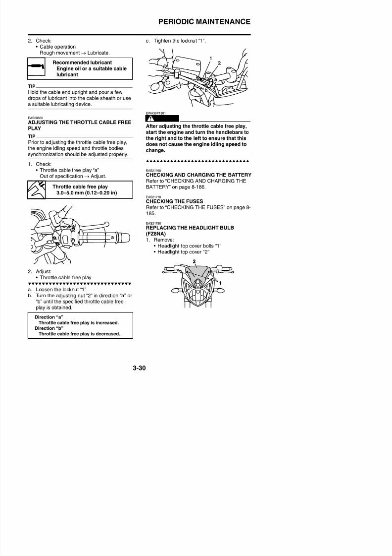
8/21/2019 Fz8 - Service Manual
http://slidepdf.com/reader/full/fz8-service-manual 159/609
EAS20630
ADJUSTING THE THROTTLE CABLE FREEPLAY
TIP
Prior to adjusting the throttle cable free play,the engine idling speed and throttle bodiessynchronization should be adjusted properly.
1. Check:• Throttle cable free play “a”
Out of specification → Adjust.
2. Adjust:Th l bl f l
WARNING
EWA39P1301
After adjusting the throttle cable free play,start the engine and turn the handlebars tothe right and to the left to ensure that thisdoes not cause the engine idling speed tochange.
EAS21760
CHECKING AND CHARGING THE BATTERYRefer to “CHECKING AND CHARGING THEBATTERY” on page 8-186.
EAS21770
CHECKING THE FUSESRefer to “CHECKING THE FUSES” on page 8-
185.
EAS21790
REPLACING THE HEADLIGHT BULB(FZ8NA)1. Remove:
• Headlight top cover bolts “1”• Headlight top cover “2”
Throttle cable free play3.0–5.0 mm (0.12–0.20 in)
PERIODIC MAINTENANCE
2. Remove:• Headlight bolt “1”
6. Remove:• Headlight bulb holder “1”
EWA13320
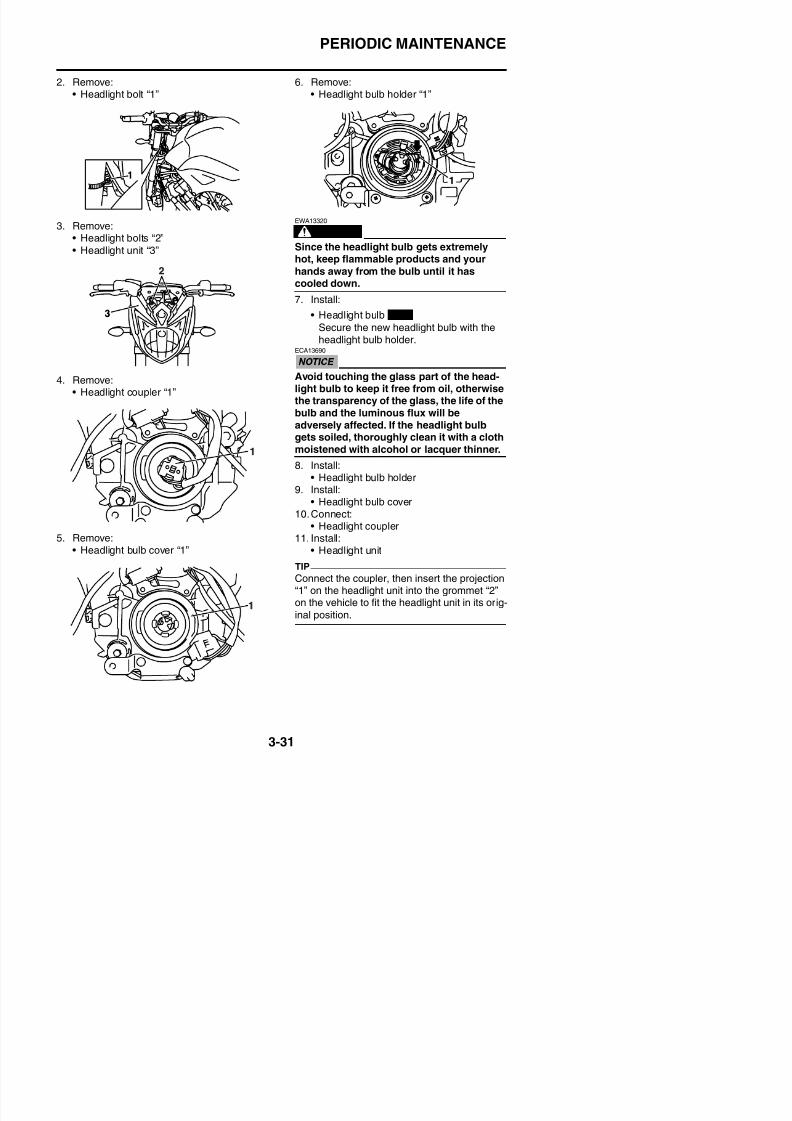
8/21/2019 Fz8 - Service Manual
http://slidepdf.com/reader/full/fz8-service-manual 160/609
3. Remove:• Headlight bolts “2”
• Headlight unit “3”
4. Remove:• Headlight coupler “1”
5. Remove:• Headlight bulb cover “1”
WARNING
EWA13320
Since the headlight bulb gets extremelyhot, keep flammable products and your
hands away from the bulb until it hascooled down.
7. Install:
• Headlight bulb
Secure the new headlight bulb with theheadlight bulb holder.ECA13690
Avoid touching the glass part of the head-light bulb to keep it free from oil, otherwisethe transparency of the glass, the life of thebulb and the luminous flux will be
adversely affected. If the headlight bulbgets soiled, thoroughly clean it with a clothmoistened with alcohol or lacquer thinner.
8. Install:• Headlight bulb holder
9. Install:• Headlight bulb cover
10.Connect:
• Headlight coupler11. Install:
• Headlight unit
New
PERIODIC MAINTENANCE
12. Install:• Headlight bolts
3. Remove:H dli ht b lb “1”
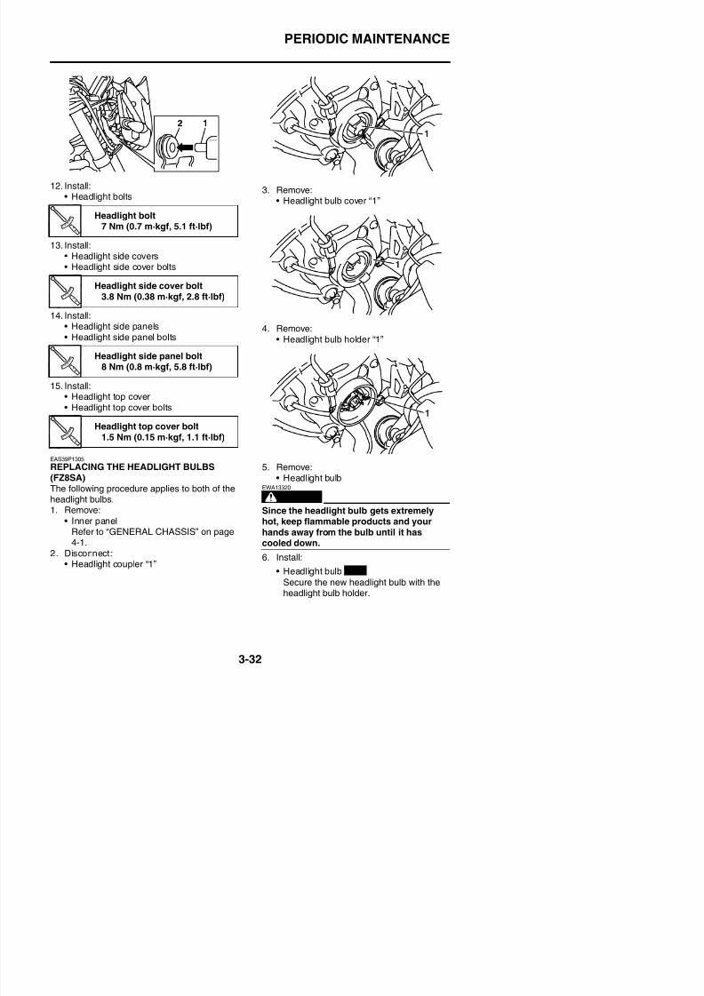
8/21/2019 Fz8 - Service Manual
http://slidepdf.com/reader/full/fz8-service-manual 161/609
Headlight bolts
13. Install:• Headlight side covers• Headlight side cover bolts
14. Install:• Headlight side panels• Headlight side panel bolts
15. Install:• Headlight top cover• Headlight top cover bolts
EAS39P1305
REPLACING THE HEADLIGHT BULBS(FZ8SA)The following procedure applies to both of the
• Headlight bulb cover “1”
4. Remove:• Headlight bulb holder “1”
5. Remove:• Headlight bulb
EWA13320
Headlight bolt7 Nm (0.7 m·kgf, 5.1 ft·lbf)
Headlight side cover bolt
3.8 Nm (0.38 m·kgf, 2.8 ft·lbf)
Headlight side panel bolt8 Nm (0.8 m·kgf, 5.8 ft·lbf)
Headlight top cover bolt1.5 Nm (0.15 m·kgf, 1.1 ft·lbf)
PERIODIC MAINTENANCE
ECA13690
Avoid touching the glass part of the head-light bulb to keep it free from oil, otherwisethe transparency of the glass, the life of thebulb and the luminous flux will beadversely affected. If the headlight bulbgets soiled, thoroughly clean it with a cloth
moistened with alcohol or lacquer thinner.
7. Install:• Headlight bulb holder
8. Install:
Direction “a”Headlight beam moves to the right.
Direction “b”Headlight beam moves to the left.
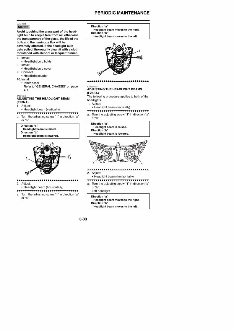
8/21/2019 Fz8 - Service Manual
http://slidepdf.com/reader/full/fz8-service-manual 162/609
• Headlight bulb cover9. Connect:
• Headlight coupler10. Install:
• Inner panelRefer to “GENERAL CHASSIS” on page4-1.
EAS21810
ADJUSTING THE HEADLIGHT BEAM(FZ8NA)1. Adjust:
• Headlight beam (vertically)
a. Turn the adjusting screw “1” in direction “a”or “b”.
EAS39P1314
ADJUSTING THE HEADLIGHT BEAMS
(FZ8SA)
The following procedure applies to both of theheadlights.1. Adjust:
• Headlight beam (vertically)
a. Turn the adjusting screw “1” in direction “a”or “b”.
Direction “a”Headlight beam is raised.Direction “b”
Headlight beam is lowered.
Direction “a”
Headlight beam is raised.Direction “b”
Headlight beam is lowered.
PERIODIC MAINTENANCE
Right headlight
Direction “a”Headlight beam moves to the left.
Direction “b”
Headlight beam moves to the right.
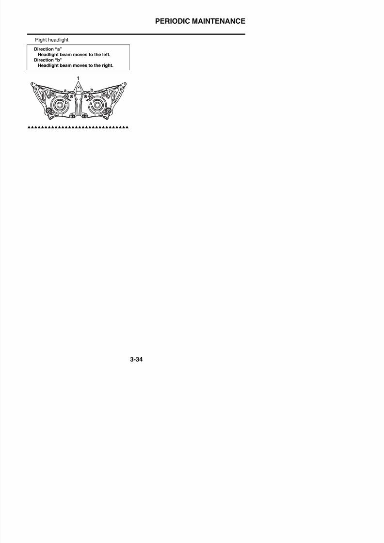
8/21/2019 Fz8 - Service Manual
http://slidepdf.com/reader/full/fz8-service-manual 163/609
PERIODIC MAINTENANCE

8/21/2019 Fz8 - Service Manual
http://slidepdf.com/reader/full/fz8-service-manual 164/609
CHASSIS
GENERAL CHASSIS....................................................................................4-1REMOVING THE INNER PANEL (FZ8SA) .............................................4-9INSTALLING THE INNER PANEL (FZ8SA)............................................4-9REMOVING THE SIDE PANEL (FZ8SA)................................................4-9INSTALLING THE SIDE PANEL (FZ8SA)...............................................4-9REMOVING THE FRONT COWLING SIDE PANEL (FZ8SA)............... 4-10INSTALLING THE FRONT COWLING SIDE PANEL (FZ8SA) .............4-10INSTALLING THE HEADLIGHT ASSEMBLY (FZ8SA) .........................4-11
8/21/2019 Fz8 - Service Manual
http://slidepdf.com/reader/full/fz8-service-manual 165/609
4
FRONT WHEEL ..........................................................................................4-12REMOVING THE FRONT WHEEL .......................................................4-14CHECKING THE FRONT WHEEL........................................................4-14DISASSEMBLING THE FRONT WHEEL .............................................4-14ASSEMBLING THE FRONT WHEEL ...................................................4-15MAINTENANCE OF THE FRONT WHEEL SENSOR AND SENSORROTOR .................................................................................................4-15ADJUSTING THE FRONT WHEEL STATIC BALANCE .......................4-18
INSTALLING THE FRONT WHEEL (FRONT BRAKE DISCS) .............4-19
REAR WHEEL ............................................................................................4-21REMOVING THE REAR WHEEL .........................................................4-24CHECKING THE REAR WHEEL..........................................................4-24DISASSEMBLING THE REAR WHEEL ...............................................4-24CHECKING THE REAR WHEEL DRIVE HUB ..................................... 4-24CHECKING AND REPLACING THE REAR WHEEL SPROCKET.......4-25ASSEMBLING THE REAR WHEEL .....................................................4-25MAINTENANCE OF THE REAR WHEEL SENSOR AND SENSORROTOR .................................................................................................4-25ADJUSTING THE REAR WHEEL STATIC BALANCE.......................... 4-28INSTALLING THE REAR WHEEL (REAR BRAKE DISC) ....................4-28
FRONT BRAKE ..........................................................................................4-30
INTRODUCTION ..................................................................................4-35CHECKING THE FRONT BRAKE DISCS ............................................4-35REPLACING THE FRONT BRAKE PADS ............................................4-36
REAR BRAKE ............................................................................................4-43INTRODUCTION ..................................................................................4-49CHECKING THE REAR BRAKE DISC.................................................4-49REPLACING THE REAR BRAKE PADS ..............................................4-49REMOVING THE REAR BRAKE CALIPER..........................................4-51DISASSEMBLING THE REAR BRAKE CALIPER................................4-51CHECKING THE REAR BRAKE CALIPER ..........................................4-51ASSEMBLING THE REAR BRAKE CALIPER......................................4-52INSTALLING THE REAR BRAKE CALIPER.........................................4-52REMOVING THE REAR BRAKE MASTER CYLINDER.......................4-53CHECKING THE REAR BRAKE MASTER CYLINDER ....................... 4-54ASSEMBLING THE REAR BRAKE MASTER CYLINDER...................4-54INSTALLING THE REAR BRAKE MASTER CYLINDER......................4-54
8/21/2019 Fz8 - Service Manual
http://slidepdf.com/reader/full/fz8-service-manual 166/609
INSTALLING THE REAR BRAKE MASTER CYLINDER......................4 54
ABS (ANTI-LOCK BRAKE SYSTEM) ........................................................4-56REMOVING THE HYDRAULIC UNIT ASSEMBLY ...............................4-58CHECKING THE HYDRAULIC UNIT ASSEMBLY................................4-58CHECKING THE BRAKE PIPES..........................................................4-59INSTALLING THE HYDRAULIC UNIT ASSEMBLY .............................. 4-59HYDRAULIC UNIT OPERATION TESTS..............................................4-60
TRIAL RUN...........................................................................................4-63
HANDLEBAR..............................................................................................4-64REMOVING THE HANDLEBAR ...........................................................4-66CHECKING THE HANDLEBAR............................................................4-66INSTALLING THE HANDLEBAR ..........................................................4-66
FRONT FORK .............................................................................................4-69REMOVING THE FRONT FORK LEGS ...............................................4-71DISASSEMBLING THE FRONT FORK LEGS .....................................4-71
CHECKING THE FRONT FORK LEGS................................................4-72ASSEMBLING THE FRONT FORK LEGS ...........................................4-73INSTALLING THE FRONT FORK LEGS ..............................................4-77
STEERING HEAD.......................................................................................4-78REMOVING THE LOWER BRACKET ..................................................4-82CHECKING THE STEERING HEAD ....................................................4-82INSTALLING THE STEERING HEAD 4 83
SWINGARM ................................................................................................4-88REMOVING THE SWINGARM .............................................................4-89CHECKING THE SWINGARM .............................................................4-89INSTALLING THE SWINGARM............................................................4-90
CHAIN DRIVE .............................................................................................4-91REMOVING THE DRIVE CHAIN ..........................................................4-92CHECKING THE DRIVE CHAIN ..........................................................4-92
CHECKING THE DRIVE SPROCKET..................................................4-93CHECKING THE REAR WHEEL SPROCKET ..................................... 4-93CHECKING THE REAR WHEEL DRIVE HUB ..................................... 4-93INSTALLING THE DRIVE CHAIN.........................................................4-94

8/21/2019 Fz8 - Service Manual
http://slidepdf.com/reader/full/fz8-service-manual 167/609
GENERAL CHASSIS
EAS21830
GENERAL CHASSIS
Removing the seat and battery
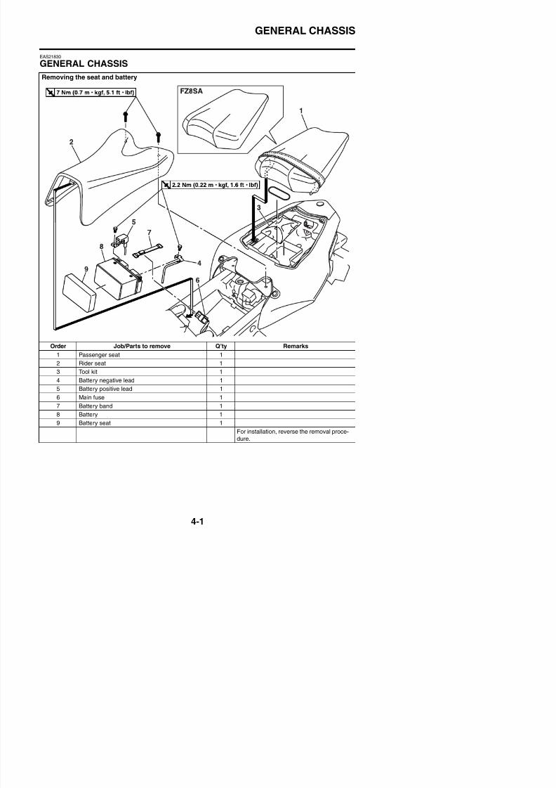
8/21/2019 Fz8 - Service Manual
http://slidepdf.com/reader/full/fz8-service-manual 168/609
Order Job/Parts to remove Q’ty Remarks
1 Passenger seat 1
2 Rider seat 1
3 Tool kit 14 Battery negative lead 1
5 Battery positive lead 1
GENERAL CHASSIS
Removing the headlight and meter assembly (FZ8NA)
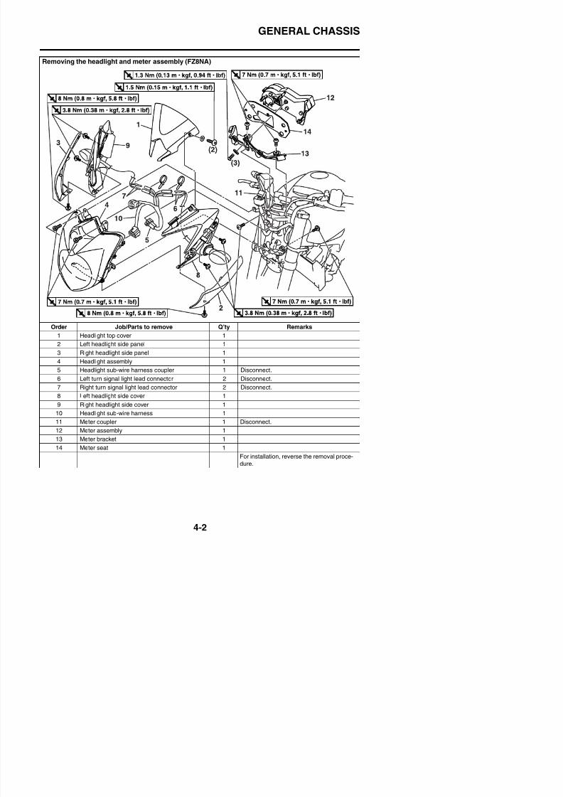
8/21/2019 Fz8 - Service Manual
http://slidepdf.com/reader/full/fz8-service-manual 169/609
Order Job/Parts to remove Q’ty Remarks
1 Headlight top cover 1
2 Left headlight side panel 1
3 Right headlight side panel 1
4 Headlight assembly 1
5 Headlight sub-wire harness coupler 1 Disconnect.
6 Left turn signal light lead connector 2 Disconnect.
7 Right turn signal light lead connector 2 Disconnect.
8 Left headlight side cover 1
GENERAL CHASSIS
Removing the front cowling assembly (FZ8SA)
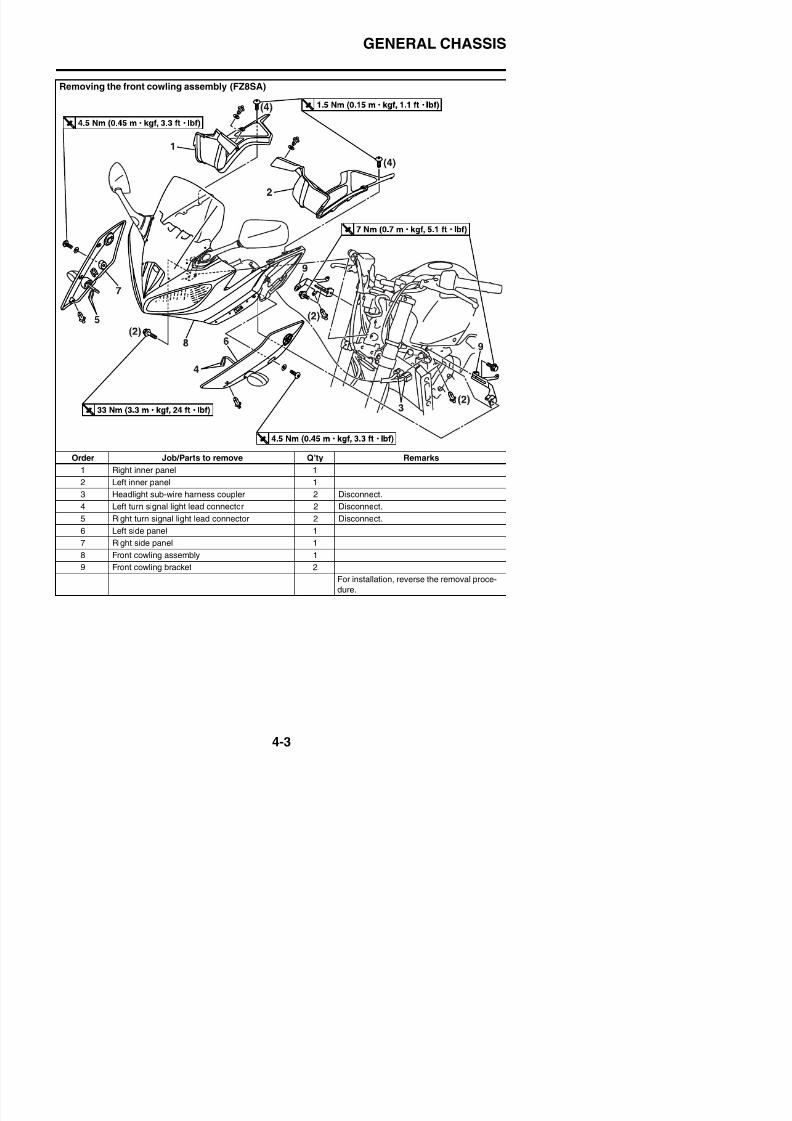
8/21/2019 Fz8 - Service Manual
http://slidepdf.com/reader/full/fz8-service-manual 170/609
Order Job/Parts to remove Q’ty Remarks
1 Right inner panel 1
2 Left inner panel 1
3 Headlight sub-wire harness coupler 2 Disconnect.
4 Left turn signal light lead connector 2 Disconnect.
5 Right turn signal light lead connector 2 Disconnect.
6 Left side panel 1
7 Right side panel 1
8 Front cowling assembly 1
GENERAL CHASSIS
Disassembling the front cowling assembly (FZ8SA)
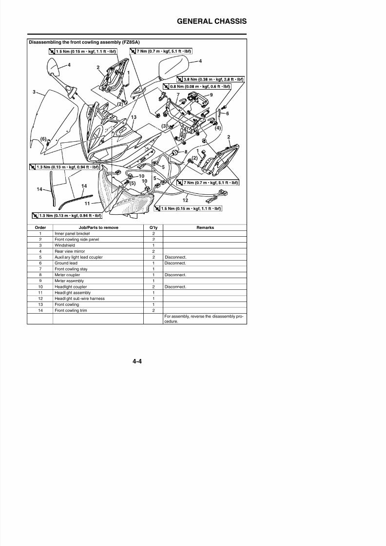
8/21/2019 Fz8 - Service Manual
http://slidepdf.com/reader/full/fz8-service-manual 171/609
Order Job/Parts to remove Q’ty Remarks
1 Inner panel bracket 2
2 Front cowling side panel 2
3 Windshield 1
4 Rear view mirror 2
5 Auxiliary light lead coupler 2 Disconnect.6 Ground lead 1 Disconnect.
7 Front cowling stay 1
GENERAL CHASSIS
Removing the under cowling
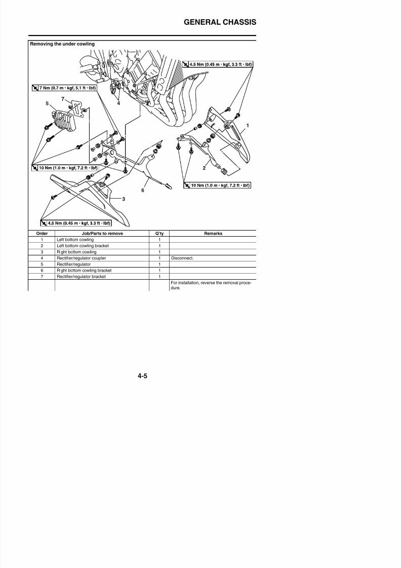
8/21/2019 Fz8 - Service Manual
http://slidepdf.com/reader/full/fz8-service-manual 172/609
Order Job/Parts to remove Q’ty Remarks
1 Left bottom cowling 1
2 Left bottom cowling bracket 1
3 Right bottom cowling 1
4 Rectifier/regulator coupler 1 Disconnect.
5 Rectifier/regulator 1
6 Right bottom cowling bracket 1
7 Rectifier/regulator bracket 1
F i t ll ti th l
GENERAL CHASSIS
Removing the rear cover (FZ8NA)
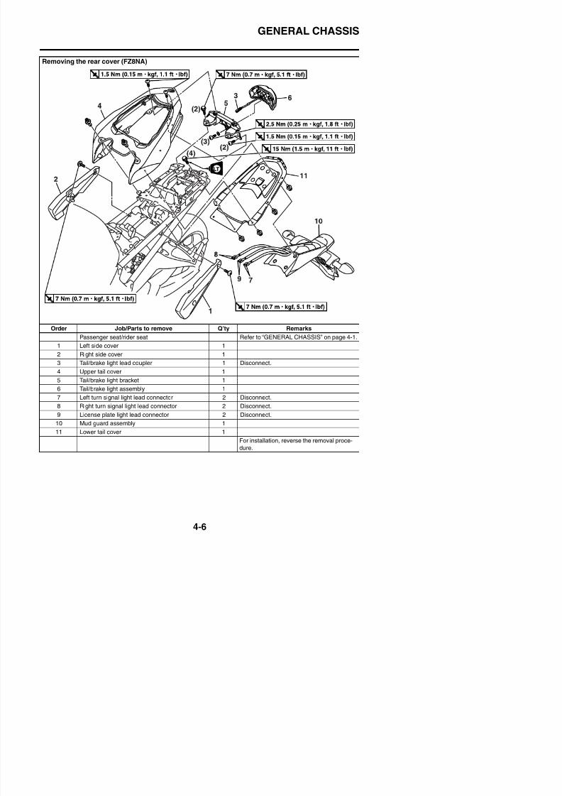
8/21/2019 Fz8 - Service Manual
http://slidepdf.com/reader/full/fz8-service-manual 173/609
Order Job/Parts to remove Q’ty Remarks
Passenger seat/rider seat Refer to “GENERAL CHASSIS” on page 4-1.
1 Left side cover 1
2 Right side cover 1
3 Tail/brake light lead coupler 1 Disconnect.
4 Upper tail cover 1
5 Tail/brake light bracket 1
6 Tail/brake light assembly 1
GENERAL CHASSIS
Removing the rear cover (FZ8SA)
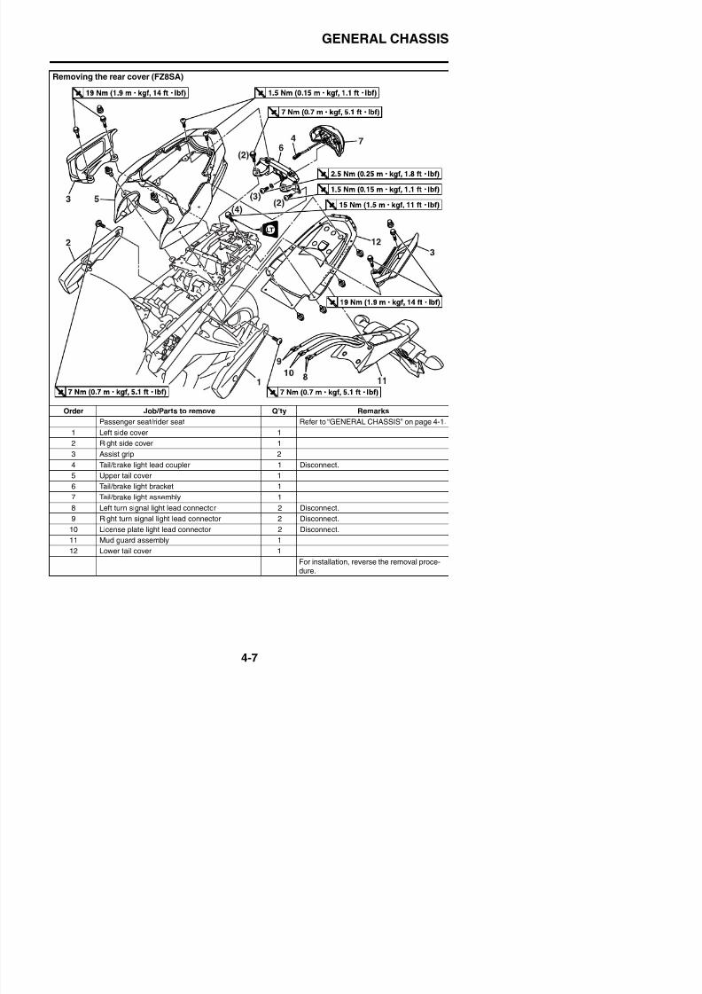
8/21/2019 Fz8 - Service Manual
http://slidepdf.com/reader/full/fz8-service-manual 174/609
Order Job/Parts to remove Q’ty Remarks
Passenger seat/rider seat Refer to “GENERAL CHASSIS” on page 4-1.
1 Left side cover 1
2 Right side cover 1
3 Assist grip 2
4 Tail/brake light lead coupler 1 Disconnect.
5 Upper tail cover 1
6 Tail/brake light bracket 1
GENERAL CHASSIS
Removing the air filter case
2.0 Nm (0.20 m kgf, 1.5 ft Ibf)T R
.
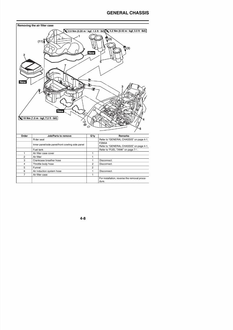
8/21/2019 Fz8 - Service Manual
http://slidepdf.com/reader/full/fz8-service-manual 175/609
Order Job/Parts to remove Q’ty Remarks
Rider seat Refer to “GENERAL CHASSIS” on page 4-1.
Inner panel/side panel/front cowling side panelFZ8SA
Refer to “GENERAL CHASSIS” on page 4-1.
Fuel tank Refer to “FUEL TANK” on page 7-1.
1 Air filter case cover 1
2 Air filter 1
3 Crankcase breather hose 1 Disconnect.
4 Throttle body hose 2 Disconnect
GENERAL CHASSIS
EAS39P1404
REMOVING THE INNER PANEL (FZ8SA)1. Remove:
• Inner panel “1”
a. First remove the right inner panel, and thenremove the left inner panel.
b. Remove the quick fastener and the bolts.
c. Slightly lift the rear of the inner panel andthen disengage projections “a”.
d. Disengage projections “b”, sliding the innerpanel obliquely backward as shown in theillustration, and then remove the inner
panel.
d. Press the rear of the inner panel downwardto engage projections “b”.
e. Install the quick fastener and bolts.
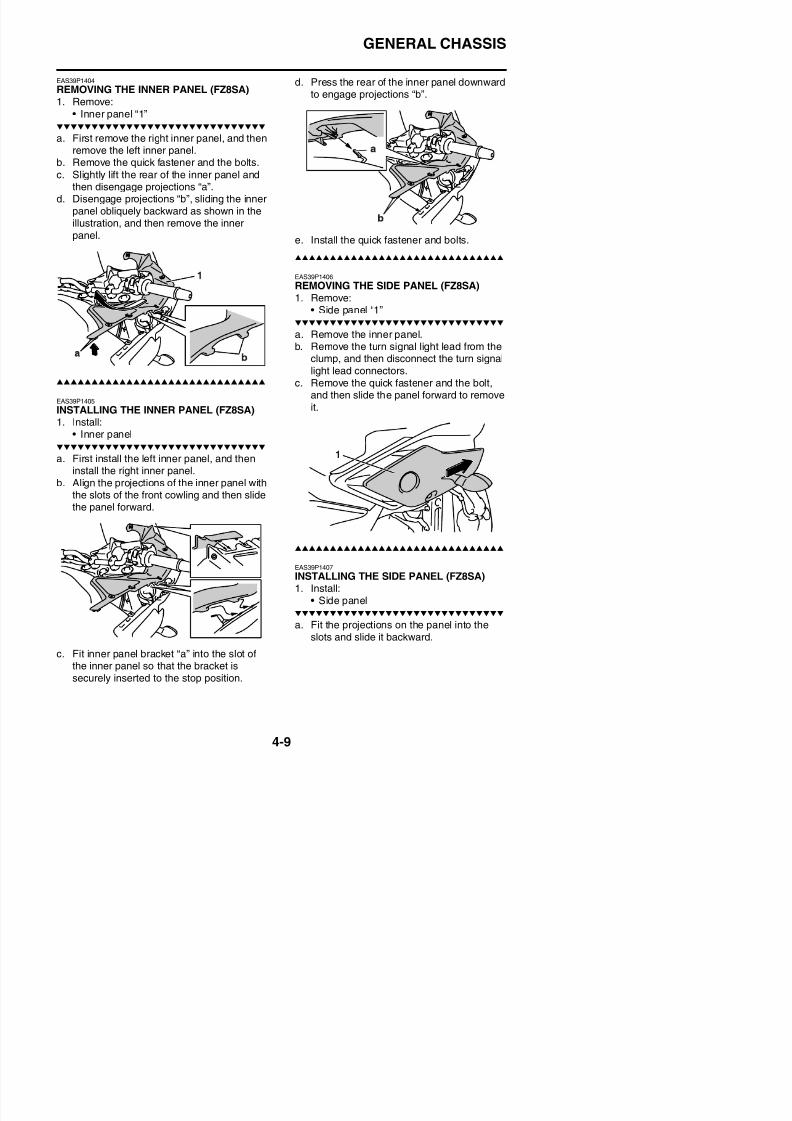
8/21/2019 Fz8 - Service Manual
http://slidepdf.com/reader/full/fz8-service-manual 176/609
panel.
EAS39P1405
INSTALLING THE INNER PANEL (FZ8SA)1. Install:
• Inner panel
a. First install the left inner panel, and theninstall the right inner panel.
b. Align the projections of the inner panel withthe slots of the front cowling and then slidethe panel forward.
e. Install the quick fastener and bolts.
EAS39P1406
REMOVING THE SIDE PANEL (FZ8SA)1. Remove:
• Side panel “1”
a. Remove the inner panel.b. Remove the turn signal light lead from the
clump, and then disconnect the turn signallight lead connectors.
c. Remove the quick fastener and the bolt,and then slide the panel forward to removeit.
1
GENERAL CHASSIS
b. Install the quick fastener and bolt.c. Connect the turn signal light connectors.
d. Fasten headlight sub-wire harness “1” and
EAS39P1409
INSTALLING THE FRONT COWLING SIDE
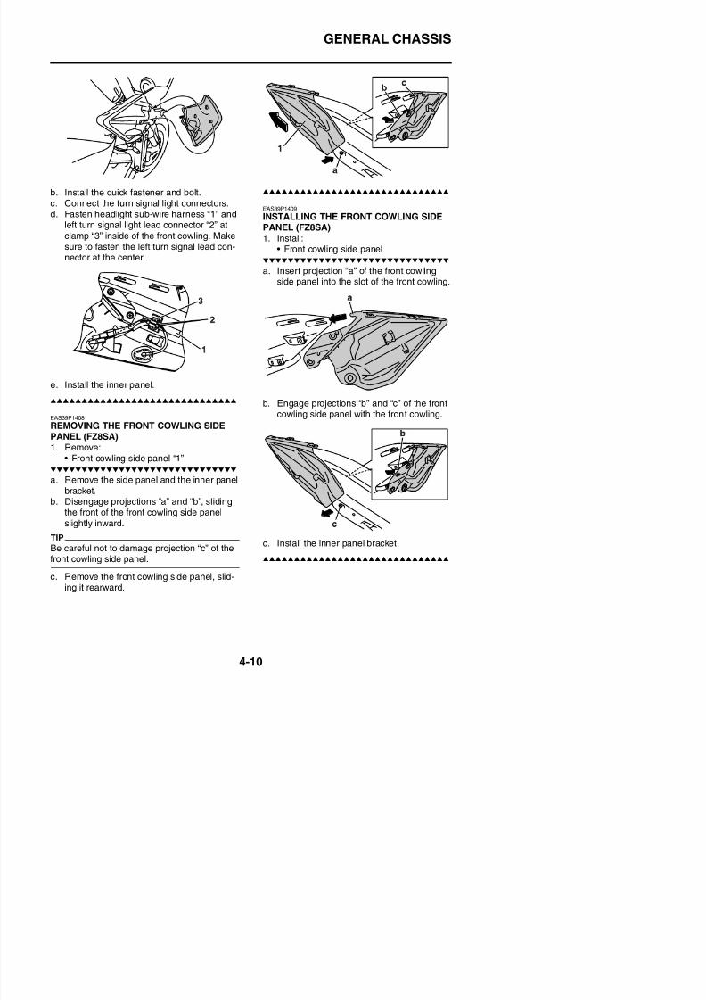
8/21/2019 Fz8 - Service Manual
http://slidepdf.com/reader/full/fz8-service-manual 177/609
gleft turn signal light lead connector “2” atclamp “3” inside of the front cowling. Makesure to fasten the left turn signal lead con-nector at the center.
e. Install the inner panel.
EAS39P1408
REMOVING THE FRONT COWLING SIDEPANEL (FZ8SA)1. Remove:
• Front cowling side panel “1”
a. Remove the side panel and the inner panelbracket.
INSTALLING THE FRONT COWLING SIDEPANEL (FZ8SA)1. Install:
• Front cowling side panel
a. Insert projection “a” of the front cowlingside panel into the slot of the front cowling.
b. Engage projections “b” and “c” of the frontcowling side panel with the front cowling.
GENERAL CHASSIS
EAS39P1410
INSTALLING THE HEADLIGHT ASSEMBLY(FZ8SA)1. Install:
• Headlight assembly
a. Temporarily tighten the screw “1”.b. Tighten the screw “2”.
c. Tighten the screw “1”.d. Tighten the screws “3” not specified can be
in any order.
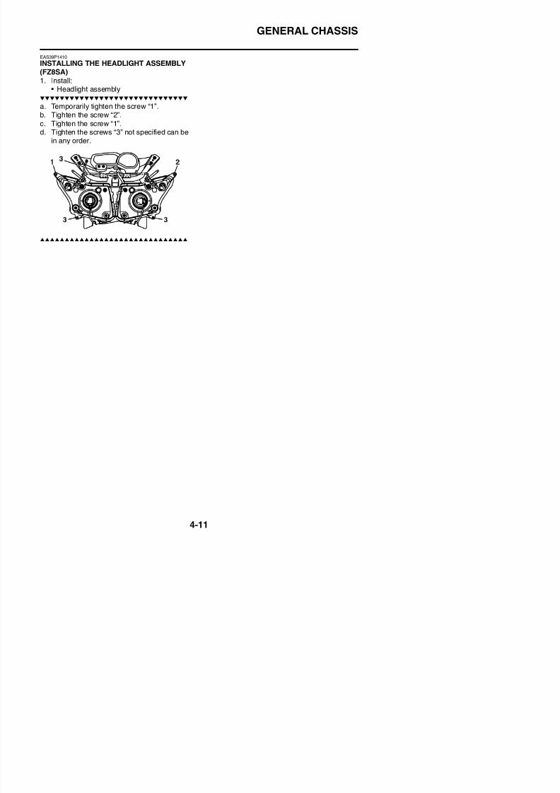
8/21/2019 Fz8 - Service Manual
http://slidepdf.com/reader/full/fz8-service-manual 178/609
FRONT WHEEL
EAS21870
FRONT WHEEL
Removing the front wheel and brake discs
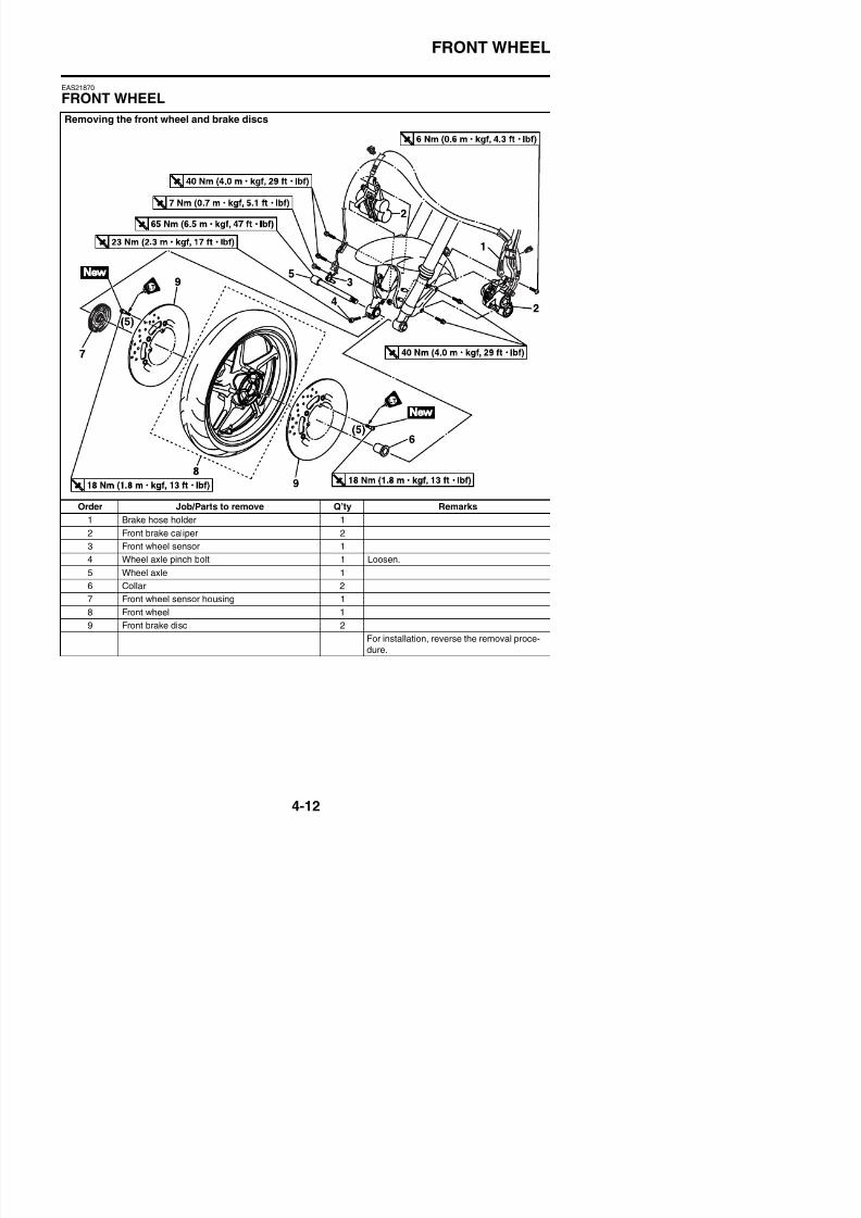
8/21/2019 Fz8 - Service Manual
http://slidepdf.com/reader/full/fz8-service-manual 179/609
Order Job/Parts to remove Q’ty Remarks
1 Brake hose holder 1
2 Front brake caliper 2
3 Front wheel sensor 1
4 Wheel axle pinch bolt 1 Loosen.
5 Wheel axle 16 Collar 2
7 Front wheel sensor housing 1
FRONT WHEEL
Disassembling the front wheel
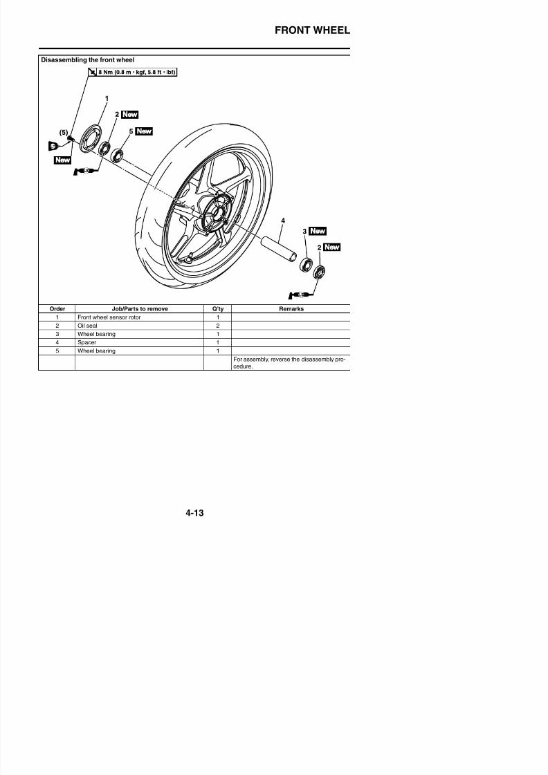
8/21/2019 Fz8 - Service Manual
http://slidepdf.com/reader/full/fz8-service-manual 180/609
Order Job/Parts to remove Q’ty Remarks
1 Front wheel sensor rotor 1
2 Oil seal 2
3 Wheel bearing 1
4 Spacer 1
5 Wheel bearing 1
For assembly, reverse the disassembly pro-
cedure.
FRONT WHEEL
EAS21900
REMOVING THE FRONT WHEEL1. Stand the vehicle on a level surface.
WARNING
EWA13120
Securely support the vehicle so that thereis no danger of it falling over.
2. Remove:• Left brake caliper• Right brake caliper• Front wheel sensor
TIP
Do not apply the brake lever when removingthe brake calipers.
3. Measure:• Radial wheel runout “1”• Lateral wheel runout “2”
Over the specified limits → Replace.
Radial wheel runout limit1.0 mm (0.04 in)Lateral wheel runout limit
0.5 mm (0.02 in)

8/21/2019 Fz8 - Service Manual
http://slidepdf.com/reader/full/fz8-service-manual 181/609
3. Elevate:• Front wheel
TIP
Place the vehicle on a suitable stand so thatthe front wheel is elevated.
4. Loosen:• Wheel axle pinch bolt
5. Remove:• Wheel axle• Front wheel
EAS21922
CHECKING THE FRONT WHEEL1. Check:
• Wheel axleRoll the wheel axle on a flat surface.Bends → Replace.
WARNING
EWA13460
Do not attempt to straighten a bent wheelaxle.
4. Check:• Wheel bearings
Front wheel turns roughly or is loose → Replace the wheel bearings.
• Oil sealDamage/wear → Replace.
EAS21910
DISASSEMBLING THE FRONT WHEEL
1. Remove:• Oil seals
• Wheel bearings
FRONT WHEEL
c. Remove the wheel bearings “3” with a gen-eral bearing puller.
b. Install the spacer.c. Install the new wheel bearing (left side).
TIP
Place a suitable washer “1” between thesocket “2” and the bearing so that both theinner race “3” and outer race “4” are pressed atthe same time, and then press the bearing untilthe inner race makes contact with the spacer“5”.
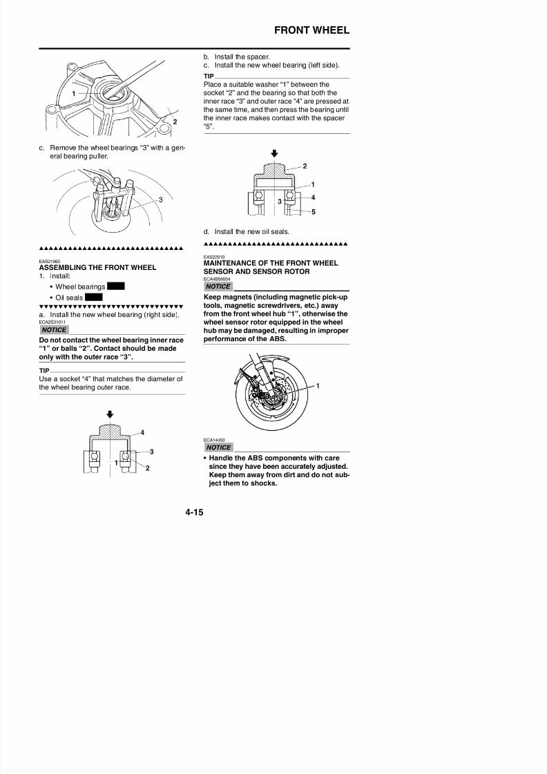
8/21/2019 Fz8 - Service Manual
http://slidepdf.com/reader/full/fz8-service-manual 182/609
EAS21960
ASSEMBLING THE FRONT WHEEL1. Install:
• Wheel bearings
• Oil seals
a. Install the new wheel bearing (right side).ECA2S31011
Do not contact the wheel bearing inner race“1” or balls “2”. Contact should be made
only with the outer race “3”.
TIP
Use a socket “4” that matches the diameter of
d. Install the new oil seals.
EAS22010
MAINTENANCE OF THE FRONT WHEELSENSOR AND SENSOR ROTORECA4B56004
Keep magnets (including magnetic pick-uptools, magnetic screwdrivers, etc.) awayfrom the front wheel hub “1”, otherwise thewheel sensor rotor equipped in the wheelhub may be damaged, resulting in improperperformance of the ABS.
New
New
FRONT WHEEL
• The ABS wheel sensor cannot be disas-sembled. Do not attempt to disassembleit. If faulty, replace with a new one.
Removing the front wheel sensor
1. Disconnect:• Front wheel sensor coupler “1”
2. Check:• Front wheel sensor rotor
Cracks/damage → Replace.3. Measure:
Wh l t d fl ti
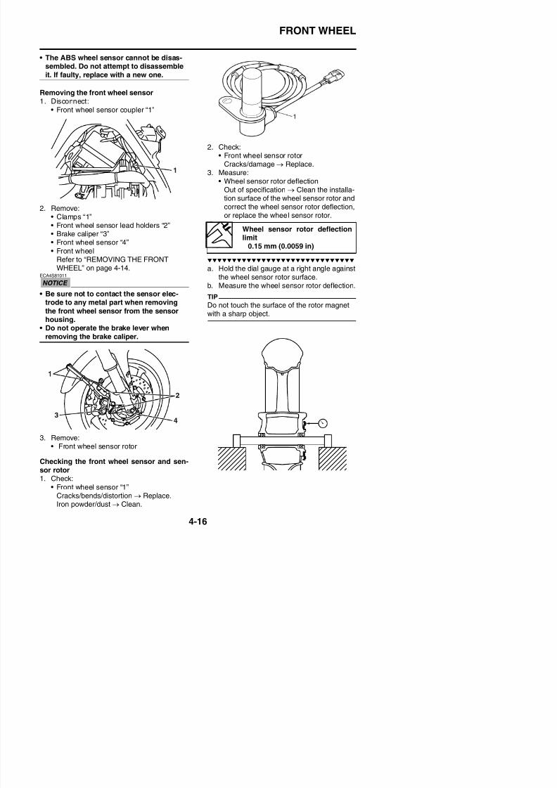
8/21/2019 Fz8 - Service Manual
http://slidepdf.com/reader/full/fz8-service-manual 183/609
2. Remove:• Clamps “1”• Front wheel sensor lead holders “2”
• Brake caliper “3”• Front wheel sensor “4”
• Front wheelRefer to “REMOVING THE FRONTWHEEL” on page 4-14.
ECA4S81011
• Be sure not to contact the sensor elec-
trode to any metal part when removingthe front wheel sensor from the sensorhousing.
• Do not operate the brake lever whenremoving the brake caliper.
• Wheel sensor rotor deflectionOut of specification → Clean the installa-tion surface of the wheel sensor rotor andcorrect the wheel sensor rotor deflection,or replace the wheel sensor rotor.
a. Hold the dial gauge at a right angle againstthe wheel sensor rotor surface.
b. Measure the wheel sensor rotor deflection.
TIP
Do not touch the surface of the rotor magnetwith a sharp object.
Wheel sensor rotor deflection
limit0.15 mm (0.0059 in)
FRONT WHEEL
c. If the deflection is above specification,replace the wheel sensor.
ECA4B56023
Replace the wheel sensor rotor bolts withnew ones.
d. If the deflection is still above specification,replace the wheel sensor rotor.
Wheel sensor rotor bolt8 Nm (0.8 m·kgf, 5.8 ft·lbf)
LOCTITE®
Distance “a” (between thewheel sensor rotor and wheelsensor housing)
29.53–30.25 mm (1.16–1.19 in)
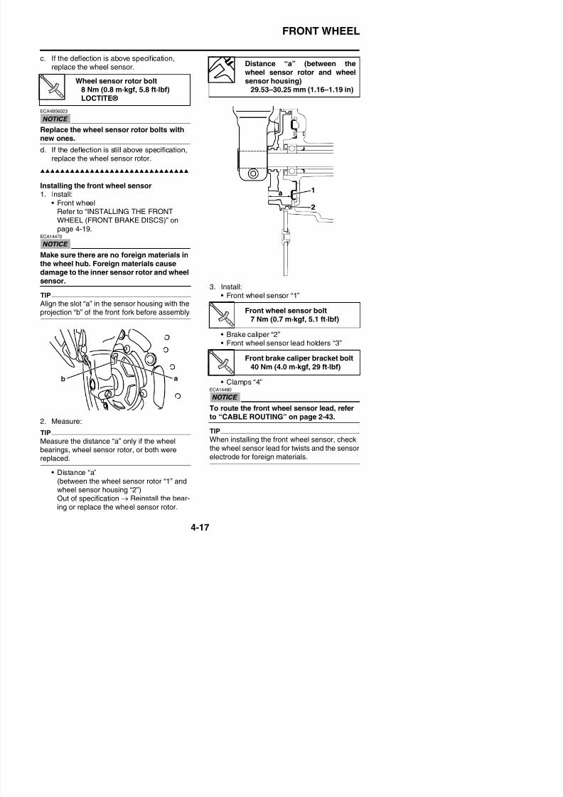
8/21/2019 Fz8 - Service Manual
http://slidepdf.com/reader/full/fz8-service-manual 184/609
Installing the front wheel sensor1. Install:
• Front wheelRefer to “INSTALLING THE FRONTWHEEL (FRONT BRAKE DISCS)” onpage 4-19.
ECA14470
Make sure there are no foreign materials inthe wheel hub. Foreign materials causedamage to the inner sensor rotor and wheelsensor.
TIP
Align the slot “a” in the sensor housing with theprojection “b” of the front fork before assembly.
3. Install:• Front wheel sensor “1”
• Brake caliper “2”• Front wheel sensor lead holders “3”
• Clamps “4”ECA14480
Front wheel sensor bolt7 Nm (0.7 m·kgf, 5.1 ft·lbf)
Front brake caliper bracket bolt40 Nm (4.0 m·kgf, 29 ft·lbf)
FRONT WHEEL
4. Connect:• Front wheel sensor coupler “1”
c. Turn the front wheel 90° so that the “X1”
mark is positioned as shown.d. Release the front wheel.
e. When the wheel stops, put an “X2” mark atthe bottom of the wheel
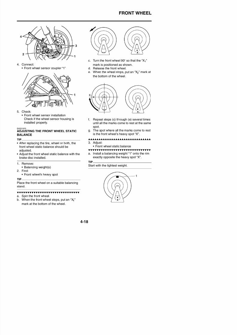
8/21/2019 Fz8 - Service Manual
http://slidepdf.com/reader/full/fz8-service-manual 185/609
5. Check:• Front wheel sensor installation
Check if the wheel sensor housing isinstalled properly.
EAS21970
ADJUSTING THE FRONT WHEEL STATICBALANCE
TIP
• After replacing the tire, wheel or both, thefront wheel static balance should beadjusted.
• Adjust the front wheel static balance with the
brake disc installed.1. Remove:
( )
the bottom of the wheel.
f. Repeat steps (c) through (e) several timesuntil all the marks come to rest at the samespot.
g. The spot where all the marks come to restis the front wheel’s heavy spot “X”.
3. Adjust:• Front wheel static balance
a. Install a balancing weight “1” onto the rimexactly opposite the heavy spot “X”.
TIP
Start with the lightest weight
FRONT WHEEL
b. Turn the front wheel 90° so that the heavyspot is positioned as shown.
c. If the heavy spot does not stay in that posi-
tion, install a heavier weight.d. Repeat steps (b) and (c) until the front
2. Check:• Front brake discs
Refer to “CHECKING THE FRONTBRAKE DISCS” on page 4-35.
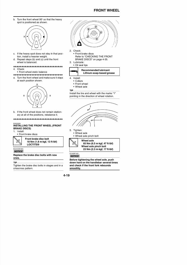
8/21/2019 Fz8 - Service Manual
http://slidepdf.com/reader/full/fz8-service-manual 186/609
wheel is balanced.
4. Check:• Front wheel static balance
a. Turn the front wheel and make sure it stays
at each position shown.
b. If the front wheel does not remain station-ary at all of the positions, rebalance it.
EAS22000
INSTALLING THE FRONT WHEEL (FRONTBRAKE DISCS)1 Install:
3. Lubricate:• Oil seal lips
4. Install:• Collars• Front wheel• Wheel axle
TIP
Install the tire and wheel with the marks “1”pointing in the direction of wheel rotation.
5. Tighten:
Recommended lubricantLithium-soap-based grease
FRONT WHEEL
TIP
Check that wheel axle end “a” is flush withfront folk surface “b” and then tighten the wheelaxle pinch bolt. If end “a” is not flush with sur-face “b”, align the ends manually or with a
plastic hammer.
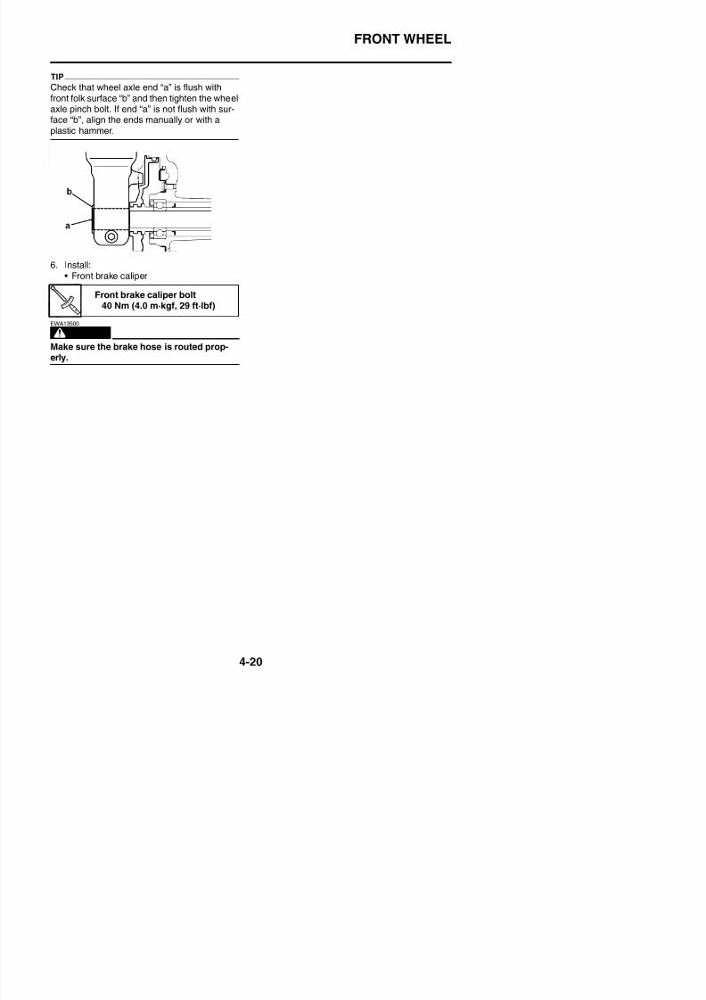
8/21/2019 Fz8 - Service Manual
http://slidepdf.com/reader/full/fz8-service-manual 187/609
6. Install:• Front brake caliper
WARNING
EWA13500
Make sure the brake hose is routed prop-erly.
Front brake caliper bolt40 Nm (4.0 m·kgf, 29 ft·lbf)
REAR WHEEL
EAS22020
REAR WHEEL
Removing the rear wheel
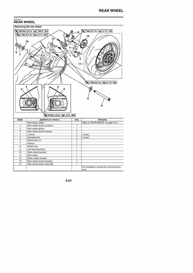
8/21/2019 Fz8 - Service Manual
http://slidepdf.com/reader/full/fz8-service-manual 188/609
Order Job/Parts to remove Q’ty Remarks
Rear brake caliper Refer to “REAR BRAKE” on page 4-43.
1 Rear wheel sensor protector 1
2 Rear wheel sensor 1
3 Rear wheel sensor bracket 1
4 Locknut 2 Loosen.
REAR WHEEL
Removing the brake disc and rear wheel sprocket
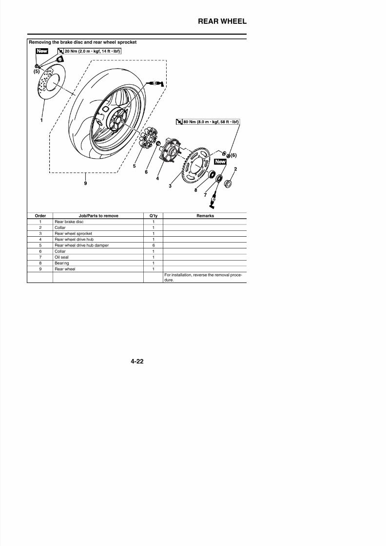
8/21/2019 Fz8 - Service Manual
http://slidepdf.com/reader/full/fz8-service-manual 189/609
Order Job/Parts to remove Q’ty Remarks
1 Rear brake disc 1
2 Collar 1
3 Rear wheel sprocket 1
4 Rear wheel drive hub 1
5 Rear wheel drive hub damper 6
6 Collar 1
7 Oil seal 1
8 Bearing 1
9 Rear wheel 1
REAR WHEEL
Disassembling the rear wheel
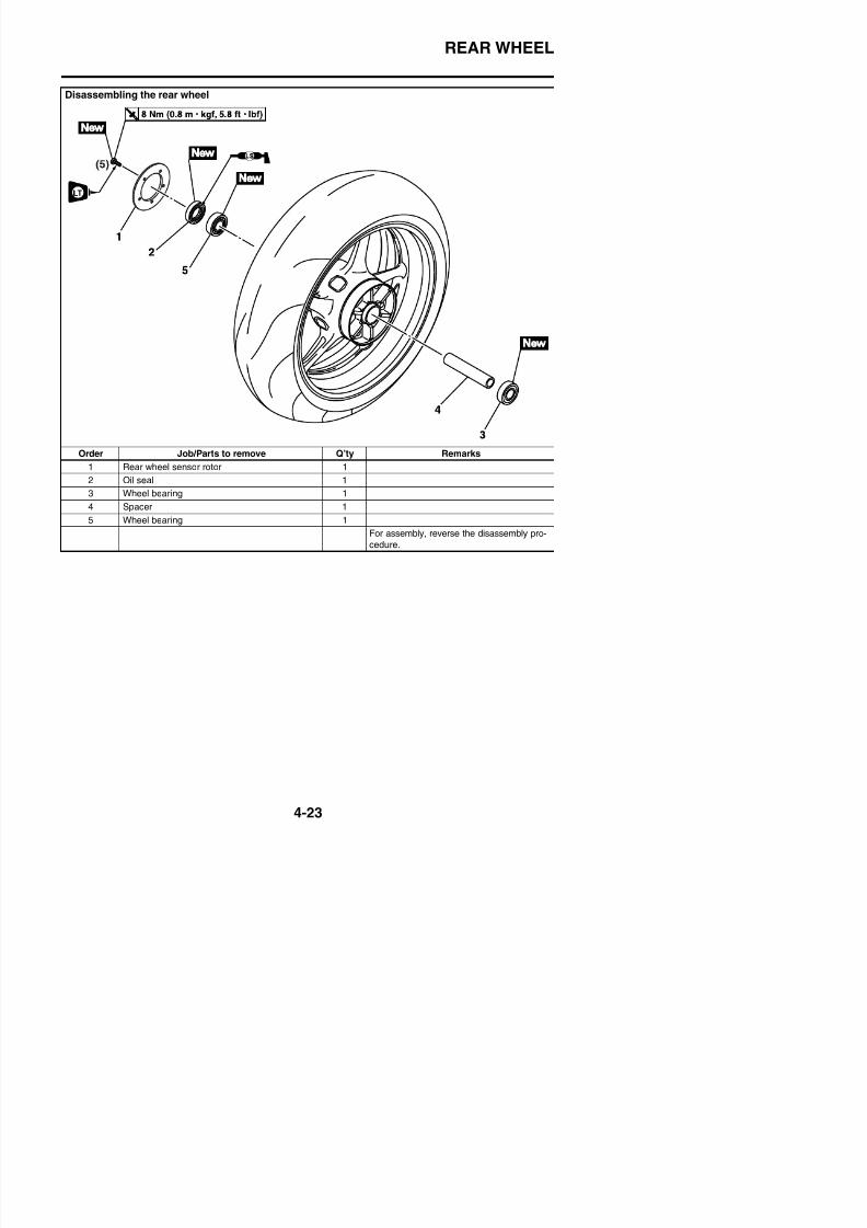
8/21/2019 Fz8 - Service Manual
http://slidepdf.com/reader/full/fz8-service-manual 190/609
Order Job/Parts to remove Q’ty Remarks
1 Rear wheel sensor rotor 1
2 Oil seal 1
3 Wheel bearing 1
4 Spacer 1
5 Wheel bearing 1
For assembly, reverse the disassembly pro-
cedure.
REAR WHEEL
EAS22040
REMOVING THE REAR WHEEL1. Stand the vehicle on a level surface.
WARNING
EWA13120
Securely support the vehicle so that thereis no danger of it falling over.
TIP
Place the vehicle on a suitable stand so thatthe rear wheel is elevated.
2. Remove:
• Rear brake caliper “1”
• Rear wheel sensorTIP
Do not depress the brake pedal when remov
EAS22091
CHECKING THE REAR WHEEL
1. Check:• Wheel axle• Wheel bearings
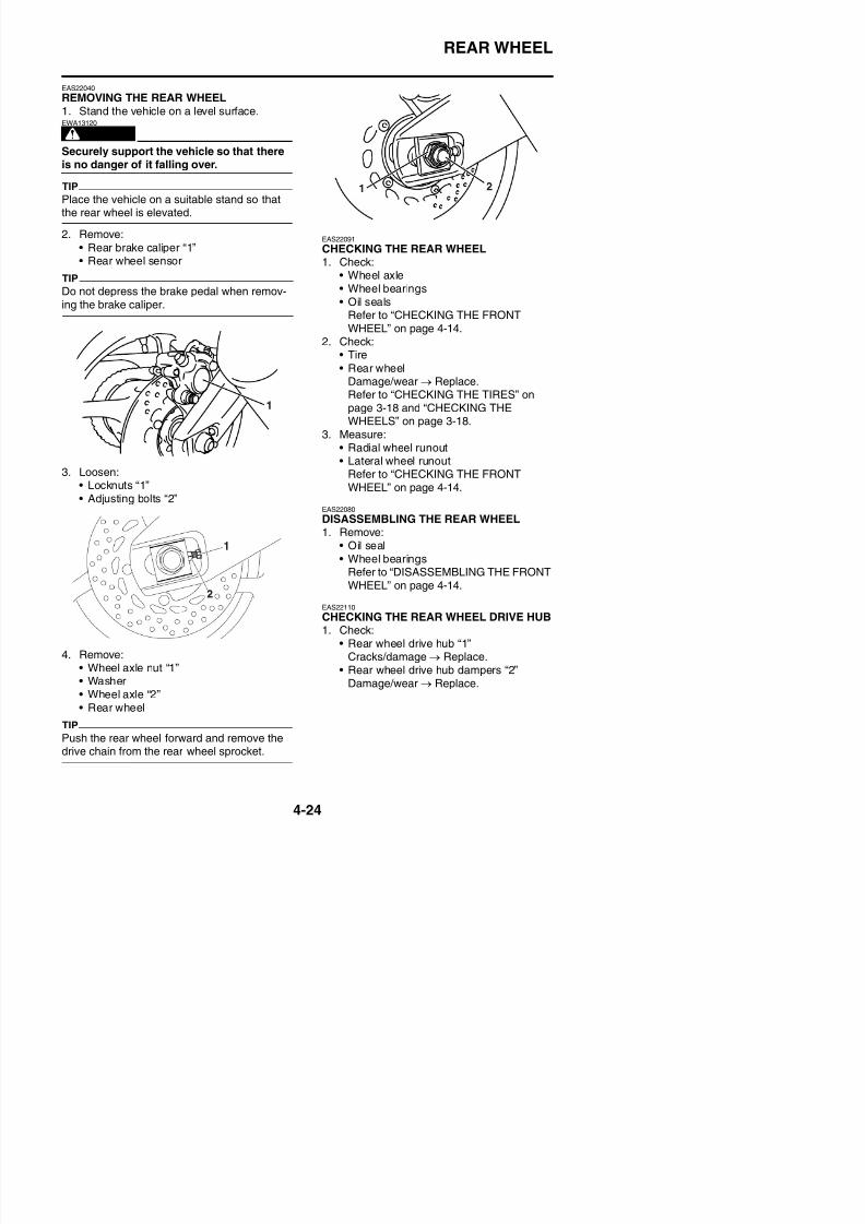
8/21/2019 Fz8 - Service Manual
http://slidepdf.com/reader/full/fz8-service-manual 191/609
Do not depress the brake pedal when remov-ing the brake caliper.
3. Loosen:• Locknuts “1”• Adjusting bolts “2”
• Wheel bearings• Oil seals
Refer to “CHECKING THE FRONTWHEEL” on page 4-14.
2. Check:• Tire
• Rear wheelDamage/wear → Replace.Refer to “CHECKING THE TIRES” onpage 3-18 and “CHECKING THEWHEELS” on page 3-18.
3. Measure:• Radial wheel runout• Lateral wheel runout
Refer to “CHECKING THE FRONTWHEEL” on page 4-14.
EAS22080
DISASSEMBLING THE REAR WHEEL1. Remove:
• Oil seal• Wheel bearings
Refer to “DISASSEMBLING THE FRONT
WHEEL” on page 4-14.
EAS22110
REAR WHEEL
EAS14B1003
CHECKING AND REPLACING THE REARWHEEL SPROCKET1. Check:
• Rear wheel sprocketMore than 1/4 tooth “a” wear → Replacethe drive chain sprockets as a set
EAS22140
ASSEMBLING THE REAR WHEEL1. Install:
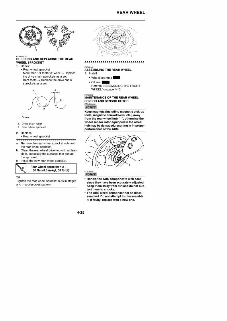
8/21/2019 Fz8 - Service Manual
http://slidepdf.com/reader/full/fz8-service-manual 192/609
the drive chain sprockets as a set.Bent teeth → Replace the drive chainsprockets as a set.
2. Replace:• Rear wheel sprocket
a. Remove the rear wheel sprocket nuts andthe rear wheel sprocket.
b. Clean the rear wheel drive hub with a clean
cloth, especially the surfaces that contactthe sprocket.
• Wheel bearings
• Oil seal
Refer to “ASSEMBLING THE FRONTWHEEL” on page 4-15.
EAS22200
MAINTENANCE OF THE REAR WHEELSENSOR AND SENSOR ROTORECA4B56008
Keep magnets (including magnetic pick-uptools, magnetic screwdrivers, etc.) awayfrom the rear wheel hub “1”, otherwise thewheel sensor rotor equipped in the wheel
hub may be damaged, resulting in improperperformance of the ABS.
b. Correct
1. Drive chain roller2. Rear wheel sprocket
New
New
REAR WHEEL
Removing the rear wheel sensor1. Disconnect:
• Rear wheel sensor coupler “1”
2. Remove:• Clamps “1”
Checking the rear wheel sensor and sensorrotor1. Check:
• Rear wheel sensorCracks/bends/distortion → Replace.
Iron powder/dust → Clean.2. Check:
• Rear wheel sensor rotorCracks/damage → Replace.
3. Measure:• Wheel sensor rotor deflection
Out of specification → Clean the installa-tion surface of the wheel sensor rotor and
correct the wheel sensor rotor deflection,or replace the wheel sensor rotor.Refer to “MAINTENANCE OF THE

8/21/2019 Fz8 - Service Manual
http://slidepdf.com/reader/full/fz8-service-manual 193/609
• Brake hose holders “2”
3. Remove:• Rear wheel sensor• Rear wheel
Refer to “REMOVING THE REARWHEEL” on page 4-24.
ECA1CW1402
• Be sure not to contact the sensor elec-trode to any metal part when removingthe rear wheel sensor from the sensor
housing.• Do not operate the brake pedal when
FRONT WHEEL SENSOR AND SEN-SOR ROTOR” on page 4-15.
Installing the rear wheel sensor1. Install:
• Rear wheel sensor rotor “1”
ECA4B56012
Replace the wheel sensor rotor bolts withnew ones.
Wheel sensor rotor deflectionlimit
0.15 mm (0.0059 in)
Wheel sensor rotor bolt8 Nm (0.8 m·kgf, 5.8 ft·lbf)LOCTITE®
REAR WHEEL
ECA14470
Make sure there are no foreign materials inthe wheel hub. Foreign materials causedamage to the inner sensor rotor and wheel
sensor.3. Measure:
TIP
Measure the distance “a” only if the wheelbearings, wheel sensor rotor, or both werereplaced.
• Distance “a”
(between the wheel sensor rotor “1” andwheel sensor housing “2”)Out of specification → Reinstall the bear-
ECA14500
To route the rear wheel sensor lead, refer to“CABLE ROUTING” on page 2-43.
5. Install:
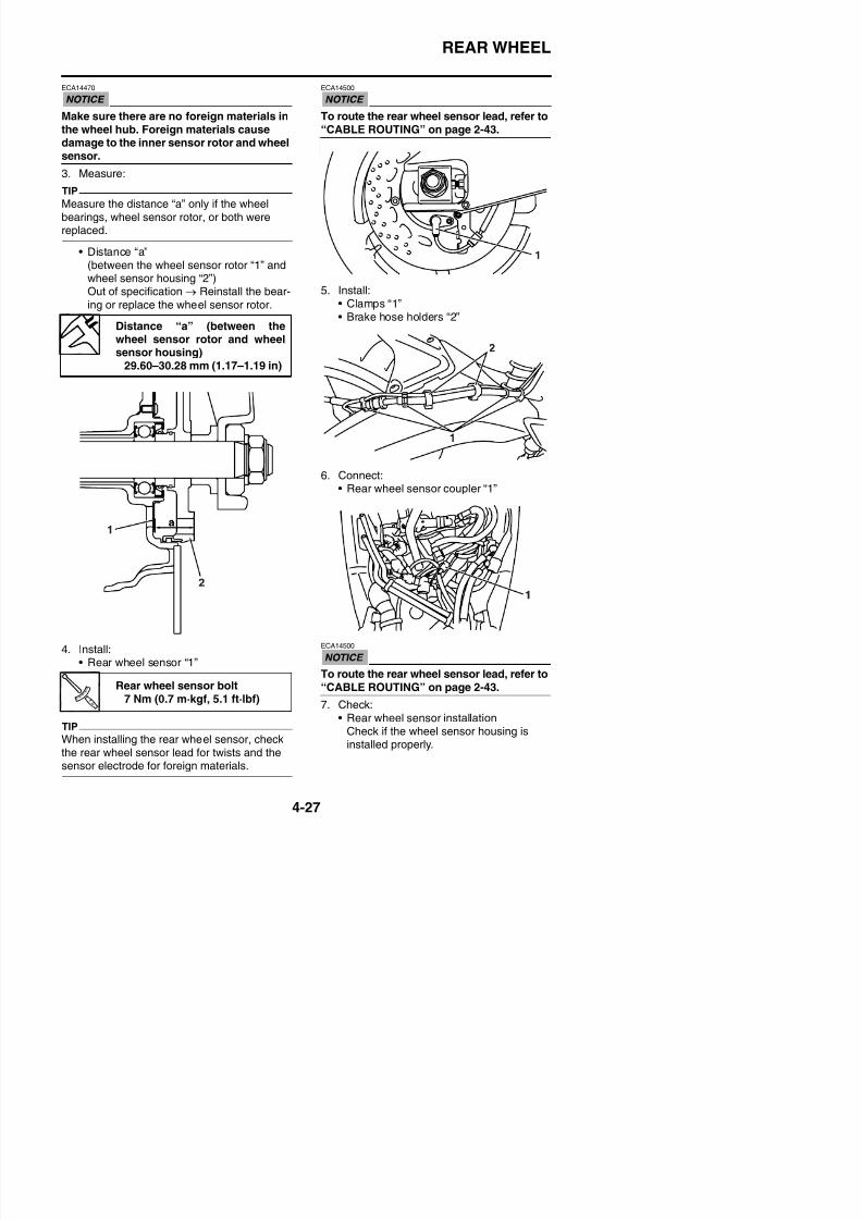
8/21/2019 Fz8 - Service Manual
http://slidepdf.com/reader/full/fz8-service-manual 194/609
Out of specification → Reinstall the bear
ing or replace the wheel sensor rotor.
5. Install:• Clamps “1”• Brake hose holders “2”
6. Connect:• Rear wheel sensor coupler “1”
Distance “a” (between thewheel sensor rotor and wheelsensor housing)
29.60–30.28 mm (1.17–1.19 in)
REAR WHEEL
EAS22150
ADJUSTING THE REAR WHEEL STATICBALANCE
TIP
• After replacing the tire, wheel or both, the
rear wheel static balance should be adjusted.• Adjust the rear wheel static balance with the
brake disc and rear wheel drive hub installed.
1. Adjust:• Rear wheel static balance
Refer to “ADJUSTING THE FRONTWHEEL STATIC BALANCE” on page 4-18.
EAS22160
INSTALLING THE REAR WHEEL (REAR
3. Lubricate:• Oil seal lips
4. Install:• Collar
• Rear wheel sensor housing• Brake caliper bracket• Rear wheel• Adjusting blocks• Wheel axle• Washer
• Wheel axle nut
TIP
D t i t ll th b k li
Recommended lubricantLithium-soap-based grease
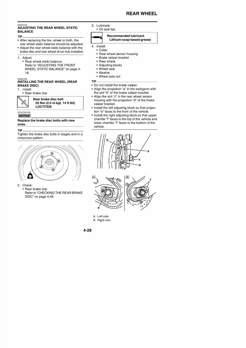
8/21/2019 Fz8 - Service Manual
http://slidepdf.com/reader/full/fz8-service-manual 195/609
BRAKE DISC)1. Install:
• Rear brake disc
ECA1CW1401
Replace the brake disc bolts with new
ones.
TIP
Tighten the brake disc bolts in stages and in acrisscross pattern.
• Do not install the brake caliper.• Align the projection “a” in the swingarm with
the slot “b” of the brake caliper bracket.• Align the slot “c” in the rear wheel sensor
housing with the projection “d” of the brake
caliper bracket.• Install the left adjusting block so that projec-tion “e” faces to the front of the vehicle.
• Install the right adjusting block so that upperchamfer “f” faces to the top of the vehicle andlower chamfer “f” faces to the bottom of thevehicle.
Rear brake disc bolt20 Nm (2.0 m·kgf, 14 ft·lbf)
LOCTITE®
REAR WHEEL
5. Install:• Rear brake caliper• Rear brake caliper retaining bolts
6. Adjust:• Drive chain slack
Refer to “ADJUSTING THE DRIVECHAIN SLACK” on page 3-19.
7. Tighten:• Wheel axle nut• Rear brake caliper retaining bolts
Drive chain slack 20.0–30.0 mm (0.79–1.18 in)
Wheel axle nut150 Nm (15 m·kgf, 108 ft·lbf)
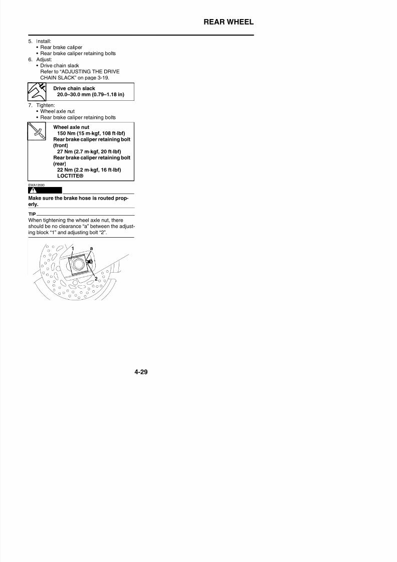
8/21/2019 Fz8 - Service Manual
http://slidepdf.com/reader/full/fz8-service-manual 196/609
WARNING
EWA13500
Make sure the brake hose is routed prop-erly.
TIP
When tightening the wheel axle nut, thereshould be no clearance “a” between the adjust-
ing block “1” and adjusting bolt “2”.
Rear brake caliper retaining bolt(front)
27 Nm (2.7 m·kgf, 20 ft·lbf)Rear brake caliper retaining bolt(rear)
22 Nm (2.2 m·kgf, 16 ft·lbf)LOCTITE®
FRONT BRAKE
EAS22210
FRONT BRAKE
Removing the front brake pads
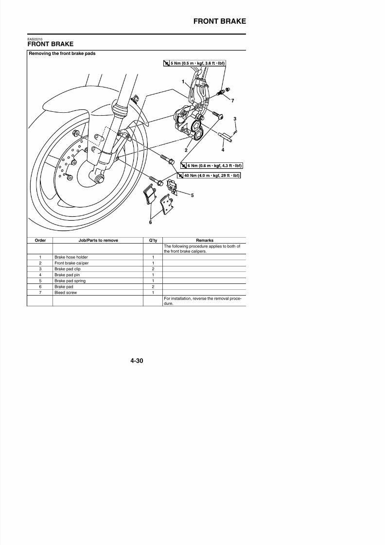
8/21/2019 Fz8 - Service Manual
http://slidepdf.com/reader/full/fz8-service-manual 197/609
Order Job/Parts to remove Q’ty Remarks
The following procedure applies to both of
the front brake calipers.
1 Brake hose holder 1
2 Front brake caliper 1
3 Brake pad clip 2
FRONT BRAKE
Removing the front brake master cylinder
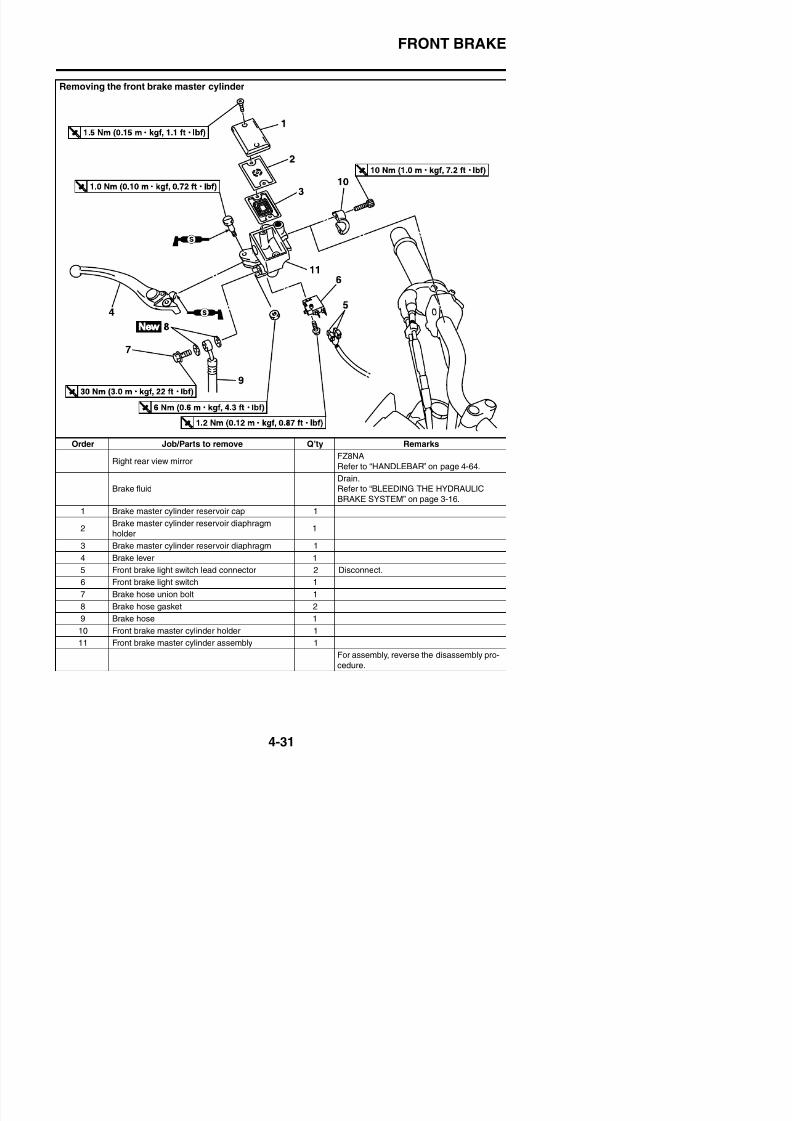
8/21/2019 Fz8 - Service Manual
http://slidepdf.com/reader/full/fz8-service-manual 198/609
Order Job/Parts to remove Q’ty Remarks
Right rear view mirrorFZ8NA
Refer to “HANDLEBAR” on page 4-64.
Brake fluid
Drain.
Refer to “BLEEDING THE HYDRAULIC
BRAKE SYSTEM” on page 3-16.
1 Brake master cylinder reservoir cap 1
2Brake master cylinder reservoir diaphragm
holder
1
3 Brake master cylinder reservoir diaphragm 1
4 B k l 1
FRONT BRAKE
Disassembling the front brake master cylinder
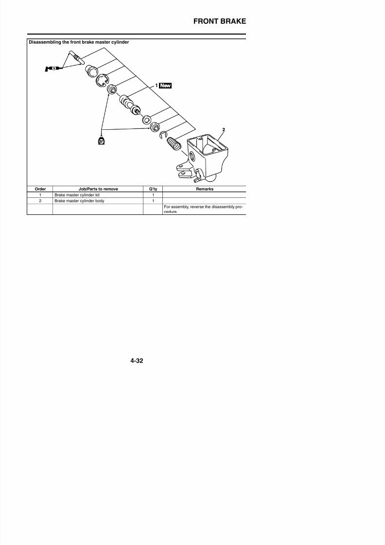
8/21/2019 Fz8 - Service Manual
http://slidepdf.com/reader/full/fz8-service-manual 199/609
Order Job/Parts to remove Q’ty Remarks
1 Brake master cylinder kit 1
2 Brake master cylinder body 1
For assembly, reverse the disassembly pro-
cedure.
FRONT BRAKE
Removing the front brake calipers
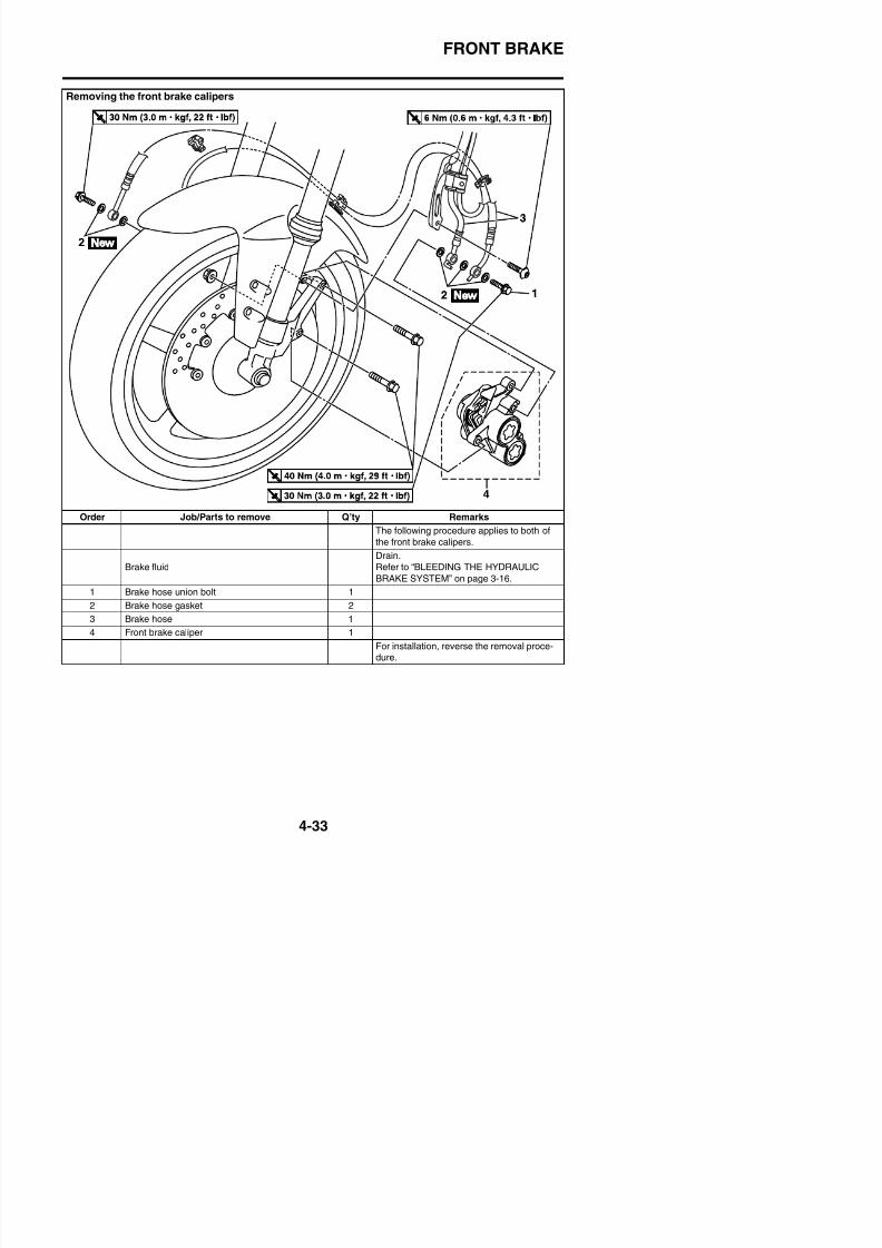
8/21/2019 Fz8 - Service Manual
http://slidepdf.com/reader/full/fz8-service-manual 200/609
Order Job/Parts to remove Q’ty Remarks
The following procedure applies to both of
the front brake calipers.
Brake fluid
Drain.
Refer to “BLEEDING THE HYDRAULIC
BRAKE SYSTEM” on page 3-16.
1 Brake hose union bolt 1
2 Brake hose gasket 2
3 Brake hose 1
FRONT BRAKE
Disassembling the front brake calipers
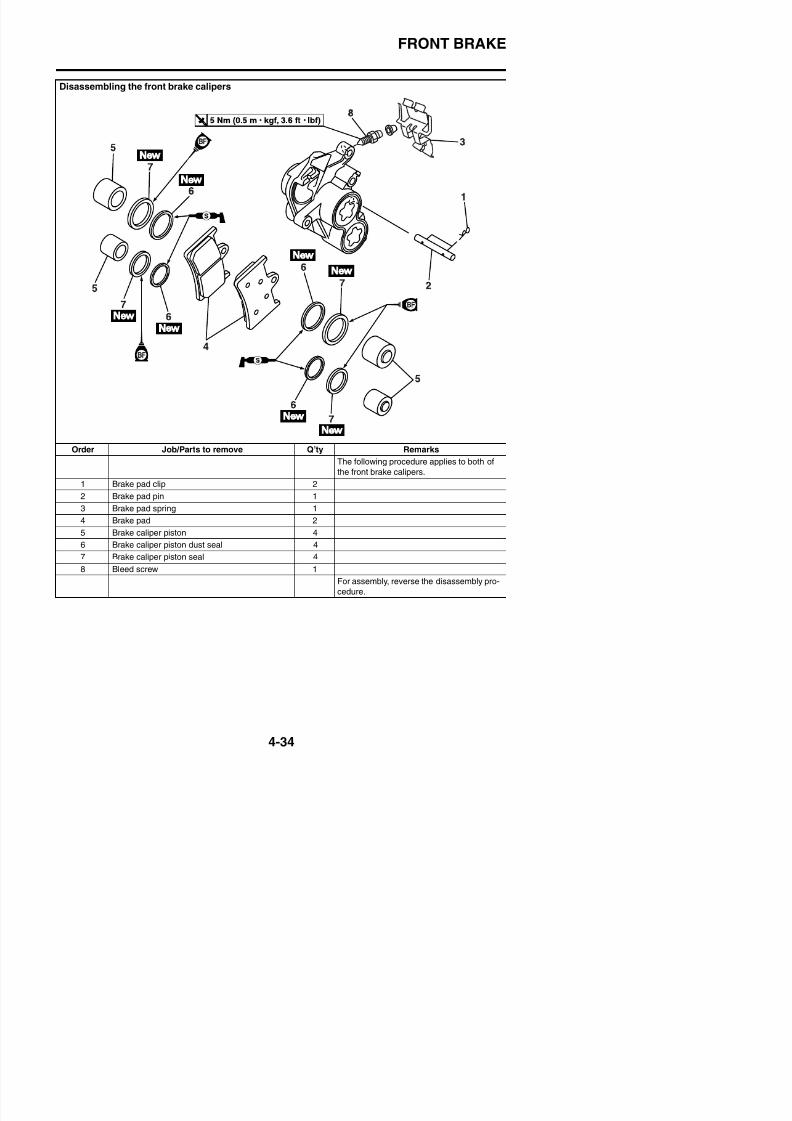
8/21/2019 Fz8 - Service Manual
http://slidepdf.com/reader/full/fz8-service-manual 201/609
Order Job/Parts to remove Q’ty Remarks
The following procedure applies to both of
the front brake calipers.
1 Brake pad clip 2
2 Brake pad pin 1
3 Brake pad spring 1
4 Brake pad 2
5 Brake caliper piston 46 Brake caliper piston dust seal 4
7 Brake caliper piston seal 4
FRONT BRAKE
EAS22220
INTRODUCTION
WARNING
EWA14100
Disc brake components rarely require dis-assembly. Therefore, always follow thesepreventive measures:• Never disassemble brake components
unless absolutely necessary.• If any connection on the hydraulic brake
system is disconnected, the entire brakesystem must be disassembled, drained,cleaned, properly filled, and bled afterreassembly.
• Never use solvents on internal brakecomponents.
• Use only clean or new brake fluid forl i b k t
d. Hold the dial gauge at a right angle againstthe brake disc surface.
e. Measure the deflection 1.5 mm (0.06 in)below the edge of the brake disc.
4. Measure:• Brake disc thickness
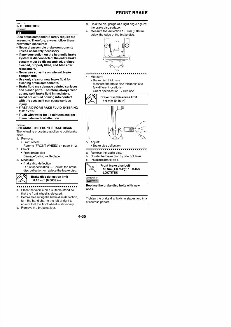
8/21/2019 Fz8 - Service Manual
http://slidepdf.com/reader/full/fz8-service-manual 202/609
cleaning brake components.• Brake fluid may damage painted surfaces
and plastic parts. Therefore, always cleanup any spilt brake fluid immediately.
• Avoid brake fluid coming into contact
with the eyes as it can cause seriousinjury.
• FIRST AID FOR BRAKE FLUID ENTERINGTHE EYES:
• Flush with water for 15 minutes and getimmediate medical attention.
EAS22240
CHECKING THE FRONT BRAKE DISCSThe following procedure applies to both brakediscs.1. Remove:
• Front wheelRefer to “FRONT WHEEL” on page 4-12.
2. Check:• Front brake disc
Damage/galling → Replace.3. Measure:
Measure the brake disc thickness at afew different locations.Out of specification → Replace.
5. Adjust:• Brake disc deflection
a. Remove the brake disc.
b. Rotate the brake disc by one bolt hole.c. Install the brake disc.
Brake disc thickness limit
4.0 mm (0.16 in)
FRONT BRAKE
d. Measure the brake disc deflection.e. If out of specification, repeat the adjust-
ment steps until the brake disc deflection is
within specification.f. If the brake disc deflection cannot bebrought within specification, replace thebrake disc.
3. Measure:• Brake pad wear limit “a”
Out of specification → Replace the brakepads as a set.
Brake pad lining thickness
(inner)4.5 mm (0.18 in)
Limit0.5 mm (0.02 in)
Brake pad lining thickness(outer)
4.5 mm (0.18 in)Limit
0.5 mm (0.02 in)
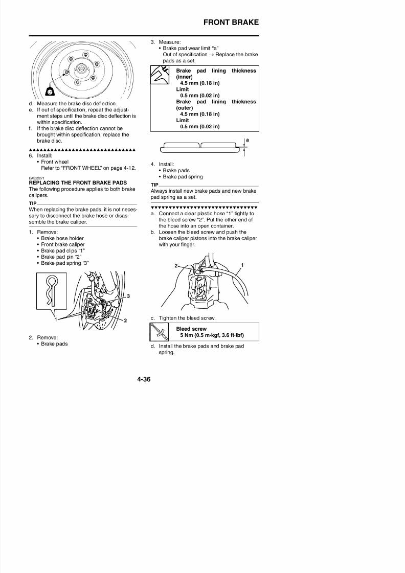
8/21/2019 Fz8 - Service Manual
http://slidepdf.com/reader/full/fz8-service-manual 203/609
6. Install:• Front wheel
Refer to “FRONT WHEEL” on page 4-12.
EAS22271
REPLACING THE FRONT BRAKE PADSThe following procedure applies to both brakecalipers.
TIP
When replacing the brake pads, it is not neces-sary to disconnect the brake hose or disas-
semble the brake caliper.1. Remove:
• Brake hose holder• Front brake caliper• Brake pad clips “1”• Brake pad pin “2”• Brake pad spring “3”
4. Install:• Brake pads
• Brake pad spring
TIP
Always install new brake pads and new brakepad spring as a set.
a. Connect a clear plastic hose “1” tightly tothe bleed screw “2”. Put the other end of
the hose into an open container.b. Loosen the bleed screw and push the
brake caliper pistons into the brake caliperwith your finger.
FRONT BRAKE
TIP
The arrow mark “a” on the brake pad springmust point in the direction of disc rotation.
5. Install:• Brake pad pin• Brake pad clips
F b k li
EAS22300
REMOVING THE FRONT BRAKE CALIPERSThe following procedure applies to both of thebrake calipers.
TIP
Before removing the brake caliper, drain thebrake fluid from the entire brake system.
1. Remove:
• Brake hose union bolt “1”• Brake hose gaskets “2”• Brake hose “3”
TIP
Put the end of the brake hose into a container
and pump out the brake fluid carefully.
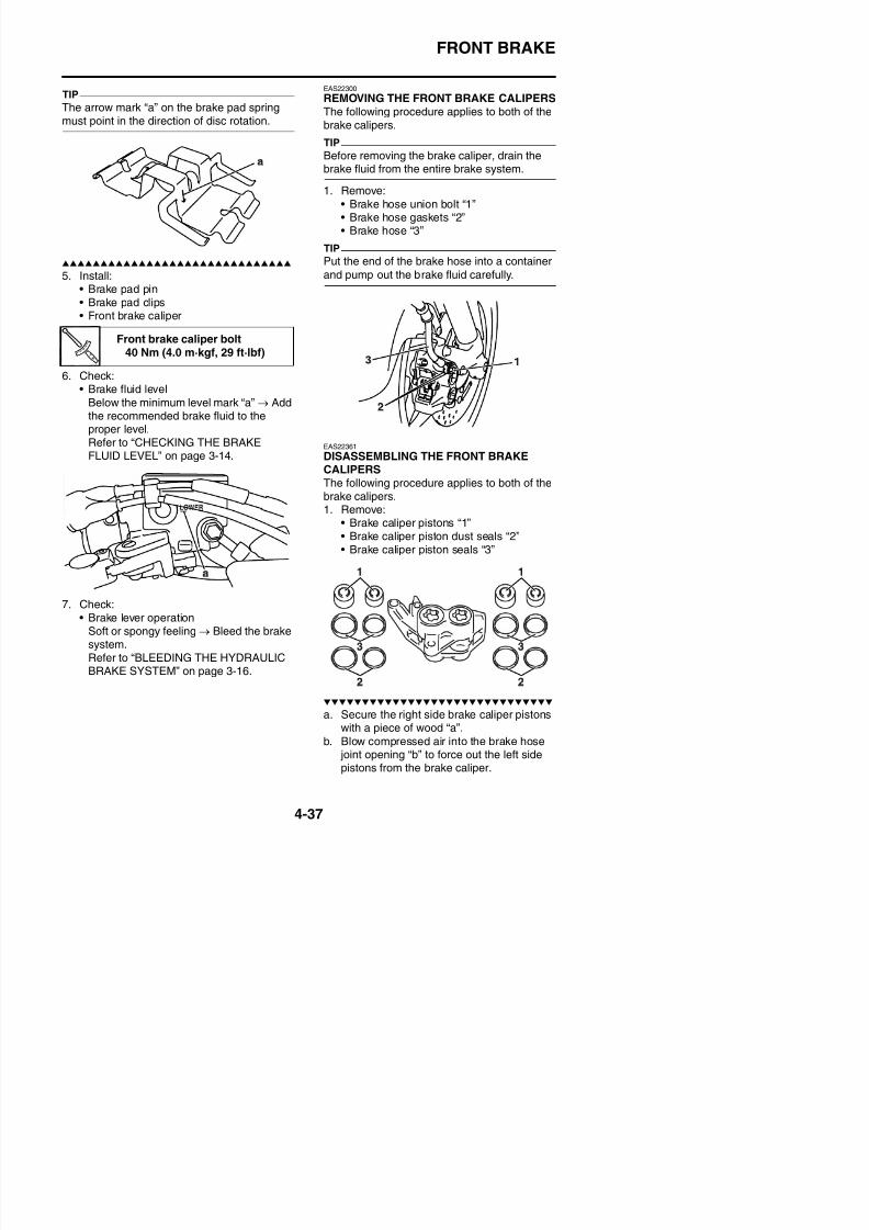
8/21/2019 Fz8 - Service Manual
http://slidepdf.com/reader/full/fz8-service-manual 204/609
• Front brake caliper
6. Check:• Brake fluid level
Below the minimum level mark “a” → Addthe recommended brake fluid to theproper level.Refer to “CHECKING THE BRAKEFLUID LEVEL” on page 3-14.
7. Check:
EAS22361
DISASSEMBLING THE FRONT BRAKECALIPERS
The following procedure applies to both of thebrake calipers.1. Remove:
• Brake caliper pistons “1”• Brake caliper piston dust seals “2”• Brake caliper piston seals “3”
Front brake caliper bolt40 Nm (4.0 m·kgf, 29 ft·lbf)
FRONT BRAKE
WARNING
EWA39P1401
• Never try to pry out the brake caliper pis-tons.
• Do not loosen the bolts “4”.
c. Remove the brake caliper piston dust sealsand brake caliper piston seals
WARNING
EWA13611
Whenever a brake caliper is disassembled,replace the brake caliper piston dust sealsand brake caliper piston seals.
EAS22411
ASSEMBLING THE FRONT BRAKE CALI
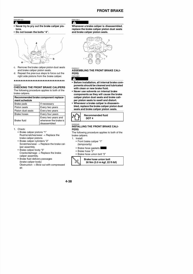
8/21/2019 Fz8 - Service Manual
http://slidepdf.com/reader/full/fz8-service-manual 205/609
and brake caliper piston seals.d. Repeat the previous steps to force out the
right side pistons from the brake caliper.
EAS22391
CHECKING THE FRONT BRAKE CALIPERSThe following procedure applies to both of thebrake calipers.
1. Check:
• Brake caliper pistons “1”Rust/scratches/wear → Replace the
ASSEMBLING THE FRONT BRAKE CALI-PERS
WARNING
EWA13621
• Before installation, all internal brake com-ponents should be cleaned and lubricatedwith clean or new brake fluid.
• Never use solvents on internal brakecomponents as they will cause the brakecaliper piston dust seals and brake cali-
per piston seals to swell and distort.• Whenever a brake caliper is disassem-
bled, replace the brake caliper piston dustseals and brake caliper piston seals.
EAS22440
INSTALLING THE FRONT BRAKE CALI-PERS
The following procedure applies to both of thebrake calipers
Recommended brake component replace-ment schedule
Brake pads If necessary
Piston seals Every two yearsPiston dust seals Every two years
Brake hoses Every four years
Brake fluidEvery two years andwhenever the brake isdisassembled
Recommended fluidDOT 4
FRONT BRAKE
WARNING
EWA13530
Proper brake hose routing is essential toinsure safe vehicle operation. Refer to“CABLE ROUTING” on page 2-43.
ECA14170
When installing the brake hose onto thebrake caliper “1”, make sure the brake pipe“a” touches the projection “b” on the brakecaliper.
WARNING
EWA13090
• Use only the designated brake fluid.Other brake fluids may cause the rubberseals to deteriorate, causing leakage and
poor brake performance.• Refill with the same type of brake fluidthat is already in the system. Mixing brake
fluids may result in a harmful chemicalreaction, leading to poor brake perfor-mance.
• When refilling, be careful that water doesnot enter the brake fluid reservoir. Water
will significantly lower the boiling point ofthe brake fluid and could cause vaporlock.
ECA13540
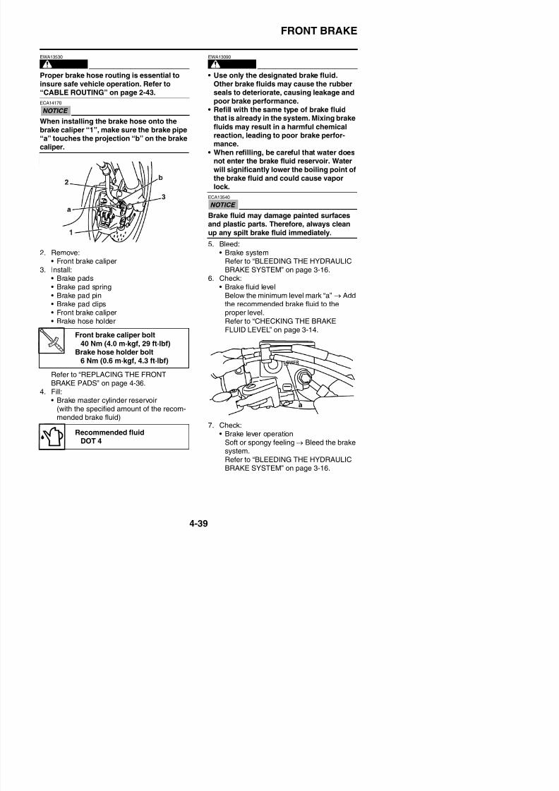
8/21/2019 Fz8 - Service Manual
http://slidepdf.com/reader/full/fz8-service-manual 206/609
2. Remove:• Front brake caliper
3. Install:• Brake pads• Brake pad spring• Brake pad pin• Brake pad clips
• Front brake caliper• Brake hose holder
Refer to “REPLACING THE FRONTBRAKE PADS” on page 4-36.
4 Fill:
Brake fluid may damage painted surfacesand plastic parts. Therefore, always cleanup any spilt brake fluid immediately.
5. Bleed:• Brake system
Refer to “BLEEDING THE HYDRAULICBRAKE SYSTEM” on page 3-16.
6. Check:• Brake fluid level
Below the minimum level mark “a” → Addthe recommended brake fluid to the
proper level.Refer to “CHECKING THE BRAKEFLUID LEVEL” on page 3-14.
Front brake caliper bolt40 Nm (4.0 m·kgf, 29 ft·lbf)
Brake hose holder bolt6 Nm (0.6 m·kgf, 4.3 ft·lbf)
FRONT BRAKE
EAS22490
REMOVING THE FRONT BRAKE MASTERCYLINDER
TIP
Before removing the front brake master cylin-der, drain the brake fluid from the entire brakesystem.
1. Disconnect:
• Brake light switch connectors(from the front brake light switch)
2. Remove:• Brake hose union bolt “1”• Brake hose gaskets “2”
• Brake hose “3”
TIP
To collect any remaining brake fluid, place acontainer under the master cylinder and the
4. Check:• Brake hoses “1”
Cracks/damage/wear → Replace.
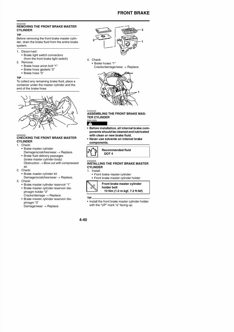
8/21/2019 Fz8 - Service Manual
http://slidepdf.com/reader/full/fz8-service-manual 207/609
container under the master cylinder and theend of the brake hose.
EAS22500
CHECKING THE FRONT BRAKE MASTERCYLINDER1. Check:
• Brake master cylinderDamage/scratches/wear → Replace.
• Brake fluid delivery passages
(brake master cylinder body)Obstruction → Blow out with compressed
EAS22520
ASSEMBLING THE FRONT BRAKE MAS-TER CYLINDER
WARNING
EWA13520
• Before installation, all internal brake com-ponents should be cleaned and lubricatedwith clean or new brake fluid.
• Never use solvents on internal brakecomponents.
EAS22530
INSTALLING THE FRONT BRAKE MASTER
Recommended fluidDOT 4
FRONT BRAKE
• Align the end of the front brake master cylin-der holder with the punch mark “b” on thehandlebar.
• First, tighten the upper bolt, then the lowerbolt.
• There should be more than 11 mm (0.43 in)for clearance between the right handlebarswitch and the front brake master cylinderholder. Also, the punch mark should be seen.
3. Fill:• Brake master cylinder reservoir
(with the specified amount of the recom-
mended brake fluid)
Recommended fluidDOT 4
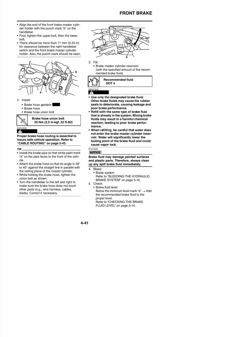
8/21/2019 Fz8 - Service Manual
http://slidepdf.com/reader/full/fz8-service-manual 208/609
2. Install:
• Brake hose gaskets
• Brake hose• Brake hose union bolt
WARNING
EWA13530
Proper brake hose routing is essential toinsure safe vehicle operation. Refer to“CABLE ROUTING” on page 2-43.
TIP
• Install the brake pipe so that white paint mark“a” on the pipe faces to the front of the vehi-cle.
• Attach the brake hose so that its angle is 30° to 40° against the straight line in parallel with
WARNING
EWA13540
• Use only the designated brake fluid.Other brake fluids may cause the rubberseals to deteriorate, causing leakage andpoor brake performance.
• Refill with the same type of brake fluidthat is already in the system. Mixing brakefluids may result in a harmful chemicalreaction, leading to poor brake perfor-mance.
• When refilling, be careful that water does
not enter the brake master cylinder reser-voir. Water will significantly lower theboiling point of the brake fluid and couldcause vapor lock.
ECA13540
Brake fluid may damage painted surfaces
and plastic parts. Therefore, always cleanup any spilt brake fluid immediately.
Brake hose union bolt30 Nm (3.0 m·kgf, 22 ft·lbf)
New
FRONT BRAKE
6. Check:• Brake lever operation
Soft or spongy feeling → Bleed the brake
system.Refer to “BLEEDING THE HYDRAULICBRAKE SYSTEM” on page 3-16.
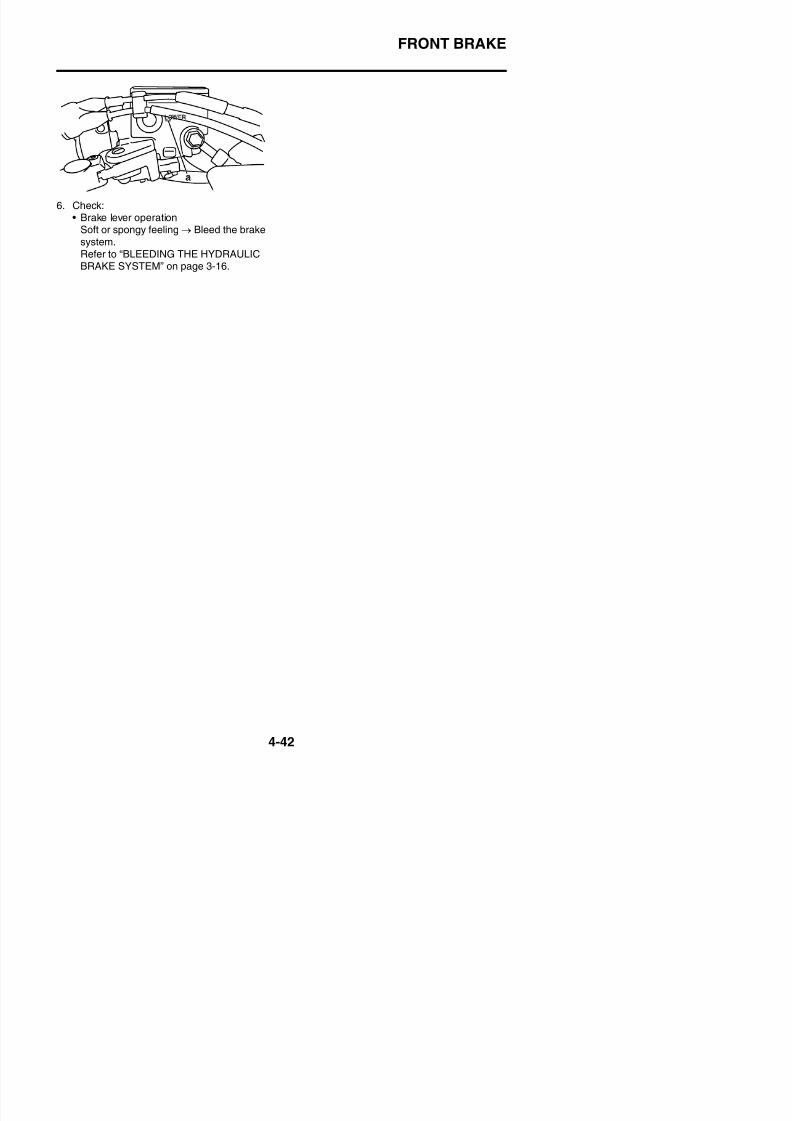
8/21/2019 Fz8 - Service Manual
http://slidepdf.com/reader/full/fz8-service-manual 209/609
REAR BRAKE
EAS22550
REAR BRAKE
Removing the rear brake pads
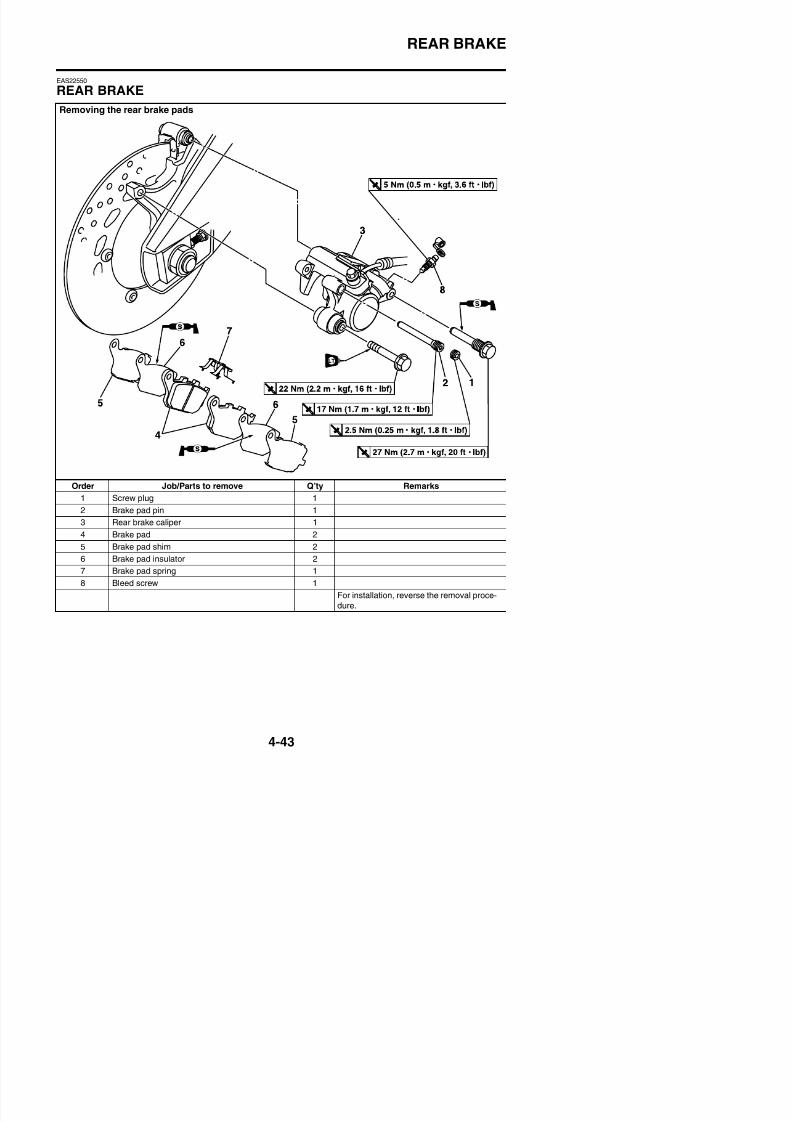
8/21/2019 Fz8 - Service Manual
http://slidepdf.com/reader/full/fz8-service-manual 210/609
Order Job/Parts to remove Q’ty Remarks
1 Screw plug 1
2 Brake pad pin 1
3 Rear brake caliper 1
4 Brake pad 25 Brake pad shim 2
REAR BRAKE
Removing the rear brake master cylinder
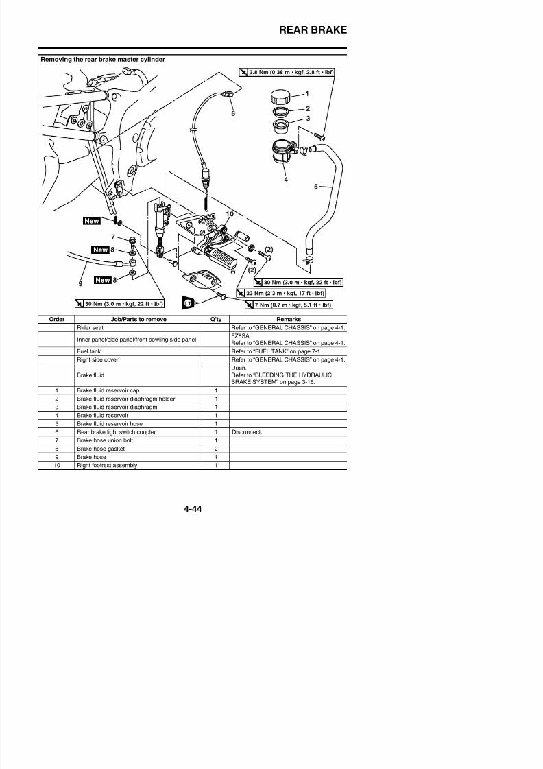
8/21/2019 Fz8 - Service Manual
http://slidepdf.com/reader/full/fz8-service-manual 211/609
Order Job/Parts to remove Q’ty Remarks
Rider seat Refer to “GENERAL CHASSIS” on page 4-1.
Inner panel/side panel/front cowling side panelFZ8SA
Refer to “GENERAL CHASSIS” on page 4-1.
Fuel tank Refer to “FUEL TANK” on page 7-1.
Right side cover Refer to “GENERAL CHASSIS” on page 4-1.
Brake fluidDrain.Refer to “BLEEDING THE HYDRAULICBRAKE SYSTEM” on page 3 16
REAR BRAKE
Removing the rear brake master cylinder
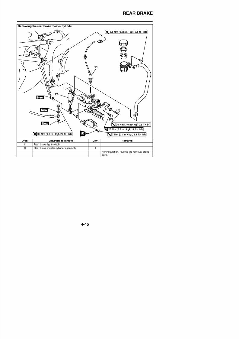
8/21/2019 Fz8 - Service Manual
http://slidepdf.com/reader/full/fz8-service-manual 212/609
Order Job/Parts to remove Q’ty Remarks
11 Rear brake light switch 1
12 Rear brake master cylinder assembly 1
For installation, reverse the removal proce-
dure.
REAR BRAKE
Disassembling the rear brake master cylinder
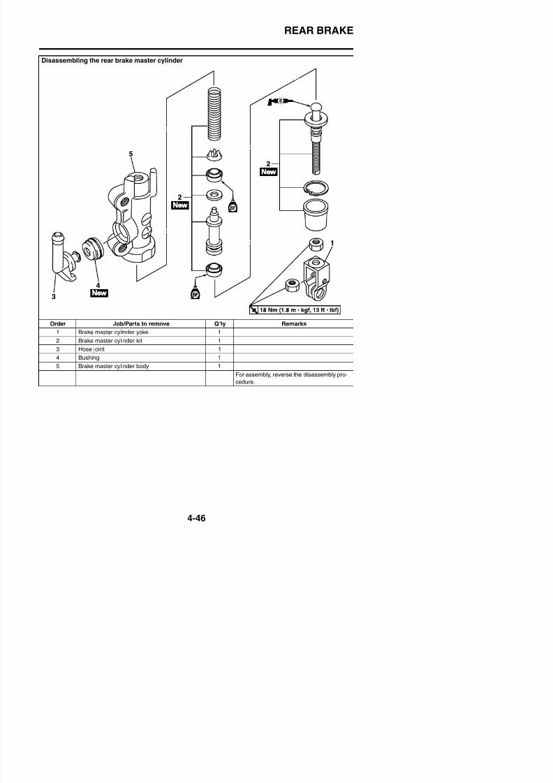
8/21/2019 Fz8 - Service Manual
http://slidepdf.com/reader/full/fz8-service-manual 213/609
Order Job/Parts to remove Q’ty Remarks
1 Brake master cylinder yoke 1
2 Brake master cylinder kit 1
3 Hose joint 1
4 Bushing 1
5 Brake master cylinder body 1
For assembly, reverse the disassembly pro-cedure.
REAR BRAKE
Removing the rear brake caliper
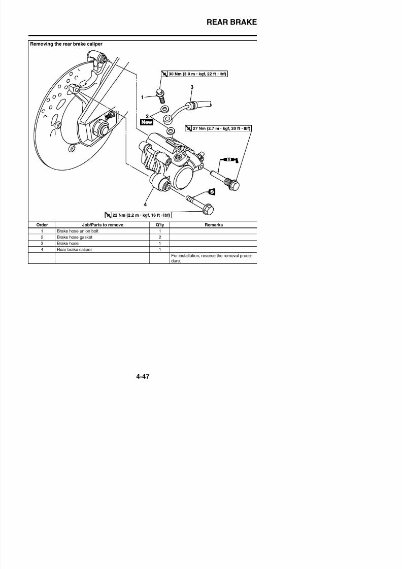
8/21/2019 Fz8 - Service Manual
http://slidepdf.com/reader/full/fz8-service-manual 214/609
Order Job/Parts to remove Q’ty Remarks1 Brake hose union bolt 1
2 Brake hose gasket 2
3 Brake hose 1
4 Rear brake caliper 1
For installation, reverse the removal proce-
dure.
REAR BRAKE
Disassembling the rear brake caliper
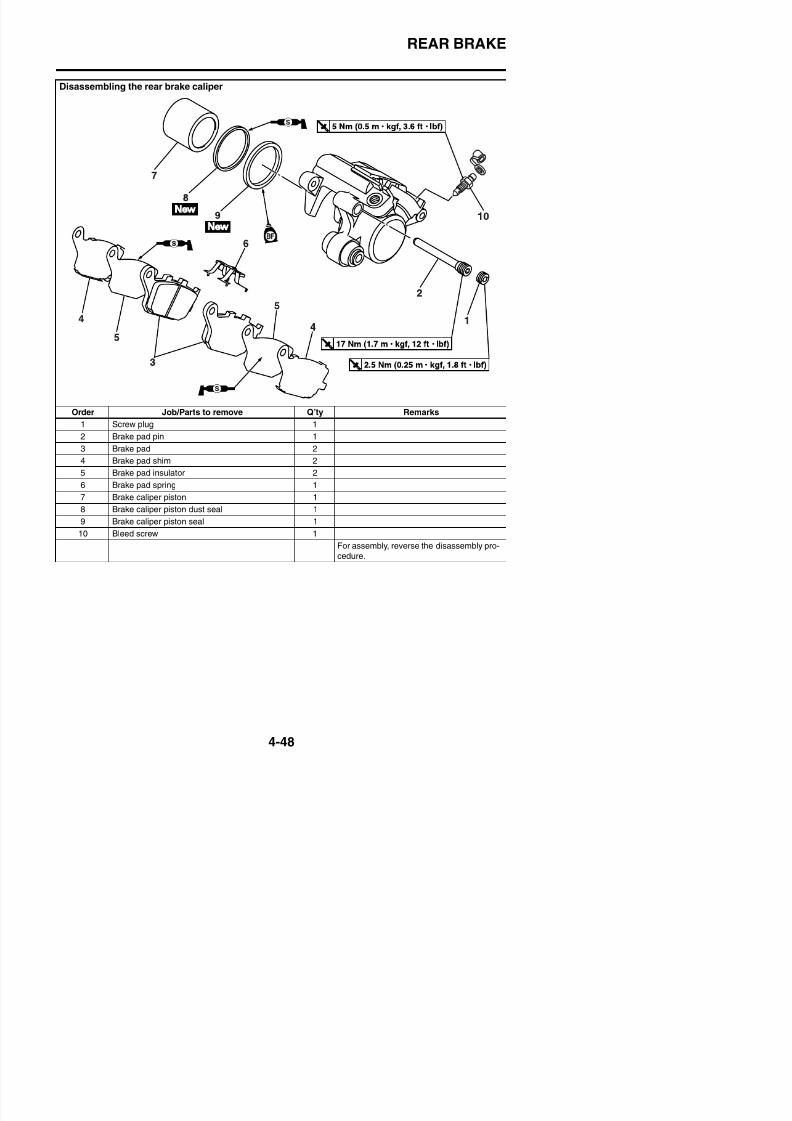
8/21/2019 Fz8 - Service Manual
http://slidepdf.com/reader/full/fz8-service-manual 215/609
Order Job/Parts to remove Q’ty Remarks
1 Screw plug 1
2 Brake pad pin 1
3 Brake pad 2
4 Brake pad shim 2
5 Brake pad insulator 2
6 Brake pad spring 1
7 Brake caliper piston 1
8 Brake caliper piston dust seal 1
9 Brake caliper piston seal 1
10 Bleed screw 1
For assembly, reverse the disassembly pro-
cedure
REAR BRAKE
EAS22561
INTRODUCTION
WARNING
EWA14101
Disc brake components rarely require dis-assembly. Therefore, always follow these
preventive measures:• Never disassemble brake components
unless absolutely necessary.• If any connection on the hydraulic brake
system is disconnected, the entire brakesystem must be disassembled, drained,cleaned, properly filled, and bled afterreassembly.
• Never use solvents on internal brakecomponents.
• Use only clean or new brake fluid forcleaning brake components.
• Brake fluid may damage painted surfaces
5. Adjust:• Brake disc deflection
Refer to “CHECKING THE FRONTBRAKE DISCS” on page 4-35.
6. Install:• Rear wheel
Refer to “REAR WHEEL” on page 4-21.
EAS22581
REPLACING THE REAR BRAKE PADS
TIP
Brake disc thickness limit4.5 mm (0.18 in)
Rear brake disc bolt20 Nm (2.0 m·kgf, 14 ft·lbf)LOCTITE®
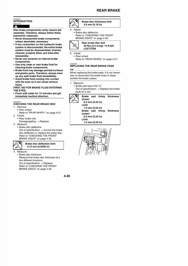
8/21/2019 Fz8 - Service Manual
http://slidepdf.com/reader/full/fz8-service-manual 216/609
y g pand plastic parts. Therefore, always cleanup any spilt brake fluid immediately.
• Avoid brake fluid coming into contact
with the eyes as it can cause seriousinjury.
FIRST AID FOR BRAKE FLUID ENTERINGTHE EYES:• Flush with water for 15 minutes and get
immediate medical attention.
EAS22570
CHECKING THE REAR BRAKE DISC1. Remove:• Rear wheel
Refer to “REAR WHEEL” on page 4-21.2. Check:
• Rear brake discDamage/galling → Replace.
3. Measure:
• Brake disc deflectionOut of specification → Correct the brake
When replacing the brake pads, it is not neces-sary to disconnect the brake hose or disas-semble the brake caliper.
1. Measure:• Brake pad wear limit “a”
Out of specification → Replace the brakepads as a set.
Brake pad lining thickness(inner)
6.0 mm (0.24 in)
Limit1.0 mm (0.04 in)
Brake pad lining thickness(outer)
6.0 mm (0.24 in)Limit
1.0 mm (0.04 in)
REAR BRAKE
2. Install:• Brake pad insulators• Brake pad shims
(onto the brake pads)• Brake pad spring
(into the rear brake caliper)• Brake pads
TIP
Always install new brake pads, brake pad insu-lators, brake pad shims, and brake pad springas a set.
a. Connect a clear plastic hose “1” tightly to
the bleed screw “2”. Put the other end ofthe hose into an open container.
b. Loosen the bleed screw and push thebrake caliper piston into the brake caliperwith your finger
3. Lubricate:• Rear brake caliper retaining bolt (front)
ECA2S31022
Recommended lubricantSilicone grease
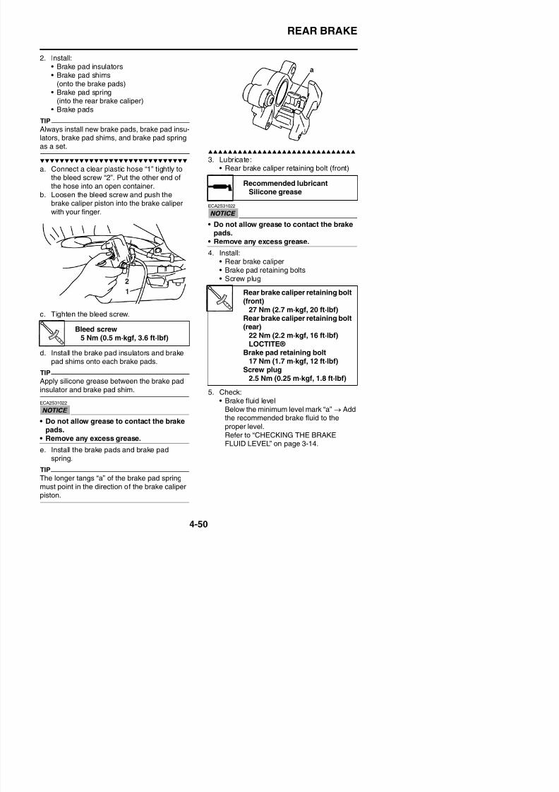
8/21/2019 Fz8 - Service Manual
http://slidepdf.com/reader/full/fz8-service-manual 217/609
with your finger.
c. Tighten the bleed screw.
d. Install the brake pad insulators and brakepad shims onto each brake pads.
TIP
Apply silicone grease between the brake padinsulator and brake pad shim.
• Do not allow grease to contact the brakepads.
• Remove any excess grease.4. Install:
• Rear brake caliper• Brake pad retaining bolts• Screw plug
5 Check:
Bleed screw5 Nm (0.5 m·kgf, 3.6 ft·lbf)
Rear brake caliper retaining bolt(front)
27 Nm (2.7 m·kgf, 20 ft·lbf)Rear brake caliper retaining bolt(rear)
22 Nm (2.2 m·kgf, 16 ft·lbf)LOCTITE®
Brake pad retaining bolt17 Nm (1.7 m·kgf, 12 ft·lbf)
Screw plug
2.5 Nm (0.25 m·kgf, 1.8 ft·lbf)
REAR BRAKE
6. Check:• Brake pedal operation
Soft or spongy feeling → Bleed the brake
system.Refer to “BLEEDING THE HYDRAULICBRAKE SYSTEM” on page 3-16.
EAS22590
REMOVING THE REAR BRAKE CALIPER
a. Blow compressed air into the brake hose joint opening “a” to force out the piston fromthe brake caliper.
WARNINGEWA13550
• Cover the brake caliper piston with a rag.Be careful not to get injured when the pis-ton is expelled from the brake caliper.
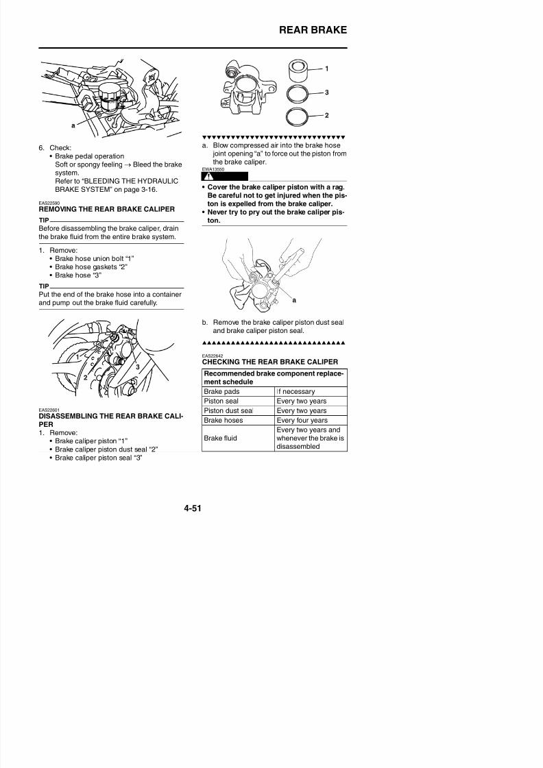
8/21/2019 Fz8 - Service Manual
http://slidepdf.com/reader/full/fz8-service-manual 218/609
REMOVING THE REAR BRAKE CALIPER
TIP
Before disassembling the brake caliper, drain
the brake fluid from the entire brake system.
1. Remove:• Brake hose union bolt “1”• Brake hose gaskets “2”• Brake hose “3”
TIP
Put the end of the brake hose into a container
and pump out the brake fluid carefully.
• Never try to pry out the brake caliper pis-ton.
b. Remove the brake caliper piston dust sealand brake caliper piston seal.
EAS22642
CHECKING THE REAR BRAKE CALIPER
Recommended brake component replace-ment schedule
REAR BRAKE
1. Check:• Brake caliper piston “1”
Rust/scratches/wear → Replace thebrake caliper piston.
• Brake caliper cylinder “2”Scratches/wear → Replace the brake cal-iper assembly.
• Brake caliper body “3”Cracks/damage → Replace the brakecaliper assembly.
• Brake fluid delivery passages(brake caliper body)Obstruction → Blow out with compressedair.
WARNING
EWA39P1402
Whenever a brake caliper is disassembled,replace the brake caliper piston dust sealand brake caliper piston seal.
• Whenever a brake caliper is disassem-bled, replace the brake caliper piston dustseal and brake caliper piston seal.
EAS22670
INSTALLING THE REAR BRAKE CALIPER1. Install:
• Rear brake caliper “1”(temporarily)
• Brake hose gaskets
• Brake hose “2”• Brake hose union bolt “3”
Recommended fluidDOT 4
Brake hose union bolt30 Nm (3.0 m·kgf, 22 ft·lbf)
New
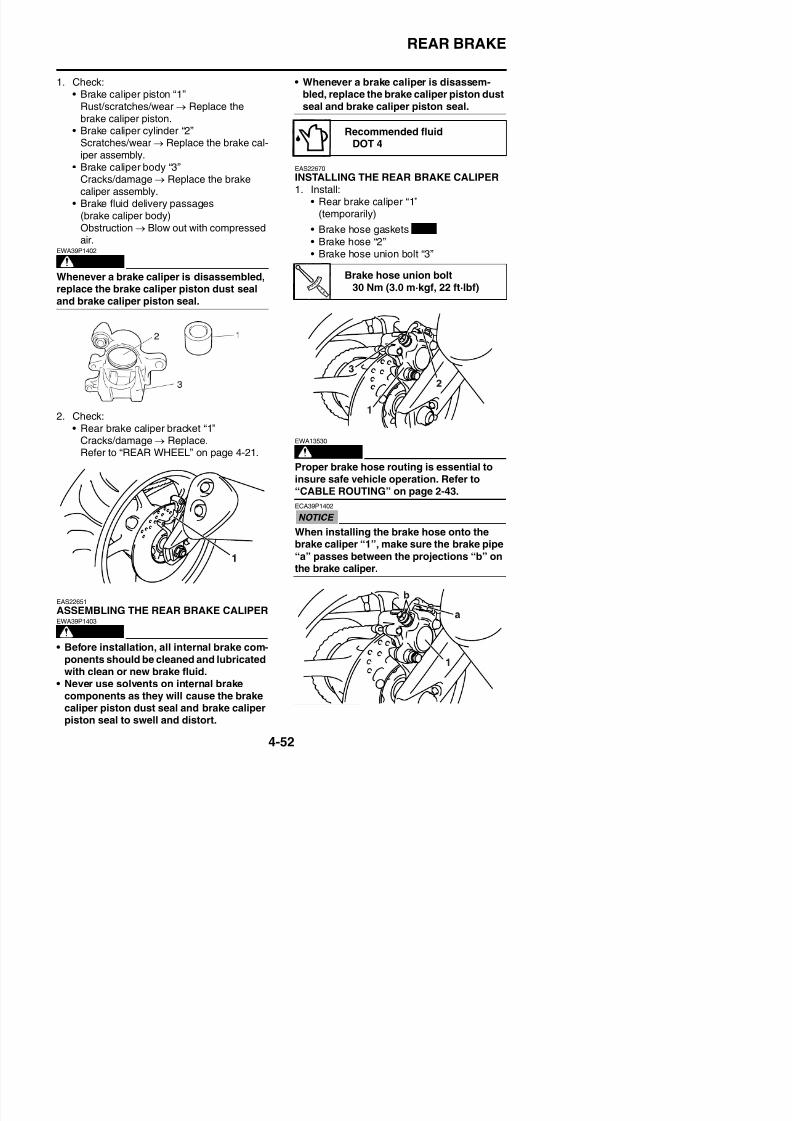
8/21/2019 Fz8 - Service Manual
http://slidepdf.com/reader/full/fz8-service-manual 219/609
p p
2. Check:• Rear brake caliper bracket “1”
Cracks/damage → Replace.Refer to “REAR WHEEL” on page 4-21. WARNINGEWA13530
Proper brake hose routing is essential toinsure safe vehicle operation. Refer to“CABLE ROUTING” on page 2-43.
ECA39P1402
When installing the brake hose onto the
brake caliper “1”, make sure the brake pipe“a” passes between the projections “b” on
REAR BRAKE
2. Remove:• Rear brake caliper
3. Install:• Brake pad insulators• Brake pad shims
(onto the brake pads)
• Brake pad spring(into the rear brake caliper)
• Brake pads• Rear brake caliper
Refer to “REPLACING THE REARBRAKE PADS” on page 4-49.
5. Bleed:• Brake system
Refer to “BLEEDING THE HYDRAULICBRAKE SYSTEM” on page 3-16.
6. Check:• Brake fluid level
Below the minimum level mark “a” → Addthe recommended brake fluid to theproper level.Refer to “CHECKING THE BRAKEFLUID LEVEL” on page 3-14.
Rear brake caliper retaining bolt
(front)27 Nm (2.7 m·kgf, 20 ft·lbf)
Rear brake caliper retaining bolt(rear)
22 Nm (2.2 m·kgf, 16 ft·lbf)LOCTITE®
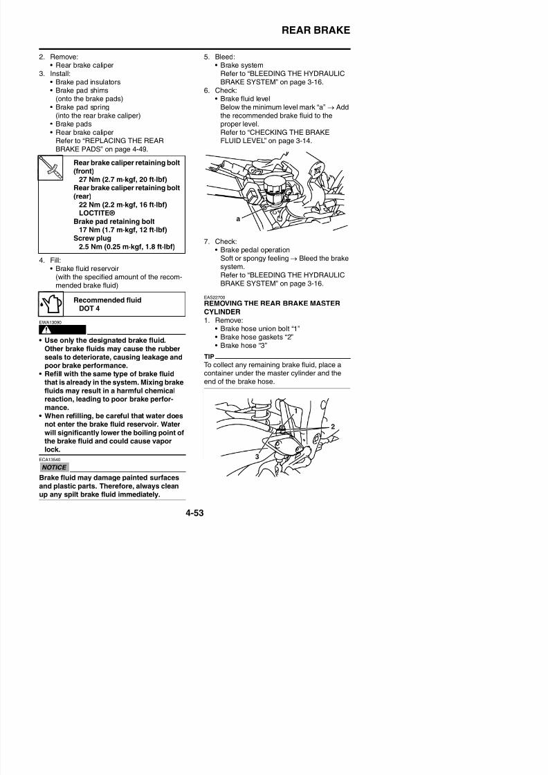
8/21/2019 Fz8 - Service Manual
http://slidepdf.com/reader/full/fz8-service-manual 220/609
4. Fill:• Brake fluid reservoir
(with the specified amount of the recom-mended brake fluid)
WARNING
EWA13090
• Use only the designated brake fluid.Other brake fluids may cause the rubberseals to deteriorate, causing leakage andpoor brake performance.
• Refill with the same type of brake fluidthat is already in the system. Mixing brake
7. Check:• Brake pedal operation
Soft or spongy feeling → Bleed the brakesystem.Refer to “BLEEDING THE HYDRAULICBRAKE SYSTEM” on page 3-16.
EAS22700
REMOVING THE REAR BRAKE MASTERCYLINDER1. Remove:
• Brake hose union bolt “1”• Brake hose gaskets “2”• Brake hose “3”
TIP
To collect any remaining brake fluid, place a
container under the master cylinder and theend of the brake hose.
LOCTITE® Brake pad retaining bolt
17 Nm (1.7 m·kgf, 12 ft·lbf)
Screw plug2.5 Nm (0.25 m·kgf, 1.8 ft·lbf)
Recommended fluid
DOT 4
REAR BRAKE
EAS22720
CHECKING THE REAR BRAKE MASTERCYLINDER1. Check:
• Brake master cylinderDamage/scratches/wear → Replace.
• Brake fluid delivery passages(brake master cylinder body)
Obstruction → Blow out with compressedair.
2. Check:• Brake master cylinder kit
Damage/scratches/wear → Replace.3. Check:
• Brake fluid reservoir “1”• Brake fluid reservoir diaphragm holder “2”
Cracks/damage → Replace.• Brake fluid reservoir diaphragm “3”
Damage/wear → Replace.
• Never use solvents on internal brakecomponents.
1. Install:
• Brake master cylinder kit
EAS22740
INSTALLING THE REAR BRAKE MASTERCYLINDER1. Install:
• Brake hose gaskets
• Brake hose• Brake fluid reservoir hose• Brake hose union bolt
Recommended fluidDOT 4
Brake hose union bolt30 Nm (3 0 m kgf 22 ft lbf)
New
New
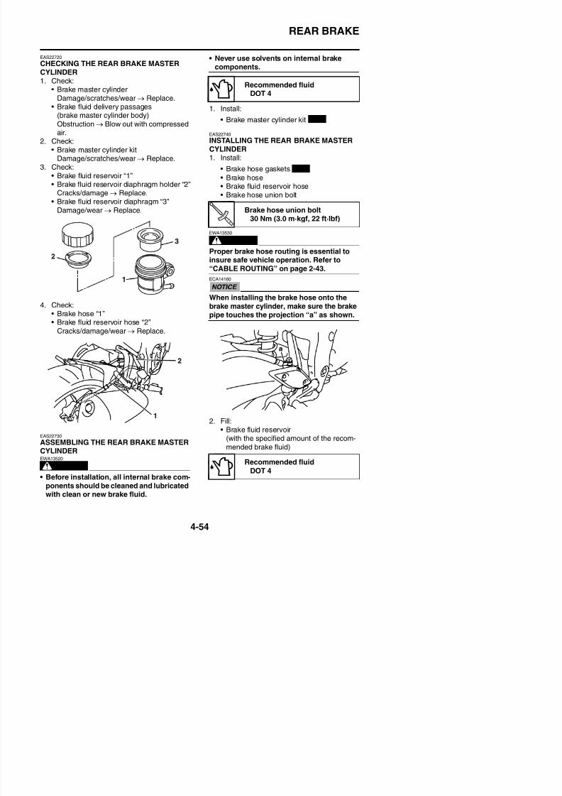
8/21/2019 Fz8 - Service Manual
http://slidepdf.com/reader/full/fz8-service-manual 221/609
4. Check:
• Brake hose “1”• Brake fluid reservoir hose “2”
Cracks/damage/wear → Replace.
WARNING
EWA13530
Proper brake hose routing is essential toinsure safe vehicle operation. Refer to“CABLE ROUTING” on page 2-43.
ECA14160
When installing the brake hose onto thebrake master cylinder, make sure the brake
pipe touches the projection “a” as shown.
30 Nm (3.0 m·kgf, 22 ft·lbf)
REAR BRAKE
WARNING
EWA13090
• Use only the designated brake fluid.Other brake fluids may cause the rubberseals to deteriorate, causing leakage andpoor brake performance.
• Refill with the same type of brake fluidthat is already in the system. Mixing brake
fluids may result in a harmful chemicalreaction, leading to poor brake perfor-mance.
• When refilling, be careful that water doesnot enter the brake fluid reservoir. Waterwill significantly lower the boiling point of
the brake fluid and could cause vaporlock.
ECA13540
Brake fluid may damage painted surfaces
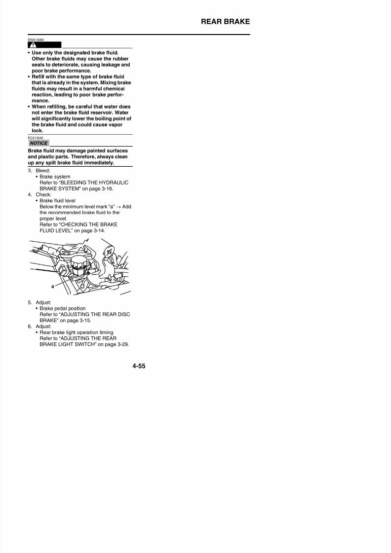
8/21/2019 Fz8 - Service Manual
http://slidepdf.com/reader/full/fz8-service-manual 222/609
y g pand plastic parts. Therefore, always cleanup any spilt brake fluid immediately.
3. Bleed:• Brake system
Refer to “BLEEDING THE HYDRAULICBRAKE SYSTEM” on page 3-16.
4. Check:• Brake fluid level
Below the minimum level mark “a” → Addthe recommended brake fluid to the
proper level.Refer to “CHECKING THE BRAKEFLUID LEVEL” on page 3-14.
ABS (ANTI-LOCK BRAKE SYSTEM)
EAS22760
ABS (ANTI-LOCK BRAKE SYSTEM)
Removing the hydraulic unit assembly
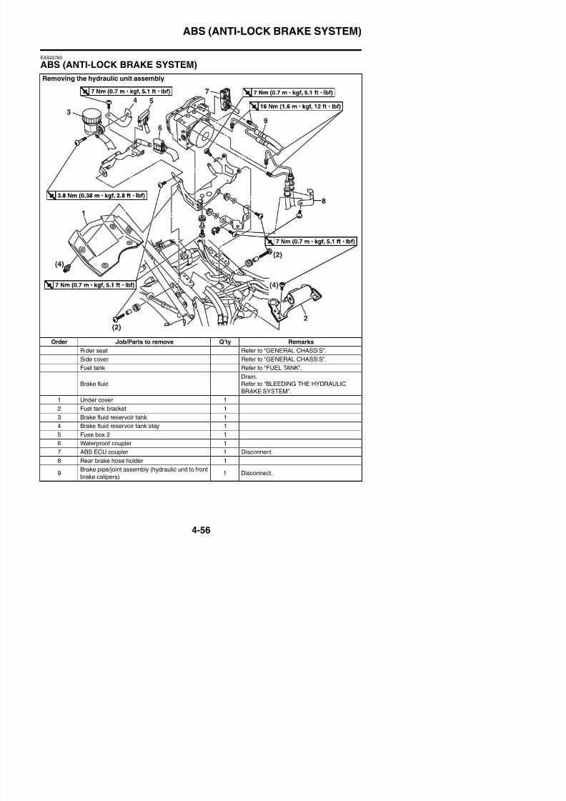
8/21/2019 Fz8 - Service Manual
http://slidepdf.com/reader/full/fz8-service-manual 223/609
Order Job/Parts to remove Q’ty Remarks
Rider seat Refer to “GENERAL CHASSIS”.
Side cover Refer to “GENERAL CHASSIS”.
Fuel tank Refer to “FUEL TANK”.
Brake fluidDrain.Refer to “BLEEDING THE HYDRAULIC
BRAKE SYSTEM”.
ABS (ANTI-LOCK BRAKE SYSTEM)
Removing the hydraulic unit assembly
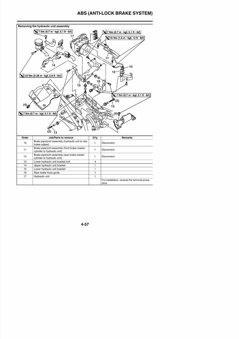
8/21/2019 Fz8 - Service Manual
http://slidepdf.com/reader/full/fz8-service-manual 224/609
Order Job/Parts to remove Q’ty Remarks
10Brake pipe/joint assembly (hydraulic unit to rear
brake caliper)1 Disconnect.
11Brake pipe/joint assembly (front brake master
cylinder to hydraulic unit)1 Disconnect.
12Brake pipe/joint assembly (rear brake master
cylinder to hydraulic unit)1 Disconnect.
13 Lower hydraulic unit bracket bolt 4
14 Upper hydraulic unit bracket 1
ABS (ANTI-LOCK BRAKE SYSTEM)
EAS4B56004
REMOVING THE HYDRAULIC UNIT ASSEM-BLYECA4B56013
Unless necessary, avoid removing and
installing the brake pipes of the hydraulicunit assembly.
WARNING
EWA13930
Refill with the same type of brake fluid thatis already in the system. Mixing fluids mayresult in a harmful chemical reaction, lead-ing to poor braking performance.
ECA4B56014
• Handle the ABS components with care,since they have been accurately adjusted.Keep them away from dirt and do not sub-j h h k
2. Disconnect:• ABS ECU coupler “1”
TIP
Pull up the coupler ejection slider to discon-nect the ABS ECU coupler.
3. Remove:• Hydraulic unit assembly “1”
TIP
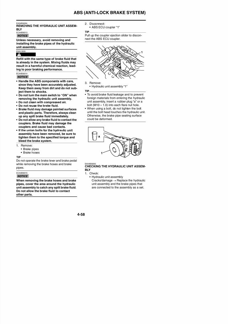
8/21/2019 Fz8 - Service Manual
http://slidepdf.com/reader/full/fz8-service-manual 225/609
ject them to shocks.• Do not turn the main switch to “ON” when
removing the hydraulic unit assembly.• Do not clean with compressed air.• Do not reuse the brake fluid.• Brake fluid may damage painted surfaces
and plastic parts. Therefore, always cleanup any spilt brake fluid immediately.
• Do not allow any brake fluid to contact thecouplers. Brake fluid may damage thecouplers and cause bad contacts.
• If the union bolts for the hydraulic unitassembly have been removed, be sure totighten them to the specified torque andbleed the brake system.
1. Remove:
• Brake pipes• Brake hoses
TIPDo not operate the brake lever and brake pedal
TIP
• To avoid brake fluid leakage and to preventforeign materials from entering the hydraulic
unit assembly, insert a rubber plug “a” or abolt (M10 × 1.0) into each flare nut hole.
• When using a bolt, do not tighten the boltuntil the bolt head touches the hydraulic unit.Otherwise, the brake pipe seating surfacecould be deformed.
ABS (ANTI-LOCK BRAKE SYSTEM)
EAS4B56006
CHECKING THE BRAKE PIPESThe following procedure applies to all of thebrake pipes.1. Check:
• Brake pipe end (flare nut)
Damage → Replace the hydraulic unit,brake pipes, and related parts as a set.
EAS4B56007
INSTALLING THE HYDRAULIC UNITASSEMBLY1. Install:
4. Install:• Brake pipe/joint assemblies “1”• Brake pipe/joint assembly flare nuts “2”
ECA4B56017
If the brake pipe flare nut does not turn eas-ily, replace the hydraulic unit, brake pipes,and related parts as a set.
Brake pipe/joint assembly flarenut
16 Nm (1.6 m·kgf, 12 ft·lbf)
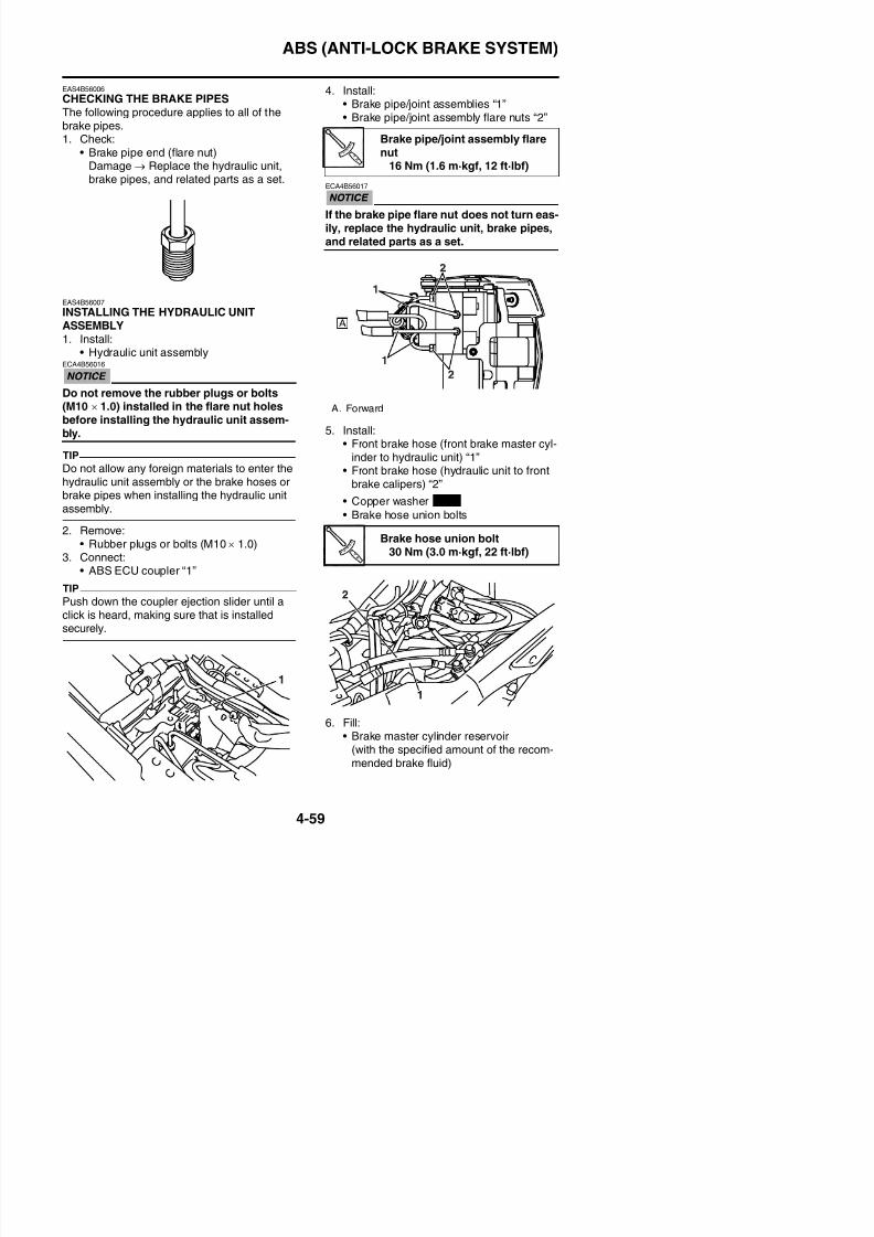
8/21/2019 Fz8 - Service Manual
http://slidepdf.com/reader/full/fz8-service-manual 226/609
• Hydraulic unit assemblyECA4B56016
Do not remove the rubber plugs or bolts(M10 × 1.0) installed in the flare nut holesbefore installing the hydraulic unit assem-bly.
TIP
Do not allow any foreign materials to enter thehydraulic unit assembly or the brake hoses or
brake pipes when installing the hydraulic unitassembly.
2. Remove:• Rubber plugs or bolts (M10 × 1.0)
3. Connect:• ABS ECU coupler “1”
TIP
Push down the coupler ejection slider until aclick is heard making sure that is installed
5. Install:• Front brake hose (front brake master cyl-
inder to hydraulic unit) “1”• Front brake hose (hydraulic unit to front
brake calipers) “2”
• Copper washer
• Brake hose union bolts
A. Forward
Brake hose union bolt30 Nm (3.0 m·kgf, 22 ft·lbf)
New
ABS (ANTI-LOCK BRAKE SYSTEM)
WARNING
EWA13090
• Use only the designated brake fluid.Other brake fluids may cause the rubberseals to deteriorate, causing leakage andpoor brake performance.
• Refill with the same type of brake fluidthat is already in the system. Mixing brakefluids may result in a harmful chemicalreaction, leading to poor brake perfor-
mance.• When refilling, be careful that water doesnot enter the brake fluid reservoir. Waterwill significantly lower the boiling point ofthe brake fluid and could cause vaporlock.
• Hydraulic unit operation test 1: this testchecks the function of the ABS after the sys-tem was disassembled, adjusted, or ser-viced.
• Hydraulic unit operation test 2: this test gen-erates the same reaction-force pulsating
action that is generated in the brake leverand brake pedal when the ABS is activated.
Hydraulic unit operation test 1
WARNING
EWA13120
Securely support the vehicle so that thereis no danger of it falling over.
1. Place the vehicle on the sidestand.2. Turn the main switch to “OFF”.3. Remove:
• Passenger seat
• Rider seatRefer to “GENERAL CHASSIS” on page
Recommended fluidDOT 4
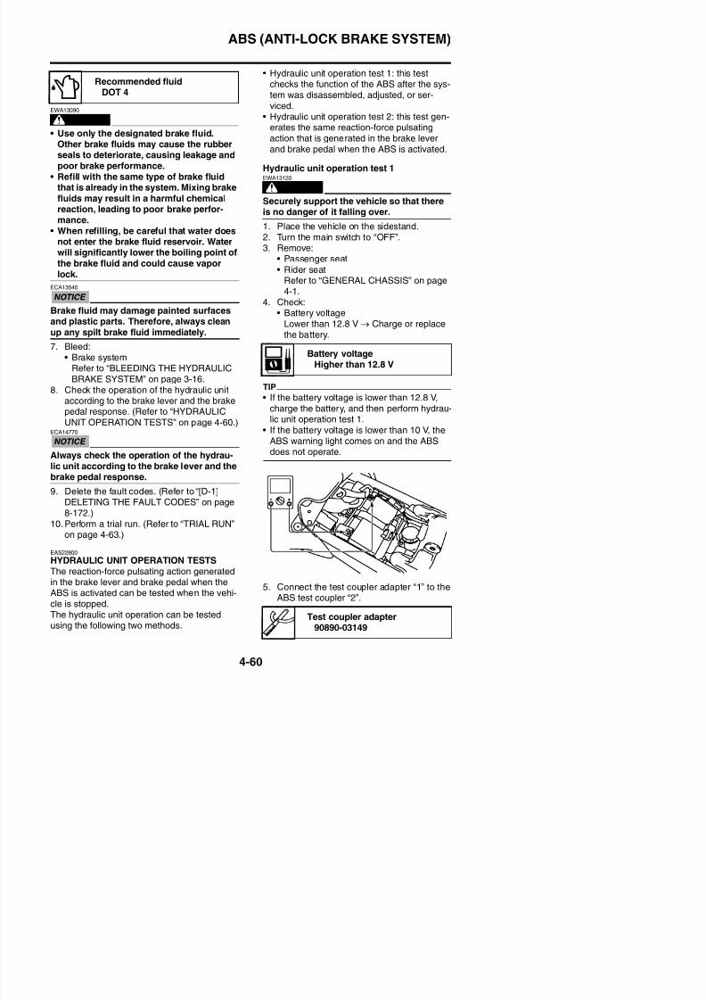
8/21/2019 Fz8 - Service Manual
http://slidepdf.com/reader/full/fz8-service-manual 227/609
ECA13540
Brake fluid may damage painted surfacesand plastic parts. Therefore, always cleanup any spilt brake fluid immediately.
7. Bleed:• Brake system
Refer to “BLEEDING THE HYDRAULICBRAKE SYSTEM” on page 3-16.
8. Check the operation of the hydraulic unit
according to the brake lever and the brakepedal response. (Refer to “HYDRAULICUNIT OPERATION TESTS” on page 4-60.)
ECA14770
Always check the operation of the hydrau-lic unit according to the brake lever and thebrake pedal response.
9. Delete the fault codes. (Refer to “[D-1]
Refer to GENERAL CHASSIS on page4-1.
4. Check:
• Battery voltageLower than 12.8 V → Charge or replacethe battery.
TIP
• If the battery voltage is lower than 12.8 V,charge the battery, and then perform hydrau-lic unit operation test 1.
• If the battery voltage is lower than 10 V, theABS warning light comes on and the ABSdoes not operate.
Battery voltageHigher than 12.8 V
ABS (ANTI-LOCK BRAKE SYSTEM)
6. Turn the main switch to “ON” while operat-ing the brake lever and then brake pedalsimultaneously.
TIPDo not push the start switch when turning themain switch to “ON”, otherwise the operationtest will not begin.
ECA4B56019
• Check that the pulse is felt in the frontbrake lever, rear brake pedal, and again inthe front brake lever, in this order.
• If the pulse is felt in the rear brake pedal
before it is felt in the front brake lever,check that the brake hoses and brake
pipes are connected correctly to thehydraulic unit assembly.
• If the pulse is hardly felt in either thebrake lever or brake pedal, check that thebrake hoses and brake pipes are con-nected correctly to the hydraulic unit
assembly.
• If the operation of the hydraulic unit isnormal, delete all of the fault codes.
Hydraulic unit operation test 2EWA13120
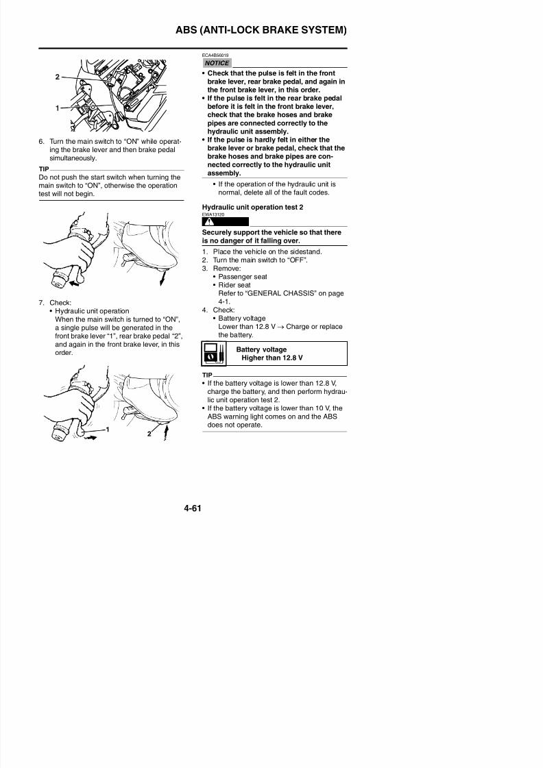
8/21/2019 Fz8 - Service Manual
http://slidepdf.com/reader/full/fz8-service-manual 228/609
7. Check:• Hydraulic unit operationWhen the main switch is turned to “ON”,a single pulse will be generated in thefront brake lever “1”, rear brake pedal “2”,and again in the front brake lever, in thisorder.
WARNING
Securely support the vehicle so that there
is no danger of it falling over.
1. Place the vehicle on the sidestand.2. Turn the main switch to “OFF”.3. Remove:
• Passenger seat• Rider seat
Refer to “GENERAL CHASSIS” on page4-1.
4. Check:• Battery voltage
Lower than 12.8 V → Charge or replacethe battery.
TIP
If h b l i l h V
Battery voltageHigher than 12.8 V
ABS (ANTI-LOCK BRAKE SYSTEM)
5. Connect the test coupler adapter “1” to theABS test coupler “2”. 10. A reaction-force pulsating action is gener-
ated in the front brake lever “1” 0.5 second
after the brake lever and brake pedal areoperated simultaneously and continues forapproximately 1.5 seconds.
TIP
• The reaction-force pulsating action consistsof quick pulses.B t ti ti th b k l
Test coupler adapter90890-03149
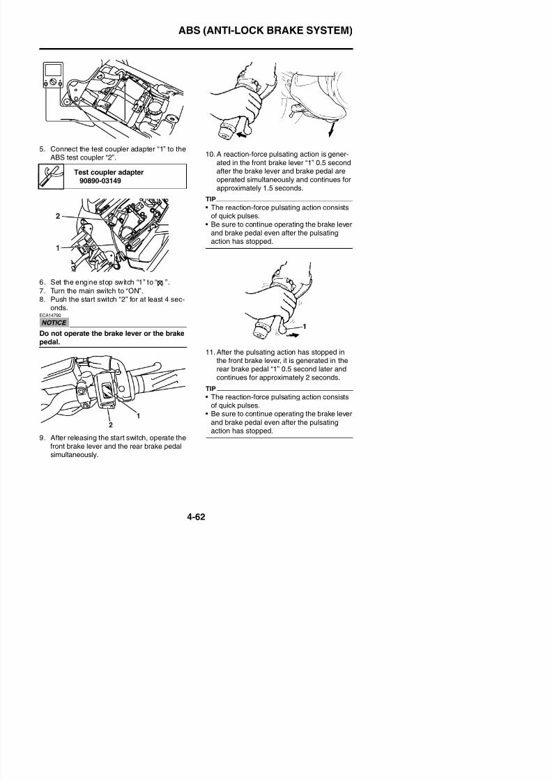
8/21/2019 Fz8 - Service Manual
http://slidepdf.com/reader/full/fz8-service-manual 229/609
6. Set the engine stop switch “1” to “ ”.
7. Turn the main switch to “ON”.8. Push the start switch “2” for at least 4 sec-
onds.ECA14790
Do not operate the brake lever or the brakepedal.
• Be sure to continue operating the brake leverand brake pedal even after the pulsating
action has stopped.
11. After the pulsating action has stopped inthe front brake lever, it is generated in therear brake pedal “1” 0.5 second later and
continues for approximately 2 seconds.TIP
ABS (ANTI-LOCK BRAKE SYSTEM)
12. After the pulsating action has stopped inthe rear brake pedal, it is generated in thefront brake lever 0.5 second later and con-tinues for approximately 1.5 seconds.
TIP
The reaction-force pulsating action consists of
quick pulses.
ECA4B56021
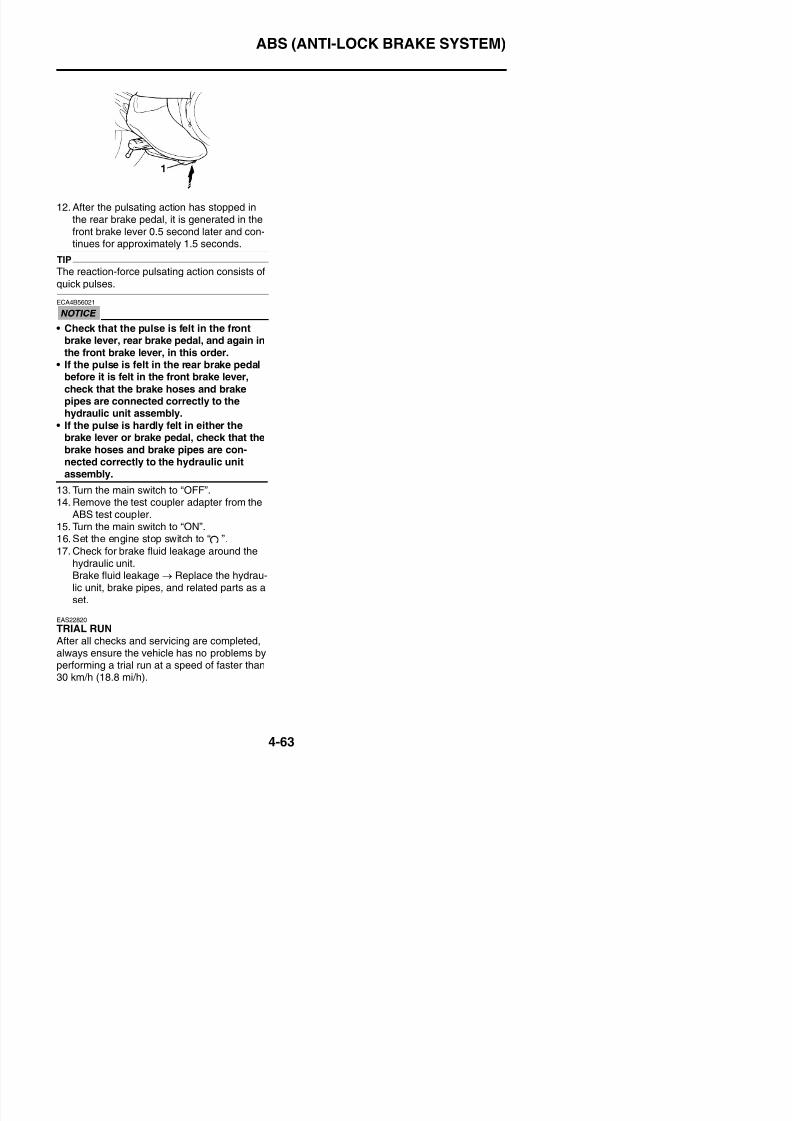
8/21/2019 Fz8 - Service Manual
http://slidepdf.com/reader/full/fz8-service-manual 230/609
• Check that the pulse is felt in the frontbrake lever, rear brake pedal, and again in
the front brake lever, in this order.• If the pulse is felt in the rear brake pedal
before it is felt in the front brake lever,
check that the brake hoses and brakepipes are connected correctly to thehydraulic unit assembly.
• If the pulse is hardly felt in either thebrake lever or brake pedal, check that the
brake hoses and brake pipes are con-nected correctly to the hydraulic unitassembly.
13. Turn the main switch to “OFF”.14. Remove the test coupler adapter from the
ABS test coupler.15. Turn the main switch to “ON”.
16. Set the engine stop switch to “ ”.17. Check for brake fluid leakage around the
HANDLEBAR
EAS22840
HANDLEBAR
Removing the handlebar
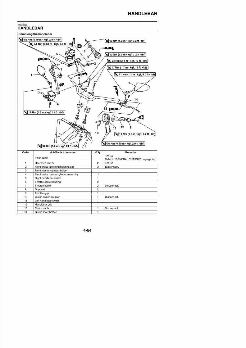
8/21/2019 Fz8 - Service Manual
http://slidepdf.com/reader/full/fz8-service-manual 231/609
Order Job/Parts to remove Q’ty Remarks
Inner panelFZ8SA
Refer to “GENERAL CHASSIS” on page 4-1.
1 Rear view mirror 2 FZ8NA
2 Front brake light switch connector 2 Disconnect.
3 Front master cylinder holder 1
HANDLEBAR
Removing the handlebar
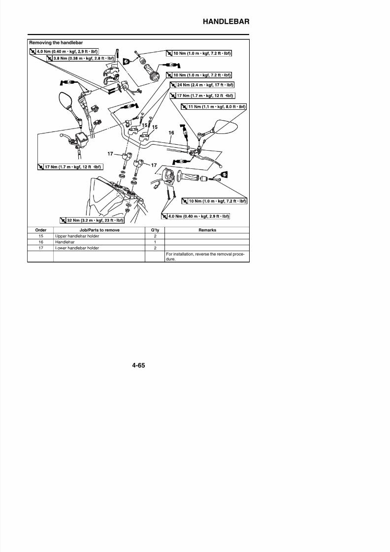
8/21/2019 Fz8 - Service Manual
http://slidepdf.com/reader/full/fz8-service-manual 232/609
Order Job/Parts to remove Q’ty Remarks
15 Upper handlebar holder 2
16 Handlebar 1
17 Lower handlebar holder 2
For installation, reverse the removal proce-dure.
HANDLEBAR
EAS22860
REMOVING THE HANDLEBAR1. Stand the vehicle on a level surface.
WARNING
EWA13120
Securely support the vehicle so that there
is no danger of it falling over.2. Remove:
• Handlebar grip “1”
TIP
Blow compressed air between the left handle-bar and the handlebar grip, and gradually pushthe grip off the handlebar.
EAS22931
INSTALLING THE HANDLEBAR
1. Stand the vehicle on a level surface.
WARNING
EWA13120
Securely support the vehicle so that thereis no danger of it falling over.
2. Install:• Lower handlebar holders
(temporarily)H dl b “1”
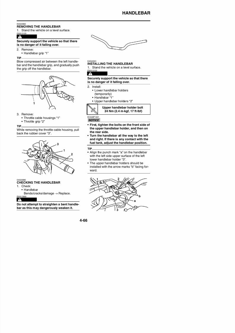
8/21/2019 Fz8 - Service Manual
http://slidepdf.com/reader/full/fz8-service-manual 233/609
3. Remove:• Throttle cable housings “1”• Throttle grip “2”
TIP
While removing the throttle cable housing, pull
back the rubber cover “3”.
• Handlebar “1”• Upper handlebar holders “2”
ECA39P1407
• First, tighten the bolts on the front side ofthe upper handlebar holder, and then on
the rear side.• Turn the handlebar all the way to the left
and right. If there is any contact with the
fuel tank, adjust the handlebar position.
TIP
• Align the punch mark “a” on the handlebarwith the left side upper surface of the leftlower handlebar holder “3”.
• The upper handlebar holders should be
Upper handlebar holder bolt24 Nm (2.4 m·kgf, 17 ft·lbf)
HANDLEBAR
3. Tighten:• Lower handlebar holder nuts
4. Install:• Throttle grip “1”
• Throttle cables• Throttle cable housings “2”• Grip end
TIP
• Align the projection “a” on the throttle cablehousing with the hole “b” in the handlebar.
• There should be 1–3 mm (0.04–0.12 in) ofclearance “c” between the throttle grip andthe grip end
7. Install:• Throttle cable clamp “1”
TIP
• Using side “a” of the master cylinder as aguide, install the clamp between side “a” andprotector “2” of the throttle cable (deceleratorcable) with the claw down and the damperfacing to the master cylinder.
• When clamping, protector “3” of the throttlecable (accelerator cable) should be on thethrottle grip side.
Lower handlebar holder nut32 Nm (3.2 m·kgf, 23 ft·lbf)
Grip end bolt10 Nm (1.0 m·kgf, 7.2 ft·lbf)LOCTITE®
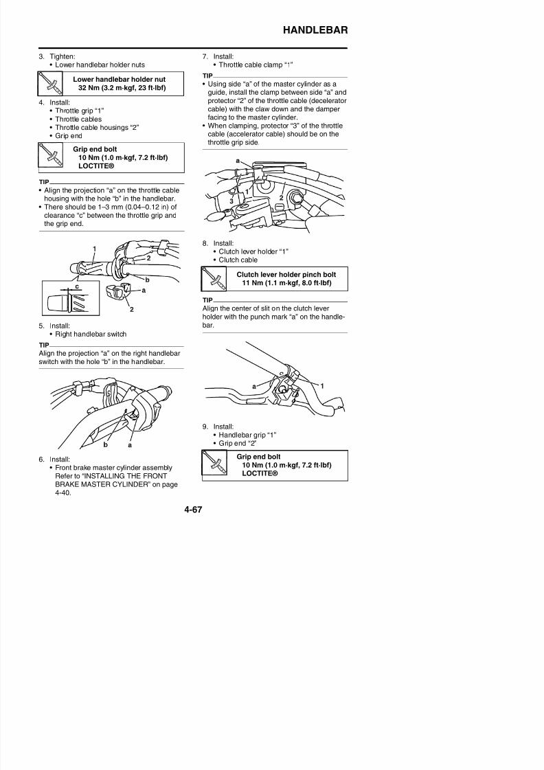
8/21/2019 Fz8 - Service Manual
http://slidepdf.com/reader/full/fz8-service-manual 234/609
the grip end.
5. Install:• Right handlebar switch
TIP
Align the projection “a” on the right handlebarswitch with the hole “b” in the handlebar.
8. Install:• Clutch lever holder “1”• Clutch cable
TIP
Align the center of slit on the clutch leverholder with the punch mark “a” on the handle-bar.
Clutch lever holder pinch bolt11 Nm (1.1 m·kgf, 8.0 ft·lbf)
HANDLEBAR
a. Apply a thin coat of rubber adhesive ontothe end of the left handlebar.
b. Side the handlebar grip over the end of theleft handlebar.
c. Wipe off any excess rubber adhesive with a
clean rag.
WARNING
EWA13700
Do not touch the handlebar grip until therubber adhesive has fully dried.
TIP
There should be 1–3 mm (0.04–0.12 in) of
clearance “a” between the handlebar grip andthe grip end.
12. Adjust:• Clutch cable free play
Refer to “ADJUSTING THE CLUTCHCABLE FREE PLAY” on page 3-13.
Clutch cable free play
10.0–15.0 mm (0.39–0.59 in)
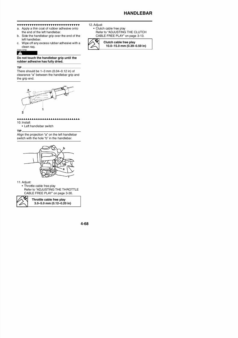
8/21/2019 Fz8 - Service Manual
http://slidepdf.com/reader/full/fz8-service-manual 235/609
10. Install:• Left handlebar switch
TIP
Align the projection “a” on the left handlebarswitch with the hole “b” in the handlebar.
FRONT FORK
EAS22950
FRONT FORK
Removing the front fork legs
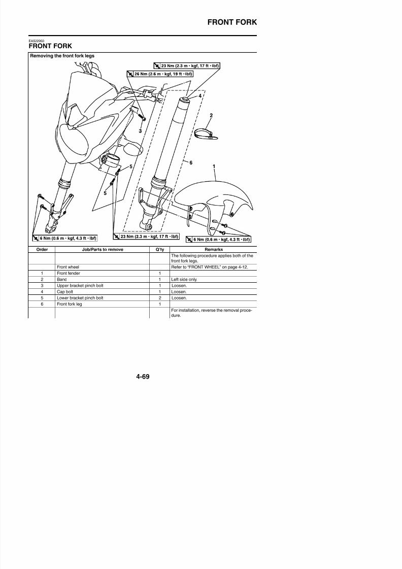
8/21/2019 Fz8 - Service Manual
http://slidepdf.com/reader/full/fz8-service-manual 236/609
Order Job/Parts to remove Q’ty Remarks
The following procedure applies both of the
front fork legs.
Front wheel Refer to “FRONT WHEEL” on page 4-12.
1 Front fender 1
2 Band 1 Left side only.
FRONT FORK
Disassembling the front fork legs
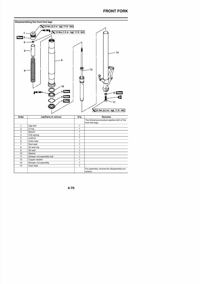
8/21/2019 Fz8 - Service Manual
http://slidepdf.com/reader/full/fz8-service-manual 237/609
Order Job/Parts to remove Q’ty Remarks
The following procedure applies both of the
front fork legs.
1 Cap bolt 1
2 O-ring 1
3 Spacer 1
4 Fork spring 1
5 Locknut 16 Outer tube 1
FRONT FORK
EAS22960
REMOVING THE FRONT FORK LEGSThe following procedure applies to both of thefront fork legs.1. Stand the vehicle on a level surface.
WARNING
EWA13120
Securely support the vehicle so that thereis no danger of it falling over.
TIP
Place the vehicle on a suitable stand so thatthe front wheel is elevated.
2. Loosen:
• Upper bracket pinch bolt “1”• Cap bolt “2”• Lower bracket pinch bolts “3”
WARNING
EWA13640
Before loosening the upper and lowerbracket pinch bolts, support the front fork
TIP
Use the side of the rod holder that is marked“B”.
Fork spring compressor90890-01441YM-01441
Rod holder90890-01434
Damper rod holder doubleended
YM-01434
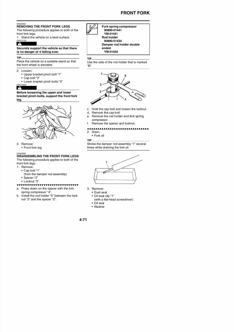
8/21/2019 Fz8 - Service Manual
http://slidepdf.com/reader/full/fz8-service-manual 238/609
leg.
3. Remove:• Front fork leg
EAS22990
DISASSEMBLING THE FRONT FORK LEGSThe following procedure applies to both of thefront fork legs.
c. Hold the cap bolt and loosen the locknut.d. Remove the cap bolt.e. Remove the rod holder and fork spring
compressor.f. Remove the spacer and locknut.
2. Drain:• Fork oil
TIP
Stroke the damper rod assembly “1” severaltimes while draining the fork oil.
FRONT FORK
ECA39P1404
Do not scratch the outer tube.
4. Remove:• Damper rod assembly bolt• Damper rod assembly
TIP
While holding the damper rod with the damperrod holder “1”, loosen the damper rod assem-bly bolt.
WARNING
EWA13650
Do not attempt to straighten a bent innertube as this may dangerously weaken it.
2. Measure:• Spring free length “a”Out of specification → Replace.
Fork spring free length286.1 mm (11.26 in)
Limit280.4 mm (11.04 in)
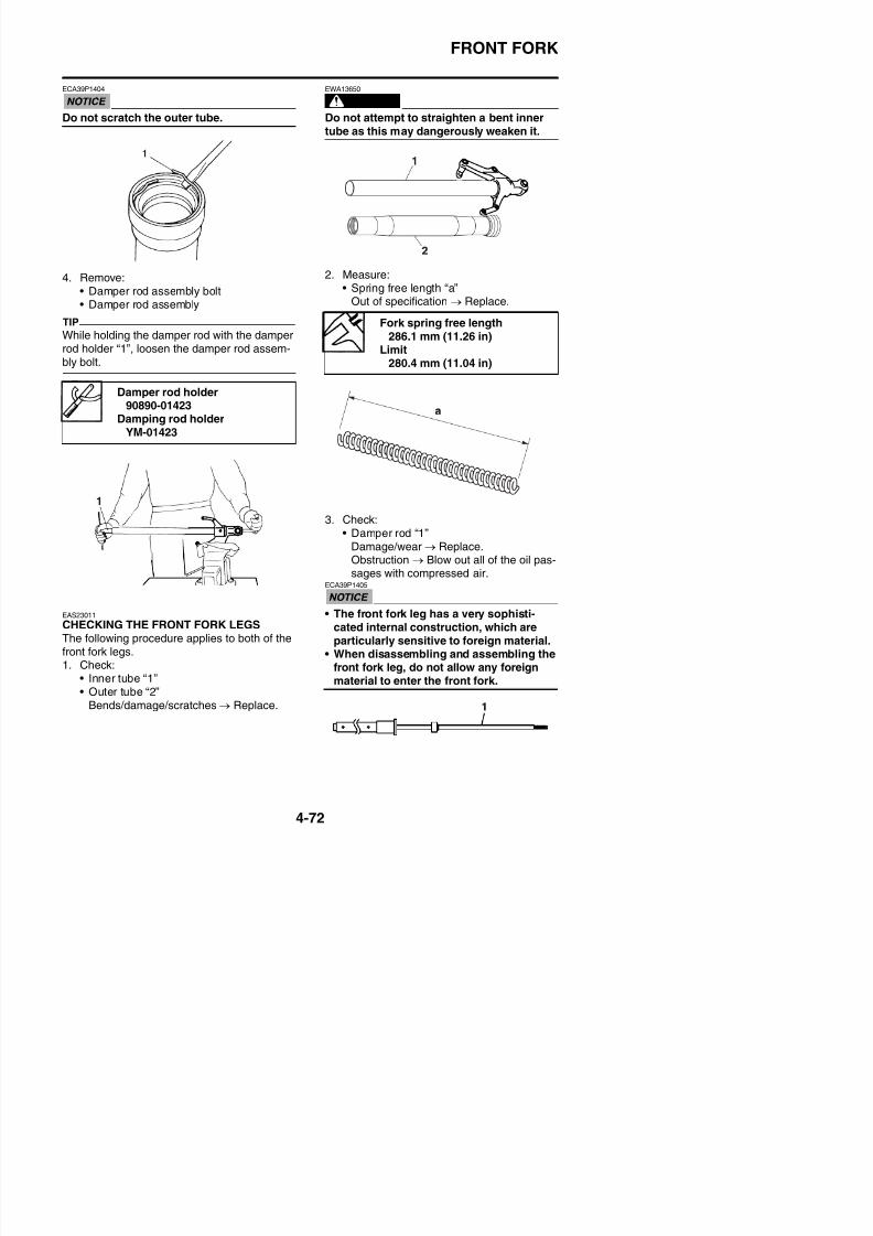
8/21/2019 Fz8 - Service Manual
http://slidepdf.com/reader/full/fz8-service-manual 239/609
y
EAS
3. Check:• Damper rod “1”
Damage/wear → Replace.Obstruction → Blow out all of the oil pas-sages with compressed air.
ECA39P1405
• The front fork leg has a very sophisti
Damper rod holder90890-01423
Damping rod holderYM-01423
( )
FRONT FORK
EAS23031
ASSEMBLING THE FRONT FORK LEGSThe following procedure applies to both of thefront fork legs.
WARNING
EWA39P1404
• Note that the amount of the fork oil is dif-ferent in the left and right front fork legs.Make sure to fill each of the left and rightfront fork legs with the specified amountof the fork oil.
• If both front fork legs are not filled withthe specified amount of the fork oil, it maycause poor handling and a loss of stabil-ity.
TIP
• When assembling the front fork leg, be sureto replace the following parts:- Oil seal- Oil seal clip- Dust seal
2. Tighten:• Damper rod assembly bolt
(along with the copper washer )
TIP
While holding the damper rod assembly withthe damper rod holder “1”, tighten the damper
A. Left side
B. Right side
Damper rod assembly bolt23 Nm (2.3 m·kgf, 17 ft·lbf)LOCTITE®
New
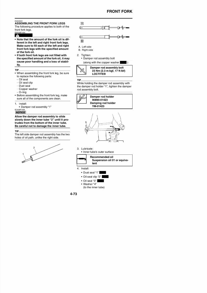
8/21/2019 Fz8 - Service Manual
http://slidepdf.com/reader/full/fz8-service-manual 240/609
- Copper washer
- O-ring• Before assembling the front fork leg, make
sure all of the components are clean.
1. Install:• Damper rod assembly “1”
ECA39P1406
Allow the damper rod assembly to slideslowly down the inner tube “2” until it pro-trudes from the bottom of the inner tube.Be careful not to damage the inner tube.
TIP
The left side damper rod assembly has the twoholes of oil path, unlike the right side.
p , g prod assembly bolt.
Damper rod holder90890-01423
Damping rod holderYM-01423
FRONT FORK
ECA14B1007
Make sure the numbered side of the oil sealfaces bottom side.
TIP
• Before installing the oil seal, lubricate its lipswith lithium-soap-based grease.• Lubricate the outer surface of the inner tube
with fork oil.
5. Install:
8. Install:• Dust seal “1”
(with the fork seal driver “2”)
Fork seal driver90890-01442
Adjustable fork seal driver (36–46 mm)
YM-01442
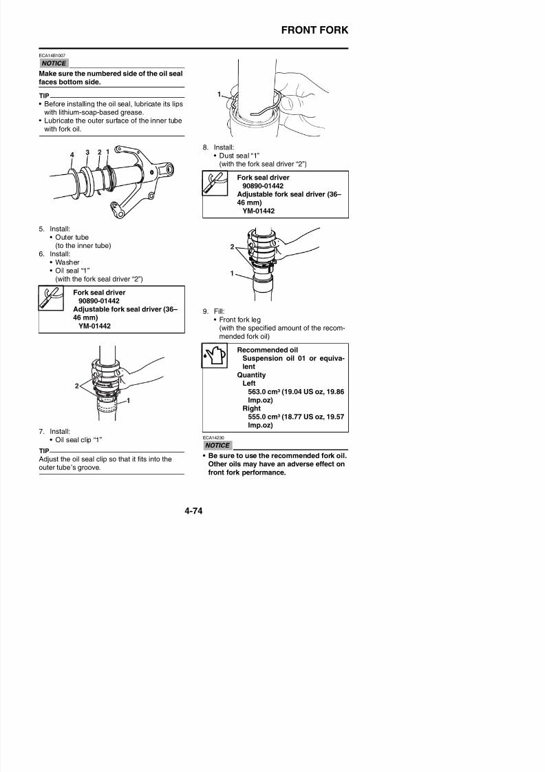
8/21/2019 Fz8 - Service Manual
http://slidepdf.com/reader/full/fz8-service-manual 241/609
• Outer tube(to the inner tube)
6. Install:• Washer• Oil seal “1”
(with the fork seal driver “2”)
9. Fill:• Front fork leg
(with the specified amount of the recom-mended fork oil)
Fork seal driver90890-01442
Adjustable fork seal driver (36–46 mm)
YM-01442
Recommended oilSuspension oil 01 or equiva-lent
QuantityLeft
FRONT FORK
• When disassembling and assembling thefront fork leg, do not allow any foreignmaterial to enter the front fork.
10. Install:• Rod puller “1”• Rod puller attachment (M10) “2”
(onto the damper rod “3”)
TIP
Be sure to bleed the front fork leg of any resid-ual air.
13. Measure:• Front fork leg oil level “a”
(from the top of the outer tube, with theouter tube fully compressed and withoutthe fork spring)Out of specification → Correct.
Rod puller90890-01437
Universal damping rod bleedingtool set
YM-A8703Rod puller attachment (M10)
90890-01436Universal damping rod bleedingtool set
YM-A8703
LevelLeft
82.0 mm (3.23 in)Right
85.0 mm (3.35 in)
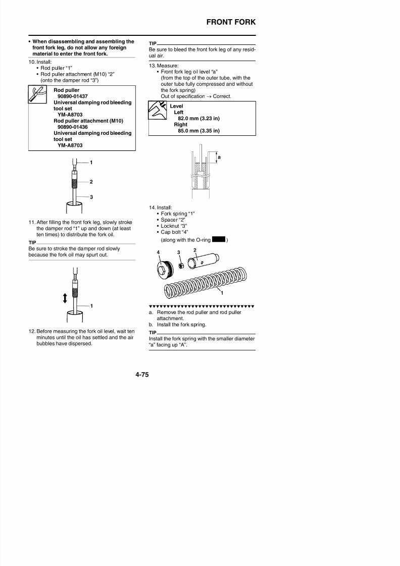
8/21/2019 Fz8 - Service Manual
http://slidepdf.com/reader/full/fz8-service-manual 242/609
11. After filling the front fork leg, slowly stroke
the damper rod “1” up and down (at leastten times) to distribute the fork oil.
TIP
Be sure to stroke the damper rod slowlybecause the fork oil may spurt out.
14. Install:• Fork spring “1”• Spacer “2”
• Locknut “3”• Cap bolt “4”
(along with the O-ring )New
FRONT FORK
c. Install the locknut all the way onto thedamper rod assembly.
d. Install the spacer.
e. Install the rod puller, rod puller attachment,and fork spring compressor.f. Press down on the spacer with the fork
spring compressor “1”.g. Pull up the rod puller and install the rod
holder “2” between the locknut “3” and thespacer “4”.
h. Remove the rod puller and rod pullerattachment.
i. Install the cap bolt all the way onto the
damper rod assembly, and finger tighten it.
WARNING
EWA13670
Always use a new cap bolt O-ring.
j. Hold the cap bolt “1” and tighten the locknut“2” to specification.
Locknut
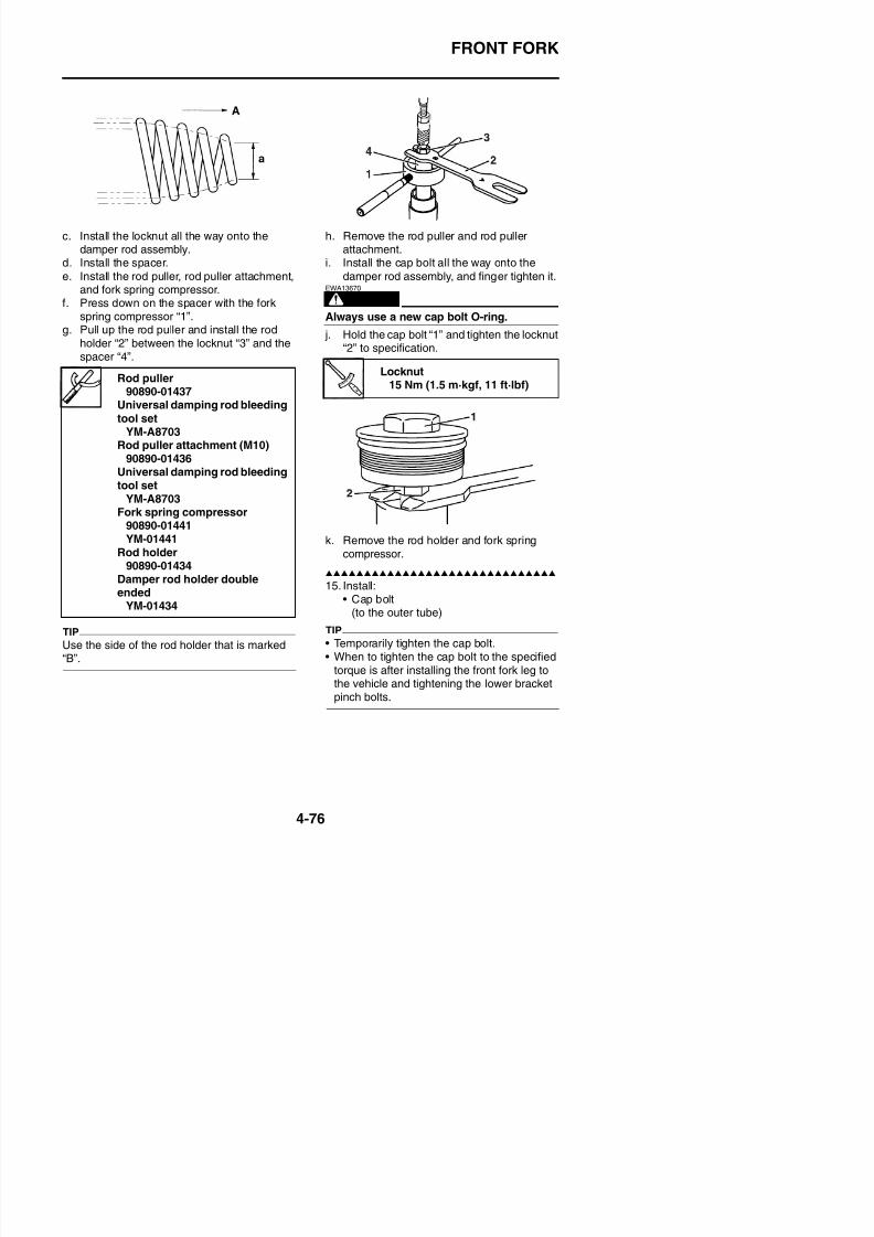
8/21/2019 Fz8 - Service Manual
http://slidepdf.com/reader/full/fz8-service-manual 243/609
k. Remove the rod holder and fork springcompressor.
15. Install:
• Cap bolt(to the outer tube)
Rod puller
90890-01437Universal damping rod bleeding
tool setYM-A8703
Rod puller attachment (M10)90890-01436
Universal damping rod bleedingtool set
YM-A8703Fork spring compressor
90890-01441YM-01441
Rod holder90890-01434
Damper rod holder doubleended
YM-01434
Locknut
15 Nm (1.5 m·kgf, 11 ft·lbf)
FRONT FORK
EAS23050
INSTALLING THE FRONT FORK LEGSThe following procedure applies to both of thefront fork legs.1. Install:
• Front fork legTemporarily tighten the upper and lowerbracket pinch bolts.
TIP
Make sure the outer tube is flush with the topof the upper bracket.
2. Tighten:• Lower bracket pinch bolts “1”
• Cap bolt “2”
U b k i h b l “ ”
Lower bracket pinch bolt23 Nm (2.3 m·kgf, 17 ft·lbf)
Cap bolt23 Nm (2.3 m·kgf, 17 ft·lbf)
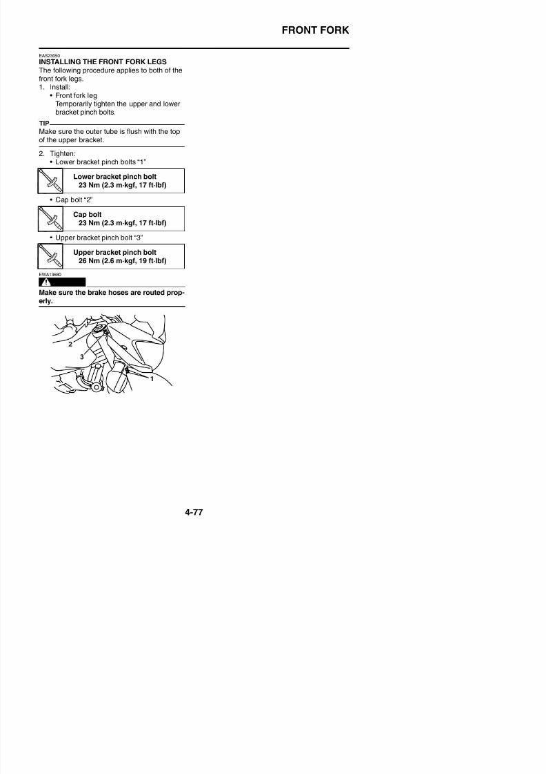
8/21/2019 Fz8 - Service Manual
http://slidepdf.com/reader/full/fz8-service-manual 244/609
• Upper bracket pinch bolt “3”
WARNING
EWA13680
Make sure the brake hoses are routed prop-erly.
Upper bracket pinch bolt26 Nm (2.6 m·kgf, 19 ft·lbf)
STEERING HEAD
EAS23090
STEERING HEAD
Removing the lower bracket (FZ8NA)
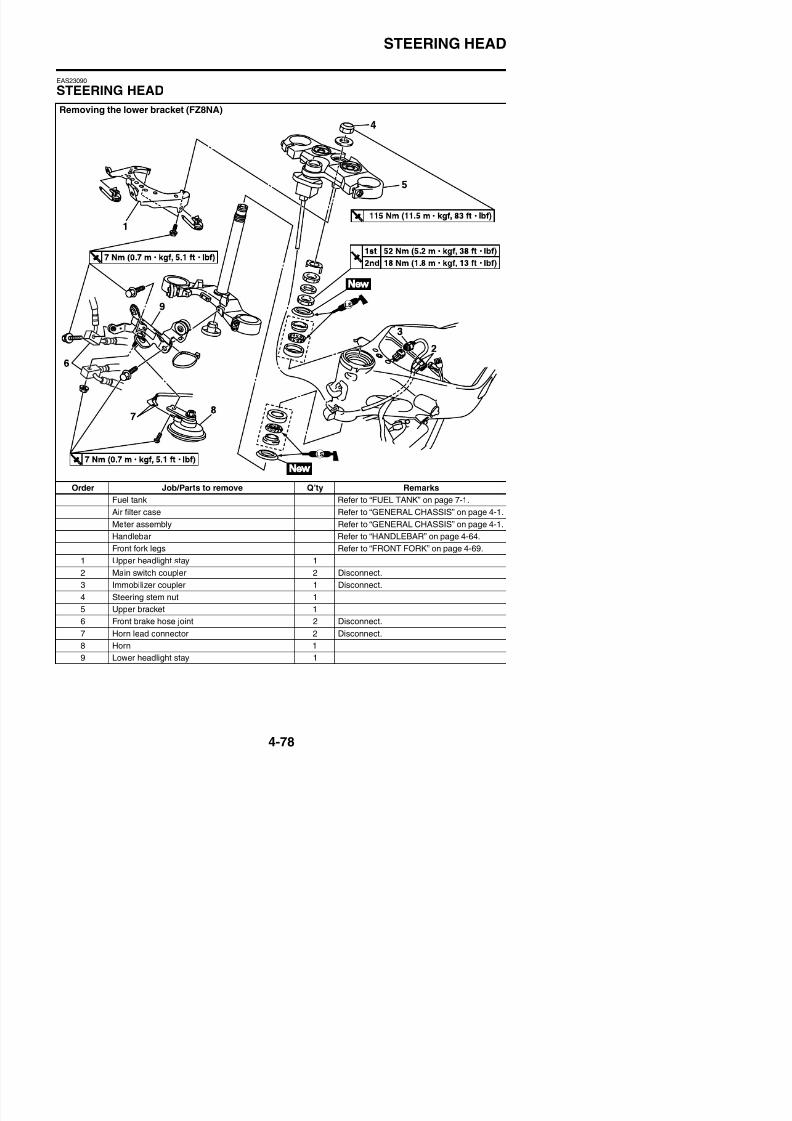
8/21/2019 Fz8 - Service Manual
http://slidepdf.com/reader/full/fz8-service-manual 245/609
Order Job/Parts to remove Q’ty Remarks
Fuel tank Refer to “FUEL TANK” on page 7-1.
Air filter case Refer to “GENERAL CHASSIS” on page 4-1.
Meter assembly Refer to “GENERAL CHASSIS” on page 4-1.
Handlebar Refer to “HANDLEBAR” on page 4-64.
Front fork legs Refer to “FRONT FORK” on page 4-69.
STEERING HEAD
Removing the lower bracket (FZ8NA)
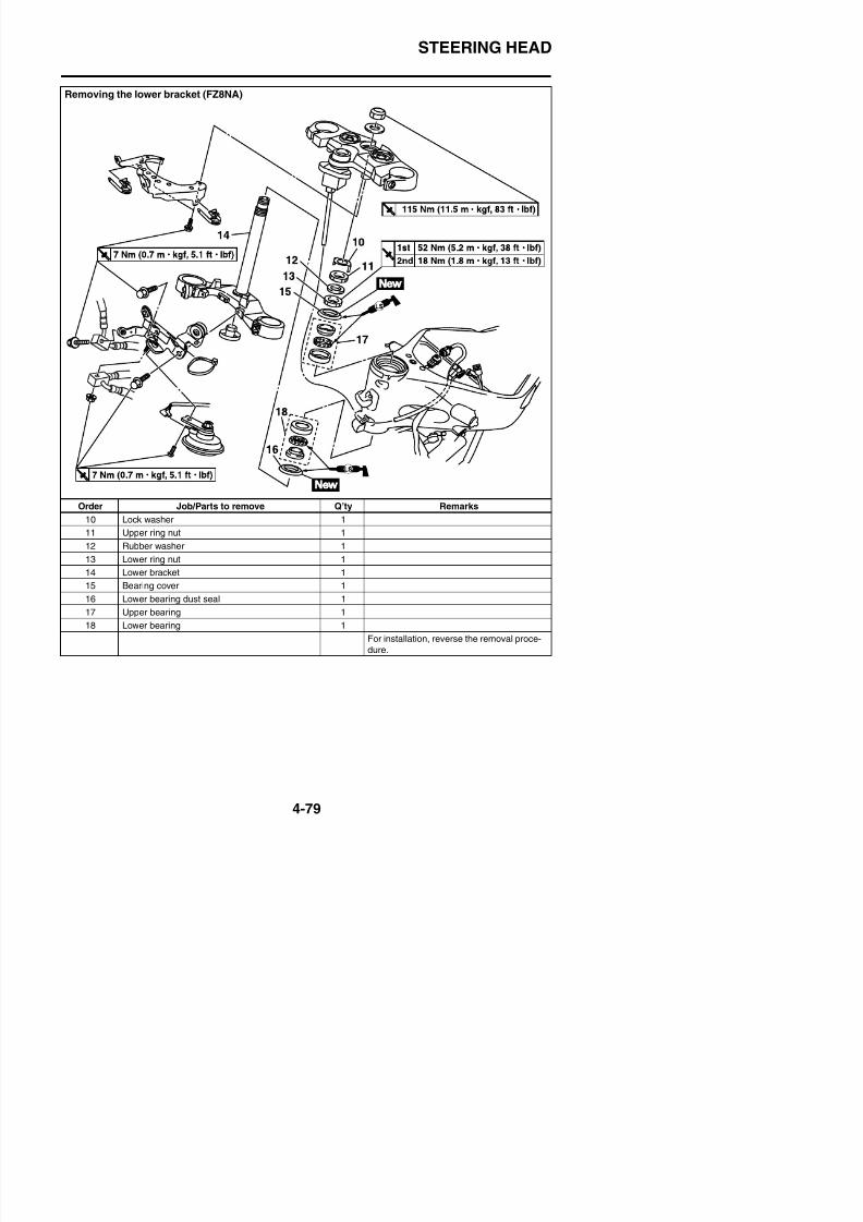
8/21/2019 Fz8 - Service Manual
http://slidepdf.com/reader/full/fz8-service-manual 246/609
Order Job/Parts to remove Q’ty Remarks
10 Lock washer 1
11 Upper ring nut 1
12 Rubber washer 1
13 Lower ring nut 1
14 Lower bracket 1
15 Bearing cover 1
16 Lower bearing dust seal 1
STEERING HEAD
Removing the lower bracket (FZ8SA)
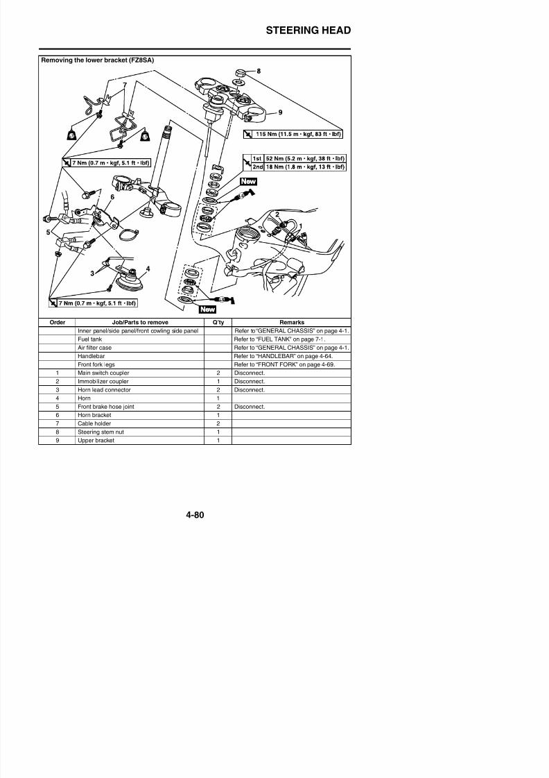
8/21/2019 Fz8 - Service Manual
http://slidepdf.com/reader/full/fz8-service-manual 247/609
Order Job/Parts to remove Q’ty Remarks
Inner panel/side panel/front cowling side panel Refer to “GENERAL CHASSIS” on page 4-1.
Fuel tank Refer to “FUEL TANK” on page 7-1.
Air filter case Refer to “GENERAL CHASSIS” on page 4-1.
Handlebar Refer to “HANDLEBAR” on page 4-64.
Front fork legs Refer to “FRONT FORK” on page 4-69.
1 Main switch coupler 2 Disconnect.
2 Immobilizer coupler 1 Disconnect.
STEERING HEAD
Removing the lower bracket (FZ8SA)

8/21/2019 Fz8 - Service Manual
http://slidepdf.com/reader/full/fz8-service-manual 248/609
Order Job/Parts to remove Q’ty Remarks
10 Lock washer 1
11 Upper ring nut 1
12 Rubber washer 1
13 Lower ring nut 1
14 Lower bracket 1
15 Bearing cover 1
16 Lower bearing dust seal 1
STEERING HEAD
EAS23110
REMOVING THE LOWER BRACKET1. Stand the vehicle on a level surface.
WARNING
EWA13120
Securely support the vehicle so that thereis no danger of it falling over.
2. Remove:• Upper ring nut• Rubber washer• Lower ring nut “1”• Lower bracket
WARNING
EWA13730
Securely support the lower bracket so thatthere is no danger of it falling.
TIP
• Hold the lower ring nut with steering nutwrench, and then remove the upper ring nutwith the ring nut wrench.
• Remove the lower ring nut with the steeringnut wrench “2”.
2. Check:• Bearings “1”• Bearing races “2”
Damage/pitting → Replace the bearingsand bearing races as a set.
3. Replace:• Bearings• Bearing races
a. Remove the bearing races from the steer-
ing head pipe “1” with a long rod “2” and
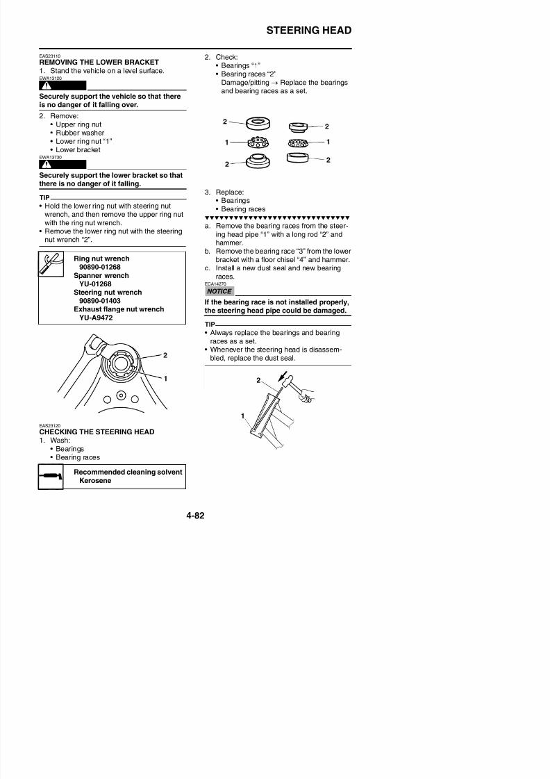
8/21/2019 Fz8 - Service Manual
http://slidepdf.com/reader/full/fz8-service-manual 249/609
nut wrench 2 .
hammer.b. Remove the bearing race “3” from the lowerbracket with a floor chisel “4” and hammer.
c. Install a new dust seal and new bearingraces.
ECA14270
If the bearing race is not installed properly,
the steering head pipe could be damaged.TIP
• Always replace the bearings and bearingraces as a set.
• Whenever the steering head is disassem-bled, replace the dust seal.
Ring nut wrench90890-01268
Spanner wrenchYU-01268
Steering nut wrench90890-01403
Exhaust flange nut wrenchYU-A9472
STEERING HEAD
4. Check:
• Upper bracket• Lower bracket
(along with the steering stem)Bends/cracks/damage → Replace.
EAS23140
INSTALLING THE STEERING HEAD1. Lubricate:
• Upper bearing• Lower bearing
TIP
Temporarily tighten the upper and lowerbracket pinch bolts.
5. Tighten:• Steering stem nut
Steering stem nut115 Nm (11.5 m·kgf, 83 ft·lbf)
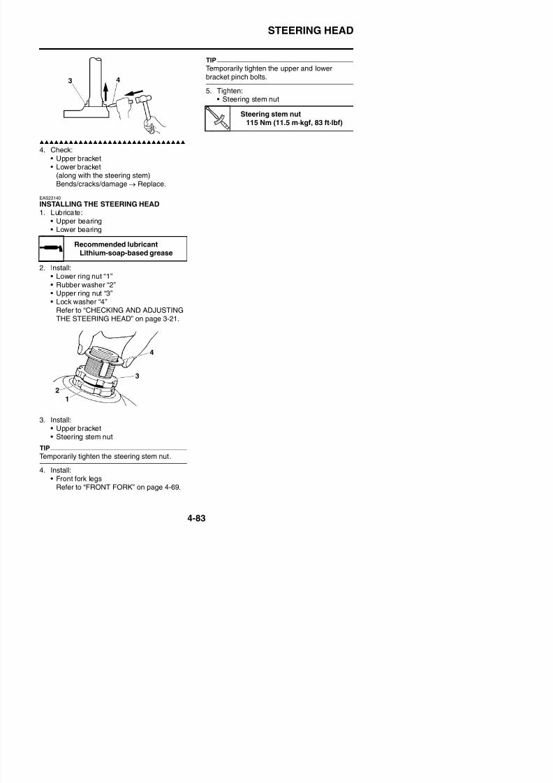
8/21/2019 Fz8 - Service Manual
http://slidepdf.com/reader/full/fz8-service-manual 250/609
2. Install:• Lower ring nut “1”
• Rubber washer “2”• Upper ring nut “3”• Lock washer “4”
Refer to “CHECKING AND ADJUSTINGTHE STEERING HEAD” on page 3-21.
Recommended lubricantLithium-soap-based grease
REAR SHOCK ABSORBER ASSEMBLY
EAS23160
REAR SHOCK ABSORBER ASSEMBLY
Removing the rear shock absorber assembly
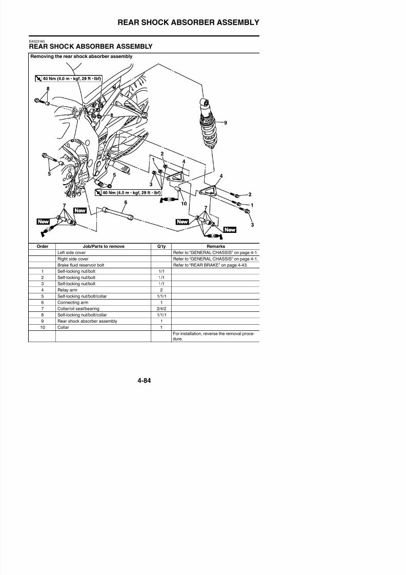
8/21/2019 Fz8 - Service Manual
http://slidepdf.com/reader/full/fz8-service-manual 251/609
Order Job/Parts to remove Q’ty Remarks
Left side cover Refer to “GENERAL CHASSIS” on page 4-1.
Right side cover Refer to “GENERAL CHASSIS” on page 4-1.
Brake fluid reservoir bolt Refer to “REAR BRAKE” on page 4-43.
1 Self-locking nut/bolt 1/1
2 Self-locking nut/bolt 1/1
3 Self-locking nut/bolt 1/1
REAR SHOCK ABSORBER ASSEMBLY
EAS23180
HANDLING THE REAR SHOCK ABSORBER
WARNING
EWA13740
This rear shock absorber contains highlycompressed nitrogen gas. Before handlingthe rear shock absorber, read and make
sure you understand the following informa-tion. The manufacturer cannot be heldresponsible for property damage or per-sonal injury that may result from improperhandling of the rear shock absorber.• Do not tamper or attempt to open the rear
shock absorber.• Do not subject the rear shock absorber to
an open flame or any other source of highheat. High heat can cause an explosiondue to excessive gas pressure.
• Do not deform or damage the rear shockabsorber in any way. Rear shock absorberdamage will result in poor damping per-formance.
TIP
Place the vehicle on a suitable stand so thatthe rear wheel is elevated.
2. Remove:• Relay arm and swingarm bolt “1”
• Rear shock absorber assembly lower bolt“2”
TIP
When removing the bolt, hold the swingarm sothat it does not drop down.
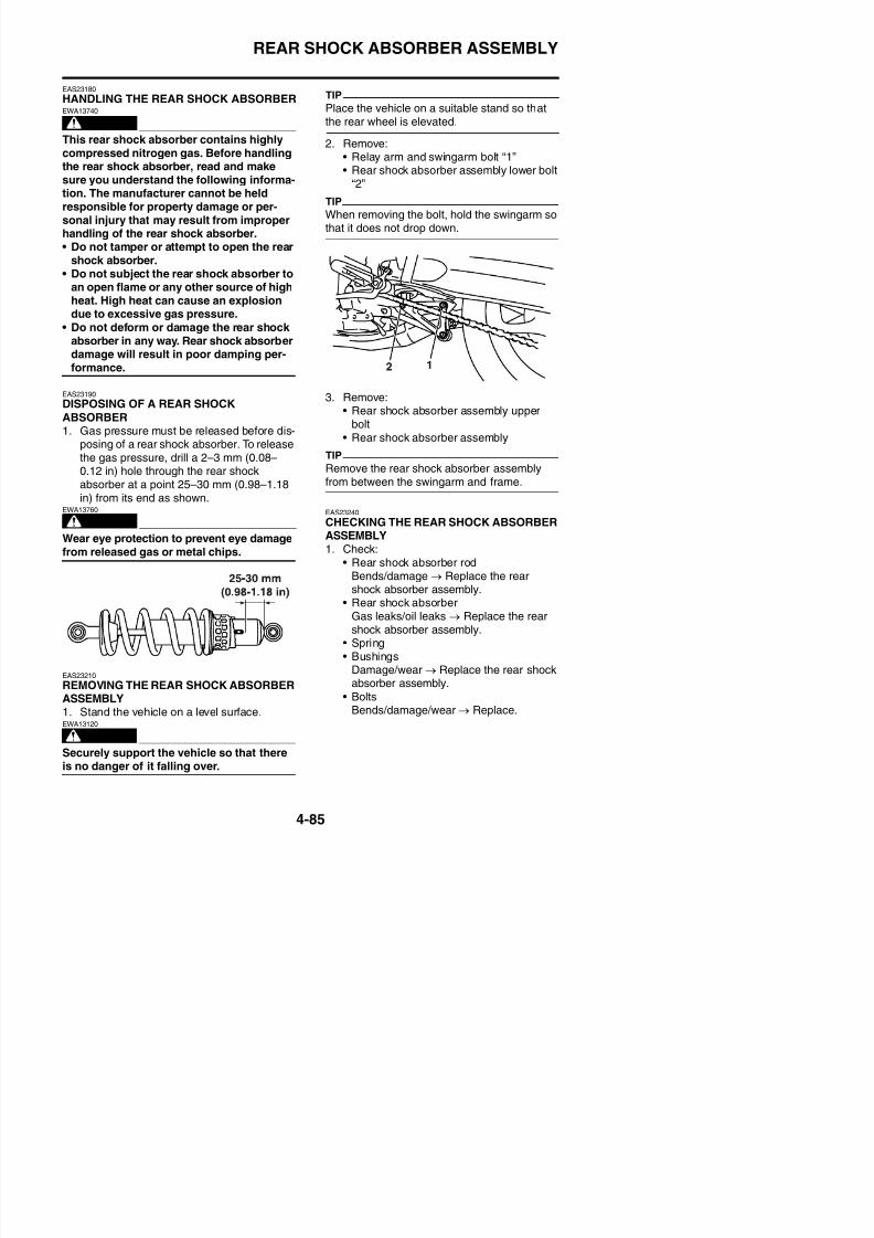
8/21/2019 Fz8 - Service Manual
http://slidepdf.com/reader/full/fz8-service-manual 252/609
EAS23190
DISPOSING OF A REAR SHOCK
ABSORBER1. Gas pressure must be released before dis-
posing of a rear shock absorber. To releasethe gas pressure, drill a 2–3 mm (0.08–0.12 in) hole through the rear shockabsorber at a point 25–30 mm (0.98–1.18
in) from its end as shown.
WARNING
EWA13760
Wear eye protection to prevent eye damagefrom released gas or metal chips.
3. Remove:• Rear shock absorber assembly upper
bolt• Rear shock absorber assembly
TIP
Remove the rear shock absorber assemblyfrom between the swingarm and frame.
EAS23240
CHECKING THE REAR SHOCK ABSORBERASSEMBLY1. Check:
• Rear shock absorber rodBends/damage → Replace the rearshock absorber assembly.
• Rear shock absorberG l k / il l k R l th
REAR SHOCK ABSORBER ASSEMBLY
EAS23261
CHECKING THE CONNECTING ARM ANDRELAY ARM1. Check:
• Connecting arm “1”• Relay arms “2”
Damage/wear → Replace.
2. Check:• Bearings• Oil seals
Damage/pitting → Replace.3. Check:
• Collars
3. Install:• Rear shock absorber assembly• Connecting arm “1”• Relay arms “2”
3. Frame
4. Swingarm
A. Left side
B. Right side
Frame and connecting armclearance “a”
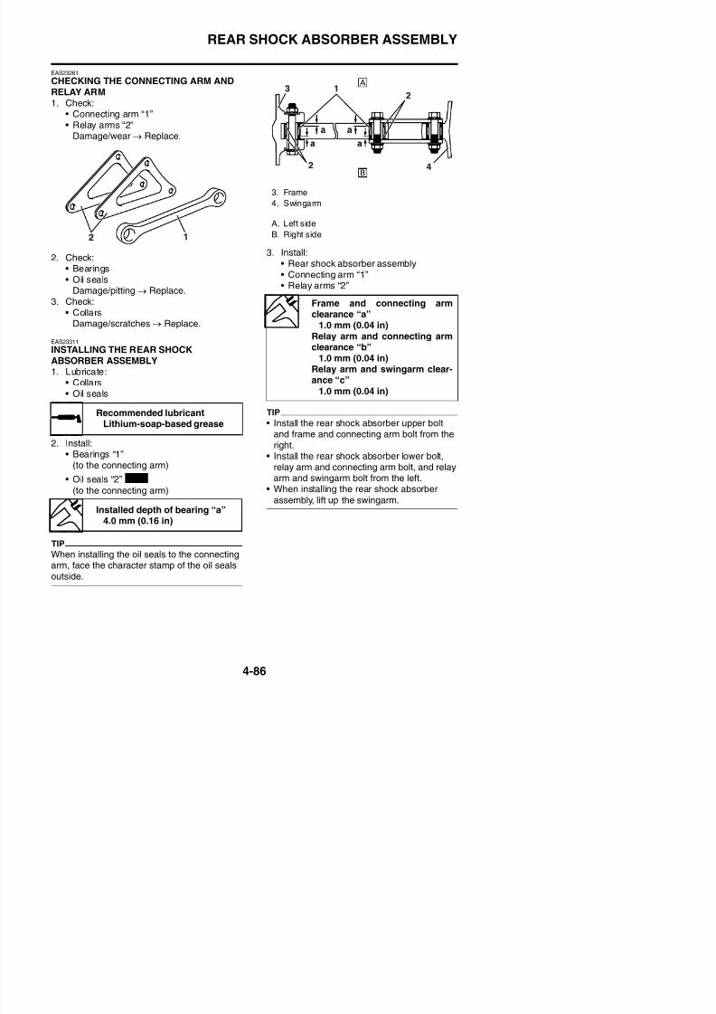
8/21/2019 Fz8 - Service Manual
http://slidepdf.com/reader/full/fz8-service-manual 253/609
Damage/scratches → Replace.
EAS23311
INSTALLING THE REAR SHOCKABSORBER ASSEMBLY1. Lubricate:
• Collars• Oil seals
2. Install:• Bearings “1”
(to the connecting arm)
• Oil seals “2”
(to the connecting arm)
TIP
• Install the rear shock absorber upper boltand frame and connecting arm bolt from theright.
• Install the rear shock absorber lower bolt,relay arm and connecting arm bolt, and relayarm and swingarm bolt from the left.
• When installing the rear shock absorber
assembly lift up the swingarm
Recommended lubricantLithium-soap-based grease
New
1.0 mm (0.04 in)Relay arm and connecting armclearance “b”
1.0 mm (0.04 in)Relay arm and swingarm clear-ance “c”
1.0 mm (0.04 in)
REAR SHOCK ABSORBER ASSEMBLY
4. Tighten:• Rear shock absorber assembly upper nut• Rear shock absorber assembly lower nut• Frame and connecting arm nut• Relay arm and swingarm nut• Relay arm and connecting arm nut
3. Frame
4. Swingarm
A. Left side
B. Right side
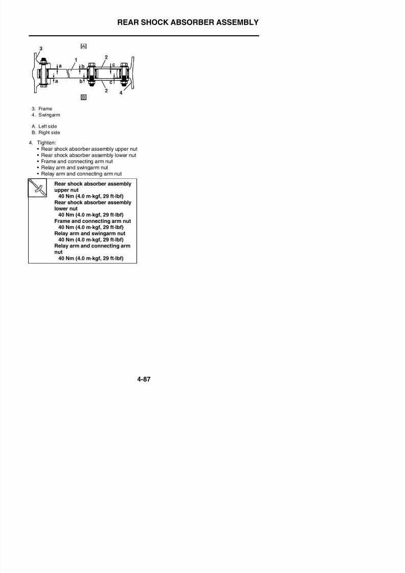
8/21/2019 Fz8 - Service Manual
http://slidepdf.com/reader/full/fz8-service-manual 254/609
Rear shock absorber assemblyupper nut
40 Nm (4.0 m·kgf, 29 ft·lbf)Rear shock absorber assemblylower nut
40 Nm (4.0 m·kgf, 29 ft·lbf)
Frame and connecting arm nut40 Nm (4.0 m·kgf, 29 ft·lbf)
Relay arm and swingarm nut40 Nm (4.0 m·kgf, 29 ft·lbf)
Relay arm and connecting armnut
40 Nm (4.0 m·kgf, 29 ft·lbf)
SWINGARM
EAS23330
SWINGARM
Removing the swingarm
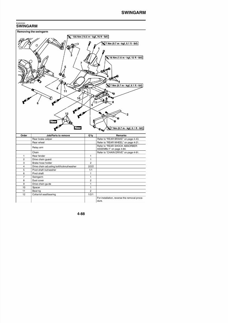
8/21/2019 Fz8 - Service Manual
http://slidepdf.com/reader/full/fz8-service-manual 255/609
Order Job/Parts to remove Q’ty Remarks
Rear brake caliper Refer to “REAR BRAKE” on page 4-43.
Rear wheel Refer to “REAR WHEEL” on page 4-21.
Relay armRefer to “REAR SHOCK ABSORBER
ASSEMBLY” on page 4-84.
Chain Refer to “CHAIN DRIVE” on page 4-91.
1 Rear fender 1
2 Drive chain guard 1
SWINGARM
EAS23350
REMOVING THE SWINGARM1. Stand the vehicle on a level surface.
WARNING
EWA13120
Securely support the vehicle so that thereis no danger of it falling over.
TIP
Place the vehicle on a suitable stand so thatthe rear wheel is elevated.
2. Remove:
• Relay arm and swingarm bolt “1”• Rear shock absorber assembly lower bolt
“2”
TIP
When removing the bolt, hold the swingarm sothat it does not drop down.
4. Remove:• Drive chain
Refer to “REMOVING THE DRIVECHAIN” on page 4-92.• Swingarm
EAS23361
CHECKING THE SWINGARM1. Check:
• SwingarmBends/cracks/damage → Replace.
2 Ch k
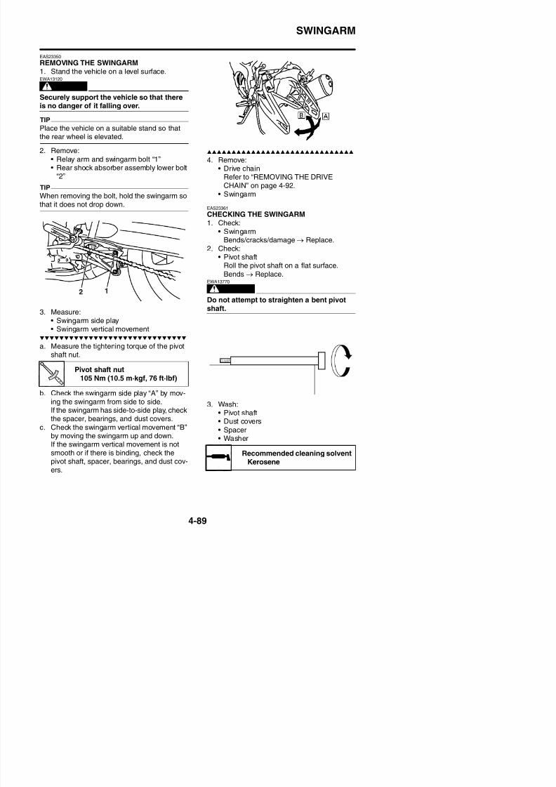
8/21/2019 Fz8 - Service Manual
http://slidepdf.com/reader/full/fz8-service-manual 256/609
3. Measure:
• Swingarm side play• Swingarm vertical movement
a. Measure the tightening torque of the pivotshaft nut.
2. Check:• Pivot shaft
Roll the pivot shaft on a flat surface.
Bends → Replace.
WARNING
EWA13770
Do not attempt to straighten a bent pivotshaft.
Pivot shaft nut105 Nm (10.5 m·kgf, 76 ft·lbf)
SWINGARM
4. Check:• Dust covers “1”• Spacer “2”• Oil seals “3”
Damage/wear → Replace.• Collar “4”
Damage/scratches→
Replace.• Bearings “5”Damage/pitting → Replace.
EAS23380
INSTALLING THE SWINGARM1. Lubricate:
S
3. Install:
• Swingarm
A. Left side
B. Right side
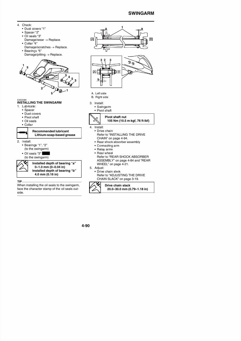
8/21/2019 Fz8 - Service Manual
http://slidepdf.com/reader/full/fz8-service-manual 257/609
• Spacer• Dust covers• Pivot shaft• Oil seals• Collar
2. Install:• Bearings “1”, “2”
(to the swingarm)
• Oil seals “3”
(to the swingarm)
• Swingarm• Pivot shaft
4. Install:• Drive chain
Refer to “INSTALLING THE DRIVE
CHAIN” on page 4-94.• Rear shock absorber assembly• Connecting arm• Relay arms• Rear wheel
Refer to “REAR SHOCK ABSORBERASSEMBLY” on page 4-84 and “REARWHEEL” on page 4-21.
5 Adjust:
Recommended lubricantLithium-soap-based grease
Installed depth of bearing “a”
0–1 0 mm (0–0 04 in)
New
Pivot shaft nut105 Nm (10.5 m·kgf, 76 ft·lbf)
CHAIN DRIVE
EAS23400
CHAIN DRIVE
Removing the drive chain
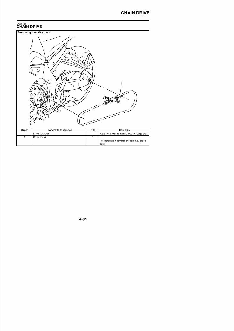
8/21/2019 Fz8 - Service Manual
http://slidepdf.com/reader/full/fz8-service-manual 258/609
Order Job/Parts to remove Q’ty Remarks
Drive sprocket Refer to “ENGINE REMOVAL” on page 5-3.1 Drive chain 1
For installation, reverse the removal proce-
dure.
CHAIN DRIVE
EAS23410
REMOVING THE DRIVE CHAIN1. Stand the vehicle on a level surface.
WARNING
EWA13120
Securely support the vehicle so that thereis no danger of it falling over.
TIP
Place the vehicle on a suitable stand so thatthe rear wheel is elevated.
2. Remove:
• Drive chain
TIP
Cut the drive chain with the drive chain cut &rivet tool. (Use goods on the market)
EAS23441
CHECKING THE DRIVE CHAIN1. Measure:
• 15-link section “a” of the drive chainOut of specification → Replace the drive
chain
2 Check:
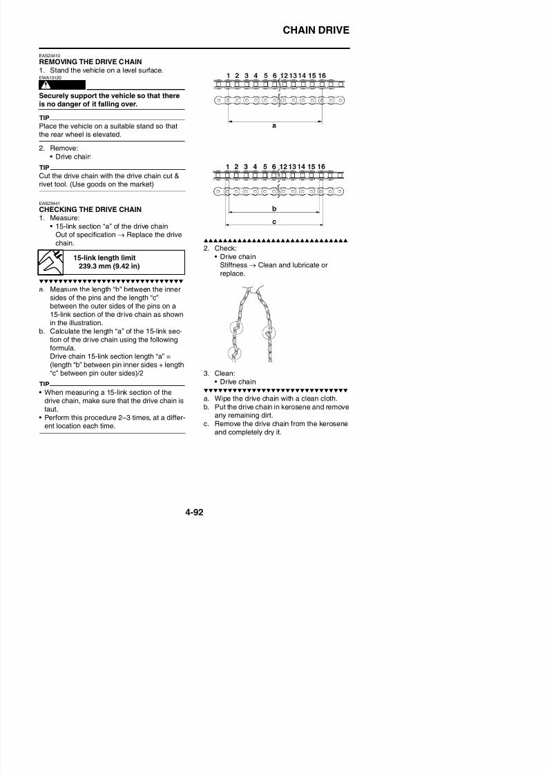
8/21/2019 Fz8 - Service Manual
http://slidepdf.com/reader/full/fz8-service-manual 259/609
chain.
a. Measure the length “b” between the innersides of the pins and the length “c”between the outer sides of the pins on a
15-link section of the drive chain as shownin the illustration.
b. Calculate the length “a” of the 15-link sec-tion of the drive chain using the followingformula.Drive chain 15-link section length “a” =(length “b” between pin inner sides + length“c” between pin outer sides)/2
TIP
2. Check:• Drive chain
Stiffness → Clean and lubricate orreplace.
3. Clean:
• Drive chain
15-link length limit239.3 mm (9.42 in)
CHAIN DRIVE
ECA39P1403
• This vehicle has a drive chain with smallrubber O-rings “1” between the drivechain side plates. Never use high-pres-sure water or air, steam, gasoline, certain
solvents (e.g., benzine), or a coarse brushto clean the drive chain. High-pressure
methods could force dirt or water into thedrive chain’s internals, and solvents willdeteriorate the O-rings. A coarse brushcan also damage the O-rings. Therefore,use only kerosene to clean the drivechain.
• Do not soak the drive chain in kerosenefor more than ten minutes, otherwise theO-rings can be damaged.
5. Lubricate:• Drive chain
EAS23460
CHECKING THE DRIVE SPROCKET1. Check:
• Drive sprocketMore than 1/4 tooth “a” wear → Replace
the drive chain sprockets as a set.Bent teeth → Replace the drive chain
Recommended lubricant
Chain lubricant suitable for O-ring chains
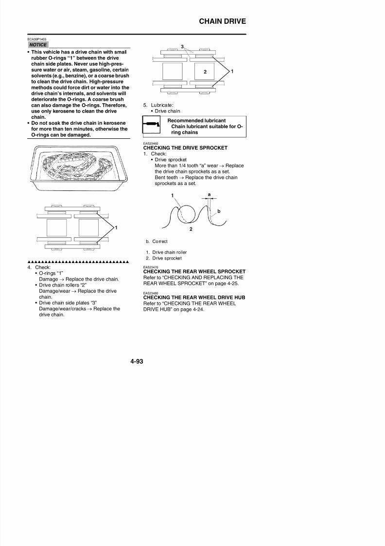
8/21/2019 Fz8 - Service Manual
http://slidepdf.com/reader/full/fz8-service-manual 260/609
4 Check:
the drive chain sprockets as a set.Bent teeth → Replace the drive chainsprockets as a set.
EAS23470CHECKING THE REAR WHEEL SPROCKET
b. Correct
1. Drive chain roller
2. Drive sprocket
CHAIN DRIVE
EAS39P1403
INSTALLING THE DRIVE CHAIN1. Install:
• Drive chain
TIP
Install the drive chain joint with the drive chaincut & rivet tool. (Use goods on the market)
a. When press fitting the connecting plate “1”,make sure the space “a” between the endof the connecting pin “2” and the connect-ing plate is 1.2–1.4 mm (0.05–0.06 in).
b. After riveting, make sure the diameter
between the edges “b” of the connectingpin “2” is 5 5 5 8 mm (0 22 0 23 in)
3. Install:• Drive sprocket• Washer
• Drive sprocket nut
Refer to “ENGINE REMOVAL” on page 5-3.
4. Adjust:• Drive chain slack
Refer to “ADJUSTING THE DRIVECHAIN SLACK” on page 3-19.
ECA13550
A drive chain that is too tight will overloadthe engine and other vital parts, and onethat is too loose can skip and damage theswingarm or cause an accident Therefore
Drive sprocket nut85 Nm (8.5 m·kgf, 61 ft·lbf)LOCTITE®
Drive chain slack 20.0–30.0 mm (0.79–1.18 in)
New
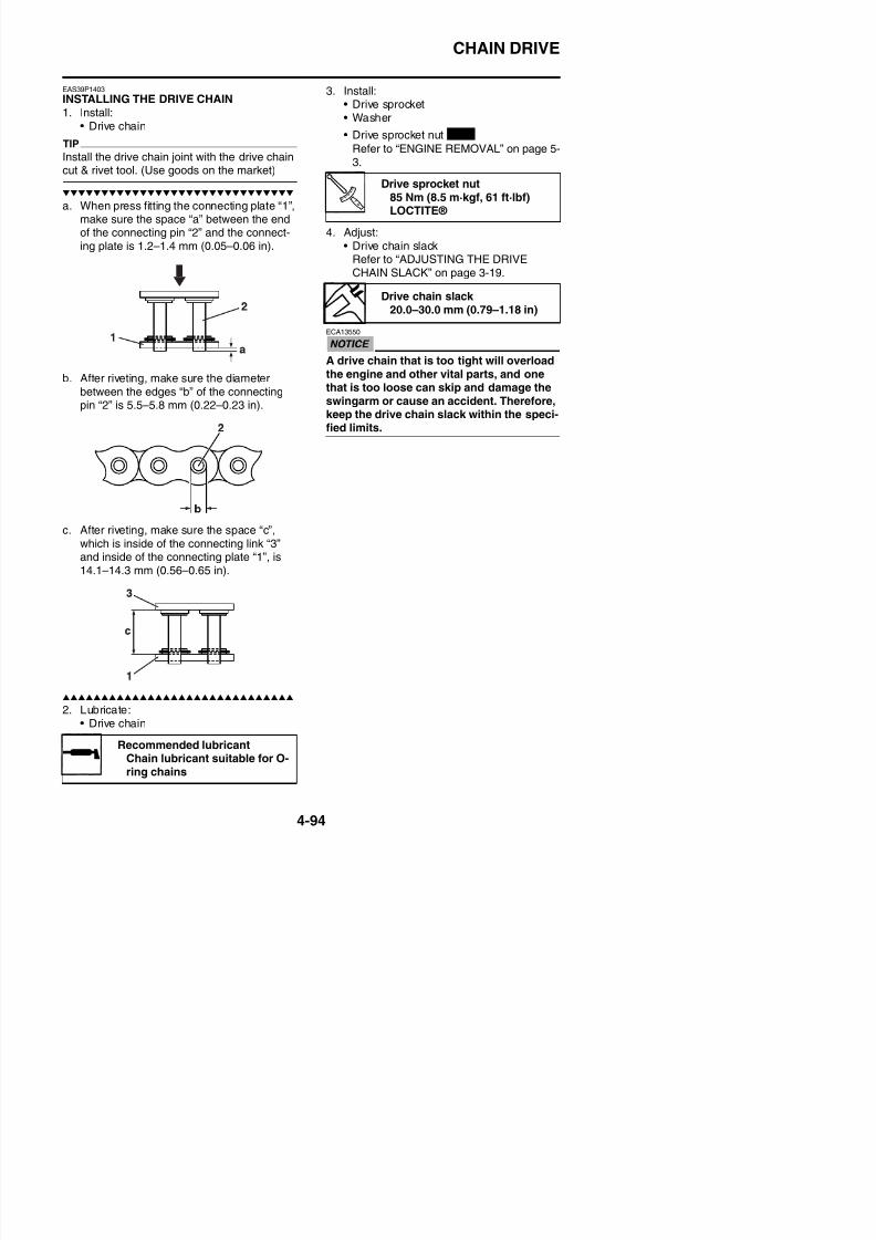
8/21/2019 Fz8 - Service Manual
http://slidepdf.com/reader/full/fz8-service-manual 261/609
g gpin “2” is 5.5–5.8 mm (0.22–0.23 in).
c. After riveting, make sure the space “c”,which is inside of the connecting link “3”and inside of the connecting plate “1”, is14.1–14.3 mm (0.56–0.65 in).
swingarm or cause an accident. Therefore,keep the drive chain slack within the speci-fied limits.
CHAIN DRIVE

8/21/2019 Fz8 - Service Manual
http://slidepdf.com/reader/full/fz8-service-manual 262/609
ENGINE
ENGINE INSPECTION..................................................................................5-1MEASURING THE COMPRESSION PRESSURE ................................. 5-1
ENGINE REMOVAL ......................................................................................5-3INSTALLING THE ENGINE .................................................................... 5-8
INSTALLING THE DRIVE SPROCKET ................................................5-10
CAMSHAFTS..............................................................................................5-11REMOVING THE CAMSHAFTS...........................................................5-13CHECKING THE CAMSHAFTS ...........................................................5-14CHECKING THE TIMING CHAIN AND CAMSHAFT SPROCKET.......5-15CHECKING THE TIMING CHAIN GUIDES ..........................................5-15CHECKING THE TIMING CHAIN TENSIONER...................................5-16INSTALLING THE CAMSHAFTS..........................................................5-17
CYLINDER HEAD.......................................................................................5-20REMOVING THE CYLINDER HEAD ....................................................5-21CHECKING THE CYLINDER HEAD ....................................................5-21
INSTALLING THE CYLINDER HEAD...................................................5-21
8/21/2019 Fz8 - Service Manual
http://slidepdf.com/reader/full/fz8-service-manual 263/609
5VALVES AND VALVE SPRINGS ................................................................5-23
REMOVING THE VALVES....................................................................5-25CHECKING THE VALVES AND VALVE GUIDES ................................. 5-26CHECKING THE VALVE SEATS ..........................................................5-28CHECKING THE VALVE SPRINGS...................................................... 5-29CHECKING THE VALVE LIFTERS.......................................................5-30INSTALLING THE VALVES................................................................... 5-30
GENERATOR..............................................................................................5-32REMOVING THE GENERATOR...........................................................5-34INSTALLING THE GENERATOR..........................................................5-34
STARTER CLUTCH ....................................................................................5-36REMOVING THE STARTER CLUTCH 5 37
ELECTRIC STARTER.................................................................................5-41CHECKING THE STARTER MOTOR ...................................................5-43ASSEMBLING THE STARTER MOTOR...............................................5-44INSTALLING THE STARTER MOTOR..................................................5-44
CLUTCH......................................................................................................5-45
REMOVING THE CLUTCH...................................................................5-49CHECKING THE FRICTION PLATES ..................................................5-50
CHECKING THE CLUTCH PLATES.....................................................5-50CHECKING THE CLUTCH SPRINGS..................................................5-51CHECKING THE CLUTCH HOUSING .................................................5-51CHECKING THE CLUTCH BOSS ........................................................5-51CHECKING THE PRESSURE PLATE..................................................5-51CHECKING THE PULL LEVER SHAFT AND PULL ROD....................5-52
INSTALLING THE CLUTCH..................................................................5-52
SHIFT SHAFT .............................................................................................5-55CHECKING THE SHIFT SHAFT ..........................................................5-56CHECKING THE STOPPER LEVER....................................................5-56
INSTALLING THE SHIFT SHAFT.........................................................5-56
OIL PUMP ...................................................................................................5-57REMOVING THE OIL PAN 5 60
8/21/2019 Fz8 - Service Manual
http://slidepdf.com/reader/full/fz8-service-manual 264/609
REMOVING THE OIL PAN ................................................................... 5-60CHECKING THE SPROCKET AND CHAIN .........................................5-60CHECKING THE OIL PUMP ................................................................ 5-60CHECKING THE RELIEF VALVE .........................................................5-61CHECKING THE OIL DELIVERY PIPES..............................................5-61CHECKING THE OIL STRAINER.........................................................5-61ASSEMBLING THE OIL PUMP ............................................................5-62
INSTALLING THE OIL/WATER PUMP..................................................5-62INSTALLING THE OIL PAN .................................................................. 5-63
CRANKCASE .............................................................................................5-65DISASSEMBLING THE CRANKCASE.................................................5-67CHECKING THE CRANKCASE ...........................................................5-67ASSEMBLING THE CRANKCASE.......................................................5-67
CRANKSHAFT ...........................................................................................5-80REMOVING THE CRANKSHAFT ASSEMBLY.....................................5-81CHECKING THE OIL NOZZLES ..........................................................5-81CHECKING THE CRANKSHAFT .........................................................5-81INSTALLING THE CRANKSHAFT........................................................5-83
TRANSMISSION.........................................................................................5-84REMOVING THE TRANSMISSION......................................................5-89
CHECKING THE SHIFT FORKS..........................................................5-89CHECKING THE SHIFT DRUM ASSEMBLY........................................5-90CHECKING THE TRANSMISSION ......................................................5-90ASSEMBLING THE MAIN AXLE AND DRIVE AXLE ........................... 5-91INSTALLING THE TRANSMISSION.....................................................5-91
8/21/2019 Fz8 - Service Manual
http://slidepdf.com/reader/full/fz8-service-manual 265/609
ENGINE INSPECTION
EAS14B1052
ENGINE INSPECTION
EAS20710
MEASURING THE COMPRESSION PRES-SUREThe following procedure applies to all of the
cylinders.TIP
Insufficient compression pressure will result ina loss of performance.
1. Measure:• Valve clearance
Out of specification → Adjust.
Refer to “ADJUSTING THE VALVECLEARANCE” on page 3-5.2. Start the engine, warm it up for several
minutes, and then turn it off.
3. Remove:• Ignition coils• Spark plugs
ECA13340
Before removing the spark plugs, use com-
5. Measure:• Compression pressure
Out of specification → Refer to steps (c)and (d).
a. Set the main switch to “ON”.b. With the throttle wide open, crank the
engine until the reading on the compres-sion gauge stabilizes.
WARNING
EWA39P1501
To prevent sparking the plug, remove all
ignition coil couplers and fuel injector cou-plers before cranking the engine.
Standard compression pres-sure (at sea level)
1480 kPa/350 r/min (14.8 kgf/ cm²/350 r/min, 210.5 psi/350 r/ min)
Minimum–Maximum1290–1660 kPa/350 r/min(12.9–16.6 kgf/cm²/350 r/min,183.5–236.1 psi/350 r/min)
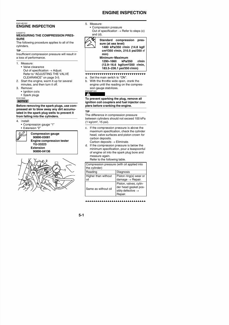
8/21/2019 Fz8 - Service Manual
http://slidepdf.com/reader/full/fz8-service-manual 266/609
pressed air to blow away any dirt accumu-
lated in the spark plug wells to prevent itfrom falling into the cylinders.
4. Install:• Compression gauge “1”• Extension “2”
TIP
The difference in compression pressurebetween cylinders should not exceed 100 kPa(1 kg/cm², 15 psi).
c. If the compression pressure is above the
maximum specification, check the cylinderhead, valve surfaces and piston crown forcarbon deposits.Carbon deposits → Eliminate.
d. If the compression pressure is below theminimum specification, pour a teaspoonfulof engine oil into the spark plug bore andmeasure again.
Refer to the following table
Compression gauge
90890-03081Engine compression tester
YU-33223Extension
90890-04136
ENGINE INSPECTION
6. Install:• Spark plug
7. Install:
• Ignition coils
Spark plug13 Nm (1.3 m·kgf, 9.4 ft·lbf)
8/21/2019 Fz8 - Service Manual
http://slidepdf.com/reader/full/fz8-service-manual 267/609
ENGINE REMOVAL
EAS23711
ENGINE REMOVAL
Removing the drive sprocket
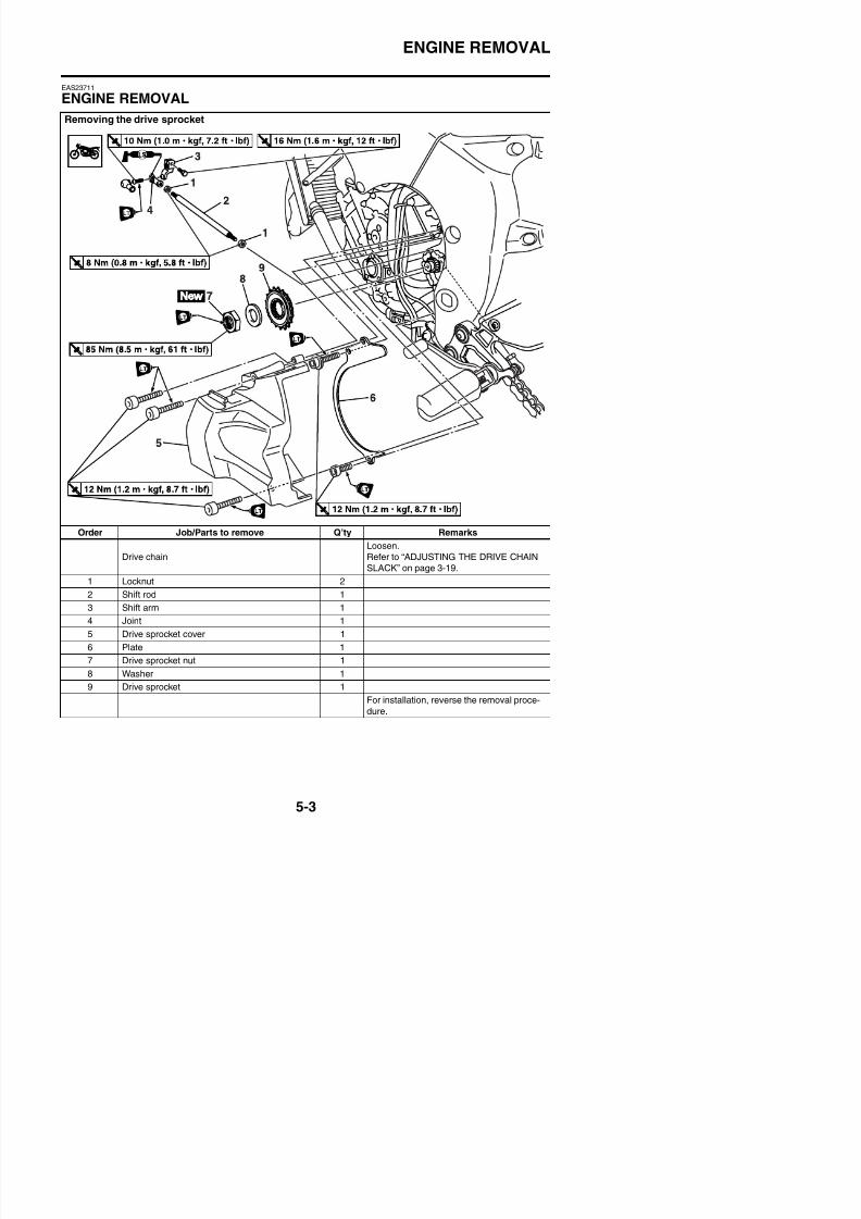
8/21/2019 Fz8 - Service Manual
http://slidepdf.com/reader/full/fz8-service-manual 268/609
Order Job/Parts to remove Q’ty Remarks
Drive chain
Loosen.
Refer to “ADJUSTING THE DRIVE CHAIN
SLACK” on page 3-19.
1 Locknut 2
2 Shift rod 1
S f
ENGINE REMOVAL
Removing the muffler and exhaust pipe
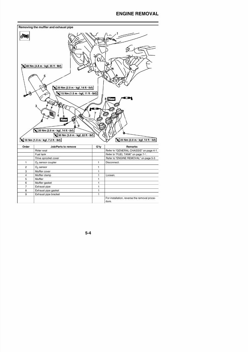
8/21/2019 Fz8 - Service Manual
http://slidepdf.com/reader/full/fz8-service-manual 269/609
Order Job/Parts to remove Q’ty Remarks
Rider seat Refer to “GENERAL CHASSIS” on page 4-1.
Fuel tank Refer to “FUEL TANK” on page 7-1.
Drive sprocket cover Refer to “ENGINE REMOVAL” on page 5-3.
1 O2 sensor coupler 1 Disconnect.
2 O2 sensor 1
3 Muffler cover 1
4 M ffl l 1 L
ENGINE REMOVAL
Disconnecting the leads and hoses
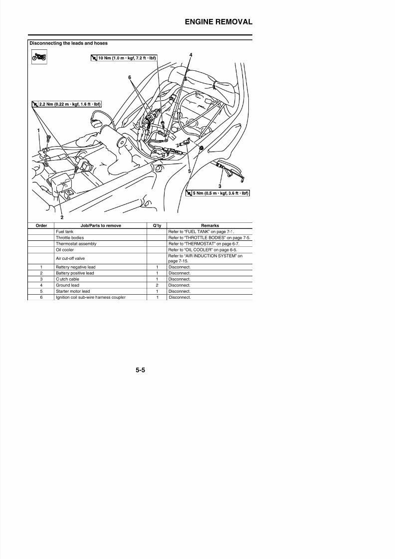
8/21/2019 Fz8 - Service Manual
http://slidepdf.com/reader/full/fz8-service-manual 270/609
Order Job/Parts to remove Q’ty RemarksFuel tank Refer to “FUEL TANK” on page 7-1.
Throttle bodies Refer to “THROTTLE BODIES” on page 7-5.
Thermostat assembly Refer to “THERMOSTAT” on page 6-7.
Oil cooler Refer to “OIL COOLER” on page 6-5.
Air cut-off valveRefer to “AIR INDUCTION SYSTEM” on
page 7-15.
1 Battery negative lead 1 Disconnect.
2 Battery positive lead 1 Disconnect.
ENGINE REMOVAL
Disconnecting the leads and hoses
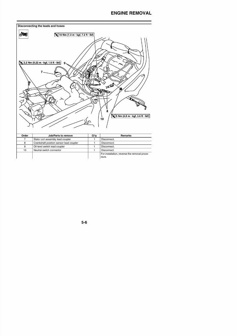
8/21/2019 Fz8 - Service Manual
http://slidepdf.com/reader/full/fz8-service-manual 271/609
Order Job/Parts to remove Q’ty Remarks7 Stator coil assembly lead coupler 1 Disconnect.
8 Crankshaft position sensor lead coupler 1 Disconnect.
9 Oil level switch lead coupler 1 Disconnect.
10 Neutral switch connector 1 Disconnect.
For installation, reverse the removal proce-
dure.
ENGINE REMOVAL
Removing the engine
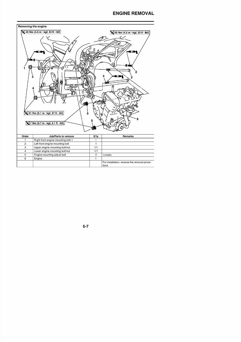
8/21/2019 Fz8 - Service Manual
http://slidepdf.com/reader/full/fz8-service-manual 272/609
Order Job/Parts to remove Q’ty Remarks
1 Right front engine mounting bolt 1 1
2 Left front engine mounting bolt 1
3 Upper engine mounting bolt/nut 1/1
4 Lower engine mounting bolt/nut 1/1
5 Engine mounting adjust bolt 2 Loosen.
6 Engine 1
For installation, reverse the removal proce-
dure.
ENGINE REMOVAL
EAS23720
INSTALLING THE ENGINE1. Install:
• Right front engine mounting bolt 2 “1”Refer to “CYLINDER HEAD” on page 5-20.
2. Tighten:• Right front engine mounting bolt 2
3 Install:
6. Install:• Left front engine mounting bolt “1”
(temporarily tighten)• Right front engine mounting bolt 1 “2”
(temporarily tighten)
Right front engine mountingbolt 2
50 Nm (5.0 m·kgf, 36 ft·lbf)
LOCTITE®
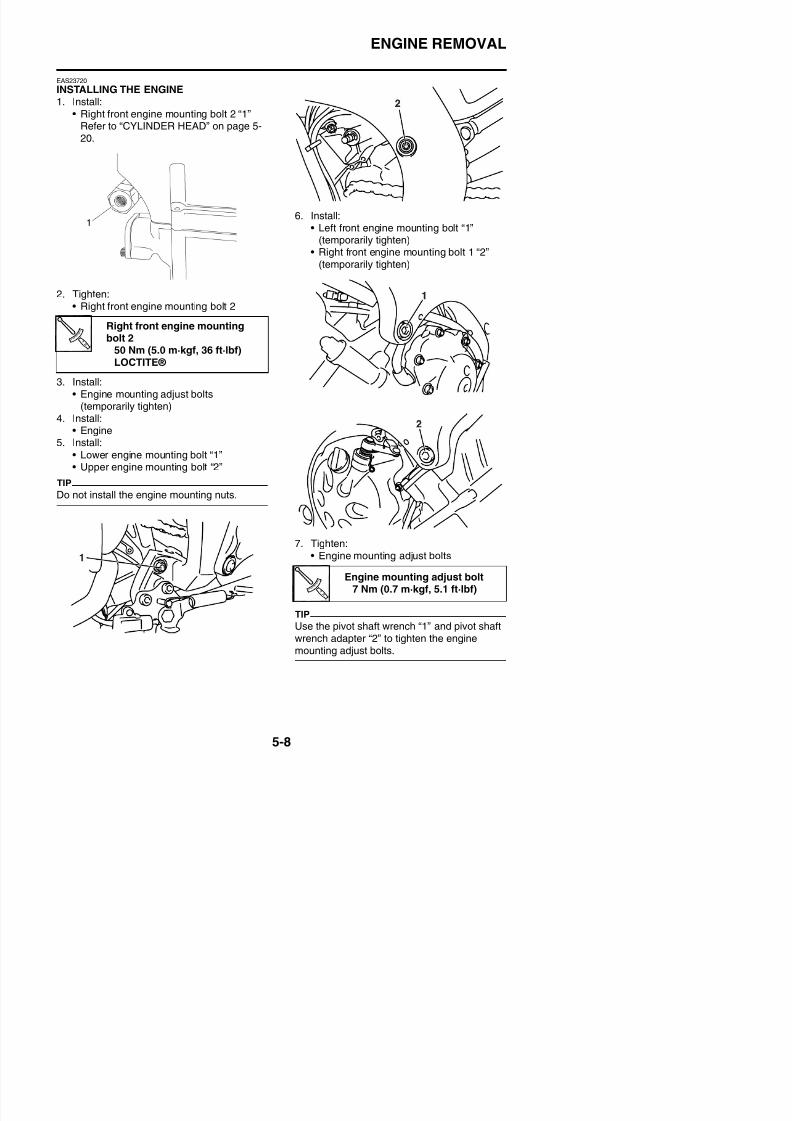
8/21/2019 Fz8 - Service Manual
http://slidepdf.com/reader/full/fz8-service-manual 273/609
3. Install:• Engine mounting adjust bolts
(temporarily tighten)4. Install:
• Engine5. Install:
• Lower engine mounting bolt “1”• Upper engine mounting bolt “2”
TIP
Do not install the engine mounting nuts.
7. Tighten:
E i ti dj t b lt
ENGINE REMOVAL
9. Tighten:• Left front engine mounting bolt “1”• Right front engine mounting bolt 1 “2”
TIP
First tighten the left front engine mounting bolt
“1”, and then tighten the right front enginemounting bolt 1 “2”.
Pivot shaft wrench90890-01518
Frame spanner socketYM-01518
Pivot shaft wrench adapter90890-01476
Left front engine mounting bolt45 Nm (4.5 m·kgf, 33 ft·lbf)
Right front engine mountingbolt 1
45 Nm (4.5 m·kgf, 33 ft·lbf)
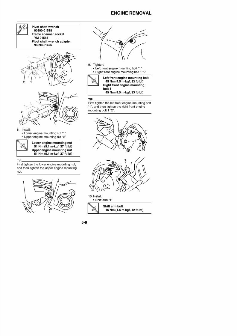
8/21/2019 Fz8 - Service Manual
http://slidepdf.com/reader/full/fz8-service-manual 274/609
8. Install:• Lower engine mounting nut “1”
• Upper engine mounting nut “2”
TIP
First tighten the lower engine mounting nut,
Lower engine mounting nut51 Nm (5.1 m·kgf, 37 ft·lbf)
Upper engine mounting nut51 Nm (5.1 m·kgf, 37 ft·lbf)
ENGINE REMOVAL
TIP
Align punch mark “a” of the shift arm “1” withalignment mark “b” of the crankcase.
EAS39P1501INSTALLING THE DRIVE SPROCKET1. Install:
• Drive sprocket• Washer
• Drive sprocket nut “1”
Drive sprocket nut
85 Nm (8.5 m·kgf, 61 ft·lbf)LOCTITE®
New
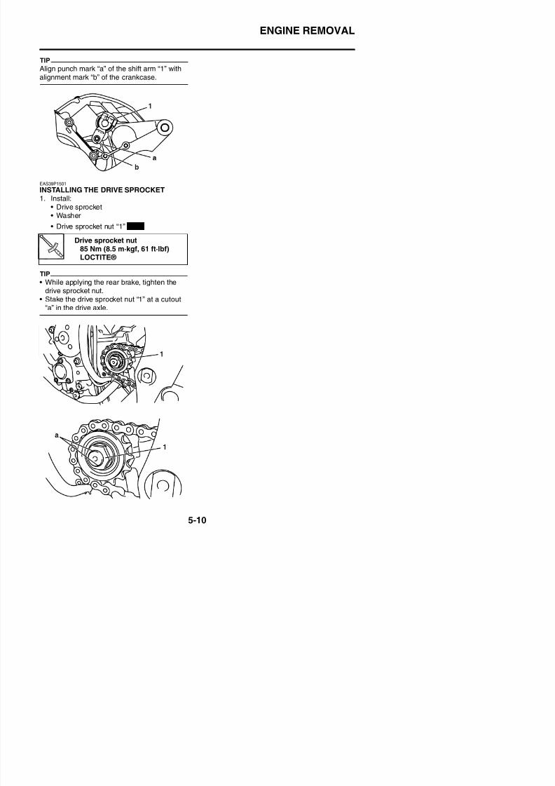
8/21/2019 Fz8 - Service Manual
http://slidepdf.com/reader/full/fz8-service-manual 275/609
TIP
• While applying the rear brake, tighten thedrive sprocket nut.
• Stake the drive sprocket nut “1” at a cutout“a” in the drive axle.
CAMSHAFTS
EAS23760
CAMSHAFTS
Removing the cylinder head cover
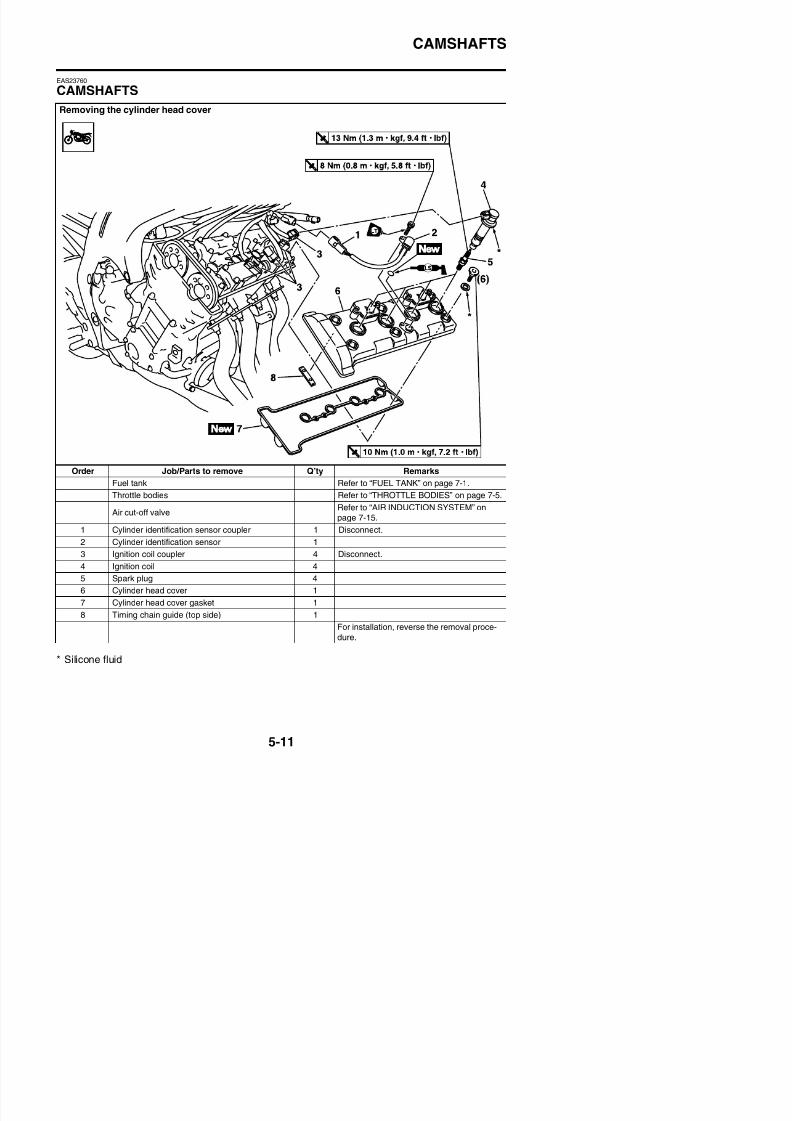
8/21/2019 Fz8 - Service Manual
http://slidepdf.com/reader/full/fz8-service-manual 276/609
Order Job/Parts to remove Q’ty Remarks
Fuel tank Refer to “FUEL TANK” on page 7-1.
Throttle bodies Refer to “THROTTLE BODIES” on page 7-5.
Air cut-off valveRefer to “AIR INDUCTION SYSTEM” on
page 7-15.
1 Cylinder identification sensor coupler 1 Disconnect.
2 Cylinder identification sensor 1
I i i il l Di
CAMSHAFTS
Removing the camshafts
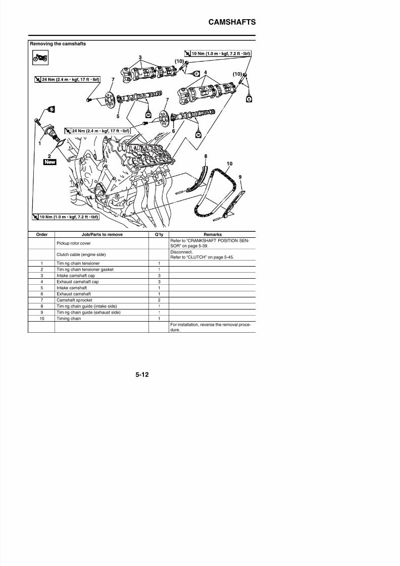
8/21/2019 Fz8 - Service Manual
http://slidepdf.com/reader/full/fz8-service-manual 277/609
Order Job/Parts to remove Q’ty Remarks
Pickup rotor coverRefer to “CRANKSHAFT POSITION SEN-
SOR” on page 5-39.
Clutch cable (engine side)Disconnect.
Refer to “CLUTCH” on page 5-45.
1 Timing chain tensioner 1
2 Timing chain tensioner gasket 1
3 Intake camshaft cap 3
CAMSHAFTS
EAS23810
REMOVING THE CAMSHAFTS1. Remove:
• Pickup rotor coverRefer to “CRANKSHAFT POSITIONSENSOR” on page 5-39.
2. Align:
• “T” mark “a” on the pickup rotor(with the crankcase mating surface “b”)
a. Turn the crankshaft clockwise.b. When piston #1 is at TDC on the compres-
sion stroke, align the “T” mark “a” on thepickup rotor with the crankcase mating sur-face “b”.
TIPTDC on the compression stroke can be foundwhen the camshaft lobes are turned away fromeach other.
camshaft cap bolts in stages and in a criss-cross pattern, working from the outside in.
5. Remove:• Intake camshaft “1”
• Exhaust camshaft “2”
TIP
To prevent the timing chain from falling into thecrankcase, fasten it with a wire “3”.
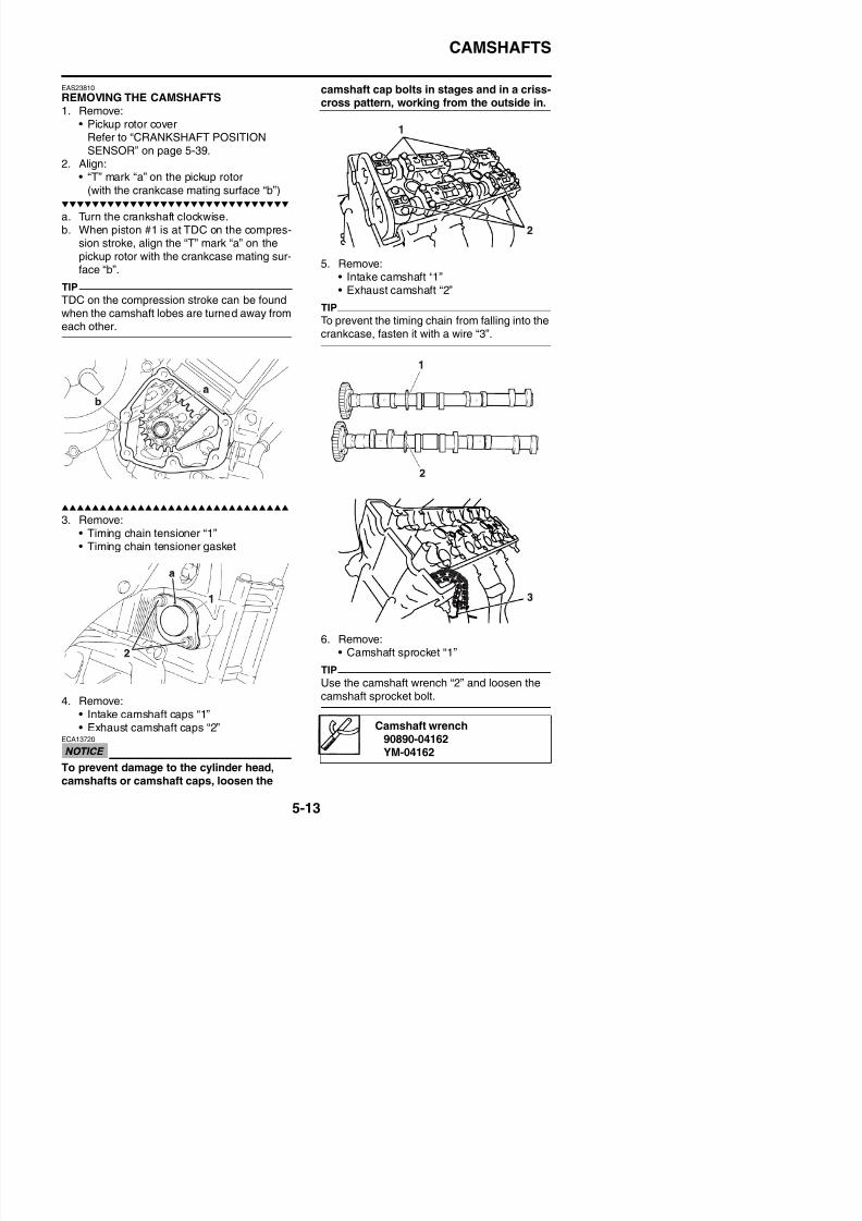
8/21/2019 Fz8 - Service Manual
http://slidepdf.com/reader/full/fz8-service-manual 278/609
3. Remove:• Timing chain tensioner “1”• Timing chain tensioner gasket
CAMSHAFTS
EAS23850
CHECKING THE CAMSHAFTS1. Check:
• Camshaft lobesBlue discoloration/pitting/scratches → Replace the camshaft.
2. Measure:• Camshaft lobe dimensions “a” and “b”
Out of specification → Replace the cam-shaft.
3. Measure:• Camshaft runout
Out of specification → Replace.
Camshaft lobe dimension limitIntake A
35.750–35.850 mm (1.4075–1.4114 in)
Limit
Camshaft runout limit0.030 mm (0.0012 in)
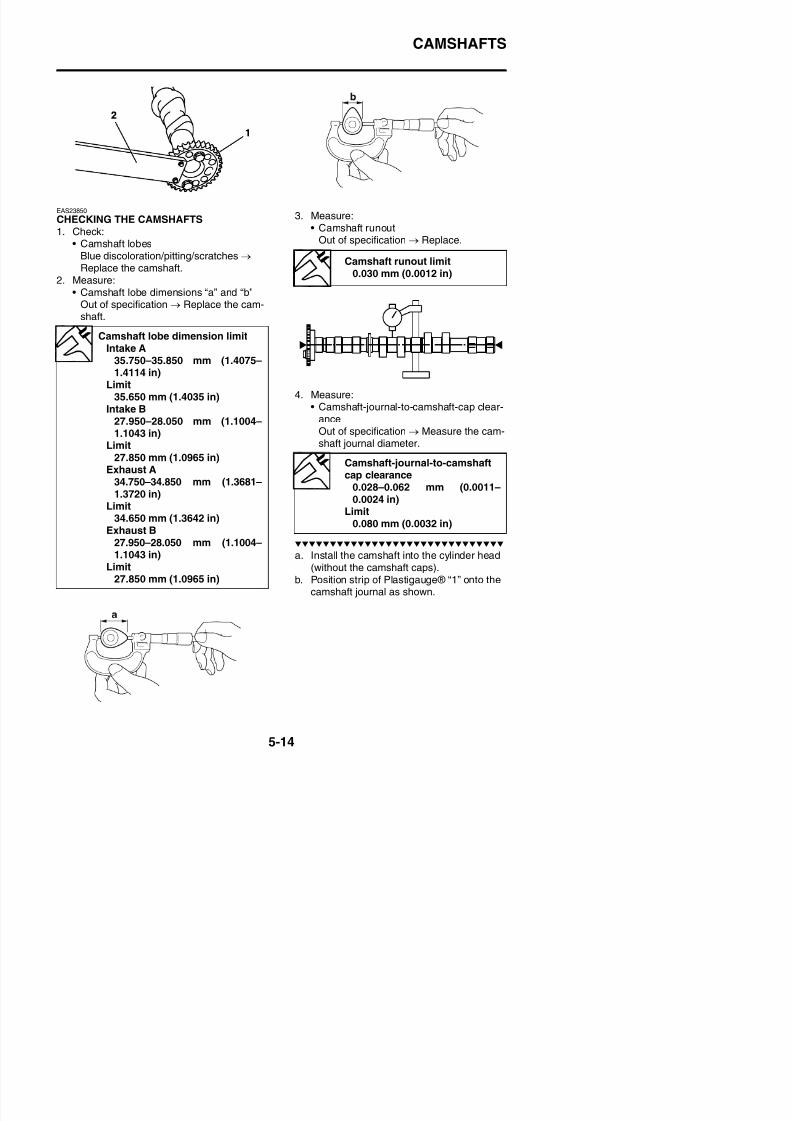
8/21/2019 Fz8 - Service Manual
http://slidepdf.com/reader/full/fz8-service-manual 279/609
4. Measure:• Camshaft-journal-to-camshaft-cap clear-
anceOut of specification → Measure the cam-shaft journal diameter.
35.650 mm (1.4035 in)Intake B
27.950–28.050 mm (1.1004–1.1043 in)
Limit
27.850 mm (1.0965 in)Exhaust A
34.750–34.850 mm (1.3681–1.3720 in)
Limit34.650 mm (1.3642 in)
Exhaust B27.950–28.050 mm (1.1004–
Camshaft-journal-to-camshaftcap clearance
0.028–0.062 mm (0.0011–0.0024 in)
Limit0.080 mm (0.0032 in)
CAMSHAFTS
c. Install the dowel pins and camshaft caps.
TIP
• Tighten the camshaft cap bolts in stages andin a crisscross pattern, working from theinner caps out.
• Do not turn the camshaft when measuringthe camshaft journal-to-camshaft cap clear-ance with the Plastigauge®.
d. Remove the camshaft caps and then mea-sure the width of the Plastigauge® “2”.
EAS23870
CHECKING THE TIMING CHAIN AND CAM-SHAFT SPROCKET1. Check:
• Timing chainDamage/stiffness → Replace the timingchain and camshaft and camshaftsprocket as a set.
2. Check:• Camshaft sprocket
More than 1/4 tooth wear “a” → Replacethe camshaft sprockets and the timing
chain as a set.
Camshaft cap bolt10 Nm (1.0 m·kgf, 7.2 ft·lbf)
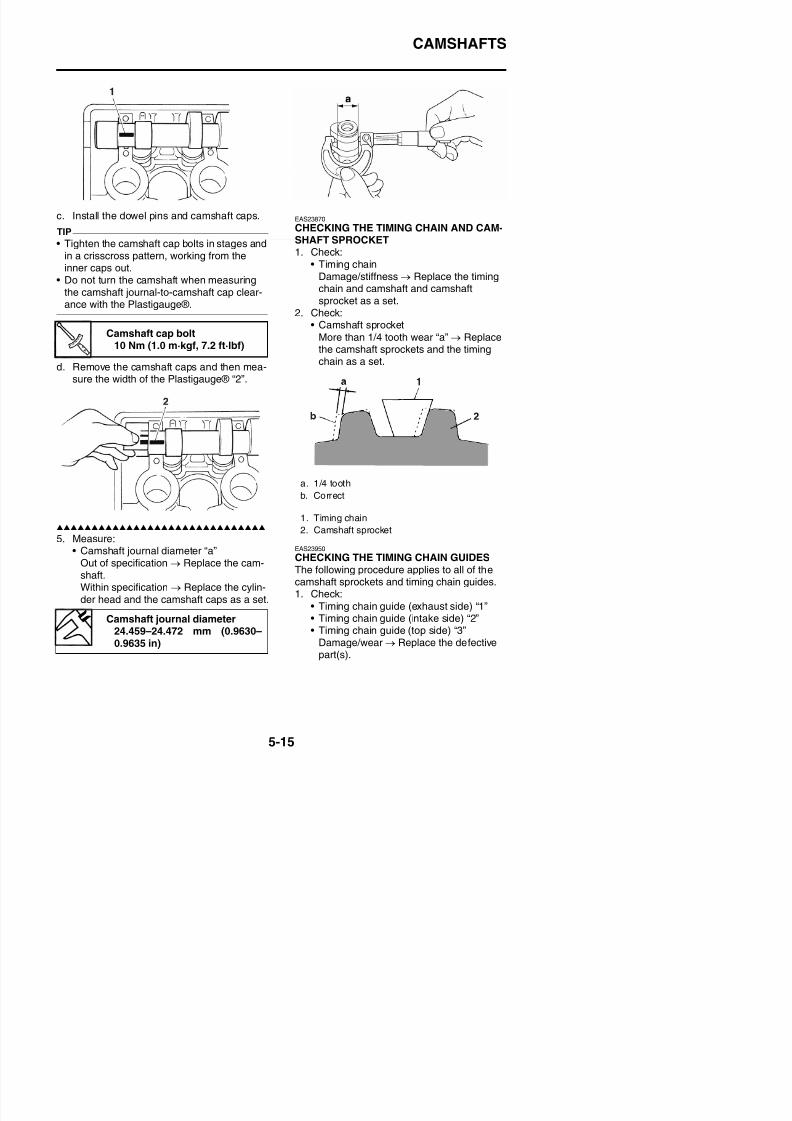
8/21/2019 Fz8 - Service Manual
http://slidepdf.com/reader/full/fz8-service-manual 280/609
5. Measure:EAS23950
a. 1/4 tooth
b. Correct
1. Timing chain
2. Camshaft sprocket
CAMSHAFTS
EAS23960
CHECKING THE TIMING CHAIN TEN-
SIONER1. Remove:
• Timing chain tensioner housing “1”
• Timing chain tensioner rod “2”• Timing chain tensioner spring “3”• Timing chain tensioner spring seat “4”
TIP
Squeeze the timing chain tensioner clip “5”,and then remove the timing chain tensionerspring and timing chain tensioner rod.
b. Squeeze the timing chain tensioner clip “2”,and then push the timing chain tensionerrod “3” into the timing chain tensioner hous-ing.
TIPDo not release the timing chain tensioner clipwhile pushing the rod into the housing, other-wise the rod may be ejected.
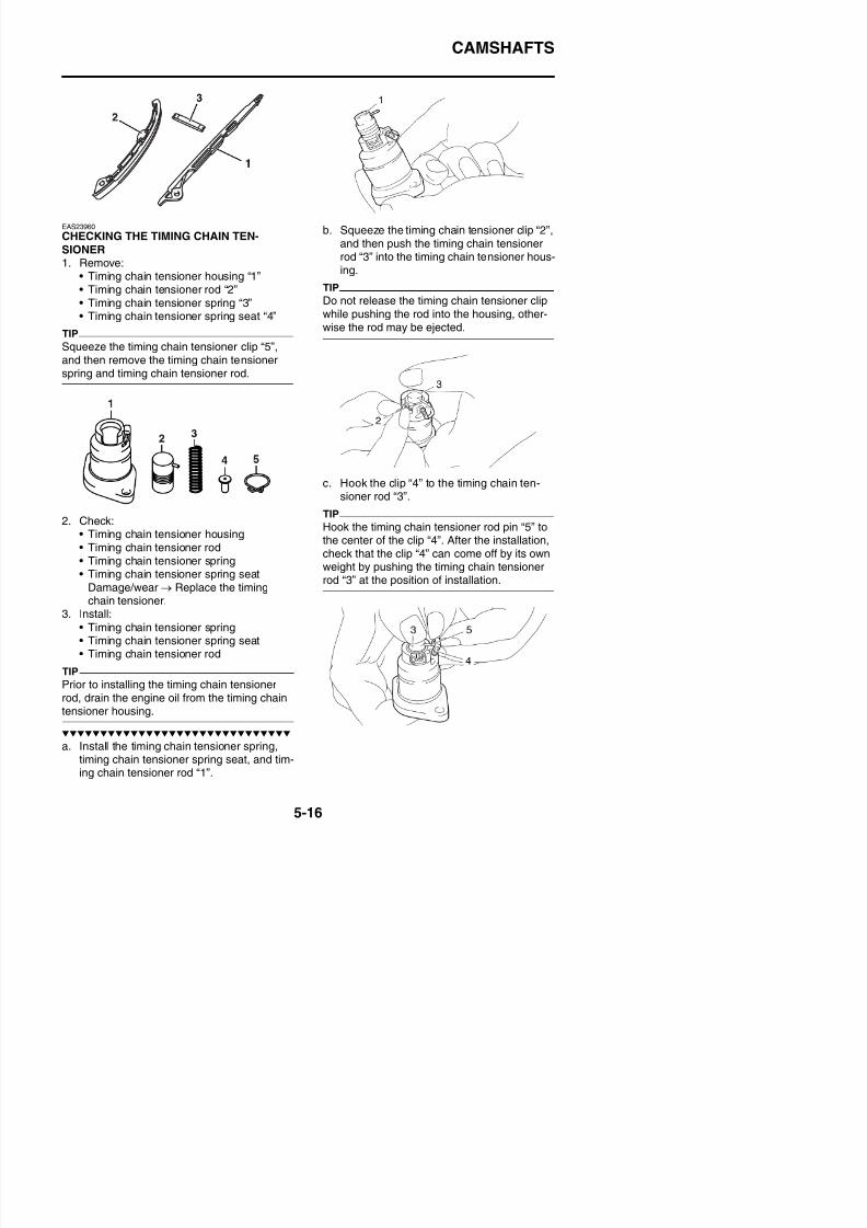
8/21/2019 Fz8 - Service Manual
http://slidepdf.com/reader/full/fz8-service-manual 281/609
2. Check:• Timing chain tensioner housing• Timing chain tensioner rod• Timing chain tensioner spring• Timing chain tensioner spring seat
Damage/wear → Replace the timingchain tensioner.
c. Hook the clip “4” to the timing chain ten-sioner rod “3”.
TIP
Hook the timing chain tensioner rod pin “5” tothe center of the clip “4”. After the installation,check that the clip “4” can come off by its ownweight by pushing the timing chain tensionerrod “3” at the position of installation.
CAMSHAFTS
EAS24000
INSTALLING THE CAMSHAFTS1. Align:
• “T” mark “a” on the pickup rotor(with the crankcase mating surface “b”)
a. Turn the crankshaft clockwise.b. When piston #1 is at TDC, align the “T”
mark “a” with the crankcase mating surface“b”.
3. Install:• Exhaust camshaft “1”• Intake camshaft “2”
Camshaft wrench90890-04162YM-04162
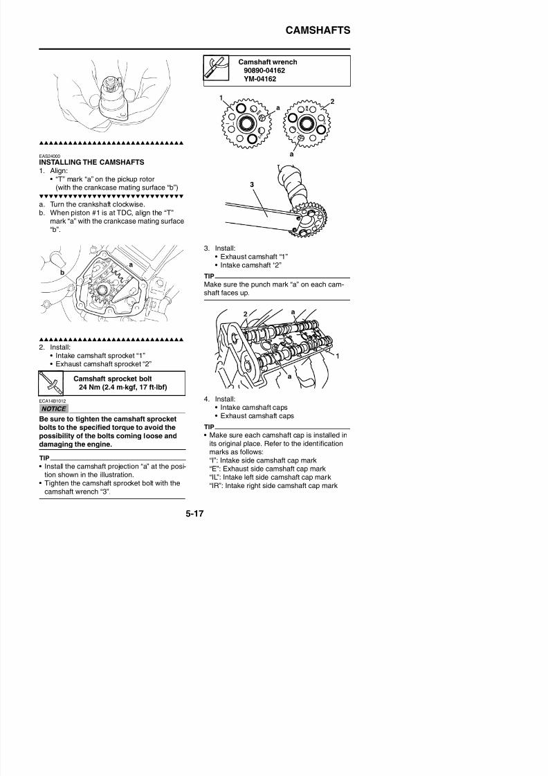
8/21/2019 Fz8 - Service Manual
http://slidepdf.com/reader/full/fz8-service-manual 282/609
2. Install:• Intake camshaft sprocket “1”• Exhaust camshaft sprocket “2”
TIP
Make sure the punch mark “a” on each cam-shaft faces up.
Camshaft sprocket bolt
CAMSHAFTS
“EL”: Exhaust left side camshaft cap mark“ER”: Exhaust right side camshaft cap mark
• Make sure the arrow mark “a” on each cam-shaft points towards the right side of theengine.
5. Tighten:• Camshaft cap bolts
TIP
Tighten the camshaft cap bolts in stages andin a crisscross pattern, working from the innercaps out.
7. Install:
• Timing chain tensioner gasket
• Timing chain tensioner “1”• Timing chain tensioner bolts “2”
WARNING
EWA39P1502
Always use a new timing chain tensionergasket.
ECA5D01011
The arrow mark “a” on the timing chain ten-sioner should face up.
Camshaft cap bolt10 Nm (1.0 m·kgf, 7.2 ft·lbf)
Timing chain tensioner bolt10 Nm (1.0 m·kgf, 7.2 ft·lbf)
LOCTITE®
New
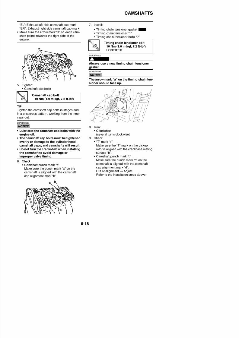
8/21/2019 Fz8 - Service Manual
http://slidepdf.com/reader/full/fz8-service-manual 283/609
ECA5D01009
• Lubricate the camshaft cap bolts with theengine oil.
• The camshaft cap bolts must be tightenedevenly or damage to the cylinder head,camshaft caps, and camshafts will result.
• Do not turn the crankshaft when installingthe camshaft to avoid damage orimproper valve timing.
6. Check:• Camshaft punch mark “a”
8. Turn:• Crankshaft
(several turns clockwise)
9. Check:• “T” mark “a”
Make sure the “T” mark on the pickuprotor is aligned with the crankcase matingsurface “b”.
• Camshaft punch mark “c”Make sure the punch mark “c” on thecamshaft is aligned with the camshaft
CAMSHAFTS
10. Measure:• Valve clearanceOut of specification → Adjust.Refer to “ADJUSTING THE VALVE
13. Install:• Spark plugs
I iti il “1”
Yamaha bond No.1215(Three bond No.1215®)90890-85505
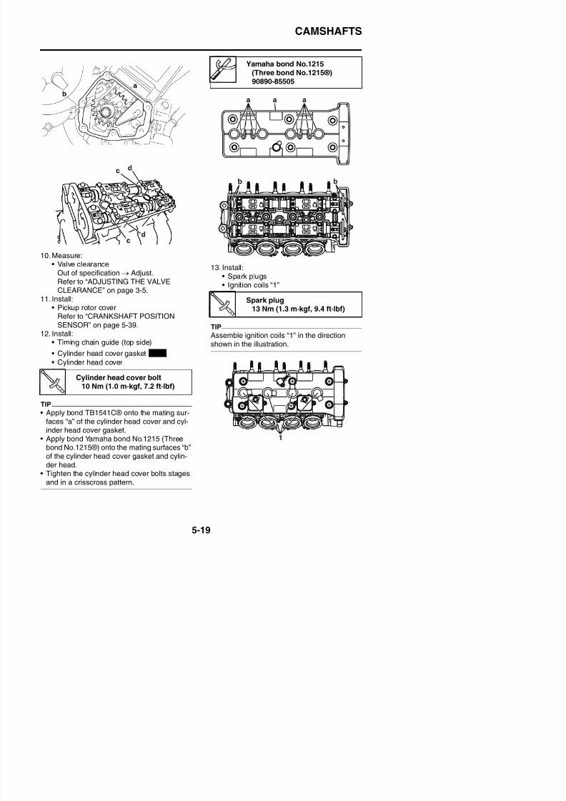
8/21/2019 Fz8 - Service Manual
http://slidepdf.com/reader/full/fz8-service-manual 284/609
Refer to ADJUSTING THE VALVECLEARANCE” on page 3-5.
11. Install:• Pickup rotor cover
Refer to “CRANKSHAFT POSITION
SENSOR” on page 5-39.12. Install:• Timing chain guide (top side)
• Cylinder head cover gasket
• Cylinder head cover
• Ignition coils “1”
TIPAssemble ignition coils “1” in the directionshown in the illustration.
Cylinder head cover bolt10 Nm (1.0 m·kgf, 7.2 ft·lbf)
New
Spark plug13 Nm (1.3 m·kgf, 9.4 ft·lbf)
CYLINDER HEAD
EAS24100
CYLINDER HEAD
Removing the cylinder head
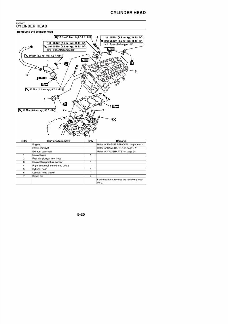
8/21/2019 Fz8 - Service Manual
http://slidepdf.com/reader/full/fz8-service-manual 285/609
Order Job/Parts to remove Q’ty Remarks
Engine Refer to “ENGINE REMOVAL” on page 5-3.
Intake camshaft Refer to “CAMSHAFTS” on page 5-11.
Exhaust camshaft Refer to “CAMSHAFTS” on page 5-11.
1 Coolant pipe 1
2 Fast idle plunger inlet hose 1
CYLINDER HEAD
EAS24120
REMOVING THE CYLINDER HEAD1. Remove:
• Intake camshaft• Exhaust camshaft
Refer to “REMOVING THE CAM-SHAFTS” on page 5-13.
2. Remove:• Cylinder head nuts• Cylinder head bolts
TIP
• Loosen the nuts in the proper sequence asshown.
• Loosen each nut 1/2 of a turn at a time. Afterall of the nuts are fully loosened, remove
them.
a. Place a straightedge “1” and a thicknessgauge “2” across the cylinder head.
Thickness gauge90890-03180Feeler gauge set
YU-26900-9
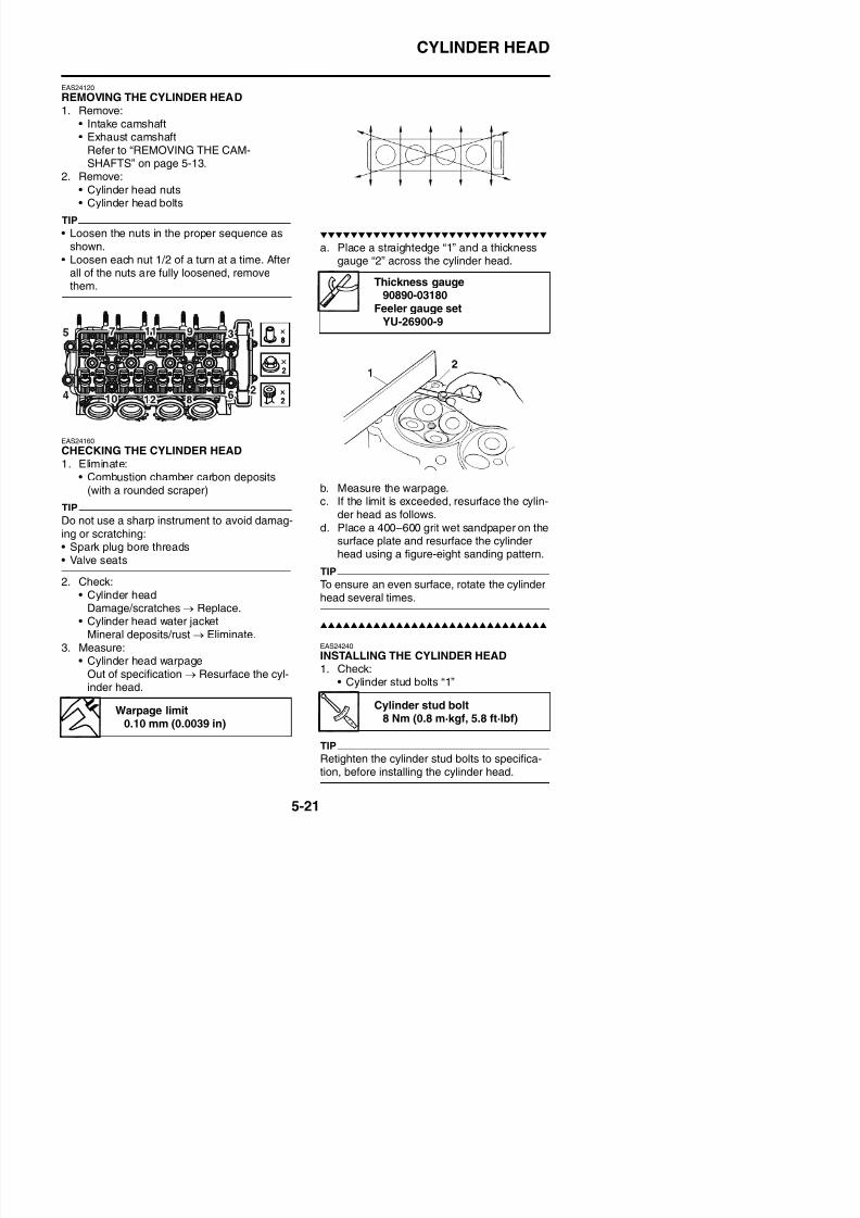
8/21/2019 Fz8 - Service Manual
http://slidepdf.com/reader/full/fz8-service-manual 286/609
EAS24160
CHECKING THE CYLINDER HEAD1. Eliminate:
• Combustion chamber carbon deposits(with a rounded scraper)
TIP
Do not use a sharp instrument to avoid damag-ing or scratching:• Spark plug bore threads• Valve seats
2. Check:• Cylinder head
b. Measure the warpage.
c. If the limit is exceeded, resurface the cylin-der head as follows.
d. Place a 400–600 grit wet sandpaper on thesurface plate and resurface the cylinderhead using a figure-eight sanding pattern.
TIP
To ensure an even surface, rotate the cylinderhead several times.
CYLINDER HEAD
2. Install:
• Cylinder head gasket “1”
• Dowel pins
3. Install:• Cylinder head
5. Install:• Exhaust camshaft• Intake camshaft
Refer to “INSTALLING THE CAM-
SHAFTS” on page 5-17.
New
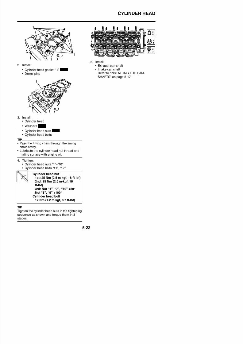
8/21/2019 Fz8 - Service Manual
http://slidepdf.com/reader/full/fz8-service-manual 287/609
• Washers
• Cylinder head nuts
• Cylinder head bolts
TIP
• Pass the timing chain through the timingchain cavity.
• Lubricate the cylinder head nut thread andmating surface with engine oil.
4. Tighten:• Cylinder head nuts “1”–“10”• Cylinder head bolts “11”, “12”
New
New
VALVES AND VALVE SPRINGS
EAS24270
VALVES AND VALVE SPRINGS
Removing the valves and valve springs
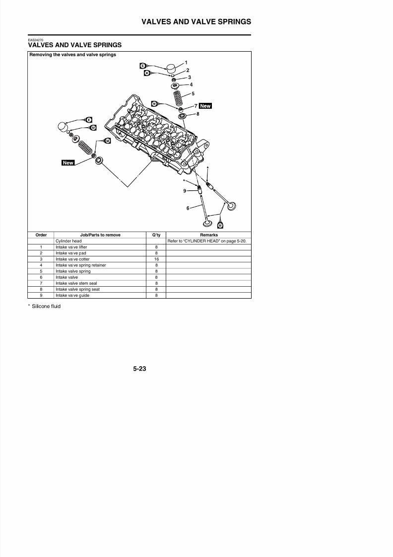
8/21/2019 Fz8 - Service Manual
http://slidepdf.com/reader/full/fz8-service-manual 288/609
Order Job/Parts to remove Q’ty Remarks
Cylinder head Refer to “CYLINDER HEAD” on page 5-20.
1 Intake valve lifter 8
2 Intake valve pad 8
3 Intake valve cotter 16
4 Intake valve spring retainer 8
5 Intake valve spring 8
VALVES AND VALVE SPRINGS
Removing the valves and valve springs
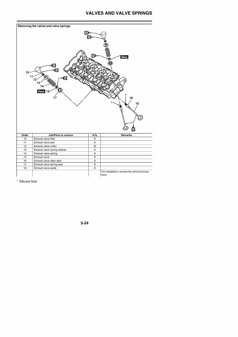
8/21/2019 Fz8 - Service Manual
http://slidepdf.com/reader/full/fz8-service-manual 289/609
Order Job/Parts to remove Q’ty Remarks
10 Exhaust valve lifter 811 Exhaust valve pad 8
12 Exhaust valve cotter 16
13 Exhaust valve spring retainer 8
14 Exhaust valve spring 8
15 Exhaust valve 8
16 Exhaust valve stem seal 8
17 Exhaust valve spring seat 8
VALVES AND VALVE SPRINGS
EAS24280
REMOVING THE VALVESThe following procedure applies to all of thevalves and related components.
TIP
Before removing the internal parts of the cylin-der head (e.g., valves, valve springs, valve
seats), make sure the valves properly seal.
1. Remove:• Valve lifter “1”• Valve pad “2”
TIP
Make a note of the position of each valve lifter
and valve pad so that they can be reinstalled in
their original place.
3. Remove:• Valve cotters
TIP
Remove the valve cotters by compressing thevalve spring with the valve spring compressor“1” and the valve spring compressor attach-ment “2”.
Valve spring compressor90890-04019YM-04019
Valve spring compressorattachment
90890-04108Valve spring compressor
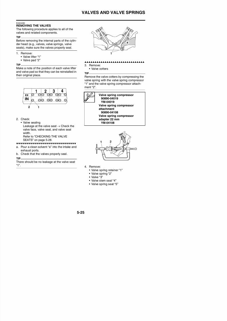
8/21/2019 Fz8 - Service Manual
http://slidepdf.com/reader/full/fz8-service-manual 290/609
2. Check:• Valve sealing
Leakage at the valve seat → Check thevalve face, valve seat, and valve seat
width.Refer to “CHECKING THE VALVESEATS” on page 5-28.
a. Pour a clean solvent “a” into the intake andexhaust ports.
b. Check that the valves properly seal.
TIP
Valve spring compressoradapter 22 mm
YM-04108
VALVES AND VALVE SPRINGS
TIP
Identify the position of each part very carefullyso that it can be reinstalled in its original place.
EAS24290
CHECKING THE VALVES AND VALVEGUIDESThe following procedure applies to all of thevalves and valve guides.1. Measure:
• Valve-stem-to-valve-guide clearanceOut of specification → Replace the valve
guide.
2. Replace:
• Valve guide
TIP
To ease valve guide removal and installation,and to maintain the correct fit, heat the cylinderhead to 100 °C (212 °F) in an oven.
• Valve-stem-to-valve-guide clearance =Valve guide inside diameter “a” -Valve stem diameter “b”
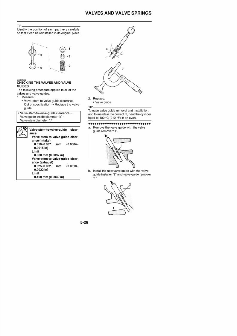
8/21/2019 Fz8 - Service Manual
http://slidepdf.com/reader/full/fz8-service-manual 291/609
a. Remove the valve guide with the valveguide remover “1”.Valve-stem-to-valve-guide clear-
ance
Valve-stem-to-valve-guide clear-ance (intake)0.010–0.037 mm (0.0004–0.0015 in)
Limit0.080 mm (0.0032 in)
Valve-stem-to-valve-guide clear-ance (exhaust)
VALVES AND VALVE SPRINGS
c. After installing the valve guide, bore thevalve guide with the valve guide reamer “3”to obtain the proper valve-stem-to-valve-guide clearance.
TIP
After replacing the valve guide, reface thevalve seat.
6. Measure:• Valve stem runout
Out of specification → Replace the valve.
TIP
• When installing a new valve, always replacethe valve guide.
• If the valve is removed or replaced, alwaysreplace the valve stem seal.
Valve guide remover (ø4)90890-04111
Valve guide remover (4.0 mm)YM-04111
Valve guide installer (ø4)
90890-04112Valve guide installer (4.0 mm)
YM-04112Valve guide reamer (ø4)
Valve margin thicknessValve margin thickness (intake)
0.50–0.90 mm (0.0197–0.0354in)
Valve margin thickness(exhaust)
0.50–0.90 mm (0.0197–0.0354
in)
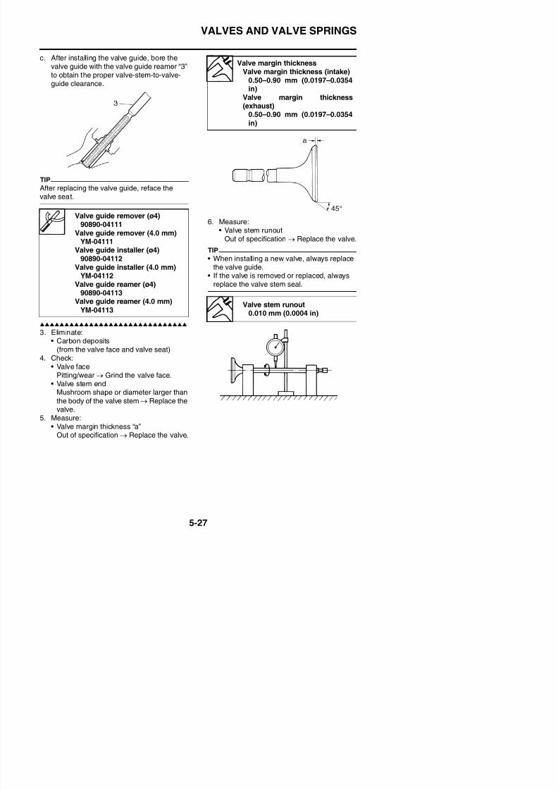
8/21/2019 Fz8 - Service Manual
http://slidepdf.com/reader/full/fz8-service-manual 292/609
3. Eliminate:• Carbon deposits
(from the valve face and valve seat)4. Check:
• Valve facePitting/wear → Grind the valve face.
• Valve stem end
pg ( )90890-04113
Valve guide reamer (4.0 mm)
YM-04113Valve stem runout
0.010 mm (0.0004 in)
VALVES AND VALVE SPRINGS
EAS24300
CHECKING THE VALVE SEATSThe following procedure applies to all of thevalves and valve seats.1. Eliminate:
• Carbon deposits(from the valve face and valve seat)
2. Check:
• Valve seatPitting/wear → Replace the cylinderhead.
3. Measure:• Valve seat width “a”
Out of specification → Replace the cylin-der head.
c. Press the valve through the valve guideand onto the valve seat to make a clearimpression.
d. Measure the valve seat width.
TIP
Where the valve seat and valve face contactedone another, the blueing will have been
removed.
4. Lap:• Valve face• Valve seat
TIP
After replacing the cylinder head or replacingthe valve and valve guide, the valve seat andvalve face should be lapped.
a. Apply a coarse lapping compound “a” tothe valve face.
ECA13790
Do not let the lapping compound enter thegap between the valve stem and the valve
guide.
Valve seat widthValve seat width (intake)
0.90–1.10 mm (0.0354–0.0433
in)Limit
1.60 mm (0.06 in)Valve seat width (exhaust)
0.90–1.10 mm (0.0354–0.0433
in)Limit
1.60 mm (0.06 in)
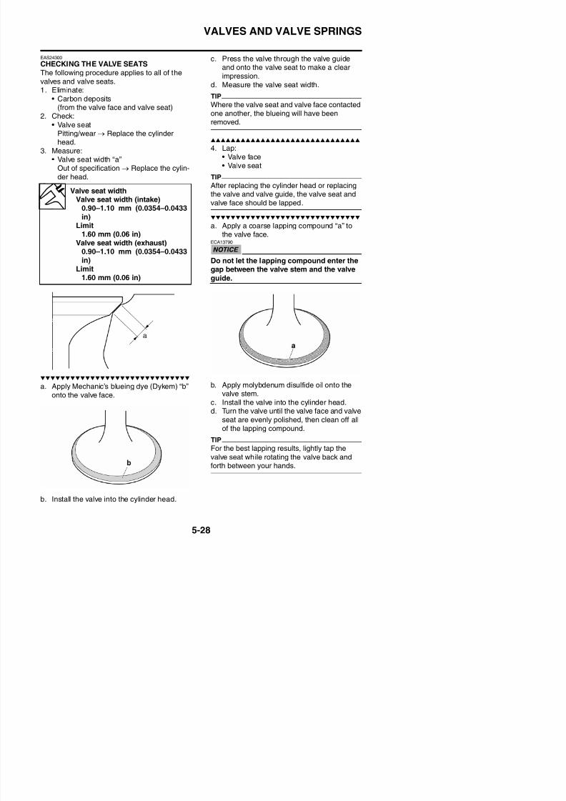
8/21/2019 Fz8 - Service Manual
http://slidepdf.com/reader/full/fz8-service-manual 293/609
a. Apply Mechanic’s blueing dye (Dykem) “b”onto the valve face.
b. Apply molybdenum disulfide oil onto thevalve stem.
VALVES AND VALVE SPRINGS
e. Apply a fine lapping compound to the valveface and repeat the above steps.
f. After every lapping procedure, be sure toclean off all of the lapping compound fromthe valve face and valve seat.
g. Apply Mechanic’s blueing dye (Dykem) “b”onto the valve face.
EAS24310
CHECKING THE VALVE SPRINGSThe following procedure applies to all of thevalve springs.1. Measure:
• Valve spring free length “a”Out of specification→ Replace the valvespring.
Valve spring free lengthFree length (intake)
38.62 mm (1.52 in)Limit
36.69 mm (1.44 in)Free length (exhaust)
38.62 mm (1.52 in)
Limit36.69 mm (1.44 in)
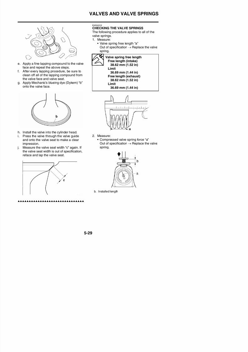
8/21/2019 Fz8 - Service Manual
http://slidepdf.com/reader/full/fz8-service-manual 294/609
h. Install the valve into the cylinder head.i. Press the valve through the valve guide
and onto the valve seat to make a clear
impression. j. Measure the valve seat width “c” again. Ifthe valve seat width is out of specification,reface and lap the valve seat.
2. Measure:• Compressed valve spring force “a”
Out of specification→
Replace the valvespring.
VALVES AND VALVE SPRINGS
3. Measure:• Valve spring tilt “a”
Out of specification → Replace the valvespring.
EAS24340
INSTALLING THE VALVESThe following procedure applies to all of thevalves and related components.1. Deburr:
• Valve stem end(with an oil stone)
2. Lubricate:• Valve stem “1”• Valve stem seal “2”
(with the recommended lubricant)
Installed compression springforce (intake)
130.60–150.20 N (13.32–15.32kgf, 29.36–33.76 lbf)
Installed compression springforce (exhaust)
130.60–150.20 N (13.32–15.32
kgf, 29.36–33.76 lbf)Installed length (intake)
33.00 mm (1.30 in)Installed length (exhaust)
33.00 mm (1.30 in)
Spring tilt limitSpring tilt (intake)
2.5° /1.7 mm (0.067 in)Spring tilt (exhaust)
2.5° /1.7 mm (0.067 in)Recommended lubricant
Molybdenum disulfide oil
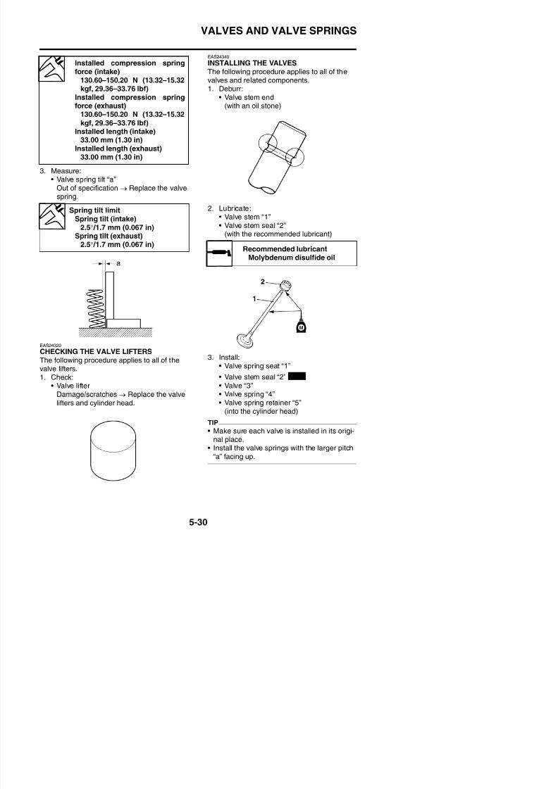
8/21/2019 Fz8 - Service Manual
http://slidepdf.com/reader/full/fz8-service-manual 295/609
EAS24320
CHECKING THE VALVE LIFTERSThe following procedure applies to all of thevalve lifters.1. Check:
• Valve lifter
3. Install:• Valve spring seat “1”
• Valve stem seal “2”
• Valve “3”
New
VALVES AND VALVE SPRINGS
4. Install:• Valve cotters “1”
TIP
Install the valve cotters by compressing thevalve spring with the valve spring compressor
5. To secure the valve cotters onto the valvestem, lightly tap the valve tip with a soft-face hammer.
ECA13800
Hitting the valve tip with excessive forcecould damage the valve.
6. Lubricate:• Valve pad
(with the recommended lubricant)
• Valve lifter
(with the recommended lubricant)
b. Smaller pitch
Recommended lubricant
Molybdenum disulfide oil
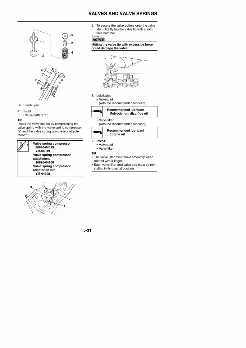
8/21/2019 Fz8 - Service Manual
http://slidepdf.com/reader/full/fz8-service-manual 296/609
valve spring with the valve spring compressor“2” and the valve spring compressor attach-
ment “3”.
7. Install:
• Valve pad• Valve lifter
TIP
• The valve lifter must move smoothly whenrotated with a finger.
• Each valve lifter and valve pad must be rein-stalled in its original position.
Valve spring compressor90890-04019YM-04019
Valve spring compressorattachment
90890-04108Valve spring compressoradapter 22 mm
Recommended lubricantEngine oil
GENERATOR
EAS24480
GENERATOR
Removing the generator
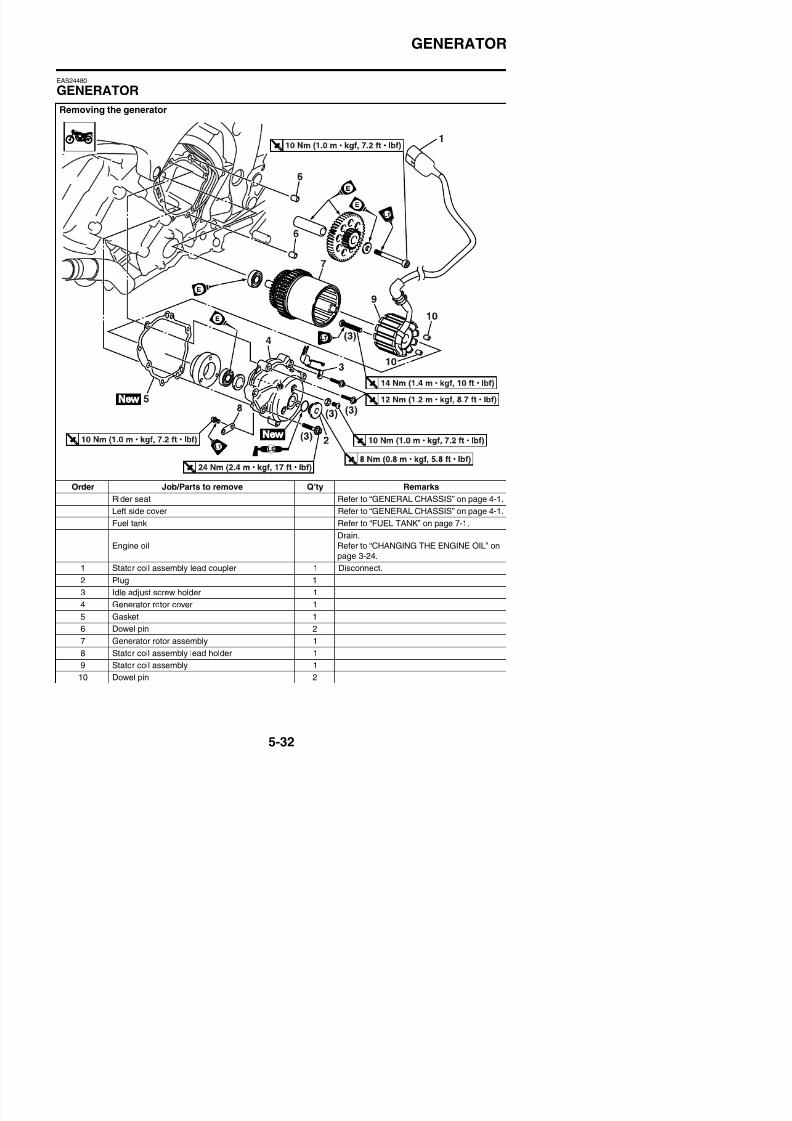
8/21/2019 Fz8 - Service Manual
http://slidepdf.com/reader/full/fz8-service-manual 297/609
Order Job/Parts to remove Q’ty Remarks
Rider seat Refer to “GENERAL CHASSIS” on page 4-1.
Left side cover Refer to “GENERAL CHASSIS” on page 4-1.
Fuel tank Refer to “FUEL TANK” on page 7-1.
Engine oil
Drain.
Refer to “CHANGING THE ENGINE OIL” on
GENERATOR
Removing the generator
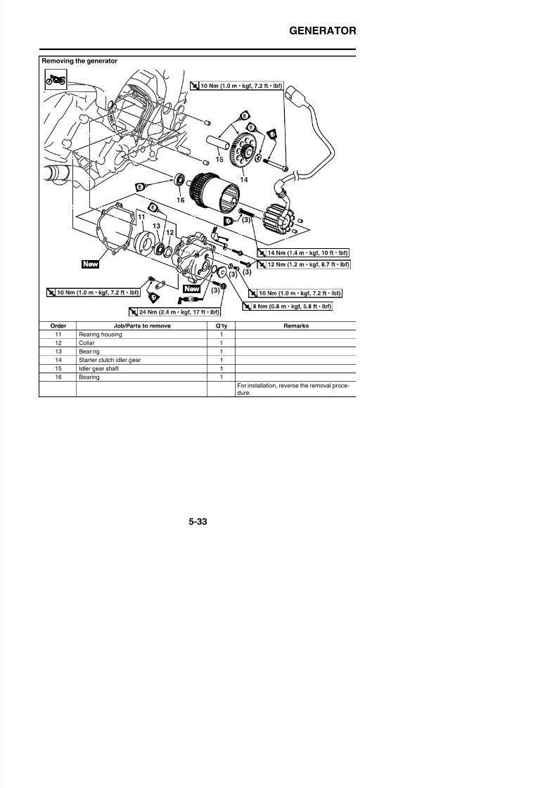
8/21/2019 Fz8 - Service Manual
http://slidepdf.com/reader/full/fz8-service-manual 298/609
Order Job/Parts to remove Q’ty Remarks11 Bearing housing 1
12 Collar 1
13 Bearing 1
14 Starter clutch idler gear 1
15 Idler gear shaft 1
16 Bearing 1
For installation, reverse the removal proce-
GENERATOR
EAS24490
REMOVING THE GENERATOR1. Remove:
• Plug• Generator rotor cover “1”
TIP
• While pushing generator rotor, remove the
generator rotor cover.• Loosen each bolt 1/4 of a turn a time, instages and in a crisscross pattern.
• After all of the bolts are fully loosened,remove them.
2. Remove:• Generator rotor and starter clutch assem-
bly “1”
EAS24500
INSTALLING THE GENERATOR1. Install:
• Idle gear shaft• Idle gear “1”• Washer• Idle gear shaft bolt “2”
2. Install:• Generator rotor and starter clutch assem-
bly “1”
Idle gear shaft bolt10 Nm (1.0 m·kgf, 7.2 ft·lbf)LOCTITE®
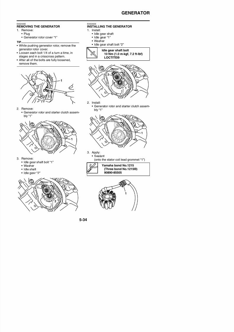
8/21/2019 Fz8 - Service Manual
http://slidepdf.com/reader/full/fz8-service-manual 299/609
3. Remove:• Idle gear shaft bolt “1”
3. Apply:• Sealant
(onto the stator coil lead grommet “1”)
GENERATOR
4. Install:
• Generator rotor cover gasket
• Generator rotor cover “1”
TIP
• First tighten the M8 bolts and then tighten theM6 bolts.
• Tighten the generator rotor cover bolts instages and in a crisscross pattern.
Generator rotor cover bolt (M8)22 Nm (2.2 m·kgf, 16 ft·lbf)
Generator rotor cover bolt (M6)
12 Nm (1.2 m·kgf, 8.7 ft·lbf)
New
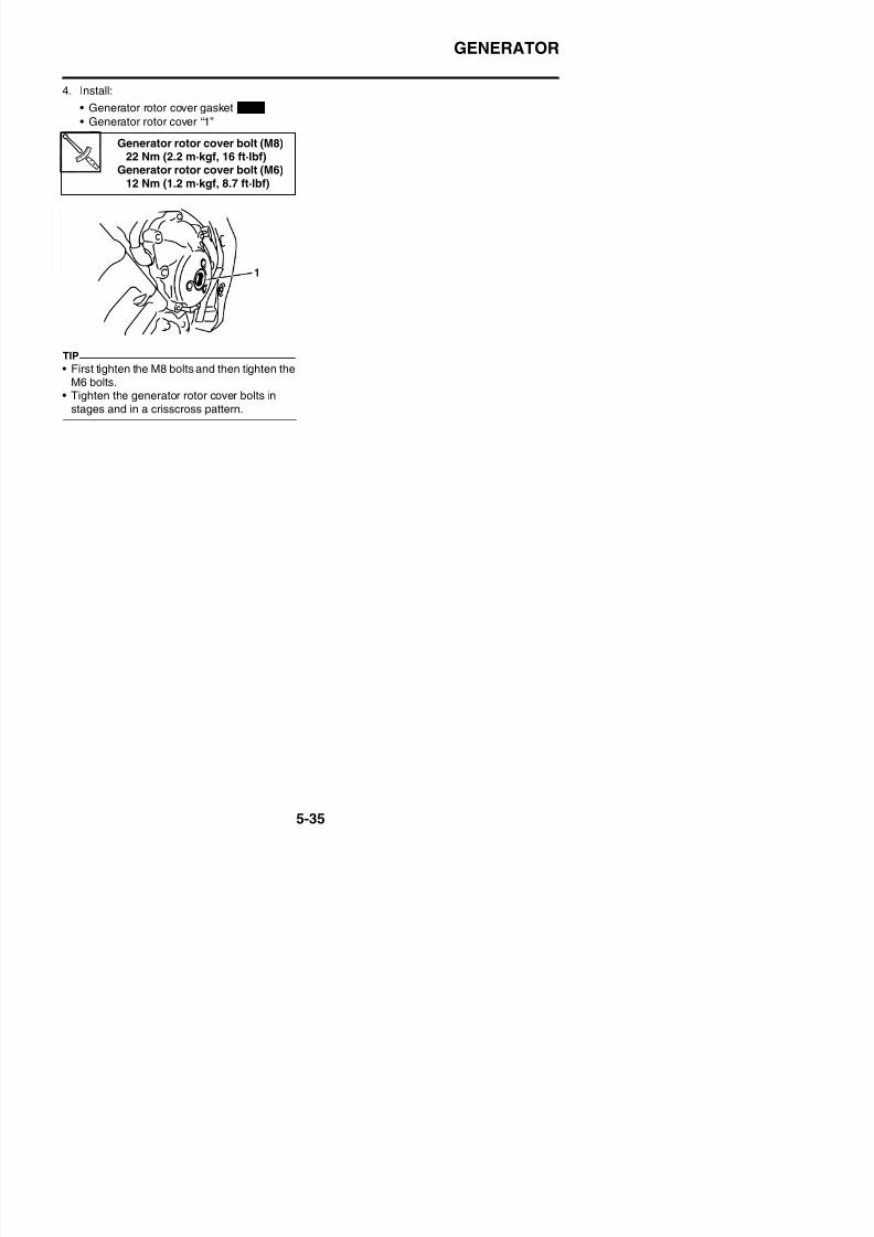
8/21/2019 Fz8 - Service Manual
http://slidepdf.com/reader/full/fz8-service-manual 300/609
STARTER CLUTCH
EAS24550
STARTER CLUTCH
Removing the starter clutch
Order Job/Parts to remove Q’ty Remarks
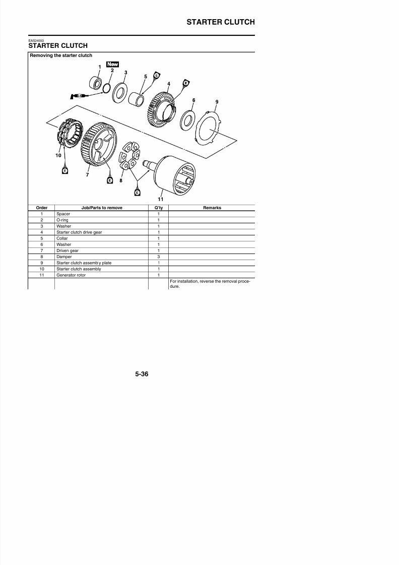
8/21/2019 Fz8 - Service Manual
http://slidepdf.com/reader/full/fz8-service-manual 301/609
1 Spacer 1
2 O-ring 1
3 Washer 1
4 Starter clutch drive gear 15 Collar 1
6 Washer 1
7 Driven gear 1
8 Damper 3
9 Starter clutch assembly plate 1
10 Starter clutch assembly 1
11 Generator rotor 1
STARTER CLUTCH
EAS24560
REMOVING THE STARTER CLUTCH1. Remove:
• Spacer “1”• O-ring “2”• Washer “3”
2. Remove:• Starter clutch drive gear “1”• Collar “2”• Washer “3”
EAS5D01018
CHECKING THE DAMPER1. Check:
• Dampers “1”
Damage/wear → Replace.
EAS24570
CHECKING THE STARTER CLUTCH
1. Check:• Starter clutch rollers “1”
Damage/wear → Replace.
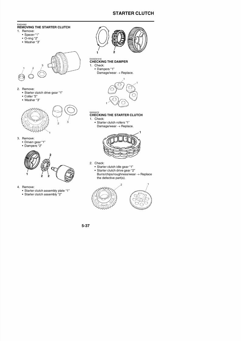
8/21/2019 Fz8 - Service Manual
http://slidepdf.com/reader/full/fz8-service-manual 302/609
3. Remove:
• Driven gear “1”• Dampers “2”
2. Check:• Starter clutch idle gear “1”
STARTER CLUTCH
3. Check:• Starter clutch gear’s contacting surfaces
Damage/pitting/wear → Replace thestarter clutch gear.
4. Check:• Starter clutch operation
a. Install the starter clutch drive gear “1” ontothe starter clutch and hold the driven gear.b. When turning the starter clutch drive gear
counterclockwise “A”, the driven gear andthe starter clutch drive gear should engage,otherwise the starter clutch is faulty andmust be replaced.
c. When turning the starter clutch drive gear
clockwise “B”, it should turn freely, other-wise the starter clutch is faulty and must bereplaced.
2. Install:• Generator rotor “1”• Dampers “2”• Driven gear “3”
TIP
• Be sure to install the damper to the drivengear so that the projections “a” is generator
side.• Lubricate the engine oil to damper.
3. Install:• Starter clutch drive gear “1”• Collar “2”
• Washer “3”
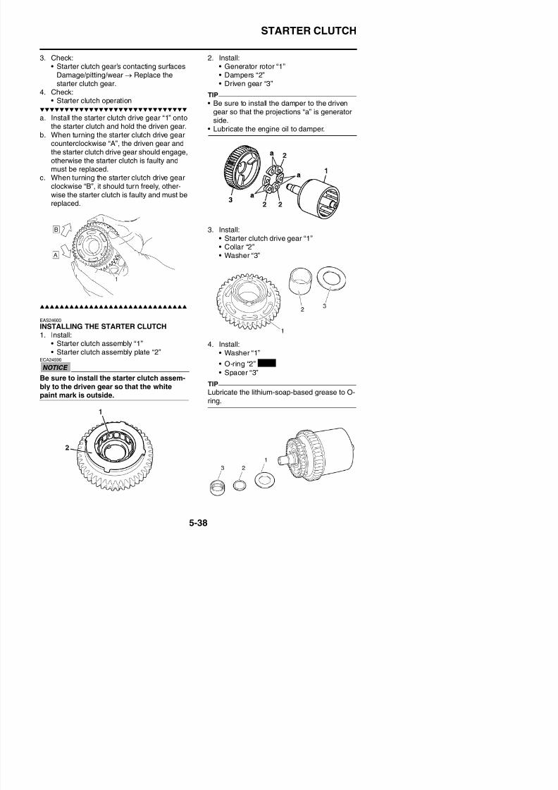
8/21/2019 Fz8 - Service Manual
http://slidepdf.com/reader/full/fz8-service-manual 303/609
EAS24600
INSTALLING THE STARTER CLUTCH1. Install:
• Starter clutch assembly “1”• Starter clutch assembly plate “2”
ECA24590
Be sure to install the starter clutch assem-bly to the driven gear so that the white
4. Install:• Washer “1”
• O-ring “2”
• Spacer “3”
TIP
New
CRANKSHAFT POSITION SENSOR
EAS24520
CRANKSHAFT POSITION SENSOR
Removing the crankshaft position sensor

8/21/2019 Fz8 - Service Manual
http://slidepdf.com/reader/full/fz8-service-manual 304/609
Order Job/Parts to remove Q’ty Remarks
Rider seat Refer to “GENERAL CHASSIS” on page 4-1.
Fuel tank Refer to “FUEL TANK” on page 7-1.
Engine oil
Drain.
Refer to “CHANGING THE ENGINE OIL” on
page 3-24.
1 Crankshaft position sensor lead coupler 1 Disconnect.
CRANKSHAFT POSITION SENSOR
EAS24530
REMOVING THE CRANKSHAFT POSITIONSENSOR1. Disconnect:
• Crankshaft position sensor lead coupler2. Remove:
• Crankshaft position sensor• O-rings
• Pickup rotor cover “1”
TIP
Loosen each bolt 1/4 of a turn at a time, instages and in a crisscross pattern.After all of the bolts are fully loosened, removethem.
EAS24540
INSTALLING THE CRANKSHAFT POSITION
2. Connect:• Crankshaft position sensor lead coupler
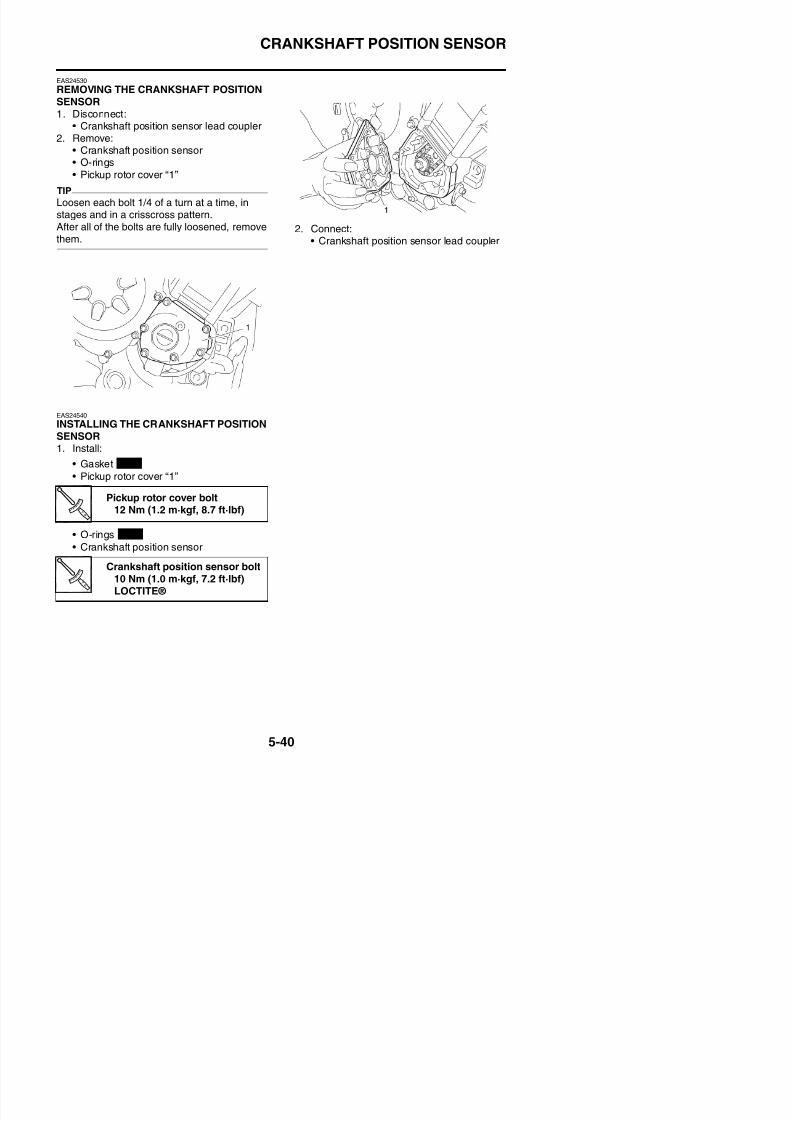
8/21/2019 Fz8 - Service Manual
http://slidepdf.com/reader/full/fz8-service-manual 305/609
INSTALLING THE CRANKSHAFT POSITIONSENSOR1. Install:
• Gasket• Pickup rotor cover “1”
• O-rings
• Crankshaft position sensor
Pickup rotor cover bolt12 Nm (1.2 m·kgf, 8.7 ft·lbf)
New
New
ELECTRIC STARTER
EAS24780
ELECTRIC STARTER
Removing the starter motor
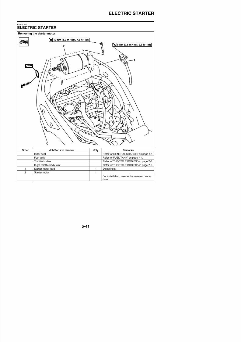
8/21/2019 Fz8 - Service Manual
http://slidepdf.com/reader/full/fz8-service-manual 306/609
Order Job/Parts to remove Q’ty Remarks
Rider seat Refer to “GENERAL CHASSIS” on page 4-1.
Fuel tank Refer to “FUEL TANK” on page 7-1.
Throttle bodies Refer to “THROTTLE BODIES” on page 7-5.
Right throttle body joint Refer to “THROTTLE BODIES” on page 7-5.
1 Starter motor lead 1 Disconnect.
ELECTRIC STARTER
Disassembling the starter motor
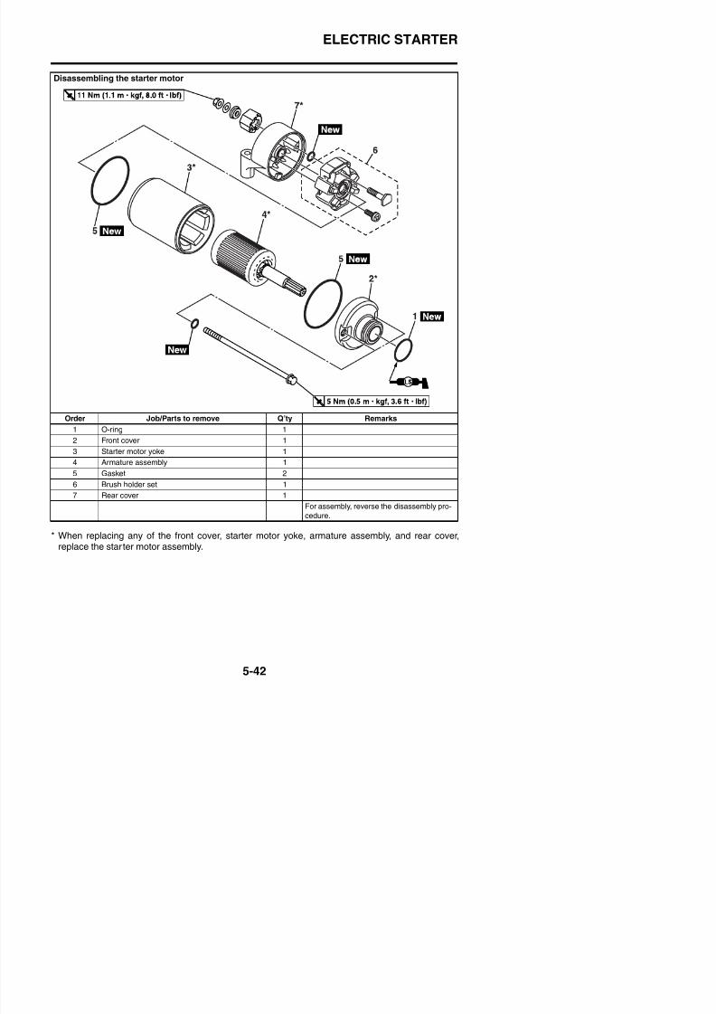
8/21/2019 Fz8 - Service Manual
http://slidepdf.com/reader/full/fz8-service-manual 307/609
Order Job/Parts to remove Q’ty Remarks1 O-ring 1
2 Front cover 1
3 Starter motor yoke 1
4 Armature assembly 1
5 Gasket 2
6 Brush holder set 1
7 Rear cover 1
ELECTRIC STARTER
EAS24791
CHECKING THE STARTER MOTOR1. Check:
• CommutatorDirt → Clean with 600 grit sandpaper.
2. Measure:• Mica undercut “a”
Out of specification → Scrape the mica to
the proper measurement with a hacksawblade that has been grounded to fit thecommutator.
TIP
The mica of the commutator must be undercutto ensure proper operation of the commutator.
3 Meas re
4. Measure:• Brush length “a”
Out of specification → Replace the brushholder set.
Mica undercut (depth)0.70 mm (0.03 in)
1. Commutator resistance
2. Insulation resistance
Brush overall length12.0 mm (0.47 in)
Limit6.50 mm (0.26 in)
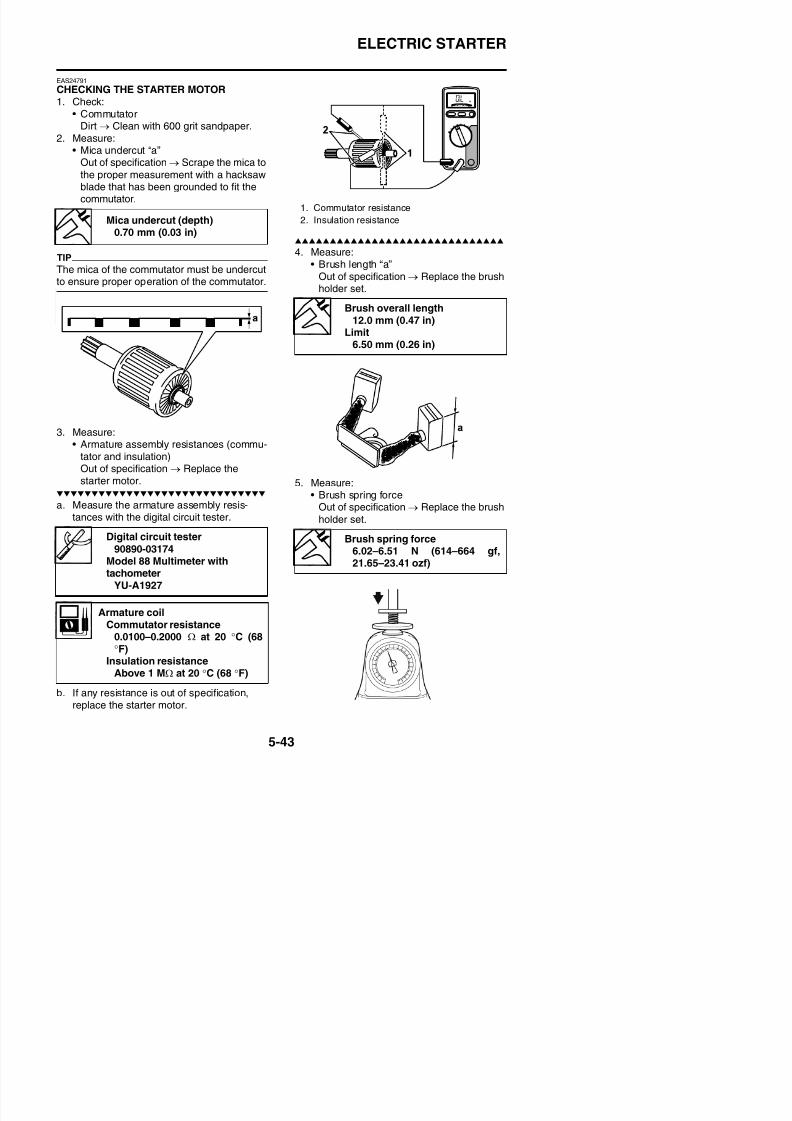
8/21/2019 Fz8 - Service Manual
http://slidepdf.com/reader/full/fz8-service-manual 308/609
3. Measure:• Armature assembly resistances (commu-
tator and insulation)
Out of specification → Replace thestarter motor.
a. Measure the armature assembly resis-tances with the digital circuit tester.
5. Measure:• Brush spring force
Out of specification → Replace the brush
holder set.
Digital circuit tester
90890-03174Brush spring force
6.02–6.51 N (614–664 gf,
ELECTRIC STARTER
6. Check:• Gear teeth
Damage/wear → Replace the startermotor.
7. Check:• Bearing• Oil seal
Damage/wear → Replace the startermotor.
EAS24800
ASSEMBLING THE STARTER MOTOR1. Install:
• Brush holder set2. Install:
• Rear cover “1”
• Starter motor yoke “2”• Front cover “3”
TIP
Align the match marks “a” on the starter motoryoke with the match marks “b” on the front andrear cover.
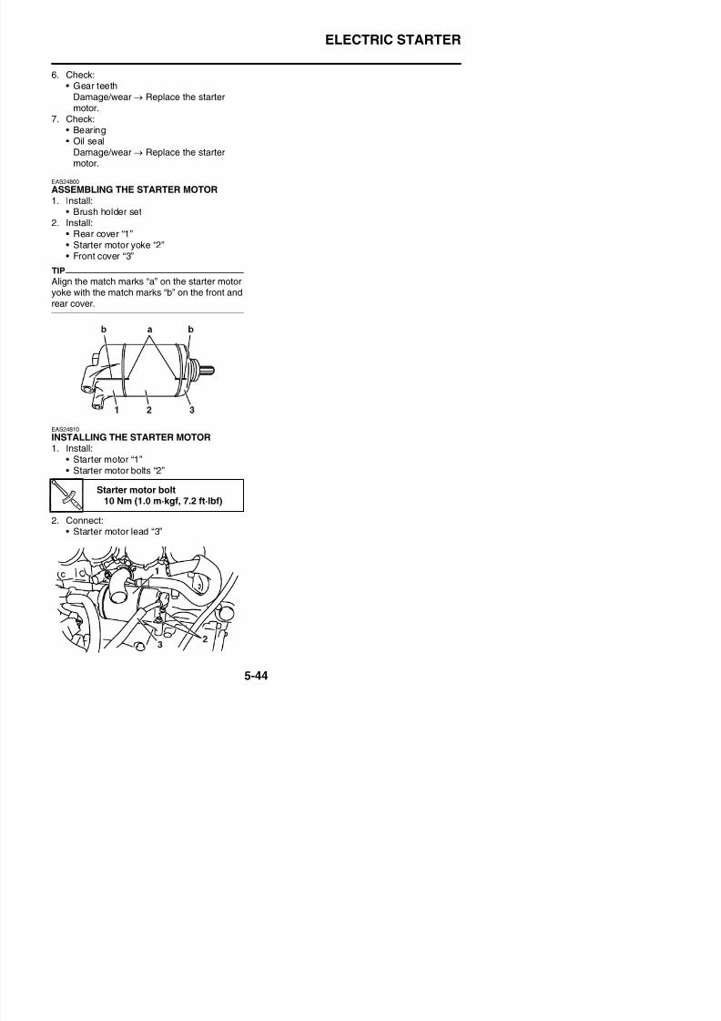
8/21/2019 Fz8 - Service Manual
http://slidepdf.com/reader/full/fz8-service-manual 309/609
EAS24810
INSTALLING THE STARTER MOTOR1. Install:
• Starter motor “1”• Starter motor bolts “2”
Starter motor bolt10 Nm (1.0 m·kgf, 7.2 ft·lbf)
CLUTCH
EAS25061
CLUTCH
Removing the clutch cover
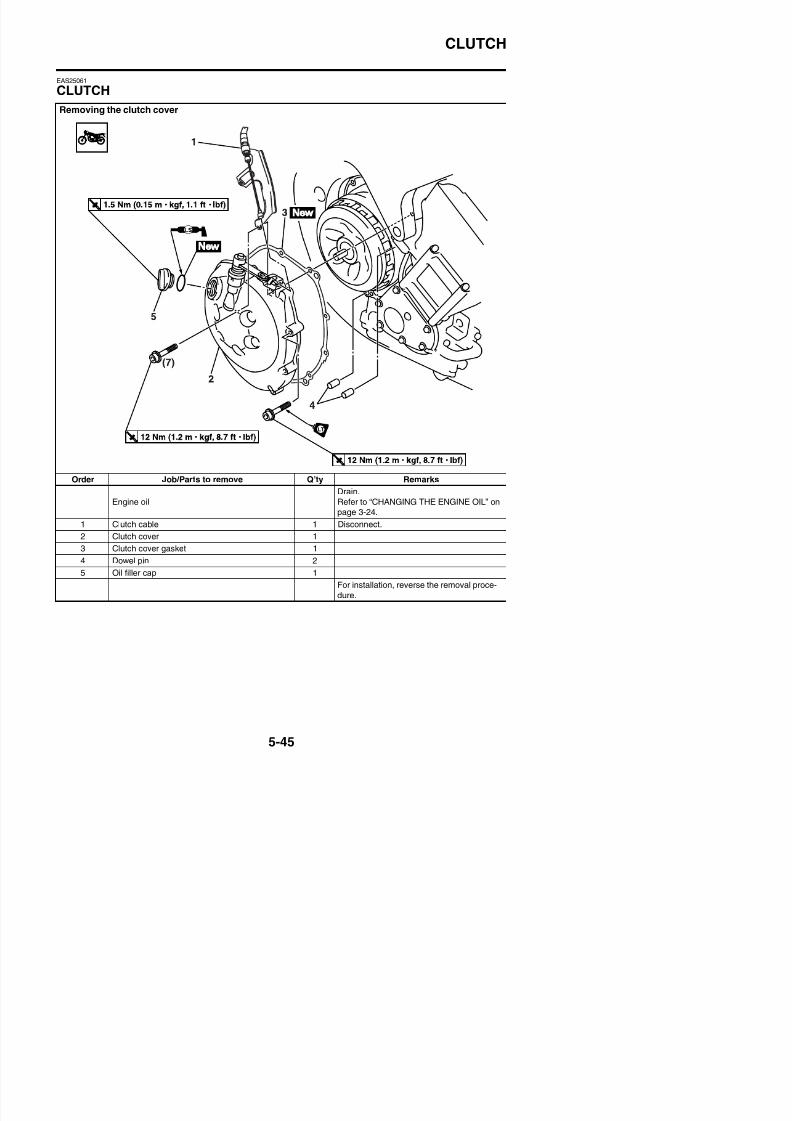
8/21/2019 Fz8 - Service Manual
http://slidepdf.com/reader/full/fz8-service-manual 310/609
Order Job/Parts to remove Q’ty Remarks
Engine oil
Drain.
Refer to “CHANGING THE ENGINE OIL” on
page 3-24.
1 Clutch cable 1 Disconnect.
2 Clutch cover 1
3 Clutch cover gasket 1
CLUTCH
Removing the pull lever shaft
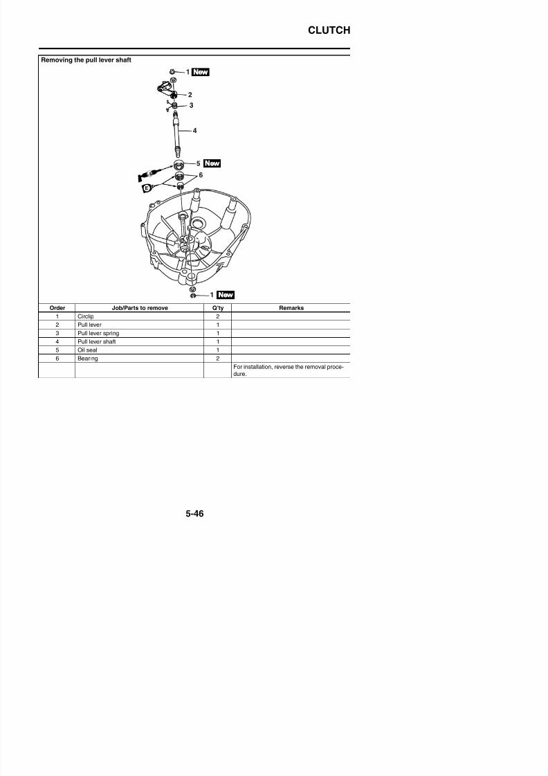
8/21/2019 Fz8 - Service Manual
http://slidepdf.com/reader/full/fz8-service-manual 311/609
Order Job/Parts to remove Q’ty Remarks
1 Circlip 2
2 Pull lever 1
3 Pull lever spring 1
4 Pull lever shaft 1
5 Oil seal 1
6 Bearing 2
For installation, reverse the removal proce-
dure.
CLUTCH
Removing the clutch
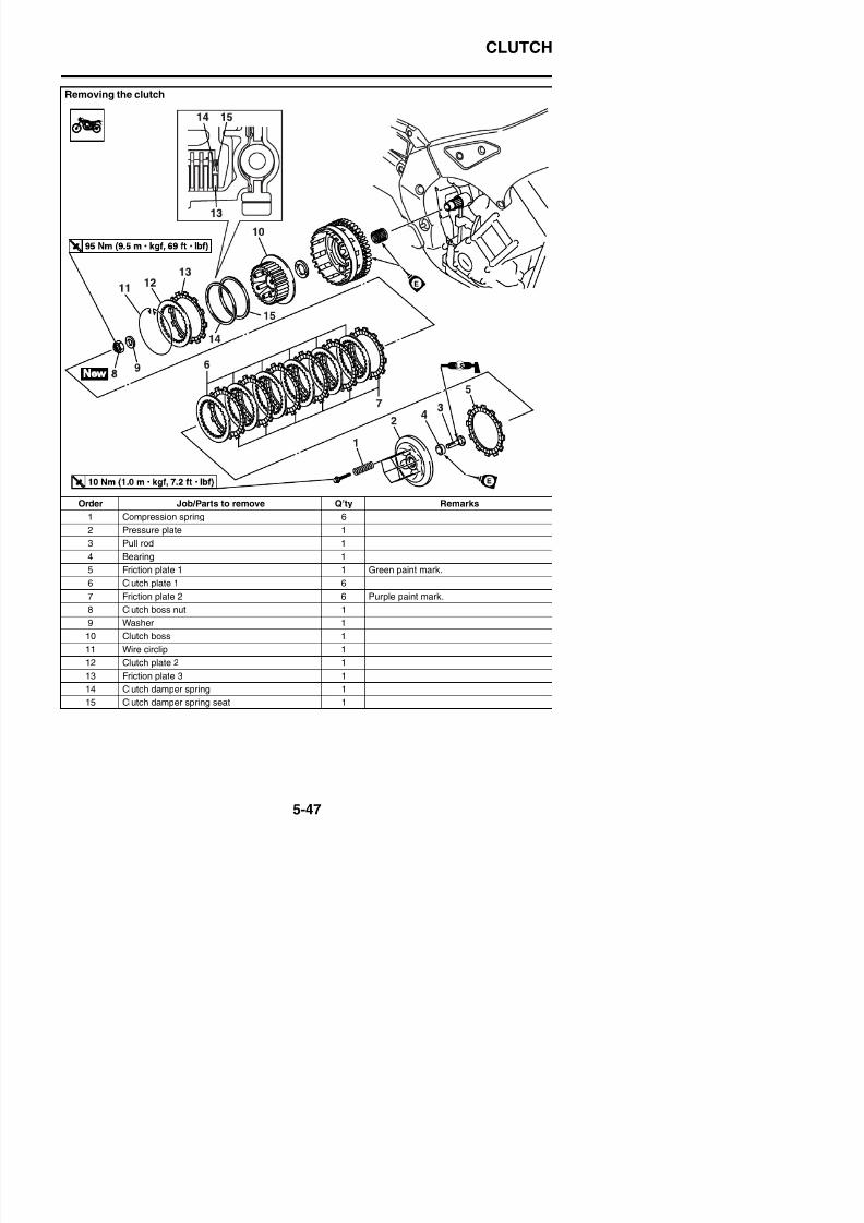
8/21/2019 Fz8 - Service Manual
http://slidepdf.com/reader/full/fz8-service-manual 312/609
Order Job/Parts to remove Q’ty Remarks
1 Compression spring 6
2 Pressure plate 1
3 Pull rod 1
4 Bearing 1
5 Friction plate 1 1 Green paint mark.
6 Clutch plate 1 6
7 Friction plate 2 6 Purple paint mark.
C
CLUTCH
Removing the clutch
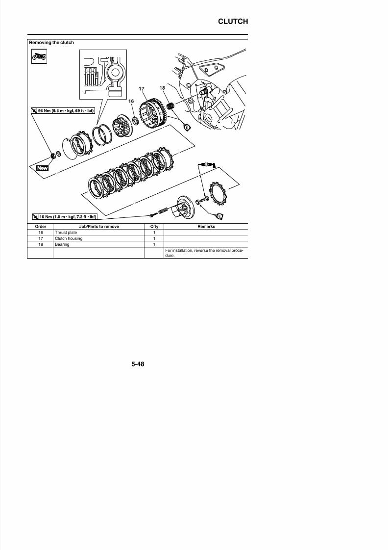
8/21/2019 Fz8 - Service Manual
http://slidepdf.com/reader/full/fz8-service-manual 313/609
Order Job/Parts to remove Q’ty Remarks
16 Thrust plate 1
17 Clutch housing 1
18 Bearing 1
For installation, reverse the removal proce-
dure.
CLUTCH
EAS30712
REMOVING THE CLUTCH1. Remove:
• Clutch cover “1”• Gasket
TIP
Loosen each bolt 1/4 of a turn at a time, in
stages and in a crisscross pattern.After all of the bolts are fully loosened, removethem.
2. Remove:• Compression spring bolts “1”
• Compression springs• Pressure plate “2”• Pull rod “3”
4. Remove:• Clutch plate 1 “1”• Friction plate 2
5. Straighten the clutch boss nut rib “a”.
6. Loosen:• Clutch boss nut “1”
TIP
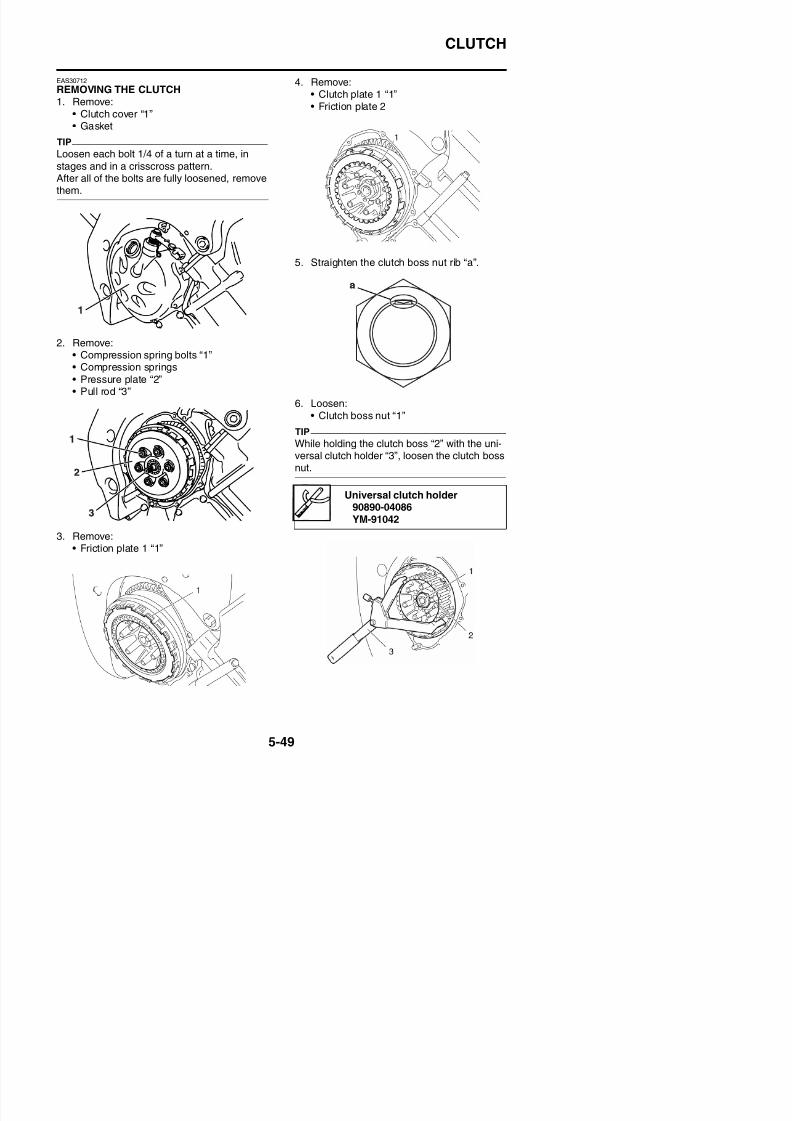
8/21/2019 Fz8 - Service Manual
http://slidepdf.com/reader/full/fz8-service-manual 314/609
3. Remove:• Friction plate 1 “1”
While holding the clutch boss “2” with the uni-versal clutch holder “3”, loosen the clutch boss
nut.
Universal clutch holder90890-04086YM-91042
CLUTCH
7. Remove:• Clutch boss nut• Washer• Clutch boss assembly• Thrust plate
8. Remove:• Wire circlip “1”
TIPThere is a built-in damper between the clutchboss and the clutch plate. It is not necessary toremove the wire circlip “1” and disassemble the
built-in damper unless there is serious clutchchattering.
9. Remove:• Clutch plate 2 “1”• Friction plate 3 “2”
EAS25100
CHECKING THE FRICTION PLATESThe following procedure applies to all of thefriction plates.1. Check:
• Friction plateDamage/wear → Replace the frictionplates as a set.
2. Measure:• Friction plate thickness
Out of specification → Replace the fric-tion plates as a set.
TIP
Measure the friction plate at four places.
Friction plate thickness2.92–3.08 mm (0.115–0.121 in)
Wear limit2.82 mm (0.1110 in)
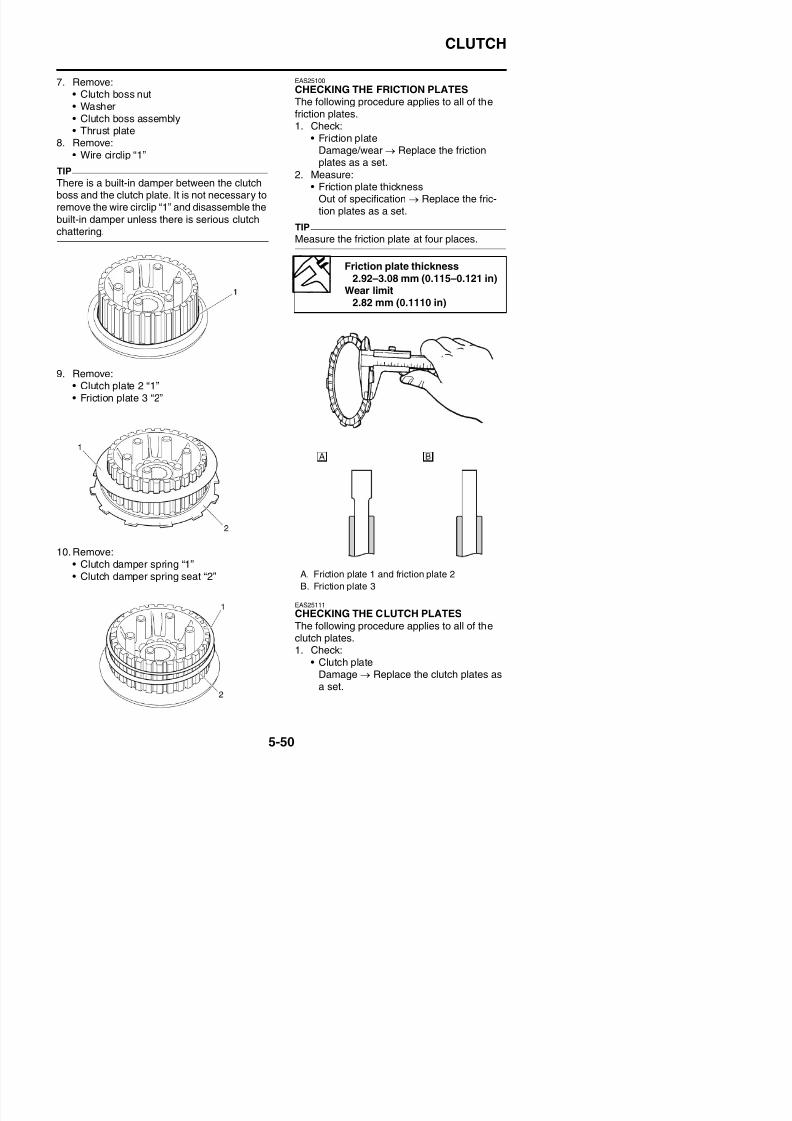
8/21/2019 Fz8 - Service Manual
http://slidepdf.com/reader/full/fz8-service-manual 315/609
10. Remove:
CLUTCH
2. Measure:• Clutch plate warpage
(with a surface plate and thickness gauge“1”)Out of specification → Replace the clutchplates as a set.
EAS25140
CHECKING THE CLUTCH SPRINGSThe following procedure applies to all of theclutch springs.1. Check:
• Clutch spring
EAS25150
CHECKING THE CLUTCH HOUSING1. Check:
• Clutch housing dogsDamage/pitting/wear → Deburr the clutchhousing dogs or replace the clutch hous-ing.
TIP
Pitting on the clutch housing dogs will causeerratic clutch operation.
2. Check:• Bearing
Damage/wear → Replace the bearingand clutch housing.
EAS25160
CHECKING THE CLUTCH BOSS
1. Check:• Clutch boss splines
/ /
Thickness gauge
90890-03180Feeler gauge set
YU-26900-9
Warpage limit0.10 mm (0.0039 in)
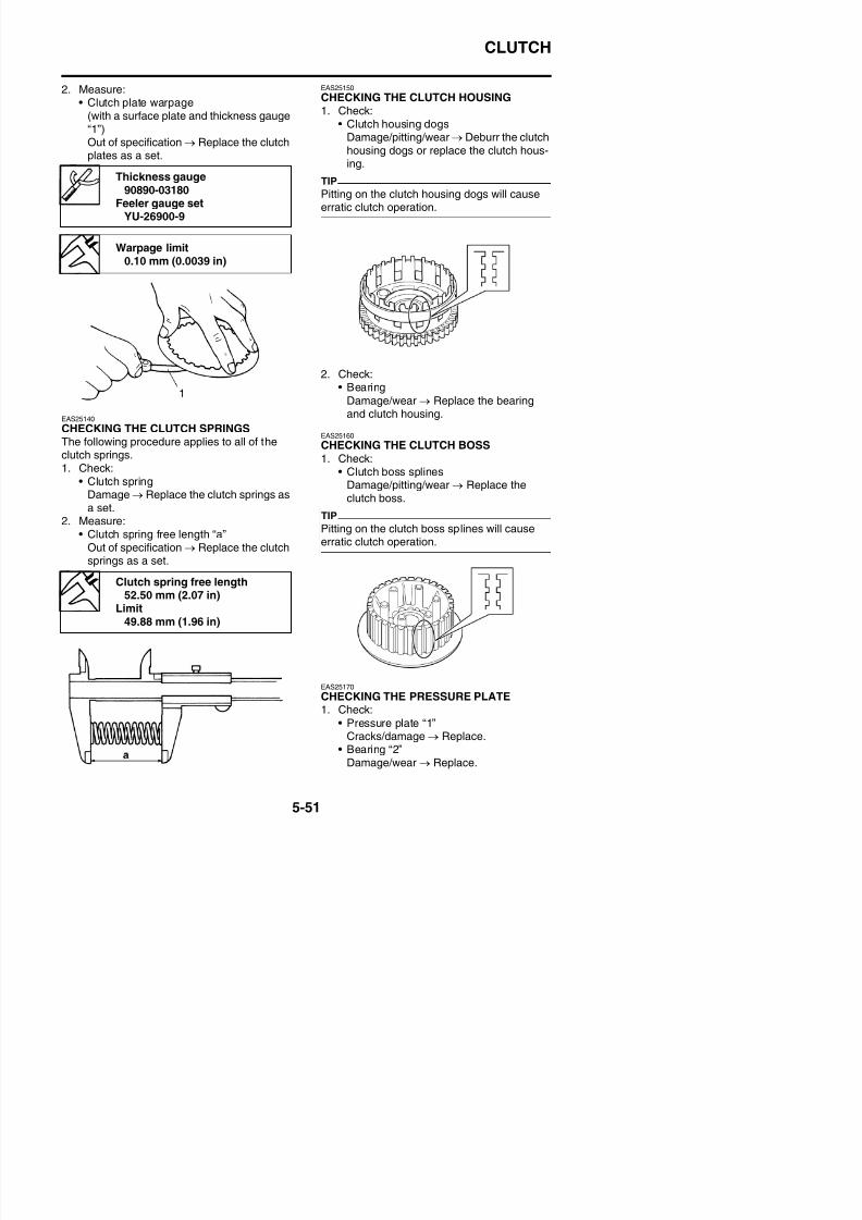
8/21/2019 Fz8 - Service Manual
http://slidepdf.com/reader/full/fz8-service-manual 316/609
• Clutch springDamage → Replace the clutch springs as
a set.2. Measure:
• Clutch spring free length “a”Out of specification → Replace the clutchsprings as a set.
Damage/pitting/wear → Replace theclutch boss.
TIP
Pitting on the clutch boss splines will causeerratic clutch operation.
Clutch spring free length52.50 mm (2.07 in)
Li i
CLUTCH
EAS25220
CHECKING THE PULL LEVER SHAFT ANDPULL ROD1. Check:
• Pull lever shaft pinion gear teeth “1”• Pull rod teeth “2”
Damage/wear → Replace the pull rodand pull lever shaft as a set.
2. Check:• Pull rod bearing
Damage/wear → Replace.
3. Install:• Wire circlip “1”
4. Install:• Clutch housing “1”
TIP
Make sure to fit the projections “a” of the oil/ water pump assembly drive sprocket to theconcave “b” of the clutch housing.
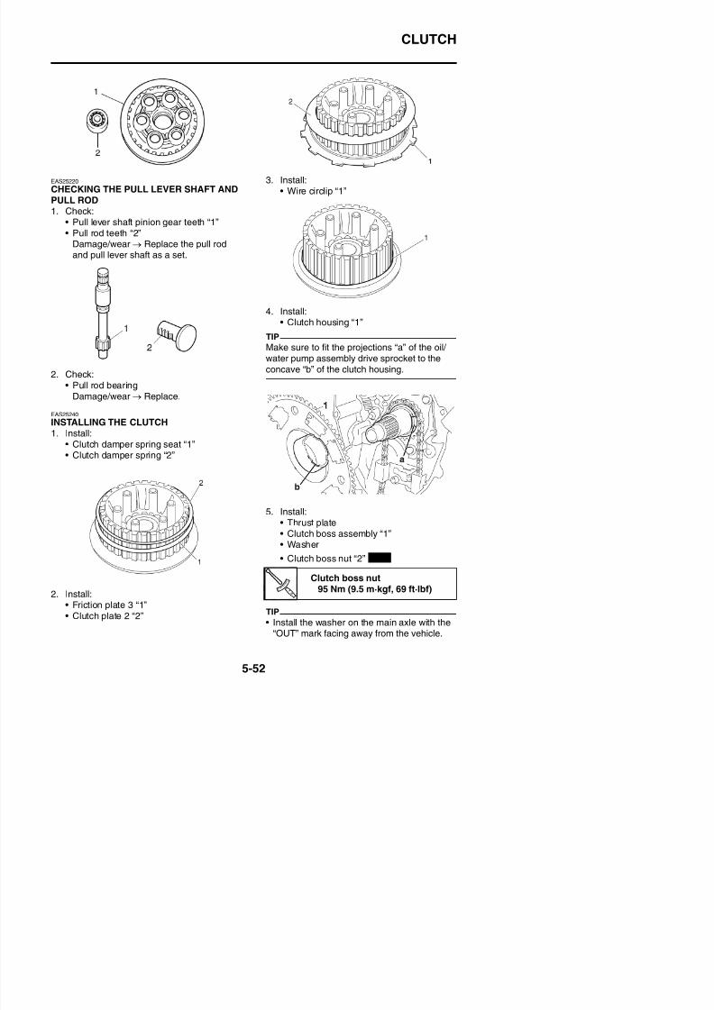
8/21/2019 Fz8 - Service Manual
http://slidepdf.com/reader/full/fz8-service-manual 317/609
Damage/wear → Replace.
EAS25240
INSTALLING THE CLUTCH1. Install:
• Clutch damper spring seat “1”• Clutch damper spring “2”
CLUTCH
• Stake the clutch boss nut at a cutout “a” inthe main axle.
• While holding the clutch boss assembly “1”with the universal clutch holder “3”, tightenthe clutch boss nut.
7. Install:• Friction plate 1 “1”
TIP
• Install the last friction plate shifting halfphase.
• Assemble friction plate 1 to the clutch bossassembly so that red paint marks “a” on fric-
tion plate 1 is aligned with red paint mark “b”of friction plates 2 and 3 as shown in theillustration.
Universal clutch holder
90890-04086YM-91042
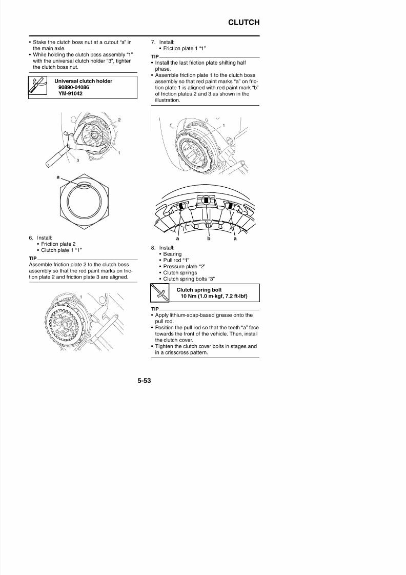
8/21/2019 Fz8 - Service Manual
http://slidepdf.com/reader/full/fz8-service-manual 318/609
6. Install:• Friction plate 2• Clutch plate 1 “1”
TIP
Assemble friction plate 2 to the clutch bossassembly so that the red paint marks on fric-tion plate 2 and friction plate 3 are aligned.
8. Install:• Bearing• Pull rod “1”
• Pressure plate “2”• Clutch springs• Clutch spring bolts “3”
CLUTCH
9. Install:• Dowel pins
• Clutch cover gasket
• Clutch cover “1”
TIP
• Apply engine oil onto the bearing.• Apply locking agent (LOCTITE®) to the
threads of only the clutch cover bolts “a”shown in the illustration.
• Tighten the clutch cover bolts in stages andin a crisscross pattern.
11. Adjust:• Clutch cable free play
Refer to “ADJUSTING THE CLUTCHCABLE FREE PLAY” on page 3-13.
Clutch cover bolt12 Nm (1.2 m·kgf, 8.7 ft·lbf)
New
Clutch cable free play10.0–15.0 mm (0.39–0.59 in)
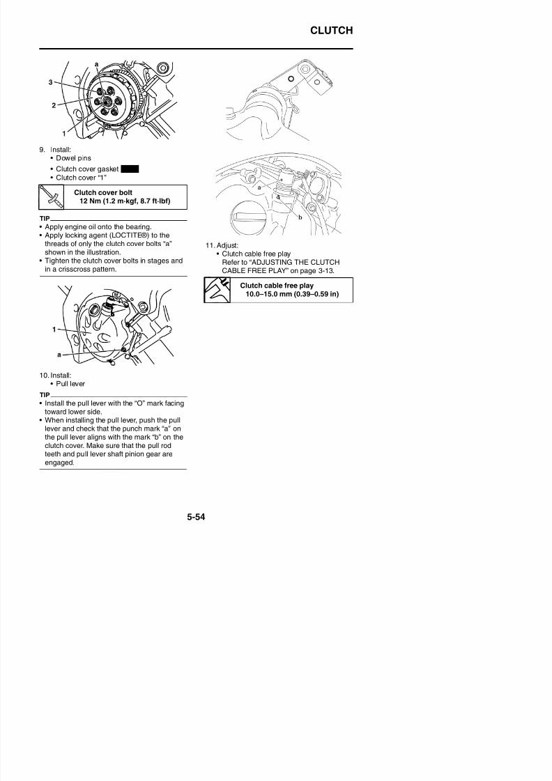
8/21/2019 Fz8 - Service Manual
http://slidepdf.com/reader/full/fz8-service-manual 319/609
10. Install:• Pull lever
SHIFT SHAFT
EAS25410
SHIFT SHAFT
Removing the shift shaft and stopper lever
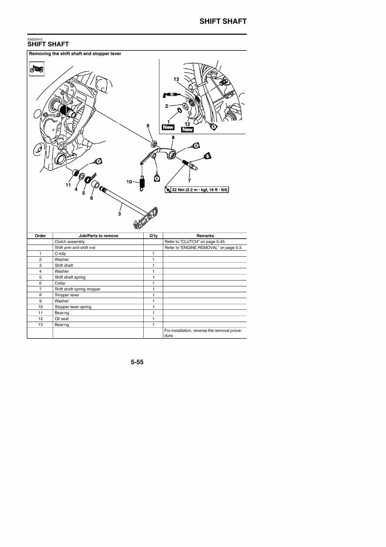
8/21/2019 Fz8 - Service Manual
http://slidepdf.com/reader/full/fz8-service-manual 320/609
Order Job/Parts to remove Q’ty Remarks
Clutch assembly Refer to “CLUTCH” on page 5-45.
Shift arm and shift rod Refer to “ENGINE REMOVAL” on page 5-3.
1 Circlip 1
2 Washer 1
3 Shift shaft 1
4 Washer 1
SHIFT SHAFT
EAS25420
CHECKING THE SHIFT SHAFT1. Check:
• Shift shaft “1”Bends/damage/wear → Replace.
• Shift shaft spring “2”• Collar “3”
Damage/wear → Replace.
EAS25430
CHECKING THE STOPPER LEVER1. Check:
• Stopper lever “1”Bends/damage → Replace.Roller turns roughly → Replace the stop-
per lever.
2. Install:• Bearing• Washer• Collar• Shift shaft spring “1”
• Shift shaft “2”
TIP
Hook the end of the shift shaft spring onto theshift shaft spring stopper.
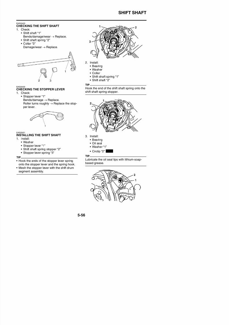
8/21/2019 Fz8 - Service Manual
http://slidepdf.com/reader/full/fz8-service-manual 321/609
EAS25451
INSTALLING THE SHIFT SHAFT1. Install:
• Washer• Stopper lever “1”• Shift shaft spring stopper “2”• Stopper lever spring “3”
TIP
• Hook the ends of the stopper lever spring
3. Install:• Bearing• Oil seal• Washer “1”
• Circlip “2”
TIP
Lubricate the oil seal lips with lithium-soap-
New
OIL PUMP
EAS24921
OIL PUMP
Removing the oil pan and oil pump
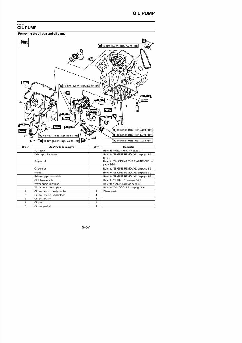
8/21/2019 Fz8 - Service Manual
http://slidepdf.com/reader/full/fz8-service-manual 322/609
Order Job/Parts to remove Q’ty Remarks
Fuel tank Refer to “FUEL TANK” on page 7-1.
Drive sprocket cover Refer to “ENGINE REMOVAL” on page 5-3.
Engine oil
Drain.
Refer to “CHANGING THE ENGINE OIL” onpage 3-24.
O2 sensor Refer to “ENGINE REMOVAL” on page 5-3.
OIL PUMP
Removing the oil pan and oil pump
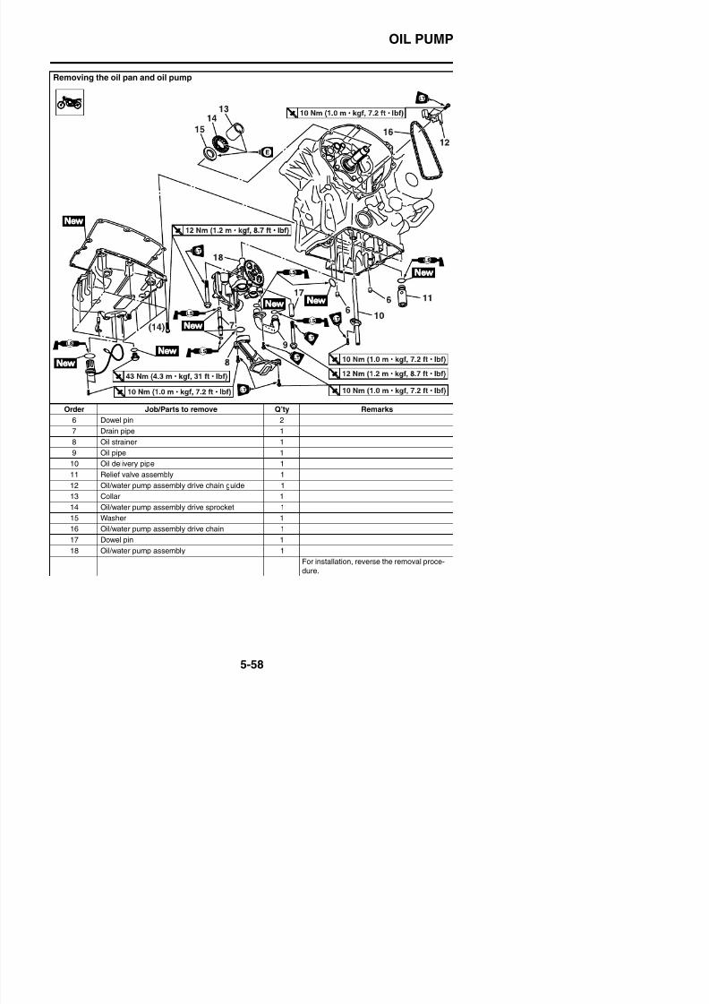
8/21/2019 Fz8 - Service Manual
http://slidepdf.com/reader/full/fz8-service-manual 323/609
Order Job/Parts to remove Q’ty Remarks
6 Dowel pin 27 Drain pipe 1
8 Oil strainer 1
9 Oil pipe 1
10 Oil delivery pipe 1
11 Relief valve assembly 1
12 Oil/water pump assembly drive chain guide 1
13 Collar 1
OIL PUMP
Disassembling the oil pump
Order Job/Parts to remove Q’ty Remarks
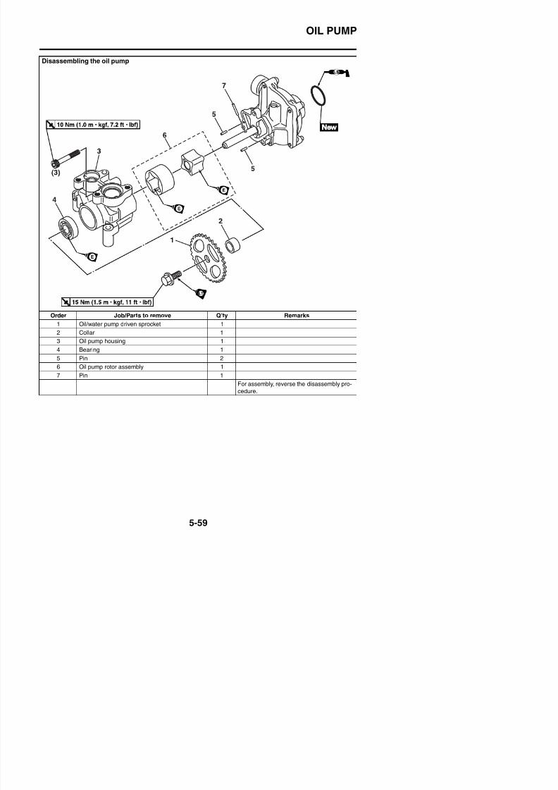
8/21/2019 Fz8 - Service Manual
http://slidepdf.com/reader/full/fz8-service-manual 324/609
1 Oil/water pump driven sprocket 1
2 Collar 1
3 Oil pump housing 1
4 Bearing 1
5 Pin 2
6 Oil pump rotor assembly 1
7 Pin 1
For assembly, reverse the disassembly pro-
cedure
OIL PUMP
EAS24930
REMOVING THE OIL PAN1. Remove:
• Oil level switch “1”• Oil pan “2”• Oil pan gasket• Dowel pins
TIP
Loosen each bolt 1/4 of a turn at a time, instages and in a crisscross pattern. After all ofthe bolts are fully loosened, remove them.
EAS25620
CHECKING THE SPROCKET AND CHAIN
1. Check:• Oil/water pump assembly drive sprocket
“1”Cracks/damage/wear → Replace.
EAS24960
CHECKING THE OIL PUMP1. Check:
• Oil pump driven gear “1”• Oil pump housing “2”
Cracks/damage/wear → Replace thedefective part(s).
2. Measure:• Inner-rotor-to-outer-rotor-tip clearance “a”• Outer-rotor-to-oil-pump-housing clear-
ance “b”• Oil-pump-housing-to-inner-rotor-and-
outer-rotor clearance “c”Out of specification → Replace the defec-tive part(s).
Inner-rotor-to-outer-rotor-tipclearance
Less than 0.12 mm (0.0047 in)Limit
0.20 mm (0.0079 in)Outer-rotor-to-oil-pump-hous-ing clearance
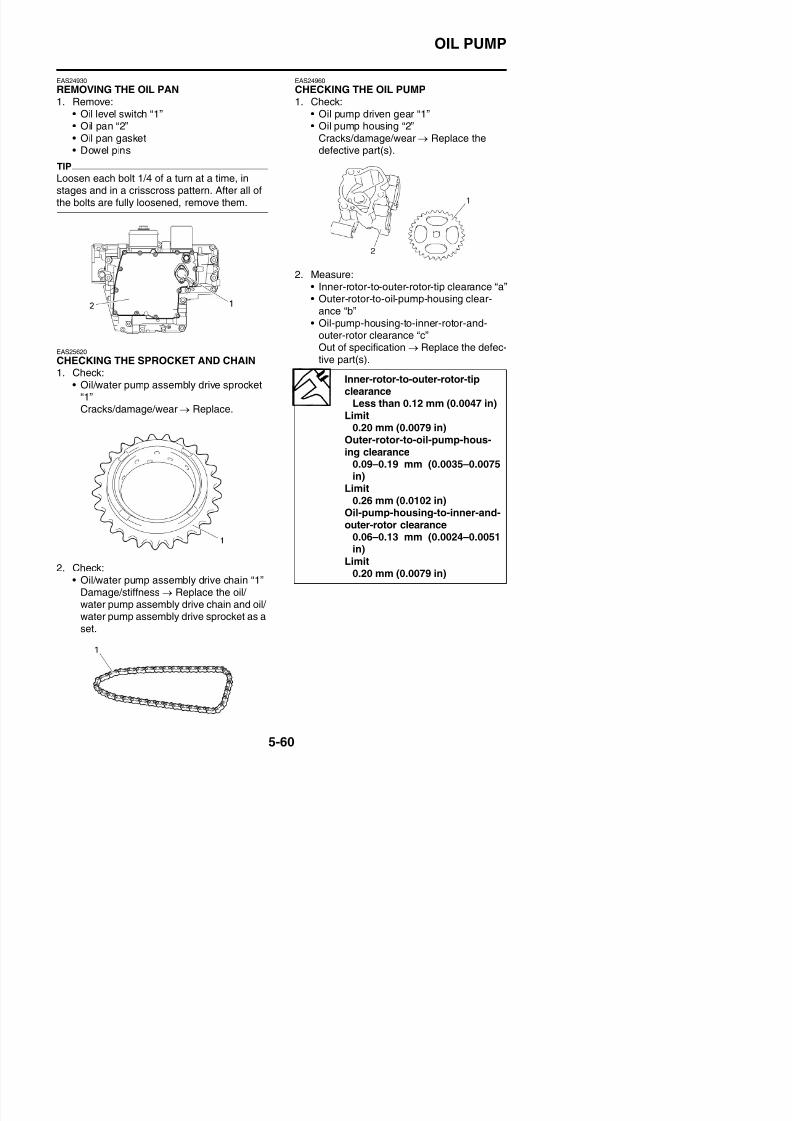
8/21/2019 Fz8 - Service Manual
http://slidepdf.com/reader/full/fz8-service-manual 325/609
ing clearance
0.09–0.19 mm (0.0035–0.0075in)Limit
0.26 mm (0.0102 in)Oil-pump-housing-to-inner-and-outer-rotor clearance
0.06–0.13 mm (0.0024–0.0051in)
OIL PUMP
3. Check:• Oil pump operation
Rough movement → Repeat steps (1)and (2) or replace the defective part(s).
EAS24980
CHECKING THE OIL DELIVERY PIPESThe following procedure applies to all of the oildelivery pipes.
1. Check:• Oil delivery pipe “1”
• Oil pipe “2”Damage → Replace.Obstruction → Wash and blow out withcompressed air.
EAS24990
CHECKING THE OIL STRAINER1. Check:
1. Inner rotor
2. Outer rotor
3. Oil pump housing
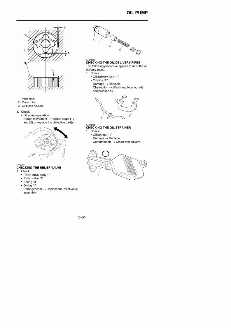
8/21/2019 Fz8 - Service Manual
http://slidepdf.com/reader/full/fz8-service-manual 326/609
• Oil strainer “1”
Damage → Replace.Contaminants → Clean with solvent.
OIL PUMP
EAS25010
ASSEMBLING THE OIL PUMP1. Lubricate:
• Inner rotor• Outer rotor• Oil pump shaft
(with the recommended lubricant)
2. Install:• Pin “1”• Inner rotor “2”• Outer rotor “3”• Oil pump housing “4”• Oil pump housing bolt
TIP
When installing the inner rotor, align the pin “1”in the oil pump shaft with the groove “a” in theinner rotor “2”.
4. Check:• Oil pump operation
Refer to “CHECKING THE OIL PUMP” onpage 5-60.
EAS25030
INSTALLING THE OIL/WATER PUMP1. Install:
• O-ring
• Oil/water pump assembly “1”• Dowel pin
• Bolts “2”
Recommended lubricantEngine oil
Oil pump housing bolt10 Nm (1.0 m·kgf, 7.2 ft·lbf)
Oil/water pump assembly bolt
12 Nm (1.2 m·kgf, 8.7 ft·lbf)LOCTITE®
New
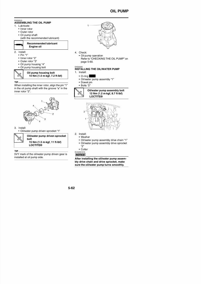
8/21/2019 Fz8 - Service Manual
http://slidepdf.com/reader/full/fz8-service-manual 327/609
3. Install:• Oil/water pump driven sprocket “1”
2. Install:• Washer• Oil/water pump assembly drive chain “1”
Oil/water pump driven sprocketbolt
OIL PUMP
TIP
Install the oil/water pump assembly drive chain“1” onto the oil/water pump assembly drivesprocket “2”.
3. Install:• Oil/water pump assembly drive chain
guide “1”
TIP
“UP” mark of the oil/water pump assemblydrive chain guide is upward.
5. Install:• Relief valve assembly “1”
• O-ring
• Oil strainer “2”
• O-ring
• Oil pipe “3”
• O-rings
• Drain pipe “4”
• O-rings
Oil/water pump assembly drive
chain guide bolt10 Nm (1.0 m·kgf, 7.2 ft·lbf)
LOCTITE®
Oil strainer bolt10 Nm (1.0 m·kgf, 7.2 ft·lbf)LOCTITE®
Oil pipe bolt
10 Nm (1.0 m·kgf, 7.2 ft·lbf)LOCTITE®
New
New
New
New
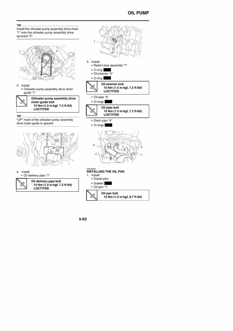
8/21/2019 Fz8 - Service Manual
http://slidepdf.com/reader/full/fz8-service-manual 328/609
OIL PUMP
• Oil level switch “2”
• Engine oil drain bolt “3”
WARNING
EWA12820
Always use new copper washers.
TIP
• Tighten the oil pan bolts in stages and in acrisscross pattern.
• Lubricate the oil level switch O-ring with lith-ium-soap-based grease.
Oil level switch bolt10 Nm (1.0 m·kgf, 7.2 ft·lbf)
Engine oil drain bolt43 Nm (4.3 m·kgf, 31 ft·lbf)
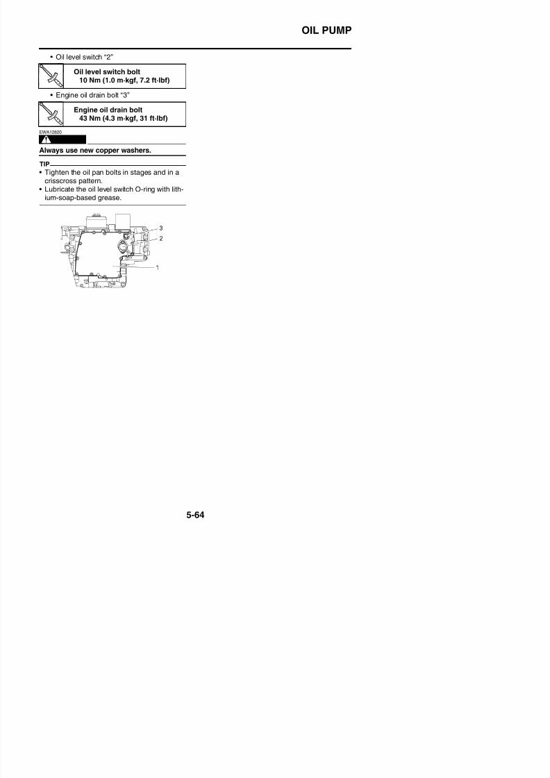
8/21/2019 Fz8 - Service Manual
http://slidepdf.com/reader/full/fz8-service-manual 329/609
CRANKCASE
EAS25540
CRANKCASE
Separating the crankcase
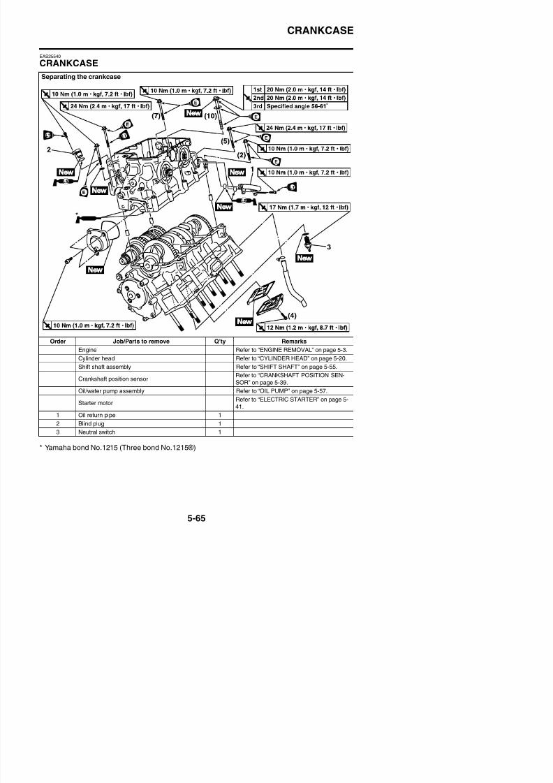
8/21/2019 Fz8 - Service Manual
http://slidepdf.com/reader/full/fz8-service-manual 330/609
Order Job/Parts to remove Q’ty Remarks
Engine Refer to “ENGINE REMOVAL” on page 5-3.
Cylinder head Refer to “CYLINDER HEAD” on page 5-20.
Shift shaft assembly Refer to “SHIFT SHAFT” on page 5-55.
Crankshaft position sensorRefer to “CRANKSHAFT POSITION SEN-
SOR” on page 5-39.
CRANKCASE
Separating the crankcase
O d J b/P t t Q’t R k
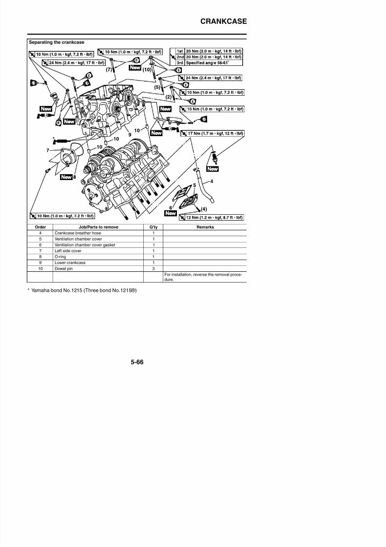
8/21/2019 Fz8 - Service Manual
http://slidepdf.com/reader/full/fz8-service-manual 331/609
Order Job/Parts to remove Q’ty Remarks
4 Crankcase breather hose 1
5 Ventilation chamber cover 1
6 Ventilation chamber cover gasket 1
7 Left side cover 1
8 O-ring 1
9 Lower crankcase 1
10 Dowel pin 3
CRANKCASE
EAS25550DISASSEMBLING THE CRANKCASE1. Place the engine upside down.2. Remove:
• Crankcase bolts
TIP
• Loosen each bolt 1/4 of a turn at a time, in
stages and in a crisscross pattern. After all of
the bolts are fully loosened, remove them.• Loosen the bolts in decreasing numerical
order (refer to the numbers in the illustration).• The numbers embossed on the crankcase
indicate the crankcase tightening sequence.
3. Remove:• Lower crankcase
ECA13900
EAS25580CHECKING THE CRANKCASE1. Thoroughly wash the crankcase halves in a
mild solvent.2. Thoroughly clean all the gasket surfaces
and crankcase mating surfaces.3. Check:
• Crankcase
Cracks/damage→
Replace.• Oil delivery passagesObstruction → Blow out with compressedair.
EAS25650
ASSEMBLING THE CRANKCASE1. Lubricate:
• Crankshaft journal bearing inner surface
(with the recommended lubricant)
2. Apply:• Sealant
(onto the crankcase mating surfaces)
TIP
• Do not allow any sealant to come into con-tact with the oil gallery or crankshaft journalbearings. Do not apply sealant to within 2–3
Recommended lubricantEngine oil
Yamaha bond No.1215(Three bond No.1215®)90890-85505
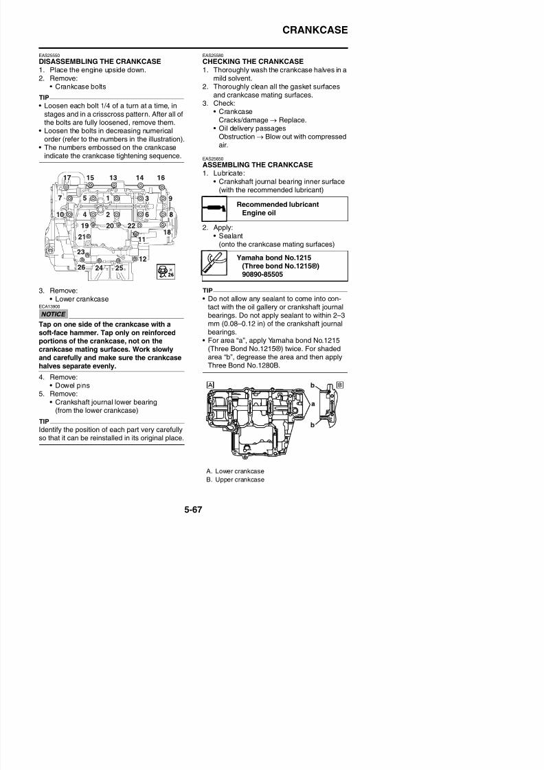
8/21/2019 Fz8 - Service Manual
http://slidepdf.com/reader/full/fz8-service-manual 332/609
Tap on one side of the crankcase with asoft-face hammer. Tap only on reinforcedportions of the crankcase, not on thecrankcase mating surfaces. Work slowlyand carefully and make sure the crankcasehalves separate evenly.
4. Remove:
g pp y
mm (0.08–0.12 in) of the crankshaft journalbearings.
• For area “a”, apply Yamaha bond No.1215(Three Bond No.1215®) twice. For shadedarea “b”, degrease the area and then applyThree Bond No.1280B.
CRANKCASE
3. Install:• Dowel pins
4. Set the shift drum assembly and transmis-sion gears in the neutral position.
5. Install:• Lower crankcase “1”
(onto the upper crankcase “2”)ECA13980
Before tightening the crankcase bolts,make sure the transmission gears shift cor-rectly when the shift drum assembly isturned by hand.
6. Install:• Crankcase bolts
TIP
• Lubricate the bolts “1”–“10” thread, matingsurfaces and washers with engine oil.
• Lubricate the bolts “11”–“26” thread and mat-ing surfaces with engine oil (except “11”).
• Apply LOCTITE® to the screw of the bolt
* Following the tightening order, loosen thebolt one by one and then retighten it to thespecific torque.
Crankcase bolt “1”–“10”1st: 20 Nm (2.0 m·kgf, 14 ft·lbf)2nd*: 20 Nm (2.0 m·kgf, 14ft·lbf)3rd: 56°–61°
Crankcase bolt “11”–“16”24 Nm (2.4 m·kgf, 17 ft·lbf)
Crankcase bolt “17”–“26”10 Nm (1.0 m·kgf, 7.2 ft·lbf)
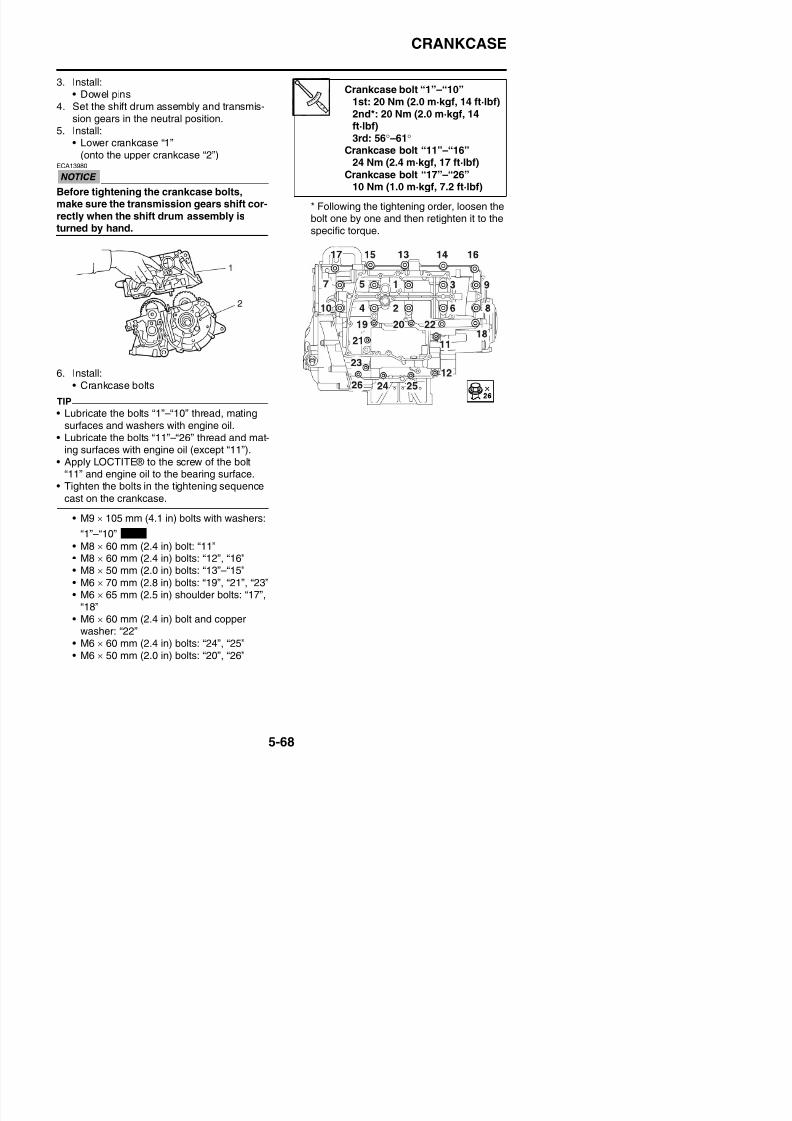
8/21/2019 Fz8 - Service Manual
http://slidepdf.com/reader/full/fz8-service-manual 333/609
pp y OC ® to t e sc e o t e bo t
“11” and engine oil to the bearing surface.• Tighten the bolts in the tightening sequence
cast on the crankcase.
• M9 × 105 mm (4.1 in) bolts with washers:
“1”–“10”
• M8 × 60 mm (2.4 in) bolt: “11”M8 60 (2 4 i ) b lt “12” “16”
New
CONNECTING RODS AND PISTONS
EAS39P1503
CONNECTING RODS AND PISTONS
Removing the connecting rods and pistons
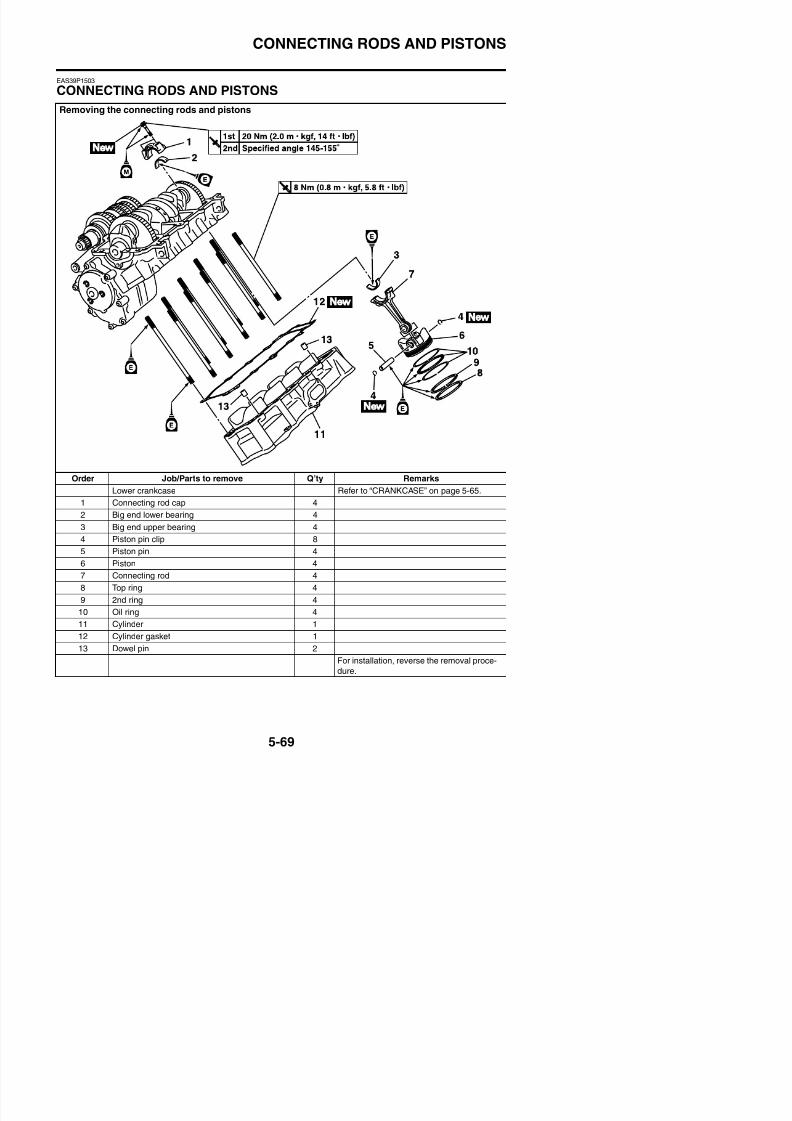
8/21/2019 Fz8 - Service Manual
http://slidepdf.com/reader/full/fz8-service-manual 334/609
Order Job/Parts to remove Q’ty Remarks
Lower crankcase Refer to “CRANKCASE” on page 5-65.
1 Connecting rod cap 4
2 Big end lower bearing 4
3 Big end upper bearing 4
4 Piston pin clip 8
5 Piston pin 4
CONNECTING RODS AND PISTONS
EAS26030REMOVING THE CONNECTING RODS ANDPISTONSThe following procedure applies to all of theconnecting rods and pistons.1. Remove:
• Connecting rod cap “1”• Connecting rod
• Big end bearingsTIP
• Identify the position of each big end bearingso that it can be reinstalled in its originalplace.
• After removing the connecting rods and con-necting rod caps, care should be taken not todamage the mating surfaces of the connect-
ing rods and connecting rod caps.
2. Remove:• Piston pin clips “1”• Piston pin “2”
3. Remove:• Top ring• 2nd ring• Oil ring
TIP
When removing a piston ring, open the endgap with your fingers and lift the other side ofthe ring over the piston crown.
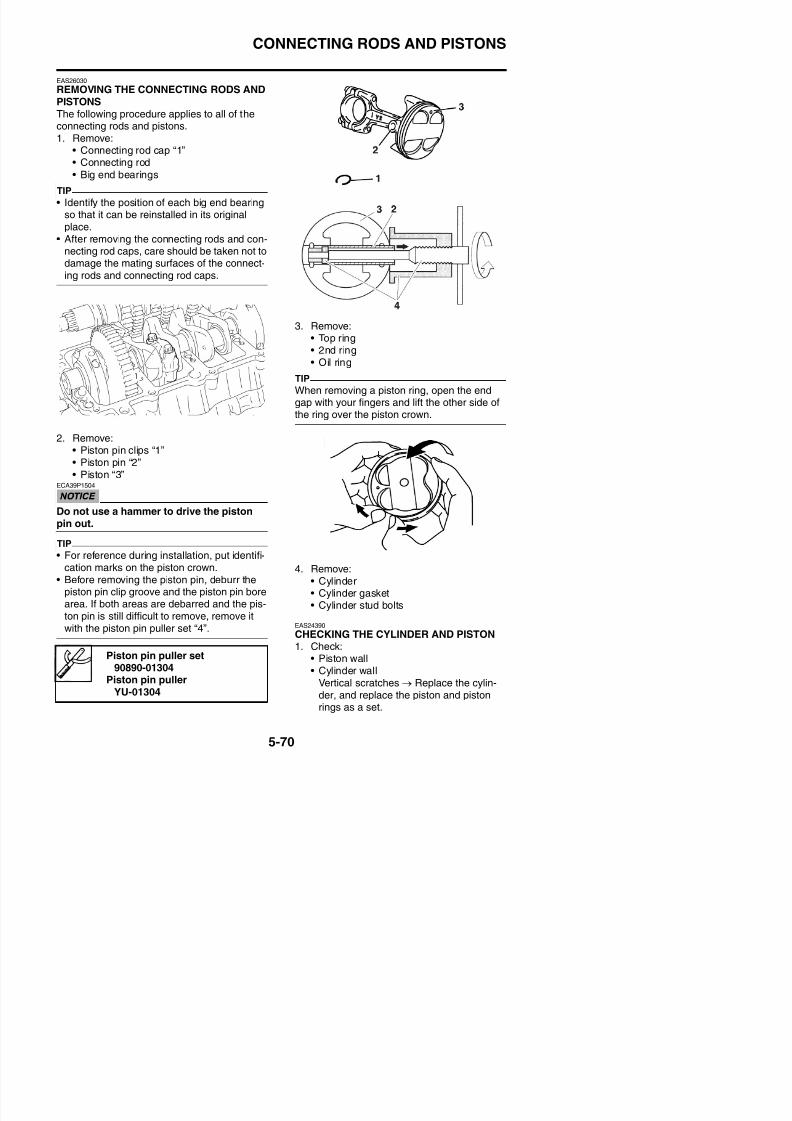
8/21/2019 Fz8 - Service Manual
http://slidepdf.com/reader/full/fz8-service-manual 335/609
• Piston “3”ECA39P1504
Do not use a hammer to drive the pistonpin out.
TIP
• For reference during installation put identifi
CONNECTING RODS AND PISTONS
2. Measure:• Piston-to-cylinder clearance
a. Measure cylinder bore “C” with the cylinderbore gauge.
TIP
Measure cylinder bore “C” by taking side-to-side and front-to-back measurements of the
cylinder. Then, find the average of the mea-surements.
d. If out of specification, replace the pistonand piston rings as a set.
e. Calculate the piston-to-cylinder clearancewith the following formula.
f. If out of specification, replace the cylinder,and replace the piston and piston rings asa set.
Bore68.000–68.010 mm (2.6772–2.6776 in)
Taper limit0.050 mm (0.0020 in)
Out of round limit0.050 mm (0.0020 in)
“C” = maximum of D1–D6
Taper limit = maximum of D1 or D2 – maxi-
mum of D5 or D6
Out of round limit = maximum of D1, D3 or D5
- minimum of D2, D4 or D6
a. 11.5 mm (0.45 in) from the bottom edge ofthe piston
Piston-to-cylinder clearance = Cylinder bore“C” - Piston skirt diameter “P”
Piston-to-cylinder clearance0.010–0.035 mm (0.0004–0.0014 in)
Limit0.150 mm (0.0059 in)
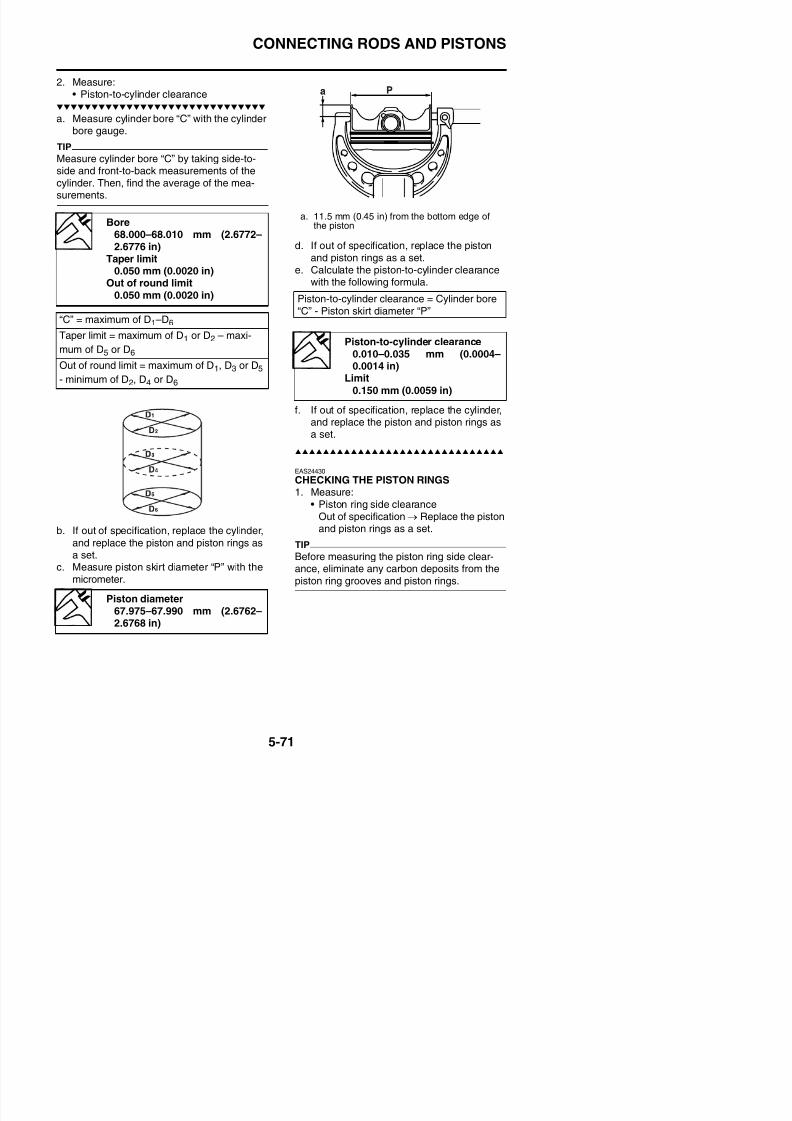
8/21/2019 Fz8 - Service Manual
http://slidepdf.com/reader/full/fz8-service-manual 336/609
b. If out of specification, replace the cylinder,
and replace the piston and piston rings asa set
EAS24430CHECKING THE PISTON RINGS1. Measure:
• Piston ring side clearanceOut of specification → Replace the pistonand piston rings as a set.
TIP
Before measuring the piston ring side clear
CONNECTING RODS AND PISTONS
2. Install:
• Piston ring(into the cylinder)
TIP
Level the piston ring into the cylinder with thepiston crown.
3. Measure:• Piston ring end gap
EAS24440
CHECKING THE PISTON PINThe following procedure applies to all of the
piston pins.1. Check:
Piston ring side clearanceTop ring
0.030–0.065 mm (0.0012–0.0026 in)
Limit0.115 mm (0.0045 in)
2nd ring
0.020–0.055 mm (0.0008–0.0022 in)Limit
0.115 mm (0.0045 in)
Piston ring end gapTop ring
0.25–0.35 mm (0.0098–0.0138in)
Limit0.60 mm (0.0236 in)
2nd ring
0.35–0.50 mm (0.0138–0.0197in)Limit
0.85 mm (0.0335 in)Oil ring
0.10–0.35 mm (0.0039–0.0138in)
a. 5 mm (0.20 in)
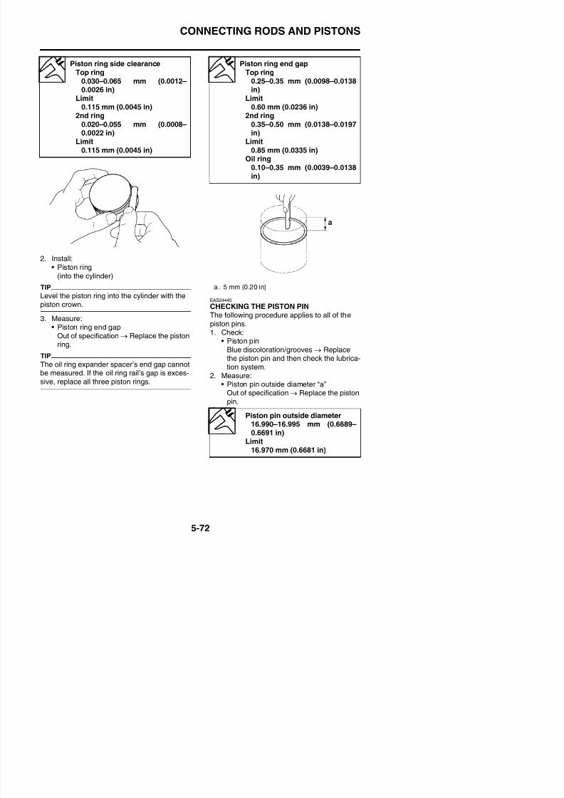
8/21/2019 Fz8 - Service Manual
http://slidepdf.com/reader/full/fz8-service-manual 337/609
Out of specification → Replace the pistonring.
TIP
The oil ring expander spacer’s end gap cannotbe measured. If the oil ring rail’s gap is exces-sive, replace all three piston rings.
• Piston pinBlue discoloration/grooves → Replacethe piston pin and then check the lubrica-tion system.
2. Measure:• Piston pin outside diameter “a”
Out of specification → Replace the piston
CONNECTING RODS AND PISTONS
3. Measure:• Piston pin bore inside diameter “b”
Out of specification → Replace the pis-ton.
EAS39P1504CHECKING THE CONNECTING RODS1. Measure:
• Crankshaft-pin-to-big-end-bearing clear-anceOut of specification → Replace the bigend bearings.
The following procedure applies to all of the
connecting rods.ECA13930
Do not interchange the big end bearingsand connecting rods. To obtain the correct
crankshaft-pin-to-big-end-bearing clear-ance and prevent engine damage, the bigend bearings must be installed in their orig-
inal positions.a. Clean the big end bearings, crankshaft
pins, and the inside of the connecting rodshalves.
b. Install the big end upper bearing into theconnecting rod and the big end lower bear-ing into the connecting rod cap.
TIP
Piston pin bore inside diameter17.002–17.013 mm (0.6694–0.6698 in)
Limit17.043 mm (0.6710 in)
Crankshaft-pin-to-big-end-bear-
ing clearance0.034–0.058 mm (0.0013–0.0023 in)
Limit0.09 mm (0.0035 in)
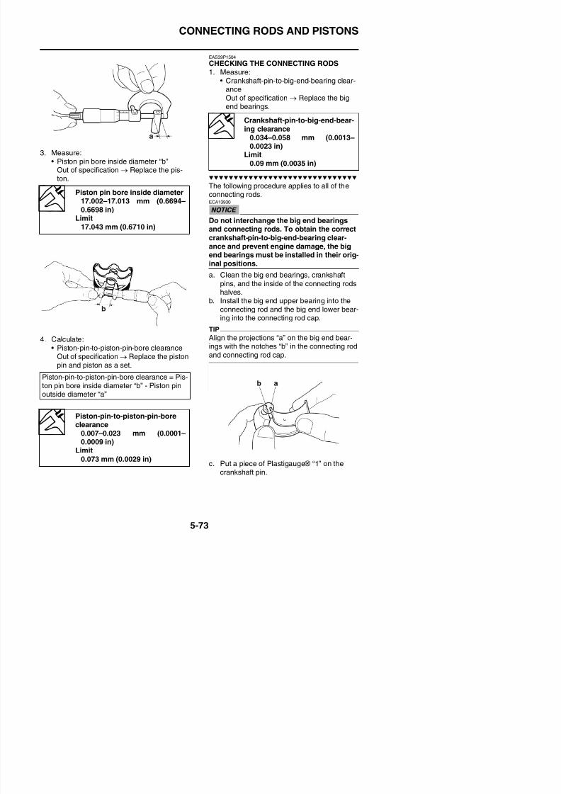
8/21/2019 Fz8 - Service Manual
http://slidepdf.com/reader/full/fz8-service-manual 338/609
4. Calculate:• Piston-pin-to-piston-pin-bore clearance
Out of specification → Replace the pistonpin and piston as a set.
Align the projections “a” on the big end bear-ings with the notches “b” in the connecting rodand connecting rod cap.
Piston-pin-to-piston-pin-bore clearance = Pis-ton pin bore inside diameter “b” - Piston pinoutside diameter “a”
CONNECTING RODS AND PISTONS
d. Assemble the connecting rod halves.ECA39P1501
Tighten the connecting rod bolts using theplastic-region tightening angle method.Always install new bolts.
TIP
• Clean the connecting rod bolts and lubricatethe bolt threads and seats with molybdenumdisulfide oil.
• Make sure that the projection “a” on the con-necting rod cap faces the same direction asthe “Y” mark “b” on the connecting rod.
• After installing the big end bearing, assemblethe connecting rod and connecting rod capwithout installing them onto the crankshaft.
TIP
To install the big end bearing, care should betaken not to install it at an angle and the posi-tion should not be out of alignment.
f. Loosen the connecting rod bolt, remove theconnecting rod and connecting rod cap andinstall these parts to the crankshaft with thebig end bearing kept in the current condi-tion.
TIP
• Do not move the connecting rod or crank-shaft until the clearance measurement hasbeen completed.
• Make sure that the projection “a” on the con-necting rod cap faces the same direction asthe “Y” mark “b” on the connecting rod.
• Make sure the “Y” marks “b” on the connect-
ing rods face towards the left side of the
a. Side machined face
b. Thrusting faces
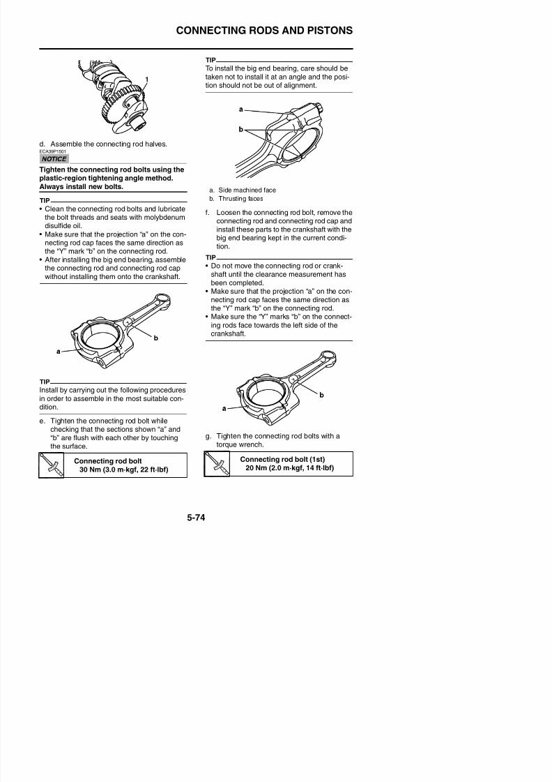
8/21/2019 Fz8 - Service Manual
http://slidepdf.com/reader/full/fz8-service-manual 339/609
TIP
I ll b i h f ll i d
crankshaft.
CONNECTING RODS AND PISTONS
h. Put a mark “1” on the corner of the con-necting rod bolt “2” and the connecting rodcap “3”.
i. Tighten the connecting rod bolts further toreach the specified angle 145°–155°.
WARNING
EWA13400
If the connecting rod bolt is tightened more
th th ifi d l d t l th
k. Remove the connecting rod and big endbearings.
l. Measure the compressed Plastigauge®width on the crankshaft pin. If the crank-shaft-pin-to-big-end-bearing clearance isout of specification, select replacement bigend bearings.
2. Select:• Big end bearings (P1–P4)
TIP
• The numbers “A” stamped into the crank-shaft web and the numbers “1” on the con-
necting rods are used to determine thereplacement big end bearings sizes.
• “P1”–“P4” refer to the bearings shown in the
crankshaft illustration.
For example, if the connecting rod “P1” and
the crankshaft web “P1” numbers are “5”
and “2” respectively, then the bearing size
f “P ” i
Connecting rod bolt (final)Specified angle 145°–155°
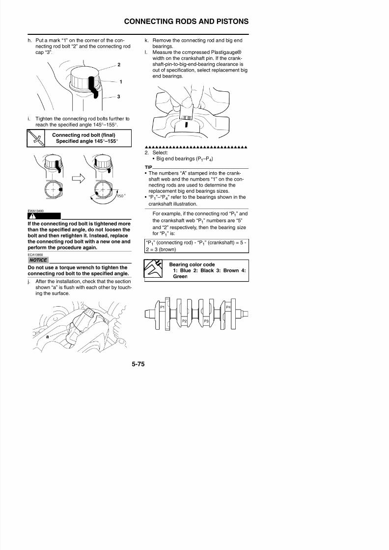
8/21/2019 Fz8 - Service Manual
http://slidepdf.com/reader/full/fz8-service-manual 340/609
than the specified angle, do not loosen thebolt and then retighten it. Instead, replacethe connecting rod bolt with a new one andperform the procedure again.
ECA13950
Do not use a torque wrench to tighten theconnecting rod bolt to the specified angle
for “P1” is:
“P1” (connecting rod) - “P1” (crankshaft) = 5 -
2 = 3 (brown)
Bearing color code1: Blue 2: Black 3: Brown 4:
CONNECTING RODS AND PISTONS
EAS26190
INSTALLING THE CONNECTING ROD ANDPISTONThe following procedure applies to all of the
connecting rods and pistons.1. Install:
• Big end bearings• Connecting rod cap
(onto the connecting rod)
TIP
• Be sure to reinstall each big end bearing inits original place.Ali th j ti “ ” th bi d b
2. Tighten:
• Connecting rod boltsECA14B1042
Tighten the connecting rod bolts using the
plastic-region tightening angle method.Always install new bolts.
TIP
Install by carrying out the following proceduresin order to assemble in the most suitable con-dition.
a. Replace the connecting rod bolts with newones.
b. Clean the connecting rod bolts and lubri-cate the bolt threads and seats with molyb-denum disulfide oil.
c. After installing the big end bearing, assem-ble the connecting rod and connecting rodcap without installing them onto the crank-
shaft
New
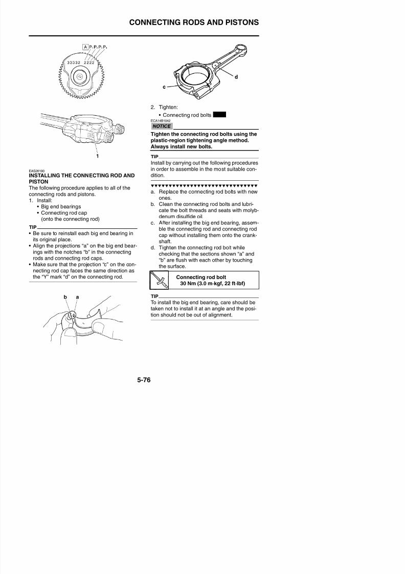
8/21/2019 Fz8 - Service Manual
http://slidepdf.com/reader/full/fz8-service-manual 341/609
• Align the projections “a” on the big end bear-ings with the notches “b” in the connectingrods and connecting rod caps.
• Make sure that the projection “c” on the con-necting rod cap faces the same direction asthe “Y” mark “d” on the connecting rod.
shaft.d. Tighten the connecting rod bolt while
checking that the sections shown “a” and“b” are flush with each other by touchingthe surface.
Connecting rod bolt30 Nm (3.0 m·kgf, 22 ft·lbf)
CONNECTING RODS AND PISTONS
e. Loosen the connecting rod bolt, remove theconnecting rod and connecting rod cap andinstall these parts to the crankshaft with the
big end bearing kept in the current condi-tion.
3. Install:• Oil ring expander “1”• Lower oil ring rail “2”• Upper oil ring rail “3”
• 2nd ring “4”• Top ring “5”(into the piston)
TIP
Be sure to install the piston rings so that the
manufacturer’s marks or numbers “a” face up.
• Install the piston pin clips, so that the clipends are 3 mm (0.12 in) “c” or more from thecutout in the piston.
• Reinstall each piston into its original cylinder.
5. Lubricate:• Piston• Piston rings• Cylinder
(with the recommended lubricant)
a. Side machined face
b. Thrusting faces
Recommended lubricant
Engine oil
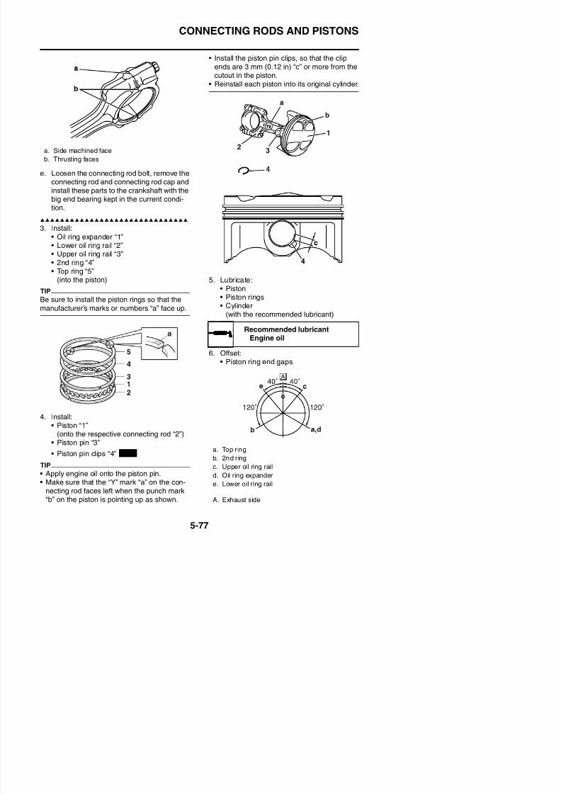
8/21/2019 Fz8 - Service Manual
http://slidepdf.com/reader/full/fz8-service-manual 342/609
6. Offset:• Piston ring end gaps
Engine oil
CONNECTING RODS AND PISTONS
7. Lubricate:• Crankshaft pins• Connecting rod big end bearing inner sur-
face(with the recommended lubricant)
8. Check:• Cylinder stud bolts
9. Install:• Piston assemblies “1”
(into the cylinder)TIP
While compressing the piston rings with onehand, install the connecting rod assembly intothe cylinder with the other hand.
10 Install
11. Tighten:• Connecting rod bolts “1”
TIPTighten the connecting rod bolts using the fol-lowing procedure.
a. Tighten the connecting rod bolts with a
torque wrench.
Recommended lubricantEngine oil
Cylinder stud bolt8 Nm (0.8 m·kgf, 5.8 ft·lbf)
Connecting rod bolt (1st)20 Nm (2.0 m·kgf, 14 ft·lbf)
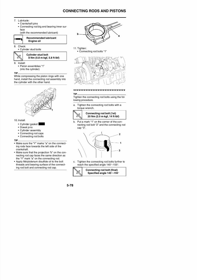
8/21/2019 Fz8 - Service Manual
http://slidepdf.com/reader/full/fz8-service-manual 343/609
10. Install:
• Cylinder gasket
• Dowel pins• Cylinder assembly• Connecting rod caps• Connecting rod bolts
b. Put a mark “1” on the corner of the con-necting rod bolt “2” and the connecting rodcap “3”.
New
CONNECTING RODS AND PISTONS
WARNING
EWA13400
If the connecting rod bolt is tightened morethan the specified angle, do not loosen thebolt and then retighten it. Instead, replacethe connecting rod bolt with a new one and
perform the procedure again.ECA13950
Do not use a torque wrench to tighten theconnecting rod bolt to the specified angle.
d. After the installation, check that the sectionshown “a” is flush with each other by touch-ing the surface.
WARNING
EWA39P1503
If the connecting rod and cap are not flush
with each other, remove the connecting rodbolts and big end bearing and restart fromstep (1). In this case, make sure to replacethe connecting rod bolts.
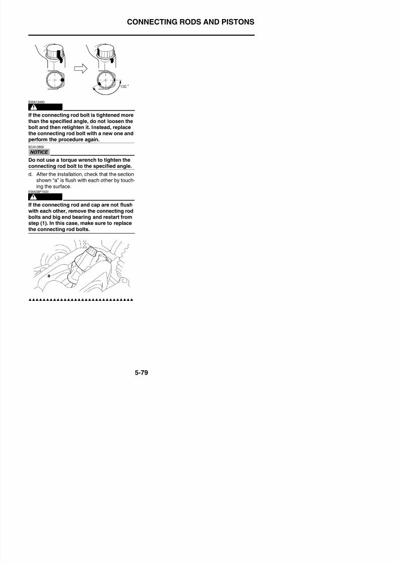
8/21/2019 Fz8 - Service Manual
http://slidepdf.com/reader/full/fz8-service-manual 344/609
CRANKSHAFT
EAS25950CRANKSHAFT
Removing the crankshaft
Order Job/Parts to remove Q’ty Remarks
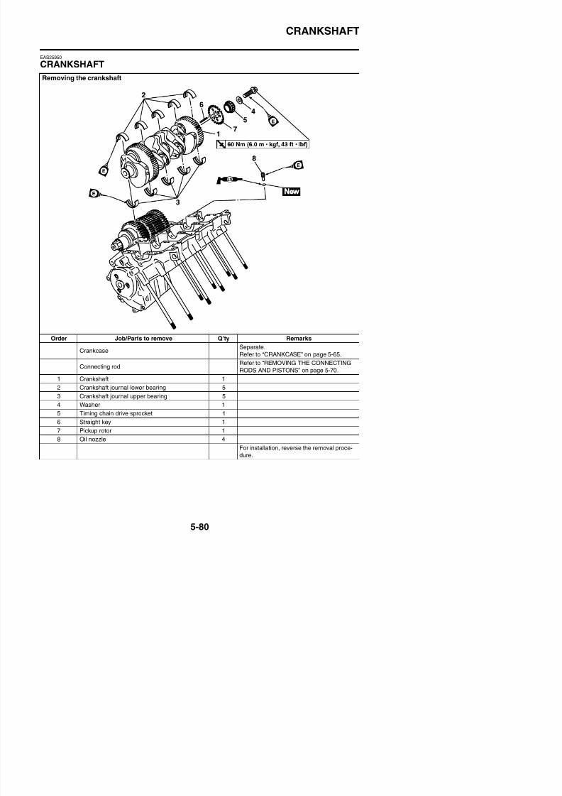
8/21/2019 Fz8 - Service Manual
http://slidepdf.com/reader/full/fz8-service-manual 345/609
y
CrankcaseSeparate.
Refer to “CRANKCASE” on page 5-65.
Connecting rodRefer to “REMOVING THE CONNECTING
RODS AND PISTONS” on page 5-70.
1 Crankshaft 1
2 Crankshaft journal lower bearing 5
3 C k h ft j l b i 5
CRANKSHAFT
EAS25980
REMOVING THE CRANKSHAFT ASSEMBLY1. Remove:
• Crankshaft assembly• Crankshaft journal bearings
TIP
Identify the position of each crankshaft journal
bearings so that it can be reinstalled in its orig-
inal place.
EAS14B1025
CHECKING THE OIL NOZZLESThe following procedure applies to all of the oil
nozzles.1. Check:
• Oil nozzle “1”
Damage/wear→
Replace the oil nozzle.• Oil passageObstruction → Blow out with compressedair.
EAS26071
CHECKING THE CRANKSHAFT1. Measure:
• Crankshaft runout
Out of specification → Replace the crank-shaft
2. Check:• Crankshaft journal surfaces• Crankshaft pin surfaces• Bearing surfaces
Scratches/wear → Replace the crank-shaft.
3. Measure:• Crankshaft-journal-to-crankshaft-journal-
bearing clearanceOut of specification → Replace the crank-shaft journal bearings.
ECA13920
Do not interchange the crankshaft journalbearings. To obtain the correct crankshaft-journal-to-crankshaft-journal-bearing clear-ance and prevent engine damage, thecrankshaft journal bearings must beinstalled in their original positions.
a. Clean the crankshaft journal bearings,crankshaft journals, and bearing portions ofthe crankcase.
b. Place the upper crankcase upside down ona bench.
c. Install the crankshaft journal upper bear-
ings “1” and the crankshaft into the uppercrankcase.
TIP
Journal oil clearance0.013–0.037 mm (0.0005–0.0015 in)
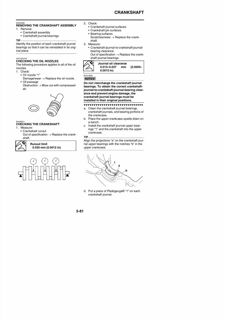
8/21/2019 Fz8 - Service Manual
http://slidepdf.com/reader/full/fz8-service-manual 346/609
p → pshaft. TIP
Align the projections “a” on the crankshaft jour-nal upper bearings with the notches “b” in theupper crankcase.
Runout limit0.030 mm (0.0012 in)
CRANKSHAFT
TIPDo not put the Plastigauge® over the oil hole inthe crankshaft journal.
e. Install the crankshaft journal lower bear-ings “1” into the lower crankcase and
assemble the crankcase halves.TIP
• Align the projections “a” of the crankshaft journal lower bearings with the notches “b” inthe lower crankcase.
• Do not move the crankshaft until the clear-ance measurement has been completed.
4. Select:
• Crankshaft journal bearings (J1–J5)
TIP
• The numbers “A” stamped into the crank-shaft web and the numbers “B” stamped intothe lower crankcase are used to determinethe replacement crankshaft journal bearingsizes.
• “J1”–“J5” refer to the bearings shown in the
crankshaft illustration.• If “J1”–“J5” are the same, use the same size
for all of the bearings.
For example, if the crankcase “J1” and
crankshaft web “J1” numbers are 6 and 2
respectively, then the bearing size for “J1”
is:
“J1” (crankcase) - “J1” (crankshaft web) = 6 -
2 = 4 (green)
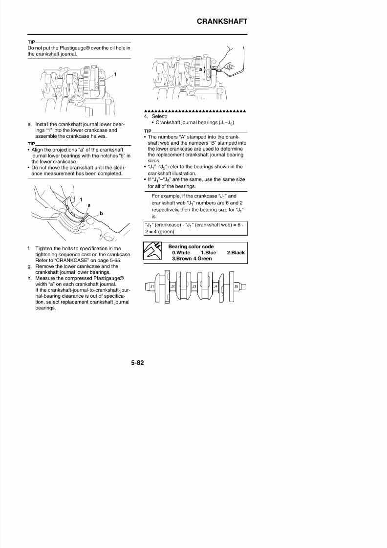
8/21/2019 Fz8 - Service Manual
http://slidepdf.com/reader/full/fz8-service-manual 347/609
f. Tighten the bolts to specification in thetightening sequence cast on the crankcase.Refer to “CRANKCASE” on page 5-65.
g. Remove the lower crankcase and thecrankshaft journal lower bearings
Bearing color code
0.White 1.Blue 2.Black 3.Brown 4.Green
CRANKSHAFT
EAS26200
INSTALLING THE CRANKSHAFT1. Install:
• Crankshaft journal upper bearings
(into the upper crankcase)• Crankshaft journal lower bearings
(into the lower crankcase)• Crankshaft
TIP
• Align the projections “a” on the crankshaft journal bearings “1” with the notches “b” inthe crankcase.
• Be sure to install each crankshaft journalb i i it i i l l
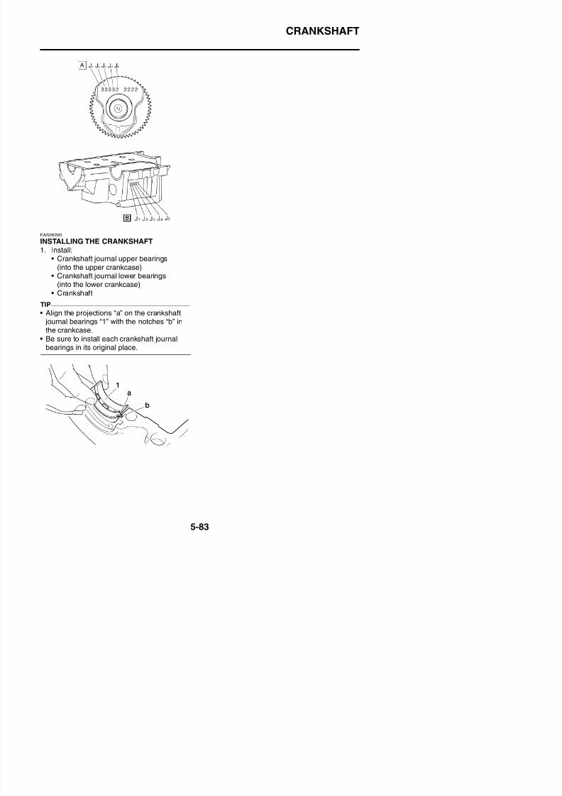
8/21/2019 Fz8 - Service Manual
http://slidepdf.com/reader/full/fz8-service-manual 348/609
bearings in its original place.
TRANSMISSION
EAS26241
TRANSMISSION
Removing the transmission, shift drum assembly, and shift forks
Order Job/Parts to remove Q’ty Remarks
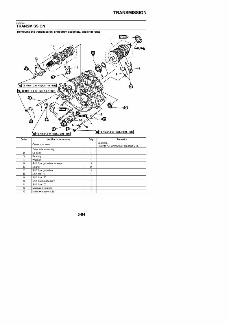
8/21/2019 Fz8 - Service Manual
http://slidepdf.com/reader/full/fz8-service-manual 349/609
Crankcase lowerSeparate.
Refer to “CRANKCASE” on page 5-65.
1 Drive axle assembly 1
2 Oil seal 1
3 Bearing 1
4 Washer 1
TRANSMISSION
Removing the transmission, shift drum assembly, and shift forks
Order Job/Parts to remove Q’ty Remarks
14 Oil pipe 1
15 Oil baffle plate 1
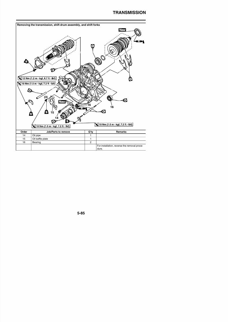
8/21/2019 Fz8 - Service Manual
http://slidepdf.com/reader/full/fz8-service-manual 350/609
16 Bearing 2
For installation, reverse the removal proce-
dure.
TRANSMISSION
Disassembling the main axle assembly
Order Job/Parts to remove Q’ty Remarks
1 2nd pinion gear 1
TIPWhen installing secondary pinion gear “1”,
install the gear with groove “a” facing to the
toothed lock washer.
2 T th d l k h 1
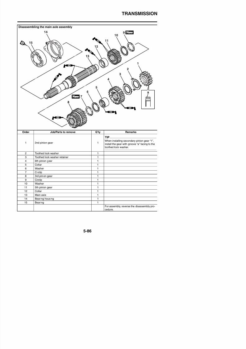
8/21/2019 Fz8 - Service Manual
http://slidepdf.com/reader/full/fz8-service-manual 351/609
2 Toothed lock washer 1
3 Toothed lock washer retainer 1
4 6th pinion gear 1
5 Collar 1
6 Washer 1
7 Circlip 1
TRANSMISSION
Disassembling the drive axle assembly
Order Job/Parts to remove Q’ty Remarks
1 Washer 1
2 1st wheel gear 1
3 Collar 14 5th wheel gear 1
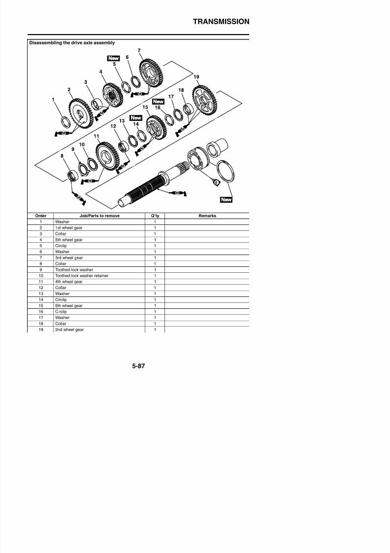
8/21/2019 Fz8 - Service Manual
http://slidepdf.com/reader/full/fz8-service-manual 352/609
5 Circlip 1
6 Washer 1
7 3rd wheel gear 1
8 Collar 1
9 Toothed lock washer 1
TRANSMISSION
Disassembling the drive axle assembly
Order Job/Parts to remove Q’ty Remarks
20 Collar 1
21 Bearing 1
22 Circlip 123 Drive axle 1
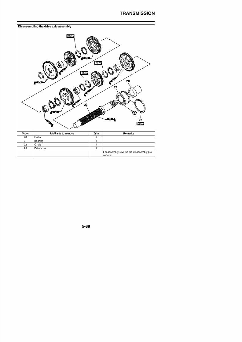
8/21/2019 Fz8 - Service Manual
http://slidepdf.com/reader/full/fz8-service-manual 353/609
For assembly, reverse the disassembly pro-
cedure.
TRANSMISSION
EAS26250
REMOVING THE TRANSMISSION1. Remove:
• Drive axle assembly “1”• Shift drum retainers “2”• Shift fork guide bars• Shift fork “L” and “R”• Shift drum assembly
• Shift fork “C”
2. Remove:• Bearing housing “1”• Main axle assembly “2”
a. Insert two bolts “3” of the proper size, asshown in the illustration, into the main axleassembly bearing housing.
EAS26260
CHECKING THE SHIFT FORKSThe following procedure applies to all of the
shift forks.1. Check:
• Shift fork cam follower “1”• Shift fork pawl “2”
Bends/damage/scoring/wear → Replacethe shift fork.
2. Check:• Shift fork guide bar
Roll the shift fork guide bar on a flat sur-
face.Bends → Replace.
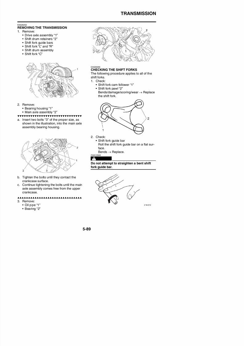
8/21/2019 Fz8 - Service Manual
http://slidepdf.com/reader/full/fz8-service-manual 354/609
Bends → Replace.
WARNING
EWA12840
Do not attempt to straighten a bent shiftfork guide bar.
TRANSMISSION
3. Check:• Shift fork movement(along the shift fork guide bar)Rough movement → Replace the shiftforks and shift fork guide bar as a set.
EAS26270
CHECKING THE SHIFT DRUM ASSEMBLY
1. Check:• Shift drum groove
Damage/scratches/wear → Replace theshift drum assembly.
• Shift drum segment “1”Damage/wear → Replace the shift drumassembly.
• Shift drum bearing “2”
Damage/pitting → Replace the shift drumassembly.
2. Measure:• Drive axle runout
(with a centering device and dial gauge“1”)Out of specification → Replace the drive
axle.
3. Check:
• Transmission gearsBlue discoloration/pitting/wear →
Drive axle runout limit0.08 mm (0.0032 in)
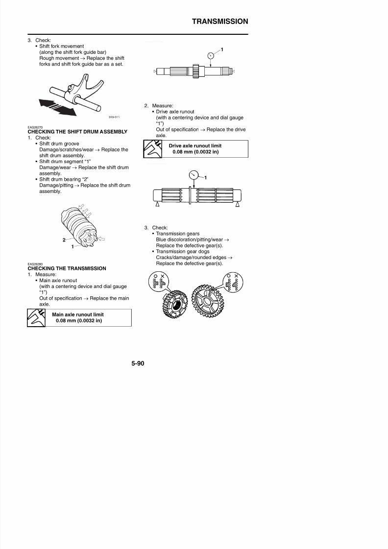
8/21/2019 Fz8 - Service Manual
http://slidepdf.com/reader/full/fz8-service-manual 355/609
EAS26280
CHECKING THE TRANSMISSION
Replace the defective gear(s).• Transmission gear dogs
Cracks/damage/rounded edges → Replace the defective gear(s).
TRANSMISSION
4. Check:• Transmission gear engagement(each pinion gear to its respective wheelgear)Incorrect → Reassemble the transmis-sion axle assemblies.
5. Check:• Transmission gear movement
Rough movement→
Replace the defec-tive part(s).6. Check:
• CirclipsBends/damage/looseness → Replace.
EAS29020
ASSEMBLING THE MAIN AXLE AND DRIVEAXLE
1. Install:• Toothed washer “1”
• Circlip “2”
TIP
• Be sure the circlip sharp-edged corner “a” ispositioned opposite side to the toothedwasher and gear.
• Align the opening between the ends “b” ofthe circlip with a groove “c” in the axle.
“c” on the retainer with an axle spline “b”, andthen install the toothed lock washer “2”.• Be sure to align the projection on the toothed
lock washer that is between the alignmentmarks “e” with the alignment mark “d” on theretainer.
EAS26350
INSTALLING THE TRANSMISSION1. Install:
• Bearing “1”
TIP
Make the seal side of bearing face to the out-side and install it close to the right end face of
the crankcase.
• Oil pipe “2”
New
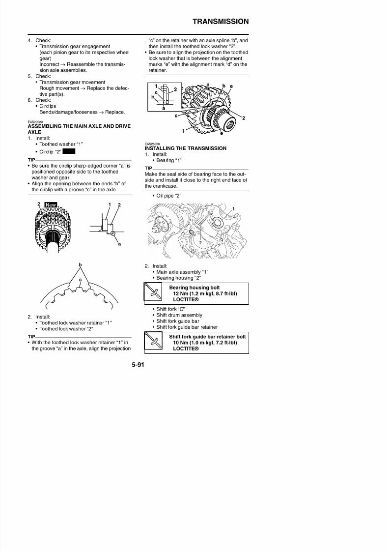
8/21/2019 Fz8 - Service Manual
http://slidepdf.com/reader/full/fz8-service-manual 356/609
2. Install:• Main axle assembly “1”
TRANSMISSION
TIP• The embossed marks on the shift forks
should face towards the right side of theengine and be in the following sequence: “R”,“C”, “L”.
• Carefully position the shift forks so that theyare installed correctly into the transmissiongears.
• Install shift fork “C” into the groove in the 3rdand 4th pinion gear on the main axle.
3. Install:• Shift fork “L” “1” and “R” “2”• Drive axle assembly “3”• Shift fork guide bar• Shift fork guide bar retainer “4”
TIP
• Install shift fork “L” into the groove in the 6thwheel gear and shift fork “R” into the groovei th 5th h l th d i l
4. Check:• Transmission
Rough movement → Repair.
TIP
Oil each gear, shaft, and bearing thoroughly.
Shift fork guide bar retainer bolt10 Nm (1.0 m·kgf, 7.2 ft·lbf)LOCTITE®
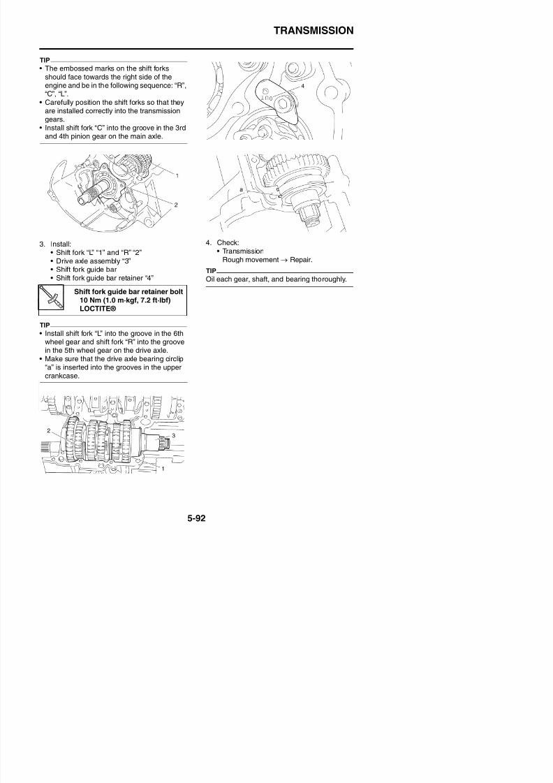
8/21/2019 Fz8 - Service Manual
http://slidepdf.com/reader/full/fz8-service-manual 357/609
in the 5th wheel gear on the drive axle.• Make sure that the drive axle bearing circlip
“a” is inserted into the grooves in the uppercrankcase.
TRANSMISSION

8/21/2019 Fz8 - Service Manual
http://slidepdf.com/reader/full/fz8-service-manual 358/609
6
COOLING SYSTEM
RADIATOR ....................................................................................................6-1CHECKING THE RADIATOR..................................................................6-3INSTALLING THE RADIATOR................................................................ 6-3
OIL COOLER ................................................................................................6-5
CHECKING THE OIL COOLER..............................................................6-6INSTALLING THE OIL COOLER............................................................6-6
THERMOSTAT ..............................................................................................6-7CHECKING THE THERMOSTAT............................................................6-9ASSEMBLING THE THERMOSTAT ASSEMBLY ................................... 6-9INSTALLING THE THERMOSTAT ASSEMBLY .................................... 6-10
WATER PUMP ............................................................................................6-11DISASSEMBLING THE WATER PUMP................................................6-12CHECKING THE WATER PUMP..........................................................6-12ASSEMBLING THE WATER PUMP......................................................6-12
8/21/2019 Fz8 - Service Manual
http://slidepdf.com/reader/full/fz8-service-manual 359/609
6
RADIATOR
EAS26380
RADIATORRemoving the radiator
Order Job/Parts to remove Q’ty Remarks
Rider seat Refer to “GENERAL CHASSIS” on page 4 1
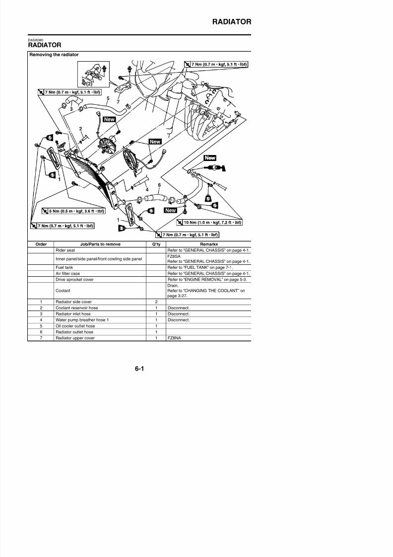
8/21/2019 Fz8 - Service Manual
http://slidepdf.com/reader/full/fz8-service-manual 360/609
Rider seat Refer to GENERAL CHASSIS on page 4-1.
Inner panel/side panel/front cowling side panelFZ8SARefer to “GENERAL CHASSIS” on page 4-1.
Fuel tank Refer to “FUEL TANK” on page 7-1.
Air filter case Refer to “GENERAL CHASSIS” on page 4-1.
RADIATOR
Removing the radiator
Order Job/Parts to remove Q’ty Remarks
8 Radiator upper panel 1 FZ8SA
9 Radiator fan motor coupler 2 Disconnect.
10 Radiator 1
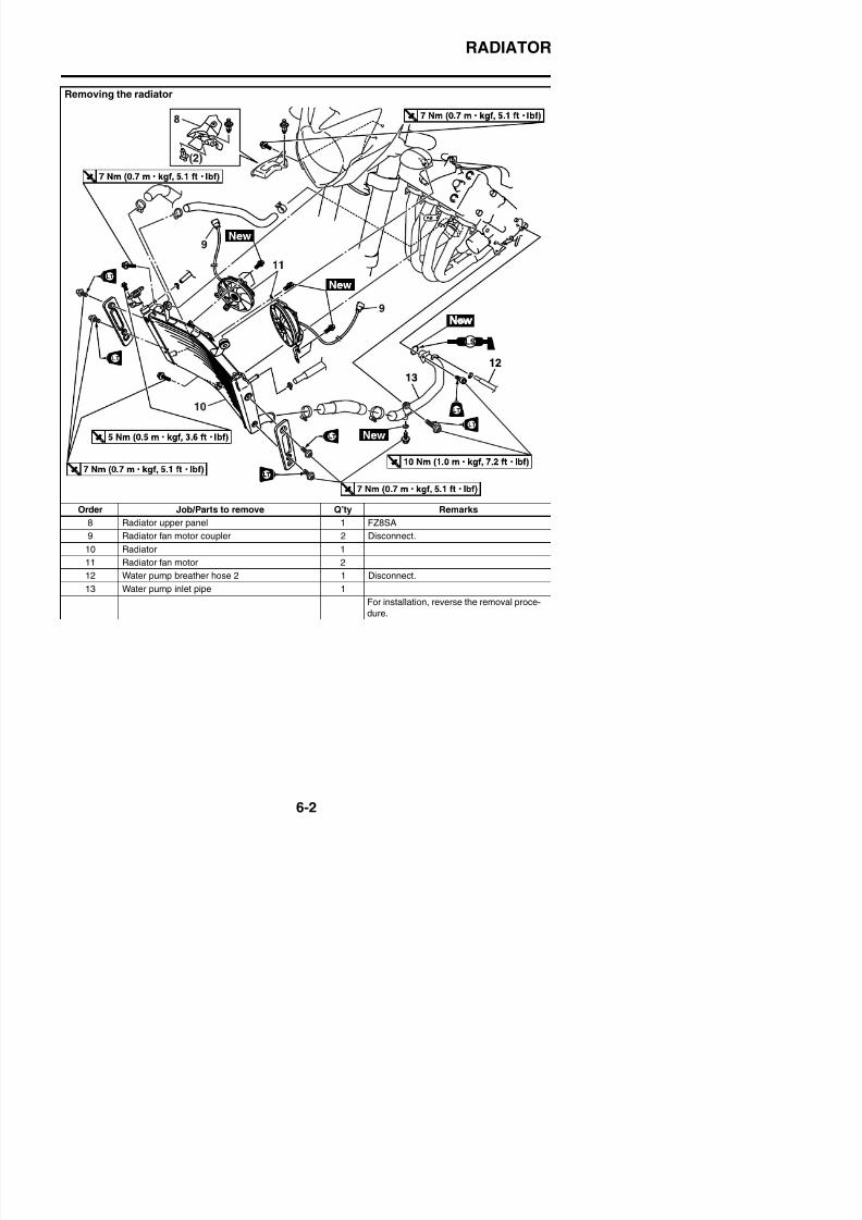
8/21/2019 Fz8 - Service Manual
http://slidepdf.com/reader/full/fz8-service-manual 361/609
10 Radiator 1
11 Radiator fan motor 2
12 Water pump breather hose 2 1 Disconnect.
13 Water pump inlet pipe 1
For installation, reverse the removal proce-
RADIATOR
EAS26390
CHECKING THE RADIATOR1. Check:
• Radiator finsObstruction → Clean.Apply compressed air to the rear of theradiator.Damage → Repair or replace.
TIP
Straighten any flattened fins with a thin, flat-head screwdriver.
2. Check:• Radiator hoses• Radiator pipes
Cracks/damage → Replace.3. Measure:
• Radiator cap opening pressureBelow the specified pressure → Replacethe radiator cap.
a. Install the radiator cap tester “1” and radia-
b. Apply the specified pressure for ten sec-onds and make sure there is no drop in
pressure.
4. Check:
• Radiator fanDamage → Replace.Malfunction → Check and repair.Refer to “COOLING SYSTEM” on page8-41.
EAS26400
INSTALLING THE RADIATOR1. Fill:
• Cooling system(with the specified amount of the recom-mended coolant)Refer to “CHANGING THE COOLANT”on page 3-27.
2. Check:
• Cooling systemLeaks → Repair or replace any faulty
part.
a. Attach the radiator cap tester “1” and radia-
Radiator cap opening pressure93.3–122.7 kPa (0.93–1.23 kgf/ cm², 13.5–17.8 psi)
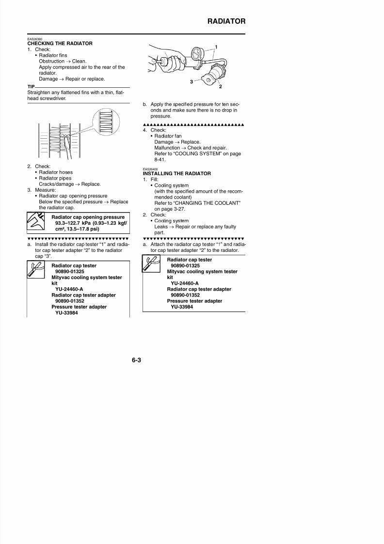
8/21/2019 Fz8 - Service Manual
http://slidepdf.com/reader/full/fz8-service-manual 362/609
a. Install the radiator cap tester 1 and radia
tor cap tester adapter “2” to the radiatorcap “3”.
a. Attach the radiator cap tester 1 and radiator cap tester adapter “2” to the radiator.
Radiator cap tester0 0 0
Radiator cap tester90890-01325
Mi li
RADIATOR
b. Apply 122.7 kPa (1.23 kgf/cm², 17.8 psi) ofpressure.
c. Measure the indicated pressure with the
gauge.
3. Measure:• Radiator cap opening pressureBelow the specified pressure → Replacethe radiator cap.Refer to “CHECKING THE RADIATOR”on page 6-3.
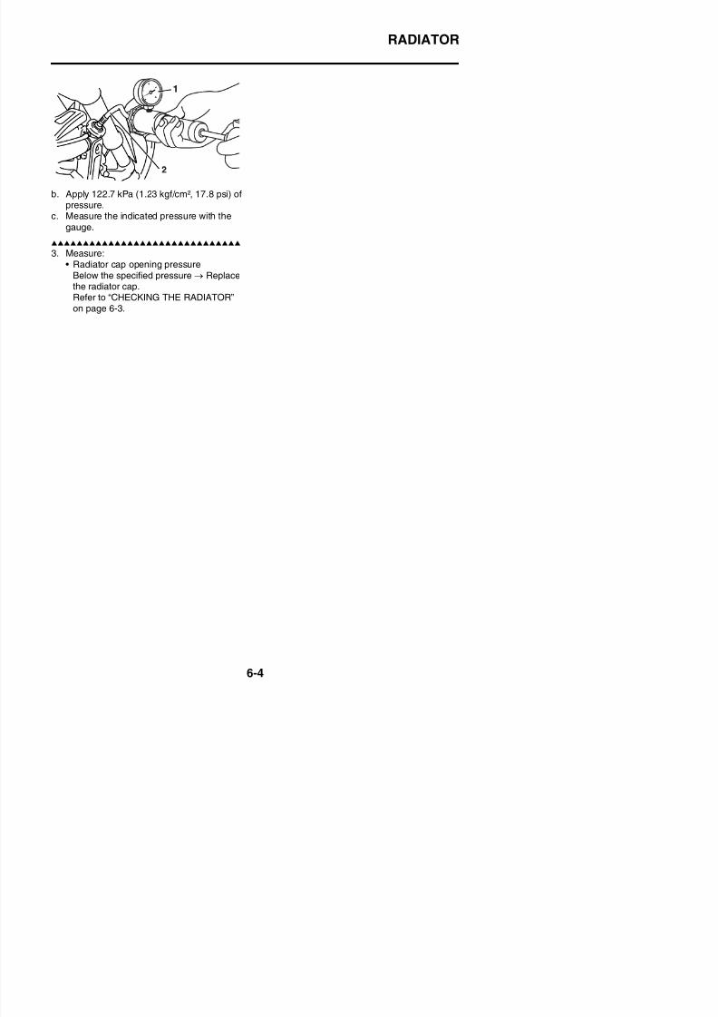
8/21/2019 Fz8 - Service Manual
http://slidepdf.com/reader/full/fz8-service-manual 363/609
OIL COOLER
EAS26410
OIL COOLERRemoving the oil cooler
Order Job/Parts to remove Q’ty Remarks
Coolant
Drain.
Refer to “CHANGING THE COOLANT” on
page 3-27
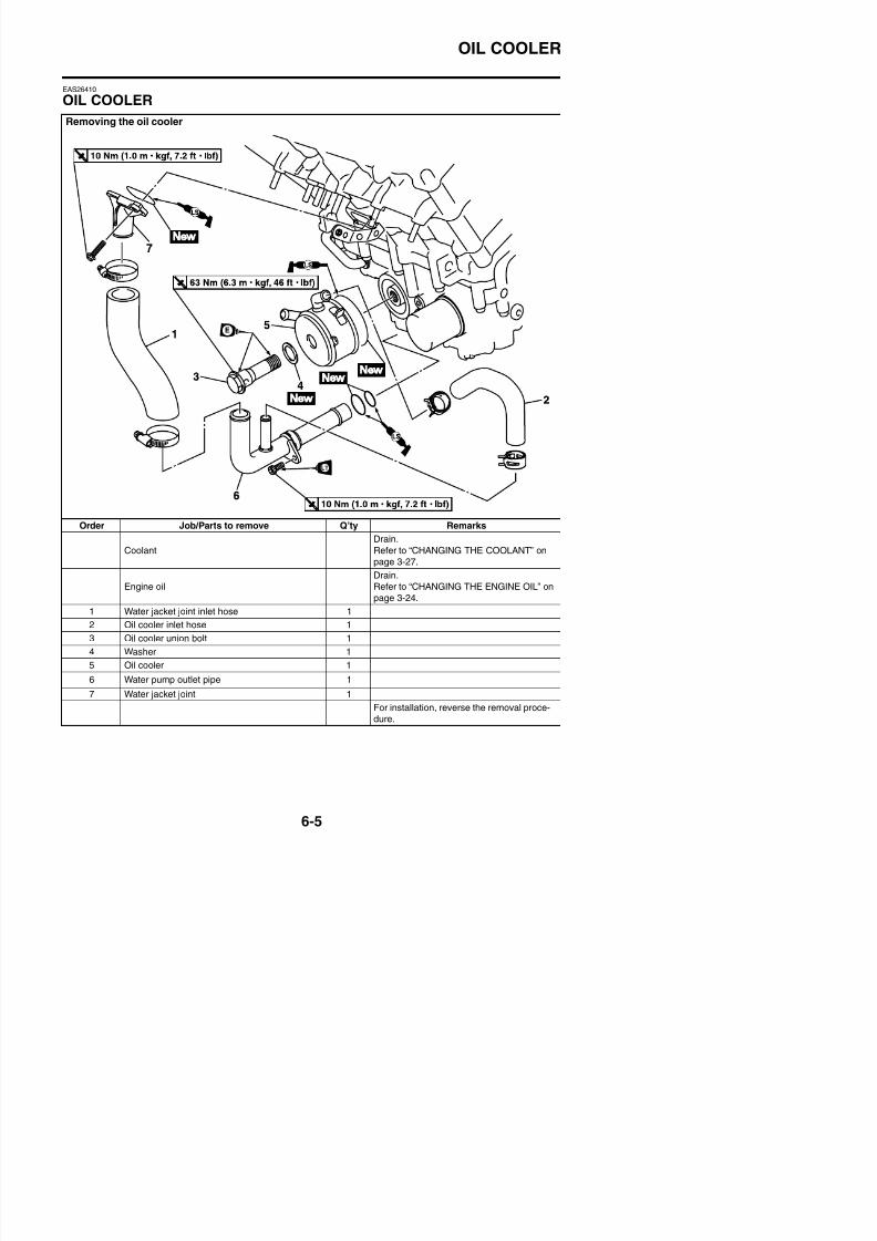
8/21/2019 Fz8 - Service Manual
http://slidepdf.com/reader/full/fz8-service-manual 364/609
page 3 27.
Engine oil
Drain.
Refer to “CHANGING THE ENGINE OIL” on
page 3-24.
1 Water jacket joint inlet hose 1
OIL COOLER
EAS26420
CHECKING THE OIL COOLER1. Check:
• Oil coolerCracks/damage → Replace.
2. Check:• Oil cooler inlet hose• Oil cooler outlet hose
Cracks/damage/wear → Replace.
EAS26430
INSTALLING THE OIL COOLER1. Clean:
• Mating surfaces of the oil cooler and thecrankcase(with a cloth dampened with lacquer thin-ner)
2. Install:
• O-ring
• Oil cooler “1”
• Washer “2”
• Oil cooler union bolt “3”
TIP
• Before installing the oil cooler, apply engineoil lightly to the oil cooler union bolt andapply lithium-soap-based grease to the O-ring.
• Make sure the O-ring is positioned properly.• Align the projection “a” on the oil cooler with
the slot “b” in the crankcase.
• Crankcase(with the specified amount of the recom-mended engine oil)Refer to “CHANGING THE ENGINE OIL”on page 3-24.
4. Check:• Cooling system
Leaks → Repair or replace any faultypart.Refer to “INSTALLING THE RADIATOR”on page 6-3.
5. Measure:• Radiator cap opening pressure
Below the specified pressure → Replacethe radiator cap.Refer to “CHECKING THE RADIATOR”on page 6-3.
Oil cooler union bolt63 Nm (6.3 m·kgf, 46 ft·lbf)
New
New

8/21/2019 Fz8 - Service Manual
http://slidepdf.com/reader/full/fz8-service-manual 365/609
THERMOSTAT
EAS26440
THERMOSTATRemoving the thermostat assembly
Order Job/Parts to remove Q’ty Remarks
Rider seat Refer to “GENERAL CHASSIS” on page 4-1.
Inner panel/side panel/front cowling side panelFZ8SA
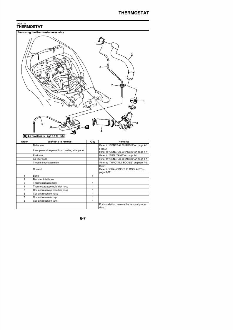
8/21/2019 Fz8 - Service Manual
http://slidepdf.com/reader/full/fz8-service-manual 366/609
Inner panel/side panel/front cowling side panelRefer to “GENERAL CHASSIS” on page 4-1.
Fuel tank Refer to “FUEL TANK” on page 7-1.
Air filter case Refer to “GENERAL CHASSIS” on page 4-1.
Throttle body assembly Refer to “THROTTLE BODIES” on page 7-5.
THERMOSTAT
Disassembling the thermostat assembly
Order Job/Parts to remove Q’ty Remarks
1 Thermostat housing cover 1
2 Thermostat 1
3 Thermostat housing 1
For assembly, reverse the disassembly pro-
cedure.
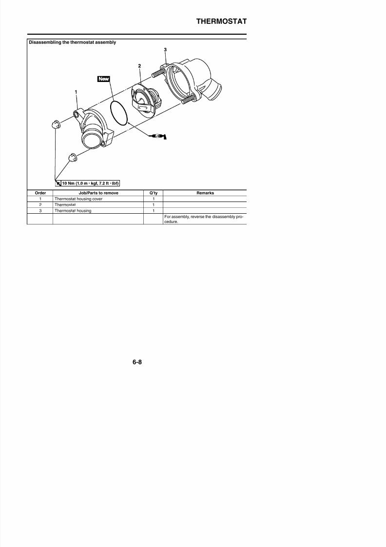
8/21/2019 Fz8 - Service Manual
http://slidepdf.com/reader/full/fz8-service-manual 367/609
THERMOSTAT
EAS26450
CHECKING THE THERMOSTAT1. Check:
• ThermostatDoes not open at 71–85 °C (159.8–185.0°F) → Replace.
a. Suspend the thermostat “1” in a container“2” filled with water.
b. Slowly heat the water “3”.c. Place a thermometer “4” in the water.d. While stirring the water, observe the ther-
mostat and thermometer’s indicated tem-
perature.
TIPIf the accuracy of the thermostat is in doubt,replace it. A faulty thermostat could cause seri-ous overheating or overcooling.
2. Check:• Thermostat housing cover “1”
• Thermostat housing “2”Cracks/damage → Replace.
EAS26460
ASSEMBLING THE THERMOSTAT ASSEM-BLY1. Install:
• Thermostat housing “1”• Thermostat “2”
• O-ring “3”
• Thermostat housing cover “4”
TIPInstall the thermostat with its breather hole “a”
facing up.
Thermostat housing cover nut10 Nm (1.0 m·kgf, 7.2 ft·lbf)
New
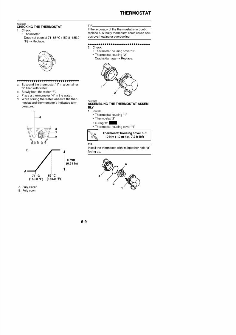
8/21/2019 Fz8 - Service Manual
http://slidepdf.com/reader/full/fz8-service-manual 368/609
THERMOSTAT
EAS26480
INSTALLING THE THERMOSTAT ASSEM-BLY1. Fill:
• Cooling system(with the specified amount of the recom-mended coolant)Refer to “CHANGING THE COOLANT”
on page 3-27.
2. Check:• Cooling system
Leaks → Repair or replace any faultypart.Refer to “INSTALLING THE RADIATOR”on page 6-3.
3. Measure:• Radiator cap opening pressure
Below the specified pressure → Replacethe radiator cap.Refer to “CHECKING THE RADIATOR”on page 6-3.
8/21/2019 Fz8 - Service Manual
http://slidepdf.com/reader/full/fz8-service-manual 369/609
WATER PUMP
EAS26500
WATER PUMPDisassembling the water pump
Order Job/Parts to remove Q’ty Remarks
Oil/water pump assembly Refer to “OIL PUMP” on page 5-57.
Oil pump rotor Refer to “OIL PUMP” on page 5-57.
1 Water pump cover 1
2 Pin 2
3 I ll h f ( l i h h i ll ) 1
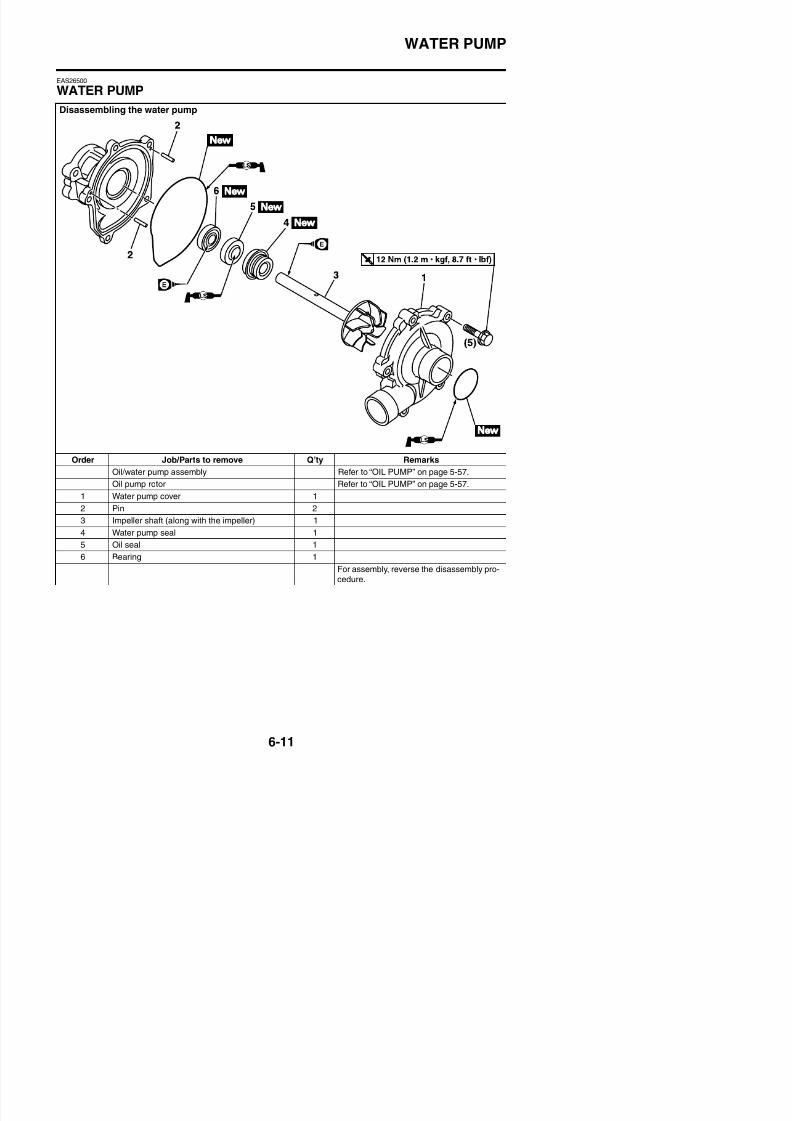
8/21/2019 Fz8 - Service Manual
http://slidepdf.com/reader/full/fz8-service-manual 370/609
3 Impeller shaft (along with the impeller) 1
4 Water pump seal 1
5 Oil seal 1
6 Bearing 1
WATER PUMP
EAS26520
DISASSEMBLING THE WATER PUMP1. Remove:
• Water pump seal “1”
TIP
Remove the water pump seal from the insideof the water pump housing “2”.
2. Remove:• Oil seal “1”• Bearing “2”
TIP
Remove the oil seal and bearing from the out-side of the water pump housing “3”.
3. Remove:• Rubber damper holder “1”
EAS26541
CHECKING THE WATER PUMP1. Check:
• Water pump housing cover “1”• Impeller “2”
Cracks/damage/wear → Replace.• Water pump housing “3”
Cracks/damage/wear → Replace the oil/
water pump assembly.
2. Check:• Bearing
Rough movement → Replace.3. Check:
• Water pump outlet pipe• Water pump inlet pipe
Cracks/damage/wear → Replace.
EAS26560
ASSEMBLING THE WATER PUMP1. Install:
• Bearing “1”
• Oil seal “2”
(into the water pump housing “3”)
TIP
Installed depth “a”17.2 mm (0.68 in)
New
New
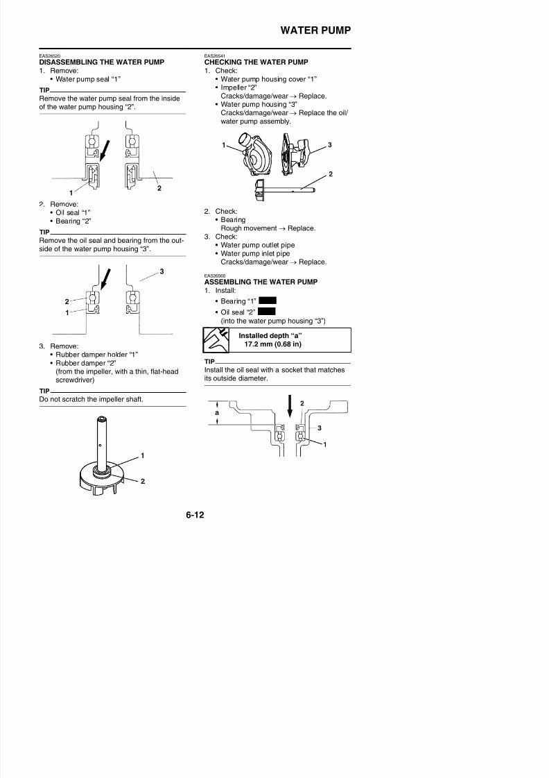
8/21/2019 Fz8 - Service Manual
http://slidepdf.com/reader/full/fz8-service-manual 371/609
• Rubber damper “2”(from the impeller, with a thin, flat-headscrewdriver)
TIP
Install the oil seal with a socket that matchesits outside diameter.
WATER PUMP
2. Install:
• Water pump seal “1”ECA14080
Never lubricate the water pump seal sur-face with oil or grease.
TIP
Install the water pump seal with the special
tools.
4. Measure:• Impeller shaft tilt
Out of specification → Repeat steps (3)and (4).
ECA14090
Make sure the rubber damper and rubberdamper holder are flush with the impeller.
Mechanical seal installer90890-04078
Water pump seal installerYM-33221-A
Middle driven shaft bearingdriver
90890-04058Middle drive bearing installer 40& 50 mm
YM-04058
2. Water pump housing
3. Mechanical seal installer
4. Middle driven shaft bearing driver
New
Impeller shaft tilt limit0.15 mm (0.006 in)
1. Straightedge
2. Impeller
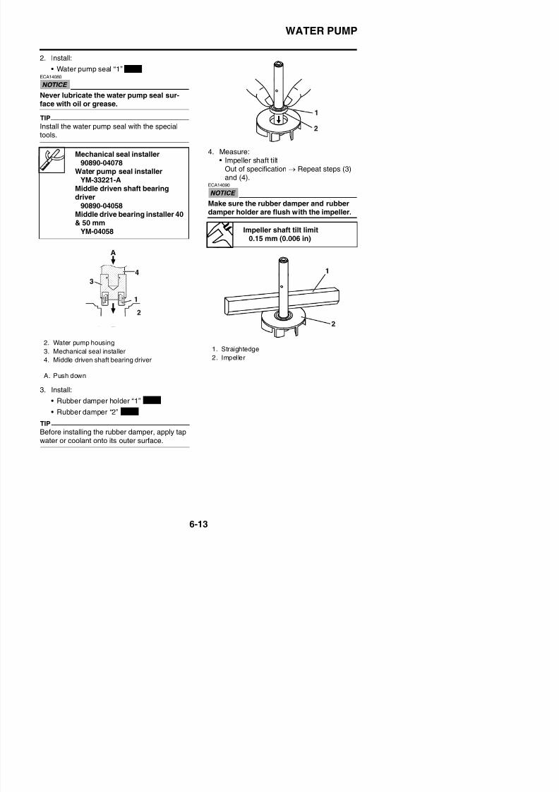
8/21/2019 Fz8 - Service Manual
http://slidepdf.com/reader/full/fz8-service-manual 372/609
3. Install:
A. Push down
FUEL SYSTEM
FUEL TANK ..................................................................................................7-1REMOVING THE FUEL TANK COVER ..................................................7-2REMOVING THE FUEL TANK................................................................7-2REMOVING THE FUEL PUMP...............................................................7-2CHECKING THE FUEL PUMP BODY ....................................................7-2CHECKING THE FUEL PUMP OPERATION .........................................7-3
INSTALLING THE FUEL PUMP..............................................................7-3INSTALLING THE FUEL TANK...............................................................7-3INSTALLING THE FUEL TANK COVER .................................................7-3CHECKING THE FUEL PRESSURE......................................................7-4
THROTTLE BODIES.....................................................................................7-5REMOVING THE FUEL HOSE (THROTTLE BODY SIDE) ....................7-8
CHECKING THE FUEL INJECTORS .....................................................7-8INSTALLING THE INJECTORS..............................................................7-8CHECKING THE INJECTOR PRESSURE.............................................7-8CHECKING AND CLEANING THE THROTTLE BODIES ...................... 7-9INSTALLING THE FUEL HOSE (THROTTLE BODY SIDE) .................7-11ADJUSTING THE THROTTLE POSITION SENSOR ........................... 7-11ADJUSTING THE SUB-THROTTLE POSITION SENSOR...................7-12
AIR INDUCTION SYSTEM .........................................................................7-15CHECKING THE AIR INDUCTION SYSTEM....................................... 7-18INSTALLING THE AIR INDUCTION SYSTEM .....................................7-18
8/21/2019 Fz8 - Service Manual
http://slidepdf.com/reader/full/fz8-service-manual 373/609
7
FUEL TANK
EAS26620
FUEL TANKRemoving the fuel tank
Order Job/Parts to remove Q’ty Remarks
Rider seat Refer to “GENERAL CHASSIS” on page 4-1.
Inner panel/side panel/front cowling side panelFZ8SA
Refer to “GENERAL CHASSIS” on page 4-1
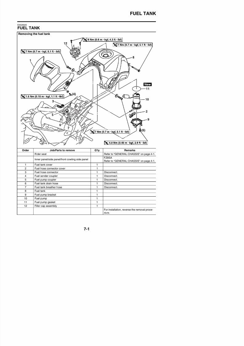
8/21/2019 Fz8 - Service Manual
http://slidepdf.com/reader/full/fz8-service-manual 374/609
Refer to GENERAL CHASSIS on page 4 1.
1 Fuel tank cover 1
2 Fuel hose connector cover 1
3 F l h t 1 Di t
FUEL TANK
EAS39P1713
REMOVING THE FUEL TANK COVER1. Remove:
• Fuel tank cover “1”
a. Remove the bolts.b. Disengage the projections from both ends
of the fuel tank, slightly expanding both
ends of the fuel tank cover.
c. Slide the right side of the fuel tank coverslightly forward to disengage projections“a” from the fuel tank cover bracket. Addi-tionally, lift the rear of the cover (like turningover the cover) to disengage projection “b”
from the cover bracket.
WARNING
EWA39P1702
Cover fuel hose connection with a clothwhen disconnecting them. Residual pres-sure in the fuel lines could cause fuel tospurt out when removing the hose.
ECA14B1003
Be sure to disconnect the fuel hose byhand. Do not forcefully disconnect the hosewith tools.
TIP
• To remove the fuel hose from the fuel pump,press the two buttons “1” on the sides of theconnector, and then remove the hose.
• Before removing the hose, place a few rags
in the area under where it will be removed.• It is prohibited to wear the cotton work gloves
or equivalent coverings.
4. Remove:• Fuel tank
TIP
Do not set the fuel tank down so that the instal-lation surface of the fuel pump is directly underthe tank. Be sure to lean the fuel tank in an
upright position.
EAS26640
REMOVING THE FUEL PUMP
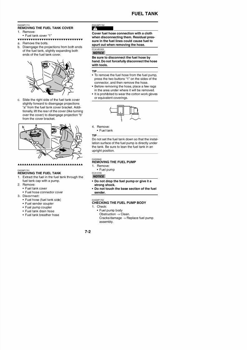
8/21/2019 Fz8 - Service Manual
http://slidepdf.com/reader/full/fz8-service-manual 375/609
EAS39P1701
REMOVING THE FUEL TANK
1. Remove:• Fuel pump
ECA14720
FUEL TANK
EAS26690
CHECKING THE FUEL PUMP OPERATION1. Check:
• Fuel pump operationRefer to “CHECKING THE FUEL PRES-SURE” on page 7-4.
EAS39P1703
INSTALLING THE FUEL PUMP1. Install:
• Fuel pump gasket
• Fuel pump• Fuel pump bracket• Fuel pump bolts
TIP
• Do not damage the installation surfaces ofthe fuel tank when installing the fuel pump.
• Always use a new fuel pump gasket.• Install the fuel pump gasket so that the lip
side turns to the inside of the fuel tank.• Install the fuel pump as shown in the illustra-
tion.
• Align the projection “a” on the fuel pump withthe slot in the fuel pump bracket.
• Tighten the fuel pump bolts in the propertightening sequence as shown.
is in the correct position, otherwise the fuel
hose will not be properly installed.
TIP
• Install the fuel hose securely onto the fuelpump until a distinct “click” is heard.
• It is prohibited to wear the cotton work glovesor equivalent coverings.
• Attach the fuel hose connector cover “1” to
the fuel hose connector “2” from the bottom.Make sure that parts “a” are firmly attachedto the fuel hose connector.
2. Connect:• Fuel tank breather hose
• Fuel tank drain hose• Fuel pump coupler• Fuel sender coupler
EAS39P1714
INSTALLING THE FUEL TANK COVER1. Install:
• Fuel tank cover
a. Insert projections “a” under the fuel tankcover bracket while insert projection “b” intothe hole of the fuel tank cover bracket.
Fuel pump bolt
4.0 Nm (0.40 m·kgf, 2.9 ft·lbf)
New
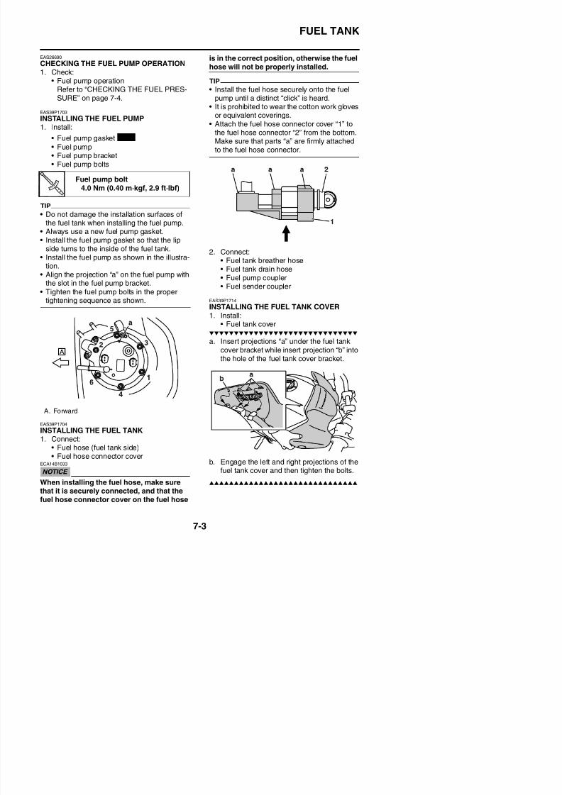
8/21/2019 Fz8 - Service Manual
http://slidepdf.com/reader/full/fz8-service-manual 376/609
FUEL TANK
EAS39P1709
CHECKING THE FUEL PRESSURE1. Check:
• Fuel pressure
a. Remove the rider seat and fuel tank cover.Refer to “GENERAL CHASSIS” on page 4-1 and “FUEL TANK” on page 7-1.
b. Remove the fuel tank bolt and holdup the
fuel tank.c. Disconnect the fuel hose “1” from the fuel
pump.Refer to “REMOVING THE FUEL TANK” onpage 7-2.
WARNING
EWA39P1702
Cover fuel hose connection with a cloth
when disconnecting them. Residual pres-sure in the fuel lines could cause fuel tospurt out when removing the hose.
ECA14B1003
Be sure to disconnect the fuel hose byhand. Do not forcefully disconnect the hosewith tools.
d. Connect the pressure gauge “2” and fuel
e. Start the engine.f. Measure the fuel pressure.
Faulty → Replace the fuel pump.
Fuel pressure324.0 kPa (3.24 kgf/cm², 47.0
psi)
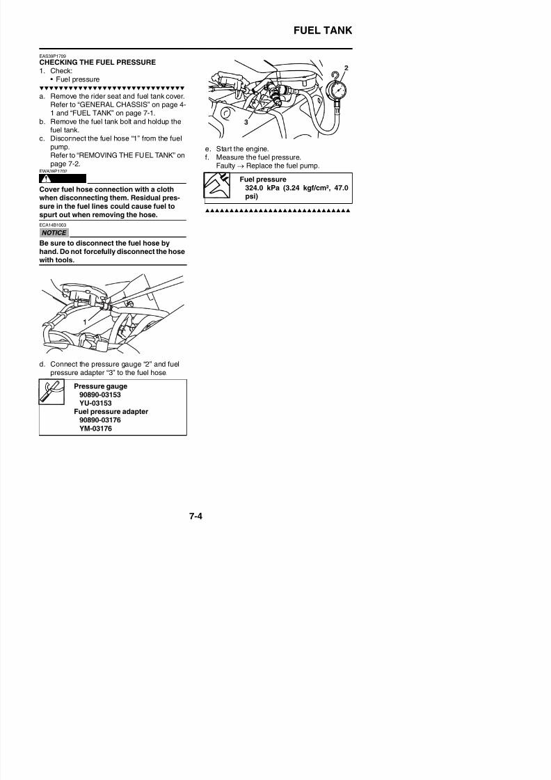
8/21/2019 Fz8 - Service Manual
http://slidepdf.com/reader/full/fz8-service-manual 377/609
p g gpressure adapter “3” to the fuel hose.
Pressure gauge
THROTTLE BODIES
EAS26970
THROTTLE BODIESRemoving the throttle bodies
Order Job/Parts to remove Q’ty Remarks
Rider seat Refer to “GENERAL CHASSIS” on page 4-1.
Inner panel/side panel/front cowling side panelFZ8SA
Refer to “GENERAL CHASSIS” on page 4-1.
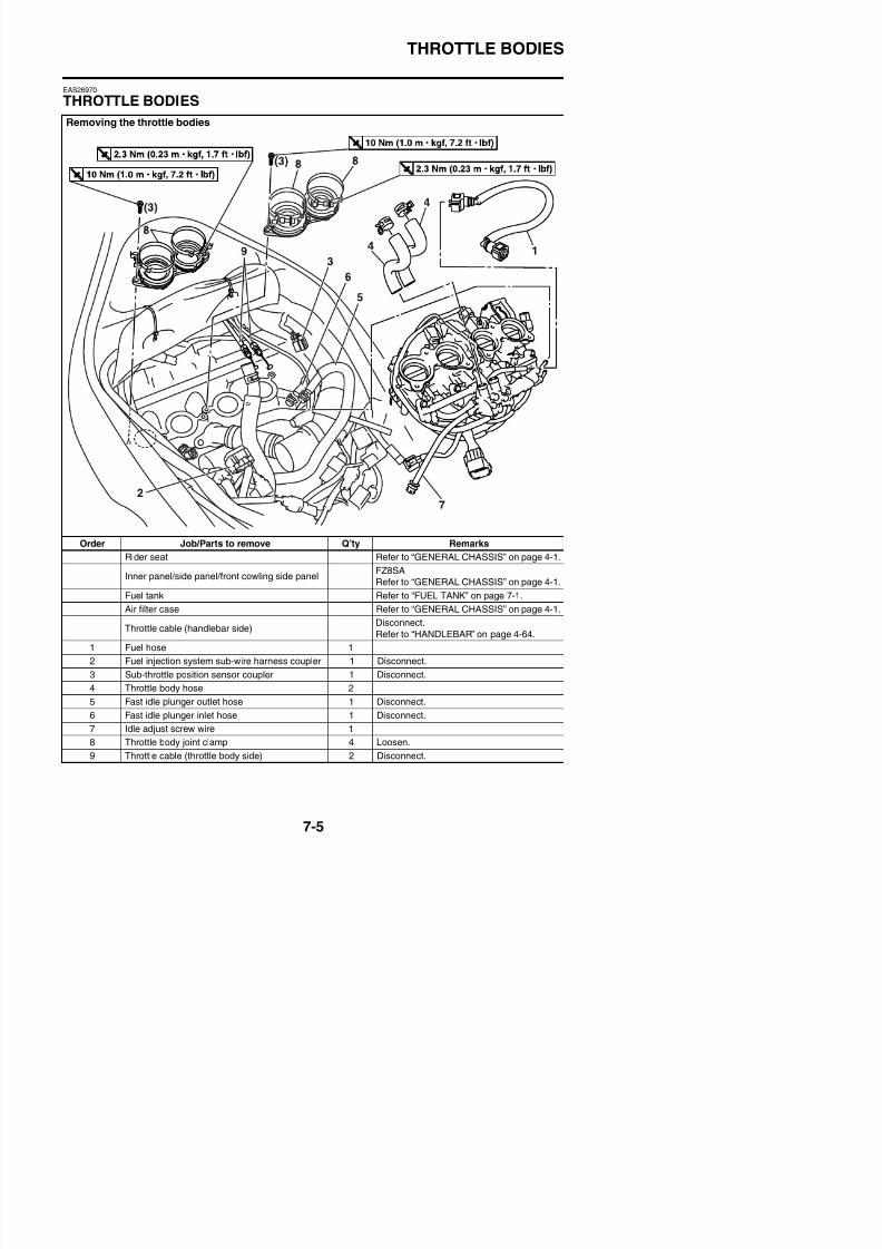
8/21/2019 Fz8 - Service Manual
http://slidepdf.com/reader/full/fz8-service-manual 378/609
Fuel tank Refer to “FUEL TANK” on page 7-1.
Air filter case Refer to “GENERAL CHASSIS” on page 4-1.
THROTTLE BODIES
Removing the throttle bodies
Order Job/Parts to remove Q’ty Remarks
10 Coolant temperature sensor coupler 1 Disconnect.
11 Throttle bodies 1
12 Throttle body joint 2
For installation, reverse the removal proce-
dure.
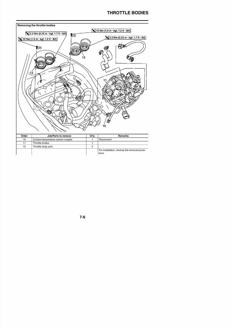
8/21/2019 Fz8 - Service Manual
http://slidepdf.com/reader/full/fz8-service-manual 379/609
THROTTLE BODIES
Removing the injectors
Order Job/Parts to remove Q’ty Remarks
1 Fuel injection system sub-wire harness 1
2 Hose joint 5
3 Negative pressure hose (Thin) 11
4 Negative pressure hose (Thick) 4
5 Intake air pressure sensor 1
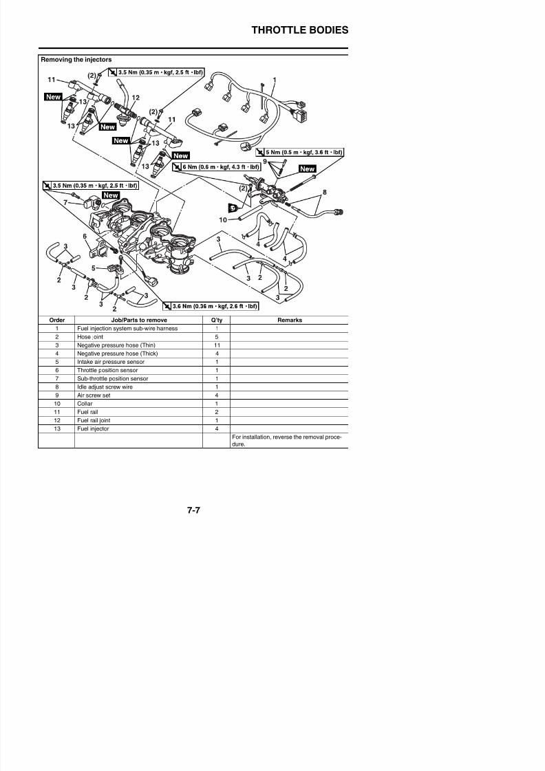
8/21/2019 Fz8 - Service Manual
http://slidepdf.com/reader/full/fz8-service-manual 380/609
6 Throttle position sensor 1
7 Sub-throttle position sensor 1
THROTTLE BODIES
EAS39P1710
REMOVING THE FUEL HOSE (THROTTLEBODY SIDE)1. Remove:
• Fuel tankRefer to “REMOVING THE FUEL TANK”on page 7-2.
2. Remove:
• Fuel hose (throttle body side)ECA14B1003
Be sure to disconnect the fuel hose byhand. Do not forcefully disconnect the hosewith tools.
TIP
• To remove the fuel hose from the fuel rail joint, slide the fuel hose connector cover “1”
on the end of the hose in the direction of thearrow shown, press the two buttons “2” onthe sides of the connector, and then removethe hose.
• Before removing the hose, place a few ragsin the area under where it will be removed.
• It is prohibited to wear the cotton work glovesor equivalent coverings.
EAS26980
CHECKING THE FUEL INJECTORS
WARNING
EWA39P1703
battery terminal before checking the
injectors.ECA39P1701
• When checking the injectors, do not allowany foreign material to enter or adhere tothe injectors, fuel rail, or O-rings.
• If an injector is subject to strong shocksor excessive force, replace it.
1. Check:• Injectors
Damage/defective → Replace.Refer to “FUEL INJECTION SYSTEM” onpage 8-47.
EAS39P1705
INSTALLING THE INJECTORS
ECA39P1702
• Always use new O-rings.• When installing the injectors, do not allow
any foreign material to enter or adhere tothe injectors, fuel rails, or O-rings.
• Be careful not to twist or pinch the O-rings when installing the injectors.
• When installing the injector, install it atthe same position as the removed cylin-der.
• If an injector is subject to strong shocksor excessive force, replace it.
1. Install a new seal onto the end of eachinjector.
2. Install the injectors to the fuel rail, makingsure to install them in the correct direction.
3. Install a seal onto the end of each injector.4. Install the injector assemblies to the throttle
bodies.
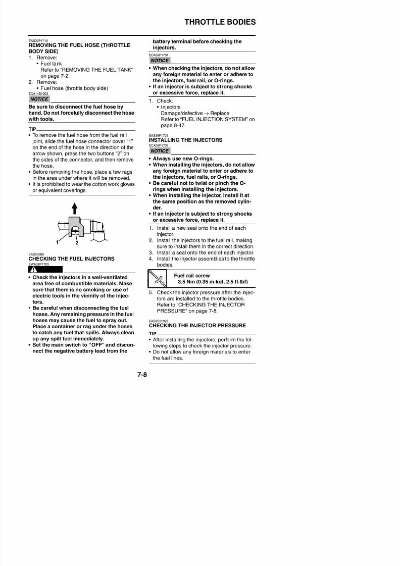
8/21/2019 Fz8 - Service Manual
http://slidepdf.com/reader/full/fz8-service-manual 381/609
WARNING
• Check the injectors in a well-ventilated Fuel rail screw3 5 N (0 35 k f 2 5 ft lbf)
THROTTLE BODIES
1. Check:
• Injector pressure
a. Connect the injector pressure adapter “1”to the fuel rail joint “2”, and then connect anair compressor “3” to the adapter.
b. Connect the pressure gauge “4” to theinjector pressure adapter “1”.
c. Close the valve on the injector pressureadapter.
d. Apply air pressure with the air compressor.e. Open the valve on the injector pressure
adapter until the specified pressure isreached.
ECA2S31073
Never exceed the specified air pressure or
EAS39P1706
CHECKING AND CLEANING THE THROT-TLE BODIES
TIP
Before cleaning the throttle bodies, check thefollowing items:• Valve clearance
• Spark plugs• Compression pressure
• Air filter element• Throttle body joints• Fuel hose• Air induction system• Exhaust system• Breather hoses• Vacuum hoses• Throttle body hoses
• Fast idle plunger inlet hose• Fast idle plunger outlet hose
WARNING
EWA14B1021
• If the throttle bodies are subjected tostrong shocks or dropped during clean-ing, replace them as a set.
• Before removing the throttle bodies toclean them, check the operation of thethrottle bodies, refer to “FUEL INJECTIONSYSTEM” on page 8-47.
1. Check:• Throttle bodies
Cracks/damage → Replace the throttlebodies as a set.
TIPIf the protector “a” is scratched or damaged,replace the throttle bodies as a set.
Pressure gauge90890-03153YU-03153
Fuel injector pressure adapter90890-03210YU-03210
Specific air pressure
490 kPa (5.0 kgf/cm², 71.1 psi)
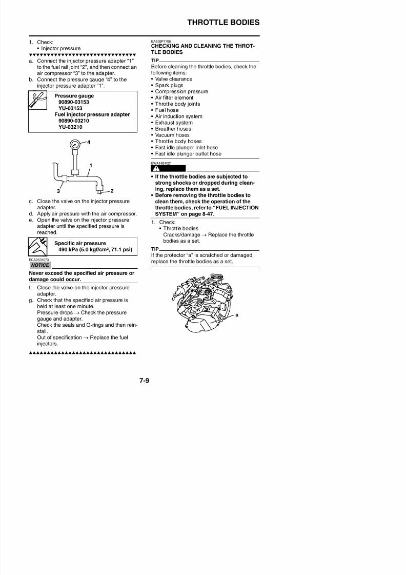
8/21/2019 Fz8 - Service Manual
http://slidepdf.com/reader/full/fz8-service-manual 382/609
Never exceed the specified air pressure ordamage could occur.
THROTTLE BODIES
2. Clean:
• Throttle bodiesECA39P1703
Observe the following precautions; other-wise, the throttle bodies may not operateproperly.• Do not open the throttle valves quickly.
• Do not subject the throttle bodies to
excessive force.• Clean the throttle bodies with a cloth
which petroleum-based solvent is appliedon.
• Do not use any caustic carburetor clean-ing solution.
• Do not apply cleaning solvent directly toany plastic parts, sensors, or seals.
• Do not directly push the throttle valves toopen them.
• Do not touch the synchronizing screws“a”, otherwise the throttle valve synchro-nization will be affected.
• Do not touch the throttle adjust screw“b”.
a. Place the throttle bodies on a flat surfacewith the engine side facing up
c. Push the lever in the direction shown in the
illustration to hold the throttle valves in theopen position.
WARNING
EWA14B1022
When cleaning the throttle bodies, be care-ful not to injure yourself on the throttlevalves or other components of the throttle
bodies.
ECA39P1704
Do not open the sub-throttle valves by sup-plying electrical power to the throttle bod-ies.
d. Apply a petroleum-based solvent to thethrottle valves and the inside of the throttlebodies to remove any carbon deposits.
TIP
• Do not allow any petroleum-based solvent toenter the opening for the injectors.
• Do not apply any petroleum-based solvent to
the portions of the throttle valve shaftsbetween the throttle bodies.
e. Remove the carbon deposits from theinside of each throttle body in a downwarddirection from the engine side of the throt
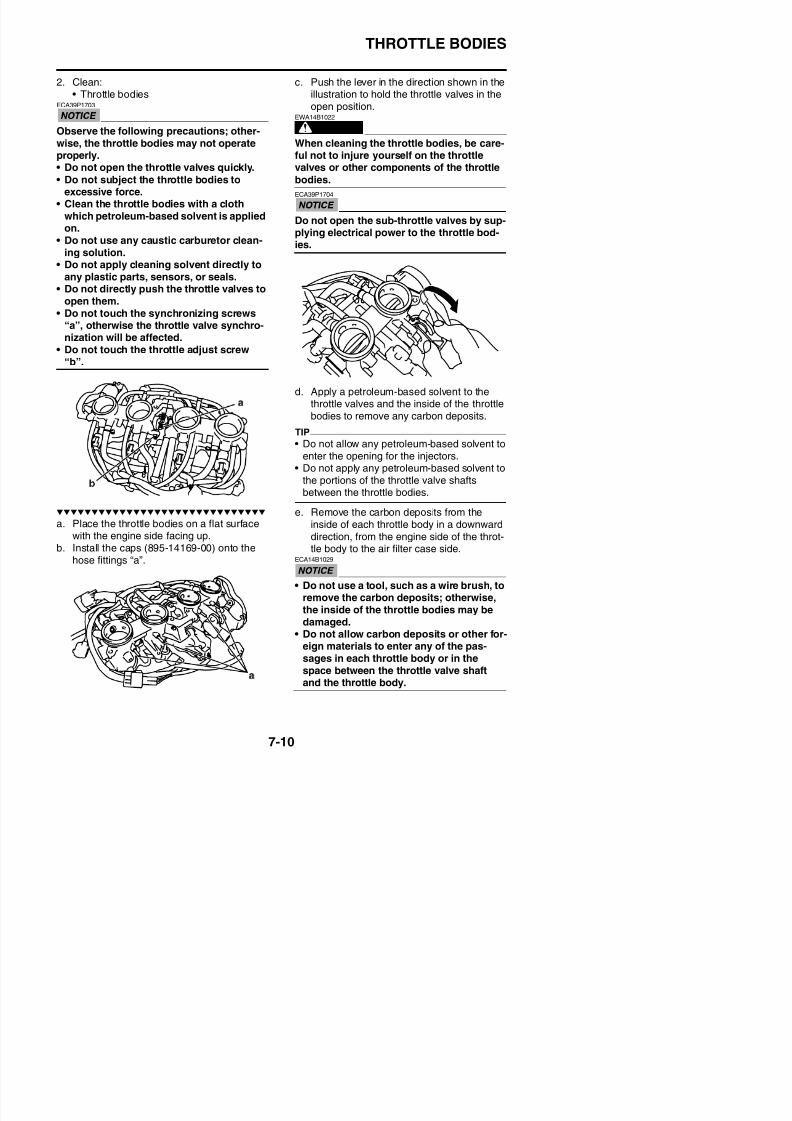
8/21/2019 Fz8 - Service Manual
http://slidepdf.com/reader/full/fz8-service-manual 383/609
with the engine side facing up.b. Install the caps (895-14169-00) onto the
direction, from the engine side of the throt-tle body to the air filter case side.
THROTTLE BODIES
f. After removing the carbon deposits, clean
the inside of the throttle bodies with apetroleum-based solvent, and then dry thethrottle bodies using compressed air.
g. Make sure that there are no carbon depos-its or other foreign materials in any of thepassages “a” in each throttle body, in thespace “b” between the throttle valve shaftand the throttle body or in the space “c”
between the sub throttle valve shaft and thethrottle body.
3. Check:• Fuel passages
Obstructions → Clean.
a Wash the throttle bodies in a petroleum-
EAS39P1711
INSTALLING THE FUEL HOSE (THROTTLEBODY SIDE)1. Connect:
• Fuel hose (throttle body side)ECA14B1033
When installing the fuel hose, make surethat it is securely connected, and that the
fuel hose connector cover on the fuel hoseis in the correct position, otherwise the fuelhose will not be properly installed.
TIP
• Install the fuel hose securely onto the fuel rail joint until a distinct “click” is heard.
• To install the fuel hose onto the fuel rail joint,slide the fuel hose connector cover “1” on the
end of the hose in the direction of the arrowshown.
• It is prohibited to wear the cotton work glovesor equivalent coverings.
EAS39P1707
ADJUSTING THE THROTTLE POSITIONSENSOR
WARNING
EWA14B1023
• Handle the throttle position sensor withspecial care.
• Never subject the throttle position sensor
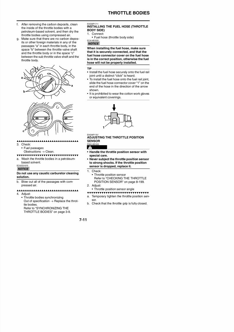
8/21/2019 Fz8 - Service Manual
http://slidepdf.com/reader/full/fz8-service-manual 384/609
a. Wash the throttle bodies in a petroleum-based solvent.
• Never subject the throttle position sensorto strong shocks. If the throttle position
THROTTLE BODIES
c. Connect the throttle position sensor, sub-
throttle position sensor and sub-throttleservo motor to the wire harness.
d. Set the main switch to “OFF” and set theengine stop switch to “ ”.
e. Simultaneously press and hold the“SELECT” and “RESET” buttons “1”, setthe main switch to “ON”, and continue topress the buttons for 8 seconds more.
TIP
• All displays on the meter disappear exceptthe clock and odometer/tripmeter/fuel
reserve tripmeter displays.• “dI” appears on the clock LCD “2”.
f. Diagnostic code number “D:01” is selected.g. Adjust the position of the throttle position
sensor angle so that 14–20 can appear inthe meter.
h. After adjusting the throttle position sensorangle, tighten the throttle position sensorscrews “1”.
EAS39P1708
ADJUSTING THE SUB-THROTTLE POSI-TION SENSOR
WARNING
EWA39P1701
• Handle the sub-throttle position sensorwith special care.
• Never subject the sub-throttle positionsensor to strong shocks. If the sub-throt-
tle position sensor is dropped, replace it.1. Check:
• Sub-throttle position sensorRefer to “CHECKING THE SUB-THROT-TLE POSITION SENSOR” on page 8-199.
2. Adjust:• Sub-throttle position sensor angle
a. Remove the throttle bodies and temporarytighten the sub-throttle position sensor.
b. Connect the test harness sub-throttle posi-tion sensor (3P) “1” to the sub-throttle posi-tion sensor and wire harness as shown.
ECA39P1705
Pay attention to the installing direction ofthe test harness sub-throttle position sen-
sor coupler “a”.
Throttle position sensor screw3.5 Nm (0.35 m·kgf, 2.5 ft·lbf)
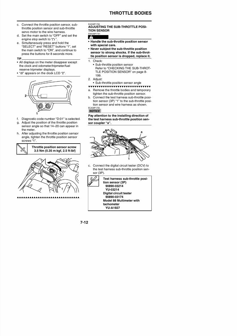
8/21/2019 Fz8 - Service Manual
http://slidepdf.com/reader/full/fz8-service-manual 385/609
c. Connect the digital circuit tester (DCV) to
THROTTLE BODIES
d. Set the main switch to “ON” and fully closethe sub-throttle valves.
e. Measure the sub-throttle position sensorvoltage.
f. Adjust the sub-throttle position sensorangle so that the voltage is within the spec-ified range.
g. After adjusting the sub-throttle position
sensor angle, tighten the sub-throttle posi-tion sensor screw “2”.
h. Remove the test harness sub-throttle posi-tion sensor (3P) and install the throttle bod-ies.
• Positive tester probeGreen/yellow (wire harness color)
• Negative tester probeBlack/blue (wire harness color)
Output voltage0.3–0.4 V
Sub-throttle position sensorscrew
3.5 Nm (0.35 m·kgf, 2.5 ft·lbf)
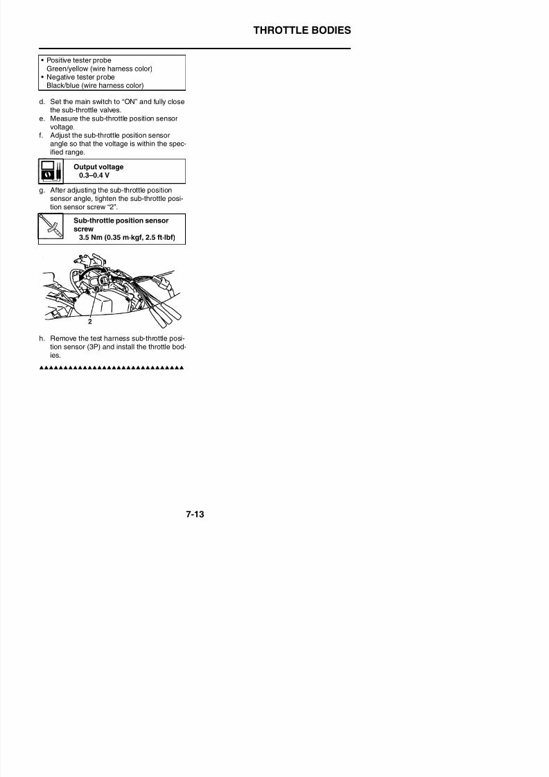
8/21/2019 Fz8 - Service Manual
http://slidepdf.com/reader/full/fz8-service-manual 386/609
THROTTLE BODIES

8/21/2019 Fz8 - Service Manual
http://slidepdf.com/reader/full/fz8-service-manual 387/609
AIR INDUCTION SYSTEM
EAS27040
AIR INDUCTION SYSTEM
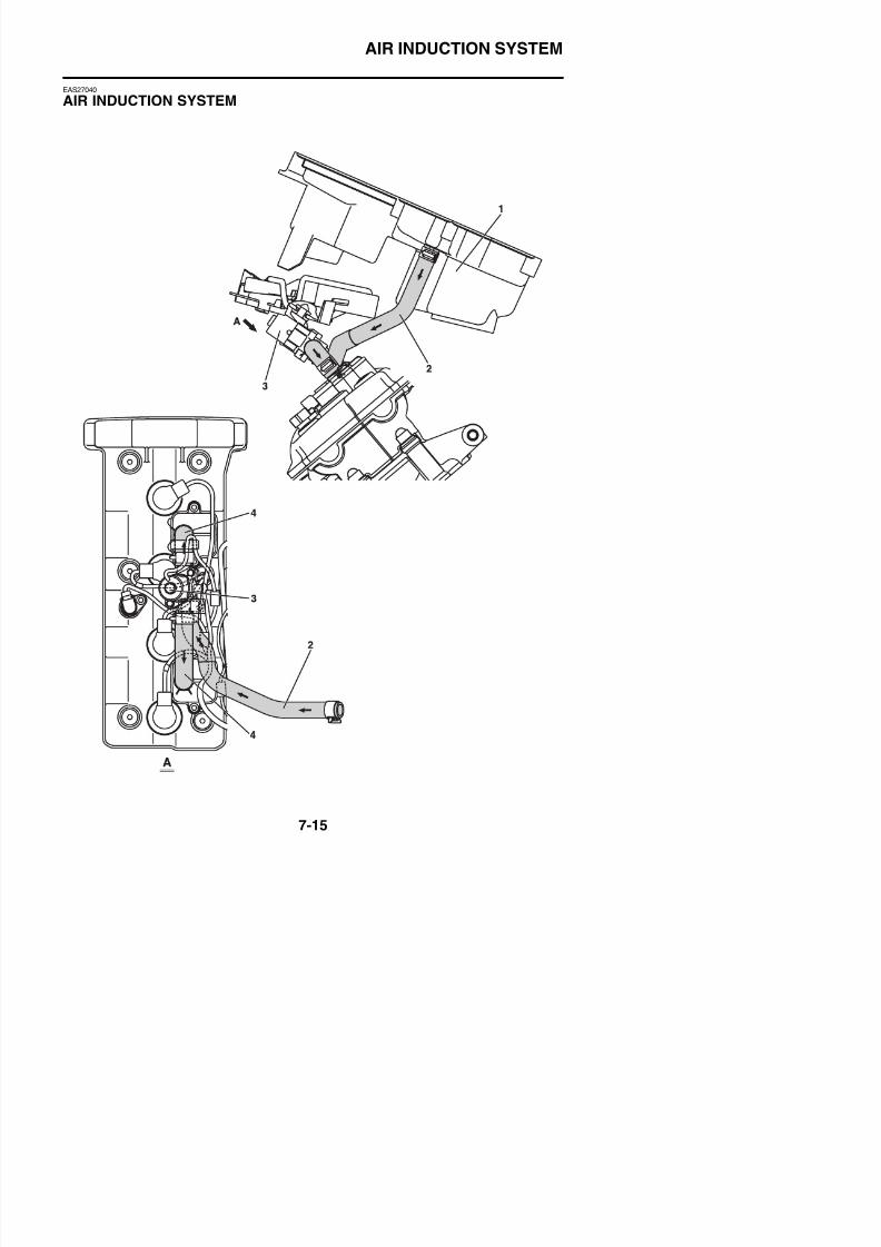
8/21/2019 Fz8 - Service Manual
http://slidepdf.com/reader/full/fz8-service-manual 388/609
AIR INDUCTION SYSTEM
1. Air filter case
2. Air induction system hose (air filter case toair cut-off valve)
3. Air cut-off valve
4. Air induction system hose (air cut-off valveto reed valve cover)
8/21/2019 Fz8 - Service Manual
http://slidepdf.com/reader/full/fz8-service-manual 389/609
AIR INDUCTION SYSTEM
Removing the air cut-off valve assembly and reed valves
Order Job/Parts to remove Q’ty Remarks
Rider seat Refer to “GENERAL CHASSIS” on page 4-1.
Inner panel/side panel/front cowling side panelFZ8SA
Refer to “GENERAL CHASSIS” on page 4-1.
Fuel tank Refer to “FUEL TANK” on page 7-1.
Air filter case Refer to “GENERAL CHASSIS” on page 4-1.
Radiator Refer to “RADIATOR” on page 6-1.
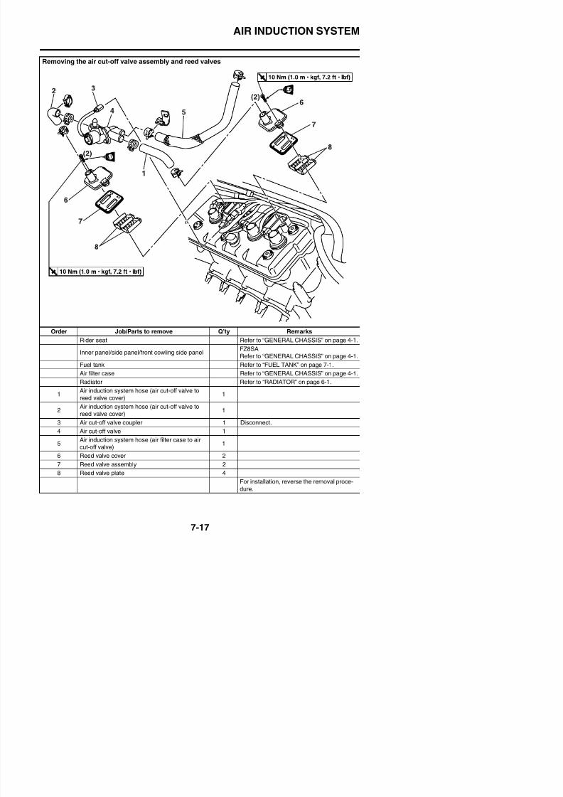
8/21/2019 Fz8 - Service Manual
http://slidepdf.com/reader/full/fz8-service-manual 390/609
1Air induction system hose (air cut-off valve to
1
AIR INDUCTION SYSTEM
EAS27060
CHECKING THE AIR INDUCTION SYSTEM
Air injectionThe air induction system burns unburnedexhaust gases by injecting fresh air (second-ary air) into the exhaust port, reducing theemission of hydrocarbons. When there is neg-ative pressure at the exhaust port, the reedvalve opens, allowing secondary air to flow into
the exhaust port. The required temperature forburning the unburned exhaust gases isapproximately 600 to 700 °C (1112 to 1292°F).
Air cut-off valveThe air cut-off valve is controlled by the signalsfrom the ECU in accordance with the combus-
tion conditions. Ordinarily, the air cut-off valveopens to allow the air to flow during idle and
closes to cut-off the flow when the vehicle isbeing driven. However, if the coolant tempera-ture is below the specified value, the air cut-offvalve remains open and allows the air to flowinto the exhaust pipe until the temperaturebecomes higher than the specified value.
1. Check:
• HosesLoose connections → Connect properly.Cracks/damage → Replace.
2. Check:• Reed valve• Reed valve stopper• Reed valve seat
Cracks/damage → Replace the reed
valve assembly.3. Measure:
• Reed valve bending limit “a”Out of specification → Replace the reedvalve assembly.
4. Check:• Air cut-off valve
Cracks/damage → Replace.5. Check
• Air induction system solenoid
Refer to “CHECKING THE AIR INDUC-TION SYSTEM SOLENOID” on page 8-200.
EAS39P1712
INSTALLING THE AIR INDUCTION SYSTEM
Reed valve bending limit0.4 mm (0.016 in)
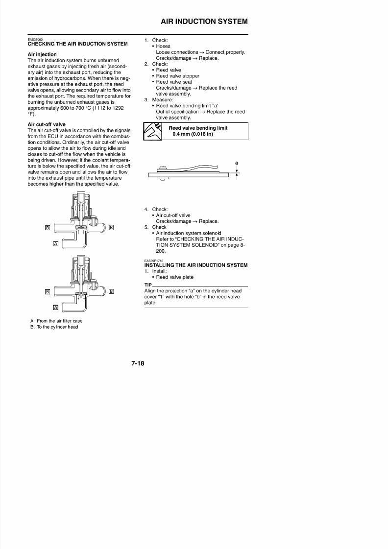
8/21/2019 Fz8 - Service Manual
http://slidepdf.com/reader/full/fz8-service-manual 391/609
1 Install:
AIR INDUCTION SYSTEM
• Reed valve assembly
TIP
Install the reed valve assembly so that theopen side turns to the exhaust side of theengine.
2. Install:• Reed valve cover
A. Exhaust side
Reed valve cover bolt10 Nm (1.0 m·kgf, 7.2 ft·lbf)LOCTITE®
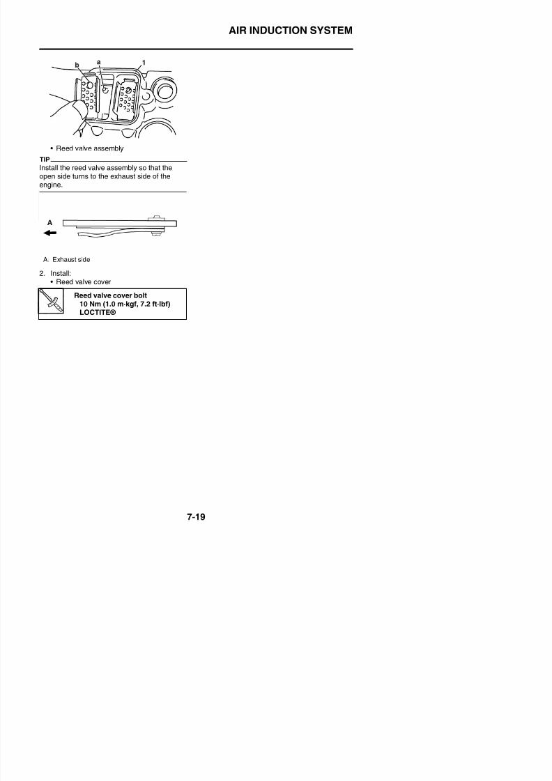
8/21/2019 Fz8 - Service Manual
http://slidepdf.com/reader/full/fz8-service-manual 392/609
ELECTRICAL SYSTEM
IGNITION SYSTEM.......................................................................................8-1CIRCUIT DIAGRAM................................................................................8-1ENGINE STOPPING DUE TO SIDESTAND OPERATION .....................8-5TROUBLESHOOTING............................................................................8-7
ELECTRIC STARTING SYSTEM................................................................8-11CIRCUIT DIAGRAM..............................................................................8-11STARTING CIRCUIT CUT-OFF SYSTEM OPERATION.......................8-15TROUBLESHOOTING..........................................................................8-17
CHARGING SYSTEM .................................................................................8-19CIRCUIT DIAGRAM..............................................................................8-19TROUBLESHOOTING..........................................................................8-23
LIGHTING SYSTEM ...................................................................................8-25CIRCUIT DIAGRAM..............................................................................8-25TROUBLESHOOTING..........................................................................8-29
SIGNALING SYSTEM.................................................................................8-31CIRCUIT DIAGRAM..............................................................................8-31
TROUBLESHOOTING..........................................................................8-35
COOLING SYSTEM....................................................................................8-41CIRCUIT DIAGRAM..............................................................................8-41TROUBLESHOOTING..........................................................................8-45
FUEL INJECTION SYSTEM .......................................................................8-47
CIRCUIT DIAGRAM..............................................................................8-47ECU SELF-DIAGNOSTIC FUNCTION .................................................8-51TROUBLESHOOTING METHOD .........................................................8-53DIAGNOSTIC MODE............................................................................8-54TROUBLESHOOTING DETAILS ..........................................................8-55DIAGNOSTIC CODE TABLE ..............................................................8-107
8/21/2019 Fz8 - Service Manual
http://slidepdf.com/reader/full/fz8-service-manual 393/609
G OS C CO 8 0
ABS (ANTI-LOCK BRAKE SYSTEM) ......................................................8-127
CIRCUIT DIAGRAM............................................................................8-127ABS COMPONENTS CHART.............................................................8-131ABS COUPLER LOCATION CHART ..................................................8-133MAINTENANCE OF THE ABS ECU...................................................8-135ABS TROUBLESHOOTING OUTLINE ...............................................8-135BASIC INSTRUCTIONS FOR TROUBLESHOOTING........................8-136BASIC PROCESS FOR TROUBLESHOOTING................................. 8-137[A] CHECKING THE ABS WARNING LIGHT .....................................8-138
[B-1] THE ABS WARNING LIGHT FAILS TO COME ON ...................8-138[B-2] THE ABS WARNING LIGHT FLASHES.....................................8-138[B-3] THE ABS WARNING LIGHT REMAINS ON .............................. 8-138[B-4] THE ABS WARNING LIGHT COMES ON FOR 2 SECONDS,THEN GOES OFF .............................................................................. 8-139[B-5] MALFUNCTION ARE CURRENTLY DETECTED......................8-140[C-1] ONLY THE ABS WARNING LIGHT FAILS TO COME ON.........8-140[C-2] ALL INDICATOR LIGHTS FAIL TO COME ON.......................... 8-140
[C-3] THE ABS WARNING LIGHT REMAINS ON.............................. 8-141[C-4] THE ABS WARNING LIGHT FLASHES .................................... 8-141[C-5] DIAGNOSIS USING THE FAULT CODES ................................. 8-142[D-1] DELETING THE FAULT CODES................................................8-172
[D-2] DELETE FUNCTION TEST .......................................................8-172[D-3] FINAL CHECK ........................................................................... 8-174
ELECTRICAL COMPONENTS .................................................................8-175
CHECKING THE SWITCHES.............................................................8-179CHECKING THE BULBS AND BULB SOCKETS...............................8-184CHECKING THE FUSES....................................................................8-185CHECKING AND CHARGING THE BATTERY...................................8-186CHECKING THE RELAYS..................................................................8-189CHECKING THE TURN SIGNAL/HAZARD RELAY ........................... 8-190CHECKING THE RELAY UNIT (DIODE) ............................................8-191CHECKING THE IGNITION COILS....................................................8-192
CHECKING THE CRANKSHAFT POSITION SENSOR.....................8-193CHECKING THE LEAN ANGLE SENSOR.........................................8-194CHECKING THE STARTER MOTOR OPERATION............................ 8-194CHECKING THE STATOR COIL......................................................... 8-195CHECKING THE RECTIFIER/REGULATOR......................................8-195CHECKING THE HORN 8-196
8/21/2019 Fz8 - Service Manual
http://slidepdf.com/reader/full/fz8-service-manual 394/609
CHECKING THE HORN ..................................................................... 8 196

8/21/2019 Fz8 - Service Manual
http://slidepdf.com/reader/full/fz8-service-manual 395/609
IGNITION SYSTEM
EAS27090
IGNITION SYSTEMEAS27110
CIRCUIT DIAGRAM
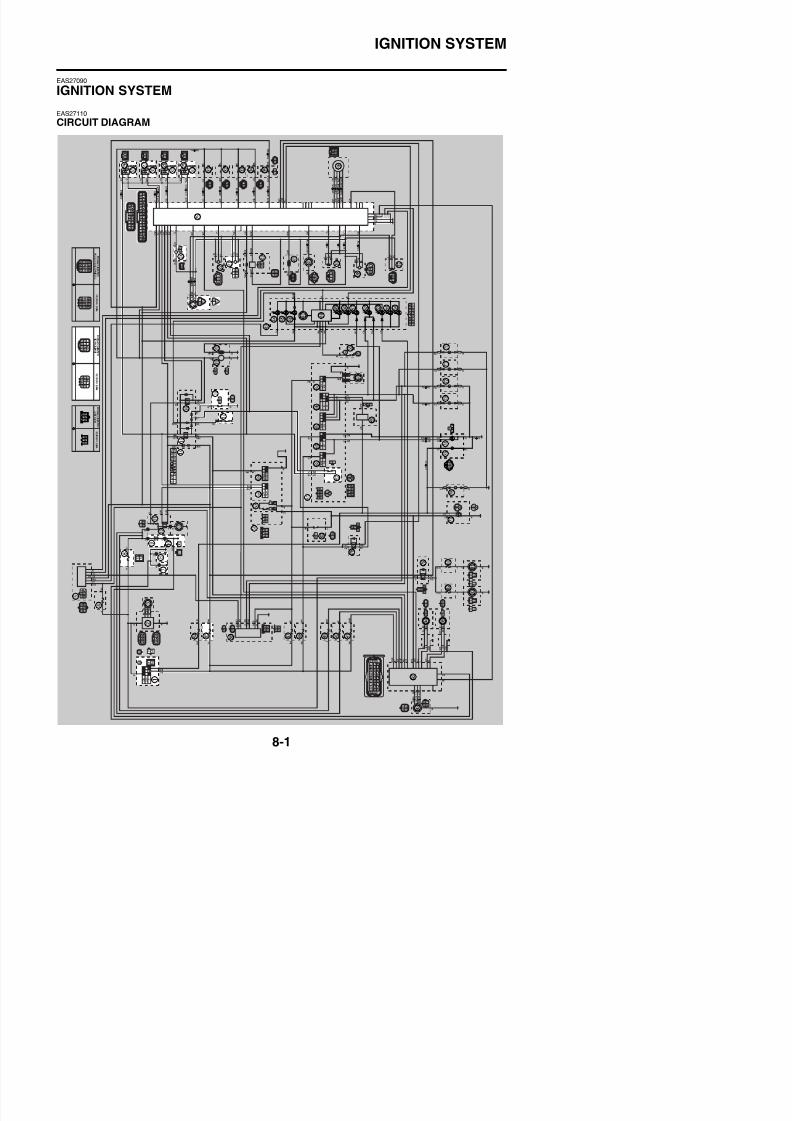
8/21/2019 Fz8 - Service Manual
http://slidepdf.com/reader/full/fz8-service-manual 396/609
IGNITION SYSTEM
FZ8NA
1. Main switch6. Main fuse
7. Frame ground
8. Engine ground
9. Battery
10.Negative battery ground lead
14.Relay unit
15.Starting circuit cut-off relay
17.Neutral switch
18.Sidestand switch
21.Lean angle sensor
23.Cylinder identification sensor
24.Crankshaft position sensor
25.ECU (engine control unit)
26.Ignition coil #1
27.Ignition coil #2
28.Ignition coil #3
29.Ignition coil #4
30.Spark plug
56.Right handlebar switch
58.Engine stop switch
61.Left handlebar switch
62.Clutch switch
85.Ignition fuse
8/21/2019 Fz8 - Service Manual
http://slidepdf.com/reader/full/fz8-service-manual 397/609
IGNITION SYSTEM
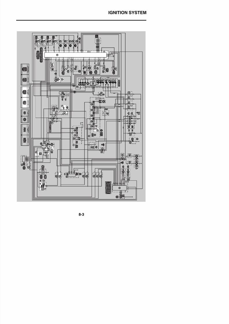
8/21/2019 Fz8 - Service Manual
http://slidepdf.com/reader/full/fz8-service-manual 398/609
IGNITION SYSTEM
FZ8SA1. Main switch
6. Main fuse
7. Frame ground
8. Engine ground
9. Battery
10.Negative battery ground lead
14.Relay unit
15.Starting circuit cut-off relay
17.Neutral switch
18.Sidestand switch
21.Lean angle sensor
23.Cylinder identification sensor
24.Crankshaft position sensor
25.ECU (engine control unit)
26.Ignition coil #1
27.Ignition coil #2
28.Ignition coil #3
29.Ignition coil #4
30.Spark plug
56.Right handlebar switch
58.Engine stop switch
61.Left handlebar switch
62.Clutch switch
86.Ignition fuse

8/21/2019 Fz8 - Service Manual
http://slidepdf.com/reader/full/fz8-service-manual 399/609
IGNITION SYSTEM
EAS39P1804
ENGINE STOPPING DUE TO SIDESTAND OPERATION
When the engine is running and the transmission is in gear, the engine will stop if the sidestand ismoved down. This is because the electric current from the ignition coils does not flow to the ECUwhen both the neutral switch and sidestand switch are set to “OFF”, thereby preventing the sparkplugs from producing a spark. However, the engine continues to run under the following conditions:• The transmission is in gear (the neutral switch circuit is open) and the sidestand is up (the side-
stand switch circuit is closed).
• The transmission is in neutral (the neutral switch circuit is closed) and the sidestand is down (thesidestand switch circuit is open).
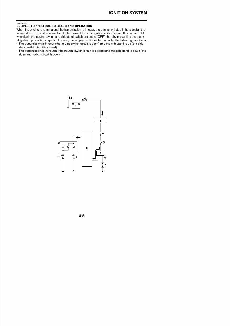
8/21/2019 Fz8 - Service Manual
http://slidepdf.com/reader/full/fz8-service-manual 400/609
IGNITION SYSTEM
1. Battery
2. Main fuse3. Main switch
4. Ignition fuse
5. Engine stop switch
6. Ignition coil
7. Spark plug
8. ECU (engine control unit)
9. Sidestand switch
10.Relay unit (diode)11.Neutral switch
12.Battery negative lead
8/21/2019 Fz8 - Service Manual
http://slidepdf.com/reader/full/fz8-service-manual 401/609
IGNITION SYSTEM
EAS27150
TROUBLESHOOTING
The ignition system fails to operate (no spark or intermittent spark).
TIP
• Before troubleshooting, remove the following part(s):1. Rider seat2. Passenger seat
3. Left inner panel (FZ8SA)4. Right inner panel (FZ8SA)
5. Left side panel (FZ8SA)6. Right side panel (FZ8SA)7. Front cowling (FZ8SA)8. Fuel tank9. Radiator
NG→
OK↓
NG→
OK↓
NG→
OK↓
OK→
NG↓
NG→
1. Check the fuses.(Main and ignition)
Refer to “CHECKING THE FUSES”on page 8-185.
Replace the fuse(s).
2. Check the battery.Refer to “CHECKING ANDCHARGING THE BATTERY” on
page 8-186.
• Clean the battery terminals.• Recharge or replace the battery.
3. Check the spark plugs.Refer to “CHECKING THE SPARK
PLUGS” on page 3-4.
Re-gap or replace the spark plugs.
4. Check the ignition spark gap.Refer to “CHECKING THE IGNI-
TION COILS” on page 8-192.
Ignition system is OK.
5. Check the ignition coils.
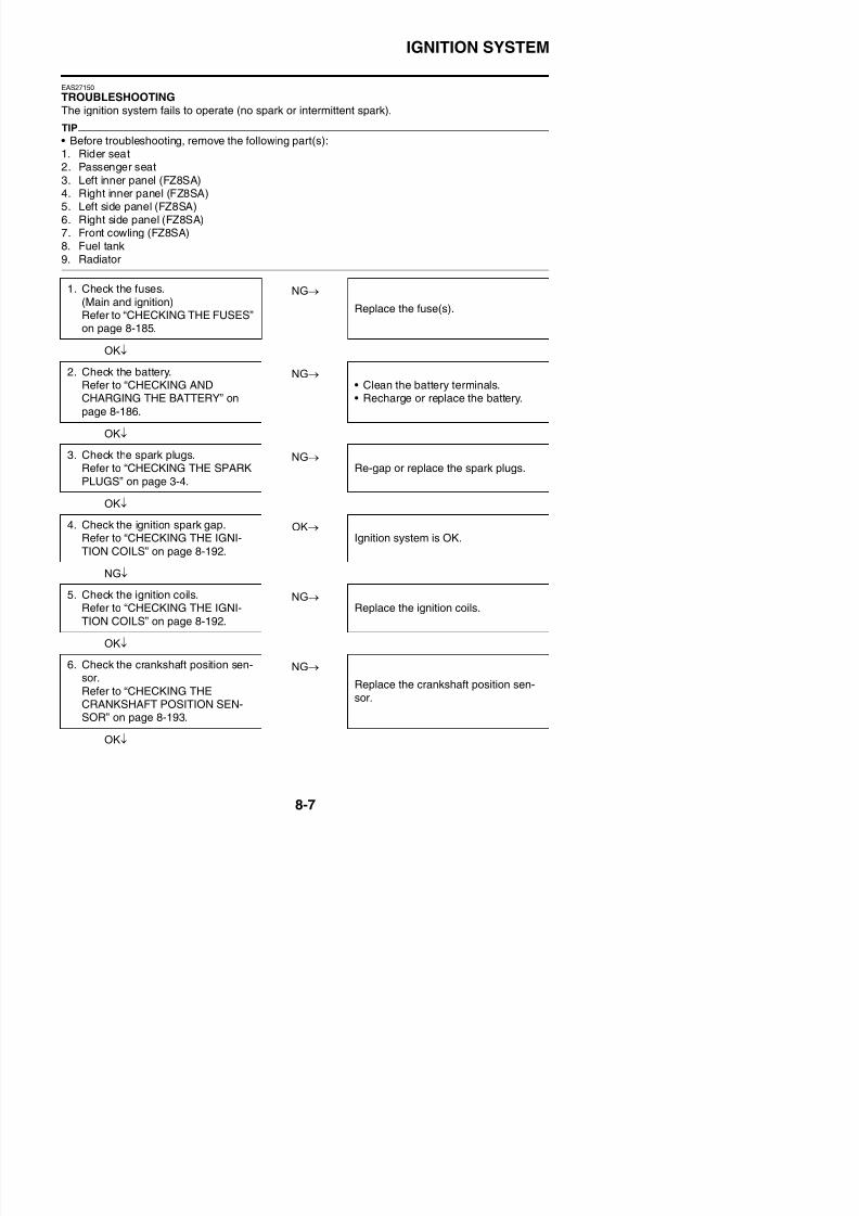
8/21/2019 Fz8 - Service Manual
http://slidepdf.com/reader/full/fz8-service-manual 402/609
IGNITION SYSTEM
NG→
OK↓
NG→
OK↓
NG→
OK↓
NG→
OK↓
NG→
OK↓
NG→
OK↓
NG→
OK↓
7. Check the cylinder identification
sensor.Refer to “CHECKING THE CYLIN-DER IDENTIFICATION SENSOR”on page 8-201.
Replace the cylinder identificationsensor.
8. Check the main switch.Refer to “CHECKING THESWITCHES” on page 8-179.
Replace the main switch/immobilizer
unit.
9. Check the engine stop switch.Refer to “CHECKING THESWITCHES” on page 8-179.
Replace the right handlebar switch.
10.Check the neutral switch.Refer to “CHECKING THESWITCHES” on page 8-179.
Replace the neutral switch.
11.Check the sidestand switch.Refer to “CHECKING THESWITCHES” on page 8-179.
Replace the sidestand switch.
12.Check the clutch switch.Refer to “CHECKING THESWITCHES” on page 8-179.
Replace the clutch switch.
13.Check the relay unit (starting circuitcut-off relay).Refer to “CHECKING THERELAYS” on page 8-189.
Replace the relay unit.
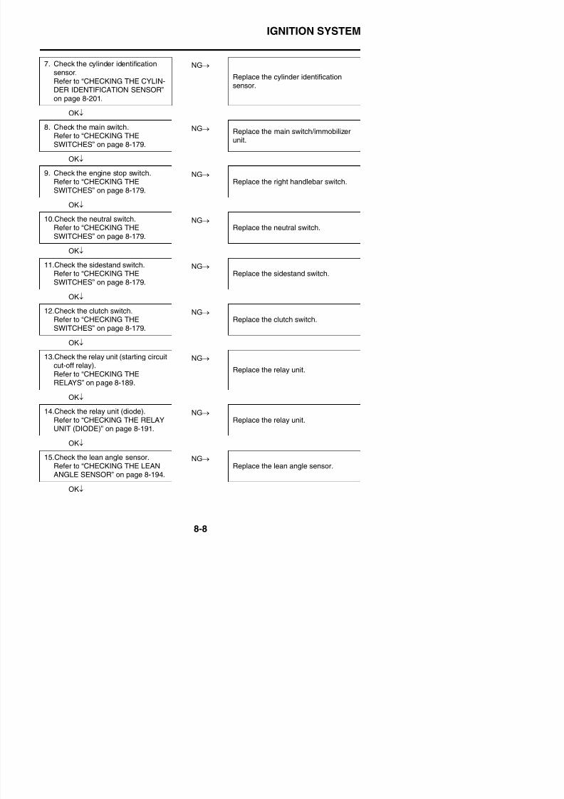
8/21/2019 Fz8 - Service Manual
http://slidepdf.com/reader/full/fz8-service-manual 403/609
IGNITION SYSTEM
NG→
OK↓
16.Check the entire ignition system’s
wiring.Refer to “CIRCUIT DIAGRAM” onpage 8-1.
Properly connect or repair the ignitionsystem’s wiring.
Replace the ECU.
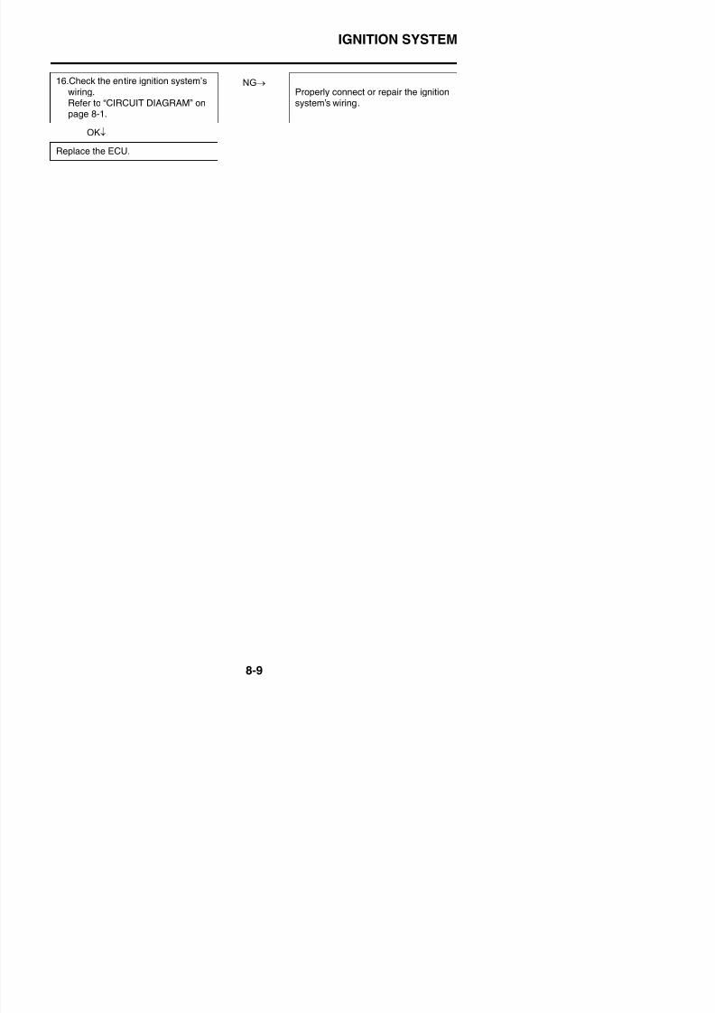
8/21/2019 Fz8 - Service Manual
http://slidepdf.com/reader/full/fz8-service-manual 404/609
IGNITION SYSTEM

8/21/2019 Fz8 - Service Manual
http://slidepdf.com/reader/full/fz8-service-manual 405/609
ELECTRIC STARTING SYSTEM
EAS27160
ELECTRIC STARTING SYSTEM
EAS27170
CIRCUIT DIAGRAM
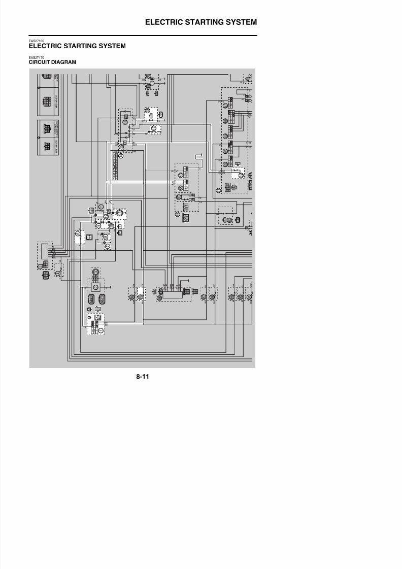
8/21/2019 Fz8 - Service Manual
http://slidepdf.com/reader/full/fz8-service-manual 406/609
ELECTRIC STARTING SYSTEM
FZ8NA1. Main switch
6. Main fuse
7. Frame ground
8. Engine ground
9. Battery
10.Negative battery ground lead
12.Starter relay
13.Starter motor
14.Relay unit
15.Starting circuit cut-off relay
17.Neutral switch
18.Sidestand switch
56.Right handlebar switch
58.Engine stop switch
59.Start switch
61.Left handlebar switch
62.Clutch switch
85.Ignition fuse
8/21/2019 Fz8 - Service Manual
http://slidepdf.com/reader/full/fz8-service-manual 407/609
ELECTRIC STARTING SYSTEM
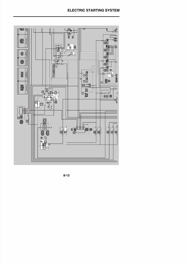
8/21/2019 Fz8 - Service Manual
http://slidepdf.com/reader/full/fz8-service-manual 408/609
ELECTRIC STARTING SYSTEM
FZ8SA1. Main switch
6. Main fuse
7. Frame ground
8. Engine ground
9. Battery
10.Negative battery ground lead
12.Starter relay
13.Starter motor
14.Relay unit
15.Starting circuit cut-off relay
17.Neutral switch
18.Sidestand switch
56.Right handlebar switch
58.Engine stop switch
59.Start switch
61.Left handlebar switch
62.Clutch switch
86.Ignition fuse

8/21/2019 Fz8 - Service Manual
http://slidepdf.com/reader/full/fz8-service-manual 409/609
ELECTRIC STARTING SYSTEM
EAS27180
STARTING CIRCUIT CUT-OFF SYSTEM OPERATION
If the engine stop switch is set to “ ” and the main switch is set to “ON” (both switches are closed),the starter motor can only operate if at least one of the following conditions is met:• The transmission is in neutral (the neutral switch is closed).• The clutch lever is pulled to the handlebar (the clutch switch is closed) and the sidestand is up (the
sidestand switch is closed).The starting circuit cut-off relay prevents the starter motor from operating when neither of these con-ditions has been met. In this instance, the starting circuit cut-off relay is open so current cannot
reach the starter motor. When at least one of the above conditions has been met the starting circuit
cut-off relay is closed and the engine can be started by pressing the starter switch.
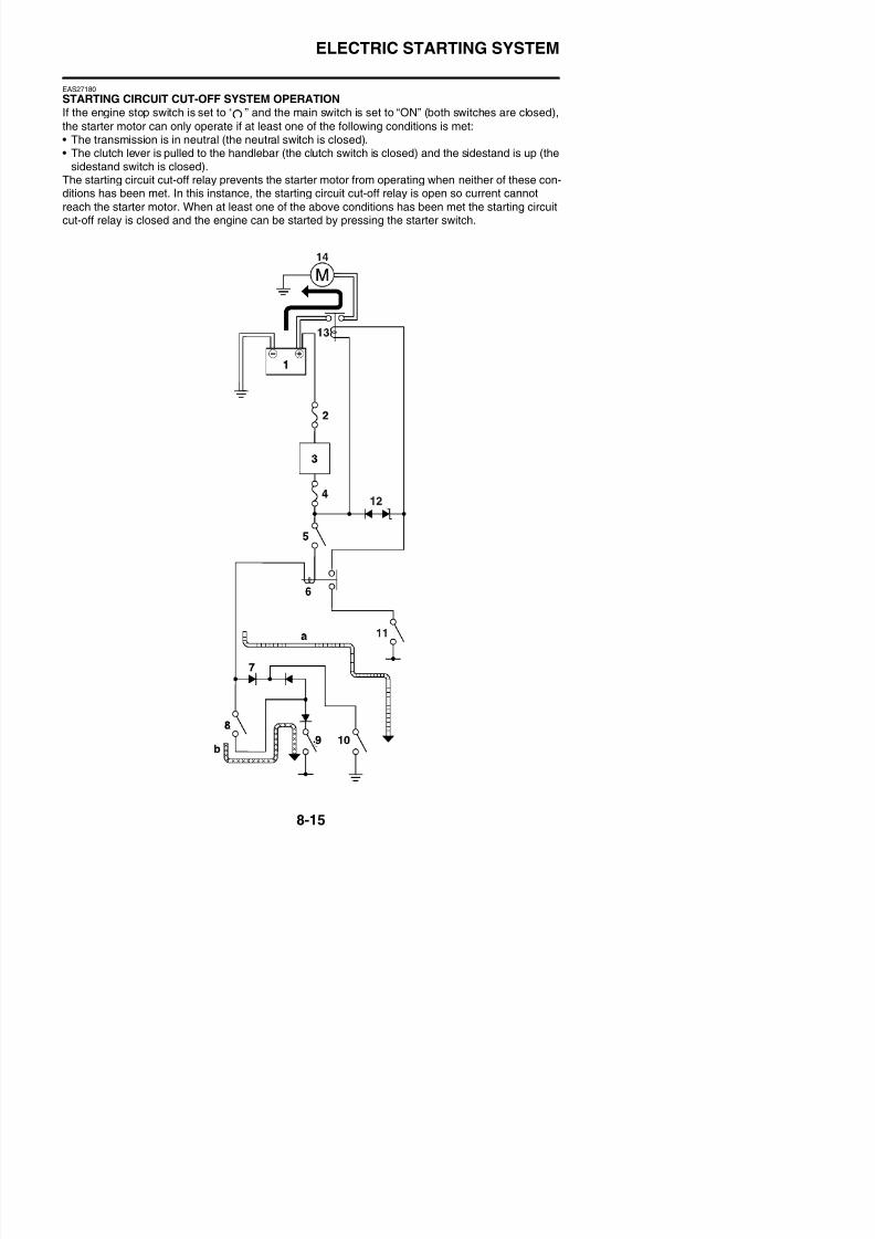
8/21/2019 Fz8 - Service Manual
http://slidepdf.com/reader/full/fz8-service-manual 410/609
ELECTRIC STARTING SYSTEM
a. WHEN THE TRANSMISSION IS IN NEU-TRAL
b. WHEN THE SIDESTAND IS UP AND THECLUTCH LEVER IS PULLED TO THEHANDLEBAR
1. Battery
2. Main fuse
3. Main switch
4. Ignition fuse
5. Engine stop switch6. Starting circuit cut-off relay
7. Diode
8. Clutch switch
9. Sidestand switch
10.Neutral switch
11.Start switch
12.Diode
13.Starter relay14.Starter motor
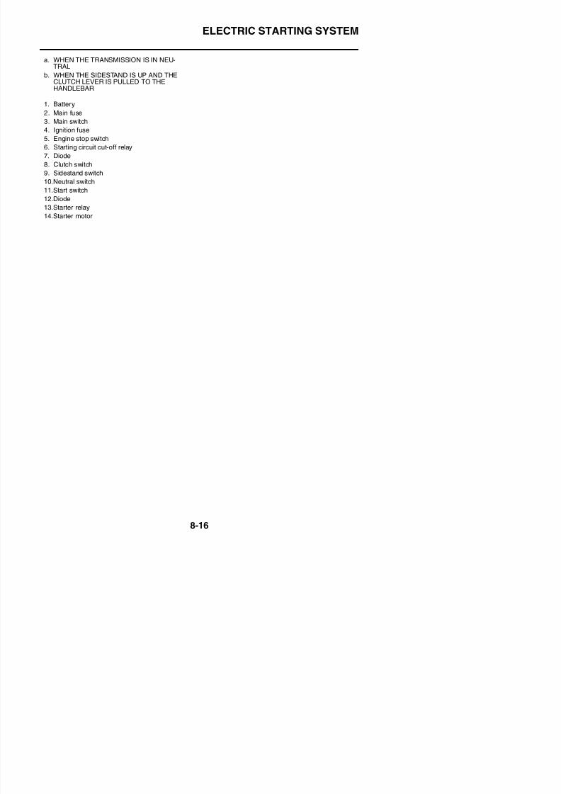
8/21/2019 Fz8 - Service Manual
http://slidepdf.com/reader/full/fz8-service-manual 411/609
ELECTRIC STARTING SYSTEM
EAS27190
TROUBLESHOOTING
The starter motor fails to turn.
TIP
• Before troubleshooting, remove the following part(s):1. Rider seat2. Passenger seat
3. Left inner panel (FZ8SA)4. Right inner panel (FZ8SA)5. Left side panel (FZ8SA)6. Right side panel (FZ8SA)7. Front cowling (FZ8SA)8. Fuel tank9. Air filter case10. Throttle bodies
NG→
OK↓
NG→
OK↓
OK→
NG↓
NG→
OK↓
1. Check the fuses.
(Main and ignition)Refer to “CHECKING THE FUSES”
on page 8-185.
Replace the fuse(s).
2. Check the battery.Refer to “CHECKING AND
CHARGING THE BATTERY” on
page 8-186.
• Clean the battery terminals.
• Recharge or replace the battery.
3. Check the starter motor operation.
Refer to “CHECKING THESTARTER MOTOR OPERATION”on page 8-194.
Starter motor is OK. Perform the elec-tric starting system troubleshooting,starting with step 5.
4. Check the starter motor.Refer to “CHECKING THESTARTER MOTOR” on page 5-43.
Repair or replace the starter motor.
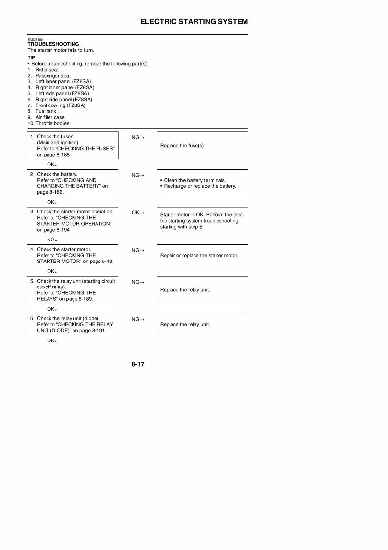
8/21/2019 Fz8 - Service Manual
http://slidepdf.com/reader/full/fz8-service-manual 412/609
ELECTRIC STARTING SYSTEM
NG→
OK↓
NG→
OK↓
NG→
OK↓
NG→
OK↓
NG→
OK↓
NG→
OK↓
NG→
OK↓
NG→
7. Check the starter relay.
Refer to “CHECKING THERELAYS” on page 8-189.
Replace the starter relay.
8. Check the main switch.Refer to “CHECKING THESWITCHES” on page 8-179.
Replace the main switch/immobilizer
unit.
9. Check the engine stop switch.Refer to “CHECKING THESWITCHES” on page 8-179.
Replace the right handlebar switch.
10.Check the neutral switch.
Refer to “CHECKING THESWITCHES” on page 8-179.
Replace the neutral switch.
11.Check the sidestand switch.Refer to “CHECKING THESWITCHES” on page 8-179.
Replace the sidestand switch.
12.Check the clutch switch.Refer to “CHECKING THESWITCHES” on page 8-179.
Replace the clutch switch.
13.Check the start switch.
Refer to “CHECKING THESWITCHES” on page 8-179.
Replace the right handlebar switch.
14.Check the entire starting system’swiring. Properly connect or repair the starting
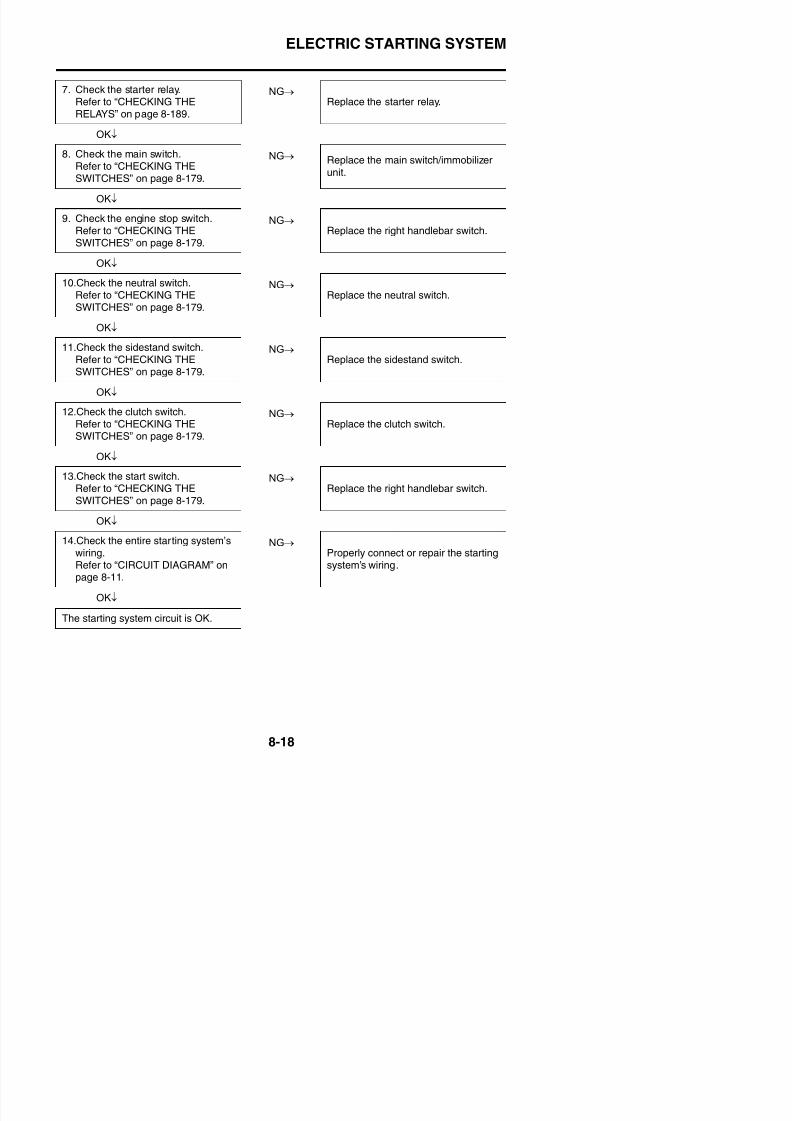
8/21/2019 Fz8 - Service Manual
http://slidepdf.com/reader/full/fz8-service-manual 413/609
CHARGING SYSTEM
EAS27200
CHARGING SYSTEM
EAS27210
CIRCUIT DIAGRAM
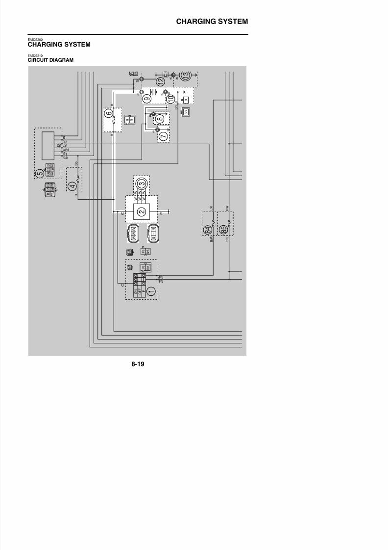
8/21/2019 Fz8 - Service Manual
http://slidepdf.com/reader/full/fz8-service-manual 414/609
CHARGING SYSTEM
FZ8NA2. Rectifier/regulator
3. AC magneto6. Main fuse
7. Frame ground
8. Engine ground
9. Battery
10.Negative battery ground lead

8/21/2019 Fz8 - Service Manual
http://slidepdf.com/reader/full/fz8-service-manual 415/609
CHARGING SYSTEM
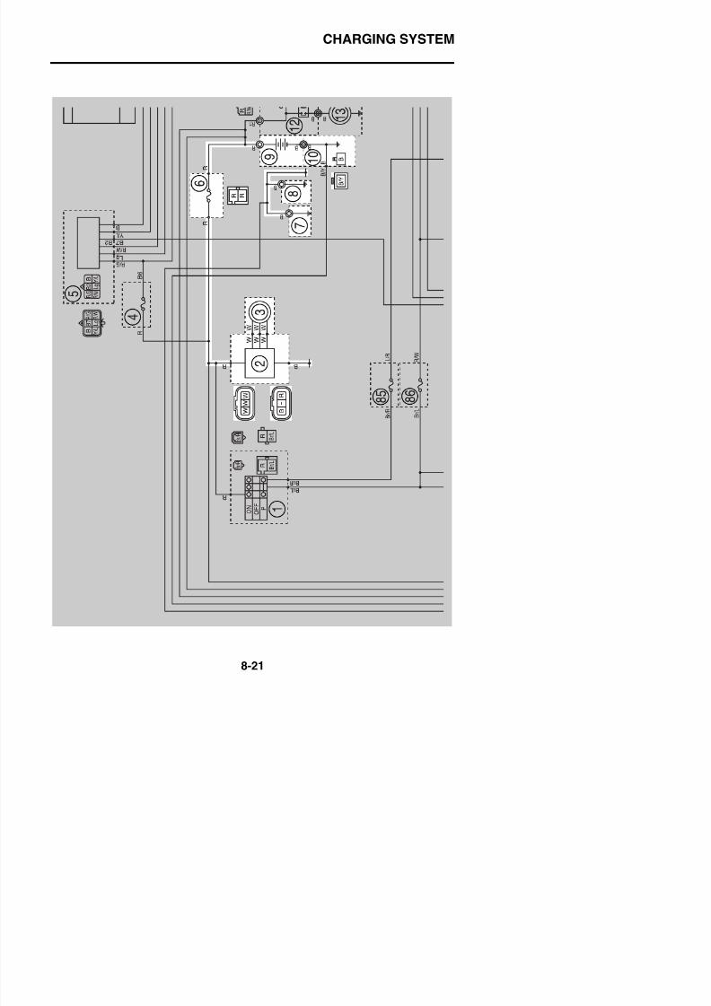
8/21/2019 Fz8 - Service Manual
http://slidepdf.com/reader/full/fz8-service-manual 416/609
CHARGING SYSTEM
FZ8SA2. Rectifier/regulator
3. AC magneto6. Main fuse
7. Frame ground
8. Engine ground
9. Battery
10.Negative battery ground lead
8/21/2019 Fz8 - Service Manual
http://slidepdf.com/reader/full/fz8-service-manual 417/609
CHARGING SYSTEM
EAS27230
TROUBLESHOOTING
The battery is not being charged.TIP
• Before troubleshooting, remove the following part(s):1. Rider seat2. Passenger seat
NG→
OK↓
NG→
OK↓
NG→
OK↓
NG→
OK↓
NG→
OK↓
1. Check the fuse.(Main)Refer to “CHECKING THE FUSES”on page 8-185.
Replace the fuse.
2. Check the battery.Refer to “CHECKING ANDCHARGING THE BATTERY” on
page 8-186.
• Clean the battery terminals.• Recharge or replace the battery.
3. Check the stator coil.Refer to “CHECKING THE STATORCOIL” on page 8-195.
Replace the stator coil assembly.
4. Check the rectifier/regulator.Refer to “CHECKING THE RECTI-FIER/REGULATOR” on page 8-195.
Replace the rectifier/regulator.
5. Check the entire charging system’s
wiring.Refer to “CIRCUIT DIAGRAM” onpage 8-19.
Properly connect or repair the charg-ing system’s wiring.
The charging system circuit is OK.
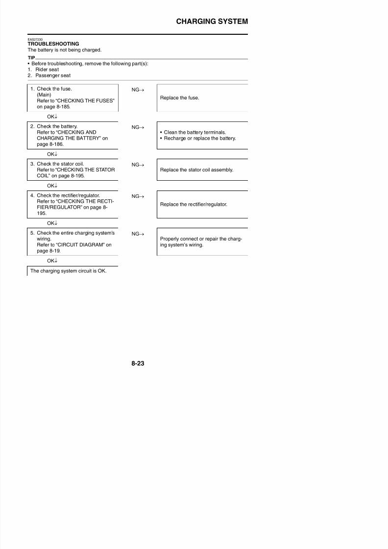
8/21/2019 Fz8 - Service Manual
http://slidepdf.com/reader/full/fz8-service-manual 418/609
CHARGING SYSTEM

8/21/2019 Fz8 - Service Manual
http://slidepdf.com/reader/full/fz8-service-manual 419/609
LIGHTING SYSTEM
EAS27240
LIGHTING SYSTEM
EAS27250
CIRCUIT DIAGRAM

8/21/2019 Fz8 - Service Manual
http://slidepdf.com/reader/full/fz8-service-manual 420/609
LIGHTING SYSTEM
FZ8NA1. Main switch
6. Main fuse7. Frame ground
8. Engine ground
9. Battery
10.Negative battery ground lead
25.ECU (engine control unit)
43.Meter assembly
51.High beam indicator light
54.Meter light61.Left handlebar switch
63.Pass switch
64.Dimmer switch
74.Headlight
75.Auxiliary light
76.License plate light
77.Tail/brake light
78.Headlight relay (on/off)84.Taillight fuse
85.Ignition fuse
88.Headlight fuse
8/21/2019 Fz8 - Service Manual
http://slidepdf.com/reader/full/fz8-service-manual 421/609
LIGHTING SYSTEM
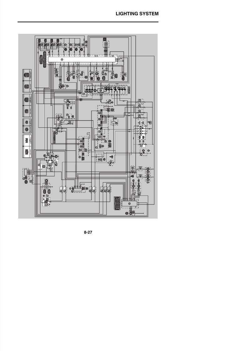
8/21/2019 Fz8 - Service Manual
http://slidepdf.com/reader/full/fz8-service-manual 422/609
LIGHTING SYSTEM
FZ8SA1. Main switch
6. Main fuse7. Frame ground
8. Engine ground
9. Battery
10.Negative battery ground lead
25.ECU (engine control unit)
43.Meter assembly
51.High beam indicator light
54.Meter light61.Left handlebar switch
63.Pass switch
64.Dimmer switch
74.Auxiliary light
75.Headlight (high beam)
76.Headlight (low beam)
77.License plate light
78.Tail/brake light79.Headlight relay (on/off)
85.Taillight fuse
86.Ignition fuse
89.Headlight fuse
8/21/2019 Fz8 - Service Manual
http://slidepdf.com/reader/full/fz8-service-manual 423/609
LIGHTING SYSTEM
EAS27260
TROUBLESHOOTING
Any of the following fail to light: headlight, high beam indicator light, taillight, license light or meterlight.
TIP
• Before troubleshooting, remove the following part(s):1. Rider seat
2. Passenger seat3. Left inner panel (FZ8SA)4. Right inner panel (FZ8SA)
5. Left side panel (FZ8SA)6. Right side panel (FZ8SA)7. Front cowling (FZ8SA)8. Headlight assembly (FZ8SA)9. Fuel tank
NG→
OK↓
NG→
OK↓
NG→
OK↓
NG→
1. Check the each bulbs and bulbsockets condition.
Refer to “CHECKING THE BULBSAND BULB SOCKETS” on page 8-184.
Replace the bulb(s) and bulbsocket(s).
2. Check the fuses.
(Main, headlight, ignition (FZ8SA)
and taillight)Refer to “CHECKING THE FUSES”on page 8-185.
Replace the fuse(s).
3. Check the battery.Refer to “CHECKING ANDCHARGING THE BATTERY” on
page 8-186.
• Clean the battery terminals.• Recharge or replace the battery.
4. Check the main switch.Refer to “CHECKING THESWITCHES” on page 8 179
Replace the main switch/immobilizerunit.
G G S S
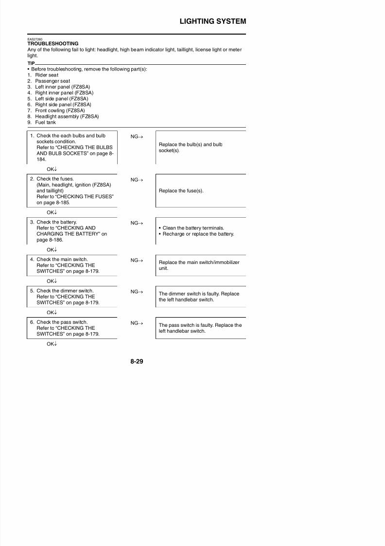
8/21/2019 Fz8 - Service Manual
http://slidepdf.com/reader/full/fz8-service-manual 424/609
LIGHTING SYSTEM
NG→
OK↓
NG→
OK↓
7. Check the headlight relay (on/off).
Refer to “CHECKING THERELAYS” on page 8-189.
Replace the headlight relay.
8. Check the entire lighting system’swiring.Refer to “CIRCUIT DIAGRAM” onpage 8-25.
Properly connect or repair the lightingsystem’s wiring.
Replace the ECU or meter assembly.
SIGNALING SYSTEM
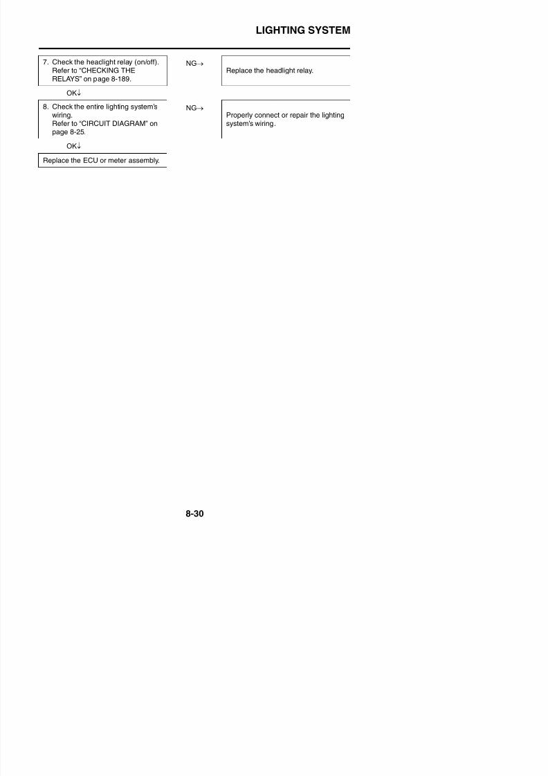
8/21/2019 Fz8 - Service Manual
http://slidepdf.com/reader/full/fz8-service-manual 425/609
SIGNALING SYSTEM
EAS27270
SIGNALING SYSTEM
EAS27280
CIRCUIT DIAGRAM
SIGNALING SYSTEM
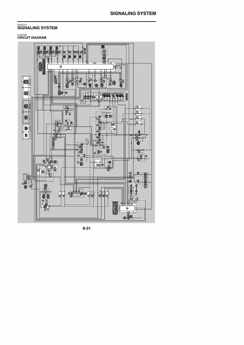
8/21/2019 Fz8 - Service Manual
http://slidepdf.com/reader/full/fz8-service-manual 426/609
SIGNALING SYSTEM
FZ8NA1. Main switch
6. Main fuse7. Frame ground
8. Engine ground
9. Battery
10.Negative battery ground lead
14.Relay unit
17.Neutral switch
20.Fuel sender
25.ECU (engine control unit)40.Coolant temperature sensor
43.Meter assembly
45.Oil level warning light
46.Neutral indicator light
47.Tachometer
48.Multi-function meter
52.Turn signal indicator light
55.Oil level switch56.Right handlebar switch
57.Front brake light switch
60.Rear brake light switch
61.Left handlebar switch
65.Hazard switch
66.Turn signal switch
67.Horn switch
68.Horn69.Turn signal/hazard relay
70.Rear right turn signal light
71.Rear left turn signal light
72.Front right turn signal light
73.Front left turn signal light
77.Tail/brake light
84.Taillight fuse
85.Ignition fuse87.Signal fuse
91.ABS ECU fuse
92.ABS ECU (electronic control unit)
95.Rear wheel sensor
SIGNALING SYSTEM
8/21/2019 Fz8 - Service Manual
http://slidepdf.com/reader/full/fz8-service-manual 427/609
SIGNALING SYSTEM
SIGNALING SYSTEM
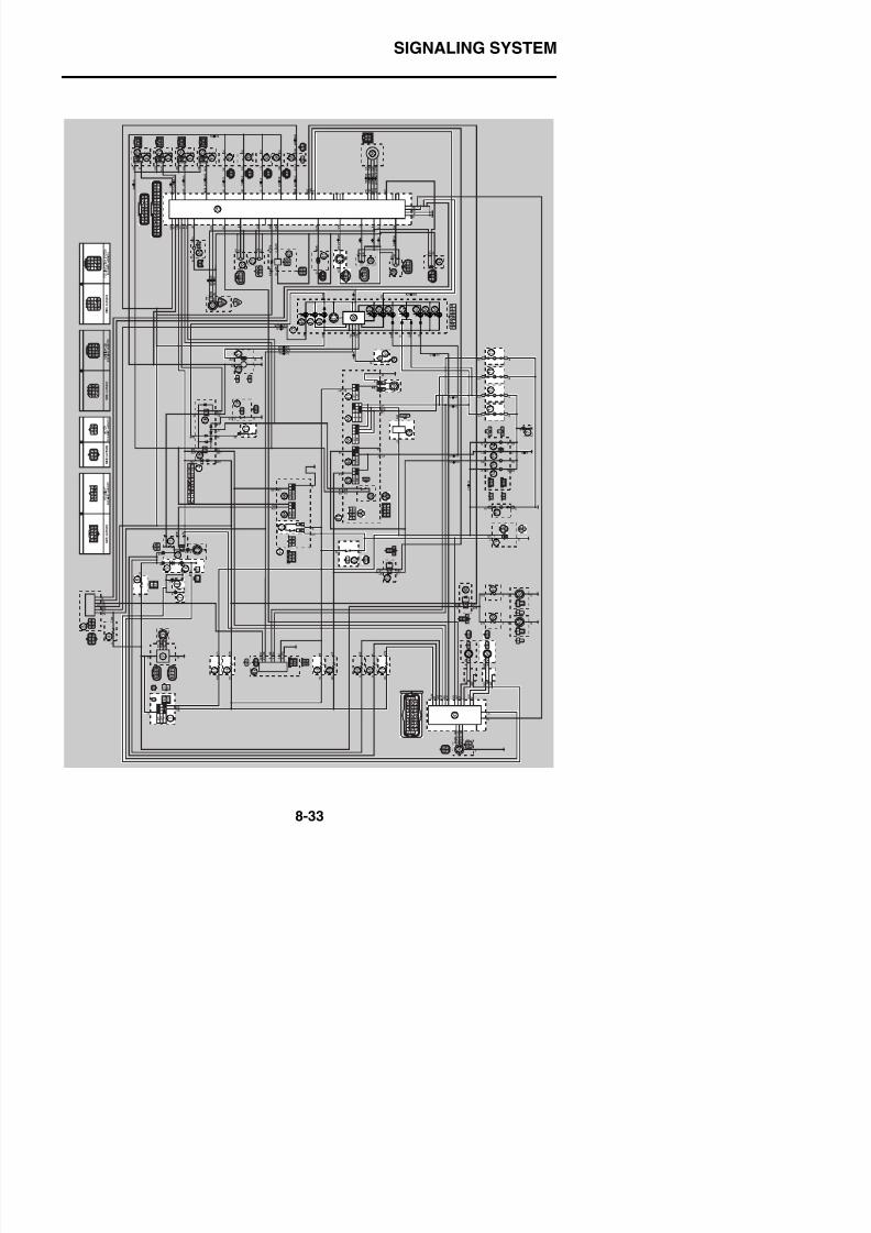
8/21/2019 Fz8 - Service Manual
http://slidepdf.com/reader/full/fz8-service-manual 428/609
SIGNALING SYSTEM
FZ8SA1. Main switch
6. Main fuse7. Frame ground
8. Engine ground
9. Battery
10.Negative battery ground lead
14.Relay unit
17.Neutral switch
20.Fuel sender
25.ECU (engine control unit)40.Coolant temperature sensor
43.Meter assembly
45.Oil level warning light
46.Neutral indicator light
47.Tachometer
48.Multi-function meter
52.Turn signal indicator light
55.Oil level switch56.Right handlebar switch
57.Front brake light switch
60.Rear brake light switch
61.Left handlebar switch
65.Hazard switch
66.Turn signal switch
67.Horn switch
68.Horn69.Turn signal/hazard relay
70.Rear right turn signal light
71.Rear left turn signal light
72.Front right turn signal light
73.Front left turn signal light
78.Tail/brake light
85.Taillight fuse
86.Ignition fuse88.Signal fuse
92.ABS ECU fuse
93.ABS ECU (electronic control unit)
96.Rear wheel sensor
SIGNALING SYSTEM

8/21/2019 Fz8 - Service Manual
http://slidepdf.com/reader/full/fz8-service-manual 429/609
SIGNALING SYSTEM
EAS27290
TROUBLESHOOTING
• Any of the following fail to light: turn signal light, brake light or an indicator light.• The horn fails to sound.
TIP
• Before troubleshooting, remove the following part(s):1. Rider seat
2. Passenger seat3. Left inner panel (FZ8SA)4. Right inner panel (FZ8SA)
5. Left side panel (FZ8SA)6. Right side panel (FZ8SA)7. Front cowling (FZ8SA)8. Fuel tank9. Air filter case10. Throttle bodies
NG→
OK↓
NG→
OK↓
NG→
OK↓
NG→
1. Check the fuses.
(Main, ignition, signal and taillight)Refer to “CHECKING THE FUSES”on page 8-185.
Replace the fuse(s).
2. Check the battery.
Refer to “CHECKING ANDCHARGING THE BATTERY” onpage 8-186.
• Clean the battery terminals.• Recharge or replace the battery.
3. Check the main switch.Refer to “CHECKING THESWITCHES” on page 8-179.
Replace the main switch/immobilizerunit.
4. Check the entire signaling system’swiring.Refer to “CIRCUIT DIAGRAM” onpage 8-31.
Properly connect or repair the signal-ing system’s wiring.
SIGNALING SYSTEM
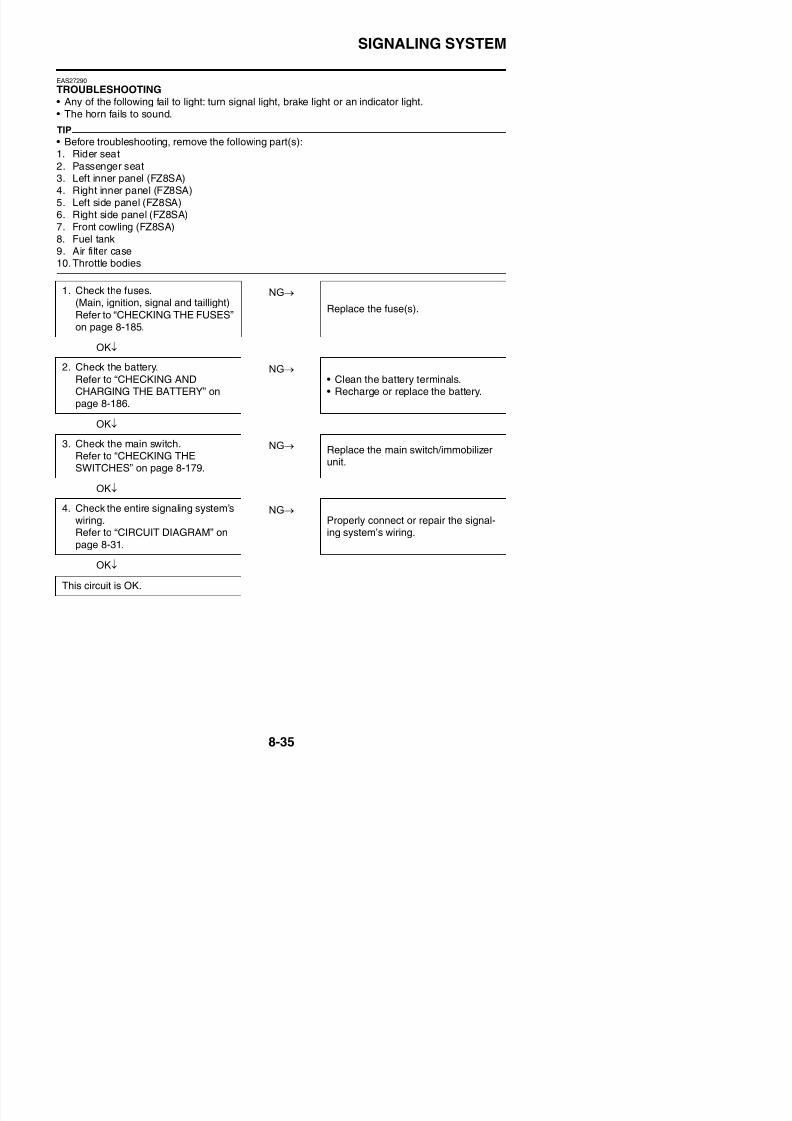
8/21/2019 Fz8 - Service Manual
http://slidepdf.com/reader/full/fz8-service-manual 430/609
SIGNALING SYSTEM
Check the signaling system
The horn fails to sound.
NG→
OK↓
NG→
OK↓
NG→
OK↓
The tail/brake light fails to come on.
NG→
OK↓
NG→
OK↓
NG→
1. Check the horn switch.Refer to “CHECKING THESWITCHES” on page 8-179.
Replace the left handlebar switch.
2. Check the horn.Refer to “CHECKING THE HORN”on page 8-196.
Replace the horn.
3. Check the entire signaling system’swiring.Refer to “CIRCUIT DIAGRAM” onpage 8-31.
Properly connect or repair the signal-ing system’s wiring.
This circuit is OK.
1. Check the tail/brake light bulb andsocket.Refer to “CHECKING THE BULBS
AND BULB SOCKETS” on page 8-184.
Replace the tail/brake light bulb,
socket or both.
2. Check the front brake light switch.
Refer to “CHECKING THESWITCHES” on page 8-179.
Replace the front brake light switch.
3. Check the rear brake light switch.
Refer to “CHECKING THESWITCHES” on page 8-179.
Replace the rear brake light switch.
SIGNALING SYSTEM
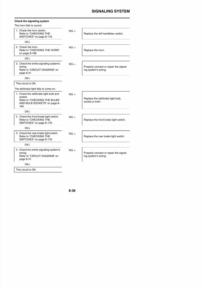
8/21/2019 Fz8 - Service Manual
http://slidepdf.com/reader/full/fz8-service-manual 431/609
SIGNALING SYSTEM
The turn signal light, turn signal indicator light or both fail to blink.
NG→
OK↓
NG→
OK↓
NG→
OK↓
NG→
OK↓
NG→
OK↓
The neutral indicator light fails to come on.
NG→
OK↓
1. Check the turn signal light bulb andsocket.Refer to “CHECKING THE BULBSAND BULB SOCKETS” on page 8-184.
Replace the turn signal light bulb(s),socket(s) or both.
2. Check the turn signal switch.
Refer to “CHECKING THESWITCHES” on page 8-179.
Replace the left handlebar switch.
3. Check the hazard switch.Refer to “CHECKING THESWITCHES” on page 8-179.
Replace the left handlebar switch.
4. Check the turn signal/hazard relay.Refer to “CHECKING THE TURNSIGNAL/HAZARD RELAY” on page8-190.
Replace the turn signal/hazard relay.
5. Check the entire signaling system’swiring.Refer to “CIRCUIT DIAGRAM” onpage 8-31.
Properly connect or repair the signal-ing system’s wiring.
This circuit is OK.
1. Check the neutral switch.Refer to “CHECKING THESWITCHES” on page 8-179.
Replace the neutral switch.
SIGNALING SYSTEM
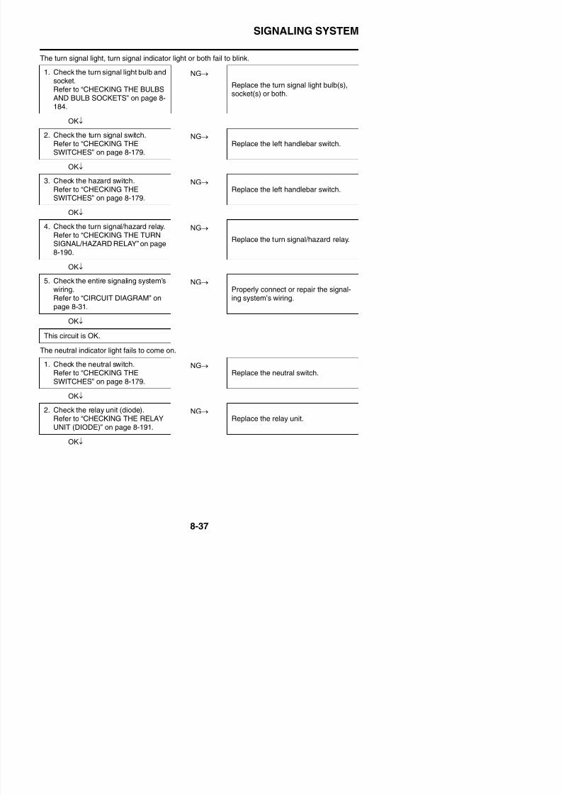
8/21/2019 Fz8 - Service Manual
http://slidepdf.com/reader/full/fz8-service-manual 432/609
NG→
OK↓
The oil level warning light fails to come on.
NG→
OK↓
NG→
OK↓
The fuel level warning light fails to come on.
NG→
OK↓
NG→
OK↓
The speedometer fails to operate.
3. Check the entire signaling system’s
wiring.Refer to “CIRCUIT DIAGRAM” onpage 8-31.
Properly connect or repair the signal-ing system’s wiring.
Replace the meter assembly.
1. Check the oil level switch.Refer to “CHECKING THESWITCHES” on page 8-179.
Replace the oil level switch.
2. Check the entire signaling system’swiring.
Refer to “CIRCUIT DIAGRAM” onpage 8-31.
Properly connect or repair the signal-
ing system’s wiring.
Replace the meter assembly.
1. Check the fuel sender.
Refer to “CHECKING THE FUELSENDER” on page 8-197.
Replace the fuel pump assembly.
2. Check the entire signaling system’s
wiring.Refer to “CIRCUIT DIAGRAM” onpage 8-31.
Properly connect or repair the signal-ing system’s wiring.
Replace the ECU or meter assembly.
SIGNALING SYSTEM
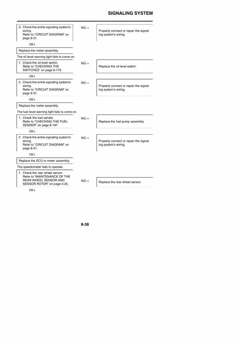
8/21/2019 Fz8 - Service Manual
http://slidepdf.com/reader/full/fz8-service-manual 433/609
NG→
OK↓
TIP
Repair or replace if there is an open or short circuit.• Between rear wheel sensor coupler and ABS ECU coupler.(White/red–White/red)(White–White)
• Between ABS ECU coupler and ECU coupler.(Blue/white–Blue/white)(White/yellow–White/yellow)
• Between ECU coupler and meter assembly.
(Yellow/blue–Yellow/blue)
The coolant temperature warning light fails to come on.
NG→
OK↓
NG→
OK↓
2. Check the entire speed sensor wir-
ing.Refer to TIP.
Properly connect or repair the speed
sensor wiring.
Replace the hydraulic unit assembly,ECU, meter assembly.
1. Check the coolant temperaturesensor.Refer to “CHECKING THE COOL-ANT TEMPERATURE SENSOR”on page 8-198.
Replace the coolant temperature sen-sor.
2. Check the entire signaling system’swiring.Refer to “CIRCUIT DIAGRAM” onpage 8-31.
Properly connect or repair the signal-ing system’s wiring.
Replace the ECU or meter assembly.
SIGNALING SYSTEM
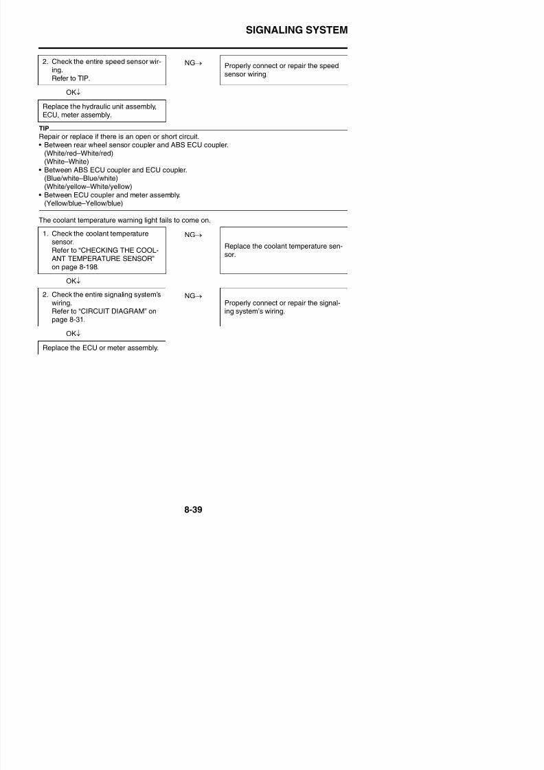
8/21/2019 Fz8 - Service Manual
http://slidepdf.com/reader/full/fz8-service-manual 434/609
COOLING SYSTEM

8/21/2019 Fz8 - Service Manual
http://slidepdf.com/reader/full/fz8-service-manual 435/609
EAS27300
COOLING SYSTEM
EAS27310
CIRCUIT DIAGRAM
COOLING SYSTEM
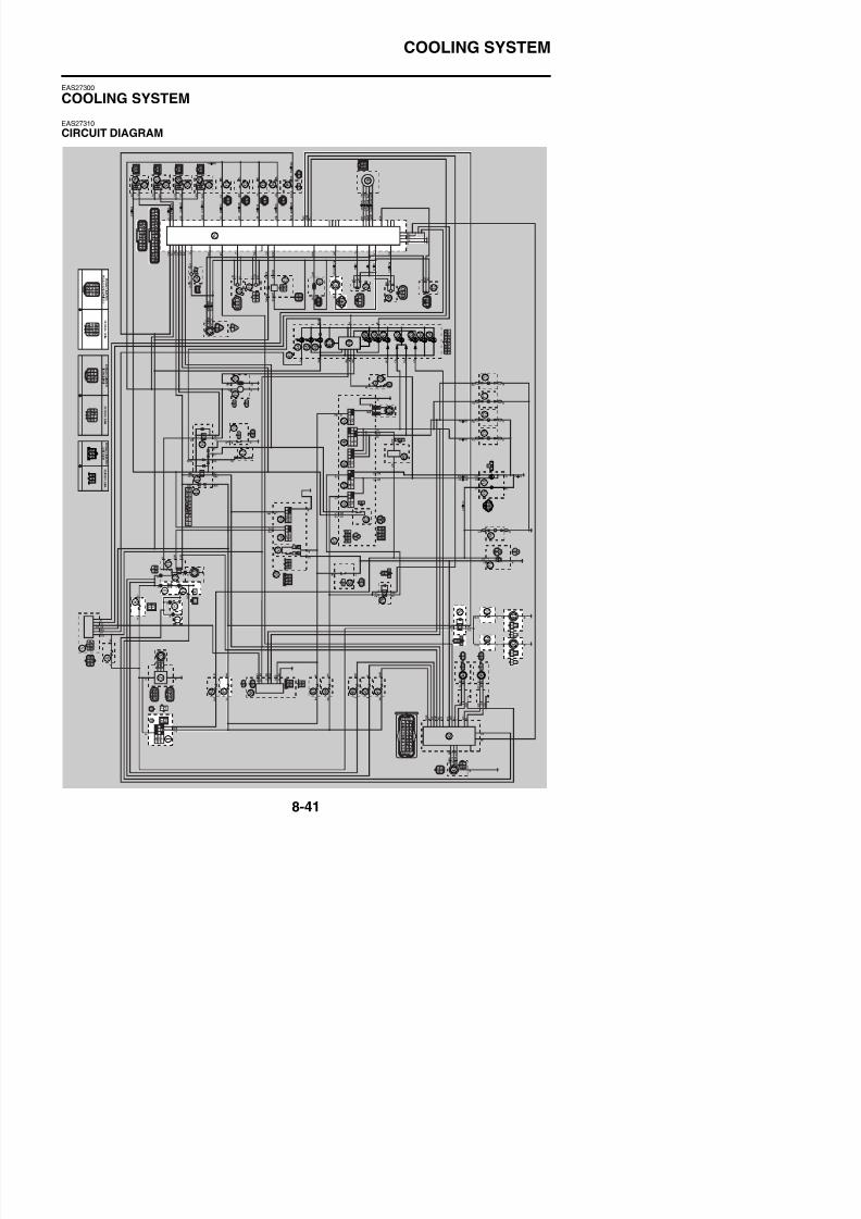
8/21/2019 Fz8 - Service Manual
http://slidepdf.com/reader/full/fz8-service-manual 436/609
FZ8NA1. Main switch
6. Main fuse7. Frame ground
8. Engine ground
9. Battery
10.Negative battery ground lead
25.ECU (engine control unit)
40.Coolant temperature sensor
79.Radiator fan motor relay
80.Right radiator fan motor fuse81.Right radiator fan motor
82.Left radiator fan motor fuse
83.Left radiator fan motor
85.Ignition fuse
COOLING SYSTEM
8/21/2019 Fz8 - Service Manual
http://slidepdf.com/reader/full/fz8-service-manual 437/609
COOLING SYSTEM
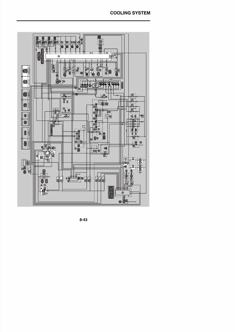
8/21/2019 Fz8 - Service Manual
http://slidepdf.com/reader/full/fz8-service-manual 438/609
FZ8SA1. Main switch
6. Main fuse7. Frame ground
8. Engine ground
9. Battery
10.Negative battery ground lead
25.ECU (engine control unit)
40.Coolant temperature sensor
80.Radiator fan motor relay
81.Right radiator fan motor fuse82.Right radiator fan motor
83.Left radiator fan motor fuse
84.Left radiator fan motor
86.Ignition fuse
COOLING SYSTEM

8/21/2019 Fz8 - Service Manual
http://slidepdf.com/reader/full/fz8-service-manual 439/609
EAS27320
TROUBLESHOOTING
TIP• Before troubleshooting, remove the following part(s):1. Rider seat2. Passenger seat3. Left inner panel (FZ8SA)
4. Right inner panel (FZ8SA)5. Left side panel (FZ8SA)6. Right side panel (FZ8SA)
7. Front cowling (FZ8SA)8. Fuel tank9. Air filter case10. Throttle bodies
NG→
OK↓
NG→
OK↓
NG→
OK↓
NG→
OK↓
1. Check the fuses.(Main, ignition and radiator fanmotor)
Refer to “CHECKING THE FUSES”on page 8-185.
Replace the fuse(s).
2. Check the battery.Refer to “CHECKING AND
CHARGING THE BATTERY” onpage 8-186.
• Clean the battery terminals.
• Recharge or replace the battery.
3. Check the main switch.
Refer to “CHECKING THESWITCHES” on page 8-179.
Replace the main switch/immobilizerunit.
4. Check the radiator fan motor.Refer to “CHECKING THE RADIA-TOR FAN MOTORS” on page 8-198.
Replace the radiator fan motor(s).
COOLING SYSTEM
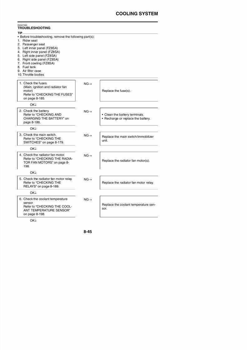
8/21/2019 Fz8 - Service Manual
http://slidepdf.com/reader/full/fz8-service-manual 440/609
NG→
OK↓
7. Check the entire cooling system’swiring.Refer to “CIRCUIT DIAGRAM” onpage 8-41.
Properly connect or repair the coolingsystem’s wiring.
Replace the ECU.
FUEL INJECTION SYSTEM
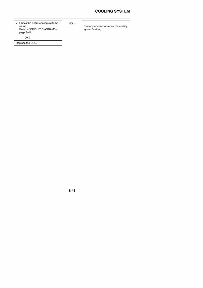
8/21/2019 Fz8 - Service Manual
http://slidepdf.com/reader/full/fz8-service-manual 441/609
EAS27331
FUEL INJECTION SYSTEM
EAS27340
CIRCUIT DIAGRAM
FUEL INJECTION SYSTEM
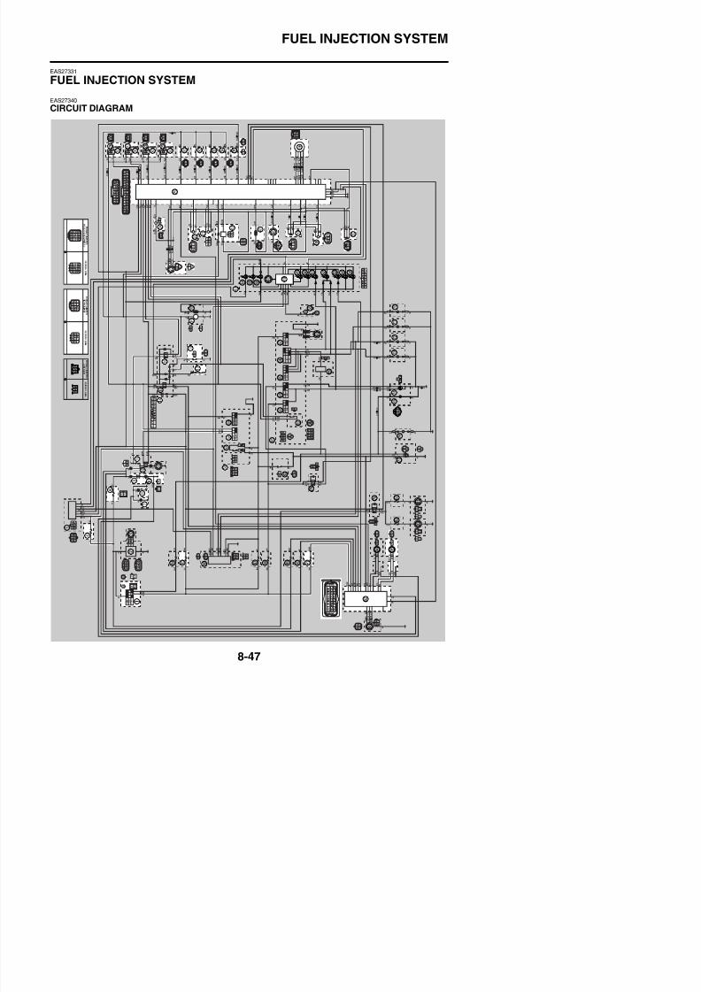
8/21/2019 Fz8 - Service Manual
http://slidepdf.com/reader/full/fz8-service-manual 442/609
FZ8NA1. Main switch
4. Backup fuse6. Main fuse
7. Frame ground
8. Engine ground
9. Battery
10.Negative battery ground lead
11.Fuel injection system fuse
14.Relay unit
16.Fuel pump relay17.Neutral switch
18.Sidestand switch
19.Fuel pump
21.Lean angle sensor
22.Atmospheric pressure sensor
23.Cylinder identification sensor
24.Crankshaft position sensor
25.ECU (engine control unit)
26.Ignition coil #1
27.Ignition coil #2
28.Ignition coil #3
29.Ignition coil #4
30.Spark plug
31.Injector #1
32.Injector #2
33.Injector #3
34.Injector #4
35.Air induction system solenoid
36.Sub-throttle servo motor
37.Sub-throttle position sensor
38.Intake air pressure sensor
39.Throttle position sensor
40.Coolant temperature sensor
41.Intake air temperature sensor
42.O2 sensor
43.Meter assembly
48.Multi-function meter
49.Engine trouble warning light
56 Right handlebar switch
FUEL INJECTION SYSTEM

8/21/2019 Fz8 - Service Manual
http://slidepdf.com/reader/full/fz8-service-manual 443/609
FUEL INJECTION SYSTEM
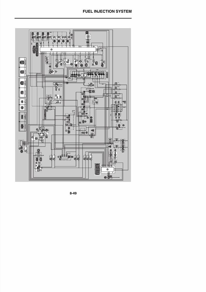
8/21/2019 Fz8 - Service Manual
http://slidepdf.com/reader/full/fz8-service-manual 444/609
FZ8SA1. Main switch
4. Backup fuse6. Main fuse
7. Frame ground
8. Engine ground
9. Battery
10.Negative battery ground lead
11.Fuel injection system fuse
14.Relay unit
16.Fuel pump relay17.Neutral switch
18.Sidestand switch
19.Fuel pump
21.Lean angle sensor
22.Atmospheric pressure sensor
23.Cylinder identification sensor
24.Crankshaft position sensor
25.ECU (engine control unit)
26.Ignition coil #1
27.Ignition coil #2
28.Ignition coil #3
29.Ignition coil #4
30.Spark plug
31.Injector #1
32.Injector #2
33.Injector #3
34.Injector #4
35.Air induction system solenoid
36.Sub-throttle servo motor
37.Sub-throttle position sensor
38.Intake air pressure sensor
39.Throttle position sensor
40.Coolant temperature sensor
41.Intake air temperature sensor
42.O2 sensor
43.Meter assembly
48.Multi-function meter
49.Engine trouble warning light
56 Right handlebar switch
FUEL INJECTION SYSTEM
8/21/2019 Fz8 - Service Manual
http://slidepdf.com/reader/full/fz8-service-manual 445/609
EAS27351
ECU SELF-DIAGNOSTIC FUNCTIONThe ECU is equipped with a self-diagnostic function in order to ensure that the fuel injection systemis operating normally. If this function detects a malfunction in the system, it immediately operates theengine under substitute characteristics and illuminates the engine trouble warning light to alert therider that a malfunction has occurred in the system. Once a malfunction has been detected, a faultcode number is stored in the memory of the ECU.• To inform the rider that the fuel injection system is not functioning, the engine trouble warning light
flashes while the start switch is being pushed to start the engine.• If a malfunction is detected in the system by the self-diagnostic function, the ECU provides an
appropriate substitute characteristic operation, and alerts the rider of the detected malfunction byilluminating the engine trouble warning light.
• After the engine has been stopped, the lowest fault code number appears on the clock/odometer/ tripmeter/fuel reserve tripmeter LCD. Once a fault code has been displayed, it remains stored inthe memory of the ECU until it is deleted.
Engine trouble warning light indication and fuel injection system operation
* The warning light flashes when any one of the following conditions is present and the start switchis pushed:
Checking the engine trouble warning light
Warning light indica-tion
ECU operationFuel injection opera-tion
Vehicle operation
Flashing*Warning providedwhen unable to startengine
Operation stopped Cannot be operated
Remains on Malfunction detected
Operated with substi-tute characteristics inaccordance with thedescription of the mal-
function
Can or cannot be oper-ated depending on thefault code
11: Cylinder identification sensor 30:Lean angle sensor
(latch up detected)
12: Crankshaft position sensor 41:Lean angle sensor
(open or short circuit)
19:Sidestand switch(open circuit in the wire to the ECU)
50:ECU internal malfunction(faulty ECU memory)
FUEL INJECTION SYSTEM
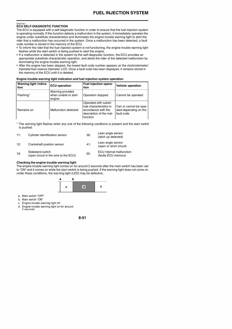
8/21/2019 Fz8 - Service Manual
http://slidepdf.com/reader/full/fz8-service-manual 446/609
ECU detects an abnormal signal from a sensorIf the ECU detects an abnormal signal from a sensor while the vehicle is being driven, the ECU illu-
minates the engine trouble warning light and provides the engine with alternate operating instruc-tions that are appropriate for the type of malfunction.When an abnormal signal is received from a sensor, the ECU processes the specified values thatare programmed for each sensor in order to provide the engine with alternate operating instructionsthat enable the engine to continue operating or stop operating, depending on the conditions.
FUEL INJECTION SYSTEM
8/21/2019 Fz8 - Service Manual
http://slidepdf.com/reader/full/fz8-service-manual 447/609
EAS30580
TROUBLESHOOTING METHOD
The engine operation is not normal and theengine trouble warning light comes on.1. Check:
• Fault code number
a. Check the fault code number displayed onthe meter.
b. Identify the faulty system with the fault code
number.c. Identify the probable cause of the malfunc-
tion.
2. Check and repair the probable cause of themalfunction.
3. Perform the reinstatement action for thefuel injection system.Refer to “Reinstatement method” in the
appropriate table in “TROUBLESHOOTINGDETAILS” on page 8-55.
4. Set the main switch to “OFF”, then to “ON”again, and then check that no fault codenumber is displayed.
The engine operation is not normal, but theengine trouble warning light does not come
on.1. Check the operation of the following sen-sors and actuators in the diagnostic mode.Refer to “TROUBLESHOOTING DETAILS”on page 8-55.
If a malfunction is detected in the sensors
or actuators, repair or replace all faultyparts.If no malfunction is detected in the sensorsand actuators, check and repair the innerparts of the engine.
Fault code No. No fault code No.
Check and repair.Refer to “TROUBLE-SHOOTINGDETAILS” on page 8-55.Monitor the operationof the sensors andactuators in the diag-
nostic mode. Refer to“TROUBLESHOOT-ING DETAILS” onpage 8-55.
Check and repair.
d:01: Throttle position sensor (throttle angle)d:02: Atmospheric pressure sensord:03: Intake air pressure sensor
d:05: Intake air temperature sensord:06: Coolant temperature sensord:07: Speed sensord:08: Lean angle sensord:30: Cylinder-#1 ignition coild:31: Cylinder-#2 ignition coild:32: Cylinder-#3 ignition coild:33: Cylinder-#4 ignition coil
d:36: Injector #1d:37: Injector #2d:38: Injector #3d:39: Injector #4d:48: Air induction system solenoidd:56: Sub-throttle servo motor
FUEL INJECTION SYSTEM
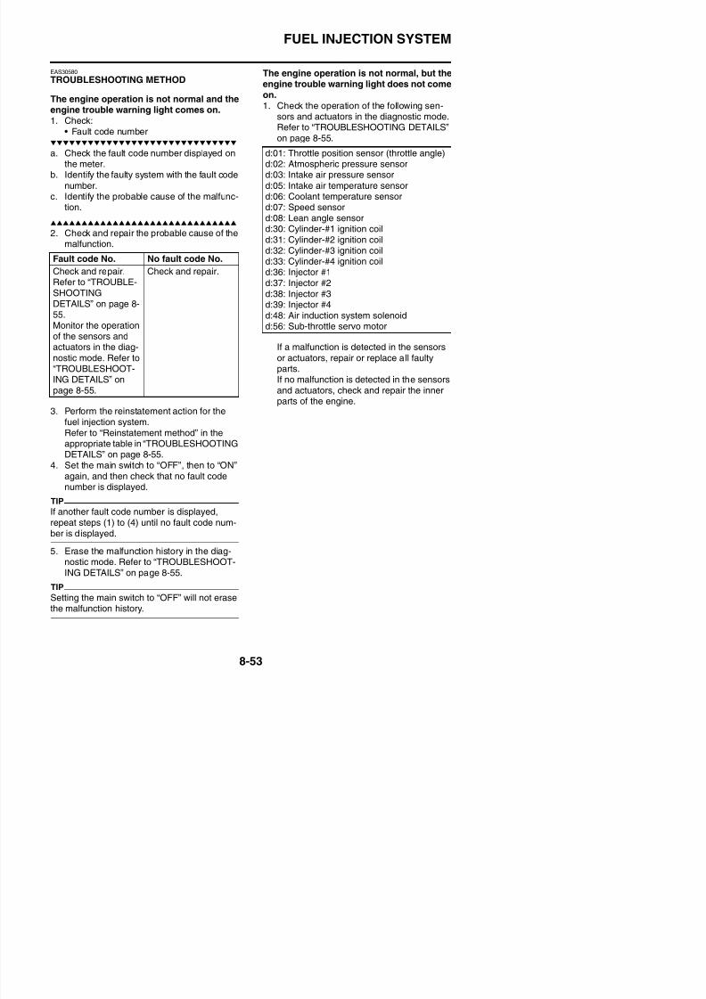
8/21/2019 Fz8 - Service Manual
http://slidepdf.com/reader/full/fz8-service-manual 448/609
EAS27411
DIAGNOSTIC MODESetting the diagnostic mode
1. Turn the main switch to “OFF” and set the engine stop switch to “ON”.2. Disconnect the wire harness coupler from the fuel pump.3. Simultaneously press and hold the “SELECT” and “RESET” buttons, turn the main switch to
“ON”, and continue to press the buttons for 8 seconds or more.
TIP
• All displays on the meter disappear except the odometer/tripmeter/fuel reserve tripmeter displays.• “dI” appears on the odometer/tripmeter/fuel reserve tripmeter LCD.
4. Press the “SELECT” button to select the diagnostic mode “dI”.5. After selecting “dI”, simultaneously press the “SELECT” and “RESET” buttons for 2 seconds or
more to activate the diagnostic mode. The diagnostic code number “d01” appears on the clockLCD.
6. Set the engine stop switch to “ ”.
7. Select the diagnostic code number corresponding to the fault code number by pressing the
“SELECT” and “RESET” buttons.TIP
The diagnostic code number appears on the clock LCD (d01–d70).• To decrease the selected diagnostic code number, press the “RESET” button. Press the “RESET”
button for 1 second or longer to automatically decrease the diagnostic code numbers.
• To increase the selected diagnostic code number, press the “SELECT” button. Press the“SELECT” button for 1 second or longer to automatically increase the diagnostic code numbers.
FUEL INJECTION SYSTEM
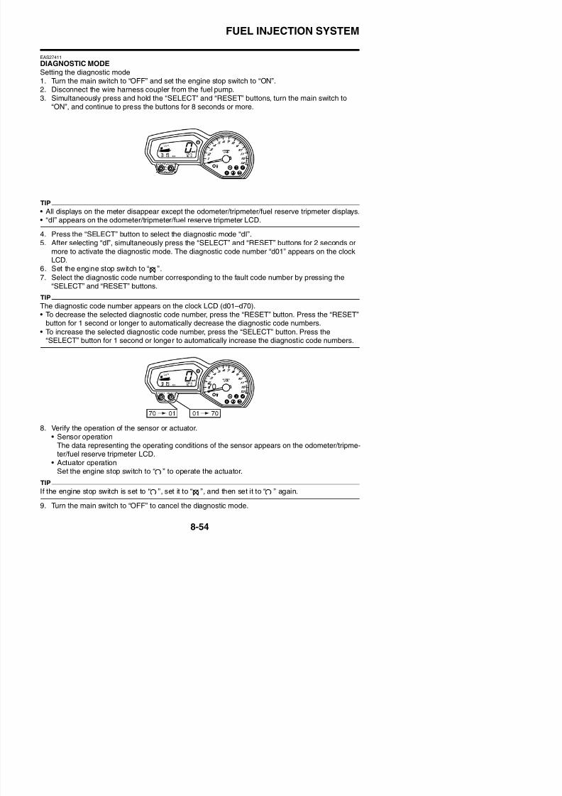
8/21/2019 Fz8 - Service Manual
http://slidepdf.com/reader/full/fz8-service-manual 449/609
EAS27462
TROUBLESHOOTING DETAILSThis section describes the measures per fault code number displayed on the meter. Check and ser-
vice the items or components that are the probable cause of the malfunction following the ordergiven.After the check and service of the malfunctioning part have been completed, reset the meter displayaccording to the reinstatement method.Fault code No.:
Fault code number displayed on the meter when the engine failed to work normally.Diagnostic code No.:Diagnostic code number to be used when the diagnostic mode is operated. Refer to “DIAGNOSTIC
MODE” on page 8-54.
Fault code No. 11
ItemCylinder identification sensor: no normal signals are received fromthe cylinder identification sensor.
Fail-safe systemUnable to start engine
Able to drive vehicle
Diagnostic code No. —
Meter display —
Procedure —
Item/components andprobable cause
Check or maintenance jobSensor inspection proce-
dure
1 Connection of cylinder identi-fication sensor couplerCheck the connection of the
coupler is secure.Remove the coupler, andcheck each pin (for bending,wear, or locking).
Poor connection → Connect itsecurely, or repair/replace thewire harness.
Crank the engine, and checkthe fault code indication.No fault code indicated. →
Recovered.Fault code indicated. → Check the next step.
2 Connection of wire harnessECU couplerCheck the connection of thecoupler is secure.
Remove the coupler, andcheck each pin (for bending,wear, or locking).
Poor connection → Connect itsecurely, or repair/replace thewire harness.
Crank the engine, and checkthe fault code indication.No fault code indicated. → Recovered.
Fault code indicated. → Check the next step.
3 Connection of ignition systemsub-wire harness coupler
Poor connection → Connect itsecurely, or repair/replace the
Crank the engine, and checkthe fault code indication.
FUEL INJECTION SYSTEM
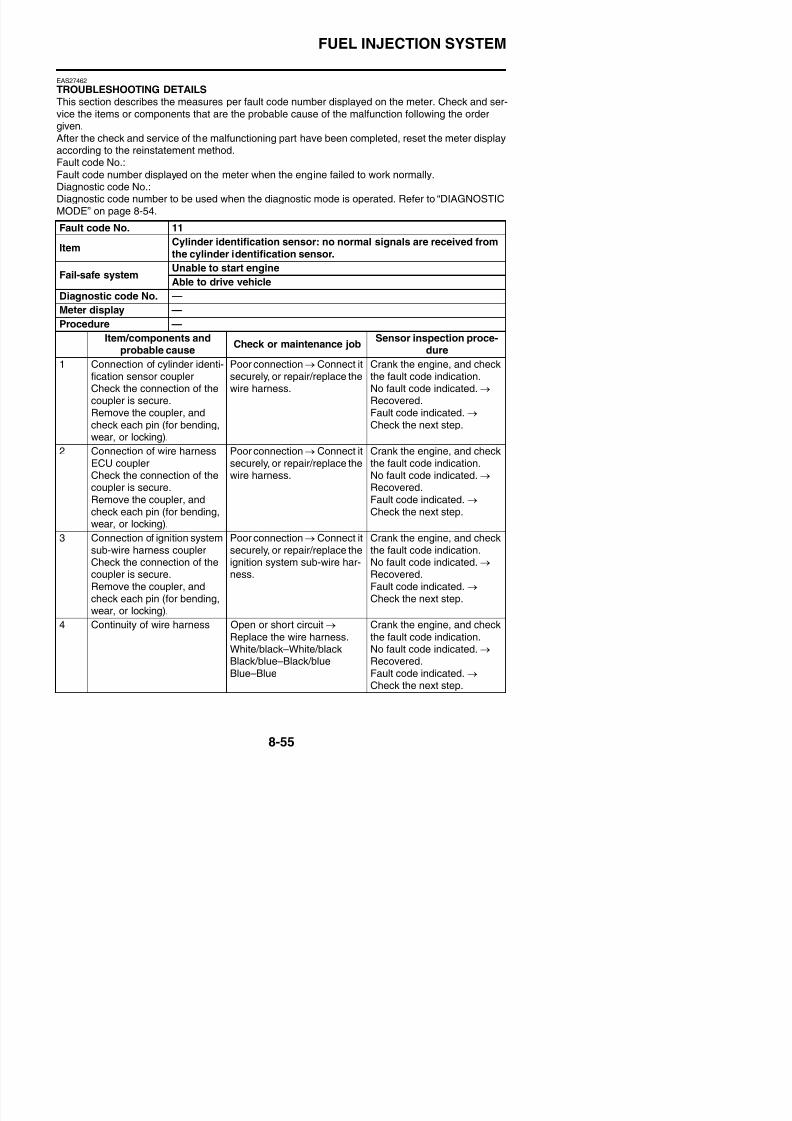
8/21/2019 Fz8 - Service Manual
http://slidepdf.com/reader/full/fz8-service-manual 450/609
5 Sensor installation status- Check the mounting sec-
tion for loose or pinchedmounting.
Incorrect installation → Rein-stall or repair the sensor.
Crank the engine, and checkthe fault code indication.No fault code indicated. → Recovered.Fault code indicated. → Check the next step.
6 Cylinder identification sensor
malfunction
Sensor inspection procedure
Refer to “CHECKING THECYLINDER IDENTIFICA-TION SENSOR” on page 8-201.Replace if defective.
Crank the engine, and check
the fault code indication.No fault code indicated. → Recovered.Fault code indicated. → Check the next step.
7 ECU malfunction Replace the ECU.
Fault code No. 12Item
Crankshaft position sensor: no normal signals are received from thecrankshaft position sensor.
Fail-safe systemUnable to start engine
Unable to drive vehicle
Diagnostic code No. —
Meter display —
Procedure —
Item/components andprobable cause
Check or maintenance jobSensor inspection proce-
dure
1 Connection of crankshaftposition sensor couplerCh k th ti f th
Poor connection → Connect itsecurely, or repair/replace the
i h
Crank the engine, and checkthe fault code indication.N f lt d i di t d
Fault code No. 11
Item
Cylinder identification sensor: no normal signals are received from
the cylinder identification sensor.
Fail-safe systemUnable to start engine
Able to drive vehicle
Diagnostic code No. —
Meter display —
Procedure —
Item/components and
probable causeCheck or maintenance job
Sensor inspection proce-
dure
FUEL INJECTION SYSTEM
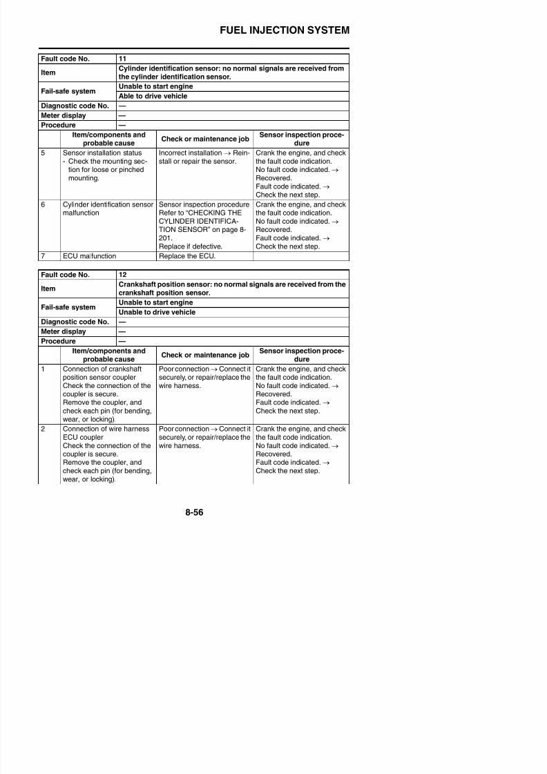
8/21/2019 Fz8 - Service Manual
http://slidepdf.com/reader/full/fz8-service-manual 451/609
3 Continuity of wire harness Open or short circuit → Replace the wire harness.Gray–GrayBlack/blue–Black/blue
Crank the engine, and checkthe fault code indication.No fault code indicated. → Recovered.Fault code indicated. → Check the next step.
4 Sensor installation status
- Check the mounting sec-tion for loose or pinchedmounting.
- Check the sensor andpickup rotor clearance (0.5mm (0.02 in)).
Incorrect installation → Rein-
stall or repair the sensor.
Crank the engine, and check
the fault code indication.No fault code indicated. → Recovered.Fault code indicated. → Check the next step.
5 Crankshaft position sensormalfunction
Sensor inspection procedureRefer to “CHECKING THE
CRANKSHAFT POSITIONSENSOR” on page 8-193.Replace if defective.
Crank the engine, and checkthe fault code indication.
No fault code indicated. → Recovered.Fault code indicated. →
Check the next step.
6 ECU malfunction Replace the ECU.
Fault code No. 13
Item Intake air pressure sensor: open or short circuit detected. (no nor-mal signals are received from the intake air pressure sensor.)
Fail-safe systemAble to start engine
Able to drive vehicle
Diagnostic code No. d:03
Fault code No. 12
Item
Crankshaft position sensor: no normal signals are received from the
crankshaft position sensor.
Fail-safe systemUnable to start engine
Unable to drive vehicle
Diagnostic code No. —
Meter display —
Procedure —
Item/components and
probable causeCheck or maintenance job
Sensor inspection proce-
dure
FUEL INJECTION SYSTEM
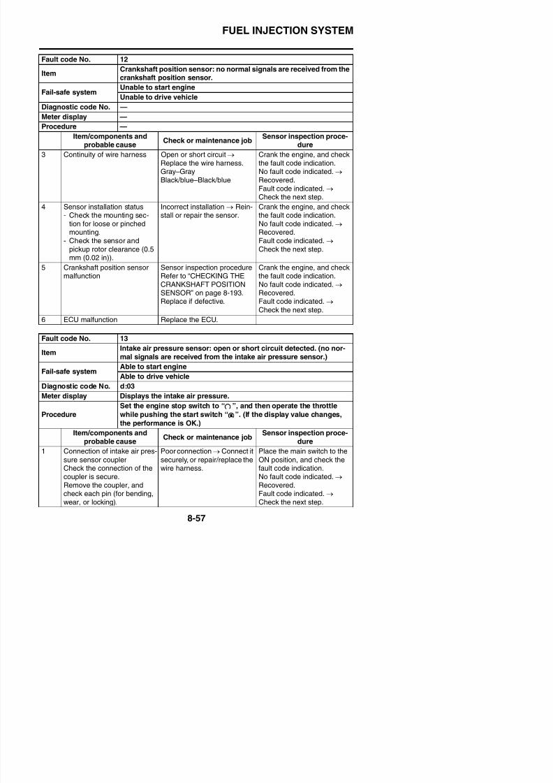
8/21/2019 Fz8 - Service Manual
http://slidepdf.com/reader/full/fz8-service-manual 452/609
2 Connection of wire harnessECU couplerCheck the connection of thecoupler is secure.Remove the coupler and
check each pin (for bending,wear, or locking).
Poor connection → Connect itsecurely, or repair/replace thewire harness.
Place the main switch to theON position, and check thefault code indication.No fault code indicated. → Recovered.
Fault code indicated. → Check the next step.
3 Connection of fuel injectionsystem sub-wire harnesscouplerCheck the connection of thecoupler is secure.Remove the coupler and
check each pin (for bending,wear, or locking).
Poor connection → Connect itsecurely, or repair/replace thewire harness.
Place the main switch to theON position, and check thefault code indication.No fault code indicated. → Recovered.Fault code indicated. →
Check the next step.
4 Continuity of wire harness Open or short circuit → Replace the wire harness.Black/blue–Black/bluePink/white–Pink/whiteBlue–Blue
Place the main switch to theON position, and check thefault code indication.No fault code indicated. → Recovered.Fault code indicated. →
Check the next step.
5 Sensor installation status- Check the mounting sec-
tion for loose or pinchedmounting
Incorrect installation → Rein-stall or repair the sensor.
Place the main switch to theON position, and check thefault code indication.No fault code indicated →
Fault code No. 13
ItemIntake air pressure sensor: open or short circuit detected. (no nor-
mal signals are received from the intake air pressure sensor.)
Fail-safe systemAble to start engine
Able to drive vehicle
Diagnostic code No. d:03
Meter display Displays the intake air pressure.
Procedure
Set the engine stop switch to “ ”, and then operate the throttle
while pushing the start switch “ ”. (If the display value changes,
the performance is OK.)Item/components and
probable causeCheck or maintenance job
Sensor inspection proce-dure
FUEL INJECTION SYSTEM

8/21/2019 Fz8 - Service Manual
http://slidepdf.com/reader/full/fz8-service-manual 453/609
6 Intake air pressure sensormalfunction
Check in the diagnostic mode(Code No. d03).When engine is stopped:Atmospheric pressure at thecurrent altitude and weather
conditions is indicated.0 m above sea level: Approx.101 kPa1000 m above sea level:Approx. 90 kPa2000 m above sea level:Approx. 80 kPa3000 m above sea level:
Approx. 70 kPaWhen engine is cranking:Make sure that the indicationvalue changes.Incorrect indication → Sensor
malfunction → Replace theintake air pressure sensor.Sensor inspection procedure
Refer to “CHECKING THEINTAKE AIR PRESSURESENSOR” on page 8-201.
Place the main switch to theON position, and check thefault code indication.No fault code indicated. → Recovered.
Fault code indicated. → Check the next step.
7 ECU malfunction Replace the ECU.
Fault code No. 13
ItemIntake air pressure sensor: open or short circuit detected. (no nor-
mal signals are received from the intake air pressure sensor.)
Fail-safe systemAble to start engine
Able to drive vehicle
Diagnostic code No. d:03
Meter display Displays the intake air pressure.
Procedure
Set the engine stop switch to “ ”, and then operate the throttle
while pushing the start switch “ ”. (If the display value changes,
the performance is OK.)Item/components and
probable causeCheck or maintenance job
Sensor inspection proce-dure
FUEL INJECTION SYSTEM
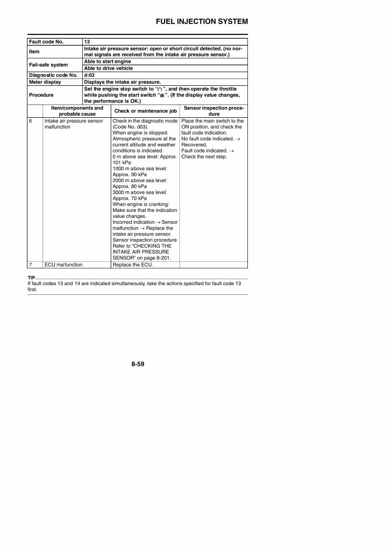
8/21/2019 Fz8 - Service Manual
http://slidepdf.com/reader/full/fz8-service-manual 454/609
Fault code No. 14
Item
Intake air pressure sensor: hose system malfunction (clogged or
detached hose).
Fail-safe systemAble to start engine
Able to drive vehicle
Diagnostic code No. d:03
Meter display Displays the intake air pressure.
Procedure
Set the engine stop switch to “ ”, and then operate the throttle
while pushing the start switch “ ”. (If the display value changes,
the performance is OK.)Item/components and
probable causeCheck or maintenance job
Sensor inspection proce-dure
1 The intake air pressure sen-
sor hose is damaged, discon-nected, clogged, twisted orbent.
Repair or replace the sensor
hose.
Start and idle the engine for
approximately 5 seconds.Then, check the fault codeindication.No fault code indicated. →
Recovered.Fault code indicated. → Check the next step.
2 Intake air pressure sensormalfunction
Check in the diagnostic mode(Code No. d03).When engine is stopped:Atmospheric pressure at thecurrent altitude and weather
conditions is indicated.0 m above sea level: Approx.101 kPa1000 m above sea level:Approx. 90 kPa2000 m above sea level:Approx. 80 kPa3000 m above sea level:
Approx. 70 kPaWhen engine is cranking:
Make sure that the indicationvalue changes.The value does not change
FUEL INJECTION SYSTEM
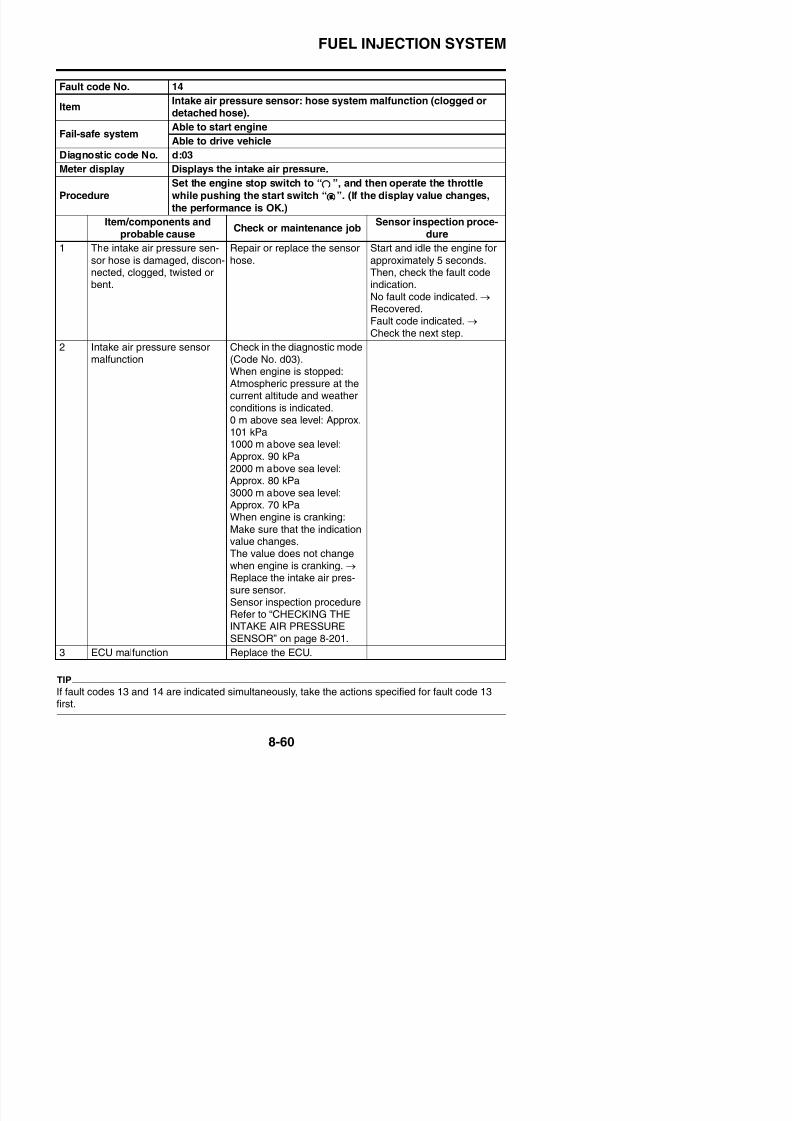
8/21/2019 Fz8 - Service Manual
http://slidepdf.com/reader/full/fz8-service-manual 455/609
Fault code No. 15
Item
Throttle position sensor: open or short circuit detected. (no normal
signals are received from the throttle position sensor.)
Fail-safe systemAble to start engine
Able to drive vehicle
Diagnostic code No. d:01
Meter displayThrottle position sensor• 14–20 (fully closed position)
Procedure• Check with throttle valves fully closed.
• Check with throttle valves fully open.Item/components and
probable causeCheck or maintenance job
Sensor inspection proce-dure
1 Connection of throttle posi-tion sensor couplerCheck the connection of thecoupler is secure.Remove the coupler, and
check each pin (for bending,wear, or locking).
Poor connection → Connect itsecurely, or repair/replace thewire harness.
Place the main switch to theON position, and check thefault code indication.No fault code indicated. → Recovered.
Fault code indicated. → Check the next step.
2 Connection of wire harnessECU couplerCheck the connection of thecoupler is secure.Remove the coupler, andcheck each pin (for bending,
wear, or locking).
Poor connection → Connect itsecurely, or repair/replace thewire harness.
Place the main switch to theON position, and check thefault code indication.No fault code indicated. → Recovered.Fault code indicated. →
Check the next step.
3 Connection of fuel injectionsystem sub-wire harnesscouplerCheck the connection of thecoupler is secure.Remove the coupler andcheck each pin (for bending,wear, or locking).
Poor connection → Connect itsecurely, or repair/replace thewire harness.
Place the main switch to theON position, and check thefault code indication.No fault code indicated. → Recovered.Fault code indicated. → Check the next step.
4 Continuity of wire harness Open or short circuit → Replace the wire harness.Black/blue–Black/blueYellow Yellow
Place the main switch to theON position, and check thefault code indication.No fault code indicated →
FUEL INJECTION SYSTEM
F lt d N 15
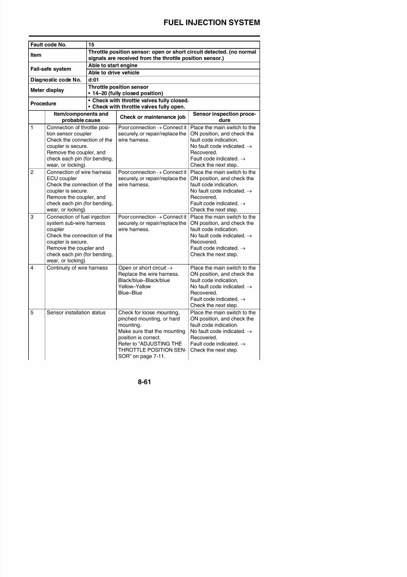
8/21/2019 Fz8 - Service Manual
http://slidepdf.com/reader/full/fz8-service-manual 456/609
6 Supply voltage of throttleposition sensor lead
Check the supply voltage.Black/blue–YellowRefer to “CHECKING THETHROTTLE POSITION SEN-SOR” on page 8-199.
Place the main switch to theON position, and check thefault code indication.No fault code indicated. → Recovered.
Fault code indicated. → Check the next step.
Line discon-nection points
Output volt-age
Disconnec-tion of groundlead
5 V
Disconnec-tion of outputline
0 V
Disconnec-tion of powersupply line
0 V
7 Throttle position sensor mal-function
Check the diagnostic mode(Code No. d01).When throttle is fully closed:A value of 14–20 is indicated.
If the indication is outside ofrange: Replace the throttleposition sensor.
Place the main switch to theON position, and check thefault code indication.No fault code indicated. →
Recovered.Fault code indicated. → Check the next step.
8 ECU malfunction Replace the ECU.
Fault code No. 15
ItemThrottle position sensor: open or short circuit detected. (no normal
signals are received from the throttle position sensor.)
Fail-safe systemAble to start engine
Able to drive vehicle
Diagnostic code No. d:01
Meter displayThrottle position sensor• 14–20 (fully closed position)
Procedure• Check with throttle valves fully closed.
• Check with throttle valves fully open.Item/components and
probable causeCheck or maintenance job
Sensor inspection proce-dure
FUEL INJECTION SYSTEM
F lt d N 16
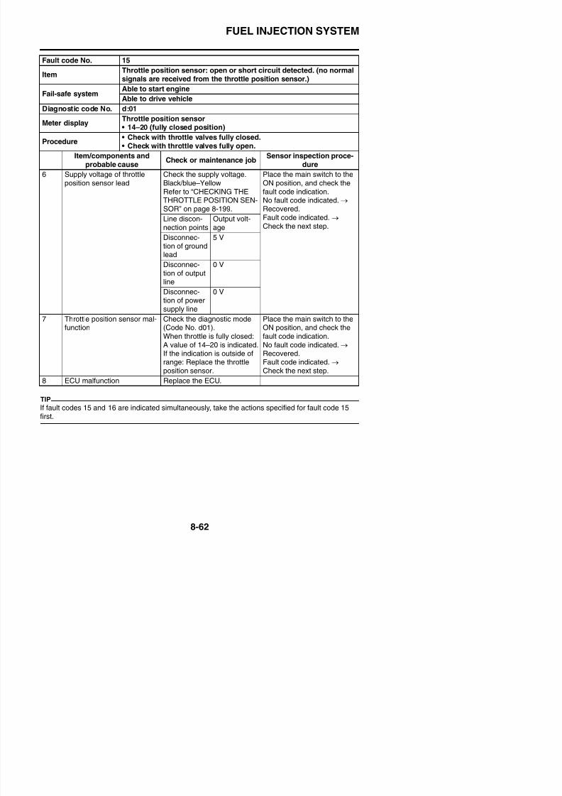
8/21/2019 Fz8 - Service Manual
http://slidepdf.com/reader/full/fz8-service-manual 457/609
TIP
If fault codes 15 and 16 are indicated simultaneously, take the actions specified for fault code 15first.
Fault code No. 16
Item
Throttle position sensor: stuck throttle position sensor detected.
(signal from throttle position sensor will not change.)
Fail-safe systemAble to start engine
Able to drive vehicle
Diagnostic code No. d:01
Meter displayThrottle position sensor• 14–20 (fully closed position)
Procedure• Check with throttle valves fully closed.
• Check with throttle valves fully open.Item/components and
probable causeCheck or maintenance job
Sensor inspection proce-dure
1 Sensor installation status Check for loose mounting,pinched mounting, or hardmounting.Make sure that the mountingposition is correct.
Refer to “ADJUSTING THETHROTTLE POSITION SEN-SOR” on page 7-11.
Place the main switch to theON position, and then openand close the throttle.No fault code indicated. → Recovered.
Fault code indicated. → Check the next step.
2 Throttle position sensor mal-function
Check in the diagnostic mode(Code No. d01).When throttle is fully closed:A value of 14–20 is indicated.If the indication is outside of
range: Replace the throttleposition sensor.
Place the main switch to theON position, and then openand close the throttle.No fault code indicated. → Recovered.
Fault code indicated. → Check the next step.
3 ECU malfunction Replace the ECU.
FUEL INJECTION SYSTEM
Fault code No 19
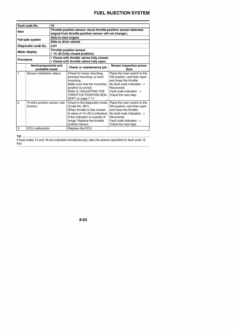
8/21/2019 Fz8 - Service Manual
http://slidepdf.com/reader/full/fz8-service-manual 458/609
Fault code No. 19
Item
Sidestand switch: a break or disconnection of the blue/yellow lead
of the ECU is detected. (no normal signals are received from the sid-estand switch.)
Fail-safe systemUnable to start engine
Unable to drive vehicle
Diagnostic code No. d:20
Meter displaySidestand switch• ON (sidestand retracted)
• OFF (sidestand extended)Procedure Extend and retract the sidestand (with the transmission in gear).
Item/components andprobable cause
Check or maintenance jobSensor inspection proce-
dure
1 Connection of sidestandswitch couplerCheck the connection of thecoupler is secure.
Remove the coupler, andcheck each pin (for bending,wear, or locking).
Poor connection → Connect itsecurely, or repair/replace thewire harness.
Place the main switch to theON position, and check thefault code indication whenthe sidestand is retracted and
extended.No fault code indicated. → Recovered.Fault code indicated. → Check the next step.
2 Connection of wire harnessECU couplerCheck the connection of the
coupler is secure.Remove the coupler, andcheck each pin (for bending,
wear, or locking).
Poor connection → Connect itsecurely, or repair/replace thewire harness.
Place the main switch to theON position, and check thefault code indication when
the sidestand is retracted andextended.No fault code indicated. →
Recovered.Fault code indicated. → Check the next step.
3 Connection of main switchcoupler
Check the connection of thecoupler is secure.Remove the coupler, andcheck each pin (for bending,wear or locking)
Poor connection → Connect itsecurely, or repair/replace the
wire harness.
Place the main switch to theON position, and check the
fault code indication whenthe sidestand is retracted andextended.No fault code indicated. → Recovered
FUEL INJECTION SYSTEM
Fault code No. 19
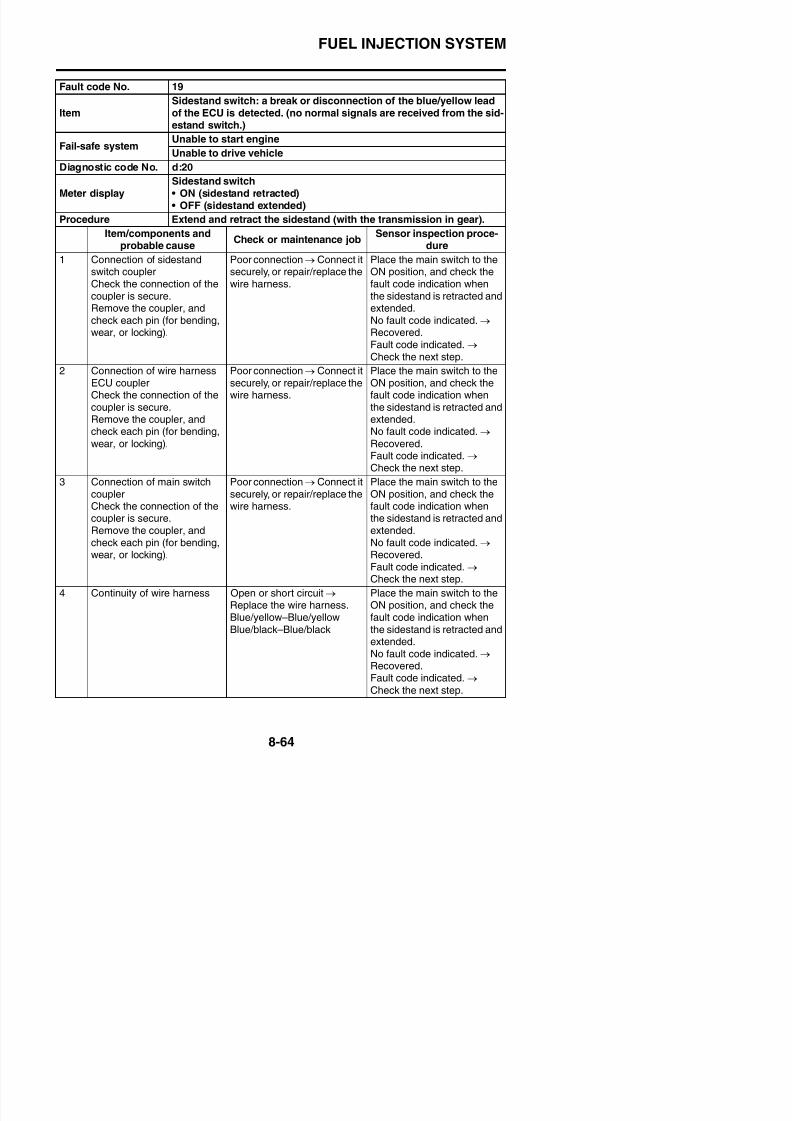
8/21/2019 Fz8 - Service Manual
http://slidepdf.com/reader/full/fz8-service-manual 459/609
5 Sidestand switch malfunction Diagnostic mode (Code No.d20).The transmission is in gearSidestand retracted: ON indi-
cationSidestand extended: OFFindicationIndication is incorrect. → Replace the sidestand switch.
Place the main switch to theON position, and check thefault code indication whenthe sidestand is retracted and
extended.No fault code indicated. → Recovered.Fault code indicated. → Check the next step.
6 ECU malfunction Replace the ECU.
Fault code No. 19
Item
Sidestand switch: a break or disconnection of the blue/yellow lead
of the ECU is detected. (no normal signals are received from the sid-estand switch.)
Fail-safe systemUnable to start engine
Unable to drive vehicle
Diagnostic code No. d:20
Meter displaySidestand switch• ON (sidestand retracted)• OFF (sidestand extended)
Procedure Extend and retract the sidestand (with the transmission in gear).
Item/components andprobable cause
Check or maintenance jobSensor inspection proce-
dure
FUEL INJECTION SYSTEM
Fault code No 20
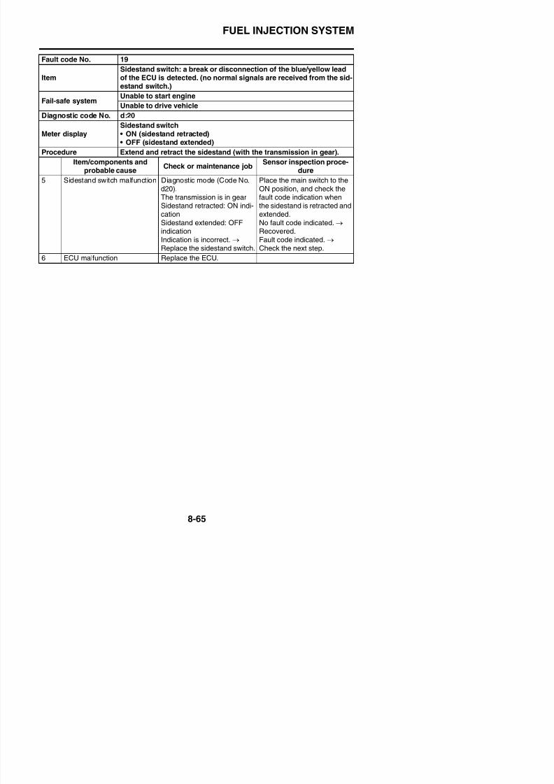
8/21/2019 Fz8 - Service Manual
http://slidepdf.com/reader/full/fz8-service-manual 460/609
Fault code No. 20
Item
Intake air pressure sensor or atmospheric pressure sensor: when
the main switch is set to “ON”, the atmospheric pressure sensorvoltage and intake air pressure sensor voltage differ greatly.
Fail-safe systemAble to start engine
Able to drive vehicle
Diagnostic code No. d:02, d:03
d:02
Meter display Displays the atmospheric pressure.
ProcedureCompare the actually measured atmospheric pressure with the
meter display value.
d:03
Meter display Displays the intake air pressure.
Procedure
Set the engine stop switch to “ ”, and then operate the throttle
while pushing the start switch “ ”. (If the display value changes,
the performance is OK.)
Item/components andprobable cause
Check or maintenance jobSensor inspection proce-
dure
1 Intake air pressure sensormalfunction
Check in the diagnostic mode(Code No. d03).
When engine is stopped:Atmospheric pressure at thecurrent altitude and weatherconditions is indicated.0 m above sea level: Approx.101 kPa3000 m above sea level:Approx. 70 kPaIncorrect indication → Sensormalfunction → Replace theintake air pressure sensor.Sensor inspection procedureRefer to “CHECKING THEINTAKE AIR PRESSURESENSOR” on page 8-201.
Place the main switch to theON position, and check the
fault code indication.No fault code indicated. → Recovered.Fault code indicated. → Check the next step.
2 Atmospheric pressure sensormalfunction
Check in the diagnostic mode(Code No. d02).When engine is stopped:Atmospheric pressure at thecurrent altitude and weather
Place the main switch to theON position, and check thefault code indication.No fault code indicated. → Recovered
FUEL INJECTION SYSTEM
Fault code No. 20
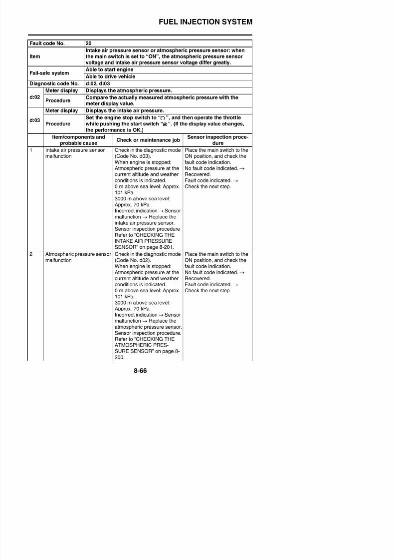
8/21/2019 Fz8 - Service Manual
http://slidepdf.com/reader/full/fz8-service-manual 461/609
3 ECU malfunction Replace the ECU.
Fault code No. 21
ItemCoolant temperature sensor: open or short circuit detected. (no nor-mal signals are received from the coolant temperature sensor.)
Fail-safe systemAble to start engine
Able to drive vehicle
Diagnostic code No. d:06
Meter display Displays the coolant temperature.
ProcedureCompare the actually measured coolant temperature with the meterdisplay value.
Item/components andprobable cause
Check or maintenance jobSensor inspection proce-
dure
1 Connection of coolant tem-perature sensor coupler
Check the connection of thecoupler is secure.Remove the coupler, andcheck each pin (for bending,wear, or locking).
Poor connection → Connect itsecurely, or repair/replace the
wire harness.
Place the main switch to theON position, and check the
fault code indication.No fault code indicated. → Recovered.Fault code indicated. → Check the next step.
Item
Intake air pressure sensor or atmospheric pressure sensor: when
the main switch is set to “ON”, the atmospheric pressure sensorvoltage and intake air pressure sensor voltage differ greatly.
Fail-safe systemAble to start engine
Able to drive vehicle
Diagnostic code No. d:02, d:03
d:02
Meter display Displays the atmospheric pressure.
ProcedureCompare the actually measured atmospheric pressure with the
meter display value.
d:03
Meter display Displays the intake air pressure.
Procedure
Set the engine stop switch to “ ”, and then operate the throttle
while pushing the start switch “ ”. (If the display value changes,
the performance is OK.)
Item/components andprobable cause
Check or maintenance jobSensor inspection proce-
dure
FUEL INJECTION SYSTEM
Fault code No. 21
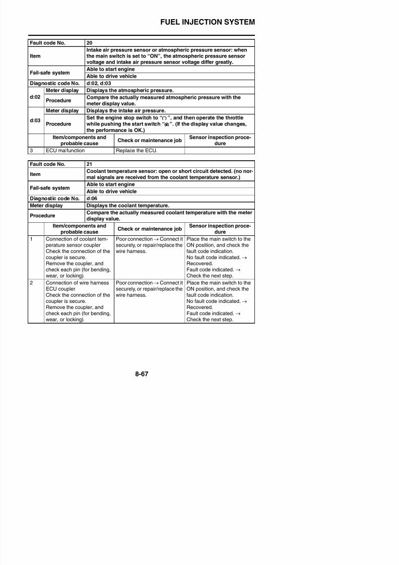
8/21/2019 Fz8 - Service Manual
http://slidepdf.com/reader/full/fz8-service-manual 462/609
3 Connection of fuel injectionsystem sub-wire harnesscouplerCheck the connection of thecoupler is secure.Remove the coupler, and
check each pin (for bending,wear, or locking).
Poor connection → Connect itsecurely, or repair/replace thewire harness.
Place the main switch to theON position, and check thefault code indication.No fault code indicated. → Recovered.Fault code indicated. →
Check the next step.
4 Continuity of wire harness Open or short circuit → Replace the wire harnessBlack/blue–Black/blueGreen/white–Green/white
Place the main switch to theON position, and check thefault code indication.No fault code indicated. → Recovered.Fault code indicated. →
Check the next step.5 Installation status of coolant
temperature sensor
Check the mounting sectionfor a loose or pinched mount-ing.
Make sure that the mountingposition is correct.
Place the main switch to theON position, and check the
fault code indication.No fault code indicated. → Recovered.Fault code indicated. → Check the next step.
6 Coolant temperature sensormalfunction
Check in the diagnostic mode(Code No. d06).
During cold starting: A tem-perature close to the ambienttemperature is indicated
Place the main switch to theON position, and check the
fault code indication.No fault code indicated. → Recovered
ItemCoolant temperature sensor: open or short circuit detected. (no nor-
mal signals are received from the coolant temperature sensor.)
Fail-safe systemAble to start engine
Able to drive vehicle
Diagnostic code No. d:06
Meter display Displays the coolant temperature.
ProcedureCompare the actually measured coolant temperature with the meterdisplay value.
Item/components andprobable cause Check or maintenance job Sensor inspection proce-dure
FUEL INJECTION SYSTEM
Fault code No. 22
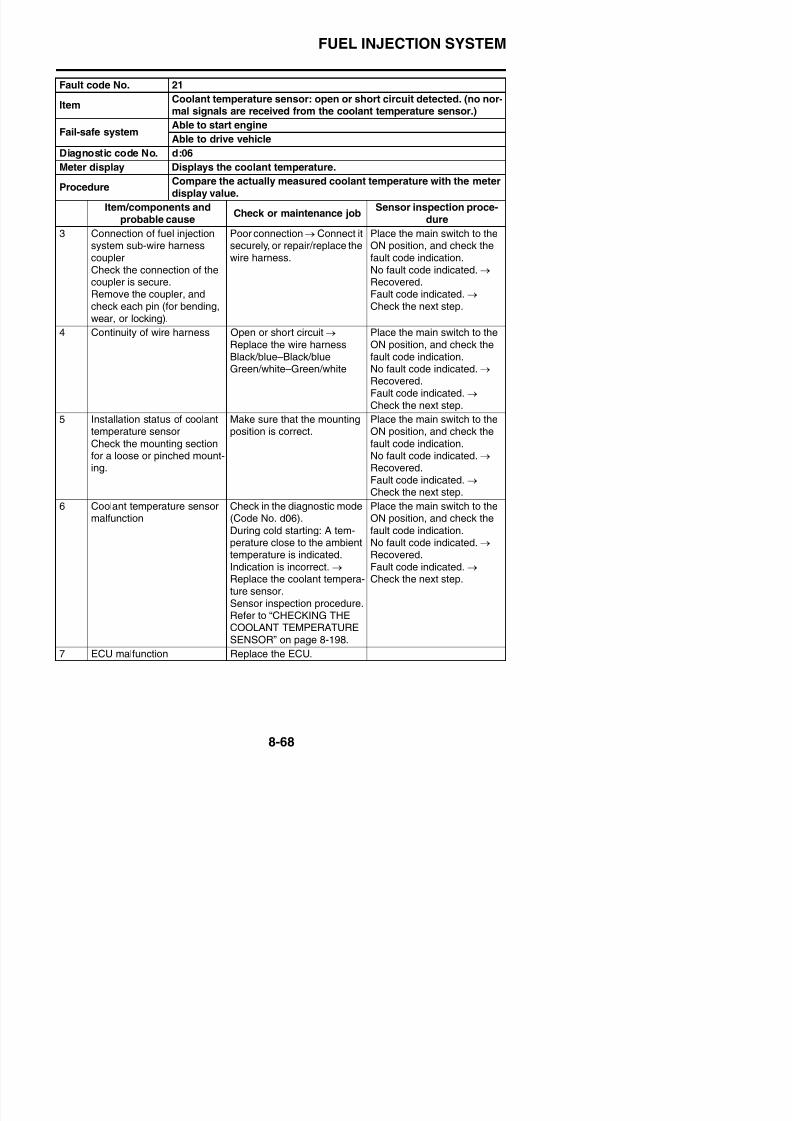
8/21/2019 Fz8 - Service Manual
http://slidepdf.com/reader/full/fz8-service-manual 463/609
ItemIntake air temperature sensor: open or short circuit detected. (no
normal signals are received from the intake air temperature sensor.)
Fail-safe systemAble to start engine
Able to drive vehicle
Diagnostic code No. d:05
Meter display Displays the intake air temperature.
ProcedureCompare the actually measured intake air temperature with themeter display value.
Item/components andprobable cause
Check or maintenance job Sensor inspection proce-dure
1 Connection of intake air tem-perature sensor couplerCheck the connection of thecoupler is secure.Remove the coupler, andcheck each pin (for bending,
wear, or locking).
Poor connection → Connect itsecurely, or repair/replace thewire harness.
Place the main switch to theON position, and check thefault code indication.No fault code indicated. → Recovered.Fault code indicated. →
Check the next step.2 Connection of wire harness
ECU couplerCheck the connection of thecoupler is secure.Remove the coupler, andcheck each pin (for bending,wear, or locking).
Poor connection → Connect itsecurely, or repair/replace thewire harness.
Place the main switch to theON position, and check thefault code indication.No fault code indicated. → Recovered.Fault code indicated. → Check the next step.
3 Continuity of wire harness Open or short circuit → Replace the wire harness.Black/blue–Black/blueBrown/white–Brown/white
Place the main switch to theON position, and check thefault code indication.No fault code indicated. → Recovered.Fault code indicated. → Check the next step.
4 Installation status of intake
air temperature sensorCheck the mounting sectionfor a loose or pinched mount-ing.
Make sure that the mounting
position is correct.
Place the main switch to the
ON position, and check thefault code indication.No fault code indicated. → Recovered.Fault code indicated →
FUEL INJECTION SYSTEM
Fault code No. 22
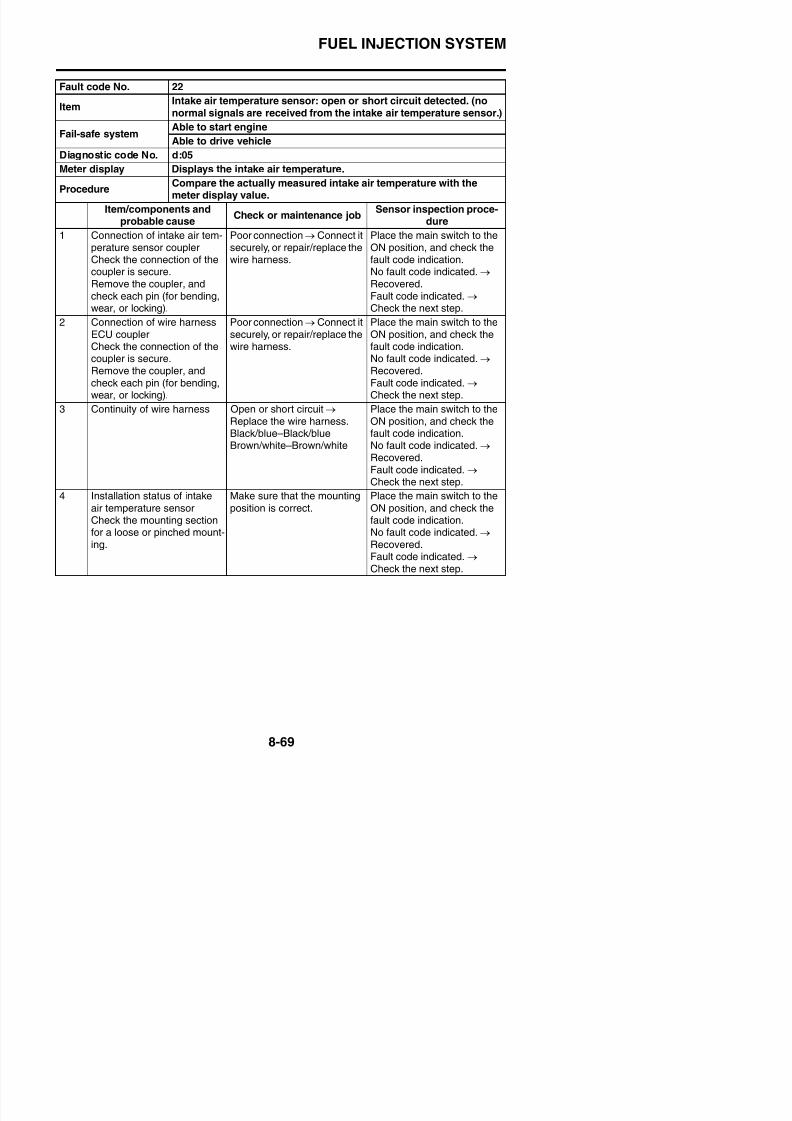
8/21/2019 Fz8 - Service Manual
http://slidepdf.com/reader/full/fz8-service-manual 464/609
5 Intake air temperature sensormalfunction
Check in the diagnostic mode(Code No. d05).Sensor inspection procedureRefer to “CHECKING THEINTAKE AIR TEMPERATURESENSOR” on page 8-202.
During cold starting: A tem-perature close to the ambienttemperature is indicated.After the engine has warmedup, the ambient temperature+20 °C (68 °F) is indicated in
the meter display.Indication is incorrect. →
Replace the intake air tem-perature sensor.
Place the main switch to theON position, and check thefault code indication.No fault code indicated. → Recovered.Fault code indicated. →
Check the next step.
6 ECU malfunction Replace the ECU
Fault code No. 23
ItemAtmospheric pressure sensor: open or short circuit detected. (nonormal signals are received from the atmospheric pressure sensor.)
Fail-safe systemAble to start engine
Able to drive vehicle
Diagnostic code No. d:02
Meter display Displays the atmospheric pressure.
P dCompare the actually measured atmospheric pressure with the
ItemIntake air temperature sensor: open or short circuit detected. (no
normal signals are received from the intake air temperature sensor.)
Fail-safe systemAble to start engine
Able to drive vehicle
Diagnostic code No. d:05
Meter display Displays the intake air temperature.
ProcedureCompare the actually measured intake air temperature with themeter display value.
Item/components andprobable cause Check or maintenance job Sensor inspection proce-dure
FUEL INJECTION SYSTEM
Fault code No. 23
A h i h i i d d (
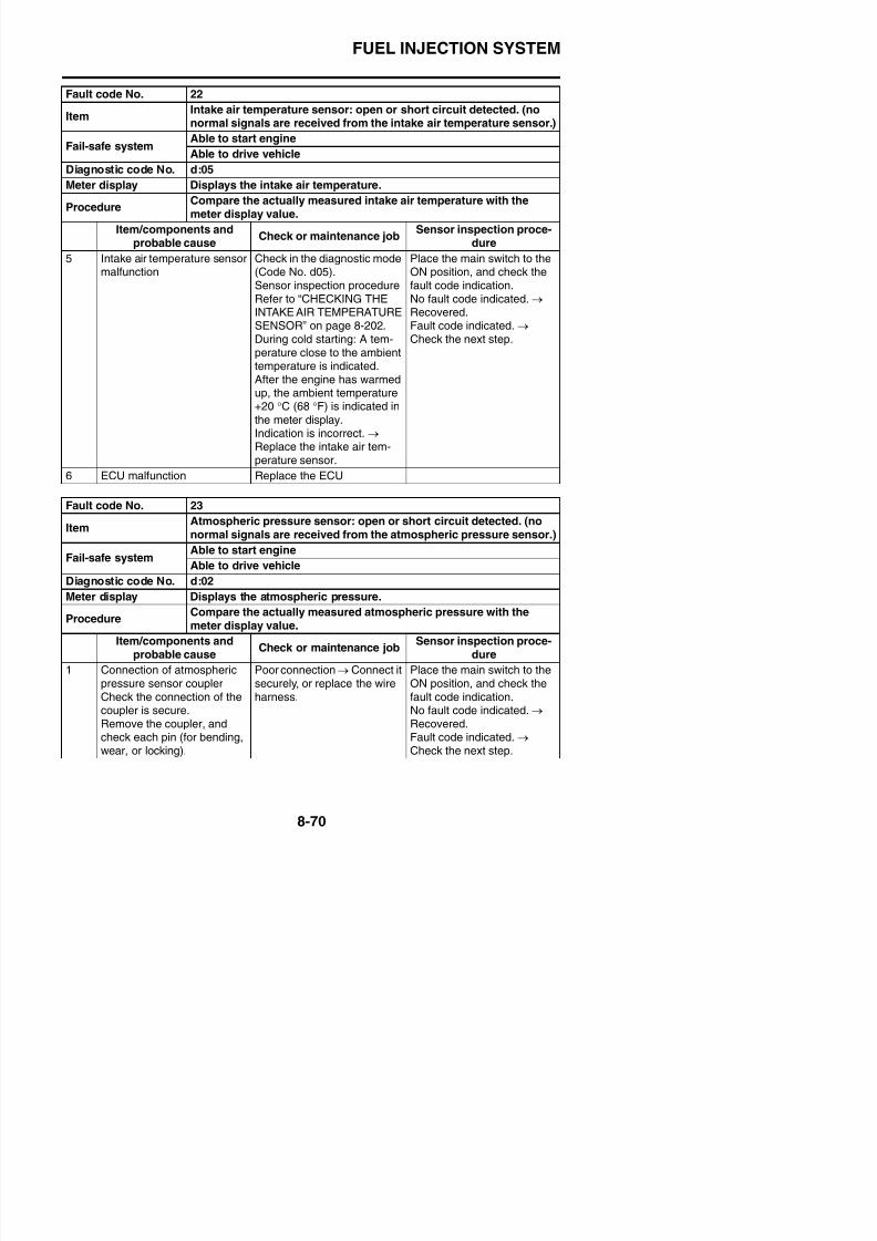
8/21/2019 Fz8 - Service Manual
http://slidepdf.com/reader/full/fz8-service-manual 465/609
2 Connection of wire harnessECU couplerCheck the connection of thecoupler is secure.Remove the coupler andcheck each pin (for bending,
wear, or locking).
Poor connection → Connect itsecurely, or replace the wireharness.
Place the main switch to theON position, and check thefault code indication.No fault code indicated. → Recovered.Fault code indicated. →
Check the next step.3 Continuity of wire harness Open or short circuit → Con-
nect it securely, or replace thewire harness.Black/blue–Black/bluePink–PinkBlue–Blue
Place the main switch to theON position, and check thefault code indication.No fault code indicated. → Recovered.Fault code indicated. → Check the next step.
4 Installation status of atmo-spheric pressure sensorCheck the mounting section
for a loose or pinched mount-ing.
Make sure that the mountingposition is correct.
Place the main switch to theON position, and check thefault code indication.
No fault code indicated. → Recovered.Fault code indicated. → Check the next step.
ItemAtmospheric pressure sensor: open or short circuit detected. (no
normal signals are received from the atmospheric pressure sensor.)
Fail-safe systemAble to start engine
Able to drive vehicle
Diagnostic code No. d:02
Meter display Displays the atmospheric pressure.
ProcedureCompare the actually measured atmospheric pressure with themeter display value.
Item/components andprobable cause Check or maintenance job Sensor inspection proce-dure
FUEL INJECTION SYSTEM
Fault code No. 23
At h i h t i it d t t d (
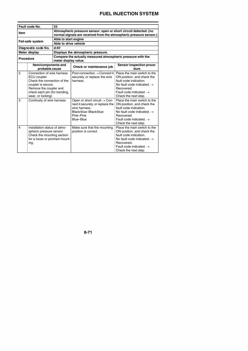
8/21/2019 Fz8 - Service Manual
http://slidepdf.com/reader/full/fz8-service-manual 466/609
5 Atmospheric pressure sensormalfunction
Check in the diagnostic mode(Code No. d02).Atmospheric pressure at thecurrent altitude and weatherconditions is indicated.0 m above sea level: Approx.
101 kPa1000 m above sea level:Approx. 90 kPa2000 m above sea level:Approx. 80 kPa3000 m above sea level:
Approx. 70 kPaIncorrect indication → Sensor
malfunction → Replace theatmospheric pressure sensor.Sensor inspection procedureRefer to “CHECKING THEATMOSPHERIC PRES-SURE SENSOR” on page 8-200.
Place the main switch to theON position, and check thefault code indication.No fault code indicated. → Recovered.Fault code indicated. →
Check the next step.
6 ECU malfunction Replace the ECU.
ItemAtmospheric pressure sensor: open or short circuit detected. (no
normal signals are received from the atmospheric pressure sensor.)
Fail-safe systemAble to start engine
Able to drive vehicle
Diagnostic code No. d:02
Meter display Displays the atmospheric pressure.
ProcedureCompare the actually measured atmospheric pressure with themeter display value.
Item/components andprobable cause Check or maintenance job Sensor inspection proce-dure
FUEL INJECTION SYSTEM
Fault code No. 24
I O l i l i d f th O
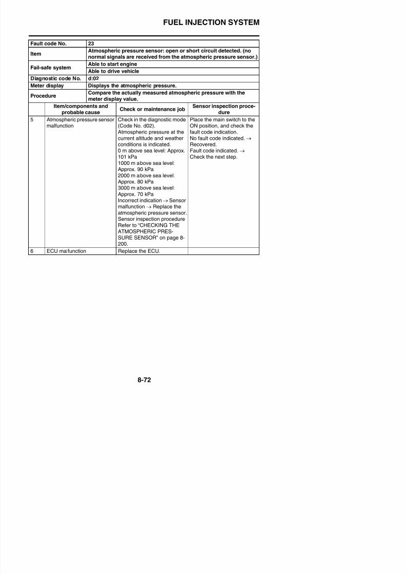
8/21/2019 Fz8 - Service Manual
http://slidepdf.com/reader/full/fz8-service-manual 467/609
Item O2 sensor: no normal signals are received from the O2 sensor.
Fail-safe systemAble to start engineAble to drive vehicle
Diagnostic code No. —
Meter display —
Procedure —
Item/components andprobable cause
Check or maintenance jobSensor inspection proce-
dure
1 O2 sensor installation status Check the sensor for a loosemounting or a pinch
Either start and warm up theengine, and then racing it, orreset it with diagnostic coded63.
No fault code indicated. → Recovered.Fault code indicated. → Check the next step.
2 Connection of O2 sensorcouplerCheck the connection of thecoupler is secure.Remove the coupler, andcheck each pin (for bending,
wear, or locking).
Poor connection → Connect itsecurely, or repair/replace thewire harness.
Either start and warm up theengine, and then racing it, orreset it with diagnostic coded63.No fault code indicated. → Recovered.Fault code indicated. → Check the next step.
3 Connection of wire harnessECU couplerCheck the connection of thecoupler is secure.Remove the coupler, andcheck each pin (for bending,wear, or locking).
Poor connection → Connect itsecurely, or repair/replace thewire harness.
Either start and warm up theengine, and then racing it, orreset it with diagnostic coded63.No fault code indicated. → Recovered.Fault code indicated. → Check the next step.
4 Continuity of wire harness Open or short circuit → Con-nect it securely, or repair/ replace the wire harness.Black/blue–Black/bluePi k/bl k Pi k/bl k
Either start and warm up theengine, and then racing it, orreset it with diagnostic coded63.N f lt d i di t d
FUEL INJECTION SYSTEM
Fault code No. 24
Item O2 sensor: no normal signals are received from the O2 sensor
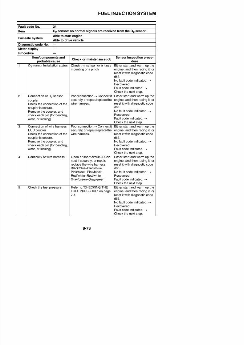
8/21/2019 Fz8 - Service Manual
http://slidepdf.com/reader/full/fz8-service-manual 468/609
6 O2 sensor malfunction Check the O2 sensor for anabnormality.Refer to “ENGINE REMOVAL”on page 5-3.O2 sensor malfunction →
Replace the O2 sensor
Either start and warm up theengine, and then racing it, orreset it with diagnostic coded63.No fault code indicated. → Recovered.Fault code indicated. → Check the next step.
7 ECU malfunction Replace the ECU.
Fault code No. 30
ItemLatch up detected.No normal signals are received from the lean angle sensor.
Fail-safe systemUnable to start engine
Unable to drive vehicle
Diagnostic code No. d:08
Meter displayLean angle sensor output voltage• 0.4–1.4 (upright)
• 3.7–4.4 (overturned)
Procedure Remove the lean angle sensor and incline it more than 65 degrees.
Item/components andprobable cause
Check or maintenance jobSensor inspection proce-
dure
1 Turnover of vehicle Raise the vehicle to theupright position
Place the main switch to theON position.(however, the engine cannotbe restarted unless the mainswitch is first turned OFF)N f lt d i di t d
Item O2 sensor: no normal signals are received from the O2 sensor.
Fail-safe system Able to start engineAble to drive vehicle
Diagnostic code No. —
Meter display —
Procedure —
Item/components andprobable cause
Check or maintenance jobSensor inspection proce-
dure
FUEL INJECTION SYSTEM
Fault code No. 30
Latch up detected.
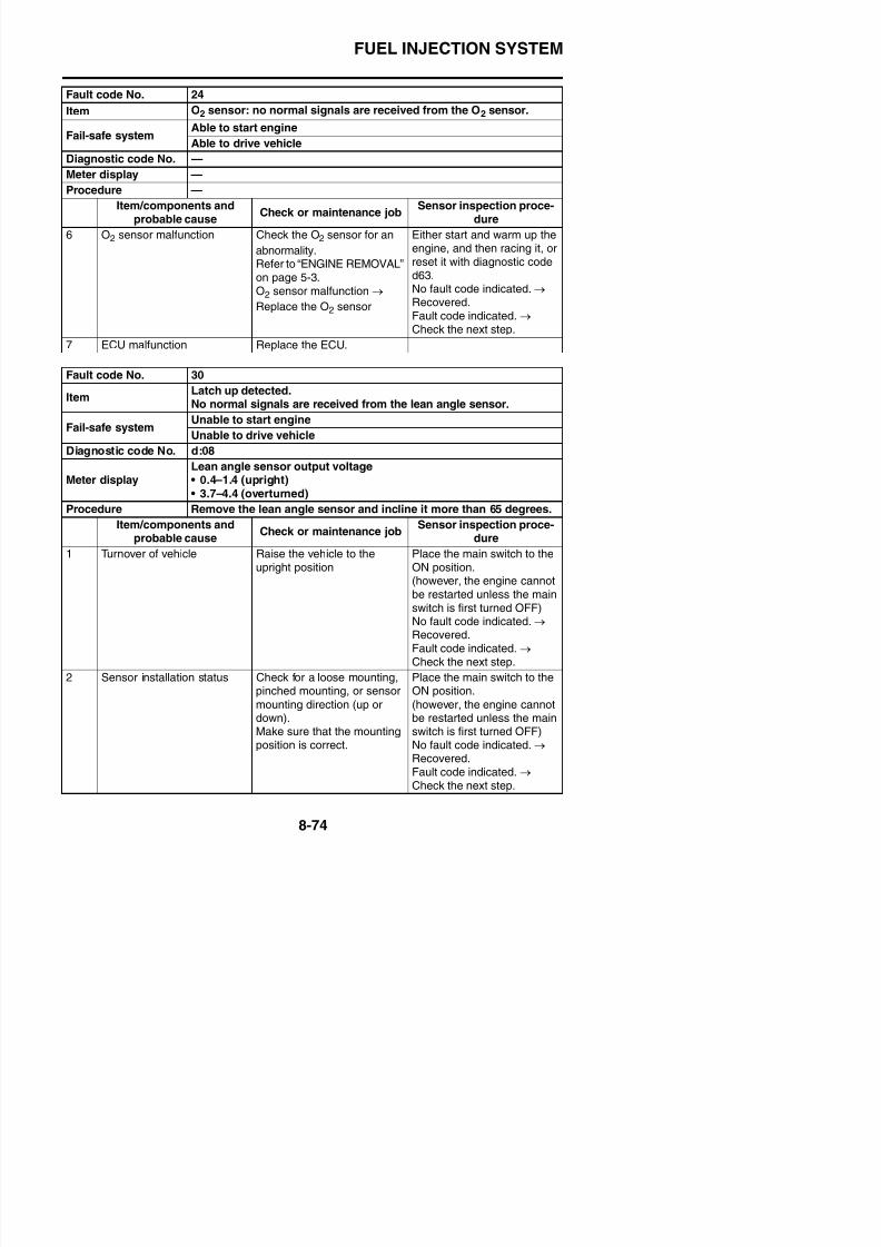
8/21/2019 Fz8 - Service Manual
http://slidepdf.com/reader/full/fz8-service-manual 469/609
3 Lean angle sensor malfunc-tion
Diagnostic mode (Code No.d08).Sensor inspection procedureRefer to “CHECKING THELEAN ANGLE SENSOR” on
page 8-194.In vertical position:0.4–1.4 VWhen turned over:3.7–4.4 VIndication is incorrect. →
Replace the lean angle sen-sor.
Place the main switch to theON position.(however, the engine cannotbe restarted unless the mainswitch is first turned OFF)
No fault code indicated.→
Recovered.Fault code indicated. → Check the next step.
4 ECU malfunction Replace the ECU.
Fault code No. 33
ItemCylinder-#1 ignition coil: open or short circuit detected in the pri-mary lead of the cylinder-#1 ignition coil.
Fail-safe systemAble to start engine (depending on the number of faulty cylinders)
Able to drive vehicle (depending on the number of faulty cylinders)
Diagnostic code No. d:30
ActuationActuates the cylinder-#1 ignition coil five times at one-second inter-vals.Illuminates the engine trouble warning light.
P dCheck that a spark is generated five times.
ItemLatch up detected.
No normal signals are received from the lean angle sensor.
Fail-safe systemUnable to start engine
Unable to drive vehicle
Diagnostic code No. d:08
Meter displayLean angle sensor output voltage• 0.4–1.4 (upright)• 3.7–4.4 (overturned)
Procedure Remove the lean angle sensor and incline it more than 65 degrees.
Item/components andprobable cause
Check or maintenance jobSensor inspection proce-
dure
FUEL INJECTION SYSTEM
Fault code No. 33
ItCylinder-#1 ignition coil: open or short circuit detected in the pri-
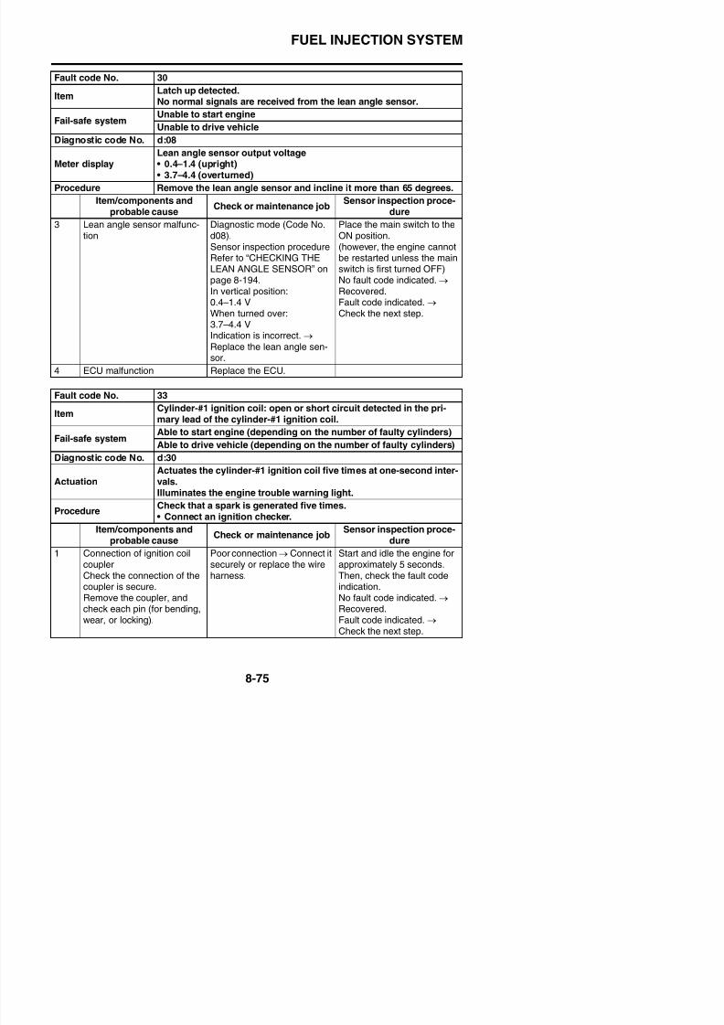
8/21/2019 Fz8 - Service Manual
http://slidepdf.com/reader/full/fz8-service-manual 470/609
2 Connection of wire harnessECU couplerCheck the connection of thecoupler is secure.
Remove the coupler, andcheck each pin (for bending,wear, or locking).
Poor connection → Connect itsecurely or replace the wireharness.
Start and idle the engine forapproximately 5 seconds.Then, check the fault codeindication.
No fault code indicated.→
Recovered.Fault code indicated. → Check the next step.
3 Connection of ignition systemsub-wire harness couplerCheck the connection of thecoupler is secure.
Remove the coupler, andcheck each pin (for bending,wear, or locking).
Poor connection → Connect itsecurely, or repair/replace thewire harness.
Start and idle the engine forapproximately 5 seconds.Then, check the fault codeindication.
No fault code indicated. → Recovered.Fault code indicated. → Check the next step.
4 Continuity of wire harness Open or short circuit → Replace the wire harness.Orange–Orange
Start and idle the engine forapproximately 5 seconds.Then, check the fault codeindication.
No fault code indicated. → Recovered.Fault code indicated. → Check the next step.
5 Ignition coil installation status Make sure that the mounting Start and idle the engine for
ItemCylinder #1 ignition coil: open or short circuit detected in the pri
mary lead of the cylinder-#1 ignition coil.
Fail-safe systemAble to start engine (depending on the number of faulty cylinders)
Able to drive vehicle (depending on the number of faulty cylinders)
Diagnostic code No. d:30
ActuationActuates the cylinder-#1 ignition coil five times at one-second inter-vals.Illuminates the engine trouble warning light.
ProcedureCheck that a spark is generated five times.• Connect an ignition checker.
Item/components andprobable cause
Check or maintenance jobSensor inspection proce-
dure
FUEL INJECTION SYSTEM
Fault code No. 33
ItemCylinder-#1 ignition coil: open or short circuit detected in the pri-

8/21/2019 Fz8 - Service Manual
http://slidepdf.com/reader/full/fz8-service-manual 471/609
6 Ignition coil malfunction(Check the continuity of pri-mary coil.)
Ignition coil inspectionmethodRefer to “CHECKING THEIGNITION COILS” on page 8-
192.
Start and idle the engine forapproximately 5 seconds.Then, check the fault codeindication.
No fault code indicated.→
Recovered.Fault code indicated. → Check the next step.
7 ECU malfunction Check in the diagnostic mode(Code No. d30).If not ignited, replace thedefective ECU.
Fault code No. 34
ItemCylinder-#2 ignition coil: open or short circuit detected in the pri-mary lead of the cylinder-#2 ignition coil.
Fail-safe systemAble to start engine (depending on the number of faulty cylinders)
Able to drive vehicle (depending on the number of faulty cylinders)
Diagnostic code No. d:31
Actuation Actuates the cylinder-#2 ignition coil five times at one-second inter-vals.Illuminates the engine trouble warning light.
ProcedureCheck that a spark is generated five times.• Connect an ignition checker.
Itemy g p p
mary lead of the cylinder-#1 ignition coil.
Fail-safe systemAble to start engine (depending on the number of faulty cylinders)
Able to drive vehicle (depending on the number of faulty cylinders)
Diagnostic code No. d:30
ActuationActuates the cylinder-#1 ignition coil five times at one-second inter-vals.Illuminates the engine trouble warning light.
ProcedureCheck that a spark is generated five times.• Connect an ignition checker.
Item/components andprobable cause
Check or maintenance jobSensor inspection proce-
dure
FUEL INJECTION SYSTEM
Fault code No. 34
ItemCylinder-#2 ignition coil: open or short circuit detected in the pri-
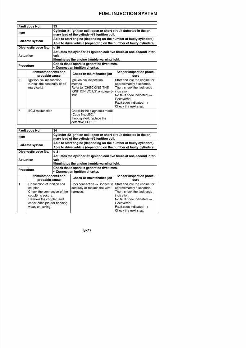
8/21/2019 Fz8 - Service Manual
http://slidepdf.com/reader/full/fz8-service-manual 472/609
2 Connection of wire harnessECU couplerCheck the connection of thecoupler is secure.
Remove the coupler, andcheck each pin (for bending,wear, or locking).
Poor connection → Connect itsecurely or replace the wireharness.
Start and idle the engine forapproximately 5 seconds.Then, check the fault codeindication.
No fault code indicated.→
Recovered.Fault code indicated. → Check the next step.
3 Connection of ignition systemsub-wire harness couplerCheck the connection of thecoupler is secure.
Remove the coupler, andcheck each pin (for bending,wear, or locking).
Poor connection → Connect itsecurely, or replace the wireharness.
Start and idle the engine forapproximately 5 seconds.Then, check the fault codeindication.
No fault code indicated. → Recovered.Fault code indicated. → Check the next step.
4 Continuity of wire harness Open or short circuit → Replace the wire harness.Gray/red–Gray/red
Start and idle the engine forapproximately 5 seconds.Then, check the fault codeindication.
No fault code indicated. → Recovered.Fault code indicated. → Check the next step.
5 Ignition coil installation status Make sure that the mounting Start and idle the engine for
Item
mary lead of the cylinder-#2 ignition coil.Fail-safe system
Able to start engine (depending on the number of faulty cylinders)
Able to drive vehicle (depending on the number of faulty cylinders)
Diagnostic code No. d:31
ActuationActuates the cylinder-#2 ignition coil five times at one-second inter-vals.Illuminates the engine trouble warning light.
ProcedureCheck that a spark is generated five times.• Connect an ignition checker.
Item/components andprobable cause
Check or maintenance jobSensor inspection proce-
dure
FUEL INJECTION SYSTEM
Fault code No. 34
ItemCylinder-#2 ignition coil: open or short circuit detected in the pri-
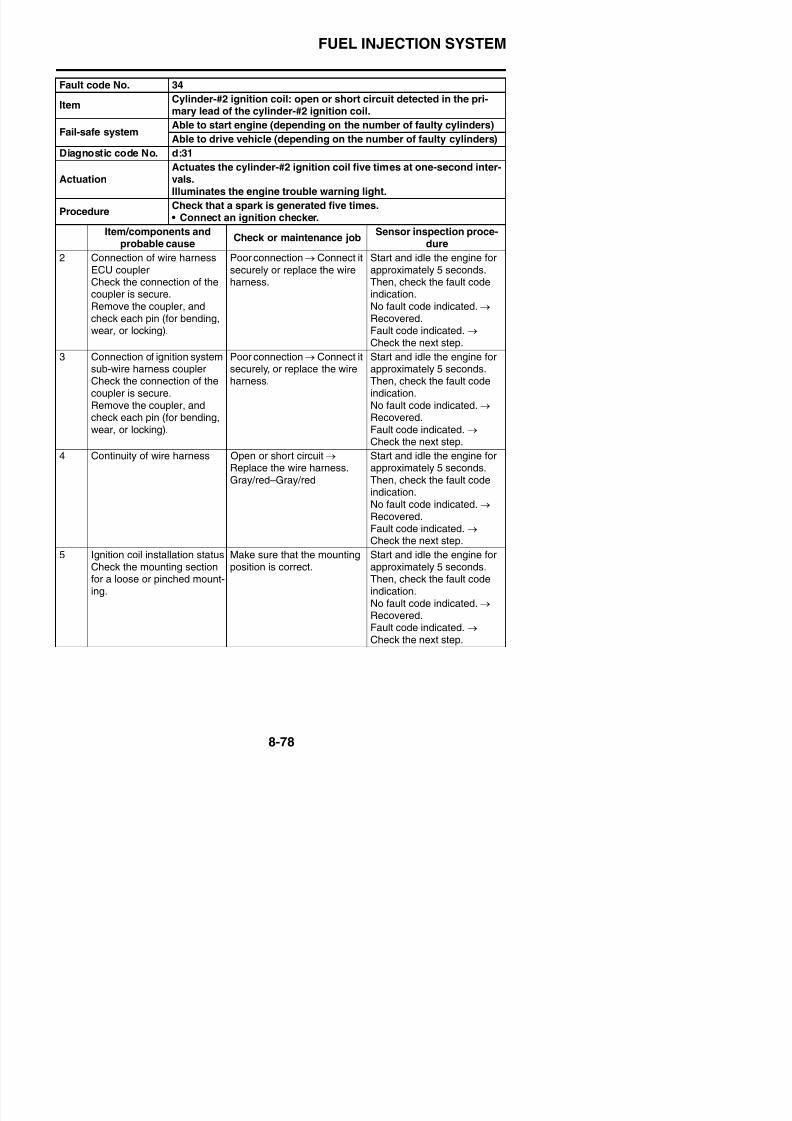
8/21/2019 Fz8 - Service Manual
http://slidepdf.com/reader/full/fz8-service-manual 473/609
6 Ignition coil malfunction(Check the continuity of pri-mary coil.)
Ignition coil inspectionmethodRefer to “CHECKING THEIGNITION COILS” on page 8-
192.
Start and idle the engine forapproximately 5 seconds.Then, check the fault codeindication.
No fault code indicated.→
Recovered.Fault code indicated. → Check the next step.
7 ECU malfunction Check in the diagnostic mode(Code No. d31).If not ignited, replace thedefective ECU.
Fault code No. 35
ItemCylinder-#3 ignition coil: open or short circuit detected in the pri-mary lead of the cylinder-#3 ignition coil.
Fail-safe systemAble to start engine (depending on the number of faulty cylinders)
Able to drive vehicle (depending on the number of faulty cylinders)
Diagnostic code No. d:32
Actuation Actuates the cylinder-#3 ignition coil five times at one-second inter-vals.Illuminates the engine trouble warning light.
ProcedureCheck that a spark is generated five times.• Connect an ignition checker.
Item
mary lead of the cylinder-#2 ignition coil.Fail-safe system
Able to start engine (depending on the number of faulty cylinders)
Able to drive vehicle (depending on the number of faulty cylinders)
Diagnostic code No. d:31
ActuationActuates the cylinder-#2 ignition coil five times at one-second inter-vals.Illuminates the engine trouble warning light.
Procedure
Check that a spark is generated five times.
• Connect an ignition checker.
Item/components andprobable cause
Check or maintenance jobSensor inspection proce-
dure
FUEL INJECTION SYSTEM
Fault code No. 35
ItemCylinder-#3 ignition coil: open or short circuit detected in the pri-

8/21/2019 Fz8 - Service Manual
http://slidepdf.com/reader/full/fz8-service-manual 474/609
2 Connection of wire harnessECU couplerCheck the connection of thecoupler is secure.
Remove the coupler, andcheck each pin (for bending,wear, or locking).
Poor connection → Connect itsecurely or replace the wireharness.
Start and idle the engine forapproximately 5 seconds.Then, check the fault codeindication.
No fault code indicated.→
Recovered.Fault code indicated. → Check the next step.
3 Connection of ignition systemsub-wire harness couplerCheck the connection of thecoupler is secure.
Remove the coupler, andcheck each pin (for bending,wear, or locking).
Poor connection → Connect itsecurely, or replace the wireharness.
Start and idle the engine forapproximately 5 seconds.Then, check the fault codeindication.
No fault code indicated.→
Recovered.Fault code indicated. → Check the next step.
4 Continuity of wire harness Open or short circuit → Replace the wire harness.Orange/green–Orange/green
Start and idle the engine forapproximately 5 seconds.Then, check the fault codeindication.
No fault code indicated. → Recovered.Fault code indicated. → Check the next step.
5 Ignition coil installation status Make sure that the mounting Start and idle the engine for
Item
mary lead of the cylinder-#3 ignition coil.Fail-safe system
Able to start engine (depending on the number of faulty cylinders)
Able to drive vehicle (depending on the number of faulty cylinders)
Diagnostic code No. d:32
ActuationActuates the cylinder-#3 ignition coil five times at one-second inter-vals.Illuminates the engine trouble warning light.
Procedure
Check that a spark is generated five times.
• Connect an ignition checker.
Item/components andprobable cause
Check or maintenance jobSensor inspection proce-
dure
FUEL INJECTION SYSTEM
Fault code No. 35
ItemCylinder-#3 ignition coil: open or short circuit detected in the pri-
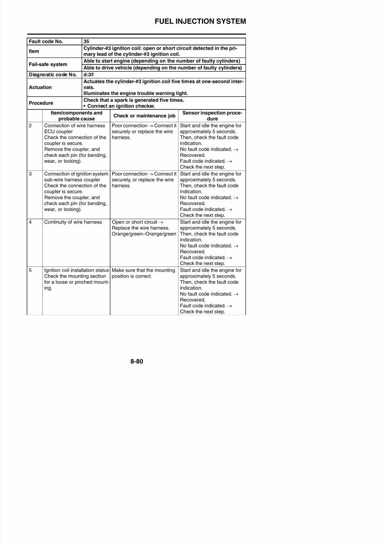
8/21/2019 Fz8 - Service Manual
http://slidepdf.com/reader/full/fz8-service-manual 475/609
6 Ignition coil malfunction(Check the continuity of pri-mary coil.)
Ignition coil inspectionmethodRefer to “CHECKING THEIGNITION COILS” on page 8-
192.
Start and idle the engine forapproximately 5 seconds.Then, check the fault codeindication.
No fault code indicated.→
Recovered.Fault code indicated. → Check the next step.
7 ECU malfunction Check in the diagnostic mode(Code No. d32).If not ignited, replace thedefective ECU.
Fault code No. 36
ItemCylinder-#4 ignition coil: open or short circuit detected in the pri-mary lead of the cylinder-#4 ignition coil.
Fail-safe systemAble to start engine (depending on the number of faulty cylinders)
Able to drive vehicle (depending on the number of faulty cylinders)
Diagnostic code No. d:33
Actuation Actuates the cylinder-#4 ignition coil five times at one-second inter-vals.Illuminates the engine trouble warning light.
ProcedureCheck that a spark is generated five times.• Connect an ignition checker.
mary lead of the cylinder-#3 ignition coil.Fail-safe system
Able to start engine (depending on the number of faulty cylinders)
Able to drive vehicle (depending on the number of faulty cylinders)
Diagnostic code No. d:32
ActuationActuates the cylinder-#3 ignition coil five times at one-second inter-vals.Illuminates the engine trouble warning light.
Procedure
Check that a spark is generated five times.
• Connect an ignition checker.
Item/components andprobable cause
Check or maintenance jobSensor inspection proce-
dure
FUEL INJECTION SYSTEM
Fault code No. 36
ItemCylinder-#4 ignition coil: open or short circuit detected in the pri-mary lead of the cylinder #4 ignition coil

8/21/2019 Fz8 - Service Manual
http://slidepdf.com/reader/full/fz8-service-manual 476/609
2 Connection of wire harnessECU couplerCheck the connection of thecoupler is secure.Remove the coupler, andcheck each pin (for bending,wear, or locking).
Poor connection → Connect itsecurely or replace the wireharness.
Start and idle the engine forapproximately 5 seconds.Then, check the fault codeindication.No fault code indicated. → Recovered.Fault code indicated. → Check the next step.
3 Connection of ignition systemsub-wire harness couplerCheck the connection of thecoupler is secure.
Remove the coupler, andcheck each pin (for bending,wear, or locking).
Poor connection → Connect itsecurely, or replace the wireharness.
Start and idle the engine forapproximately 5 seconds.Then, check the fault codeindication.
No fault code indicated.→
Recovered.Fault code indicated. → Check the next step.
4 Continuity of wire harness Open or short circuit → Replace the wire harness.Gray/green–Gray/green
Start and idle the engine forapproximately 5 seconds.Then, check the fault codeindication.
No fault code indicated. → Recovered.Fault code indicated. → Check the next step.
5 Ignition coil installation status Make sure that the mounting Start and idle the engine for
mary lead of the cylinder-#4 ignition coil.
Fail-safe systemAble to start engine (depending on the number of faulty cylinders)
Able to drive vehicle (depending on the number of faulty cylinders)
Diagnostic code No. d:33
ActuationActuates the cylinder-#4 ignition coil five times at one-second inter-vals.Illuminates the engine trouble warning light.
Procedure
Check that a spark is generated five times.
• Connect an ignition checker.
Item/components andprobable cause
Check or maintenance jobSensor inspection proce-
dure
FUEL INJECTION SYSTEM
Fault code No. 36
ItemCylinder-#4 ignition coil: open or short circuit detected in the pri-mary lead of the cylinder-#4 ignition coil

8/21/2019 Fz8 - Service Manual
http://slidepdf.com/reader/full/fz8-service-manual 477/609
6 Ignition coil malfunction(Check the continuity of pri-mary coil.)
Ignition coil inspectionmethodRefer to “CHECKING THEIGNITION COILS” on page 8-192.
Start and idle the engine forapproximately 5 seconds.Then, check the fault codeindication.No fault code indicated. → Recovered.Fault code indicated. → Check the next step.
7 ECU malfunction Check in the diagnostic mode(Code No. d33).If not ignited, replace thedefective ECU.
mary lead of the cylinder-#4 ignition coil.
Fail-safe systemAble to start engine (depending on the number of faulty cylinders)
Able to drive vehicle (depending on the number of faulty cylinders)
Diagnostic code No. d:33
ActuationActuates the cylinder-#4 ignition coil five times at one-second inter-vals.Illuminates the engine trouble warning light.
Procedure
Check that a spark is generated five times.
• Connect an ignition checker.
Item/components andprobable cause
Check or maintenance jobSensor inspection proce-
dure
FUEL INJECTION SYSTEM
Fault code No. 39
ItemInjector: open circuit detected. (no normal signals are received from
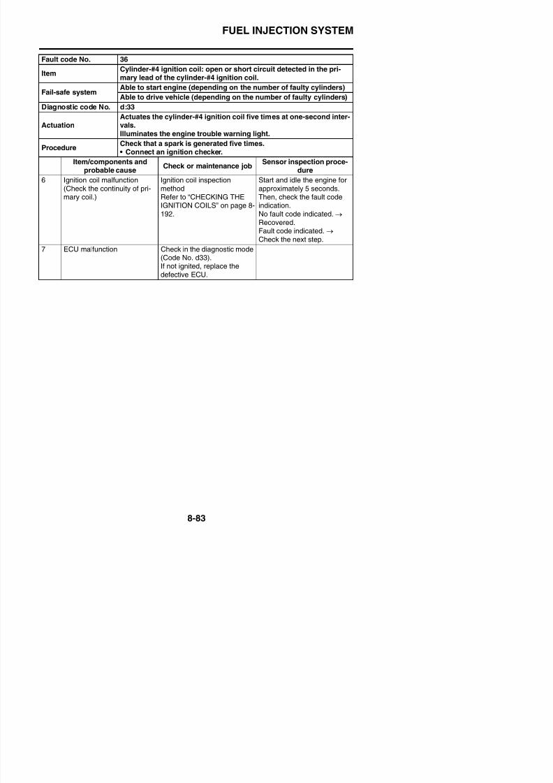
8/21/2019 Fz8 - Service Manual
http://slidepdf.com/reader/full/fz8-service-manual 478/609
the injector.)
Fail-safe systemAble to start engine (depending on the number of faulty cylinders)
Able to drive vehicle (depending on the number of faulty cylinders)
Diagnostic code No. d:36, d:37, d:38, d:39
d:36
ActuationActuates injector #1 five times at one-second intervals.Illuminates the engine trouble warning light.
ProcedureCheck that injector #1 is actuated five times by listening for theoperating sound.
d:37
ActuationActuates injector #2 five times at one-second intervals.Illuminates the engine trouble warning light.
ProcedureCheck that injector #2 is actuated five times by listening for theoperating sound.
d:38
ActuationActuates injector #3 five times at one-second intervals.Illuminates the engine trouble warning light.
ProcedureCheck that injector #3 is actuated five times by listening for the
operating sound.
d:39
ActuationActuates injector #4 five times at one-second intervals.Illuminates the engine trouble warning light.
ProcedureCheck that injector #4 is actuated five times by listening for theoperating sound.
Item/components and
probable causeCheck or maintenance job
Sensor inspection proce-
dure
1 Locate the malfunction Check in the diagnostic mode(Code No. d36, d37, d38,d39).Locate the injector with nooperating noise. Carry out thefollowing checks to the defec-tive injector coupler, wire har-ness, and injector.
—
2 Connection of injector cou-plerCheck the connection of thecoupler is secure.Remove the coupler, and
Poor connection→
Connect itsecurely, or repair/replace thewire harness.
Start and idle the engine forapproximately 5 seconds.Then, check the fault codeindication.No fault code indicated. →
FUEL INJECTION SYSTEM
Fault code No. 39
ItemInjector: open circuit detected. (no normal signals are received fromthe injector.)
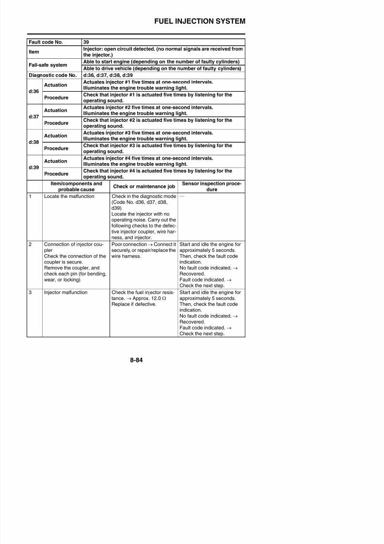
8/21/2019 Fz8 - Service Manual
http://slidepdf.com/reader/full/fz8-service-manual 479/609
4 Connection of wire harnessECU couplerCheck the connection of thecoupler is secure.Remove the coupler andcheck each pin (for bending,wear, or locking).
Poor connection → Connect itsecurely, or repair/replace thewire harness.
Start and idle the engine forapproximately 5 seconds.Then, check the fault codeindication.No fault code indicated. → Recovered.Fault code indicated. → Check the next step.
5 Connection of fuel injectionsystem sub-wire harnesscouplerCheck the connection of thecoupler is secure.
Poor connection → Connect itsecurely, or repair/replace thewire harness.
Start and idle the engine forapproximately 5 seconds.Then, check the fault codeindication.No fault code indicated. →
j )
Fail-safe systemAble to start engine (depending on the number of faulty cylinders)
Able to drive vehicle (depending on the number of faulty cylinders)
Diagnostic code No. d:36, d:37, d:38, d:39
d:36
ActuationActuates injector #1 five times at one-second intervals.Illuminates the engine trouble warning light.
ProcedureCheck that injector #1 is actuated five times by listening for theoperating sound.
d:37
ActuationActuates injector #2 five times at one-second intervals.Illuminates the engine trouble warning light.
ProcedureCheck that injector #2 is actuated five times by listening for theoperating sound.
d:38
ActuationActuates injector #3 five times at one-second intervals.Illuminates the engine trouble warning light.
ProcedureCheck that injector #3 is actuated five times by listening for the
operating sound.
d:39
ActuationActuates injector #4 five times at one-second intervals.Illuminates the engine trouble warning light.
ProcedureCheck that injector #4 is actuated five times by listening for theoperating sound.
Item/components andprobable cause
Check or maintenance jobSensor inspection proce-
dure
FUEL INJECTION SYSTEM
Fault code No. 39
ItemInjector: open circuit detected. (no normal signals are received fromthe injector.)
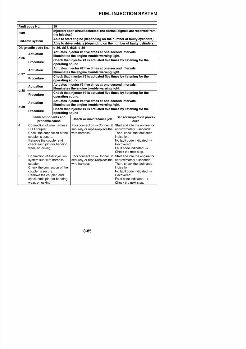
8/21/2019 Fz8 - Service Manual
http://slidepdf.com/reader/full/fz8-service-manual 480/609
6 Continuity of wire harness Open or short circuit → Con-nect it securely, or repair/ replace the wire harness.Fuel injector #1Red/blue–Red/blueRed/black–Red/blackFuel injector #2Red/blue–Red/blueGreen/black–Green/black
Fuel injector #3Red/blue–Red/blueBlue/black–Blue/blackFuel injector #4
Start and idle the engine forapproximately 5 seconds.Then, check the fault codeindication.No fault code indicated. → Recovered.Fault code indicated. → Check the next step.
j )
Fail-safe systemAble to start engine (depending on the number of faulty cylinders)
Able to drive vehicle (depending on the number of faulty cylinders)
Diagnostic code No. d:36, d:37, d:38, d:39
d:36
ActuationActuates injector #1 five times at one-second intervals.Illuminates the engine trouble warning light.
ProcedureCheck that injector #1 is actuated five times by listening for theoperating sound.
d:37
ActuationActuates injector #2 five times at one-second intervals.Illuminates the engine trouble warning light.
ProcedureCheck that injector #2 is actuated five times by listening for theoperating sound.
d:38
ActuationActuates injector #3 five times at one-second intervals.Illuminates the engine trouble warning light.
ProcedureCheck that injector #3 is actuated five times by listening for the
operating sound.
d:39
ActuationActuates injector #4 five times at one-second intervals.Illuminates the engine trouble warning light.
ProcedureCheck that injector #4 is actuated five times by listening for theoperating sound.
Item/components andprobable cause
Check or maintenance jobSensor inspection proce-
dure
FUEL INJECTION SYSTEM
Fault code No. 41
ItemLean angle sensor: open or short circuit detected. (no normal sig-
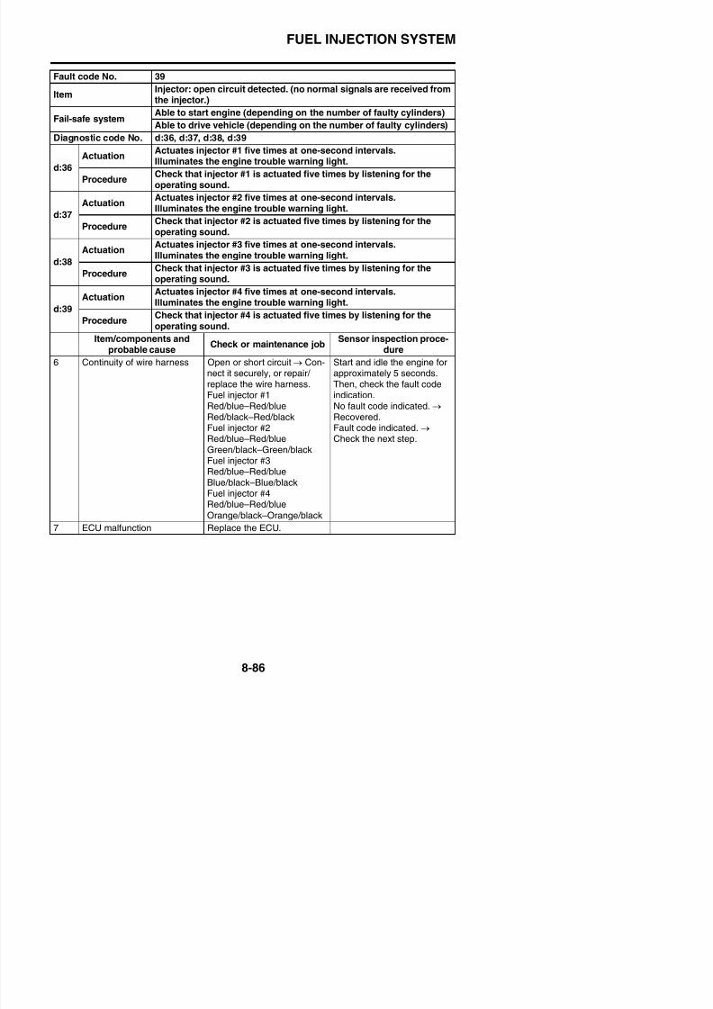
8/21/2019 Fz8 - Service Manual
http://slidepdf.com/reader/full/fz8-service-manual 481/609
nals are received from the lean angle sensor.)Fail-safe system
Unable to start engine
Unable to drive vehicle
Diagnostic code No. d:08
Meter displayLean angle sensor output voltage• 0.4–1.4 (upright)• 3.7–4.4 (overturned)
Procedure Remove the lean angle sensor and incline it more than 65 degrees.
Item/components andprobable cause
Check or maintenance jobSensor inspection proce-
dure
1 Connection of lean anglesensor couplerCheck the connection of thecoupler is secure.Remove the coupler, and
check each pin (for bending,wear, or locking).
Poor connection → Connect itsecurely, or repair/replace thewire harness.
Rotate the main switch to theOFF position first, and thenrotate it to the ON positionagain.Then, check the fault code
indication.No fault code indicated. → Recovered.Fault code indicated. → Check the next step.
2 Connection of wire harnessECU couplerCheck the connection of the
coupler is secure.Remove the coupler, andcheck each pin (for bending,
wear, or locking).
Poor connection → Connect itsecurely, or repair/replace theharness.
Rotate the main switch to theOFF position first, and thenrotate it to the ON position
again.Then, check the fault codeindication.
No fault code indicated. → Recovered.Fault code indicated. → Check the next step.
3 Continuity of wire harness Open or short circuit →
Replace the wire harness.Black/blue–Black/blueYellow/green–Yellow/greenBlue–Blue
Rotate the main switch to the
OFF position first, and thenrotate it to the ON positionagain.Then, check the fault codeindication
FUEL INJECTION SYSTEM
Fault code No. 41
ItemLean angle sensor: open or short circuit detected. (no normal sig-nals are received from the lean angle sensor.)
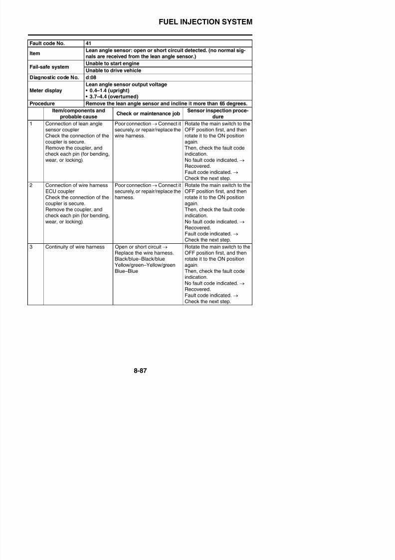
8/21/2019 Fz8 - Service Manual
http://slidepdf.com/reader/full/fz8-service-manual 482/609
4 Lean angle sensor malfunc-tion
Diagnostic mode (Code No.d08).Sensor inspection procedureRefer to “CHECKING THELEAN ANGLE SENSOR” onpage 8-194.
Rotate the main switch to theOFF position first, and thenrotate it to the ON positionagain.Then, check the fault codeindication.No fault code indicated. → Recovered.Fault code indicated. → Check the next step.
5 ECU malfunction Replace the ECU.
Fail-safe systemUnable to start engine
Unable to drive vehicle
Diagnostic code No. d:08
Meter displayLean angle sensor output voltage• 0.4–1.4 (upright)• 3.7–4.4 (overturned)
Procedure Remove the lean angle sensor and incline it more than 65 degrees.
Item/components andprobable cause
Check or maintenance jobSensor inspection proce-
dure
FUEL INJECTION SYSTEM
Fault code No. 42
A. no normal signals are received from the rear wheel sensor.
B open or short circuit is detected in the neutral circuit of the
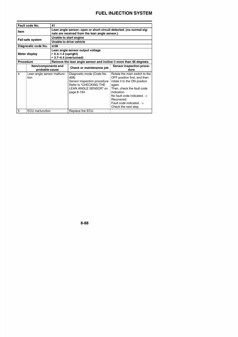
8/21/2019 Fz8 - Service Manual
http://slidepdf.com/reader/full/fz8-service-manual 483/609
Item B. open or short circuit is detected in the neutral circuit of theneutral switch.
C. open or short circuit is detected in the clutch circuit of theclutch switch.
A
Fail-safe systemAble to start engine
Able to drive vehicle
Diagnostic code No. d:07
Meter display Vehicle speed pulses: 0–999
ProcedureCheck that the number increases when the rear wheel is rotated.The number is cumulative and does not reset each time thewheel is stopped.
B
Fail-safe systemAble to start engine
Able to drive vehicle
Diagnostic code No. d:21
Meter display
Neutral switch
• ON (neutral)• OFF (in gear)
Procedure Shift the transmission and clutch lever.
C
Fail-safe systemAble to start engine
Able to drive vehicle
Diagnostic code No. d:21
Meter display
Clutch switch
ON (Gear is in other than neutral, operating clutch and storingsidestand.)OFF (Gear is in other than neutral, operating clutch and usingsidestand.)
Procedure Shift the transmission, clutch lever and sidestand.
Item/components andprobable cause
Check or maintenance jobSensor inspec-tion procedure
Locate the malfunction. Check in the diagnostic mode (Code No. d07).
Rotate the rear wheel and make sure that the indi-cation value increases. Malfunction → Go to the“Rear wheel sensor system malfunction” sectionbelow.
—
FUEL INJECTION SYSTEM
A. Rear wheel sensor system malfunction
Item/components andprobable cause
Check or maintenance jobSensor inspection proce-
dure
1 C ti f h l P ti C t it Ch k i th di ti d
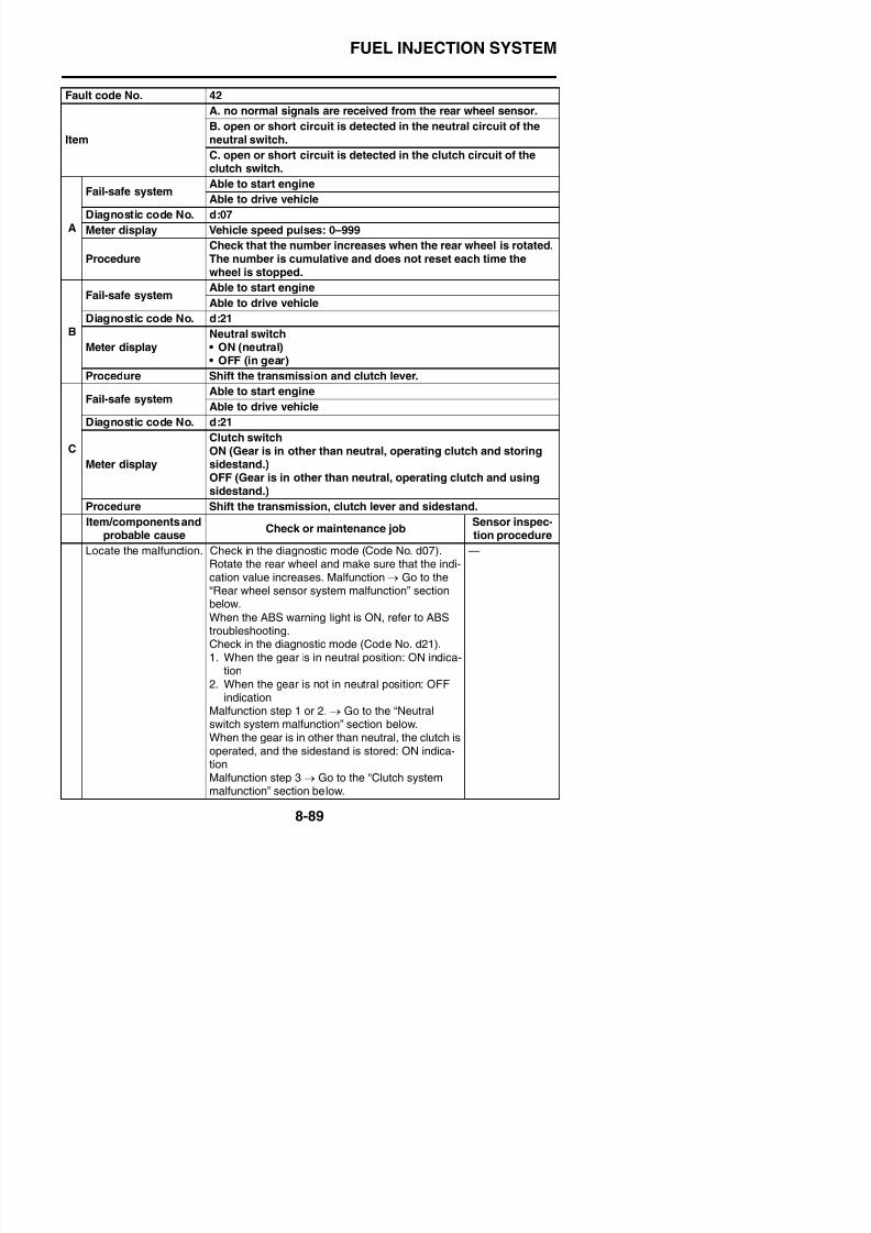
8/21/2019 Fz8 - Service Manual
http://slidepdf.com/reader/full/fz8-service-manual 484/609
1 Connection of rear wheelsensor (meter) couplerCheck the connection of thecoupler is secure.Remove the coupler, and
check each pin (for bending,wear, or locking).
Poor connection → Connect itsecurely, or repair/replace thewire harness.
Check in the diagnostic code(Code No. d07). With the rearwheel rotated, check thepulse input.Then, check the fault code
indication.No fault code indicated. → Recovered.Fault code indicated. → Check the next step.
2 Connection of wire harnessECU coupler
Check the connection of thecoupler is secure.Remove the coupler, and
check each pin (for bending,wear, or locking).
Poor connection → Connect itsecurely, or repair/replace thewire harness.
Check in the diagnostic code(Code No. d07). With the rearwheel rotated, check thepulse input.Then, check the fault code
indication.No fault code indicated. → Recovered.Fault code indicated. → Check the next step.
3 Continuity of wire harness Open or short circuit → Replace the wire harness.White/red–White/red
White–WhiteBlue/white–Blue/white
White/yellow–White/yellow
Check in the diagnostic code(Code No. d07). With the rearwheel rotated, check the
pulse input.Then, check the fault code
indication.No fault code indicated. → Recovered.Fault code indicated. → Check the next step.
4 Rear wheel sensor malfunc-
tion
Sensor inspection procedure
Refer to “MAINTENANCE OFTHE REAR WHEEL SEN-SOR AND SENSOR ROTOR”on page 4-25.Replace if defective
Check in the diagnostic code
(Code No. d07). With the rearwheel rotated, check thepulse input.Then, check the fault codeindication
FUEL INJECTION SYSTEM
5 ECU malfunction Replace the ECU. Check in the diagnostic code(Code No d07) With the rear
Item/components andprobable cause
Check or maintenance jobSensor inspection proce-
dure
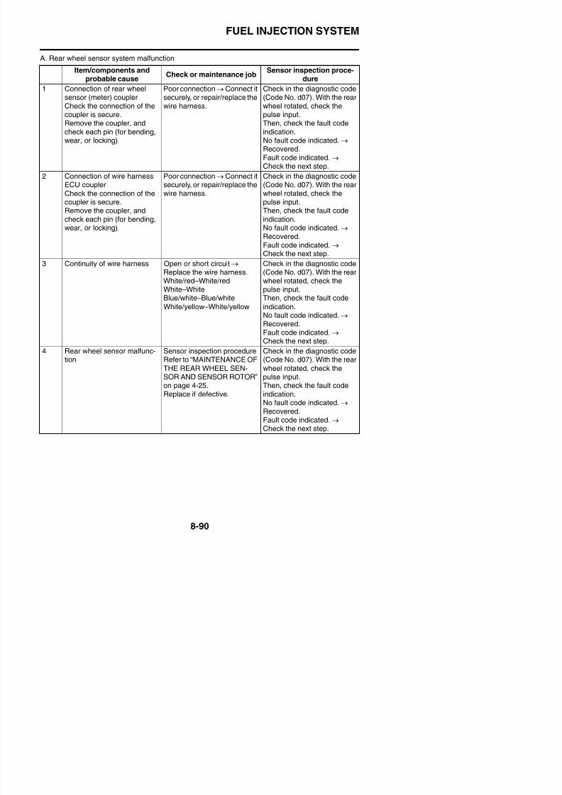
8/21/2019 Fz8 - Service Manual
http://slidepdf.com/reader/full/fz8-service-manual 485/609
B. Neutral switch system malfunction
(Code No. d07). With the rearwheel rotated, check thepulse input.Then, check the fault codeindication.No fault code indicated. → Recovered.
Fault code indicated. →
Check the next step.
6 ABS unit malfunction Replace the ABS unit. Start the engine.Ride on the vehicle at a lowspeed (approx 20–30 km/h).
Item/components and
probable cause
Check or maintenance jobSensor inspection proce-
dure1 Connection of neutral switch
sensor couplerCheck the connection of thecoupler is secure.Remove the coupler, andcheck each pin (for bending,wear, or locking).
Poor connection → Recon-nect or repair the coupler.
Start the engine.Ride the vehicle at a lowspeed (approx. 20–30 km/h).Then, check the fault codeindication.No fault code indicated. → Recovered.
Fault code indicated. → Check the next step.
2 Connection of wire harnessECU couplerCheck the connection of thecoupler is secure.Remove the coupler, andcheck each pin (for bending,
wear, or locking).
Poor connection → Recon-nect or repair the coupler.
Start the engine.Ride the vehicle at a lowspeed (approx. 20–30 km/h).Then, check the fault codeindication.No fault code indicated. →
Recovered.Fault code indicated. → Check the next step.
3 Continuity of wire harness Open or short circuit → R l th i h
Start the engine.Rid th hi l t l
FUEL INJECTION SYSTEM
4 Continuity of leads between
neutral switch and relay unit
Open or short circuit →
Replace the wire harness
Start the engine.
Ride the vehicle at a low
Item/components andprobable cause
Check or maintenance jobSensor inspection proce-
dure
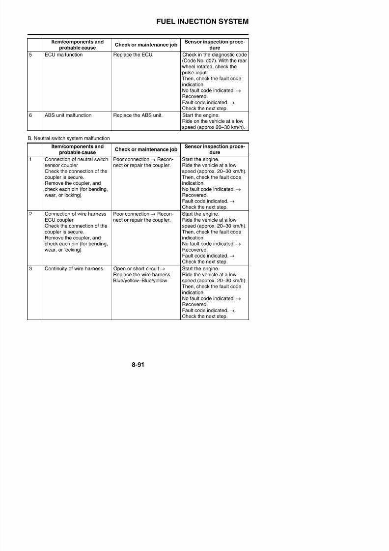
8/21/2019 Fz8 - Service Manual
http://slidepdf.com/reader/full/fz8-service-manual 486/609
C. Clutch switch system malfunction
neutral switch and relay unitcoupler
Replace the wire harness.Sky blue–Sky blue
Ride the vehicle at a lowspeed (approx. 20–30 km/h).Then, check the fault codeindication.No fault code indicated. → Recovered.Fault code indicated. →
Check the next step.
5 Neutral switch malfunction Switch inspection procedureRefer to “CHECKING THESWITCHES” on page 8-179.Replace if defective.
Start the engine.Ride the vehicle at a lowspeed (approx. 20–30 km/h).Then, check the fault codeindication.No fault code indicated. → Recovered.Fault code indicated. → Check the next step.
6 Shift drum (that detects theneutral position) malfunction
Check the gear shift drum(that detects the neutral posi-tion).Refer to “CHECKING THESHIFT DRUM ASSEMBLY”on page 5-90.Malfunction → Replace theshift drum.
Start the engine.Ride the vehicle at a lowspeed (approx. 20–30 km/h).Then, check the fault codeindication.No fault code indicated. → Recovered.Fault code indicated. → Check the next step.
7 ECU malfunction Replace the ECU.
Item/components andprobable cause
Check or maintenance jobSensor inspection proce-
dure
1 Adjusting the clutch lever freeplay
Refer to “ADJUSTING THECLUTCH CABLE FREEPLAY” on page 3-13.
Start the engine.Ride the vehicle at a lowspeed (approx. 20–30 km/h).Then, check the fault codei di ti
FUEL INJECTION SYSTEM
3 Connection of wire harness
ECU coupler
Poor connection → Connect it
securely, or repair/replace the
Start the engine.
Ride the vehicle at a low
Item/components andprobable cause
Check or maintenance jobSensor inspection proce-
dure
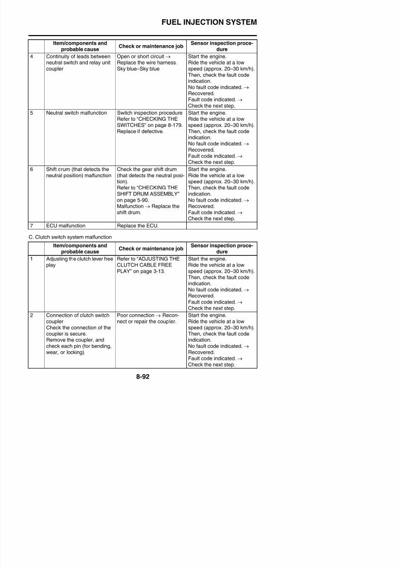
8/21/2019 Fz8 - Service Manual
http://slidepdf.com/reader/full/fz8-service-manual 487/609
ECU couplerCheck the connection of thecoupler is secure.Remove the coupler, andcheck each pin (for bending,wear, or locking).
securely, or repair/replace thewire harness.
Ride the vehicle at a lowspeed (approx. 20–30 km/h).Then, check the fault codeindication.No fault code indicated. → Recovered.Fault code indicated. → Check the next step.
4 Continuity of wire harness Open or short circuit → Replace the wire harness.Yellow/black–Yellow/blackBlue/yellow–Blue/yellow
Start the engine.Ride the vehicle at a lowspeed (approx. 20–30 km/h).Then, check the fault codeindication.No fault code indicated. → Recovered.Fault code indicated. → Check the next step.
5 Continuity of leads betweenclutch switch and relay unitcoupler
Open or short circuit → Replace the wire harness.Yellow/black–Yellow/black
Start the engine.Ride the vehicle at a lowspeed (approx. 20–30 km/h).Then, check the fault codeindication.No fault code indicated. → Recovered.Fault code indicated. → Check the next step.
6 Clutch switch malfunction Check the clutch switch.Refer to “CHECKING THESWITCHES” on page 8-179.Replace if defective.
Start the engine.Ride the vehicle at a lowspeed (approx. 20–30 km/h).Then, check the fault codeindication.
No fault code indicated.→
Recovered.Fault code indicated. → Check the next step.
7 ECU malfunction Replace the ECU
FUEL INJECTION SYSTEM
Fault code No. 43
ItemFuel system voltage: incorrect voltage supplied to the fuel injector,fuel pump and main relay.
Able to start engine
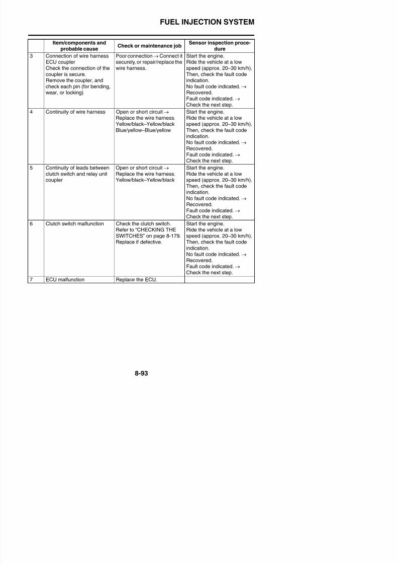
8/21/2019 Fz8 - Service Manual
http://slidepdf.com/reader/full/fz8-service-manual 488/609
Fail-safe systemAble to start engine
Able to drive vehicle
Diagnostic code No. d:09, d:50
d:09
Meter displayFuel system voltage (battery voltage)Approximately 12.0
Procedure
Set the engine stop switch to “ ”, and then compare the actually
measured battery voltage with the meter display value. (If the actu-
ally measured battery voltage is low, recharge the battery.)
d:50
Actuation
Actuates the main relay five times at one-second intervals.Illuminates the engine trouble warning light. (The engine troublewarning light is off when the relay is on, and the engine troublewarning light is on when the relay is off.)
ProcedureCheck that the main relay is actuated five times by listening for theoperating sound.
Item/components andprobable cause Check or maintenance job Sensor inspection proce-dure
1 Connection of main relaycouplerCheck the connection of thecoupler is secure.Remove the coupler, andcheck each pin (for bending,
wear, or locking).
Poor connection → Connect itsecurely, or repair/replace thewire harness.
Place the main switch to theON position for approxi-mately 5 seconds.Then, check the fault codeindication.No fault indicated. → Recov-
ered.Fault code indicated. →
Check the next step.
2 Connection of wire harnessECU couplerCheck the connection of thecoupler is secure.Remove the coupler, and
check each pin (for bending,wear, or locking).
Poor connection → Connect itsecurely, or repair/replace thewire harness.
Place the main switch to theON position for approxi-mately 5 seconds.Then, check the fault codeindication.
No fault indicated. → Recov-ered.Fault code indicated. → Check the next step.
3 C ti it f i h O h t i it Pl th i it h t th
FUEL INJECTION SYSTEM
Fault code No. 43
ItemFuel system voltage: incorrect voltage supplied to the fuel injector,fuel pump and main relay.
F il f tAble to start engine
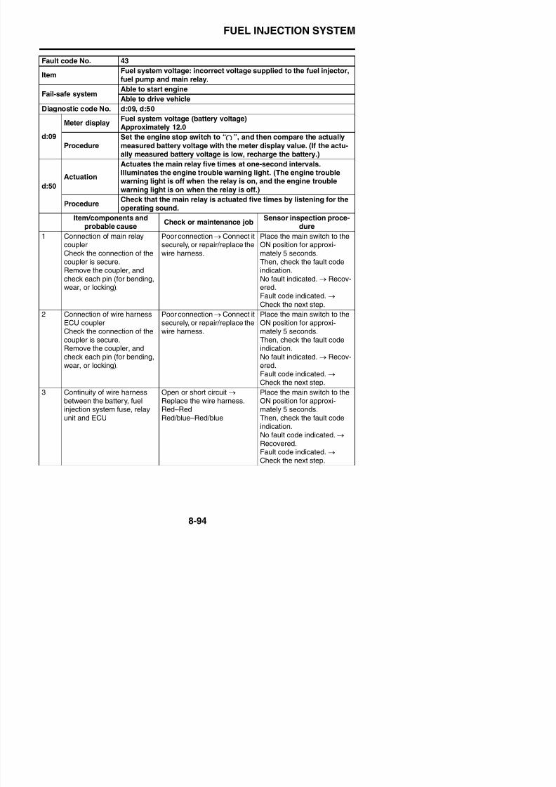
8/21/2019 Fz8 - Service Manual
http://slidepdf.com/reader/full/fz8-service-manual 489/609
4 Fuel pump relay malfunction Check in the diagnostic mode(Code No. d50).No operation sound of fuelpump relay is heard. → Replace the relay unit.
Place the main switch to theON position for approxi-mately 5 seconds.Then, check the fault codeindication.No fault code indicated. →
Recovered.Fault code indicated. → Check the next step.
5 Fuel pump relay malfunction Check in the diagnostic mode(Code No. d09)Fuel-related voltage: 3 V orless → Replace the relay unit.
Place the main switch to theON position for approxi-mately 5 seconds.Then, check the fault codeindication.
No fault code indicated.→
Recovered.Fault code indicated. →
Check the next step.
6 ECU malfunction Replace the ECU
Fail-safe systemg
Able to drive vehicle
Diagnostic code No. d:09, d:50
d:09
Meter displayFuel system voltage (battery voltage)Approximately 12.0
Procedure
Set the engine stop switch to “ ”, and then compare the actually
measured battery voltage with the meter display value. (If the actu-
ally measured battery voltage is low, recharge the battery.)
d:50
Actuation
Actuates the main relay five times at one-second intervals.Illuminates the engine trouble warning light. (The engine troublewarning light is off when the relay is on, and the engine troublewarning light is on when the relay is off.)
ProcedureCheck that the main relay is actuated five times by listening for theoperating sound.
Item/components andprobable cause Check or maintenance job
Sensor inspection proce-dure
FUEL INJECTION SYSTEM
Fault code No. 44
ItemEEPROM cylinder fault code number: an error is detected whilereading or writing on EEPROM (CO adjustment value).
F il f tUnder certain conditions
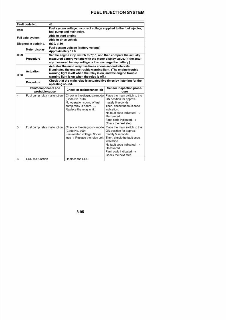
8/21/2019 Fz8 - Service Manual
http://slidepdf.com/reader/full/fz8-service-manual 490/609
Fail-safe systemU de ce a co d o s
Under certain conditions
Diagnostic code No. d:60
Meter display
EEPROM fault code display• 00 (no history)• 01–04: Cylinder fault code number (history exists)
If more than one cylinder is defective, the display switches every
two seconds to show the cylinder fault code numbers of all defec-tive cylinders in a repeating cycle.
Procedure —
Item/components andprobable cause
Check or maintenance jobSensor inspection proce-
dure
1 Locate the malfunction. Diagnostic mode (Code No.d60)00 indication: Check number6.01 indication: Check number2.02 indication: Check number3.03 indication: Check number4.04 indication: Check number5.
—
2 “01” is indicated in Diagnostic
mode (Code No. d60)EEPROM data error foradjustment of CO concentra-tion of cylinder #1
Change the CO concentra-
tion of cylinder #1, andrewrite in EEPROM.Refer to “ADJUSTING THEEXHAUST GAS VOLUME”on page 3-11.After this adjustment is made,the memory is not recoveredwhen the main switch isturned OFF and ON again. → Replace the ECU.
Place the main switch to the
ON position.Then, check the fault codeindication.No fault code indicated. → Recovered.Fault code indicated. → Return to Step 1 to carry outthe check again. If the condi-tion persists, proceed to Step6.
FUEL INJECTION SYSTEM
Fault code No. 44
ItemEEPROM cylinder fault code number: an error is detected whilereading or writing on EEPROM (CO adjustment value).
Fail-safe systemUnder certain conditions
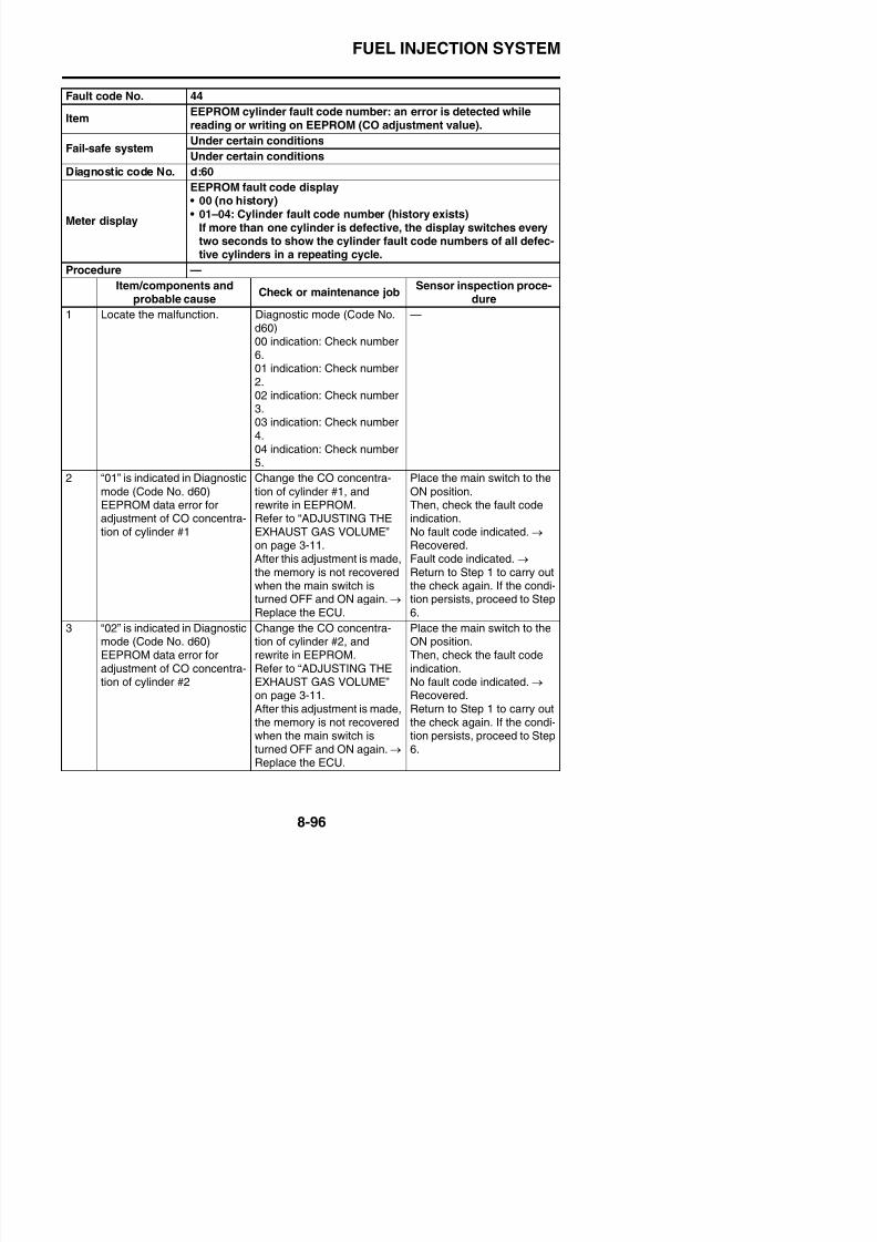
8/21/2019 Fz8 - Service Manual
http://slidepdf.com/reader/full/fz8-service-manual 491/609
4 “03” is indicated in Diagnosticmode (Code No. d60)EEPROM data error for
adjustment of CO concentra-tion of cylinder #3
Change the CO concentra-tion of cylinder #3, andrewrite in EEPROM.
Refer to “ADJUSTING THEEXHAUST GAS VOLUME”on page 3-11.After this adjustment is made,the memory is not recovered
when the main switch isturned OFF and ON again. → Replace the ECU.
Place the main switch to theON position.Then, check the fault code
indication.No fault code indicated. → Recovered.Fault code indicated. → Return to Step 1 to carry out
the check again. If the condi-tion persists, proceed to Step6.
5 “04” is indicated in Diagnosticmode (Code No. d60)EEPROM data error foradjustment of CO concentra-
tion of cylinder #4
Change the CO concentra-tion of cylinder #4, andrewrite in EEPROM.Refer to “ADJUSTING THE
EXHAUST GAS VOLUME”on page 3-11.After this adjustment is made,the memory is not recovered
when the main switch isturned OFF and ON again. → Replace the ECU.
Place the main switch to theON position.Then, check the fault codeindication.
No fault code indicated. → Recovered.Fault code indicated. → Return to Step 1 to carry out
the check again. If the condi-tion persists, proceed to Step6.
6 ECU malfunction Replace the ECU
Fail-safe systemUnder certain conditions
Diagnostic code No. d:60
Meter display
EEPROM fault code display• 00 (no history)• 01–04: Cylinder fault code number (history exists)
If more than one cylinder is defective, the display switches every
two seconds to show the cylinder fault code numbers of all defec-tive cylinders in a repeating cycle.
Procedure —
Item/components andprobable cause
Check or maintenance jobSensor inspection proce-
dure
FUEL INJECTION SYSTEM
Fault code No. 46
Item Incorrect voltage is supplied to the ECU.
Fail-safe systemAble to start engine
Able to drive vehicle
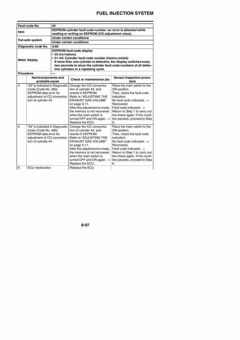
8/21/2019 Fz8 - Service Manual
http://slidepdf.com/reader/full/fz8-service-manual 492/609
Diagnostic code No. —
Meter display —
Procedure —
Item/components andprobable cause
Check or maintenance jobSensor inspection proce-
dure
1 Charging system malfunction Check the charging system.Refer to “CHARGING SYS-TEM” on page 8-19.Check the rectifier/regulator,AC magneto and wire har-ness. → Replace if defective.
Start and idle the engine forapproximately 5 seconds.Then, check the fault codeindication.No fault code indicated. → Recovered.Fault code indicated. → Recheck.
Fault code No. 47
ItemSub-throttle position sensor: open or short circuit detected. (no nor-mal signals are received from the sub-throttle position sensor.)
Fail-safe systemAble to start engine
Able to drive vehicle
Diagnostic code No. —
Meter display —
Procedure —
Item/components andprobable cause
Check or maintenance jobSensor inspection proce-
dure
1 Installation status of sub-throttle position sensor
Check the mounting sectionfor a loose or pinched mount-ing.
Place the main switch to theON position, and check thefault code indication.
No fault code indicated. →
Recovered.Fault code indicated. → Check the next step.
2 Connection of sub-throttlei i l
Poor connection → Connect itl i / l h
Place the main switch to theON i i d h k h
FUEL INJECTION SYSTEM
Fault code No. 47
ItemSub-throttle position sensor: open or short circuit detected. (no nor-mal signals are received from the sub-throttle position sensor.)
Fail-safe systemAble to start engine
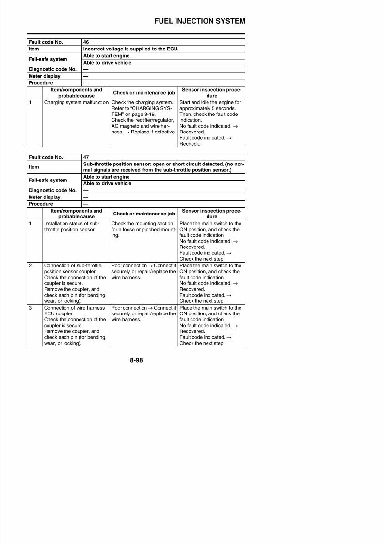
8/21/2019 Fz8 - Service Manual
http://slidepdf.com/reader/full/fz8-service-manual 493/609
TIP
If fault codes 47 and 48 are indicated simultaneously, take the actions specified for fault code 47first.
4 Continuity of wire harness Open or short circuit → Replace the wire harnessBlack/blue–Black/blueGreen/yellow–Green/yellowBlue–Blue
Place the main switch to theON position, and check thefault code indication.No fault code indicated. → Recovered.Fault code indicated. → Check the next step.
5 Sub-throttle position sensormalfunction
Check the sub-throttle posi-tion sensor.Refer to “CHECKING THESUB-THROTTLE POSITIONSENSOR” on page 8-199.Sub-throttle position sensormalfunction → Replace thesub-throttle position sensor.
Place the main switch to theON position, and check thefault code indication.No fault code indicated. → Recovered.Fault code indicated. → Check the next step.
6 ECU malfunction Replace the ECU.
Fail safe systemAble to drive vehicle
Diagnostic code No. —
Meter display —
Procedure —
Item/components andprobable cause
Check or maintenance jobSensor inspection proce-
dure
FUEL INJECTION SYSTEM
Fault code No. 48
ItemSub-throttle servo motor: stuck sub-throttle servo motor detected.signal from sub-throttle position sensor will not change. (sub-throt-
tle servo motor will not start.)
Abl t t t i
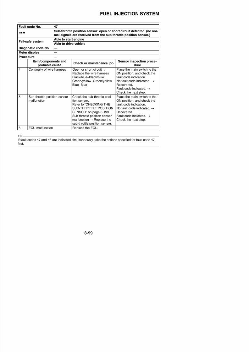
8/21/2019 Fz8 - Service Manual
http://slidepdf.com/reader/full/fz8-service-manual 494/609
Fail-safe systemAble to start engine
Able to drive vehicle
Diagnostic code No. d:56
Actuation
Sub-throttle valve will close and stops at standard position afterfully opened.This operation takes about 3 seconds and engine trouble warning
light will be turning on during operation.Procedure Check the operating sound of the sub-throttle servo motor.
Item/components andprobable cause
Check or maintenance jobSensor inspection proce-
dure
1 Installation status of sub-throttle position sensor
Check the mounting sectionfor a loose or pinched mount-ing.
Place the main switch to theON position, and check thefault code indication.No fault code indicated. →
Recovered.Fault code indicated. → Check the next step.
2 Connection of sub-throttleposition sensor couplerCheck the connection of thecoupler is secure.Remove the coupler, andcheck each pin (for bending,wear, or locking).
Check in the diagnostic code(Code No. d55). Check thesub-throttle servo motor forproper operation.
Poor connection → Connect itsecurely, or repair/replace thewire harness.
Place the main switch to theON position, and check thefault code indication.No fault code indicated. → Recovered.Fault code indicated. → Check the next step.
3 Connection of wire harness
ECU couplerCheck the connection of the
coupler is secure.Remove the coupler, andcheck each pin (for bending
Poor connection → Connect it
securely, or repair/replace thewire harness.
Place the main switch to the
ON position, and check thefault code indication.
No fault code indicated. → Recovered.Fault code indicated →
FUEL INJECTION SYSTEM
Fault code No. 48
ItemSub-throttle servo motor: stuck sub-throttle servo motor detected.signal from sub-throttle position sensor will not change. (sub-throt-
tle servo motor will not start.)Able to start engine
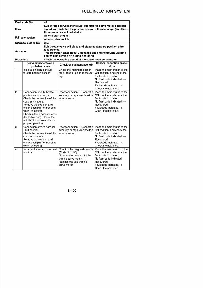
8/21/2019 Fz8 - Service Manual
http://slidepdf.com/reader/full/fz8-service-manual 495/609
TIP
If fault codes 47 and 48 are indicated simultaneously, take the actions specified for fault code 47first.
5 Continuity of wire harness Open or short circuit → Replace the wire harnessYellow/red–Yellow/redYellow/white–Yellow/white
Gray/black–Gray/blackGray/white–Gray/white
Place the main switch to theON position, and check thefault code indication.No fault code indicated. →
Recovered.Fault code indicated. → Check the next step.
6 ECU malfunction Replace the ECU.
Fault code No. 50
ItemFaulty ECU memory. (When this malfunction is detected in the ECU,the fault code number might not appear on the meter.)
Fail-safe systemUnable to start engine
Unable to drive vehicle
Diagnostic code No. —
Meter display —Procedure —
Item/components andprobable cause
Check or maintenance jobSensor inspection proce-
dure
Fail-safe systemAble to start engine
Able to drive vehicle
Diagnostic code No. d:56
Actuation
Sub-throttle valve will close and stops at standard position afterfully opened.This operation takes about 3 seconds and engine trouble warning
light will be turning on during operation.Procedure Check the operating sound of the sub-throttle servo motor.
Item/components andprobable cause
Check or maintenance jobSensor inspection proce-
dure
FUEL INJECTION SYSTEM
Fault code No. 70
ItemEngine idling stop: engine has been left idling. (The ECU automati-cally stops the engine after 20 minutes if it is left idling.)
Fail-safe systemAble to start engine
Able to dri e ehicle
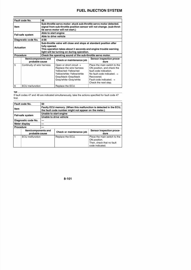
8/21/2019 Fz8 - Service Manual
http://slidepdf.com/reader/full/fz8-service-manual 496/609
yAble to drive vehicle
Diagnostic code No. —
Meter display —
Procedure —
Item/components andprobable cause
Check or maintenance jobSensor inspection proce-
dure
Engine idling stop
Fault code No. Er-1
ItemECU internal malfunction (output signal error): no signals arereceived from the ECU.
Fail-safe systemAble to start engine (Unable if ECU Failure)
Able to drive vehicle (Unable if ECU Failure)
Diagnostic code No. —
Meter display —
Procedure —
Item/components andprobable cause
Check or maintenance jobSensor inspection proce-
dure
1 Connection of meter couplerCheck the connection of the
coupler is secure.Remove the coupler, andcheck each pin (for bending,wear, or locking).
Poor connection → Connect itsecurely, or repair/replace the
wire harness.
Place the main switch to theON position, and check the
fault code indication.No fault code indicated. → Recovered.Fault code indicated. → Check the next step.
2 Connection of wire harnessECU couplerCheck the connection of the
coupler is secure.Remove the coupler, andcheck each pin (for bending,wear, or locking).
Poor connection → Connect itsecurely, or repair/replace thewire harness.
Place the main switch to theON position, and check thefault code indication.
No fault code indicated. → Recovered.Fault code indicated. → Check the next step.
FUEL INJECTION SYSTEM
Fault code No. Er-1
ItemECU internal malfunction (output signal error): no signals arereceived from the ECU.
Fail-safe systemAble to start engine (Unable if ECU Failure)
Able to drive vehicle (Unable if ECU Failure)
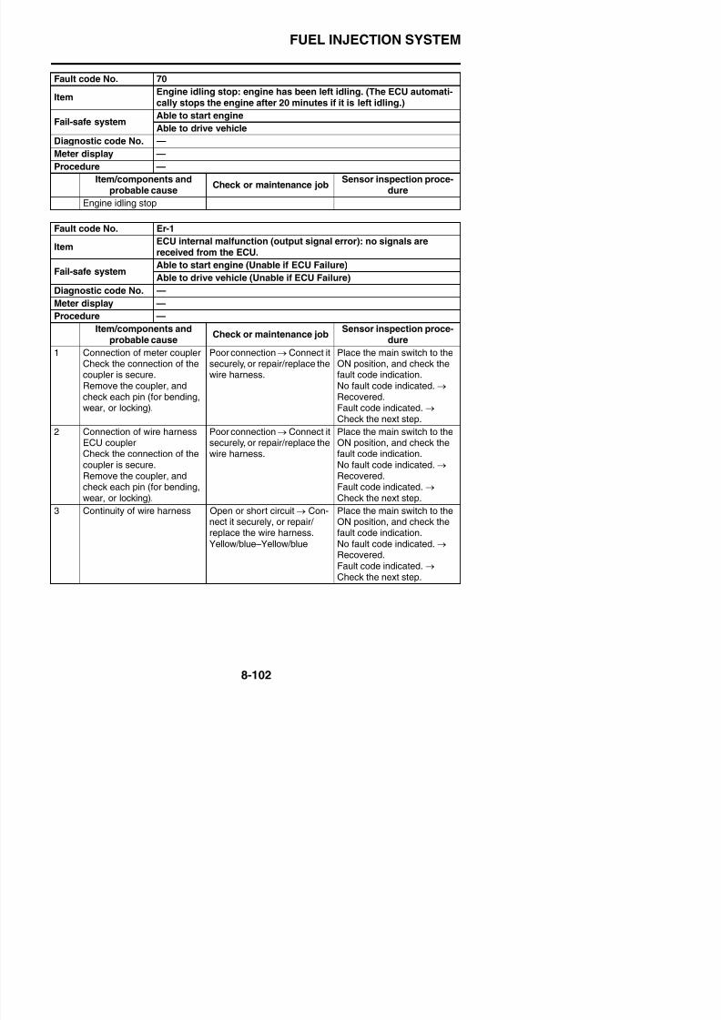
8/21/2019 Fz8 - Service Manual
http://slidepdf.com/reader/full/fz8-service-manual 497/609
4 Abnormal meter unit opera-tion
Replace the meter unit. Place the main switch to theON position, and check thefault code indication.No fault code indicated. → Recovered.Fault code indicated. → Check the next step.
5 ECU malfunction Replace the ECU
Fault code No. Er-2
ItemECU internal malfunction (output signal error): no signals arereceived from the ECU within the specified duration.
Fail-safe systemAble to start engine
Able to drive vehicle
Diagnostic code No. —
Meter display —
Procedure —
Item/components andprobable cause
Check or maintenance jobSensor inspection proce-
dure
1 Connection of meter couplerCheck the connection of thecoupler is secure.
Remove the coupler, andcheck each pin (for bending,wear, or locking).
Poor connection → Connect itsecurely, or repair/replace thewire harness.
Place the main switch to theON position, and check thefault code indication.
No fault code indicated.→
Recovered.Fault code indicated. → Check the next step.
2 C ti f i h P ti C t it Pl th i it h t th
Able to drive vehicle (Unable if ECU Failure)
Diagnostic code No. —
Meter display —
Procedure —
Item/components andprobable cause
Check or maintenance jobSensor inspection proce-
dure
FUEL INJECTION SYSTEM
Fault code No. Er-2
ItemECU internal malfunction (output signal error): no signals arereceived from the ECU within the specified duration.
Fail-safe systemAble to start engine
Able to drive vehicle
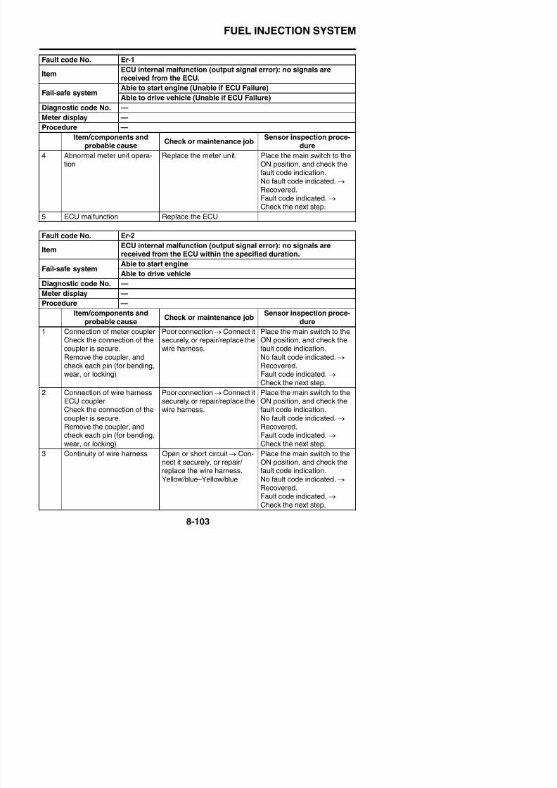
8/21/2019 Fz8 - Service Manual
http://slidepdf.com/reader/full/fz8-service-manual 498/609
4 Abnormal meter unit opera-tion
Replace the meter unit. Place the main switch to theON position, and check thefault code indication.No fault code indicated. → Recovered.Fault code indicated. → Check the next step.
5 ECU malfunction Replace the ECU.
Fault code No. Er-3
ItemECU internal malfunction (output signal error): data from the ECUcannot be received correctly.
Fail-safe systemAble to start engine
Able to drive vehicle
Diagnostic code No. —
Meter display —Procedure —
Item/components andprobable cause
Check or maintenance jobSensor inspection proce-
dure
1 Connection of meter couplerCheck the connection of thecoupler is secure.
Remove the coupler, andcheck each pin (for bending,wear, or locking).
Poor connection → Connect itsecurely, or repair/replace thewire harness.
Place the main switch to theON position, and check thefault code indication.
No fault code indicated.→
Recovered.Fault code indicated. → Check the next step.
2 C ti f i h P ti C t it Pl th i it h t th
Able to drive vehicle
Diagnostic code No. —
Meter display —
Procedure —
Item/components andprobable cause
Check or maintenance jobSensor inspection proce-
dure
FUEL INJECTION SYSTEM
Fault code No. Er-3
ItemECU internal malfunction (output signal error): data from the ECUcannot be received correctly.
Fail-safe systemAble to start engine
Able to drive vehicle
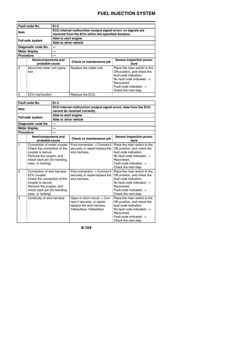
8/21/2019 Fz8 - Service Manual
http://slidepdf.com/reader/full/fz8-service-manual 499/609
4 Abnormal meter unit opera-tion
Replace the meter unit. Place the main switch to theON position, and check thefault code indication.No fault code indicated. → Recovered.Fault code indicated. → Check the next step.
5 ECU malfunction Replace the ECU.
Fault code No. Er-4
ItemECU internal malfunction (input signal error): non-registered datahas been received from the meter.
Fail-safe systemAble to start engine
Able to drive vehicle
Diagnostic code No. —
Meter display —Procedure —
Item/components andprobable cause
Check or maintenance jobSensor inspection proce-
dure
1 Connection of meter couplerCheck the connection of thecoupler is secure.
Remove the coupler, andcheck each pin (for bending,wear, or locking).
Poor connection → Connect itsecurely, or repair/replace thewire harness.
Place the main switch to theON position, and check thefault code indication.
No fault code indicated.→
Recovered.Fault code indicated. → Check the next step.
2 C ti f i h P ti C t it Pl th i it h t th
Diagnostic code No. —
Meter display —
Procedure —
Item/components andprobable cause
Check or maintenance jobSensor inspection proce-
dure
FUEL INJECTION SYSTEM
Fault code No. Er-4
ItemECU internal malfunction (input signal error): non-registered datahas been received from the meter.
Fail-safe systemAble to start engineAble to drive vehicle

8/21/2019 Fz8 - Service Manual
http://slidepdf.com/reader/full/fz8-service-manual 500/609
4 Abnormal meter unit opera-tion
Replace the meter unit. Place the main switch to theON position, and check thefault code indication.No fault code indicated. → Recovered.Fault code indicated. → Check the next step.
5 ECU malfunction Replace the ECU.
Diagnostic code No. —
Meter display —
Procedure —
Item/components andprobable cause
Check or maintenance jobSensor inspection proce-
dure
FUEL INJECTION SYSTEM
EAS30660
DIAGNOSTIC CODE TABLE
TIP
The following tables contain information about diagnostic code numbers that do not have a corre-sponding fault code number. (These items are not listed in “TROUBLESHOOTING DETAILS”.)
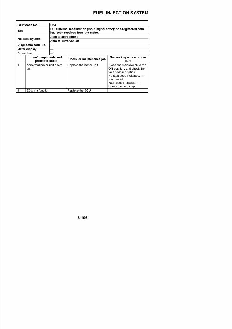
8/21/2019 Fz8 - Service Manual
http://slidepdf.com/reader/full/fz8-service-manual 501/609
Diag-nosticcodeNo.
Item Meter display/Actuation Procedure
d:48 Air induction system sole-
noid
Actuates the air induction
system solenoid five times atone-second intervals.Illuminates the engine trou-ble warning light.
Check the operating sound
of the air induction systemsolenoid five times.
d:51 Radiator fan motor relay Actuates the radiator fanmotor relay for five cycles offive seconds. (ON 2 sec-
onds, OFF 3 seconds)
Illuminates the engine trou-ble warning light.
Check the operating soundof the radiator fan motorrelay five times.
d:52 Headlight relay Actuates the headlight relayfor five cycles of five seconds.(ON 2 seconds, OFF 3 sec-onds)Illuminates the engine trou-ble warning light.
Check the operating soundof the headlight relay fivetimes.
d:61 Malfunction history codedisplay
—
• No history 00
• History exists Fault code Nos. d11–70• (If more than one code
number is detected, the dis-play alternates every twoseconds to show all thedetected code numbers.When all code numbers areshown, the display repeatsthe same process )
FUEL INJECTION SYSTEM
d:63 Malfunction code reinstate-ment (for fault code No d24
Diag-nosticcode
No.
Item Meter display/Actuation Procedure
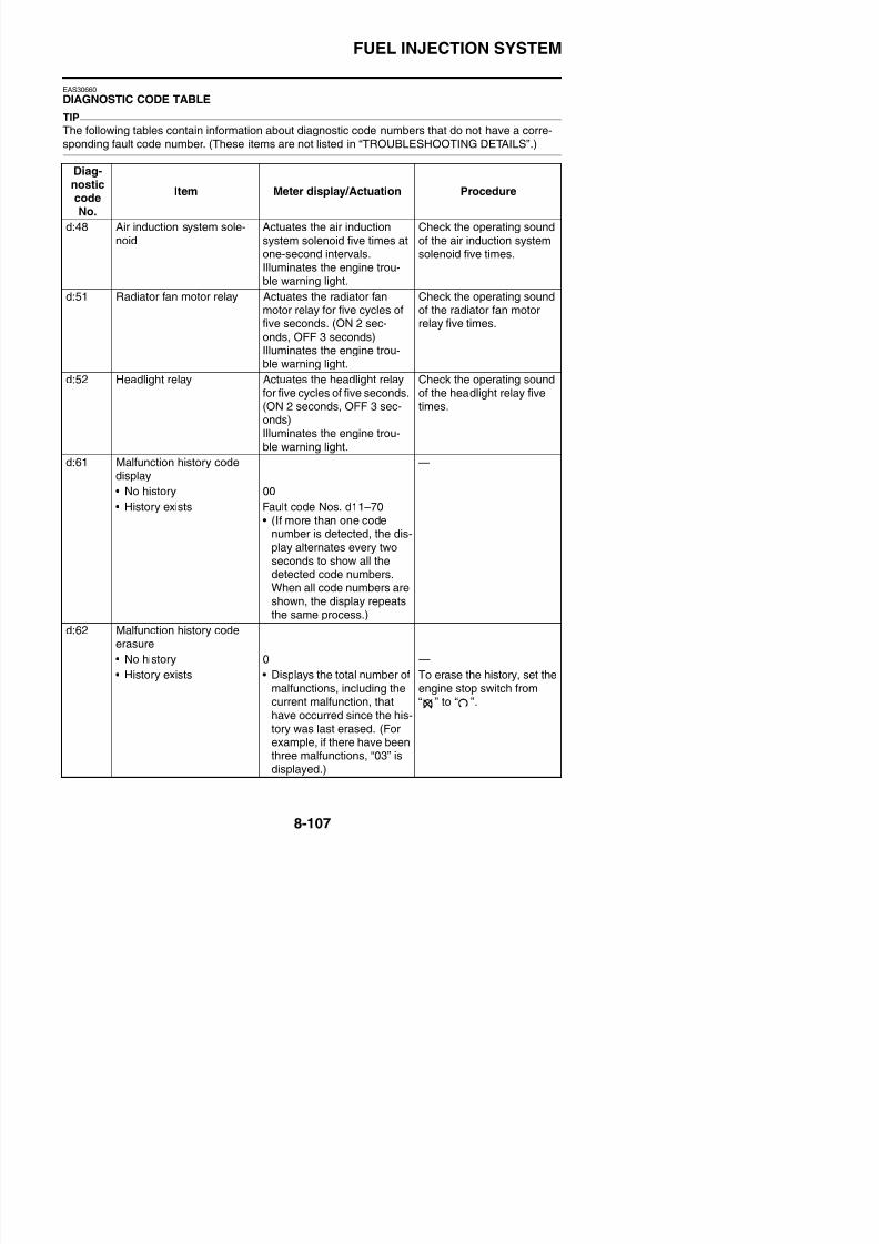
8/21/2019 Fz8 - Service Manual
http://slidepdf.com/reader/full/fz8-service-manual 502/609
Set the main switch to “OFF” to cancel the diagnostic mode.
TIP
Information about each diagnostic code No. is organized in this manual as follows:• If a diagnostic code No. has a corresponding fault code No., the information is shown in TROU-
BLESHOOTING DETAILS. (Refer to “TROUBLESHOOTING DETAILS” on page 8-55)• If a diagnostic code No. does not have a corresponding fault code No., the information is shown in
DIAGNOSTIC CODE TABLE. (Refer to “DIAGNOSTIC CODE TABLE” on page 8-107)
ment (for fault code No. d24only)
• No malfunction code 00 —
• Malfunction code exists Fault code No. d24• (If more than one code
number is detected, the dis-
play alternates every twoseconds to show all thedetected code numbers.When all code numbers are
shown, the display repeatsthe same process.)
To reinstate, set the enginestop switch from “ ” to
“ ”.
d:70 Control number 0–254 [-] —
FUEL PUMP SYSTEM
EAS27550
FUEL PUMP SYSTEM
EAS27560
CIRCUIT DIAGRAM
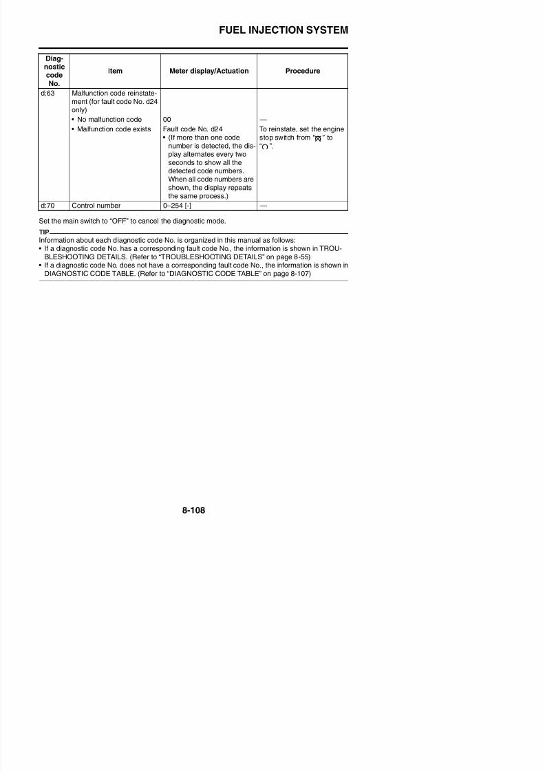
8/21/2019 Fz8 - Service Manual
http://slidepdf.com/reader/full/fz8-service-manual 503/609
FUEL PUMP SYSTEM
FZ8NA1. Main switch
6. Main fuse
7. Frame ground
8. Engine ground
9. Battery
10 N ti b tt d l d

8/21/2019 Fz8 - Service Manual
http://slidepdf.com/reader/full/fz8-service-manual 504/609
10.Negative battery ground lead
11.Fuel injection system fuse
14.Relay unit
16.Fuel pump relay
19.Fuel pump
25.ECU (engine control unit)
56.Right handlebar switch
58.Engine stop switch
85.Ignition fuse
FUEL PUMP SYSTEM

8/21/2019 Fz8 - Service Manual
http://slidepdf.com/reader/full/fz8-service-manual 505/609
FUEL PUMP SYSTEM
FZ8SA1. Main switch
6. Main fuse
7. Frame ground
8. Engine ground
9. Battery
10 Negative battery ground lead

8/21/2019 Fz8 - Service Manual
http://slidepdf.com/reader/full/fz8-service-manual 506/609
10.Negative battery ground lead
11.Fuel injection system fuse
14.Relay unit
16.Fuel pump relay
19.Fuel pump
25.ECU (engine control unit)
56.Right handlebar switch
58.Engine stop switch
86.Ignition fuse
FUEL PUMP SYSTEM
EAS27570
TROUBLESHOOTINGIf the fuel pump fails to operate.
TIP
• Before troubleshooting, remove the following part(s):1. Rider seat2 Passenger seat
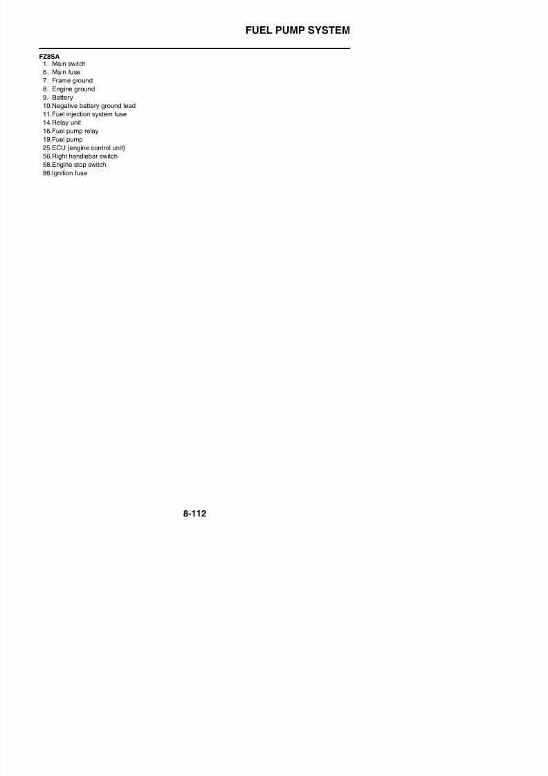
8/21/2019 Fz8 - Service Manual
http://slidepdf.com/reader/full/fz8-service-manual 507/609
2. Passenger seat
3. Left inner panel (FZ8SA)4. Right inner panel (FZ8SA)5. Left side panel (FZ8SA)6. Right side panel (FZ8SA)7. Front cowling (FZ8SA)8. Fuel tank9. Air filter case
NG→
OK↓
NG→
OK↓
NG→
OK↓
NG→
OK↓
1. Check the fuses.(Main, ignition and fuel injectionsystem)Refer to “CHECKING THE FUSES”
on page 8-185.
Replace the fuse(s).
2. Check the battery.Refer to “CHECKING AND
CHARGING THE BATTERY” onpage 8-186.
• Clean the battery terminals.
• Recharge or replace the battery.
3. Check the main switch.
Refer to “CHECKING THESWITCHES” on page 8-179.
Replace the main switch/immobilizerunit.
4. Check the engine stop switch.
Refer to “CHECKING THESWITCHES” on page 8-179.
Replace the right handlebar switch.
FUEL PUMP SYSTEM
NG→
OK↓
7. Check the entire fuel pump sys-tem’s wiring.Refer to “CIRCUIT DIAGRAM” on
page 8-109.
Properly connect or repair the fuelpump system’s wiring.
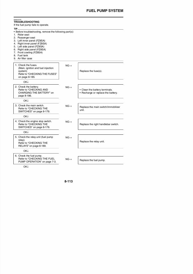
8/21/2019 Fz8 - Service Manual
http://slidepdf.com/reader/full/fz8-service-manual 508/609
Replace the ECU.
IMMOBILIZER SYSTEM
EAS27640
IMMOBILIZER SYSTEM
EAS27650
CIRCUIT DIAGRAM
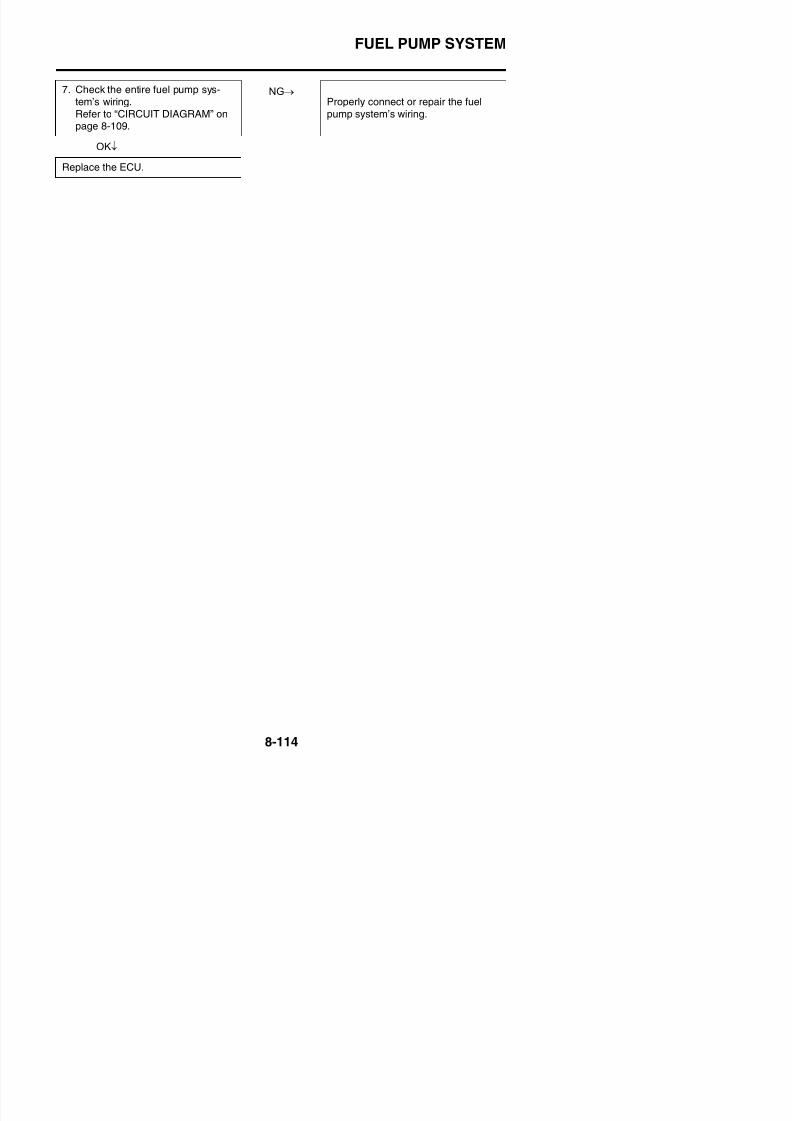
8/21/2019 Fz8 - Service Manual
http://slidepdf.com/reader/full/fz8-service-manual 509/609
IMMOBILIZER SYSTEM
FZ8NA1. Main switch
4. Backup fuse
5. Immobilizer unit
6. Main fuse
7. Frame ground
8. Engine ground

8/21/2019 Fz8 - Service Manual
http://slidepdf.com/reader/full/fz8-service-manual 510/609
9. Battery
10.Negative battery ground lead
25.ECU (engine control unit)
43.Meter assembly
44.Immobilizer system indicator light
48.Multi-function meter85.Ignition fuse
IMMOBILIZER SYSTEM
8/21/2019 Fz8 - Service Manual
http://slidepdf.com/reader/full/fz8-service-manual 511/609
IMMOBILIZER SYSTEM
FZ8SA1. Main switch
4. Backup fuse
5. Immobilizer unit
6. Main fuse7. Frame ground
8. Engine ground
9 B
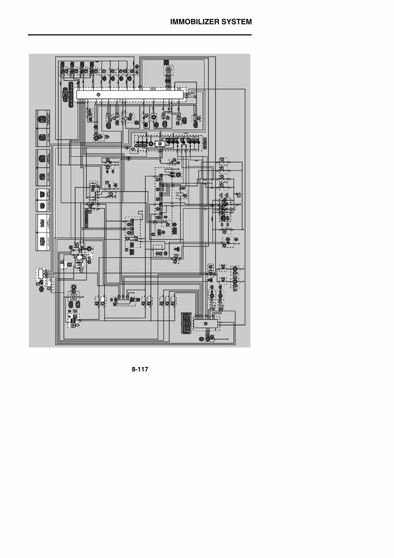
8/21/2019 Fz8 - Service Manual
http://slidepdf.com/reader/full/fz8-service-manual 512/609
9. Battery
10.Negative battery ground lead
25.ECU (engine control unit)
43.Meter assembly
44.Immobilizer system indicator light
48.Multi-function meter86.Ignition fuse
IMMOBILIZER SYSTEM
EAS27671
GENERAL INFORMATIONThis vehicle is equipped with an immobilizer system to help prevent theft by re-registering codes inthe standard keys. This system consists of the following:
• A code re-registering key (with a red bow)• Two standard keys (with a black bow) that can be re-registered with new codes• A transponder (installed in the red key bow)• An immobilizer unit

8/21/2019 Fz8 - Service Manual
http://slidepdf.com/reader/full/fz8-service-manual 513/609
• An immobilizer unit
• The ECU• An immobilizer system indicator lightThe key with the red bow is used to register codes in each standard key. Do not use the key with thered bow for driving. It should only be used for re-registering new codes in the standard keys. The
immobilizer system cannot be operated with a new key until the key registered with a code. If youlose the code re-registering key, the ECU and main switch (equipped with the immobilizer unit) needto be replaced.Therefore, always use a standard key for driving. (See caution below.)
TIP
Each standard key is registered during production, therefore re-registering at purchase is not neces-sary.
ECA14971
• DO NOT LOSE THE CODE RE-REGISTERING KEY! If the code re-registering key is lost, reg-istering new codes in the standard keys is impossible. The standard keys can still be usedto start the vehicle. However, if code re-registering is required (e.g., if a new standard key ismade or all keys are lost) the entire immobilizer system must be replaced. Therefore, it ishighly recommended to use either standard key for driving, and to keep the code re-regis-tering key in a safe place.
• Do not submerse the keys in water.• Do not expose the keys to excessively high temperatures.• Do not place the keys close to magnets (this includes, but is not limited to, products such
as speakers, etc.).• Do not place heavy items on the keys.• Do not grind the keys or alter their shape.• Do not disassemble the key bows.• Do not put two keys of any immobilizer system on the same key ring.
• Keep the standard keys as well as other immobilizer system keys away from the code re-registering key.
• Keep other immobilizer system keys away from the main switch as they may cause signalinterference.
IMMOBILIZER SYSTEM
EAS27691
PART REPLACEMENT AND KEY CODE REGISTRATION REQUIREMENTSIn the course of use, you may encounter the following cases where replacement of parts and regis-tration of code re-registering/standard keys are required.
TIP
Each standard key is registered during production, therefore re-registering at purchase is not neces-sary.
8/21/2019 Fz8 - Service Manual
http://slidepdf.com/reader/full/fz8-service-manual 514/609
* Accessory locks mean the seat lock and fuel tank cap.
Code re-registering key registration:When the immobilizer unit or ECU is replaced, the code re-registering key must be registered to theunit.To register a code re-registering key:
1. Turn the main switch to “ON” with the code re-registering key.
TIP
Check that the immobilizer system indicator light comes on for one second, then goes off. When thei bili t i di t li ht ff th d i t i k h b i t d
Parts to be replaced
Key registrationrequirement
Main switch/ immobilizer unit Standard
keyECU
Acces-sory lock*
and keyMainswitch Immobi-lizer unit
Standard key is lost √ New standard key
All keys have beenlost (including codere-registering key)
√ √ √ √Code re-registeringkey and standardkeys
ECU is defective √Code re-registeringkey and standard
keys
Immobilizer unit isdefective
√Code re-registeringkey and standardkeys
Main switch is defec-tive
√ √ √ √Code re-registeringkey and standardkeys
Accessory lock* isdefective √ Not required
IMMOBILIZER SYSTEM
Standby mode:To enable the immobilizer system, turn the ignition key to “OFF”. 30 seconds later, the indicator lightwill start flashing continuously in the standby flashing mode pattern for up to 24 hours. After thattime, the indicator light will stop flashing, but the immobilizer system is still enabled.Standby mode
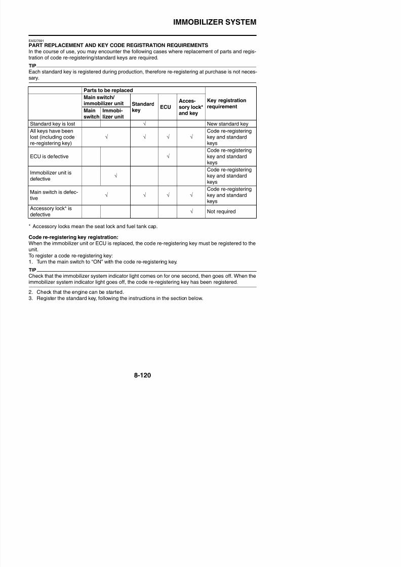
8/21/2019 Fz8 - Service Manual
http://slidepdf.com/reader/full/fz8-service-manual 515/609
Standard key registration:Standard key registration is required when a standard key is lost and needs to be replaced, or whenthe code re-registering key is re-registered after the immobilizer unit or ECU are replaced.
TIP
Do not start the engine with a standard key that has not been registered. If the main switch is turned“ON” with a standard key that has not been registered, the immobilizer system indicator light flashesto indicate fault code “52”. (Refer to “SELF-DIAGNOSIS FAULT CODE INDICATION” on page 8-124).
1. Check that the immobilizer system indicator light signals the standby mode.2. Using the code re-registering key, turn the main switch to “ON”, then “OFF”, and then remove the
key within 5 seconds.3. Insert the first standard key to be registered into the main switch, then turn the key to “ON” within
5 seconds to activate the key registration mode.
TIP
The existing standard key code is erased from the memory when the key registration mode is acti-
vated. When the key registration mode is activated, the immobilizer system indicator light flashesrapidly.
4. While the indicator light is flashing, turn the main switch to “OFF”, remove the key, and within 5
a. Main switch “ON”
b. Main switch “OFF”
c. LED on
d. LED off
e. Standby mode on
f. Standby mode off
IMMOBILIZER SYSTEM
Standard key registration
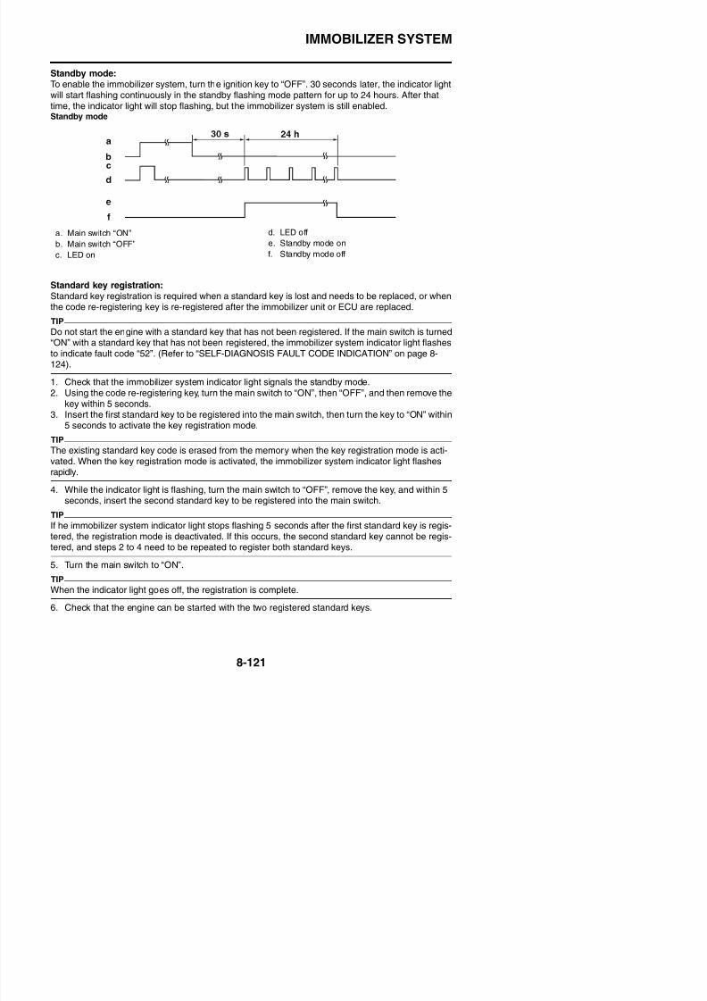
8/21/2019 Fz8 - Service Manual
http://slidepdf.com/reader/full/fz8-service-manual 516/609
Voiding the standard key code:If a standard key has been lost, it is possible to disable its use by re-registering the remaining stan-dard key. Standard key registration erases the stored standard key code from the memory, thus dis-abling the lost standard key. To re-register, refer to “Standard key registration”.Standard key code voiding method
a. Main switch “ON”
b. Main switch “OFF”
c. LED on
d. LED off
e. Less than 5.0 s
f. Code re-registering key
g. First standard key
h. Second standard key
i. Registration mode
A. Registration of the second standard key iscomplete.
B. Immobilizer system indicator light stopsflashing when the registration of the secondstandard key is complete.
a. Main switch “ON”
b. Main switch “OFF”
c. LED on
d. LED off
e. Less than 5.0 s
IMMOBILIZER SYSTEM
EAS27701
TROUBLESHOOTINGWhen the main switch is turned to “ON”, the immobilizer system indicator light does not come on norflashes.
NG→1. Check the fuses.(Main, ignition, and backup)Refer to “CHECKING THE FUSES”on page 8 185
Replace the fuse(s).
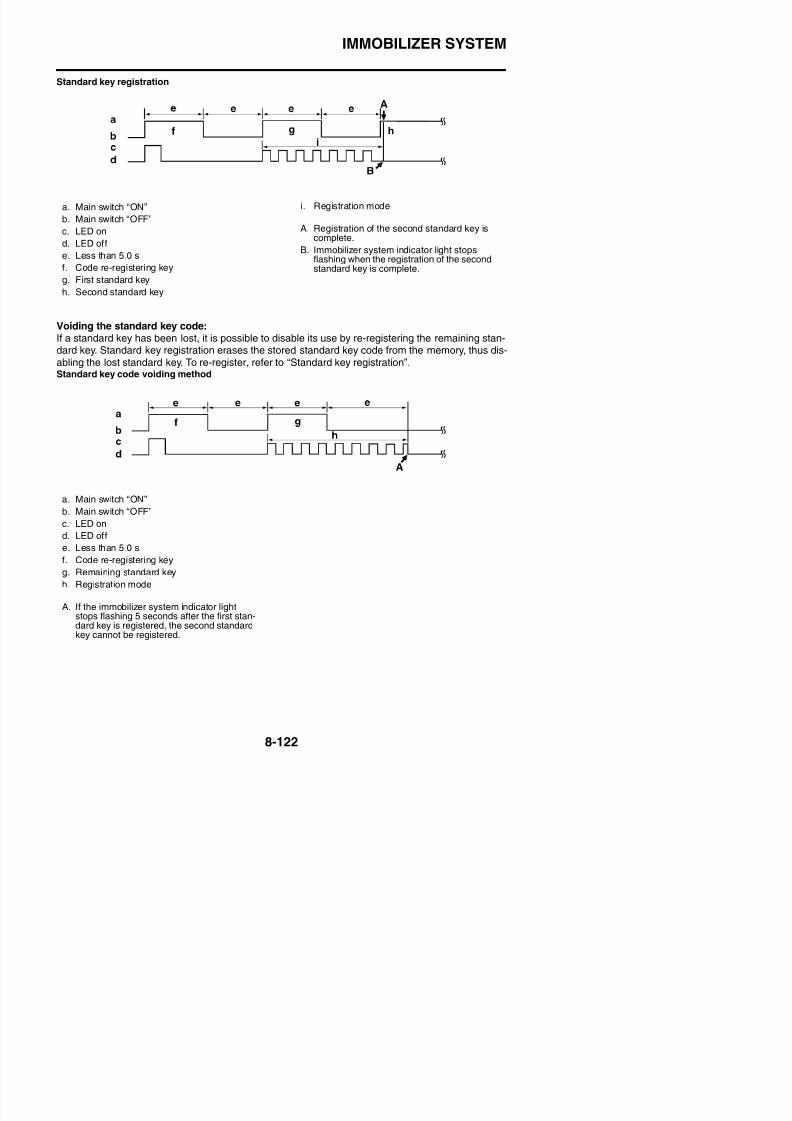
8/21/2019 Fz8 - Service Manual
http://slidepdf.com/reader/full/fz8-service-manual 517/609
OK↓
NG→
OK↓
NG→
OK↓
NG→
OK↓
on page 8-185.
2. Check the battery.
Refer to “CHECKING ANDCHARGING THE BATTERY” onpage 8-186.
• Clean the battery terminals.• Recharge or replace the battery.
3. Check the main switch.Refer to “CHECKING THESWITCHES” on page 8-179.
Replace the main switch/immobilizerunit.
4. Check the entire immobilizer sys-tem wiring.Refer to “CIRCUIT DIAGRAM” onpage 8-115.
Properly connect or repair the immobi-lizer system wiring.
• Check the condition of the eachimmobilizer system circuits.
• Refer to “SELF-DIAGNOSIS FAULTCODE INDICATION” on page 8-124.
IMMOBILIZER SYSTEM
EAS27721
SELF-DIAGNOSIS FAULT CODE INDICATIONWhen a system failure occurs, the error code number is indicated in the LCD display of meter andthe immobilizer system indicator light blinks at the same time. The pattern of blinking also shows the
error code.Faultcode
Part Symptom Cause Action
51 IMMOBILIZER Code cannot be 1 Radio wave interfer- 1 Keep magnets
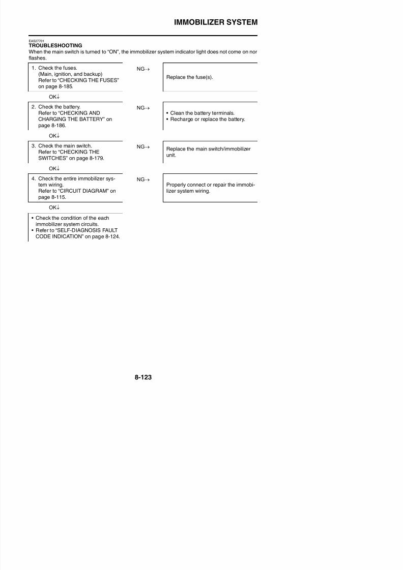
8/21/2019 Fz8 - Service Manual
http://slidepdf.com/reader/full/fz8-service-manual 518/609
51 IMMOBILIZERUNIT
Code cannot betransmitted betweenthe key and immobi-lizer unit.
1. Radio wave interfer-ence caused byobjects around thekeys and antennas.
2. Immobilizer unit mal-function.
3. Key malfunction.
1. Keep magnets,metal objects,and other immo-bilizer systemkeys away formthe keys andantennas.
2. Replace themain switch/ immobilizer unit.
3. Replace the key.
52 IMMOBILIZERUNIT
Codes between thekey and immobilizerunit do not match.
1. Signal received fromother transponder(failed to recognizecode after ten con-secutive attempts).
2. Signal received fromunregistered stan-dard key.
1. Place the immo-bilizer unit atleast 50 mmaway from thetransponder ofother vehicles.
2. Register thestandard key.
53 IMMOBILIZER
UNIT
Codes cannot be
transmitted betweenthe ECU and theimmobilizer unit.
Noise interference or dis-
connected lead/cable.1. Interference due toradio wave noise.
2. Disconnected com-munication harness.
3. Immobilizer unit mal-function.
4. ECU malfunction.
1. Check the wire
harness and con-nector.2. Replace the
main switch/ immobilizer unit.
3. Replace theECU.
54 IMMOBILIZERUNIT
Codes transmittedbetween the ECUand the immobilizerunit do not match.
Noise interference or dis-connected lead/cable.1. Interference due to
radio wave noise.
1. Register thecode re-register-ing key.
2. Check the wire
IMMOBILIZER SYSTEM
55 IMMOBILIZER
UNIT
Key code registra-
tion malfunction.
Same standard key was
attempted to be regis-tered two consecutivetimes.
Register another
standard key.
56 ECU Undefinition code isi d
Noise interference or dis-t d l d/ bl
1. Check the wireh d
Faultcode
Part Symptom Cause Action
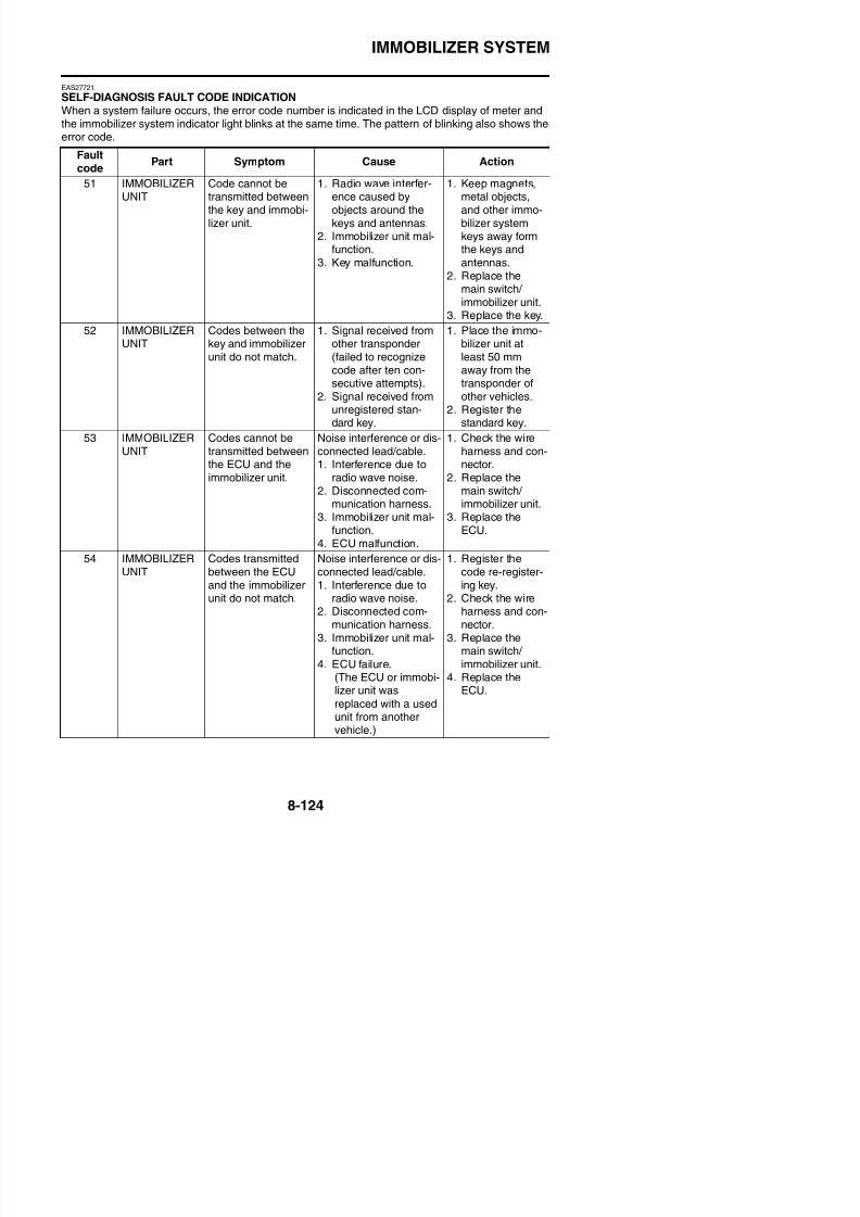
8/21/2019 Fz8 - Service Manual
http://slidepdf.com/reader/full/fz8-service-manual 519/609
Immobilizer system indicator light fault code indicationDigit of 10 : Cycles of 1 sec. ON and 1.5 sec. OFF.Digit of 1 : Cycles of 0.5 sec. ON and 0.5 sec. OFF.Example: fault code 52
received. connected lead/cable. harness and con-
nector.2. Replace the
main switch/
immobilizer unit.3. Replace the
ECU.
a. Light on
b. Light off
IMMOBILIZER SYSTEM
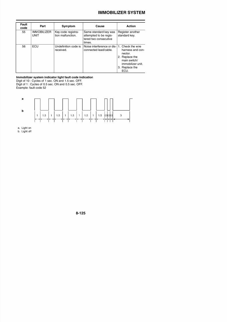
8/21/2019 Fz8 - Service Manual
http://slidepdf.com/reader/full/fz8-service-manual 520/609
ABS (ANTI-LOCK BRAKE SYSTEM)
EAS28790
ABS (ANTI-LOCK BRAKE SYSTEM)
EAS27730
CIRCUIT DIAGRAM

8/21/2019 Fz8 - Service Manual
http://slidepdf.com/reader/full/fz8-service-manual 521/609
ABS (ANTI-LOCK BRAKE SYSTEM)
FZ8NA1. Main switch
6. Main fuse
7. Frame ground
8. Engine ground9. Battery
10.Negative battery ground lead
14.Relay unit
15 Starting circuit cut off relay
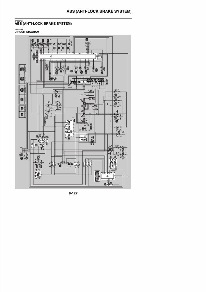
8/21/2019 Fz8 - Service Manual
http://slidepdf.com/reader/full/fz8-service-manual 522/609
15.Starting circuit cut-off relay
25.ECU (engine control unit)
43.Meter assembly
48.Multi-function meter
53.ABS warning light56.Right handlebar switch
57.Front brake light switch
58.Engine stop switch
59.Start switch
60.Rear brake light switch
77.Tail/brake light
85.Ignition fuse
87.Signal fuse89.ABS motor fuse
90.ABS solenoid fuse
91.ABS ECU fuse
92.ABS ECU (electronic control unit)
93.ABS test coupler
94.Front wheel sensor
95.Rear wheel sensor
ABS (ANTI-LOCK BRAKE SYSTEM)
8/21/2019 Fz8 - Service Manual
http://slidepdf.com/reader/full/fz8-service-manual 523/609
ABS (ANTI-LOCK BRAKE SYSTEM)
FZ8SA1. Main switch
6. Main fuse
7. Frame ground
8. Engine ground9. Battery
10.Negative battery ground lead
14.Relay unit
15 Starting circuit cut-off relay
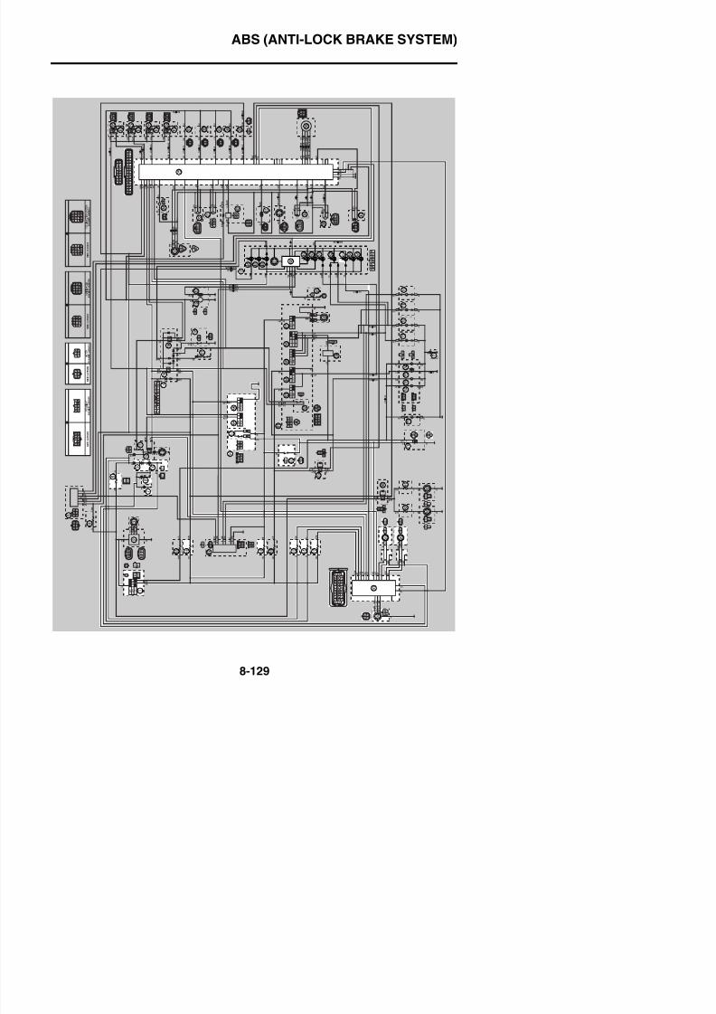
8/21/2019 Fz8 - Service Manual
http://slidepdf.com/reader/full/fz8-service-manual 524/609
15.Starting circuit cut off relay
25.ECU (engine control unit)
43.Meter assembly
48.Multi-function meter
53.ABS warning light56.Right handlebar switch
57.Front brake light switch
58.Engine stop switch
59.Start switch
60.Rear brake light switch
78.Tail/brake light
86.Ignition fuse
88.Signal fuse90.ABS motor fuse
91.ABS solenoid fuse
92.ABS ECU fuse
93.ABS ECU (electronic control unit)
94.ABS test coupler
95.Front wheel sensor
96.Rear wheel sensor
ABS (ANTI-LOCK BRAKE SYSTEM)
EAS27740
ABS COMPONENTS CHART

8/21/2019 Fz8 - Service Manual
http://slidepdf.com/reader/full/fz8-service-manual 525/609
ABS (ANTI-LOCK BRAKE SYSTEM)
1. Hydraulic unit assembly (ABS ECU)
2. ABS warning light
3. Rear wheel sensor rotor
4. Rear wheel sensor
5. Front wheel sensor
6. Front wheel sensor rotor
7. ABS test coupler
8. Fuse box 1
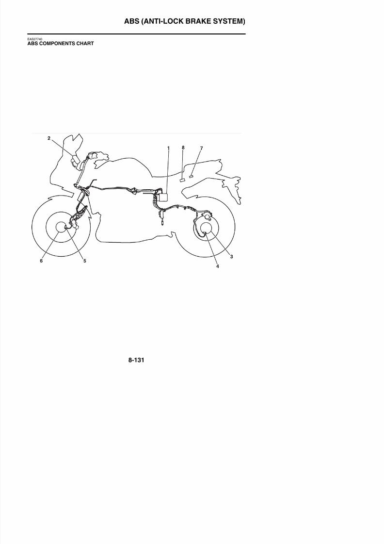
8/21/2019 Fz8 - Service Manual
http://slidepdf.com/reader/full/fz8-service-manual 526/609
ABS (ANTI-LOCK BRAKE SYSTEM)
EAS27750
ABS COUPLER LOCATION CHART
8/21/2019 Fz8 - Service Manual
http://slidepdf.com/reader/full/fz8-service-manual 527/609
ABS (ANTI-LOCK BRAKE SYSTEM)
1. Meter assembly coupler
2. Rear wheel sensor coupler
3. ABS test coupler
4. Front wheel sensor coupler
5. ABS ECU coupler
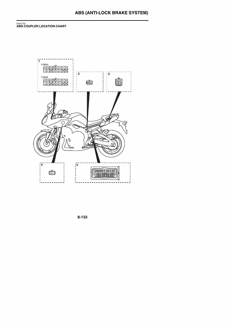
8/21/2019 Fz8 - Service Manual
http://slidepdf.com/reader/full/fz8-service-manual 528/609
ABS (ANTI-LOCK BRAKE SYSTEM)
EAS27770
MAINTENANCE OF THE ABS ECU
Checking the ABS ECU1. Check:
• Terminals “1” of the ABS ECUCracks/damages → Replace the hydraulic unit assembly and the brake pipes that are con-nected to the assembly as a set.
• Terminals “2” of the ABS ECU couplerConnection defective contaminated come-off → Correct or clean
8/21/2019 Fz8 - Service Manual
http://slidepdf.com/reader/full/fz8-service-manual 529/609
Connection defective, contaminated, come off → Correct or clean.
TIP
If the ABS ECU coupler is clogged with mud or dir t, clean with compressed air.
EAS27790
ABS TROUBLESHOOTING OUTLINEThis section describes the troubleshooting for the ABS in detail. Read this service manual carefullyand make sure you fully understand the information provided before repairing any malfunctions orperforming service.
The ABS ECU (electronic control unit) has a self-diagnosis function. When failures occur in the sys-tem, the ABS warning light on the meter assembly indicates a malfunction.The following troubleshooting describes the problem identification and service method according tothe indications by the multi-function display. For troubleshooting items other than the following items,follow the normal service method.
WARNING
EWA4B56006
When maintenance or checks have been performed on components related to the ABS, be
sure to perform a final check before delivering the vehicle to the customer. (Refer to “[D-3]FINAL CHECK” on page 8-174.)
ABS operation when the ABS warning light comes on
ABS (ANTI-LOCK BRAKE SYSTEM)
Self-diagnosis and servicingThe ABS ECU has a self-diagnosis function. By utilizing this function, quick problem identificationand service are possible. Previous malfunctions can be checked since the ABS ECU also stores themalfunction history.
The multi-function display indicates all the fault codes recorded in the ABS ECU.Note all of the indicated fault codes if more than two fault codes are stored in the memory. When theservice is finished, check the normal operation of the vehicle, and then delete the fault code(s).(Refer to “[D-3] FINAL CHECK” on page 8-174.) By deleting the fault codes stored in the ABS ECUmemory, it is possible to pursue the cause correctly if another malfunction occurs.
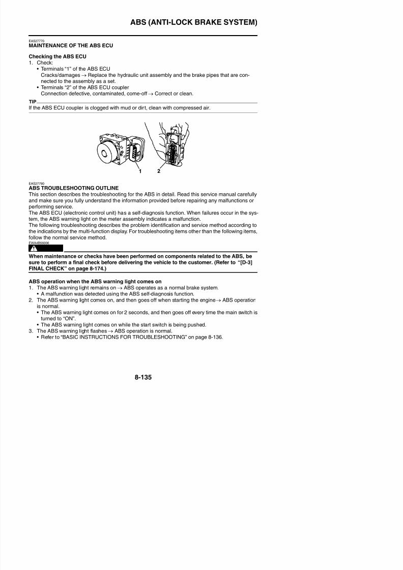
8/21/2019 Fz8 - Service Manual
http://slidepdf.com/reader/full/fz8-service-manual 530/609
TIP
The ABS performs a self-diagnosis test for a few seconds each time the vehicle first starts off after
the main switch was turned on. During this test, a “clicking” noise can be heard from under the seat,
and if the front brake lever or rear brake pedal are even slightly applied, a vibration can be felt at thelever and peal, but these do not indicate a malfunction.
Special precautions for handling and servicing a vehicle equipped with ABSECA4B56024
Care should be taken not to damage components by subjecting them to shocks or pulling on
them with too much force since the ABS components are precisely adjusted.
• The ABS ECU and hydraulic unit are united assemblies and cannot be disassembled.
• The malfunction history is stored in the memory of the ABS ECU. Delete the fault codes when theservice is finished. (This is because the past fault codes will be displayed again if another malfunc-tion occurs.)
EAS27800
BASIC INSTRUCTIONS FOR TROUBLESHOOTING
WARNING
EWA4B56007
• Perform the troubleshooting [A] → [B] → [C] → [D] in order. Be sure to follow the order
since a wrong diagnosis could result if the steps are followed in a different order or omit-ted.
• Use sufficiently charged regular batteries only.
Self-diagnosis using the ABS ECUThe ABS ECU performs a static check of the entire system when the main switch is turned to “ON”.
It also checks for malfunctions while the vehicle is ridden. Since all malfunctions are recorded afterthey are detected, it is possible to check the recorded malfunction data by utilizing the multi-func-tion display when the ABS ECU has entered the self-diagnosis mode.
ABS (ANTI-LOCK BRAKE SYSTEM)
EAS27810
BASIC PROCESS FOR TROUBLESHOOTING
8/21/2019 Fz8 - Service Manual
http://slidepdf.com/reader/full/fz8-service-manual 531/609
ABS (ANTI-LOCK BRAKE SYSTEM)
WARNING
EWA4B56008
When maintenance or checks have been performed on components related to the ABS, besure to perform a final check before delivering the vehicle to the customer. (Refer to “[D-3]
FINAL CHECK” on page 8-174.)
EAS27830
[A] CHECKING THE ABS WARNING LIGHTTurn the main switch to “ON”. (Do not start the engine.)1 The ABS warning light does not come on [B-1]
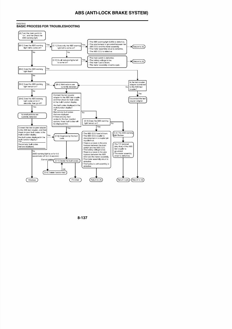
8/21/2019 Fz8 - Service Manual
http://slidepdf.com/reader/full/fz8-service-manual 532/609
1. The ABS warning light does not come on. [B 1]2. The ABS warning light flashes. [B-2]3. The ABS warning light remains on. [B-3]
4. The ABS warning light comes on for 2 seconds, then goes off. [B-4]EAS4B56013
[B-1] THE ABS WARNING LIGHT FAILS TO COME ON1. Only the ABS warning light fails to come on when the main switch is turned to “ON”. [C-1]2. The ABS warning light and all other indicator lights fail to come on. [C-2]
EAS4B56014
[B-2] THE ABS WARNING LIGHT FLASHES1. Test coupler adapter
• Check if the test coupler adapter is connected to the ABS test coupler.• If the test coupler adapter is connected, disconnect it, and then install the protective cap onto
the ABS test coupler.• If the test coupler adapter is not connected, refer to “[B-5] MALFUNCTION ARE CURRENTLY
DETECTED” on page 8-140.
EAS4B56015
[B-3] THE ABS WARNING LIGHT REMAINS ON
1. A malfunction is detected. [B-6]
ABS (ANTI-LOCK BRAKE SYSTEM)
EAS4B56016
[B-4] THE ABS WARNING LIGHT COMES ON FOR 2 SECONDS, THEN GOES OFFRemove the protective cap from the ABS test coupler “1”, and then connect the test coupler adapter“2” to the coupler. The T/C terminal (sky blue) is now grounded.
8/21/2019 Fz8 - Service Manual
http://slidepdf.com/reader/full/fz8-service-manual 533/609
1. The fault code “1” is displayed on the multi-function display (example: fault code ABS_11).
2. The ABS warning light flashes every 0.5 second for more than 6 seconds.
The ABS warning light flashes every 0.5 second if a fault code for a past malfunction is notstored in the memory of the ABS ECU. The ABS warning light flashes quicker if a fault code isdisplayed on the multi-function display. If no fault code is displayed, make sure that the customerunderstands the possible conditions that may cause the ABS warning light to come on or flasheven if the system is normal.
TIP
• The ABS fault codes will not be displayed if a fault code for the fuel injection system is displayedon the multi-function display. To display the ABS fault codes, delete the fuel injection system fault
codes, and then start the check again.• The test coupler adapter must be connected to the ABS test coupler to display the fault codes. If
the adapter is not connected, the ABS warning light will come on or flash, but no fault codes will bedi l d
ABS (ANTI-LOCK BRAKE SYSTEM)
EAS4B56017
[B-5] MALFUNCTION ARE CURRENTLY DETECTEDConnect the test coupler adapter to the ABS test coupler.When the test coupler adapter is connected to the ABS test coupler, the fault codes will be displayed
in the multi-function display. Record all of the displayed fault codes.1. No fault codes are displayed in the multi-function display and the ABS warning light is on. [C-3]2. No fault codes are displayed in the multi-function display and the ABS warning light is flashing.
[C-4]
EAS4B56018
[C-1] ONLY THE ABS WARNING LIGHT FAILS TO COME ON
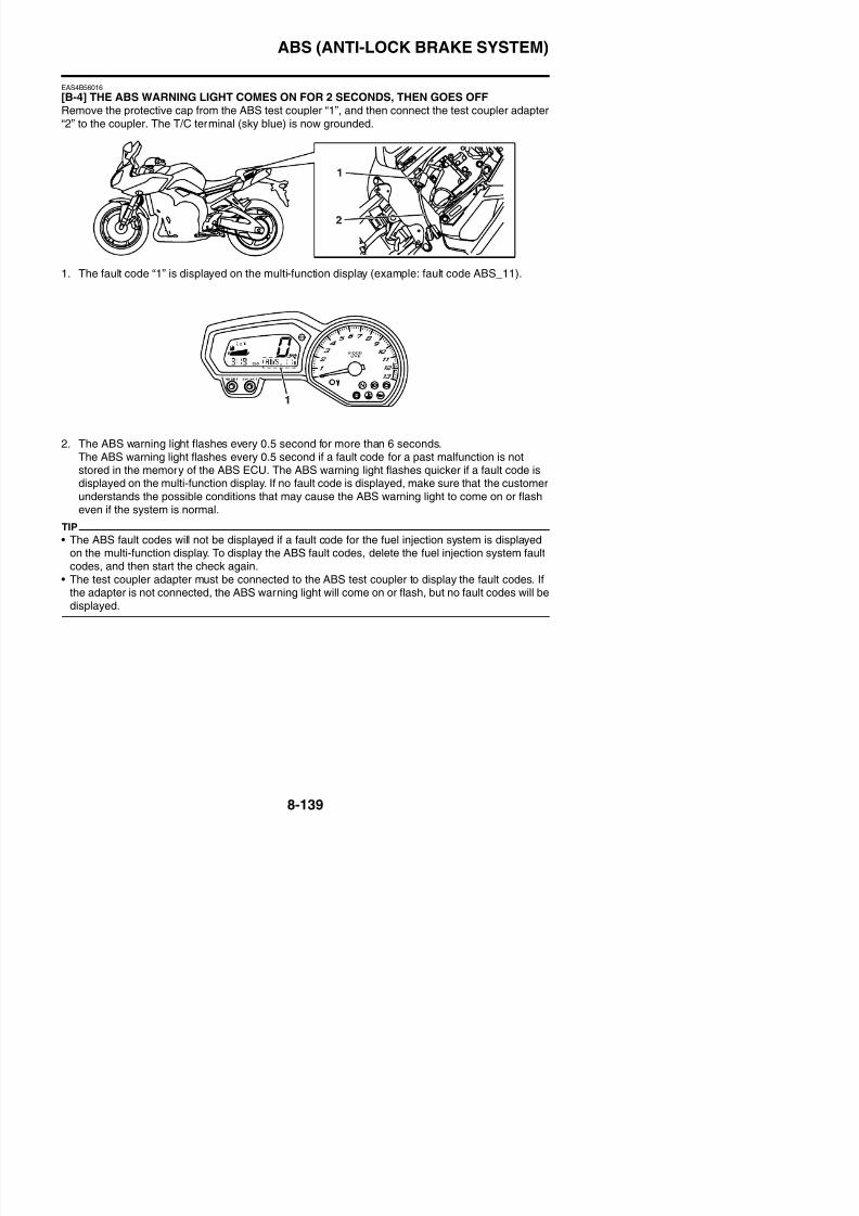
8/21/2019 Fz8 - Service Manual
http://slidepdf.com/reader/full/fz8-service-manual 534/609
[C-1] ONLY THE ABS WARNING LIGHT FAILS TO COME ON1. Check for a short circuit to the ground between the green/red terminal of the ABS ECU coupler
and green/red terminal of the meter assembly.
• If there is no short circuit to the ground, the wire harness is defective. Properly repair orreplace the defective harness.
2. Disconnect the ABS ECU coupler and check that the ABS warning light comes on when themain switch is turned to “ON”.• If the ABS warning light does not come on, the meter assembly circuit (including the ABS
warning light [LED]) is defective. Replace the meter assembly.• If the ABS warning light comes on, the ABS ECU is defective. Replace the hydraulic unit
assembly.
EAS4B56019
[C-2] ALL INDICATOR LIGHTS FAIL TO COME ON1. Main switch
• Check the main switch for continuity.Refer to “CHECKING THE SWITCHES” on page 8-179.
• If there is no continuity, replace the main switch/immobilizer unit.2. Battery
• Check the condition of the battery.
Refer to “CHECKING AND CHARGING THE BATTERY” on page 8-186.• If the battery is defective, clean the battery terminals and recharge it, or replace the battery.
3. Main fuse• Check the fuse for continuity.
Refer to “CHECKING THE FUSES” on page 8-185.• If the main fuse is blown, replace the fuse.
4. Circuit• Check the meter assembly circuit.
Refer to “CIRCUIT DIAGRAM” on page 8-127.• If the meter assembly circuit is open, properly repair or replace the wire harness.
ABS (ANTI-LOCK BRAKE SYSTEM)
EAS4B56020
[C-3] THE ABS WARNING LIGHT REMAINS ON1. The battery voltage is low.
• Check the condition of the battery.
Refer to “CHECKING AND CHARGING THE BATTERY” on page 8-186.• If the battery voltage is low, clean the battery terminals and recharge it, or replace the battery.2. ABS ECU fuse
• Check the ABS ECU fuse for continuity.
Refer to “CHECKING THE FUSES” on page 8-185.• If the ABS ECU fuse is blown, replace the fuse.
8/21/2019 Fz8 - Service Manual
http://slidepdf.com/reader/full/fz8-service-manual 535/609
3. ABS ECU coupler• Check that the ABS ECU coupler is connected properly.• Connect the couplers properly if necessary.
4. There is a break in the wire harness between the main switch and the ABS ECU or between theABS ECU and the ground.• Check for continuity between the Brown/Blue terminal of the main switch coupler and Brown/
Blue terminal of the ABS ECU fuse.• Check for continuity between the Brown/White terminal of the ABS ECU fuse and the Brown/
White terminal of the ABS ECU coupler.• If there is no continuity, the wire harness is defective. Properly repair or replace the wire har-
ness.• Check for continuity between the Black/White terminal of the ABS ECU coupler and the
ground.• If there is no continuity, the wire harness is defective. Properly repair or replace the wire har-
ness.5. There is a break in the wire harness between the ABS ECU and the meter assembly (ABS warn-
ing light).• Check for continuity between the Green/Red terminal of the ABS ECU coupler and the Green/
Red terminal of the meter assembly coupler.• If there is no continuity, the wire harness is defective. Properly repair or replace the defective
harness.6. The meter assembly circuit is defective.
• Disconnect the ABS ECU coupler.• The white/red terminal of the ABS ECU coupler is short-circuited to the ground.• Turn the main switch to “ON”, and then check the ABS warning light.• If the ABS warning light is on, the internal circuit of the meter assembly is defective. Replace
the meter assembly.• If the ABS warning light does not come on, the ABS ECU is defective. Replace the hydraulic
unit assembly.7. The hydraulic unit assembly is defective.
ABS (ANTI-LOCK BRAKE SYSTEM)
EAS4B56022
[C-5] DIAGNOSIS USING THE FAULT CODESConnect the test coupler adapter to the ABS test coupler, and then turn the main switch to “ON”.Information for the fault codes from the ABS ECU is contained in the following table. Refer to this
table for troubleshooting.TIP
Record all of the fault codes displayed and inspect the check points.
Fault code table
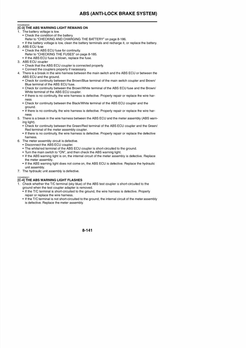
8/21/2019 Fz8 - Service Manual
http://slidepdf.com/reader/full/fz8-service-manual 536/609
Faultcode No.
Symptom Check point
ABS_11*
ABS_25*
Front wheel sensor signal is not
received properly.
• Installation of the front wheel sensor• Front wheel
• Front wheel sensor housing• Front wheel sensor rotor
ABS_12Rear wheel sensor signal is notreceived properly.
• Installation of the rear wheel sensor• Rear wheel• Rear wheel sensor housing• Rear wheel sensor rotor
ABS_13ABS_26
Incorrect signal from the front wheelsensor is detected.
• Installation of the front wheel sensor• Front wheel• Front wheel sensor housing• Front wheel sensor rotor• Hydraulic unit assembly
ABS_14
ABS_27
Incorrect signal from the rear wheel
sensor is detected.
• Installation of the rear wheel sensor• Rear wheel• Rear wheel sensor housing
• Rear wheel sensor rotor• Hydraulic unit assembly
ABS_15No continuity in the front wheel sensorcircuit.
• Continuity of the front wheel sensor circuit• Wire harness (ABS circuit)• Connection of the front wheel sensor cou-
pler and ABS ECU coupler• Front wheel sensor
ABS_16No continuity in the rear wheel sensorcircuit.
• Continuity of the rear wheel sensor circuit• Wire harness (ABS circuit)• Connection of the rear wheel sensor cou-
pler and ABS ECU coupler
ABS (ANTI-LOCK BRAKE SYSTEM)
ABS_24
Brake light signal is not received prop-erly while vehicle is traveling (brake
light circuit, or front or rear brake lightswitch circuit).
• Brake light bulbs
• Wire harness (brake light circuit)• Brake light system couplers and connectors
ABS_31Solenoid relay is defective.Power is not supplied to the solenoidrelay.
• ABS solenoid fuse• Wire harness (battery and ABS ECU circuit)
• Connection of the ABS ECU coupler• Hydraulic unit assembly
Faultcode No.
Symptom Check point
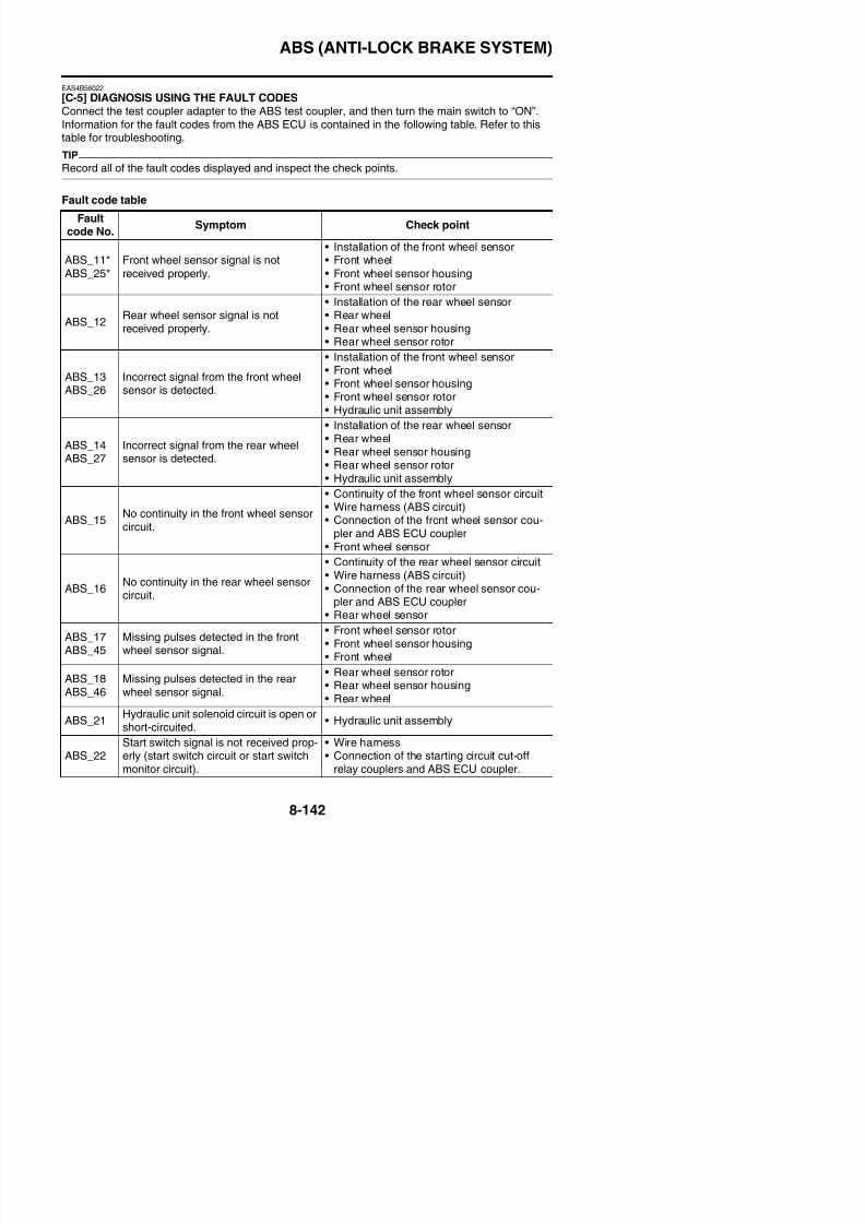
8/21/2019 Fz8 - Service Manual
http://slidepdf.com/reader/full/fz8-service-manual 537/609
y• Hydraulic unit assembly
ABS_32Hydraulic unit solenoid relay is short-
circuited.
• Hydraulic unit assembly
ABS_33ABS motor is defective.Power is not supplied to the ABS motor.
• Battery voltage
• ABS motor fuse• Wire harness (ABS circuit)• Connection of the ABS ECU coupler and
starter relay coupler• Hydraulic unit assembly
ABS_34Hydraulic unit ABS motor relay is short-
circuited.
• Hydraulic unit assembly
ABS_41
Front wheel will not recover from thelocking tendency even though the sig-nal is continuously transmitted from theABS ECU to release the hydraulic pres-sure.
• Brake dragging• Brake fluid• Hydraulic unit operation tests• Front wheel brake lines• Hydraulic unit assembly
ABS_42ABS_47
Rear wheel will not recover from thelocking tendency even though the sig-
nal is continuously transmitted from theABS ECU to release the hydraulic pres-sure.
• Brake dragging• Brake fluid
• Hydraulic unit operation tests• Rear wheel brake lines• Hydraulic unit assembly
ABS_43Incorrect signal from the front wheelsensor is detected.
• Installation of the front wheel sensor• Front wheel sensor housing• Front wheel sensor rotor
ABS_44Incorrect signal from the rear wheel
sensor is detected.
• Installation of the rear wheel sensor• Rear wheel sensor housing• Rear wheel sensor rotor
ABS 51P l i hi h
• Battery voltage• Battery terminal
ABS (ANTI-LOCK BRAKE SYSTEM)
ABS_56Hydraulic unit sensor power monitor cir-cuit is abnormal.
• Hydraulic unit assembly
ABS_63 Front wheel sensor power is abnormal.• Front wheel sensor lead• Wire harness• Hydraulic unit assembly
ABS_64 Rear wheel sensor power is abnormal.• Rear wheel sensor lead• Wire harness• Hydraulic unit assembly
Faultcode No.
Symptom Check point
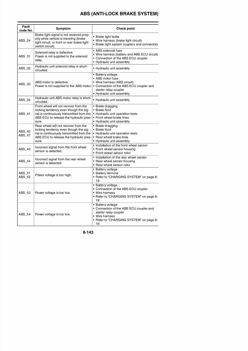
8/21/2019 Fz8 - Service Manual
http://slidepdf.com/reader/full/fz8-service-manual 538/609
* A fault code is indicated if the rear wheel rotates for longer than about 20 seconds (fault code No.ABS_11) or for longer than about 2 seconds (fault code No. ABS_25) with the front wheel stopped(e.g., when the vehicle is on the suitable stand).
TIP
Fault codes Nos. ABS_15 (front wheel) and ABS_16 (rear wheel) are indicated if a defective con-nection is detected in the front or rear wheel sensor when the vehicle is not being ridden.
• Hydraulic unit assembly
ABS (ANTI-LOCK BRAKE SYSTEM)
Fault code No.ABS_11
ABS_25Symptom
Front wheel sensor signal is not received prop-
erly.
OrderItem/components and probable
causeCheck or maintenance job
Reinstatementconfirmationmethod
1 Installed condition of wheel sensor. Check for looseness. Repair orreplace the wheel sensor if nec-essary.
• Turn the mainswitch to “ON”and checkthat the ABSwarning light
2 Installed condition of wheel bearings,l h i d
Check the components for loose-di t ti d b d
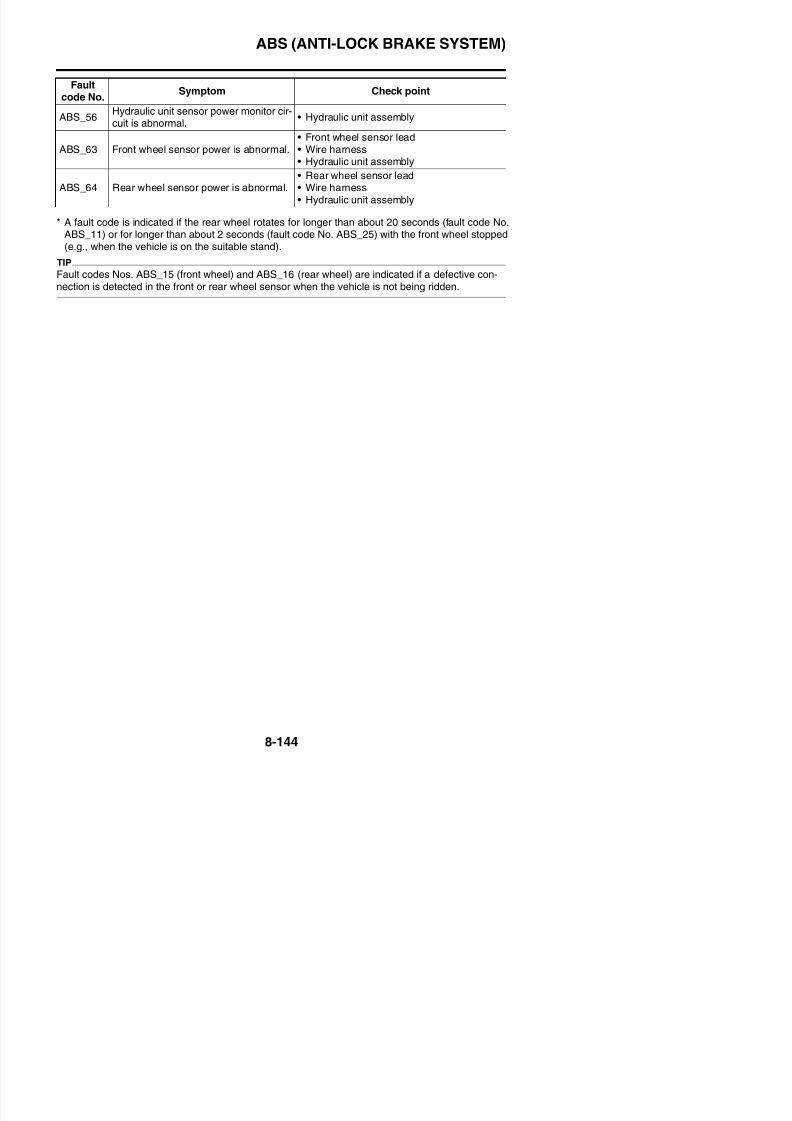
8/21/2019 Fz8 - Service Manual
http://slidepdf.com/reader/full/fz8-service-manual 539/609
TIP
With front wheel stopped, rear wheel was rotated for longer than about 20 seconds (fault code No.
ABS_11) or for longer than about 2 seconds (fault code No. ABS_25).
warning lightcomes on for2 seconds,then goes off.
• Perform a trialrun at a con-
stant speed of30 km/h andcheck that theABS warninglight does notcome on.
axle, sensor housing, and sensorrotor.
ness, distortion, and bends.Refer to “CHECKING THE
FRONT WHEEL” on page 4-14.3 Foreign material inside sensor hous-
ing.Check the interior of the sensorhousing and the surface of thesensor rotor for foreign material,such as metal particles. Clean thesensor housing and sensor rotorif necessary.Refer to “MAINTENANCE OF
THE FRONT WHEEL SENSORAND SENSOR ROTOR” on page4-15.
4 Defective sensor rotor. Check the surface of the sensorrotor for damage. Replace thesensor rotor if there is visibledamage.Refer to “MAINTENANCE OF
THE FRONT WHEEL SENSORAND SENSOR ROTOR” on page4-15.
ABS (ANTI-LOCK BRAKE SYSTEM)
Fault code No. ABS_12 SymptomRear wheel sensor signal is not received prop-
erly.
OrderItem/components and probable
causeCheck or maintenance job
Reinstatementconfirmationmethod
1 Installed condition of wheel sensor. Check for looseness. Repair orreplace the wheel sensor if nec-essary.
• Turn the mainswitch to “ON”and checkthat the ABSwarning light
2 Installed condition of wheel bearings,axle sensor housing and sensor
Check the components for loose-ness distortion and bends
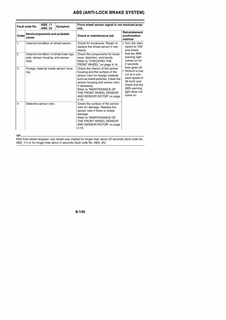
8/21/2019 Fz8 - Service Manual
http://slidepdf.com/reader/full/fz8-service-manual 540/609
warning lightcomes on for2 seconds,then goes off.
• Perform a trialrun at a con-
stant speed of30 km/h andcheck that theABS warninglight does notcome on.
axle, sensor housing, and sensorrotor.
ness, distortion, and bends.Refer to “CHECKING THE REAR
WHEEL” on page 4-24.3 Foreign material inside sensor hous-
ing.Check the interior of the sensorhousing and the surface of thesensor rotor for foreign material,such as metal particles. Clean thesensor housing and sensor rotorif necessary.Refer to “MAINTENANCE OF
THE REAR WHEEL SENSORAND SENSOR ROTOR” on page4-25.
4 Defective sensor rotor. Check the surface of the sensorrotor for damage. Replace thesensor rotor if there is visibledamage.Refer to “MAINTENANCE OF
THE REAR WHEEL SENSORAND SENSOR ROTOR” on page4-25.
ABS (ANTI-LOCK BRAKE SYSTEM)
Fault code No.ABS_13
ABS_26Symptom
Incorrect signal from the front wheel sensor is
detected.
OrderItem/components and probable
causeCheck or maintenance job
Reinstatementconfirmationmethod
1 Installed condition of wheel sensor. Check for looseness. Repair orreplace the wheel sensor if nec-essary.
• Turn the mainswitch to “ON”and checkthat the ABSwarning light
2 Installed condition of wheel bearings,axle sensor housing and sensor
Check the components for loose-ness distortion and bends
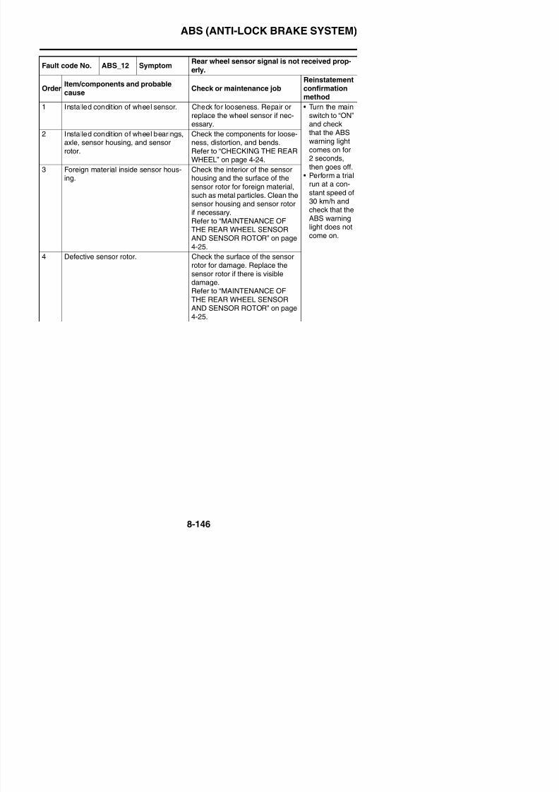
8/21/2019 Fz8 - Service Manual
http://slidepdf.com/reader/full/fz8-service-manual 541/609
TIP
Vehicle possibly ridden on uneven roads.
warning lightcomes on for2 seconds,then goes off.
• Perform a trialrun at a con-
stant speed of30 km/h andcheck that theABS warninglight does notcome on.
axle, sensor housing, and sensorrotor.
ness, distortion, and bends.Refer to “CHECKING THE
FRONT WHEEL” on page 4-14.3 Foreign material inside sensor hous-
ing.Check the interior of the sensorhousing and the surface of thesensor rotor for foreign material,such as metal particles. Clean thesensor housing and sensor rotorif necessary.Refer to “MAINTENANCE OF
THE FRONT WHEEL SENSORAND SENSOR ROTOR” on page4-15.
4 Defective sensor rotor. Check the surface of the sensorrotor for damage. If there is visibledamage, replace the sensor rotor.Refer to “MAINTENANCE OFTHE FRONT WHEEL SENSOR
AND SENSOR ROTOR” on page4-15.
5 Hydraulic unit assembly internal mal-function.
Replace the hydraulic unit assem-bly.
ABS (ANTI-LOCK BRAKE SYSTEM)
Fault code No.ABS_14
ABS_27Symptom
Incorrect signal from the rear wheel sensor is
detected.
OrderItem/components and probable
causeCheck or maintenance job
Reinstatementconfirmationmethod
1 Installed condition of wheel sensor. Check for looseness. Repair orreplace the wheel sensor if nec-essary.
• Turn the mainswitch to “ON”and checkthat the ABSwarning light
2 Installed condition of wheel bearings,axle sensor housing and sensor
Check the components for loose-ness distortion and bends
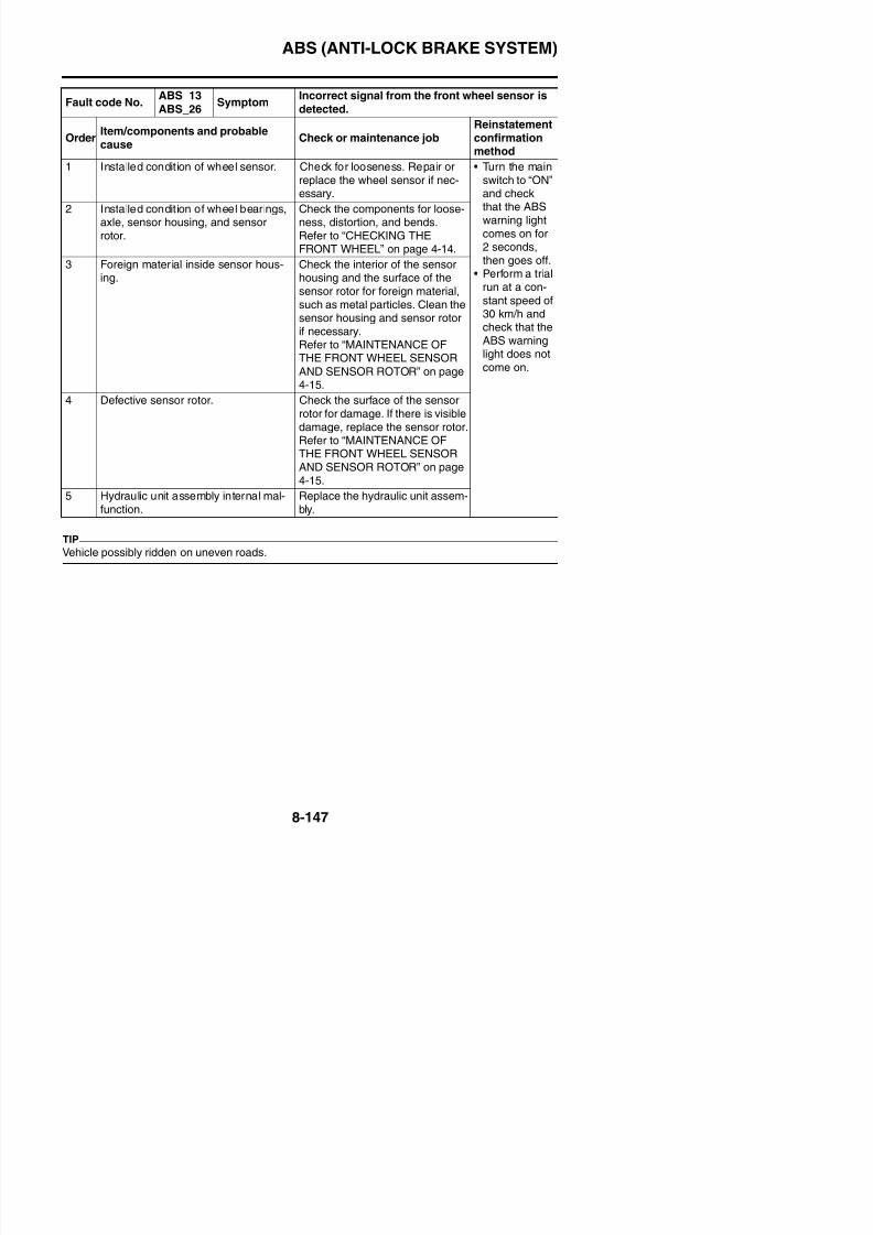
8/21/2019 Fz8 - Service Manual
http://slidepdf.com/reader/full/fz8-service-manual 542/609
TIP
Vehicle possibly ridden on uneven roads.
g gcomes on for2 seconds,then goes off.
• Perform a trialrun at a con-
stant speed of30 km/h andcheck that theABS warninglight does notcome on.
axle, sensor housing, and sensorrotor.
ness, distortion, and bends.Refer to “CHECKING THE REAR
WHEEL” on page 4-24.3 Foreign material inside sensor hous-
ing.Check the interior of the sensorhousing and the surface of thesensor rotor for foreign material,such as metal particles. Clean thesensor housing and sensor rotorif necessary.Refer to “MAINTENANCE OF
THE REAR WHEEL SENSORAND SENSOR ROTOR” on page4-25.
4 Defective sensor rotor. Check the surface of the sensorrotor for damage. If there is visibledamage, replace the sensor rotor.Refer to “MAINTENANCE OFTHE REAR WHEEL SENSOR
AND SENSOR ROTOR” on page4-25.
5 Hydraulic unit assembly internal mal-function.
Replace the hydraulic unit assem-bly.
Fault code No. ABS_15 Symptom No continuity in the front wheel sensor circuit.
OrderItem/components and probable
Check or maintenance jobReinstatementconfirmation
ABS (ANTI-LOCK BRAKE SYSTEM)
2 Wire harness continuity. • Check for continuity betweenthe blue terminal “1” and theblue terminal “3” and betweenthe green terminal “2” and the
green terminal “4”.• If there is no continuity, the wire
Fault code No. ABS_15 Symptom No continuity in the front wheel sensor circuit.
OrderItem/components and probablecause
Check or maintenance jobReinstatementconfirmationmethod
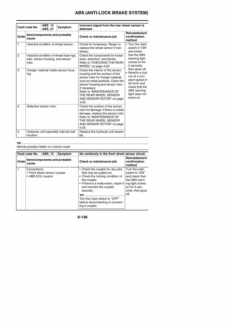
8/21/2019 Fz8 - Service Manual
http://slidepdf.com/reader/full/fz8-service-manual 543/609
harness is defective. Properlyrepair or replace the wire har-
ness.• Check that there is no continuity
between the ground and theblue terminal “1” or blue termi-nal “3” and between the groundand the green terminal “2” orgreen terminal “4”.
• If there is continuity, the wire
harness is defective. Properlyrepair or replace the wire har-ness.
• Check that there is no continuitybetween the blue terminal “1”and the green terminal “2” andbetween the blue terminal “3”and the green terminal “4”.
• If there is continuity, the wireharness is defective. Properlyrepair or replace the wire har-ness.
ABS (ANTI-LOCK BRAKE SYSTEM)
3 Defective wheel sensor. If the above items were per-formed and no malfunctions werefound, connect the ABS ECUcoupler and front wheel sensor
coupler, and then delete the faultcodes. If fault code No. ABS_15
ld b d l d h f
Fault code No. ABS_15 Symptom No continuity in the front wheel sensor circuit.
OrderItem/components and probablecause
Check or maintenance jobReinstatementconfirmationmethod
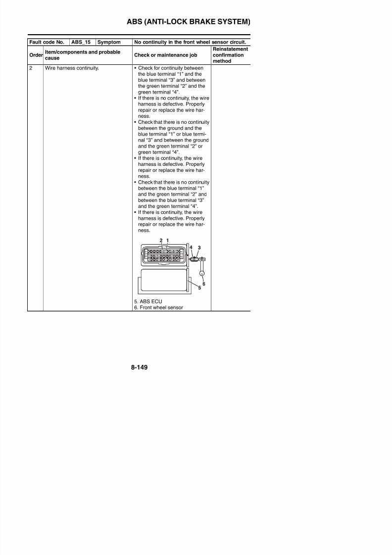
8/21/2019 Fz8 - Service Manual
http://slidepdf.com/reader/full/fz8-service-manual 544/609
could not be deleted, the frontwheel sensor is defective.
Replace the front wheel sensor.
TIP
Before deleting the fault codes,record all of the fault codes andperform the related checks andmaintenance.
Fault code No. ABS_16 Symptom No continuity in the rear wheel sensor circuit.
OrderItem/components and probablecause
Check or maintenance jobReinstatementconfirmationmethod
1 Connections• Rear wheel sensor coupler• ABS ECU coupler
• Check the coupler for any pinsthat may be pulled out.
• Check the locking condition of
the coupler.• If there is a malfunction, repair itand connect the couplersecurely.
TIP
Turn the main switch to “OFF”before disconnecting or connect-ing a coupler.
Turn the mainswitch to “ON”and check that
the ABS warn-ing light comeson for 2 sec-onds, then goesoff.
ABS (ANTI-LOCK BRAKE SYSTEM)
2 Wire harness continuity. • Check for continuity betweenthe white terminal “1” and thewhite terminal “3” and betweenthe white/red terminal “2” and
the white/red terminal “4”.• If there is no continuity, the wire
h i d f ti P l
Fault code No. ABS_16 Symptom No continuity in the rear wheel sensor circuit.
OrderItem/components and probablecause
Check or maintenance jobReinstatementconfirmationmethod
8/21/2019 Fz8 - Service Manual
http://slidepdf.com/reader/full/fz8-service-manual 545/609
harness is defective. Properlyrepair or replace the wire har-
ness.• Check that there is no continuity
between the ground and thewhite terminal “1” or white ter-minal “3” and between theground and the white/red termi-nal “2” or white/red terminal “4”.
• If there is continuity, the wire
harness is defective. Properlyrepair or replace the wire har-ness.
• Check that there is no continuitybetween the white terminal “1”and the white/red terminal “2”and between the white terminal“3” and the white/red terminal
“4”.• If there is continuity, the wire
harness is defective. Properlyrepair or replace the wire har-ness.
ABS (ANTI-LOCK BRAKE SYSTEM)
3 Defective wheel sensor. If the above items were per-formed and no malfunctions werefound, connect the ABS ECUcoupler and rear wheel sensor
coupler, and then delete the faultcodes. If fault code No. ABS_16could not be deleted the rear
Fault code No. ABS_16 Symptom No continuity in the rear wheel sensor circuit.
OrderItem/components and probablecause
Check or maintenance jobReinstatementconfirmationmethod
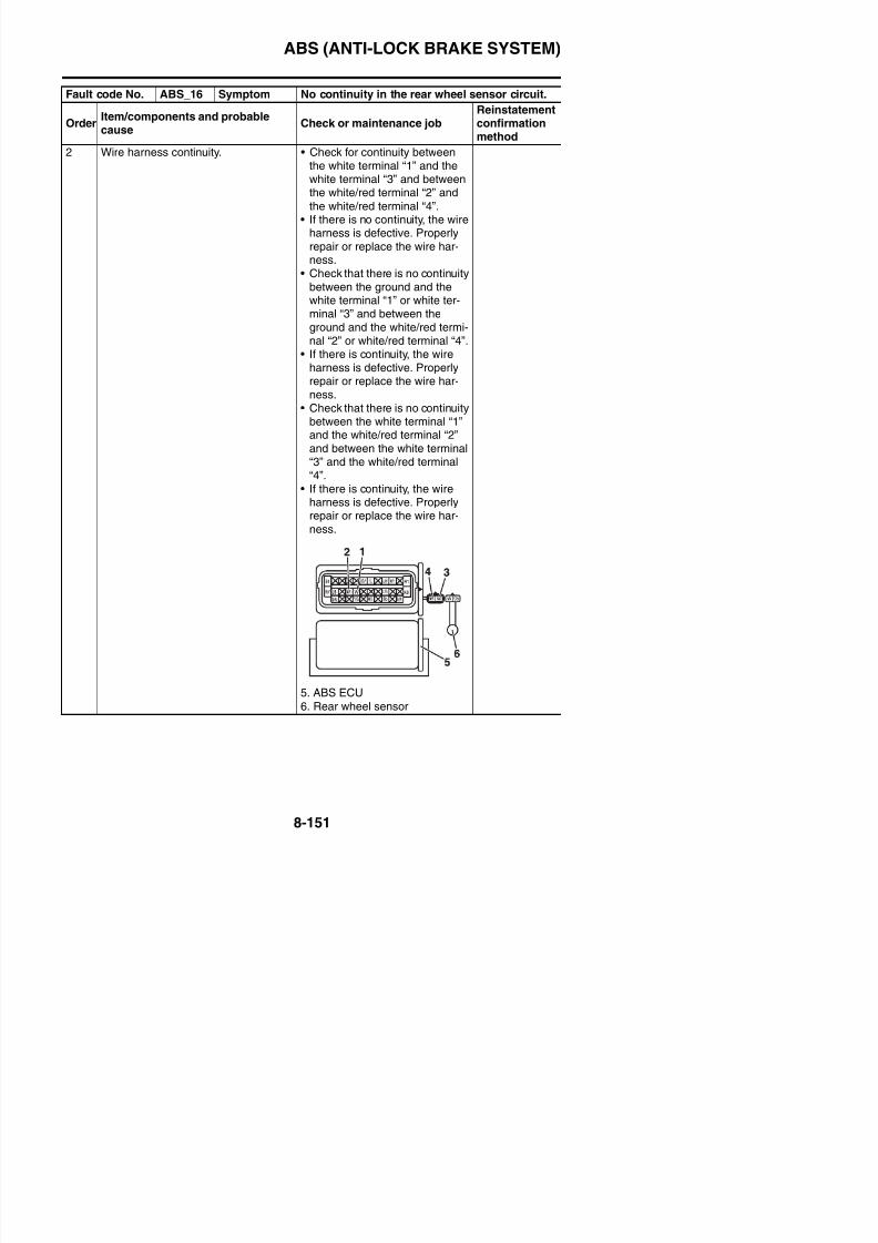
8/21/2019 Fz8 - Service Manual
http://slidepdf.com/reader/full/fz8-service-manual 546/609
could not be deleted, the rearwheel sensor is defective.
Replace the rear wheel sensor.
TIP
Before deleting the fault codes,record all of the fault codes andperform the related checks andmaintenance.
Fault code No.ABS_17
ABS_45Symptom
Missing pulses detected in the front wheel sen-
sor signal.
OrderItem/components and probablecause
Check or maintenance jobReinstatementconfirmationmethod
1 Installed condition of wheel bearings,axle, sensor housing, and sensor
rotor.
Check the components for loose-ness, distortion, and bends.
Refer to “CHECKING THEFRONT WHEEL” on page 4-14.
• Turn the mainswitch to “ON”
and checkthat the ABSwarning lightcomes on for2 seconds,then goes off.
• Perform a trialrun at a con-
stant speed of30 km/h andcheck that theABS warning
2 Foreign material inside sensor hous-ing.
Check the interior of the sensorhousing and the surface of thesensor rotor for foreign material,such as metal particles. Clean the
sensor housing and sensor rotorif necessary.
Refer to “MAINTENANCE OFTHE FRONT WHEEL SENSORAND SENSOR ROTOR” on page4 15
ABS (ANTI-LOCK BRAKE SYSTEM)
Fault code No.ABS_18
ABS_46Symptom
Missing pulses detected in the rear wheel sen-
sor signal.
OrderItem/components and probable
cause
Check or maintenance jobReinstatementconfirmation
method
1 Installed condition of wheel bearings,axle, sensor housing, and sensorrotor.
Check the components for loose-ness, distortion, and bends.Refer to “CHECKING THE REARWHEEL” on page 4-24.
• Turn the mainswitch to “ON”and checkthat the ABSwarning lightcomes on for
2 Foreign material inside sensor hous-i
Check the interior of the sensorh i d th f f th
8/21/2019 Fz8 - Service Manual
http://slidepdf.com/reader/full/fz8-service-manual 547/609
comes on for2 seconds,then goes off.
• Perform a trialrun at a con-
stant speed of30 km/h andcheck that theABS warninglight does not
come on.
ing. housing and the surface of thesensor rotor for foreign material,such as metal particles. Clean the
sensor housing and sensor rotorif necessary.Refer to “MAINTENANCE OFTHE REAR WHEEL SENSORAND SENSOR ROTOR” on page4-25.
3 Defective sensor rotor. • Check the surface of the sensorrotor for damage.• If there is visible damage,
replace the sensor rotor.
Fault code No. ABS_21 SymptomHydraulic unit solenoid circuit is open or short-circuited.
Order Item/components and probablecause Check or maintenance job
Reinstatement
confirmationmethod
1 Open or short circuit in solenoid cir-
cuit.
Replace the hydraulic unit assem-
bly.
• Turn the main
switch to “ON”and checkthat the ABSwarning lightcomes on for
2 seconds,then goes off.
• Perform
ABS (ANTI-LOCK BRAKE SYSTEM)
Fault code No. ABS_22 Symptom
Start switch signal is not received properly
(start switch circuit or start switch monitor cir-cuit).
Order Item/components and probablecause Check or maintenance job
Reinstatement
confirmationmethod
1 Engine startability. Check the electric starting sys-tem.Refer to “ELECTRIC STARTINGSYSTEM” on page 8-11.
• Push the startswitch andcheck that theengine starts.
• Turn the main2 Connections • Check the coupler for any pins
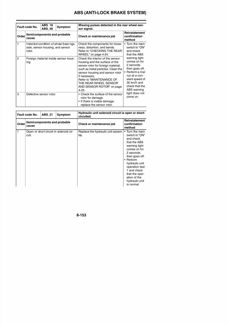
8/21/2019 Fz8 - Service Manual
http://slidepdf.com/reader/full/fz8-service-manual 548/609
• Turn the mainswitch to “ON”and checkthat the ABSwarning light
comes on for2 seconds,then goes off.
• Check that theABS warning
light comes onwhile the startswitch is beingpushed.
2 Connections• Starter relay coupler• ABS ECU coupler
• Right handlebar switch coupler
• Check the coupler for any pinsthat may be pulled out.
• Check the locking condition of
the coupler.• If there is a malfunction, repair it
and connect the couplersecurely.
TIP
Turn the main switch to “OFF”
before disconnecting or connect-ing a coupler.
3 Open or short circuit in wire harness. • Repair or replace if there is anopen or short circuit.
• Between ABS ECU coupler andstarter relay coupler.(Blue/white–Blue/white)
• Between ABS ECU coupler andright handlebar switch (startswitch) coupler.(White/blue–Blue/white)
ABS (ANTI-LOCK BRAKE SYSTEM)
Fault code No. ABS_24 Symptom
Brake light signal is not received properly while
vehicle is traveling (brake light circuit, or frontor rear brake light switch circuit).
Order Item/components and probablecause Check or maintenance job
Reinstatement
confirmationmethod
1 Brake light operation.• Burned-out brake light bulb
• Check the brake light. Repair orreplace the brake light if neces-sary.Refer to “CHECKING THEBULBS AND BULB SOCKETS”
• Check that thebrake lightcomes onwhen the frontor rear brake
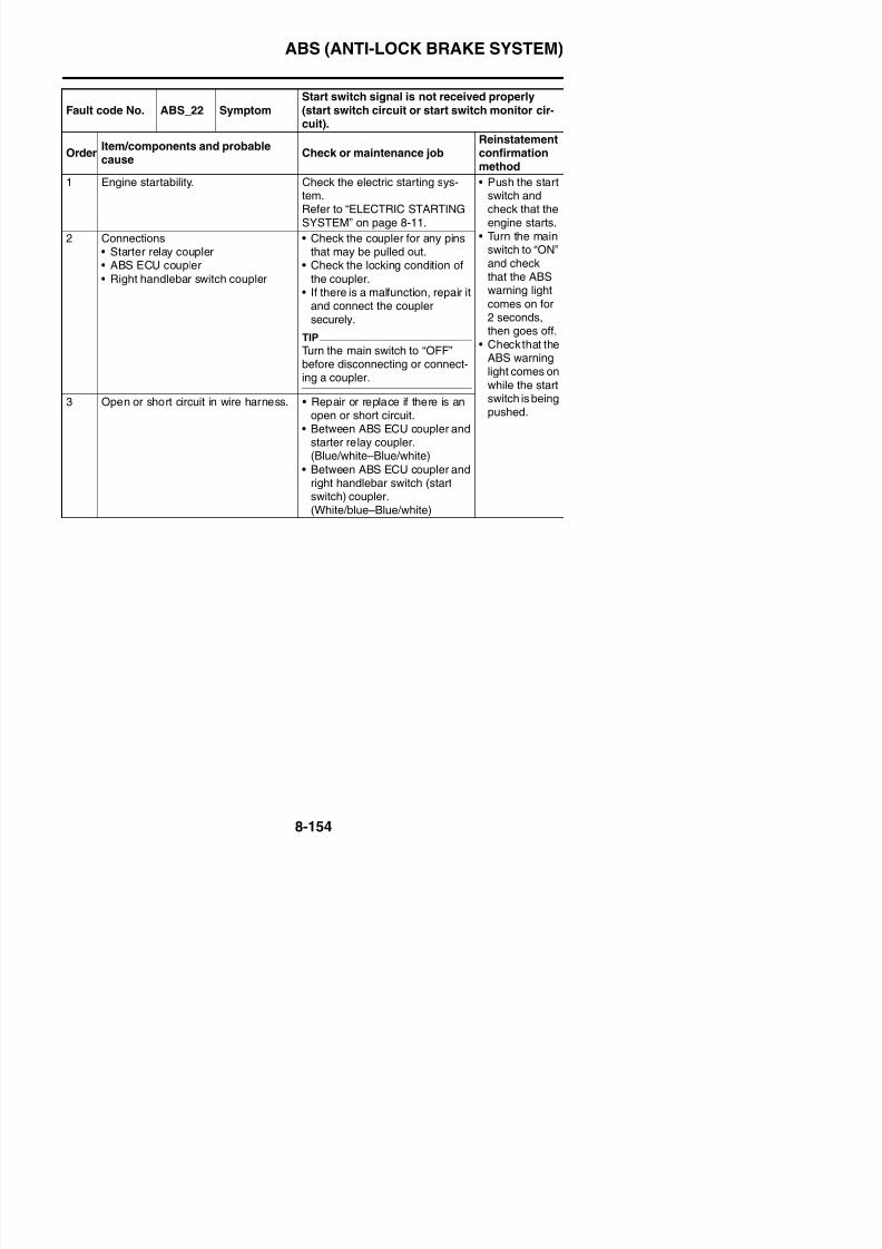
8/21/2019 Fz8 - Service Manual
http://slidepdf.com/reader/full/fz8-service-manual 549/609
BULBS AND BULB SOCKETSon page 8-184.
or rear brakeis applied.
• Turn the mainswitch to “ON”and checkthat the ABSwarning lightcomes on for2 seconds,then goes off.
2 Connections
• ABS ECU coupler• Front brake light switch connectors• Rear brake light switch coupler
• Check the coupler for any pins
that may be pulled out.• Check the locking condition of
the coupler.• If there is a malfunction, repair
it and connect the couplersecurely.
TIPTurn the main switch to “OFF”before disconnecting or connect-ing a coupler.
3 Open or short circuit in wire harness. • Repair or replace if there is anopen or short circuit.
• Between rear brake light switch
coupler and ABS ECU coupler.(Yellow–Yellow/green)
• Between front brake light switchconnectors and ABS ECU cou-pler.(Green/yellow–Yellow/green)
4 Water inside switch. Use compressed air to blow out
the water.
ABS (ANTI-LOCK BRAKE SYSTEM)
Fault code No. ABS_31 SymptomSolenoid relay is defective.
Power is not supplied to the solenoid relay.
OrderItem/components and probable
cause
Check or maintenance jobReinstatementconfirmation
method1 Battery voltage Recharge or replace the battery.
Refer to “CHECKING ANDCHARGING THE BATTERY” onpage 8-186.
Turn the mainswitch to “ON”and check thatthe ABS warn-ing light comeson for 2 sec-
2 Blown ABS solenoid fuse. Check the ABS solenoid fuse. Ifthe ABS solenoid fuse is blown
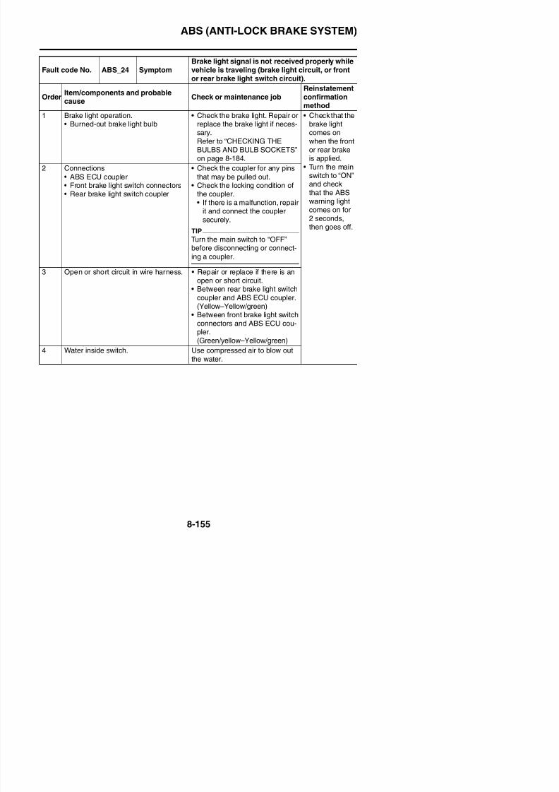
8/21/2019 Fz8 - Service Manual
http://slidepdf.com/reader/full/fz8-service-manual 550/609
on for 2 seconds, then goes
off.
the ABS solenoid fuse is blown,replace the fuse and check thewire harness.
Refer to “CHECKING THEFUSES” on page 8-185.
3 Connections• ABS ECU coupler
• Check the coupler for any pinsthat may be pulled out.
• Check the locking condition ofthe coupler.
• If there is a malfunction, repair itand connect the couplersecurely.
TIP
Turn the main switch to “OFF”before disconnecting or connect-
ing a coupler.
4 Open or short circuit in wire harness. • Repair or replace if there is anopen or short circuit.• Between ABS ECU coupler and
ABS solenoid fuse.(Red–Red)
• Between ABS ECU coupler andground.
(Black/yellow–Black/yellow)
5 Hydraulic unit assembly internal mal-function. Replace the hydraulic unit assem-bly.
ABS (ANTI-LOCK BRAKE SYSTEM)
Fault code No. ABS_32 Symptom Hydraulic unit solenoid relay is short-circuited.
OrderItem/components and probablecause
Check or maintenance jobReinstatementconfirmationmethod
1 Short circuit in solenoid relay. Replace the hydraulic unit assem-bly.
• Turn the mainswitch to “ON”and checkthat the ABSwarning lightcomes on for2 seconds,
2 Hydraulic unit assembly internal mal-function.
Replace the hydraulic unit assem-bly.
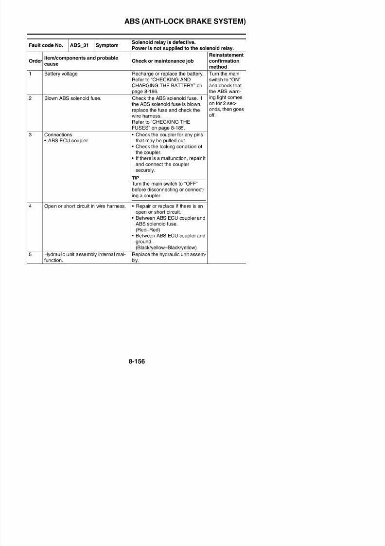
8/21/2019 Fz8 - Service Manual
http://slidepdf.com/reader/full/fz8-service-manual 551/609
,then goes off.
• Performhydraulic unitoperation test
1 and checkthat the oper-ation of thehydraulic unitis normal.
ABS (ANTI-LOCK BRAKE SYSTEM)
Fault code No. ABS_33 SymptomABS motor is defective.
Power is not supplied to the ABS motor.
OrderItem/components and probable
cause
Check or maintenance jobReinstatementconfirmation
method1 Battery voltage Recharge or replace the battery.
Refer to “CHECKING ANDCHARGING THE BATTERY” onpage 8-186.
• Turn the mainswitch to “ON”and checkthat the ABSwarning lightcomes on for
2 Blown ABS motor fuse. Check the ABS motor fuse. If theABS motor fuse is blown, replace
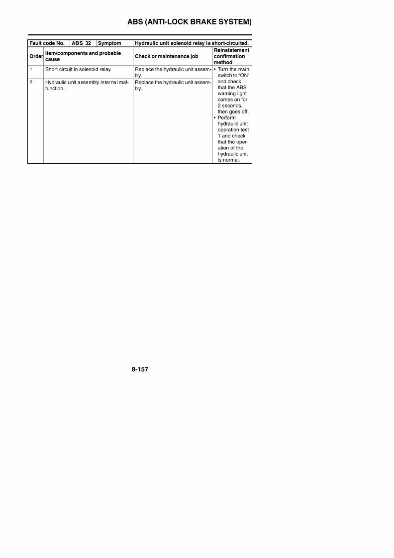
8/21/2019 Fz8 - Service Manual
http://slidepdf.com/reader/full/fz8-service-manual 552/609
2 seconds,
then goes off.• Perform
hydraulic unit
operation test1 and checkthat the oper-ation of thehydraulic unit
is normal.
, pthe fuse and check the wire har-ness.
Refer to “CHECKING THEFUSES” on page 8-185.
3 Connections• ABS ECU coupler• Starter relay coupler
• Check the coupler for any pinsthat may be pulled out.
• Check the locking condition ofthe coupler.
• If there is a malfunction, repair itand connect the couplersecurely.
TIP
Turn the main switch to “OFF”before disconnecting or connect-
ing a coupler.
4 Open or short circuit in wire harness. • Repair or replace if there is anopen or short circuit.• Between ABS ECU coupler and
ABS motor fuse.(Red/black–Red/black)
• Between ABS ECU coupler andground.
(Black/yellow–Black/yellow)
5 Hydraulic unit assembly internal mal-function. Replace the hydraulic unit assem-bly.
ABS (ANTI-LOCK BRAKE SYSTEM)
Fault code No. ABS_34 SymptomHydraulic unit ABS motor relay is short-cir-
cuited.
OrderItem/components and probable
cause
Check or maintenance jobReinstatementconfirmation
method1 Short circuit in ABS motor relay. Replace the hydraulic unit assem-
bly.• Turn the main
switch to “ON”and checkthat the ABSwarning lightcomes on for
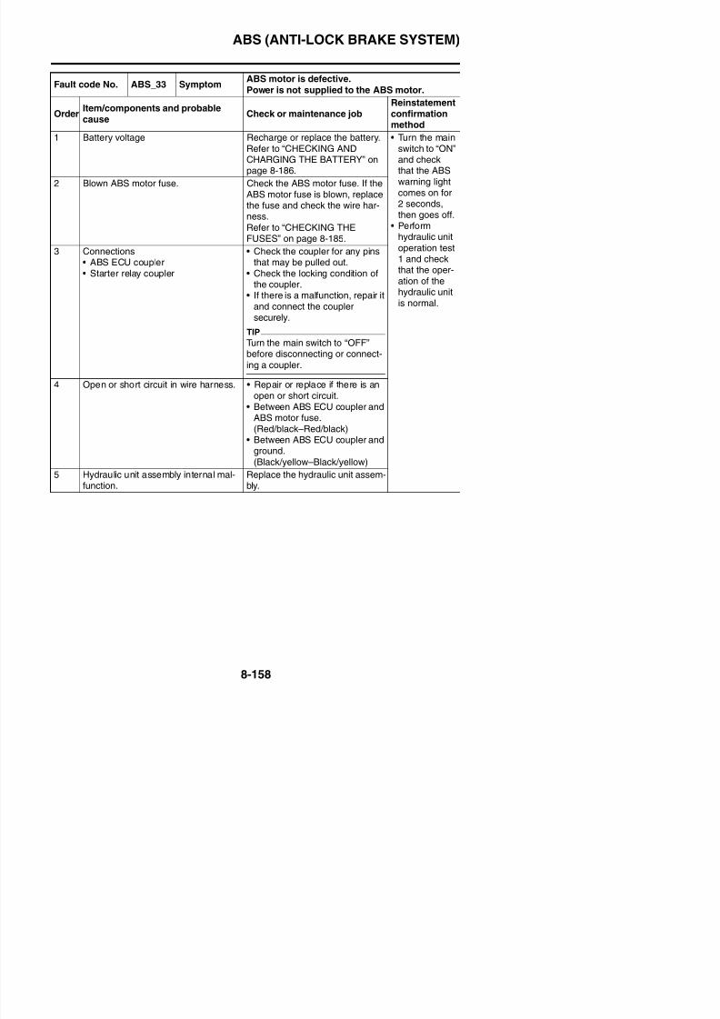
8/21/2019 Fz8 - Service Manual
http://slidepdf.com/reader/full/fz8-service-manual 553/609
2 seconds,
then goes off.• Perform
hydraulic unit
operation test1 and checkthat the oper-ation of thehydraulic unit
is normal.
ABS (ANTI-LOCK BRAKE SYSTEM)
Fault code No. ABS_41 Symptom
Front wheel will not recover from the locking
tendency even though the signal is continu-ously transmitted from the ABS ECU to releasethe hydraulic pressure (when the battery volt-
age is normal)
OrderItem/components and probablecause
Check or maintenance jobReinstatementconfirmationmethod
1 Rotation of wheel • Check that there is no brakedisc drag on the front wheel andmake sure that it rotates
hl
Perform hydrau-lic unit opera-tion test 1 andh k h h

8/21/2019 Fz8 - Service Manual
http://slidepdf.com/reader/full/fz8-service-manual 554/609
smoothly.
• Check the front wheel axle forloose bearings and bends, andthe brake discs for distortion.
Refer to “CHECKING THEFRONT BRAKE DISCS” onpage 4-35.
check that the
operation of thehydraulic unit isnormal.
2 Brake master cylinder and brake cali-per
• Check that the brake fluid pres-sure is correctly transmitted tothe brake calipers when thefront brake lever is operatedand that the pressuredecreases when the lever isreleased.
3 Brake fluid • Visually check the brake fluid inthe brake master cylinder reser-voir for water, foreign materials,solidification, and contamina-tion.
• Check for air in the brake lines.
ABS (ANTI-LOCK BRAKE SYSTEM)
4 Brake lines • Check the brake lines for kinksand deterioration.
WARNING
EWA4B56009
Fault code No. ABS_41 Symptom
Front wheel will not recover from the lockingtendency even though the signal is continu-ously transmitted from the ABS ECU to release
the hydraulic pressure (when the battery volt-
age is normal)
OrderItem/components and probablecause
Check or maintenance jobReinstatementconfirmationmethod
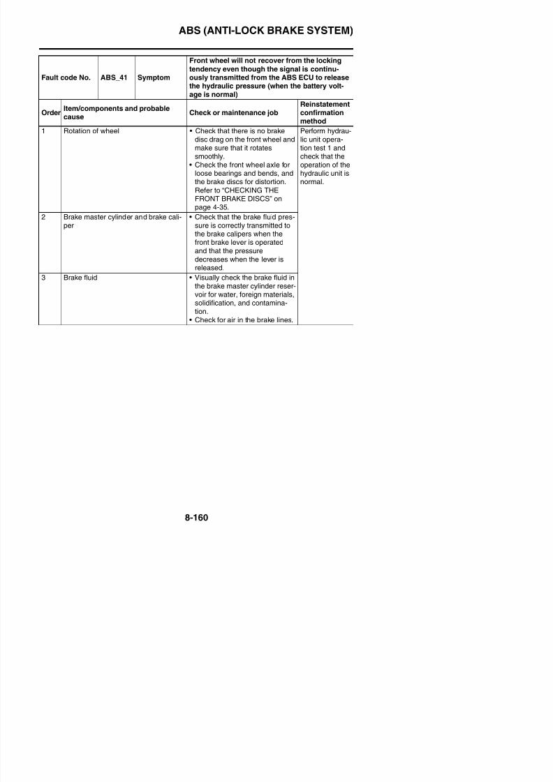
8/21/2019 Fz8 - Service Manual
http://slidepdf.com/reader/full/fz8-service-manual 555/609
WARNING
Only use genuine Yamahaparts. Using other brake pipes,hoses and union bolts may
close the brake lines.
• Check that the connections ofthe brake lines from the brakemaster cylinder to the hydraulicunit and from the hydraulic unit
to the front brake calipers arecorrect.
See WARNING and TIP.
5 Hydraulic unit assembly If the malfunction is not correctedafter checking items (1) to (3) andfront brake hose outlet, replacethe hydraulic unit assembly. Besure to connect the brake pipes
ABS (ANTI-LOCK BRAKE SYSTEM)
TIP
• If the brake pipe inlet and outlet connections are incorrect on the hydraulic unit, the front brakelever will be pulled to its full-stroke position without responding, and then it will be pushed backslowly without pulsating when the final check on page “[D-3] FINAL CHECK” on page 8-174 is per-
formed.• If the front and rear brake pipe connections are reversed on the hydraulic unit, the pulsating action
in the front brake lever and rear brake pedal will be performed in the reverse order when the finalcheck on page “[D-3] FINAL CHECK” on page 8-174 is performed.
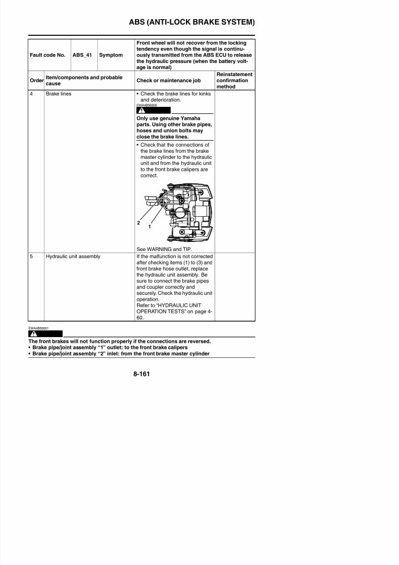
8/21/2019 Fz8 - Service Manual
http://slidepdf.com/reader/full/fz8-service-manual 556/609
ABS (ANTI-LOCK BRAKE SYSTEM)
Fault code No.ABS_42ABS_47
Symptom
Rear wheel will not recover from the locking ten-dency even though the signal is continuouslytransmitted from the ABS ECU to release thehydraulic pressure.
OrderItem/components and probablecause
Check or maintenance jobReinstatementconfirmationmethod
1 Rotation of wheel • Check that there is no brake discdrag on the rear wheel andmake sure that it rotatessmoothly.
• Check for brake disc distortion.
Perform hydrau-lic unit operationtest 1 and checkthat the opera-tion of the
8/21/2019 Fz8 - Service Manual
http://slidepdf.com/reader/full/fz8-service-manual 557/609
Check for brake disc distortion.
Refer to “CHECKING THEREAR BRAKE DISC” on page 4-49.
tion of the
hydraulic unit isnormal.
2 Brake master cylinder and brake cali-per
• Check that the brake fluid pres-sure is correctly transmitted tothe brake caliper when the rearbrake pedal is operated and thatthe pressure decreases when
the pedal is released.3 Brake fluid • Visually check the brake fluid in
the brake master cylinder reser-voir for water, foreign materials,solidification, and contamination.
• Check for air in the brake lines.
4 Brake lines • Check the brake lines for kinksand deterioration (particularly
between the hydraulic unit andthe rear brake caliper).
WARNING
EWA4B56009
Only use genuine Yamahaparts. Using other brake pipes,hoses and union bolts mayclose the brake lines.
• Check that the connections ofthe brake lines from the brakemaster cylinder to the hydraulic
ABS (ANTI-LOCK BRAKE SYSTEM)
5 Hydraulic unit assembly If the malfunction is not correctedafter checking items (1) to (4),replace the hydraulic unit assem-bly. Be sure to connect the brakehose, brake pipe, and coupler
Fault code No.ABS_42ABS_47
Symptom
Rear wheel will not recover from the locking ten-dency even though the signal is continuouslytransmitted from the ABS ECU to release thehydraulic pressure.
OrderItem/components and probablecause
Check or maintenance jobReinstatementconfirmationmethod
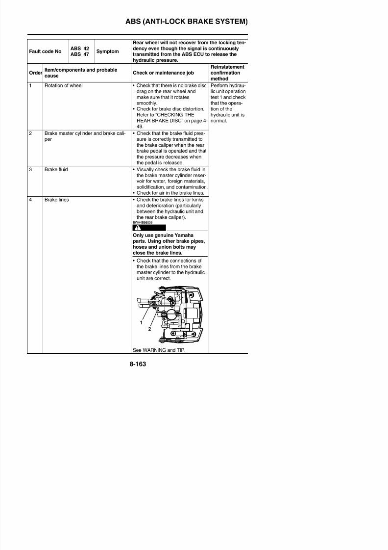
8/21/2019 Fz8 - Service Manual
http://slidepdf.com/reader/full/fz8-service-manual 558/609
WARNING
EWA4B56002
The rear brake will not function properly if the connections are reversed.• Brake pipe/joint assembly “1” inlet: from the rear brake master cylinder
• Brake pipe/joint assembly “2” outlet: to the rear brake caliper
TIP
• If the brake pipe inlet and outlet connections are reversed on the hydraulic unit, the rear brakepedal will be pressed down to its full-stroke position without responding, and then it will be pushedback slowly without pulsating when the final check on page “[D-3] FINAL CHECK” on page 8-174 is performed.
• If the front and rear brake pipe connections are reversed on the hydraulic unit, the pulsating actionin the front brake lever and rear brake pedal will be performed in the reverse order when the finalcheck on page “[D-3] FINAL CHECK” on page 8-174 is performed.
p p p
correctly and securely. Check thehydraulic unit operation.Refer to “HYDRAULIC UNITOPERATION TESTS” on page 4-60.
ABS (ANTI-LOCK BRAKE SYSTEM)
Fault code No. ABS_43 SymptomIncorrect signal from the front wheel sensor is
detected.
OrderItem/components and probablecause
Check or maintenance jobReinstatementconfirmation
method1 Installed condition of wheel sensor. Check for looseness. Repair or
replace the wheel sensor if nec-essary.
• Turn the mainswitch to “ON”and checkthat the ABSwarning lightcomes on for2 seconds,
2 Installed condition of wheel bearings,axle, sensor housing, and sensorrotor.
Check the components for loose-ness, distortion, and bends.Refer to “CHECKING THEFRONT WHEEL” on page 4-14
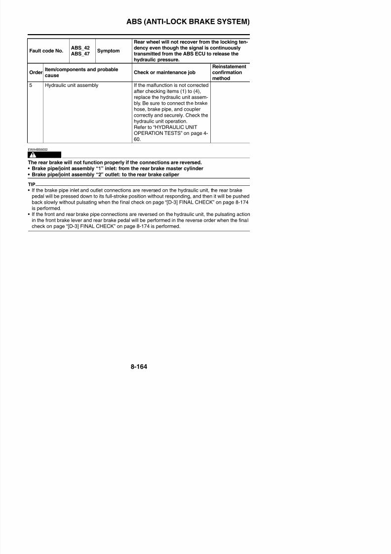
8/21/2019 Fz8 - Service Manual
http://slidepdf.com/reader/full/fz8-service-manual 559/609
seco ds,
then goes off.• Perform a trial
run at a con-
stant speed of30 km/h andcheck that theABS warninglight does not
come on.
FRONT WHEEL on page 4 14.
3 Foreign material inside sensor hous-ing.
Check the interior of the sensorhousing and the surface of thesensor rotor for foreign material,such as metal particles. Clean thesensor housing and sensor rotorif necessary.Refer to “MAINTENANCE OFTHE FRONT WHEEL SENSORAND SENSOR ROTOR” on page4-15.
4 Defective sensor rotor. • Check the surface of the sensorrotor for damage.
• If there is visible damage,replace the sensor rotor.
ABS (ANTI-LOCK BRAKE SYSTEM)
Fault code No. ABS_44 SymptomIncorrect signal from the rear wheel sensor is
detected.
OrderItem/components and probablecause
Check or maintenance jobReinstatementconfirmation
method1 Installed condition of wheel sensor. Check for looseness. Repair or
replace the wheel sensor if nec-essary.
• Turn the mainswitch to “ON”and checkthat the ABSwarning lightcomes on for2 seconds,
2 Installed condition of wheel bearings,axle, sensor housing, and sensorrotor.
Check the components for loose-ness, distortion, and bends.Refer to “CHECKING THE REARWHEEL” on page 4-24.
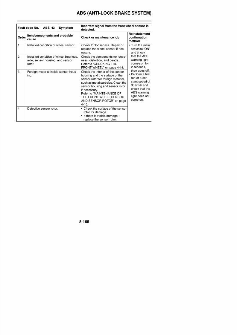
8/21/2019 Fz8 - Service Manual
http://slidepdf.com/reader/full/fz8-service-manual 560/609
,
then goes off.• Perform a trial
run at a con-
stant speed of30 km/h andcheck that theABS warninglight does not
come on.
WHEEL on page 4 24.
3 Foreign material inside sensor hous-ing.
Check the interior of the sensorhousing and the surface of thesensor rotor for foreign material,such as metal particles. Clean thesensor housing and sensor rotorif necessary.Refer to “MAINTENANCE OFTHE REAR WHEEL SENSORAND SENSOR ROTOR” on page4-25.
4 Defective sensor rotor. • Check the surface of the sensorrotor for damage.
• If there is visible damage,replace the sensor rotor.
Fault code No. ABS_51ABS_52
Symptom Power voltage is too high.
OrderItem/components and probablecause
Check or maintenance jobReinstatementconfirmationmethod
1 Battery voltage Replace the battery.Refer to “CHECKING ANDCHARGING THE BATTERY” on
page 8-186.
• Turn the mainswitch to “ON”and check
that the ABSwarning lightcomes on for
2 Disconnected battery terminal (faultcode No ABS 52)
Check the connection. Replace orreconnect the terminal if neces-
ABS (ANTI-LOCK BRAKE SYSTEM)
Fault code No. ABS_53 Symptom Power voltage is too low.
OrderItem/components and probablecause
Check or maintenance jobReinstatementconfirmationmethod
1 Battery voltage Recharge or replace the battery.Refer to “CHECKING ANDCHARGING THE BATTERY” onpage 8-186.
• Turn the mainswitch to “ON”and checkthat the ABSwarning lightcomes on for2 seconds,then goes off.
2 Connections• ABS ECU coupler
• Check the coupler for any pinsthat may be pulled out.
• Check the locking condition ofthe coupler.
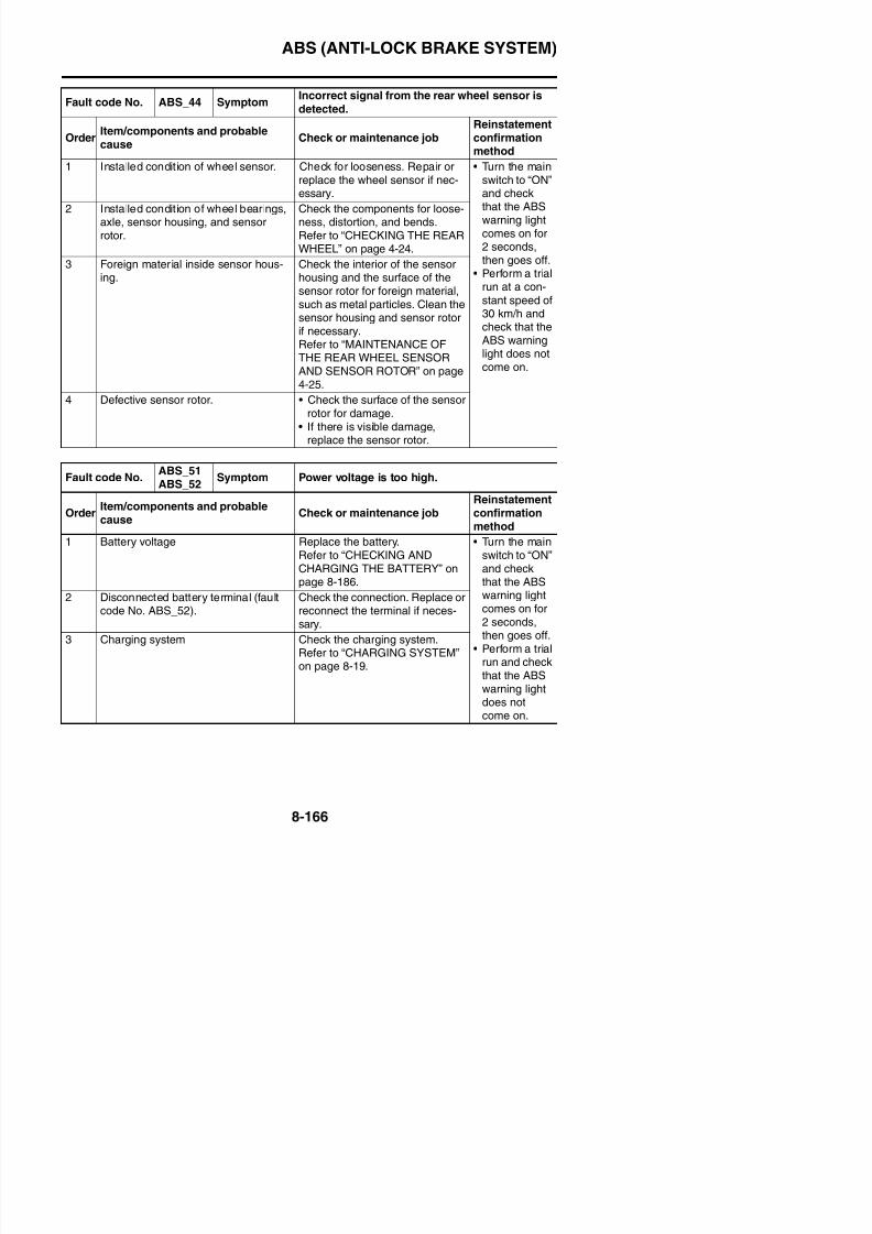
8/21/2019 Fz8 - Service Manual
http://slidepdf.com/reader/full/fz8-service-manual 561/609
• Perform a trialrun and checkthat the ABS
warning lightdoes notcome on.
p
• If there is a malfunction, repair itand connect the couplersecurely.
TIP
Turn the main switch to “OFF”before disconnecting or connect-ing a coupler.
3 Open or short circuit in wire harness. • Repair or replace if there is anopen or short circuit.
• Between ABS ECU coupler andABS ECU fuse.(Brown/White–Brown/White)
4 Charging system Check the charging system.Refer to “CHARGING SYSTEM”on page 8-19.
ABS (ANTI-LOCK BRAKE SYSTEM)
Fault code No. ABS_54 Symptom Power voltage is too low.
OrderItem/components and probablecause
Check or maintenance jobReinstatementconfirmationmethod
1 Battery voltage Recharge or replace the battery.Refer to “CHECKING ANDCHARGING THE BATTERY” onpage 8-186.
• Turn the mainswitch to “ON”and checkthat the ABSwarning lightcomes on for2 seconds,then goes off.
2 Connections• ABS ECU coupler• Starter relay coupler
• Check the coupler for any pinsthat may be pulled out.
• Check the locking condition ofthe coupler.
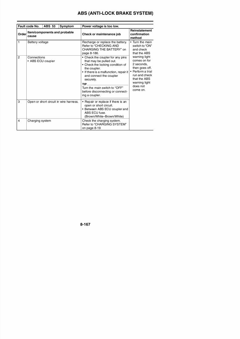
8/21/2019 Fz8 - Service Manual
http://slidepdf.com/reader/full/fz8-service-manual 562/609
• Perform a trialrun and checkthat the ABS
warning lightdoes notcome on.
• If there is a malfunction, repair itand connect the couplersecurely.
TIP
Turn the main switch to “OFF”before disconnecting or connect-ing a coupler.
3 Open or short circuit in wire harness. • Repair or replace if there is anopen or short circuit.
• Between ABS ECU coupler andABS ECU fuse.(Brown/white–Brown/white)
• Between ABS ECU coupler andABS solenoid fuse.
(Red–Red)
• Between ABS ECU coupler andABS motor fuse.(Red/black–Red/black)
4 Charging system Check the charging system.Refer to “CHARGING SYSTEM”on page 8-19.
ABS (ANTI-LOCK BRAKE SYSTEM)
Fault code No. ABS_56 SymptomHydraulic unit sensor power monitor circuit is
abnormal.
OrderItem/components and probablecause
Check or maintenance jobReinstatementconfirmation
method1 Defective internal monitor circuit (sen-
sor power).Replace the hydraulic unit assem-bly.
• Turn the mainswitch to “ON”and checkthat the ABSwarning lightcomes on for2 seconds,
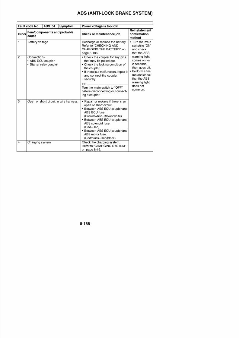
8/21/2019 Fz8 - Service Manual
http://slidepdf.com/reader/full/fz8-service-manual 563/609
then goes off.• Perform
hydraulic unit
operation test1 and checkthat the oper-ation of thehydraulic unit
is normal.
ABS (ANTI-LOCK BRAKE SYSTEM)
Fault code No. ABS_63 Symptom Front wheel sensor power is abnormal.
OrderItem/components and probablecause
Check or maintenance jobReinstatementconfirmationmethod
1 Short circuit in wire harness. • Check that there is no short cir-cuit between the blue terminal“1” and the green terminal “2”.
• Check that there is no short cir-cuit between the frame groundand the green terminal “2”.
• If there is a short circuit, thewire harness is defective. Prop-
Turn the mainswitch to “ON”and check thatthe ABS warn-ing light comeson for 2 sec-onds, then goesoff.
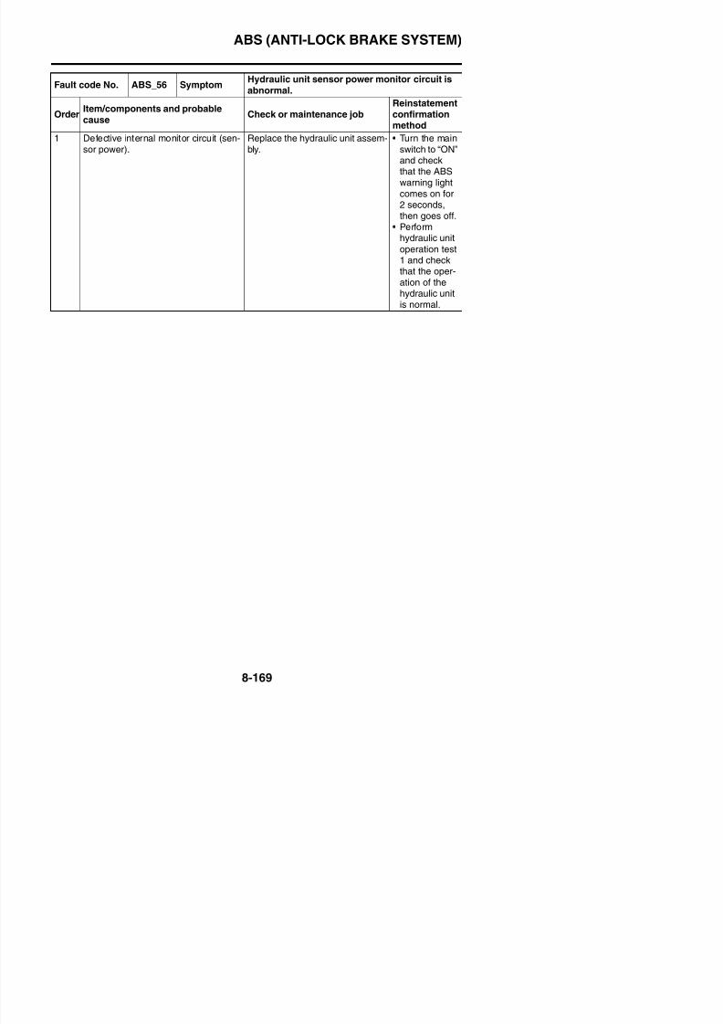
8/21/2019 Fz8 - Service Manual
http://slidepdf.com/reader/full/fz8-service-manual 564/609
erly repair or replace the wireharness.
TIP
Disconnect the ABS ECU couplerbefore checking the wire harness.
2 Short circuit in front wheel sensorlead.
• Check that there is no short cir-cuit between the white terminal
“3” and the gray terminal “4”.• Check that there is no short cir-
cuit between the frame groundand the white terminal “3”.
• If there is a short circuit, thefront wheel sensor is defective.Properly repair or replace thefront wheel sensor.
5. ABS ECU
ABS (ANTI-LOCK BRAKE SYSTEM)
Fault code No. ABS_64 Symptom Rear wheel sensor power is abnormal.
OrderItem/components and probablecause
Check or maintenance jobReinstatementconfirmationmethod
1 Short circuit in wire harness. • Check that there is no short cir-cuit between the white/red ter-minal “1” and the white terminal“2”.
• Check that there is no short cir-cuit between the frame groundand the white terminal “2”.
• If there is a short circuit, the
Turn the mainswitch to “ON”and check thatthe ABS warn-ing light comeson for 2 sec-onds, then goesoff.
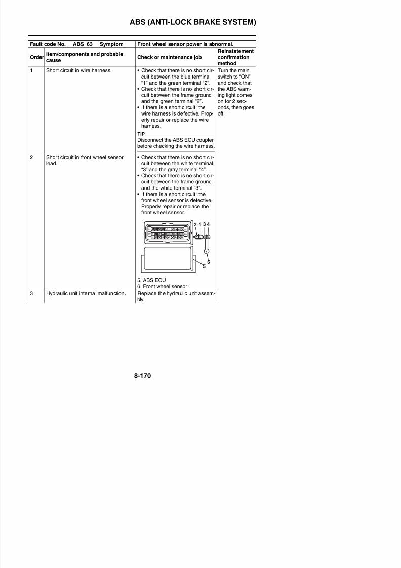
8/21/2019 Fz8 - Service Manual
http://slidepdf.com/reader/full/fz8-service-manual 565/609
wire harness is defective. Prop-erly repair or replace the wireharness.
TIP
Disconnect the ABS ECU couplerbefore checking the wire harness.
2 Short circuit in rear wheel sensor lead. • Check that there is no short cir-
cuit between the white terminal“3” and the gray terminal “4”.
• Check that there is no short cir-cuit between the frame groundand the white terminal “3”.
• If there is a short circuit, therear wheel sensor is defective.Properly repair or replace the
rear wheel sensor.
ABS (ANTI-LOCK BRAKE SYSTEM)
EAS4B56023
[D-1] DELETING THE FAULT CODESECA4B56026
Since the fault codes remain in the memory
of the ABS ECU until they are deleted,always delete the fault codes after the ser-vice has been completed.
1. Connect the test coupler adapter “1” to theABS test coupler “2”. Refer to “[B-5] MAL-FUNCTION ARE CURRENTLYDETECTED” on page 8-140.
5. The multi-function display switches to theodometer/tripmeter/fuel reserve tripmeterdisplay and the ABS warning light flashes
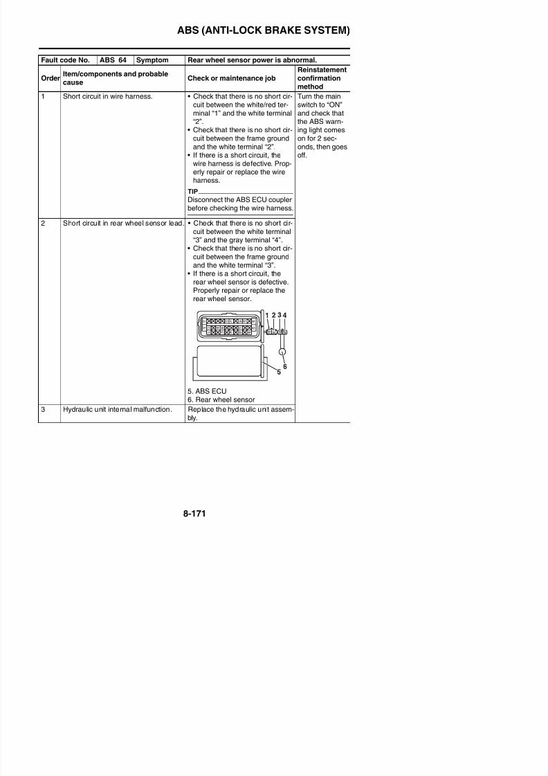
8/21/2019 Fz8 - Service Manual
http://slidepdf.com/reader/full/fz8-service-manual 566/609
2. Turn the main switch to “ON”.Fault codes will be displayed in the multi-function display.
3. Set the engine stop switch “1” to “ ”.ECA4B56025
If the start switch is pushed without settingthe engine stop switch to “ ”, the starter
in 0.5 second-intervals while the faultcodes are being deleted.
6. Turn the main switch to “OFF”.7. Turn the main switch to “ON” again.
TIP
If fault codes are still displayed in the multi-function display, the malfunctions have not
been repaired. Diagnose the malfunctionsusing the fault codes.
8. Turn the main switch to “OFF”.9. Disconnect the test coupler adapter from
the ABS test coupler, and then install theprotective cap onto the ABS test coupler.Deleting the fault codes is now finished.
TIPDo not forget to install the protective cap ontothe ABS test coupler.
EAS4B56025
[D-2] DELETE FUNCTION TEST1. Place the vehicle on the sidestand.2. Turn the main switch to “OFF”.
3. Connect the test coupler adapter to theABS test coupler.4. Turn the main switch to “ON”.
ABS (ANTI-LOCK BRAKE SYSTEM)
a. Connect the digital circuit tester (DC 20 V)to the ABS ECU coupler.
b. Check for continuity between the ABS ECUand the start switch lead.
Digital circuit tester
90890-03174Model 88 Multimeter withtachometer
YU-A1927
• Positive tester probe →
Brown/white “1”• Negative tester probe →
Bl k “2”
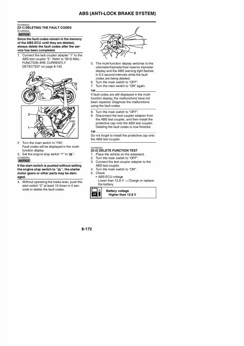
8/21/2019 Fz8 - Service Manual
http://slidepdf.com/reader/full/fz8-service-manual 567/609
b. Measure the ABS ECU voltage.
6. Check:• ABS-ECU-to-start-switch-lead continuity
No continuity → Replace or repair thewire harness.
a. Connect the digital circuit tester to the ABSECU coupler and right handlebar switch
coupler.
7. Check:• ABS ECU voltage
Out of specification → Replace the righthandlebar switch.
a. Connect the digital circuit tester (DC 12 V)to the ABS ECU coupler.
Black “2”
Continuity is all right.
Digital circuit tester90890 03174
Start switch “ON”: less than 1 VStart switch “OFF”: more than12 V
Digital circuit tester90890-03174
Model 88 Multimeter with
tachometerYU-A1927
• Positive tester probe →White/blue “1”
• Negative tester probe →
Black “2”
ABS (ANTI-LOCK BRAKE SYSTEM)
EAS4B56024
[D-3] FINAL CHECK
Checking procedures1. Check the brake fluid level in the brake master cylinder reservoir.
Refer to “CHECKING THE BRAKE FLUID LEVEL” on page 3-14.2. Check the wheel sensor housings and wheel sensors for proper installation.Refer to “INSTALLING THE FRONT WHEEL (FRONT BRAKE DISCS)” on page 4-19 and“INSTALLING THE REAR WHEEL (REAR BRAKE DISC)” on page 4-28.
3. Perform hydraulic unit operation test 1 or 2.Refer to “HYDRAULIC UNIT OPERATION TESTS” on page 4-60.
4. Delete the fault codes.Refer to “[D-1] DELETING THE FAULT CODES” on page 8-172.
5 Perform a trial run
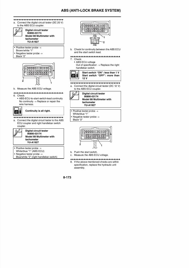
8/21/2019 Fz8 - Service Manual
http://slidepdf.com/reader/full/fz8-service-manual 568/609
5. Perform a trial run.Refer to “TRIAL RUN” on page 4-63.
ELECTRICAL COMPONENTS
EAS27973
ELECTRICAL COMPONENTS
8/21/2019 Fz8 - Service Manual
http://slidepdf.com/reader/full/fz8-service-manual 569/609
ELECTRICAL COMPONENTS
1. Main switch
2. Immobilizer unit
3. Front brake light switch
4. Clutch switch
5. Ignition coil
6. Fuse box 2
7. Main fuse
8. Battery
9. Fuse box 1
10.Fuel injection system fuse
11.Starter relay
12.Rear brake light switch
13.O2 sensor
14 Sidestand switch
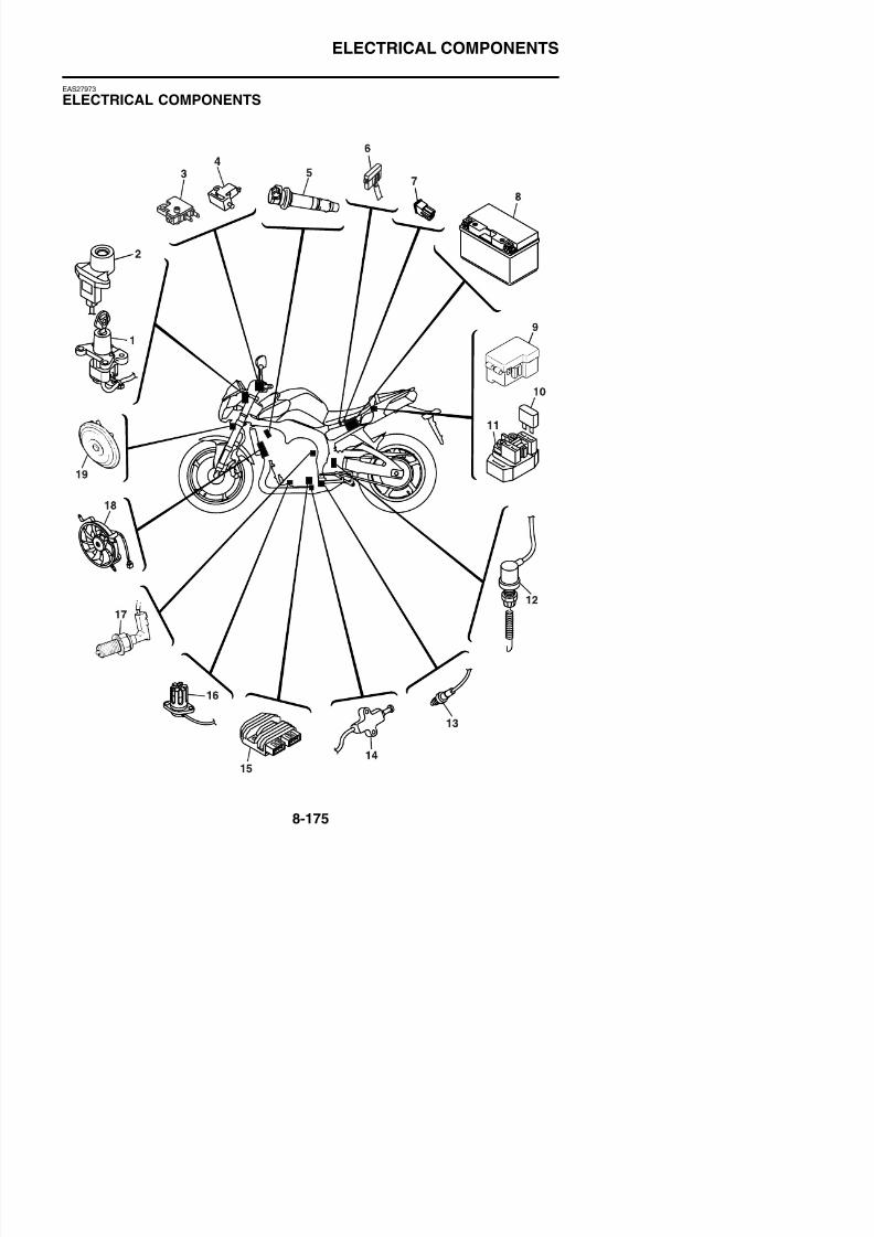
8/21/2019 Fz8 - Service Manual
http://slidepdf.com/reader/full/fz8-service-manual 570/609
14.Sidestand switch
15.Rectifier/regulator
16.Oil level switch
17.Neutral switch
18.Radiator fan motor
19.Horn
ELECTRICAL COMPONENTS
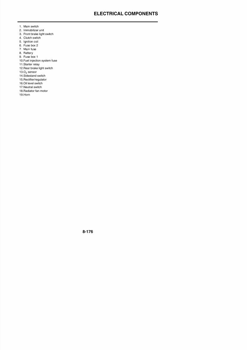
8/21/2019 Fz8 - Service Manual
http://slidepdf.com/reader/full/fz8-service-manual 571/609
ELECTRICAL COMPONENTS
1. Intake air temperature sensor
2. ECU (engine control unit)
3. Intake air pressure sensor
4. Fuel pump
5. Atmospheric pressure sensor
6. Relay unit
7. Lean angle sensor
8. Turn signal/hazard relay
9. Headlight relay
10.Radiator fan motor relay
11.Rear wheel sensor
12.Coolant temperature sensor
13.Crankshaft position sensor
14.Sub-throttle servo motor
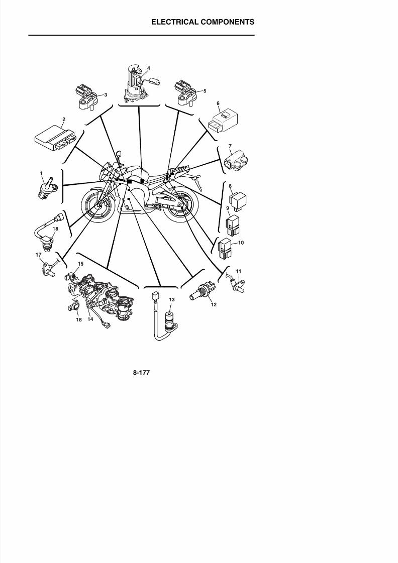
8/21/2019 Fz8 - Service Manual
http://slidepdf.com/reader/full/fz8-service-manual 572/609
15.Sub-throttle position sensor
16.Throttle position sensor
17.Front wheel sensor
18.Cylinder identification sensor
ELECTRICAL COMPONENTS
EAS27981
CHECKING THE SWITCHES
8/21/2019 Fz8 - Service Manual
http://slidepdf.com/reader/full/fz8-service-manual 573/609
ELECTRICAL COMPONENTS
FZ8NA1. Clutch switch
2. Pass switch
3. Dimmer switch
4. Hazard switch
5. Turn signal switch6. Horn switch
7. Main switch
8. Oil level switch
9. Sidestand switch
10.Front brake light switch
11.Engine stop switch
12.Start switch
13.Neutral switch14 Rear brake light switch
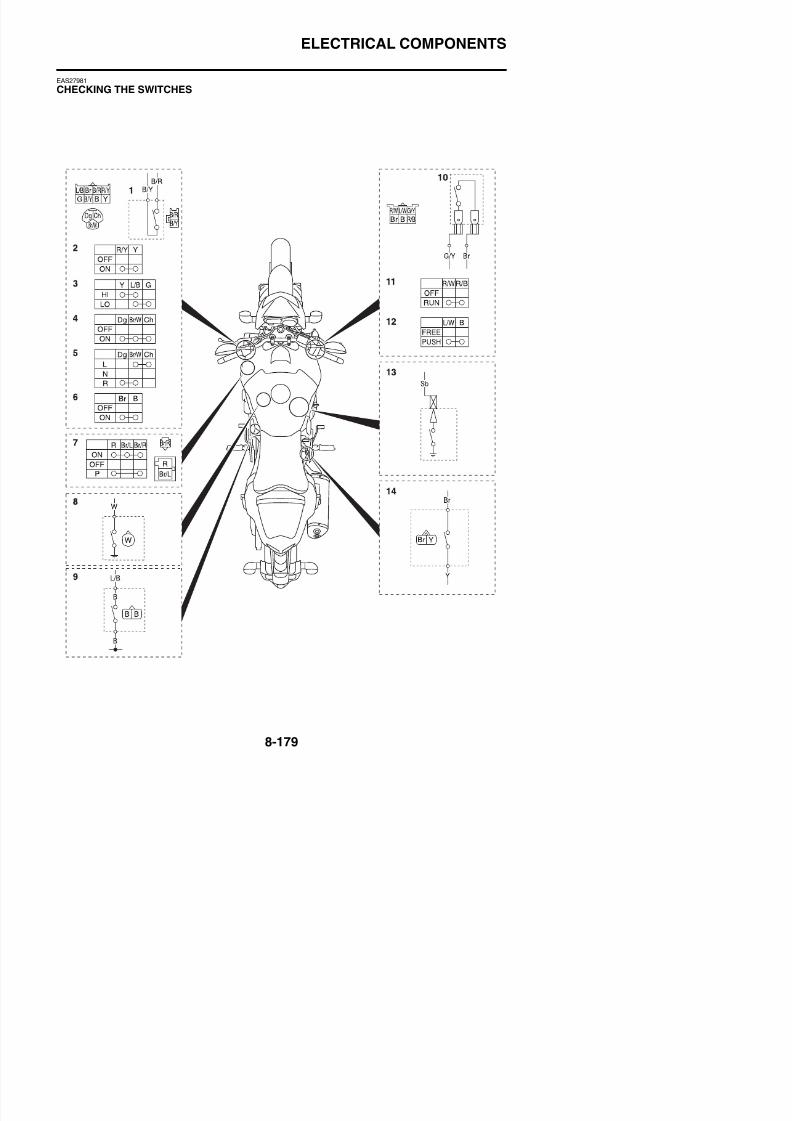
8/21/2019 Fz8 - Service Manual
http://slidepdf.com/reader/full/fz8-service-manual 574/609
14.Rear brake light switch
ELECTRICAL COMPONENTS

8/21/2019 Fz8 - Service Manual
http://slidepdf.com/reader/full/fz8-service-manual 575/609
ELECTRICAL COMPONENTS
FZ8SA1. Clutch switch
2. Pass switch
3. Dimmer switch
4. Hazard switch
5. Turn signal switch6. Horn switch
7. Main switch
8. Oil level switch
9. Sidestand switch
10.Front brake light switch
11.Engine stop switch
12.Start switch
13.Neutral switch14 Rear brake light switch
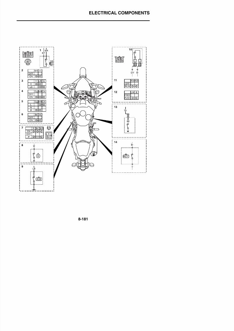
8/21/2019 Fz8 - Service Manual
http://slidepdf.com/reader/full/fz8-service-manual 576/609
14.Rear brake light switch
ELECTRICAL COMPONENTS
Check each switch for continuity with the pocket tester. If the continuity reading is incorrect, checkthe wiring connections and if necessary, replace the switch.ECA14370
Never insert the tester probes into the coupler terminal slots “a”. Always insert the probes
from the opposite end of the coupler, taking care not to loosen or damage the leads.
TIP
• Before checking for continuity, set the pocket tester to “0” and to the “Ω × 1” range.• When checking for continuity switch back and forth between the switch positions a few times
Pocket tester90890-03112
Analog pocket testerYU-03112-C

8/21/2019 Fz8 - Service Manual
http://slidepdf.com/reader/full/fz8-service-manual 577/609
When checking for continuity, switch back and forth between the switch positions a few times.
The switches and their terminal connections are illustrated as in the following example of the mainswitch.The switch positions “a” are shown in the far left column and the switch lead colors “b” are shown inthe top row.The continuity (i. e., a closed circuit) between switch terminals at a given switch position is indicated
by “ ”.
There is continuity between red, brown/blue and brown/red when the switch is set to “ON”.There is continuity between red and brown/red when the switch is set to “P”.
ELECTRICAL COMPONENTS
EAS27990
CHECKING THE BULBS AND BULB SOCK-ETSCheck each bulb and bulb socket for damageor wear, proper connections, and also for conti-
nuity between the terminals.Damage/wear → Repair or replace the bulb,bulb socket or both.
Improperly connected → Properly connect.No continuity → Repair or replace the bulb,bulb socket or both.
Types of bulbsThe bulbs used on this vehicle are shown inthe illustration.
B lb “ ” i d f th h dli ht d
Checking the condition of the bulbsThe following procedure applies to all of thebulbs.1. Remove:
• Bulb
WARNING
EWA13320
Since the headlight bulb gets extremely
hot, keep flammable products and yourhands away from the bulb until it hascooled down.
ECA14380
• Be sure to hold the socket firmly wheni th b lb N ll th l d
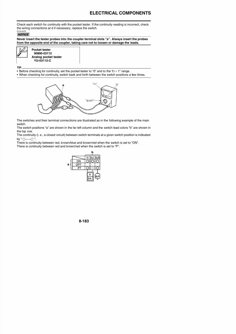
8/21/2019 Fz8 - Service Manual
http://slidepdf.com/reader/full/fz8-service-manual 578/609
• Bulbs “a” is used for the headlights and usu-ally use a bulb holder that must be detachedbefore removing the bulb. The majority ofthese types of bulbs can be removed fromtheir respective socket by turning them coun-terclockwise.
• Bulbs “b” and “c” are used for turn signal andtail/brake lights and can be removed from thesocket by pushing and turning the bulb coun-terclockwise.
• Bulbs “d” is used for meter and indicator
lights and can be removed from their respec-tive socket by carefully pulling them out.
removing the bulb. Never pull the lead,otherwise it may be pulled out of the ter-minal in the coupler.
• Avoid touching the glass part of the head-light bulb to keep it free from oil, other-wise the transparency of the glass, thelife of the bulb, and the luminous flux willbe adversely affected. If the headlightbulb gets soiled, thoroughly it with a clothmoistened with alcohol or lacquer thin-ner.
2. Check:• Bulb (for continuity)
(with the pocket tester)
No continuity→
Replace.
TIP
Before checking for continuity, set the pocket
tester to “0” and to the “Ω × 1” range.
Pocket tester90890-03112
Analog pocket testerYU-03112-C
ELECTRICAL COMPONENTS
Checking the condition of the bulb socketsThe following procedure applies to all of thebulb sockets.
1. Check:• Bulb socket (for continuity)
a. Connect the pocket tester to the fuse andcheck the continuity.
TIP
Set the pocket tester selector to “Ω × 1”.
b. If the pocket tester indicates “∞”, replacethe fuse.
3 R l
Pocket tester90890-03112
Analog pocket testerYU-03112-C
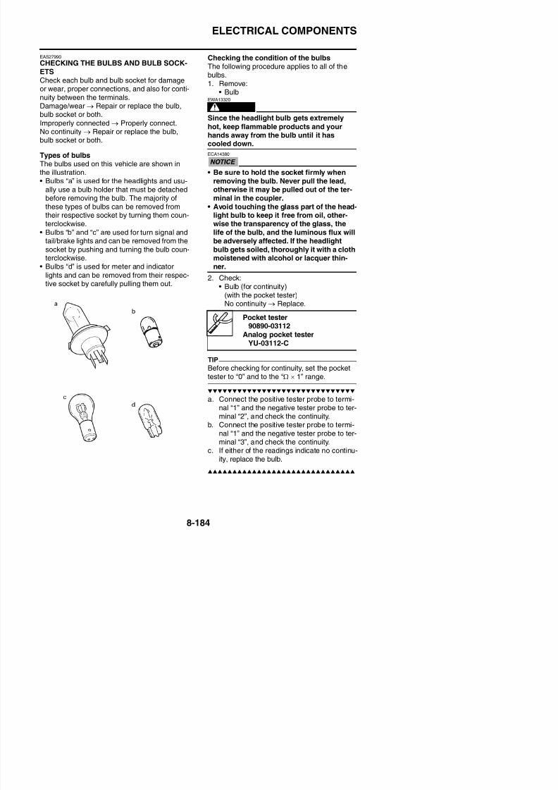
8/21/2019 Fz8 - Service Manual
http://slidepdf.com/reader/full/fz8-service-manual 579/609
• Bulb socket (for continuity)(with the pocket tester)
No continuity → Replace.
TIP
Check each bulb socket for continuity in thesame manner as described in the bulb section;however, note the following.
a. Install a good bulb into the bulb socket.
b. Connect the pocket tester probes to therespective leads of the bulb socket.
c. Check the bulb socket for continuity. If anyof the readings indicate no continuity,replace the bulb socket.
EAS28000
CHECKING THE FUSESThe following procedure applies to all of thef
3. Replace:• Blown fuse
a. Set the main switch to “OFF”.b. Install a new fuse of the correct amperage
rating.c. Set on the switches to verify if the electrical
circuit is operational.d. If the fuse immediately blows again, check
the electrical circuit.
Pocket tester90890-03112
Analog pocket tester
YU-03112-C
FusesAmperage
ratingQ’ty
Main 50 A 1
Headlight 15 A 1
Signaling system 10 A 1
Ignition 15 A 1
Taillight 10 A 1
Backup 10 A 1
Fuel injection system 15 A 1
Radiator fan motor 10 A 2
ABS motor 30 A 1
ABS solenoid 20 A 1
ABS control unit 7.5 A 1
ELECTRICAL COMPONENTS
ignition systems to malfunction and couldpossibly cause a fire.
4. Install:
• Rider seatRefer to “GENERAL CHASSIS” on page4-1.
EAS28031
CHECKING AND CHARGING THE BATTERY
WARNING
EWA13290
Batteries generate explosive hydrogen gas
and contain electrolyte which is made ofpoisonous and highly caustic sulfuric acid.
appropriate charging method. If the bat-tery is overcharged, the electrolyte levelwill drop considerably. Therefore, takespecial care when charging the battery.
TIPSince VRLA (Valve Regulated Lead Acid) bat-teries are sealed, it is not possible to check the
charge state of the battery by measuring thespecific gravity of the electrolyte. Therefore,the charge of the battery has to be checked bymeasuring the voltage at the battery terminals.
1. Remove:
• Rider seatRefer to “GENERAL CHASSIS” on page
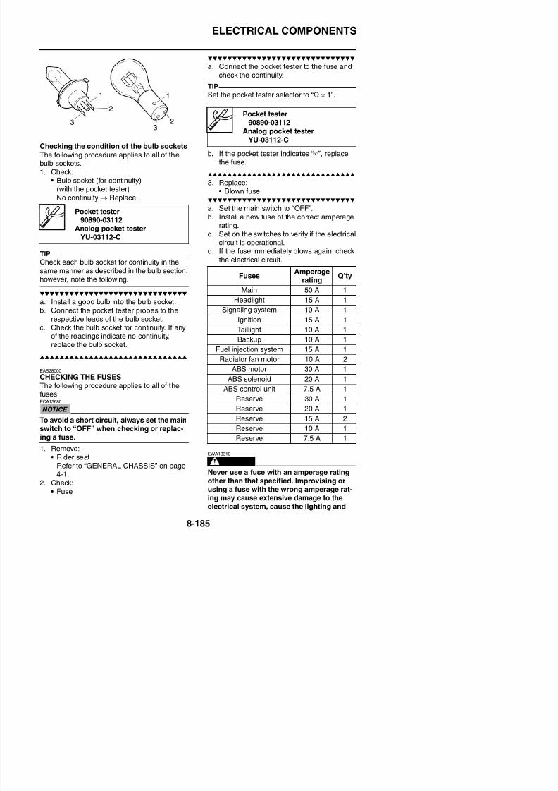
8/21/2019 Fz8 - Service Manual
http://slidepdf.com/reader/full/fz8-service-manual 580/609
po so ous a d g y caus c su u c ac dTherefore, always follow these preventivemeasures:• Wear protective eye gear when handling
or working near batteries.• Charge batteries in a well-ventilated area.• Keep batteries away from fire, sparks or
open flames (e.g., welding equipment,lighted cigarettes).
• DO NOT SMOKE when charging or han-dling batteries.
• KEEP BATTERIES AND ELECTROLYTEOUT OF REACH OF CHILDREN.
• Avoid bodily contact with electrolyte as itcan cause severe burns or permanent eye
injury.FIRST AID IN CASE OF BODILY CONTACT:EXTERNAL• Skin — Wash with water.
• Eyes — Flush with water for 15 minutesand get immediate medical attention.
INTERNAL• Drink large quantities of water or milk fol-
lowed with milk of magnesia, beaten eggor vegetable oil. Get immediate medicalattention
Refer to GENERAL CHASSIS on page4-1.
2. Disconnect:• Battery leads
(from the battery terminals)ECA13640
First, disconnect the negative battery lead“1”, and then positive battery lead “2”.
3. Remove:
• BatteryRefer to “GENERAL CHASSIS” on page
4-1.4. Check:• Battery charge
ELECTRICAL COMPONENTS
voltage when the positive battery terminal isdisconnected).
• No charging is necessary when the open-cir-cuit voltage equals or exceeds 12.8 V.
b. Check the charge of the battery, as shownin the charts and the following example.
WARNING
EWA13300
Do not quick charge a battery.
ECA13671
• Do not use a high-rate battery chargersince it forces a high-amperage currentinto the battery quickly and can causebattery overheating and battery platedamage.
• If it is impossible to regulate the charging
current on the battery charger, be carefulnot to overcharge the battery.
• When charging a battery, be sure toremove it from the vehicle (If charging
ExampleOpen-circuit voltage = 12.0 VCharging time = 6.5 hoursCharge of the battery = 20–30%
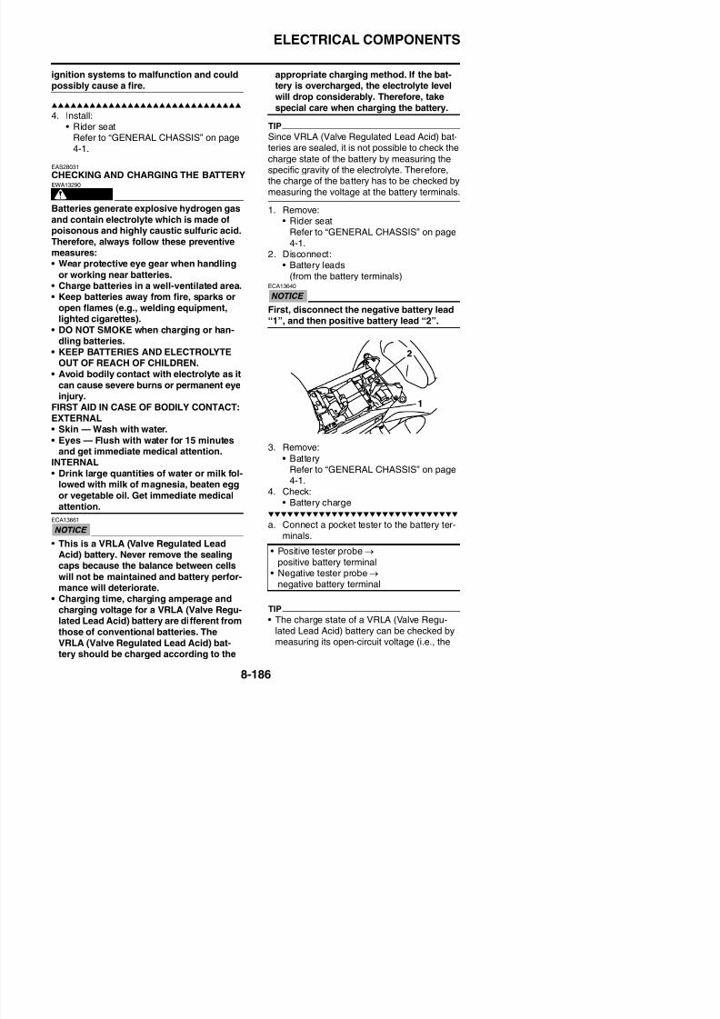
8/21/2019 Fz8 - Service Manual
http://slidepdf.com/reader/full/fz8-service-manual 581/609
remove it from the vehicle. (If charginghas to be done with the battery mountedon the vehicle, disconnect the negativebattery lead from the battery terminal.)
• To reduce the chance of sparks, do notplug in the battery charger until the bat-tery charger leads are connected to the
battery.• Before removing the battery charger lead
clips from the battery terminals, be sureto turn off the battery charger.
• Make sure the battery charger lead clipsare in full contact with the battery termi-nal and that they are not shorted. A cor-roded battery charger lead clip may
generate heat in the contact area and aweak clip spring may cause sparks.
• If the battery becomes hot to the touch atany time during the charging process,disconnect the battery charger and let thebattery cool before reconnecting it. Hotbatteries can explode!
• As shown in the following illustration, the
open-circuit voltage of a VRLA (ValveRegulated Lead Acid) battery stabilizes
A. Open-circuit voltage (V)
B. Charging time (hours)
C. Relationship between the open-circuit volt-age and the charging time at 20 °C (68 °F)
D. These values vary with the temperature,the condition of the battery plates, and theelectrolyte level.
A Open circ it oltage (V)
ELECTRICAL COMPONENTS
f. If charging requires more than 5 hours, it isadvisable to check the charging currentafter a lapse of 5 hours. If there is anychange in the amperage, readjust the volt-age to obtain the standard charging cur-
rent.g. Measure the battery open-circuit voltage
after leaving the battery unused for morethan 30 minutes.
A. Open-circuit voltage (V)
B. Time (minutes)
C. Charging
D. Ambient temperature 20 °C (68 °F)E. Check the open-circuit voltage.
12.8 V or more --- Charging is complete.
12.7 V or less --- Recharging is required.Under 12.0 V --- Replace the battery.
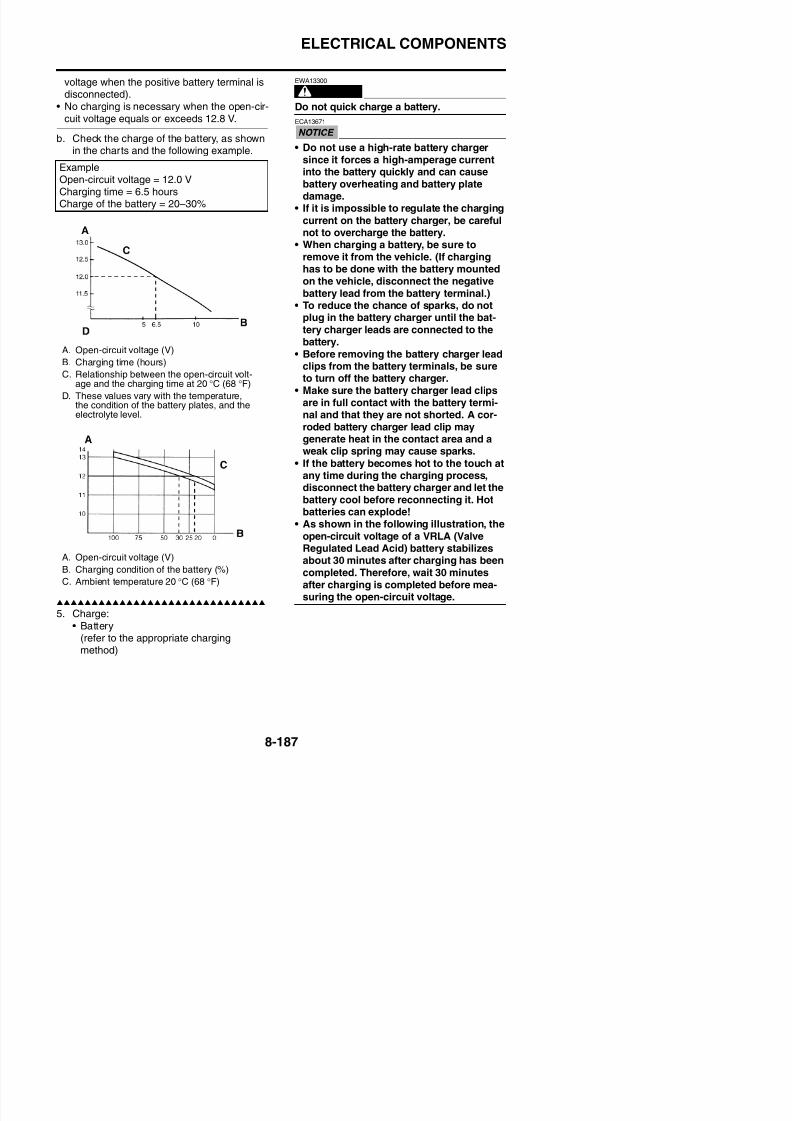
8/21/2019 Fz8 - Service Manual
http://slidepdf.com/reader/full/fz8-service-manual 582/609
Charging method using a variable-current(voltage) chargera. Measure the open-circuit voltage prior to
charging.
TIP
Voltage should be measured 30 minutes afterthe engine is stopped.
b. Connect a charger and ammeter to the bat-tery and start charging.
TIP
Set the charging voltage to 16–17 V. If the set-ting is lower, charging will be insufficient. If toohigh, the battery will be over-charged.
c. Make sure that the current is higher thanthe standard charging current written onthe battery.
TIP
If the current is lower than the standard charg-ing current written on the battery, set thecharging voltage adjust dial at 20–24 V and
Charging method using a constant voltagechargera. Measure the open-circuit voltage prior to
charging.
TIP
Voltage should be measured 30 minutes afterthe engine is stopped.
b. Connect a charger and ammeter to the bat-tery and start charging.
c. Make sure that the current is higher thanthe standard charging current written onthe battery.
TIPIf the current is lower than the standard charg-ing current written on the battery, this type ofbattery charger cannot charge the VRLA(Valve Regulated Lead Acid) battery. A vari-able voltage charger is recommended.
d. Charge the battery until the battery’s charg-
ing voltage is 15 V.TIP
S t th h i ti t 20 h ( i )
ELECTRICAL COMPONENTS
7. Connect:• Battery leads
(to the battery terminals)ECA13630
First, connect the positive battery lead “1”,and then the negative battery lead “2”.
Starter relay
1. Positive battery terminal
2. Negative battery terminal
3. Positive tester probe
4. Negative tester probe
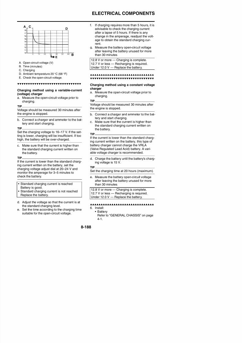
8/21/2019 Fz8 - Service Manual
http://slidepdf.com/reader/full/fz8-service-manual 583/609
8. Check:• Battery terminals
Dirt → Clean with a wire brush.Loose connection → Connect properly.
9. Lubricate:• Battery terminals
10. Install:• Rider seat
Refer to “GENERAL CHASSIS” on page4-1.
EAS28040
CHECKING THE RELAYSCheck each switch for continuity with thepocket tester. If the continuity reading is incor-rect, replace the relay.
Relay unit (starting circuit cut-off relay)
Recommended lubricantDielectric grease
Pocket tester90890-03112
Analog pocket tester
g p
Relay operationContinuity
(between “3” and “4”)
1. Positive battery terminal
2. Negative battery terminal
3. Positive tester probe
4. Negative tester probe
Result
Continuity(between “3” and “4”)
ELECTRICAL COMPONENTS
Relay unit (fuel pump relay) Radiator fan motor relay
1. Positive battery terminal
2. Negative battery terminal
3. Positive tester probe
4. Negative tester probe
1. Positive battery terminal
2. Negative battery terminal3. Positive tester probe
4 N ti t t b
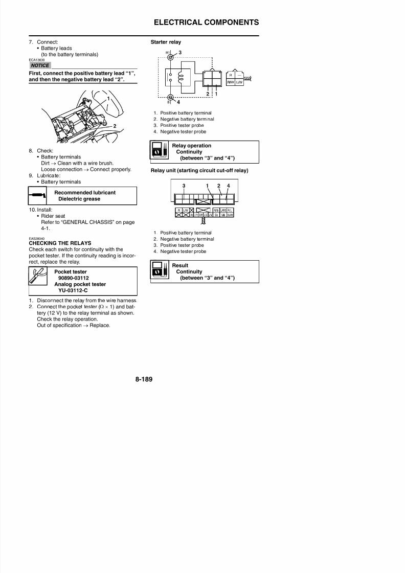
8/21/2019 Fz8 - Service Manual
http://slidepdf.com/reader/full/fz8-service-manual 584/609
Headlight relay
EAS39P1801
CHECKING THE TURN SIGNAL/HAZARDRELAY1. Check:
• Turn signal/hazard relay input voltageOut of specification → The wiring circuitfrom the main switch to the turn signal/ hazard relay coupler is faulty and must be
repaired.
a. Connect the pocket tester (DC 20 V) to theturn signal/hazard relay terminal as shown.
ResultContinuity
(between “3” and “4”)
1. Positive battery terminal
2. Negative battery terminal
3. Positive tester probe
4. Negative tester probe
ResultContinuity
(between “3” and “4”)
4. Negative tester probe
ResultContinuity
(between “3” and “4”)
Turn signal/hazard relay inputvoltage
DC 12 V
Pocket tester90890-03112
ELECTRICAL COMPONENTS
b. Turn the main switch to “ON”.c. Measure the turn signal/hazard relay input
voltage.
2 Ch k
EAS28050
CHECKING THE RELAY UNIT (DIODE)1. Check:
• Relay unit (diode)Out of specification → Replace.
TIP
The pocket tester or the analog pocket testerreadings are shown in the following table.
Pocket tester90890-03112
Analog pocket testerYU-03112-C
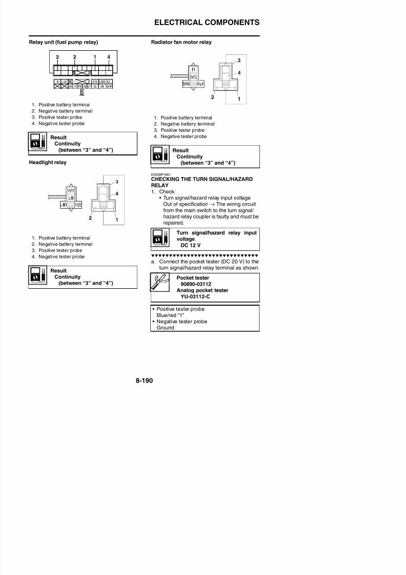
8/21/2019 Fz8 - Service Manual
http://slidepdf.com/reader/full/fz8-service-manual 585/609
2. Check:• Turn signal/hazard relay output voltage
Out of specification → Replace.
a. Connect the pocket tester (DC 20 V) to theturn signal/hazard relay terminal as shown.
Turn signal/hazard relay outputvoltage
DC 12 V
Pocket tester90890-03112
Analog pocket tester
YU-03112-C
• Positive tester probeBrown/white “1”
• Negative tester probeGround
ELECTRICAL COMPONENTS
a. Disconnect the relay unit coupler from thewire harness.
b. Connect the pocket tester (Ω × 1) to therelay unit terminal as shown.
c. Check the relay unit (diode) for continuity.d. Check the relay unit (diode) for no continu-
ity.
EAS28100
CHECKING THE IGNITION COILSThe following procedure applies to all of the
ignition coils.1. Check:
• Primary coil resistance
ContinuityPositive tester probeSky blue “1”Negative tester probeYellow/black “2”
No continuityPositive tester probe
Yellow/black “2”Negative tester probeSky blue “1”
ContinuityPositive tester probeSky blue “1”Negative tester probeBlue/yellow “3”
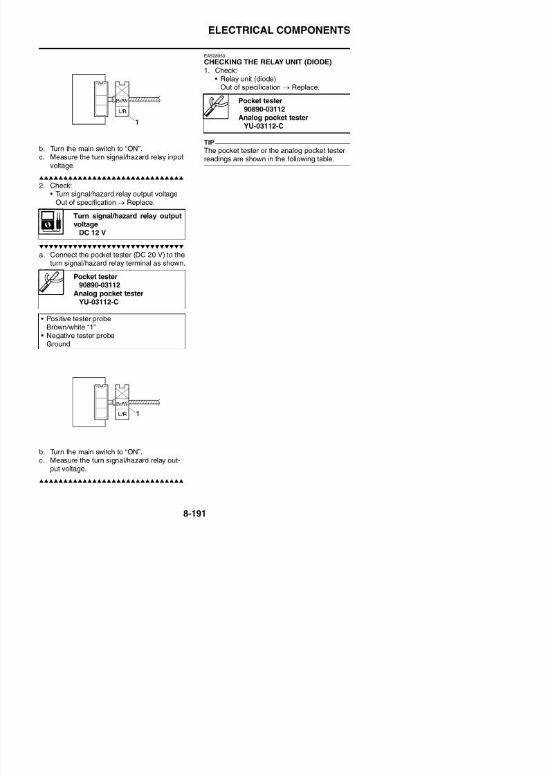
8/21/2019 Fz8 - Service Manual
http://slidepdf.com/reader/full/fz8-service-manual 586/609
yOut of specification → Replace.
a. Disconnect the ignition coil connectorsfrom the ignition coil terminals.
b. Connect the pocket tester (Ω × 1) to theignition coil as shown.
No continuityPositive tester probeBlue/yellow “3”Negative tester probeSky blue “1”
ContinuityPositive tester probe
Sky blue “1”Negative tester probeSky blue/white “4”
No continuityPositive tester probeSky blue/white “4”Negative tester probeSky blue “1”
ContinuityPositive tester probeBlue/black “5”Negative tester probeBlue/yellow “3”
No continuityPositive tester probeBlue/yellow “3”Negative tester probe
Primary coil resistance1.19–1.61 Ω
Pocket tester90890-03112
Analog pocket tester
YU-03112-C
• Positive tester probeRed/black “1”
• Negative tester probeOrange or Gray/red or Orange/green orGray/green “2”
ELECTRICAL COMPONENTS
2. Check:• Secondary coil resistance
Out of specification → Replace.
a. Connect the pocket tester (Ω × 1 k) to theignition coil as shown.
b. Set the main switch to “ON” and enginestop switch to “ ”.
c. Measure the ignition spark gap “a”.
Secondary coil resistance
8.50–11.50 k Ω
Pocket tester90890-03112
Analog pocket tester
YU-03112-C
• Negative tester probe
2. Ignition coil
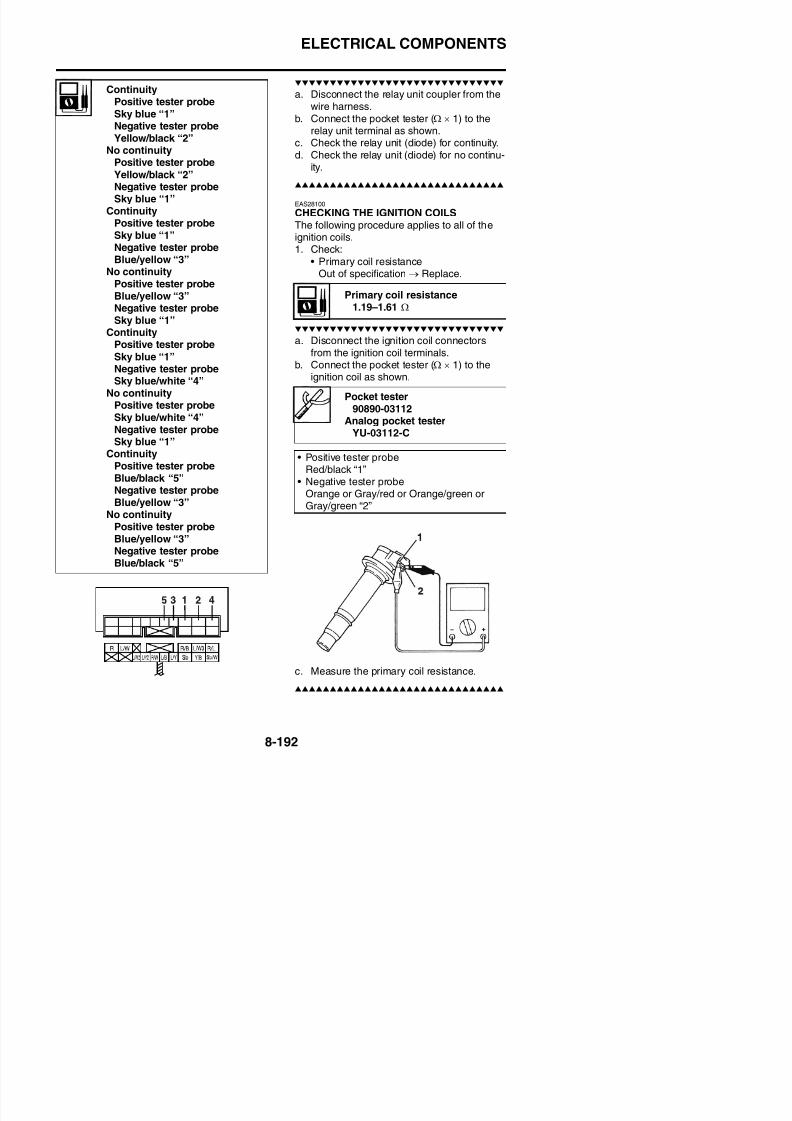
8/21/2019 Fz8 - Service Manual
http://slidepdf.com/reader/full/fz8-service-manual 587/609
b. Measure the secondary coil resistance.
3. Check:• Ignition spark gap
Out of specification → Replace.
d. Crank the engine by pushing the starterswitch and gradually increase the sparkgap until a misfire occurs.
EAS28120
CHECKING THE CRANKSHAFT POSITIONSENSOR1. Disconnect:
• Crankshaft position sensor coupler
(from the wire harness)2. Check:
• Crankshaft position sensor resistanceOut of specification → Replace the crank-
shaft position sensor.
a. Connect the pocket tester (Ω × 100) to thecrankshaft position sensor coupler asshown.
• Negative tester probeRed/black “1”
• Positive tester probe
Spark plug terminal “2”
Minimum ignition spark gap6.0 mm (0.24 in)
Crankshaft position sensorresistance
336–504 Ω at 20 °C (68 °F)
ELECTRICAL COMPONENTS
b. Measure the crankshaft position sensor
resistance.
EAS28131
CHECKING THE LEAN ANGLE SENSOR1. Remove:
• Lean angle sensor
c. Set the main switch to “ON”.d. When turn the lean angle sensor to 65°.e. Measure the lean angle sensor output volt-
age.
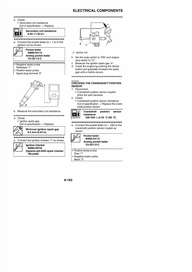
8/21/2019 Fz8 - Service Manual
http://slidepdf.com/reader/full/fz8-service-manual 588/609
• Lean angle sensor(from the battery box.)
2. Check:• Lean angle sensor output voltage
Out of specification → Replace.
a. Connect the test harness-lean angle sen-sor (6P) “1” to the lean angle sensor andwire harness as shown.
b. Connect the pocket tester (DC 20 V) to thetest harness-lean angle sensor (6P).
EAS28940
CHECKING THE STARTER MOTOR OPERA-TION1. Check:
• Starter motor operation
Does not operate → Perform the electricstarting system troubleshooting, startingwith step 4.
Refer to “TROUBLESHOOTING” on page8-17.
a. Connect the positive battery terminal “1”and starter motor lead “2” with a jumper
lead “3”.
WARNING
EWA13810
• A wire that is used as a jumper lead musthave at least the same capacity of the bat-tery lead, otherwise the jumper lead mayburn.
• This check is likely to produce sparks,
therefore, make sure no flammable gas orfluid is in the vicinity.
Lean angle sensor output volt-ageLess than 65°: 0.4–1.4 VMore than 65°: 3.7–4.4 V
Pocket tester90890-03112
Analog pocket tester
YU-03112-CTest harness- lean angle sensor
(6P)90890-03209YU 03209
ELECTRICAL COMPONENTS
EAS28150
CHECKING THE STATOR COIL1. Disconnect:
• Stator coil coupler(from the wire harness)
2. Check:• Stator coil resistance
Out of specification → Replace the stator
coil.
a. Connect the digital circuit tester to the sta-tor coil coupler as shown.
EAS28170
CHECKING THE RECTIFIER/REGULATOR1. Check:
• Rectifier/regulator input voltageOut of specification → Correct the statorcoil condition.Refer to “CHECKING THE STATORCOIL” on page 8-195.
a. Set the engine tachometer to the ignition
coil of cylinder #1.b. Connect the pocket tester (AC 20 V) to the
rectifier/regulator coupler as shown.
Stator coil resistance0.153–0.187 Ω at 20 °C (68 °F)(W–W)
Rectifier/regulator input voltageabove 14 V at 5000 r/min
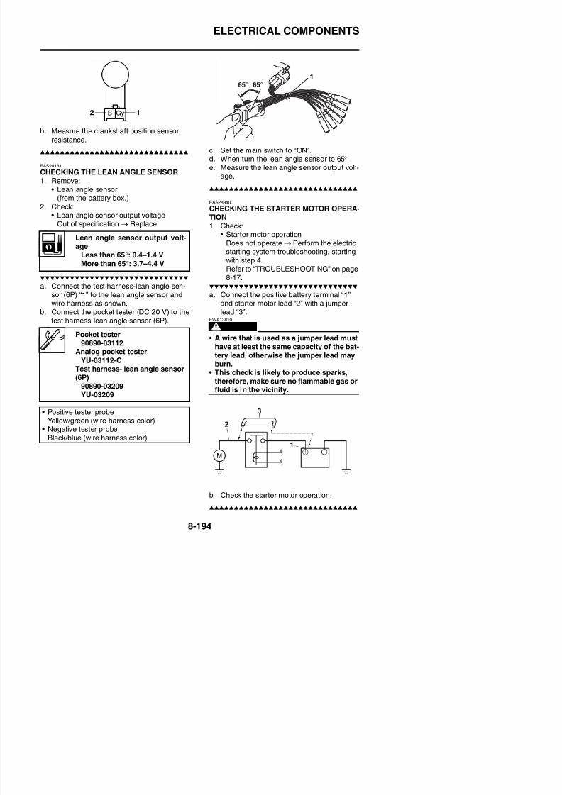
8/21/2019 Fz8 - Service Manual
http://slidepdf.com/reader/full/fz8-service-manual 589/609
g p
Digital circuit tester90890-03174
Model 88 Multimeter withtachometer
YU-A1927
• Positive tester probeWhite “1”
• Negative tester probeWhite “2”
• Positive tester probeWhite “1”
• Negative tester probeWhite “3”
• Positive tester probeWhite “2”
• Negative tester probeWhite “3”
Pocket tester90890-03112
Analog pocket testerYU-03112-C
• Positive tester probeWhite “1”
• Negative tester probeWhite “2”
• Positive tester probeWhite “1”
• Negative tester probeWhite “3”
• Positive tester probeWhite “2”
• Negative tester probeWhite “3”
ELECTRICAL COMPONENTS
2. Check:• Rectifier/regulator output voltage
Out of specification → Replace the recti-fier/regulator.
a. Set the engine tachometer to the ignitioncoil of cylinder #1.
b. Connect the pocket tester (AC 20 V) to therectifier/regulator coupler as shown.
a. Disconnect the horn leads from the hornterminals.
b. Connect the digital circuit tester to the hornterminals.
Rectifier/regulator output volt-age
14.2–14.8 V
Pocket tester90890-03112
A l k t t t
Digital circuit tester90890-03174
Model 88 Multimeter withtachometer
YU-A1927
• Positive tester probeHorn terminal “1”
• Negative tester probeHorn terminal “2”
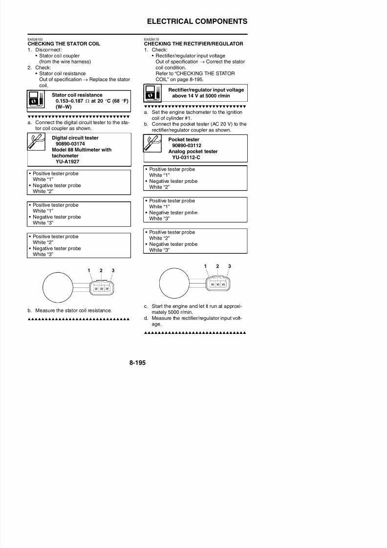
8/21/2019 Fz8 - Service Manual
http://slidepdf.com/reader/full/fz8-service-manual 590/609
c. Start the engine and let it run at approxi-mately 5000 r/min.
d. Measure the rectifier/regulator output volt-
age.
c. Measure the horn resistance.
2. Check:• Horn sound
Faulty sound → Replace.
EAS28190
CHECKING THE ENGINE OIL LEVELSWITCH1. Drain:
• Engine oil2. Remove:
• Oil level switch
Analog pocket testerYU-03112-C
• Positive tester probeRed “1”
• Negative tester probeBlack “2”
ELECTRICAL COMPONENTS
a. Connect the pocket tester (Ω × 100) to theoil level switch terminal as shown.
a. Connect the pocket tester (Ω × 10) to thefuel sender terminals as shown.
Pocket tester90890-03112
Analog pocket testerYU-03112-C
Minimum level position “A”• Positive tester probe
Connector (white) “1”• Negative tester probe
Body earth “2”
Maximum level position “B”P iti t t b
Sender unit resistance (full)19.0–21.0 Ω
Sender unit resistance (empty)139.0–141.0 Ω
Pocket tester90890-03112
Analog pocket testerYU-03112-C
• Positive tester probe →
Green/white “1”• Negative tester probe
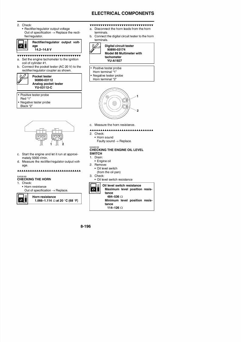
8/21/2019 Fz8 - Service Manual
http://slidepdf.com/reader/full/fz8-service-manual 591/609
b. Measure the oil level switch resistance.
EAS39P1802
CHECKING THE FUEL SENDER1. Disconnect:
• Fuel pump coupler• Fuel sender coupler
b. Measure the fuel sender resistance.
EAS29050
CHECKING THE OIL LEVEL WARNINGLIGHTThis model is equipped with a self-diagnosisdevice for the oil level detection circuit.
1. Check:• Oil level warning light “1”
(Turn the main switch to “ON”.)Warning light comes on for a few sec-onds then goes off → Warning light is
• Positive tester probeConnector (white) “1”
• Negative tester probeBody earth “2”
• Negative tester probe →
Black “2”
ELECTRICAL COMPONENTS
EAS28250
CHECKING THE RADIATOR FAN MOTORS1. Check:
• Radiator fan motor
Faulty/rough movement→
Replace.
a. Disconnect the radiator fan motor couplerfrom the wire harness
2. Check:• Coolant temperature sensor resistance
Out of specification → Replace.
a. Connect the pocket tester (Ω × 1 k/ × 100)to the coolant temperature sensor asshown.
Coolant temperature sensorresistance
2.45 k Ω at 20 °C (68 °F)290–354 Ω at 80 °C (176 °F)
Pocket tester90890-03112Analog pocket tester
YU 03112 C
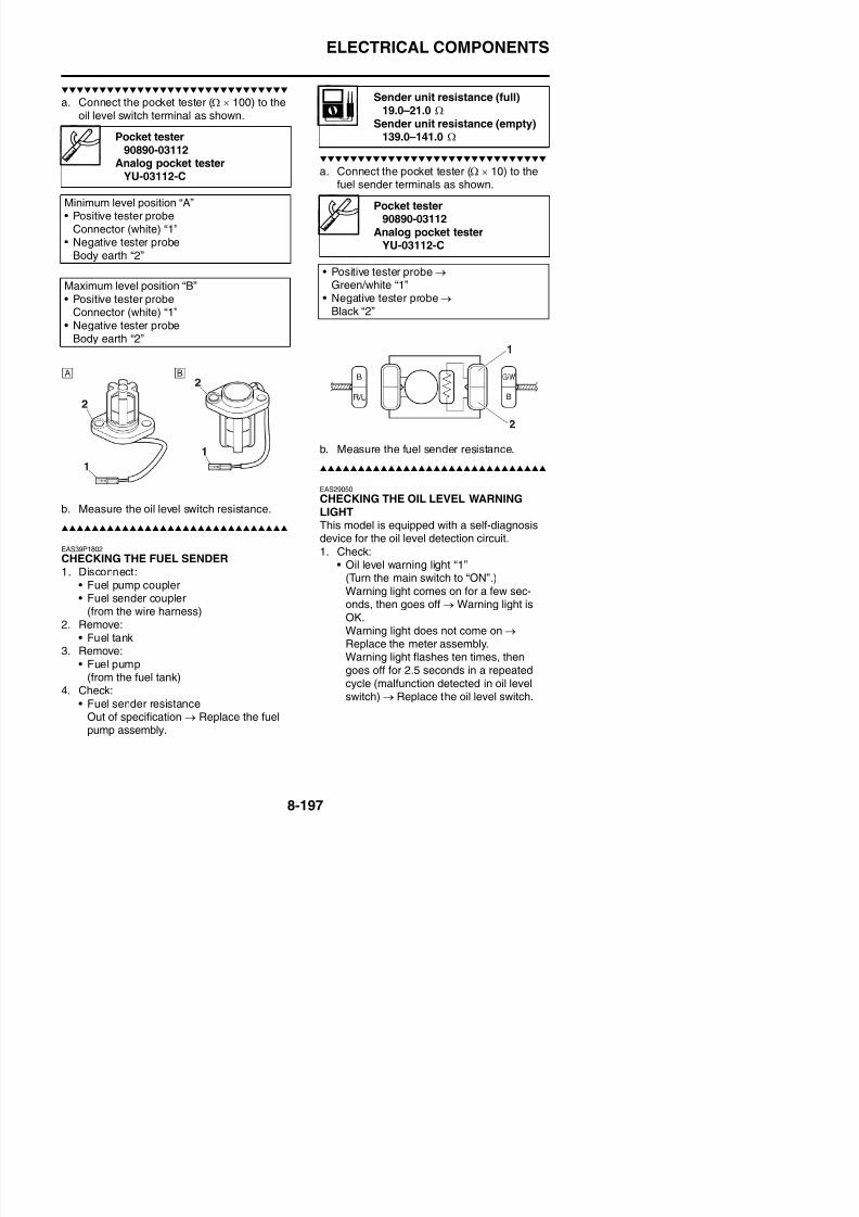
8/21/2019 Fz8 - Service Manual
http://slidepdf.com/reader/full/fz8-service-manual 592/609
from the wire harness.b. Connect the battery (DC 12 V) as shown.
c. Measure the radiator fan motor movement.
EAS28261CHECKING THE COOLANT TEMPERATURESENSOR
b. Immerse the coolant temperature sensor“1” in a container filled with coolant “2”.
TIP
Make sure the coolant temperature sensor ter-minals do not get wet.
c. Place a thermometer “3” in the coolant.
• Positive tester probeBlue “1”
• Negative tester probe
Black “2”
YU-03112-C
ELECTRICAL COMPONENTS
3. Install:• Coolant temperature sensor
EAS28300
CHECKING THE THROTTLE POSITION
SENSOR1. Remove:
• Throttle position sensor(from the throttle body)
2. Check:• Throttle position sensor
a. Connect the pocket tester (Ω × 1 k) to thethrottle position sensor as shown.
d. While slowly turning the throttle positionsensor shaft, check that the throttle posi-tion sensor resistance is within the speci-fied range.The resistance does not change or it
changes abruptly → Replace the throttleposition sensor.
3. Install:
• Throttle position sensorTIP
When installing the throttle position sensor,
Coolant temperature sensor18 Nm (1.8 m·kgf, 13 ft·lbf)
Throttle position sensor resis-tance
0–6.16 k Ω
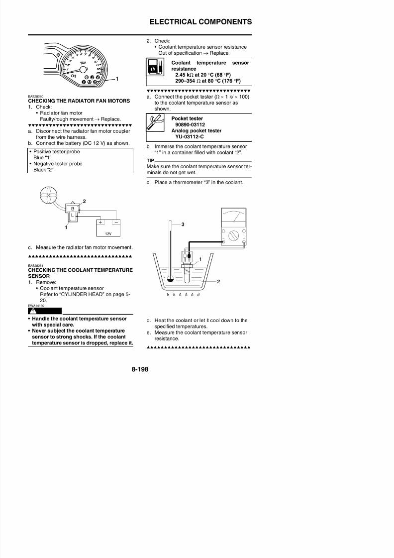
8/21/2019 Fz8 - Service Manual
http://slidepdf.com/reader/full/fz8-service-manual 593/609
p
b. Measure the throttle position sensor maxi-mum resistance.
Out of specification → Replace the throttleposition sensor.
c. Connect the pocket tester (Ω × 1 k) to thethrottle position sensor as shown.
g p ,adjust its angle properly. Refer to “ADJUST-
ING THE THROTTLE POSITION SENSOR”on page 7-11.
EAS39P1803
CHECKING THE SUB-THROTTLE POSITIONSENSOR
1. Remove:• Sub-throttle position sensor
(from the throttle body)2. Check:
• Sub-throttle position sensor
a. Connect the pocket tester (Ω × 1 k) to thesub-throttle position sensor as shown.
Pocket tester
90890-03112Analog pocket tester
YU-03112-C
• Tester positive lead →
Blue “1”• Tester negative lead →
Black/blue “2”
Throttle position sensor maxi-mum resistance
2.64–6.16 k Ω
• Tester positive lead →Yellow “3”
Pocket tester90890-03112
Analog pocket testerYU-03112-C
• Tester positive lead →Blue “1”T t ti l d
ELECTRICAL COMPONENTS
c. Connect the pocket tester (Ω × 1 k) to thesub-throttle position sensor as shown.
d. While slowly turning the sub-throttle posi-tion sensor shaft, check that the sub-throt-
a. Remove the air induction system solenoidcoupler from the air induction system sole-noid.
b. Connect the pocket tester (Ω × 1) to the air
induction system solenoid terminal asshown.
• Tester positive lead →
Green/yellow “3”• Tester negative lead →
Black/blue “2”
Pocket tester90890-03112
Analog pocket testerYU-03112-C
• Positive tester probe →
Orange “1”• Negative tester probe →
Green “2”
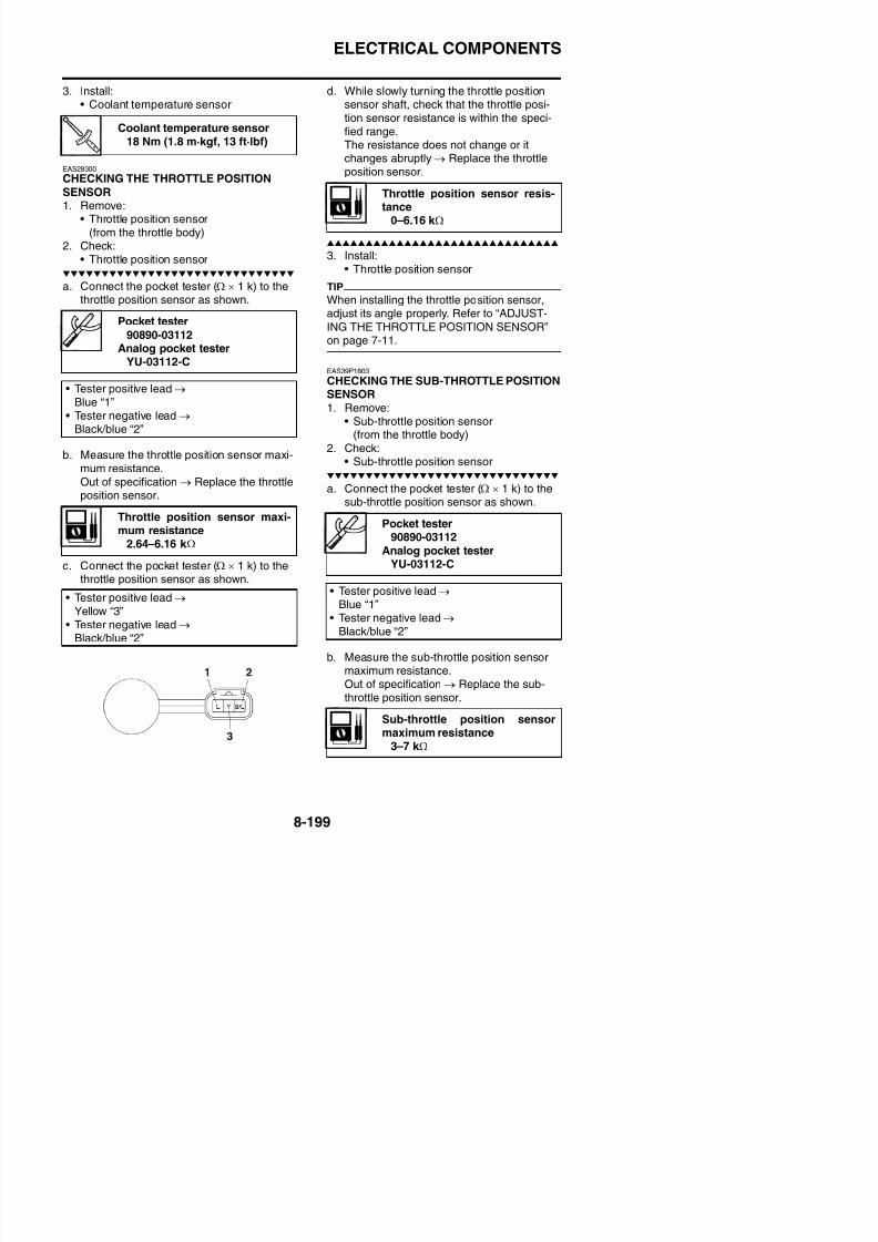
8/21/2019 Fz8 - Service Manual
http://slidepdf.com/reader/full/fz8-service-manual 594/609
tle position sensor resistance is within thespecified range.The resistance does not change or itchanges abruptly → Replace the sub-throt-tle position sensor.
TIP
Check mainly that the resistance changesgradually when turning the sub-throttle positionsensor shaft, since the readings (from closedto wide-open sub-throttle) may differ slightlyfrom those specified.
3. Install:• Sub-throttle position sensor
TIP
When installing the throttle position sensor,adjust its angle properly. Refer to “CHECKINGTHE SUB-THROTTLE POSITION SENSOR”
c. Measure the air induction system solenoidresistance.
EAS28380
CHECKING THE ATMOSPHERIC PRES-SURE SENSOR1. Check:
• Atmospheric pressure sensor output volt-age
Out of specification → Replace.
Sub-throttle position sensorresistance0–7 k Ω
Atmospheric pressure sensoroutput voltage
ELECTRICAL COMPONENTS
b. Connect the digital circuit tester (DCV) tothe test harness S-pressure sensor 5S7(3P).
b. Connect the pocket tester (DC 20 V) to thetest harness-speed sensor (3P).
Digital circuit tester90890-03174
Model 88 Multimeter withtachometer
YU-A1927Test harness S- pressure sen-sor 5S7 (3P)
90890-03211YU-03211
• Positive tester probePink (wire harness color)
• Negative tester probe
Pocket tester90890-03112
Analog pocket testerYU-03112-C
Test harness- speed sensor (3P)
90890-03208YU-03208
• Positive tester probeWhite/black (wire harness color)
• Negative tester probe
Black/blue (wire harness color)
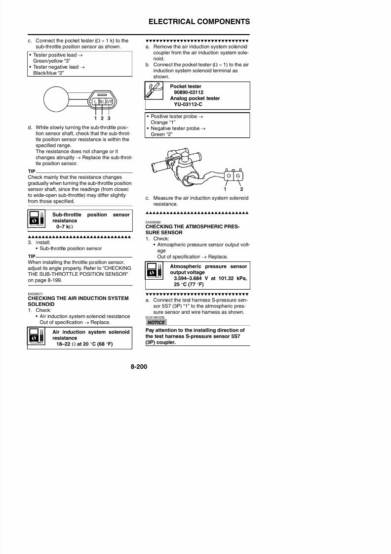
8/21/2019 Fz8 - Service Manual
http://slidepdf.com/reader/full/fz8-service-manual 595/609
c. Set the main switch to “ON”.d. Measure the atmospheric pressure sensor
output voltage.
EAS28390
CHECKING THE CYLINDER IDENTIFICA-TION SENSOR
1. Check:• Cylinder identification sensor output volt-
c. Set the main switch to “ON”.d. Rotate the crankshaft.e. Measure the voltage. With each full rotation
of the crankshaft, the voltage readingshould cycle from 0.8 V to 4.8 V to 0.8 V to
4.8 V.
EAS28411
CHECKING THE INTAKE AIR PRESSURESENSOR
1. Check:• Intake air pressure sensor output voltage
Black/blue (wire harness color)
ELECTRICAL COMPONENTS
ECA16730
Pay attention to the installing direction ofthe test harness S-pressure sensor 5S7(3P) coupler.
b. Connect the digital circuit tester (DCV) tothe test harness S-pressure sensor 5S7(3P).
2. Check:• Intake air temperature sensor resistance
Out of specification → Replace.
a. Connect the pocket tester (Ω × 1 k/ × 100)to the intake air temperature sensor termi-nal as shown.
Digital circuit tester90890-03174
Model 88 Multimeter withtachometer
YU-A1927Test harness S- pressure sen-sor 5S7 (3P)
90890-03211
Intake air temperature sensorresistance
5.40–6.60 k Ω at 0 °C (32 °F)0.29–0.39 k Ω at 80 °C (176 °F)
Pocket tester
90890-03112Analog pocket tester
YU-03112-C
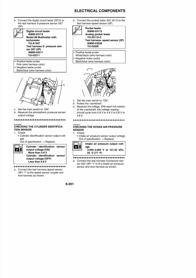
8/21/2019 Fz8 - Service Manual
http://slidepdf.com/reader/full/fz8-service-manual 596/609
c. Set the main switch to “ON”.d. Measure the intake air pressure sensor
output voltage.
b. Immerse the intake air temperature sensor“1” in a container filled with water “2”.
TIP
Make sure that the intake air temperature sen-sor terminals do not get wet.
c. Place a thermometer “3” in the water.
d. Slowly heat the water, then let it cool downto the specified temperature.
e. Measure the intake air temperature sensorresistance.
90890 03YU-03211
• Positive tester probe
Pink/white (wire harness color)
• Negative tester probeBlack/blue (wire harness color)
ELECTRICAL COMPONENTS
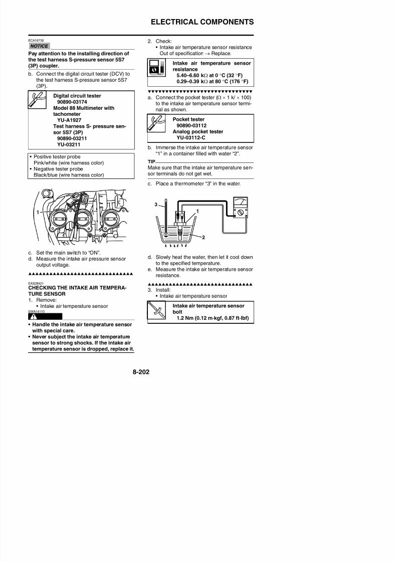
8/21/2019 Fz8 - Service Manual
http://slidepdf.com/reader/full/fz8-service-manual 597/609
TROUBLESHOOTING
TROUBLESHOOTING..................................................................................9-1GENERAL INFORMATION.....................................................................9-1
STARTING FAILURES............................................................................9-1INCORRECT ENGINE IDLING SPEED .................................................9-1POOR MEDIUM-AND-HIGH-SPEED PERFORMANCE ........................9-2FAULTY GEAR SHIFTING......................................................................9-2SHIFT PEDAL DOES NOT MOVE..........................................................9-2JUMPS OUT OF GEAR..........................................................................9-2FAULTY CLUTCH ...................................................................................9-2OVERHEATING ......................................................................................9-3
OVERCOOLING .....................................................................................9-3POOR BRAKING PERFORMANCE.......................................................9-3FAULTY FRONT FORK LEGS ................................................................9-3UNSTABLE HANDLING..........................................................................9-3
8/21/2019 Fz8 - Service Manual
http://slidepdf.com/reader/full/fz8-service-manual 598/609
FAULTY LIGHTING OR SIGNALING SYSTEM ...................................... 9-4TROUBLESHOOTING AT THE ABS WARNING LIGHT......................... 9-4
TROUBLESHOOTING
EAS28451
TROUBLESHOOTING
EAS28460
GENERAL INFORMATION
TIP
The following guide for troubleshooting doesnot cover all the possible causes of trouble. Itshould be helpful, however, as a guide to basictroubleshooting. Refer to the relative proce-dure in this manual for checks, adjustments,and replacement of parts.
EAS30410
STARTING FAILURES
Engine
1. Cylinder(s) and cylinder head(s)
Electrical system1. Battery
• Discharged battery• Faulty battery
2. Fuse(s)
• Blown, damaged or incorrect fuse• Improperly installed fuse3. Spark plug(s)
• Incorrect spark plug gap• Incorrect spark plug heat range• Fouled spark plug• Worn or damaged electrode• Worn or damaged insulator
4. Ignition coil(s)• Cracked or broken ignition coil body• Broken or shorted primary or secondary
coils
8/21/2019 Fz8 - Service Manual
http://slidepdf.com/reader/full/fz8-service-manual 599/609
1. Cylinder(s) and cylinder head(s)• Loose spark plug• Loose cylinder head or cylinder• Damaged cylinder head gasket• Damaged cylinder gasket
• Worn or damaged cylinder• Incorrect valve clearance• Improperly sealed valve• Incorrect valve-to-valve-seat contact• Incorrect valve timing• Faulty valve spring• Seized valve
2. Piston(s) and piston ring(s)
• Improperly installed piston ring• Damaged, worn or fatigued piston ring• Seized piston ring• Seized or damaged piston
3. Air fi lter• Improperly installed air filter• Clogged air filter element
4. Crankcase and crankshaft
• Improperly assembled crankcase• Seized crankshaft
5. Ignition system• Faulty ECU• Faulty crankshaft position sensor• Faulty cylinder identification sensor
• Broken pickup rotor straight key6. Switches and wiring• Faulty main switch• Faulty engine stop switch• Broken or shorted wiring• Faulty neutral switch• Faulty start switch• Faulty sidestand switch• Faulty clutch switch• Improperly grounded circuit• Loose connections
7. Starting system• Faulty starter motor• Faulty starter relay• Faulty starting circuit cut-off relay
• Faulty starter clutch
EAS30440
INCORRECT ENGINE IDLING SPEED
TROUBLESHOOTING
• Improper throttle cable free play• Flooded throttle body• Faulty air induction system
Electrical system1. Battery
• Discharged battery• Faulty battery
2. Spark plug(s)• Incorrect spark plug gap• Incorrect spark plug heat range• Fouled spark plug• Worn or damaged electrode• Worn or damaged insulator
3. Ignition coil(s)
• Broken or shorted primary or secondarycoils
• Cracked or broken ignition coil
Shift drum and shift forks• Foreign object in a shift drum groove• Seized shift fork• Bent shift fork guide bar
Transmission• Seized transmission gear• Foreign object between transmission gears• Improperly assembled transmission
EAS28550
JUMPS OUT OF GEAR
Shift shaft
• Incorrect shift pedal position• Improperly returned stopper lever
Shift forks• Worn shift fork
8/21/2019 Fz8 - Service Manual
http://slidepdf.com/reader/full/fz8-service-manual 600/609
• Cracked or broken ignition coil4. Ignition system
• Faulty ECU• Faulty crankshaft position sensor• Faulty cylinder identification sensor
• Broken pickup rotor straight key
EAS30450
POOR MEDIUM-AND-HIGH-SPEED PER-FORMANCERefer to “STARTING FAILURES” on page 9-1.
Engine1. Air fi lter
• Clogged air filter element
Fuel system1. Throttle body (-ies)
• Faulty throttle body2. Fuel pump
• Faulty fuel pump
EAS28530FAULTY GEAR SHIFTING
• Worn shift fork
Shift drum• Incorrect axial play• Worn shift drum groove
Transmission• Worn gear dog
EAS28560
FAULTY CLUTCH
Clutch slips1. Clutch
• Improperly assembled clutch• Improperly adjusted clutch cable• Loose or fatigued clutch spring• Worn friction plate• Worn clutch plate
2. Engine oil• Incorrect oil level• Incorrect oil viscosity (low)
• Deteriorated oil
Cl tch drags
TROUBLESHOOTING
2. Engine oil• Incorrect oil level• Incorrect oil viscosity (high)• Deteriorated oil
EAS30480
OVERHEATING
Engine1. Clogged coolant passages
• Cylinder head(s) and piston(s)• Heavy carbon buildup
2. Engine oil• Incorrect oil level
• Incorrect oil viscosity• Inferior oil quality
Cooling system1 Coolant
EAS28610
OVERCOOLING
Cooling system1. Thermostat
• Thermostat stays open
EAS28620
POOR BRAKING PERFORMANCE• Worn brake pad• Worn brake disc• Air in hydraulic brake system• Leaking brake fluid• Faulty brake caliper kit• Faulty brake caliper seal• Loose union bolt• Damaged brake hose• Oil or grease on the brake disc• Oil or grease on the brake pad
8/21/2019 Fz8 - Service Manual
http://slidepdf.com/reader/full/fz8-service-manual 601/609
1. Coolant• Low coolant level
2. Radiator• Damaged or leaking radiator• Faulty radiator cap• Bent or damaged radiator fin
3. Water pump• Damaged or faulty water pump• Thermostat• Thermostat stays closed• Oil cooler• Clogged or damaged oil cooler• Hose(s) and pipe(s)• Damaged hose• Improperly connected hose• Damaged pipe• Improperly connected pipe
Fuel system1. Throttle body (-ies)
• Damaged or loose throttle body joint
2. Air fi lter• Clogged air filter element
• Oil or grease on the brake pad• Incorrect brake fluid level
EAS28660
FAULTY FRONT FORK LEGS
Leaking oil• Bent, damaged or rusty inner tube• Cracked or damaged outer tube• Improperly installed oil seal• Damaged oil seal lip• Incorrect oil level (high)• Loose damper rod assembly bolt• Damaged damper rod assembly bolt copper
washer• Cracked or damaged cap bolt O-ring
Malfunction• Bent or damaged inner tube• Bent or damaged outer tube• Damaged fork spring• Worn or damaged outer tube bushing
• Bent or damaged damper rod• Incorrect oil viscosity
TROUBLESHOOTING
3. Front fork leg(s)• Uneven oil levels (both front fork legs)• Unevenly tensioned fork spring (both
front fork legs)• Broken fork spring
• Bent or damaged inner tube• Bent or damaged outer tube4. Swingarm
• Worn bearing or bushing• Bent or damaged swingarm
5. Rear shock absorber assembly(-ies)• Faulty rear shock absorber spring• Leaking oil or gas
6. Tire(s)• Uneven tire pressures (front and rear)• Incorrect tire pressure• Uneven tire wear
7 Wheel(s)
Tail/brake light does not come on• Wrong tail/brake light bulb• Too many electrical accessories• Incorrect connection• Burnt-out tail/brake light bulb
Tail/brake light bulb burnt out• Wrong tail/brake light bulb• Faulty battery• Incorrectly adjusted rear brake light switch• Tail/brake light bulb life expired
Turn signal does not come on• Faulty turn signal switch
• Faulty turn signal/hazard relay• Burnt-out turn signal bulb• Incorrect connection• Damaged or faulty wire harness
8/21/2019 Fz8 - Service Manual
http://slidepdf.com/reader/full/fz8-service-manual 602/609
7. Wheel(s)• Incorrect wheel balance• Deformed cast wheel• Damaged wheel bearing
• Bent or loose wheel axle• Excessive wheel runout
8. Frame• Bent frame• Damaged steering head pipe• Improperly installed bearing race
EAS28710
FAULTY LIGHTING OR SIGNALING SYS-
TEM
Headlight does not come on• Wrong headlight bulb• Too many electrical accessories• Hard charging• Incorrect connection• Improperly grounded circuit
• Poor contacts (main or light switch)• Burnt-out headlight bulb
g y• Improperly grounded circuit• Faulty battery• Blown, damaged or incorrect fuse
Turn signal blinks slowly• Faulty turn signal/hazard relay• Faulty main switch• Faulty turn signal switch• Incorrect turn signal bulb
Turn signal remains lit• Faulty turn signal/hazard relay
• Burnt-out turn signal bulbTurn signal blinks quickly• Incorrect turn signal bulb• Faulty turn signal/hazard relay• Burnt-out turn signal bulb
Horn does not sound• Damaged or faulty horn
• Faulty main switch• Faulty horn switch
EAS28740
WIRING DIAGRAMFZ8NA 20111. Main switch
2. Rectifier/regulator
3. AC magneto
4. Backup fuse5. Immobilizer unit
6. Main fuse
7. Frame ground
8. Engine ground
9. Battery10.Negative battery ground lead
11.Fuel injection system fuse
12.Starter relay
13.Starter motor14.Relay unit
15.Starting circuit cut-off relay16.Fuel pump relay
17 Neutral switch
56.Right handlebar switch
57.Front brake light switch
58.Engine stop switch
59.Start switch
60.Rear brake light switch
61.Left handlebar switch
62.Clutch switch63.Pass switch
64.Dimmer switch
65.Hazard switch
66.Turn signal switch
67.Horn switch
68.Horn
69.Turn signal/hazard relay
70.Rear right turn signal light
71.Rear left turn signal light72.Front right turn signal light
73.Front left turn signal light
74.Headlight
75.Auxiliary light
B/L Black/Blue
B/R Black/Red
B/W Black/White
B/Y Black/Yellow
Br/G Brown/Green
Br/L Brown/Blue
Br/R Brown/Red
Br/W Brown/White
G/B Green/Black
G/R Green/Red
G/W Green/White
G/Y Green/Yellow
Gy/B Gray/Black
Gy/G Gray/Green
Gy/R Gray/RedGy/W Gray/White
L/B Blue/Black
L/G Blue/Green
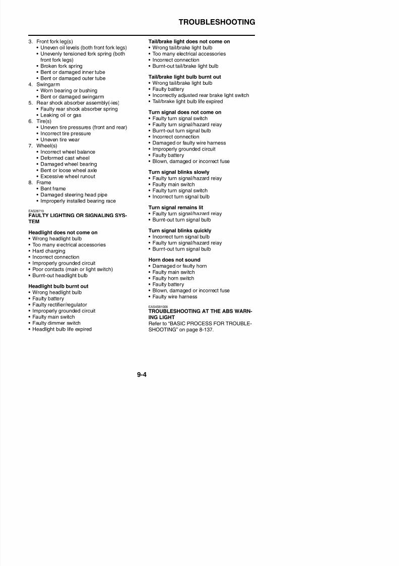
8/21/2019 Fz8 - Service Manual
http://slidepdf.com/reader/full/fz8-service-manual 603/609
17.Neutral switch
18.Sidestand switch
19.Fuel pump
20.Fuel sender
21.Lean angle sensor
22.Atmospheric pressure sensor23.Cylinder identification sensor
24.Crankshaft position sensor
25.ECU (engine control unit)
26.Ignition coil #1
27.Ignition coil #2
28.Ignition coil #3
29.Ignition coil #4
30.Spark plug
31.Injector #132.Injector #2
33.Injector #3
34.Injector #4
35.Air induction system solenoid
36.Sub-throttle servo motor
37.Sub-throttle position sensor
38.Intake air pressure sensor
39.Throttle position sensor
40.Coolant temperature sensor41.Intake air temperature sensor
42 O
y g
76.License plate light
77.Tail/brake light
78.Headlight relay (on/off)
79.Radiator fan motor relay
80.Right radiator fan motor fuse81.Right radiator fan motor
82.Left radiator fan motor fuse
83.Left radiator fan motor
84.Taillight fuse
85.Ignition fuse
86.Anti-theft alarm (OPTION)
87.Signal fuse
88.Headlight fuse
89.ABS motor fuse90.ABS solenoid fuse
91.ABS ECU fuse92.ABS ECU (electronic control
unit)
93.ABS test coupler
94.Front wheel sensor
95.Rear wheel sensor
EAS28750
COLOR CODEB Black
L/R Blue/Red
L/W Blue/White
L/Y Blue/Yellow
O/B Orange/Black
O/G Orange/GreenP/B Pink/Black
P/W Pink/White
R/B Red/Black
R/G Red/Green
R/L Red/Blue
R/W Red/White
R/Y Red/Yellow
Sb/W Sky blue/White
W/B White/Black
W/L White/Blue
W/R White/Red
W/Y White/Yellow
Y/B Yellow/Black
Y/G Yellow/Green
Y/L Yellow/Blue
Y/R Yellow/Red
Y/W Yellow/White
FZ8SA 20111. Main switch
2. Rectifier/regulator
3. AC magneto
4. Backup fuse
5. Immobilizer unit
6. Main fuse7. Frame ground
8. Engine ground
9. Battery
10.Negative battery ground lead
11.Fuel injection system fuse
12.Starter relay
13.Starter motor
14.Relay unit
15.Starting circuit cut-off relay16.Fuel pump relay
17.Neutral switch
18.Sidestand switch
19.Fuel pump
58.Engine stop switch
59.Start switch
60.Rear brake light switch
61.Left handlebar switch
62.Clutch switch
63.Pass switch
64.Dimmer switch65.Hazard switch
66.Turn signal switch
67.Horn switch
68.Horn
69.Turn signal/hazard relay
70.Rear right turn signal light
71.Rear left turn signal light
72.Front right turn signal light
73.Front left turn signal light74.Auxiliary light
75.Headlight (high beam)
76.Headlight (low beam)
77.License plate light
B/R Black/Red
B/W Black/White
B/Y Black/Yellow
Br/G Brown/Green
Br/L Brown/Blue
Br/R Brown/Red
Br/W Brown/White
G/B Green/Black
G/W Green/White
G/R Green/Red
G/Y Green/Yellow
Gy/B Gray/Black
Gy/G Gray/Green
Gy/R Gray/Red
Gy/W Gray/WhiteL/B Blue/Black
L/G Blue/Green
L/R Blue/Red
L/W Bl /Whit
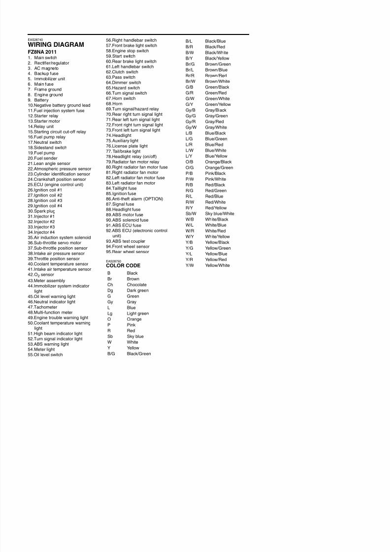
8/21/2019 Fz8 - Service Manual
http://slidepdf.com/reader/full/fz8-service-manual 604/609
p p
20.Fuel sender
21.Lean angle sensor
22.Atmospheric pressure sensor
23.Cylinder identification sensor
24.Crankshaft position sensor25.ECU (engine control unit)
26.Ignition coil #1
27.Ignition coil #2
28.Ignition coil #3
29.Ignition coil #4
30.Spark plug
31.Injector #1
32.Injector #2
33.Injector #334.Injector #4
35.Air induction system solenoid
36.Sub-throttle servo motor
37.Sub-throttle position sensor
38.Intake air pressure sensor39.Throttle position sensor
40.Coolant temperature sensor
41.Intake air temperature sensor
42.O2 sensor43.Meter assembly
44 Immobili er s stem indicator
78.Tail/brake light
79.Headlight relay (on/off)
80.Radiator fan motor relay
81.Right radiator fan motor fuse
82.Right radiator fan motor83.Left radiator fan motor fuse
84.Left radiator fan motor
85.Taillight fuse
86.Ignition fuse
87.Anti-theft alarm (OPTION)
88.Signal fuse
89.Headlight fuse
90.ABS motor fuse
91.ABS solenoid fuse
92.ABS ECU fuse
93.ABS ECU (electronic controlunit)
94.ABS test coupler
95.Front wheel sensor
96.Rear wheel sensor
EAS39P1001
COLOR CODE
B Black
Br Brown
L/W Blue/White
L/Y Blue/Yellow
O/B Orange/Black
O/G Orange/Green
P/B Pink/BlackP/W Pink/White
R/B Red/Black
R/G Red/Green
R/L Red/Blue
R/W Red/White
R/Y Red/Yellow
Sb/W Sky blue/White
W/B White/Black
W/L White/Blue
W/R White/Red
W/Y White/Yellow
Y/B Yellow/Black
Y/G Yellow/Green
Y/L Yellow/Blue
Y/R Yellow/Red
Y/W Yellow/White
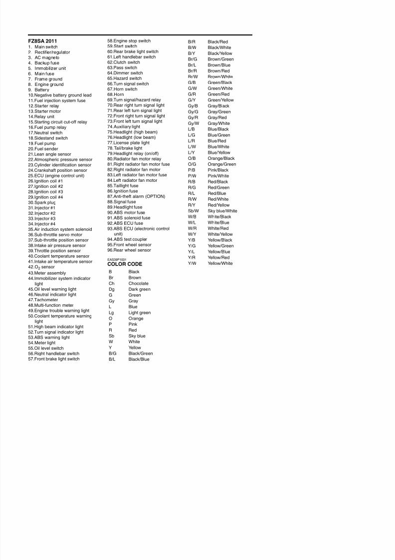
8/21/2019 Fz8 - Service Manual
http://slidepdf.com/reader/full/fz8-service-manual 605/609
WIRING DIAGRAM
FZ8NA
SCHEMA DE CABLAGE
FZ8NA
SCHALTPLAN
FZ8NA
SCHEMA ELETTRICO
FZ8NA
DIAGRAMA DE CONEXIONES
DE FZ8NA

8/21/2019 Fz8 - Service Manual
http://slidepdf.com/reader/full/fz8-service-manual 606/609
WIRING DIAGRAM
FZ8NA
SCHEMA DE CABLAGE
FZ8NA
SCHALTPLAN
FZ8NA
SCHEMA ELETTRICO
FZ8NA
DIAGRAMA DE CONEXIONES
DE FZ8NA
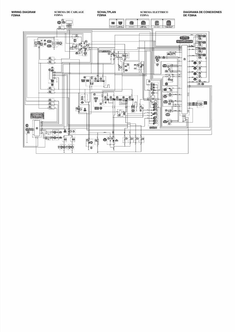
8/21/2019 Fz8 - Service Manual
http://slidepdf.com/reader/full/fz8-service-manual 607/609
WIRING DIAGRAM
FZ8SA
SCHEMA DE CABLAGE
FZ8SA
SCHALTPLAN
FZ8SA
SCHEMA ELETTRICO
FZ8SA
DIAGRAMA DE CONEXIONES
DE FZ8SA
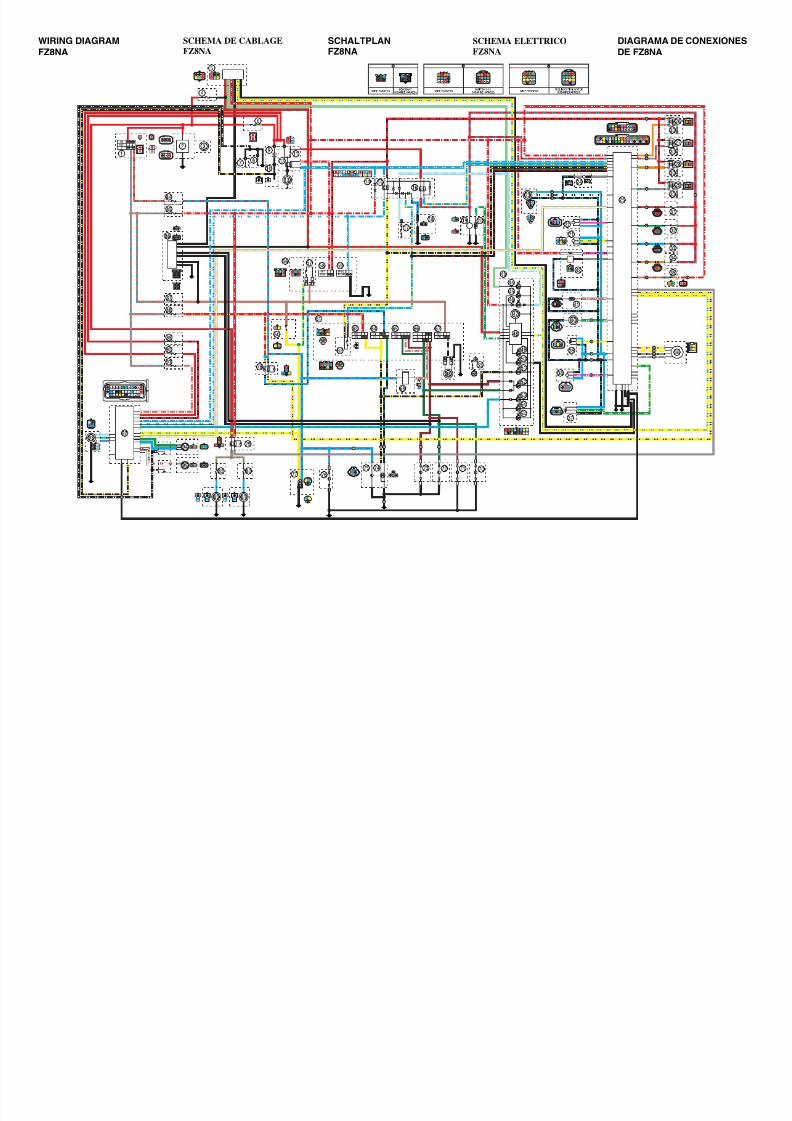
8/21/2019 Fz8 - Service Manual
http://slidepdf.com/reader/full/fz8-service-manual 608/609
WIRING DIAGRAM
FZ8SA
SCHEMA DE CABLAGE
FZ8SA
SCHALTPLAN
FZ8SA
SCHEMA ELETTRICO
FZ8SA
DIAGRAMA DE CONEXIONES
DE FZ8SA
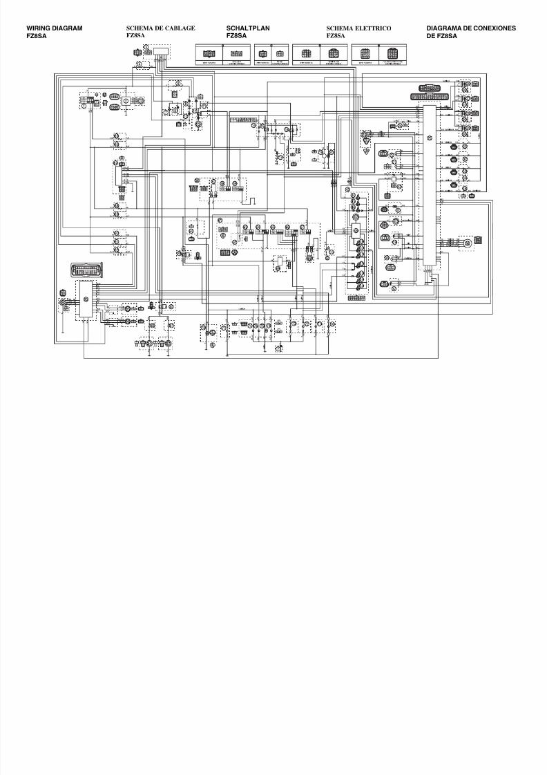
8/21/2019 Fz8 - Service Manual
http://slidepdf.com/reader/full/fz8-service-manual 609/609