fy3200sseriesfullynumericalcontrol...
TRANSCRIPT

FeelTech
FY3200S Series Fully Numerical ControlDual Channel Function/ArbitraryWaveform Generator
User’s Manual
Rev3.0 January,2016

FeelTech
FY3200S Series User’s ManualI
Guaranty and Declaration
Copyright
© 2016 FeelTech Technology Co. Ltd. All Rights Reserved.
Trademark Information
FeelTech is a registered trademark of FeelTech Technology Co. Ltd.
Declaration
FeelTech reserves the right to modify or change parts of or all the
specifications and pricing policies at company’s sole decision.
Information in this publication replaces all previously corresponding material.
FeelTech shall not be liable for losses caused by either incidental or
consequential in connection with the furnishing, use or performance of this
manual as well as any information contained.
Any part of this document is forbidden to be copied or photocopied or
rearranged without prior written approval of FeelTech。
Contact Us
If you have any problem or requirement when using our products or this
manual, please contact FeelTech.
Tel: 0086 371 68997005 E-mail:[email protected]
Website:www.feeltech.net
FeelTech
FY3200S Series User’s Manual 2
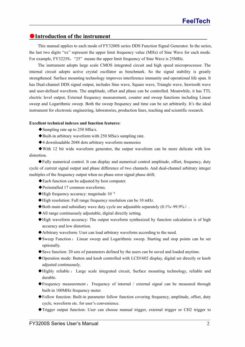
●Introduction of the instrumentThis manual applies to each mode of FY3200S series DDS Function Signal Generator. In the series,
the last two digits “xx” represent the upper limit frequency value (MHz) of Sine Wave for each mode.For example, FY3225S,“25” means the upper limit frequency of Sine Wave is 25MHz.
The instrument adopts large scale CMOS integrated circuit and high speed microprocessor. Theinternal circuit adopts active crystal oscillator as benchmark. So the signal stability is greatlystrengthened. Surface mounting technology improves interference immunity and operational life span. Ithas Dual-channel DDS signal output, includes Sine wave, Square wave, Triangle wave, Sawtooth waveand user-defined waveform. The amplitude, offset and phase can be controlled. Meanwhile, it has TTLelectric level output, External frequency measurement, counter and sweep functions including Linearsweep and Logarithmic sweep. Both the sweep frequency and time can be set arbitrarily. It’s the idealinstrument for electronic engineering, laboratories, production lines, teaching and scientific research.
Excellent technical indexes and function features:◆Sampling rate up to 250 MSa/s.◆Built-in arbitrary waveform with 250 MSa/s sampling rate.◆4 downloadable 2048 dots arbitrary waveform memories◆With 12 bit wide waveform generator, the output waveform can be more delicate with low
distortion.◆Fully numerical control. It can display and numerical control amplitude, offset, frequency, duty
cycle of current signal output and phase difference of two channels. And dual-channel arbitrary integermultiples of the frequency output when no phase error signal phase drift;
◆Each function can be adjusted by host computer.◆Preinstalled 17 common waveforms.◆High frequency accuracy: magnitude 10-6
◆High resolution: Full range frequency resolution can be 10 mHz.◆Both main and subsidiary wave duty cycle are adjustable separately (0.1%~99.9%).◆All range continuously adjustable, digital directly setting.◆High waveform accuracy: The output waveform synthesized by function calculation is of highaccuracy and low distortion.
◆Arbitrary waveform: User can load arbitrary waveform according to the need.◆Sweep Function:Linear sweep and Logarithmic sweep. Starting and stop points can be setoptionally.
◆Save function: 20 sets of parameters defined by the users can be saved and loaded anytime.◆Operation mode: Button and knob controlled with LCD1602 display, digital set directly or knobadjusted continuously.
◆Highly reliable : Large scale integrated circuit, Surface mounting technology, reliable anddurable.
◆Frequency measurement: Frequency of internal / external signal can be measured throughbuilt-in 100MHz frequency meter.
◆Follow function: Built-in parameter follow function covering frequency, amplitude, offset, dutycycle, waveform etc. for user’s convenience.
◆Trigger output function: User can choose manual trigger, external trigger or CH2 trigger to

FeelTech
FY3200S Series User’s Manual 3
control the main output to output waveforms of specified periodicity. This periodicity can also bedefined by the user.
◆FSK frequency shift keying and ASK amplitude shift keying signal output.
Product Function and Technology Indexes
Model FY3206S FY3212S FY3224S FY3225S
Sine wave frequency range 0Hz~6MHz 0Hz~12MHz 0Hz~24MHz 0Hz~25MHzSquare wave frequency range 0Hz~6MHz 0Hz~6MHz 0Hz~6MHz 0Hz~6MHzTriangle wave frequency range 0Hz~6MHz 0Hz~6MHz 0Hz~6MHz 0Hz~6MHzArbitrary wave frequency wave 0Hz~6MHz 0Hz~6MHz 0Hz~6MHz 0Hz~6MHz
Parameters of signal output
Output channel CH1 and CH2 dual channel high speed output separately.
Output waveformSine wave, square wave (duty cycle adjustable), triangle wave,sawtooth wave, arbitrary wave, common pulse, noise,electrocardiogram, AM, FM etc.
Output amplitude ≥20Vp-p(No load)Output impedance 50Ω±10%DC offset ±10VResolution 0.01Hz(10mHz)Frequency accuracy ±5×10⁻⁶
Frequency Stability ±2×10⁻⁶/3小时
Sine wave distortion ≤0.8% (reference frequency 1kHz)Triangle linearity ≥98% (0.01Hz~10kHz)Rise or fall time of square wave ≤30nsSquare wave duty cycle range 0.1%~99.9%Pulse wave width range 10nS~1S
TTL outputDual-channel TTL electric level synchronize with CH1 and CH2.Phase differences are adjustable.
Electric level range >3.3Vp-pFan-out >20 TTL (Load)Level rise fall time ≤20nsFrequency Counter functionCounter range 0-4294967295Frequency meter range 1Hz~100MHzInput Voltage Range 2Vp-p~20Vp-p
FeelTech
FY3200S Series User’s Manual 4
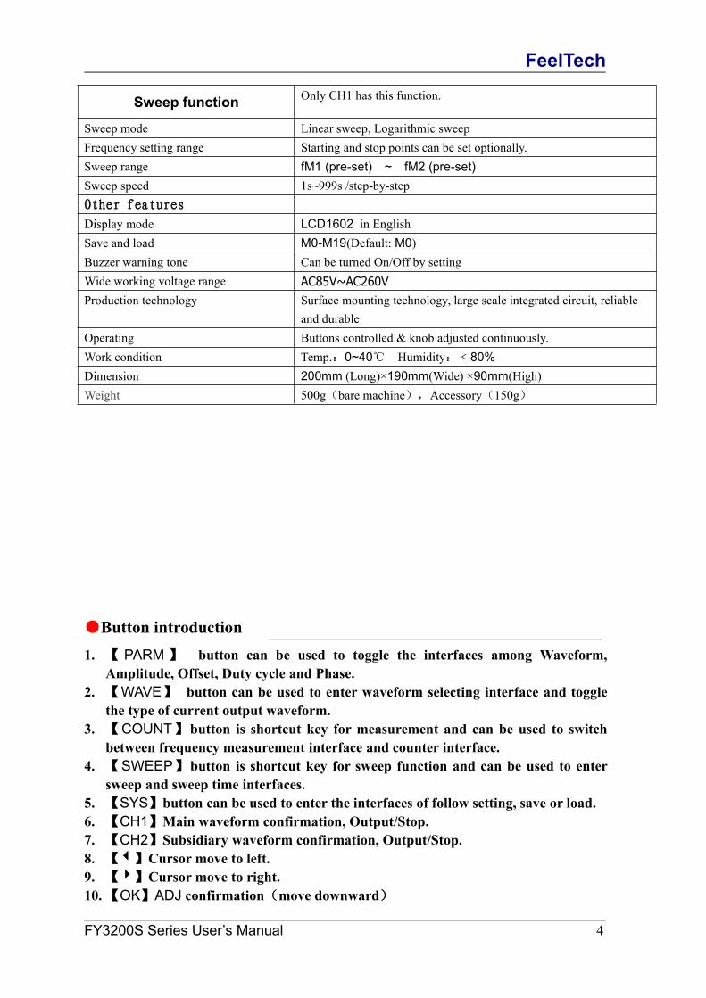
Sweep function Only CH1 has this function.
Sweep mode Linear sweep, Logarithmic sweepFrequency setting range Starting and stop points can be set optionally.Sweep range fM1 (pre-set) ~ fM2 (pre-set)Sweep speed 1s~999s /step-by-stepOther features
Display mode LCD1602 in EnglishSave and load M0-M19(Default: M0)Buzzer warning tone Can be turned On/Off by settingWide working voltage range AC85V~AC260VProduction technology Surface mounting technology, large scale integrated circuit, reliable
and durableOperating Buttons controlled & knob adjusted continuously.Work condition Temp.:0~40℃ Humidity:﹤80%Dimension 200mm (Long)×190mm(Wide) ×90mm(High)Weight 500g(bare machine),Accessory(150g)
●Button introduction1. 【 PARM 】 button can be used to toggle the interfaces among Waveform,
Amplitude, Offset, Duty cycle and Phase.2. 【WAVE】 button can be used to enter waveform selecting interface and toggle
the type of current output waveform.3. 【COUNT】button is shortcut key for measurement and can be used to switch
between frequency measurement interface and counter interface.4. 【SWEEP】button is shortcut key for sweep function and can be used to enter
sweep and sweep time interfaces.5. 【SYS】button can be used to enter the interfaces of follow setting, save or load.6. 【CH1】Main waveform confirmation, Output/Stop.7. 【CH2】Subsidiary waveform confirmation, Output/Stop.8. 【】Cursor move to left.9. 【】Cursor move to right.10.【OK】ADJ confirmation(move downward)

FeelTech
FY3200S Series User’s Manual 5
●Operating introduction1、Channel selection
After starting up, “MF” or “SF” will be displayed in the top left corner to indicate current channelselection state.
“MF” means choosing main channel for operation. “SF” means choosing subsidiary channelfor operation. It can be chosen by pressing【CH1】or 【CH2】accordingly.。
When the main channel has been chosen, press button【CH1】again and the main channeloutput will be shut down and the corresponding LED goes out.
Press the button【CH1】again and the main channel output will be activated again and thecorresponding LED illuminates
“SF” of 【CH2】operating the same way as above.。
2、Frequency adjustmentIf you want to adjust frequency of chosen main and subsidiary waveform, you need to make the
cursor point to frequency value. If the cursor is in other functions, you can use 【PARM】button tochange position.
(Note: The frequency value displayed for arbitrary waveform is referenced. The actual outputfrequency = Display value × periodicity of waveform defined by user).
Use 【ADJ】knob to change the frequency value of the cursor position. Rotate clockwise toincrease the frequency. Rotate anticlockwise to reduce the frequency.
If you want to change frequency value significantly, you can use 【】and 【】to movethe position of cursor.
【OK】button can change the unit of frequency displayed (Hz, kHz and MHz). Rotate the【ADJ】knob to change the number displayed to change the frequency.
Frequency unit is Hz
Frequency unit is MHzMF=0.02100000MHzAMPL=05.00V SINE
MF=0021000.00HzAMPL=05.00V SINE
MF=0021.00000kHzAMPL=05.00V SINE
MF=0021.00000kHzAMPL=05.00V SINE
MF=0010.00000kHzAMPL=05.00V SINE
SF=0010.00000kHzAMPL=05.00V SINE

FeelTech
FY3200S Series User’s Manual 6
3、Waveform selectionIn the interface of chosen main and subsidiary waveform, press 【WAVE】button can toggle among Sine
wave, Square wave, Triangle wave, Arbitrary wave and so on. You can also toggle the waveform quickly byrotating the【ADJ】knob. Press 【PARM】 button to quit waveform selection interface.
Main output of waveform is Sine wave.
Main output of waveform is Square wave.
Main output of waveform is Pulse wave.
Main output of waveform is Triangle wave.
Main output of waveform is Rise Sawtooth wave.
Main output of waveform is Fall Sawtooth wave.
Main output of waveform is DC wave.
Main output of waveform is Lorentz Pulses.
Main output of waveform is Multitone.
Main output of waveform is Random Noise.
MF=0021.00000kHzAMPL=05.00V SINE
MF=0021.00000kHzAMPL=05.00V SQUR
MF=0021.00000kHzAMPL=05.00V TRGL
MF=0021.00000kHzAMPL=05.00V PULS
MF=0021.00000kHzAMPL=05.00V STW
MF=0021.00000kHzAMPL=05.00V NSTW
MF=0021.00000kHzAMPL=05.00V DC
MF=0021.00000kHzAMPL=05.00V PRE1
MF=0021.00000kHzAMPL=05.00V PRE2
MF=0021.00000kHzAMPL=05.00V PRE3
FeelTech
FY3200S Series User’s Manual 7
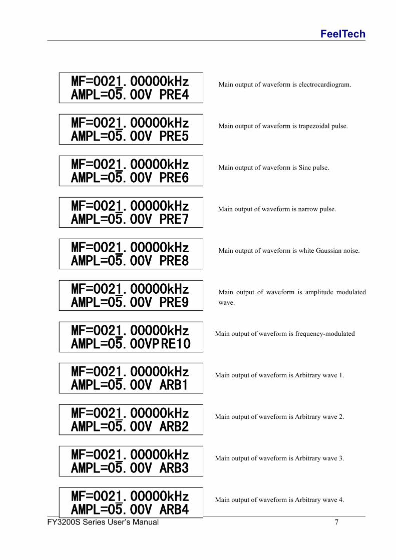
Main output of waveform is electrocardiogram.
Main output of waveform is trapezoidal pulse.
Main output of waveform is Sinc pulse.
Main output of waveform is narrow pulse.
Main output of waveform is white Gaussian noise.
Main output of waveform is amplitude modulatedwave.
Main output of waveform is frequency-modulated
Main output of waveform is Arbitrary wave 1.
Main output of waveform is Arbitrary wave 2.
Main output of waveform is Arbitrary wave 3.
Main output of waveform is Arbitrary wave 4.
MF=0021.00000kHzAMPL=05.00V ARB1
MF=0021.00000kHzAMPL=05.00V ARB2
MF=0021.00000kHzAMPL=05.00V ARB3
MF=0021.00000kHzAMPL=05.00V ARB4
MF=0021.00000kHzAMPL=05.00V PRE5
MF=0021.00000kHzAMPL=05.00V PRE6
MF=0021.00000kHzAMPL=05.00V PRE7
MF=0021.00000kHzAMPL=05.00V PRE8
MF=0021.00000kHzAMPL=05.00V PRE9
MF=0021.00000kHzAMPL=05.00VPRE10
MF=0021.00000kHzAMPL=05.00V PRE4
FeelTech
FY3200S Series User’s Manual 8
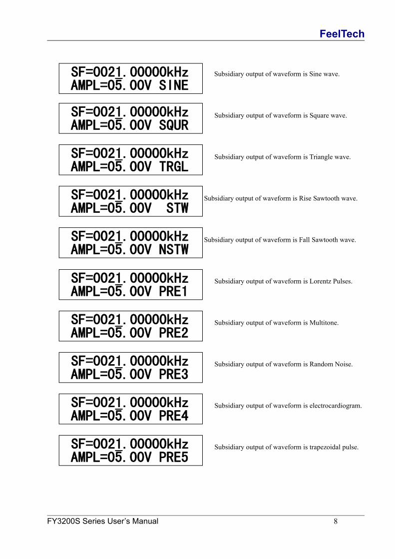
Subsidiary output of waveform is Sine wave.
Subsidiary output of waveform is Square wave.
Subsidiary output of waveform is Triangle wave.
Subsidiary output of waveform is Rise Sawtooth wave.
Subsidiary output of waveform is Fall Sawtooth wave.
Subsidiary output of waveform is Lorentz Pulses.
Subsidiary output of waveform is Multitone.
Subsidiary output of waveform is Random Noise.
Subsidiary output of waveform is electrocardiogram.
Subsidiary output of waveform is trapezoidal pulse.
SF=0021.00000kHzAMPL=05.00V SINE
SF=0021.00000kHzAMPL=05.00V SQUR
SF=0021.00000kHzAMPL=05.00V TRGL
SF=0021.00000kHzAMPL=05.00V STW
SF=0021.00000kHzAMPL=05.00V NSTW
SF=0021.00000kHzAMPL=05.00V PRE4
SF=0021.00000kHzAMPL=05.00V PRE5
SF=0021.00000kHzAMPL=05.00V PRE1
SF=0021.00000kHzAMPL=05.00V PRE2
SF=0021.00000kHzAMPL=05.00V PRE3

FeelTech
FY3200S Series User’s Manual 9
Subsidiary output of waveform is Sinc pulse.
Subsidiary output of waveform is narrow pulse.
Subsidiary output of waveform is white Gaussiannoise.
Subsidiary output of waveform is amplitudemodulated wave.
Subsidiary output of waveform isfrequency-modulated wave.
Subsidiary output of waveform is Arbitrary wave 1.
Subsidiary output of waveform is Arbitrary wave 2.
Subsidiary output of waveform is Arbitrary wave 3.
Subsidiary output of waveform is Arbitrary wave 4.
4、Amplitude adjustmentIn chosen main and subsidiary waveform interface, press 【PARM】button to make the cursor point to the
value of amplitude (AMPL=). The value (Vpp) is peak value of the signal. Use【】and【】buttons and【ADJ】knob to change the value. As follows:
SF=0021.00000kHzAMPL=05.00V ARB1
SF=0021.00000kHzAMPL=05.00V ARB2
SF=0021.00000kHzAMPL=05.00V ARB3
SF=0021.00000kHzAMPL=05.00V ARB4
MF=0021.00000kHzAMPL=05.00V TRGL
SF=0021.00000kHzAMPL=05.00V PRE6
SF=0021.00000kHzAMPL=05.00V PRE7
SF=0021.00000kHzAMPL=05.00V PRE8
SF=0021.00000kHzAMPL=05.00V PRE9
SF=0021.00000kHzAMPL=05.00VPRE10

FeelTech
FY3200S Series User’s Manual 10
5、Offset adjustmentIn chosen main and subsidiary waveform interface, press 【PARM】button to make the cursor point to the
value of offset (Offset=). Use【】and【】buttons and 【ADJ】knob to change the value. As follows:
6、Duty cycle adjustmentIn chosen main and subsidiary waveform interface, press 【PARM】button to make the cursor point to the
value of duty cycle (DUTY=). Use【】and【】buttons and 【ADJ】knob to change the value. (Duty cycleadjustment is invalid for Sine wave).As follows:
Duty cycle for Square wave can be adjusted from 0.1% to 99.9%.
(WAVE=SQUR)
(WAVE=SQUR)
Triangle wave adjustable among 50% (standard TRGL), above 50% and below 50% (both are differentsawtooth waves).
(WAVE=TRGL)
(WAVE=TRGL)
(WAVE=TRGL)
7、Phase adjustmentIn chosen Subsidiary waveform interface, press 【PARM】button to make the cursor point to the value of
phase(Phase=). Use【】and【】buttons and 【ADJ】knob to change the value of DC offset. The phasedifference of main wave and subsidiary wave can be adjusted from 0º to 359º. As follows:
MF=0021.00000kHzOffset=1.0V TRGL
MF=0021.00000kHzDUTY=50.0% SQUR
SQURMF=0021.00000kHzDUTY=80.0% SQUR
MF=0021.00000kHzDUTY=50.0% TRGL
TRGL
MF=0021.00000kHzDUTY=51.0% TRGL
TRGLMF=0021.00000kHzDUTY=49.0% TRGL
TRGL
SF=0021.00000kHzPhase=000º SQUR

FeelTech
FY3200S Series User’s Manual 11
8、Pulse width adjustment (pulse)Pulse positive pulse width can be set in the range of 10nS to 1S. The default value is 50nS.In CH1 channel waveform interface function is selected, press【WAVE】key to switch to the main waveform
pulse wave "PLUS" mode, press 【PARM】 key to make the cursor position corresponding positive pulseparameters (Pu =) , use【】and【】buttons and 【ADJ】knob to change the output positive pulse width canrange 10nS ~ 1S adjustment, As below:
9、Setting DC wave parameters (DC)DC wave can be set in the range of -10V to + 10V, the default value is 0V.In CH1 channel waveform interface function is selected, press【WAVE】key to switch to the main waveform
pulse wave "PLUS" mode, press 【PARM】 key to make the cursor position corresponding positive pulseparameters (Pu =) , use【】and【】buttons and 【ADJ】knob to change the output positive pulse width canrange 10nS ~ 1S adjustment, As below:
In CH1 or CH2 channel waveforms interface function is selected, press【WAVE】key to switch to the mainwave "DC" mode, press【PARM】 key to move the cursor to stay in offset level parameters corresponding tothe position ( Offs =), use【】and【】buttons and 【ADJ】knob to change the value of the output voltagedirect current wave can be adjusted in the range between -10V to + 10V, as shown below:
10、Measurement functionPress 【COUNT】button in any interface to enter measurement function. This instrument offers frequency
and counter two measurement functions. Input the signal from “Input” port on the front panel. Press 【COUNT】button again to switch between frequency measurement and counting pulse.
(Measure=FREQ)
Press 【ADJ】button to reset the counter. Rotate the 【ADJ】knob anticlockwise to pause (Doesn’t disturb counter). Rotate the 【ADJ】knob clockwise to cancel the pause.
(Measure=COUNT)
ExtF=21.000kHz*FUNC:EXT.TREQ
CNTR=0*FUNC:COUNGTER
SF=0021.00000kHzPu=0000000.010uSSQUR
SF=0021.00000kHzOffs=-5.00V DCSQUR

FeelTech
FY3200S Series User’s Manual 12
11、Trigger output functionIn counter function interface, press 【COUNT】button to enter waveform trigger output function. This
instrument offer manual trigger, external trigger and CH2 trigger for options. Rotate the 【ADJ】knob to adjustthe waveform amount for single trigger. Press【COUNT】button to toggle among manual trigger, external trigger ,CH2 trigger and measurement function.
(Manual trigger. Single trigger output 1 period
of waveform. Press 【ADJ】button to trigger.)
(External trigger. Single trigger output 12 periods
of waveform. Reverse the electric lever of input
port to trigger.)
(CH2 trigger. Single trigger output 13 periods
of waveform.Reverse the CH2 signal output to
trigger.)
12、FSK Frequency Shift KeyingFY3200S can FSK waveform from CH1 channel output. FY3200 provides two FSK trigger source: manual,
external. Trigger Mode Select 【COUNT】 button can be selected.The first frequency shift keying component is determined by the CH1 fundamental frequency, frequency
shift keying a second frequency component is determined by the FSK interface frequency F2, use【】 key and【】 key with parameter adjustment knob to change the“F2” output signal frequency value, As below:
F2 = 0020.00000KHz (manual trigger mode, one-shot output corresponding to the frequency of thewaveform F2
F2=0020.00000KHz (press the 【OK】 button Trigger)
FSK- Manual_Mod
F2=0020.00000KHz (external trigger mode, the trigger source INPUT terminal introduced)
FSK- Ext_Mod Terminal trigger source is INPUT , when a rising edge of the trigger signal “INPUT”, FSK output
signal at a frequency of CH1, when the falling edge of the trigger signal “INPUT”, FSK output frequencysignal corresponding to F2
CP_CNT=0000001Trigger Manual
CP_CNT=0000012Trigger Ext
CP_CNT=0000013Trigger CH2
FeelTech
FY3200S Series User’s Manual 13
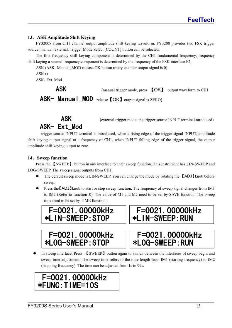
13、ASKAmplitude Shift KeyingFY3200S from CH1 channel output amplitude shift keying waveform. FY3200 provides two FSK trigger
source: manual, external. Trigger Mode Select [COUNT] button can be selected.The first frequency shift keying component is determined by the CH1 fundamental frequency, frequency
shift keying a second frequency component is determined by the frequency of the FSK interface F2,ASK (ASK- Manual_MOD release OK button rotary encoder output signal is 0)ASK ()ASK- Ext_Mod
ASK (manual trigger mode, press 【OK】 output waveform to CH1
ASK- Manual_MOD release【OK】output signal is ZERO)
ASK (external trigger mode, the trigger source INPUT terminal ntroduced)
ASK- Ext_Modtrigger source INPUT terminal is introduced, when a rising edge of the trigger signal INPUT, amplitude
shift keying output signal at a frequency of CH1, when INPUT falling edge of the trigger signal, the outputamplitude shift keying output to zero.
14、Sweep functionPress the【SWEEP】 button in any interface to enter sweep function. This instrument has LIN-SWEEP and
LOG-SWEEP. The sweep signal outputs from CH1. The default sweep mode is LIN-SWEEP. You can change the mode by rotating the【ADJ】knob before
sweep. Press the【ADJ】knob to start or stop sweep function. The frequency of sweep signal changes from fM1
to fM2 (Refer to function10). The value of M1 and M2 need to be set by SAVE function. The sweeptime need to be set by TIME function.
In sweep interface, Press 【SWEEP】button again to switch between the interfaces of sweep begin andsweep time adjustment. The sweep time refers to the time length from fM1 (starting frequency) to fM2(stopping frequency). The time can be adjusted from 1s to 99s.
F=0021.00000kHz*LIN-SWEEP:STOP
F=0021.00000kHz*LIN-SWEEP:RUN
F=0021.00000kHz*LOG-SWEEP:STOP
F=0021.00000kHz*LOG-SWEEP:RUN
F=0021.00000kHz*FUNC:TIME=10S

FeelTech
FY3200S Series User’s Manual 14
15、Save functionIn chosen main and subsidiary waveform interface, press【SYS】button to enter follow function and set if the
parameters of subsidiary waveform follow the parameters of main waveform. In this way, the correspondingparameters of CH2 will follow the change if the parameters of CH1 have been changed.
Frequency follow setting: Press【ADJ】button to change the frequency follow status.
The frequency of CH2 will not follow CH1
The frequency of CH2 will follow CH1
Amplitude follow setting: Rotate the 【ADJ】knob in follow mode setting interface to enter amplitudefollow interface. Press【ADJ】button to change the amplitude follow status.
The amplitude of CH2 will not follow CH1.
The amplitude of CH2 will follow CH1.
Offset follow setting: Rotate the 【ADJ】 knob in follow mode setting interface to enter offset followinterface. Press【ADJ】button to change the offset follow status.
The offset of CH2 will not follow CH1.
The offset of CH2 will follow CH1.
Duty cycle follow setting: Rotate the 【ADJ】 knob in follow mode setting interface to enter duty cyclefollow interface. Press【ADJ】button to change the duty cycle follow status.
The duty cycle of CH2 will not follow CH1.
The duty cycle of CH2 will follow CH1.
Freq CH1=CH2? NOFollowing
Freq CH1=CH2? OKFollowing
AMPL CH1=CH2? NOFollowing
AMPL CH1=CH2? OKFollowing
Offs CH1=CH2? NOFollowing
Offs CH1=CH2? OKFollowing
DUTY CH1=CH2? NOFollowing
DUTY CH1=CH2? OKFollowing

FeelTech
FY3200S Series User’s Manual 15
Waveform follow setting: Rotate the【ADJ】 knob in follow mode setting interface to enter waveformfollow interface. Press【ADJ】button to change the waveform follow status.
The waveform of CH2 will not follow CH1.
The waveform of CH2 will follow CH1.
Follow setting information saving: Rotate the【ADJ】 knob in follow mode setting interface to enterfollow setting information saving interface. Press 【ADJ】button to set follow status. ( Next startingmachine will affect follow status.
Follow setting information saving complete.
WAVE CH1=CH2? NOFollowing
WAVE CH1=CH2? OKFollowing
Save configuratiFollowing
Save configuratiFollowing OK

FeelTech
FY3200S Series User’s Manual 16
16、Save functionPress【SYS】button in follow function interface to enter save function. Current frequency value, amplitude
value, offset value, duty cycle, waveform and phase of main and subsidiary waveform can be saved. Thisinstrument provides 20 memory positions(M0~M19)for saving and can be loaded easily next time.
Rotate the【ADJ】 knob to choose saving position(M0~M19). Then press the【ADJ】button and “M”will display in the top right corner for a short while which means all the current parameters have beensaved to this position.
Position 0 (M0) is used to save the boot default parameters. The instrument will load all the parametersfrom this position next boot. As follows:
Position 1 (M1) is used to save starting frequency for sweep function which will be loaded by sweepfunction automatically. As follows:
Position 2 (M2) is used to save stop frequency for sweep function which will be loaded by sweepfunction automatically. As follows:
Positions 03~19 (M3~M19) are for user defined waveform. As follows:
17、Load functionPress 【PARM】button in save function interface to enter load function. It will enable the user to load the
frequency value, amplitude value, offset value, duty cycle, waveform and phase of main and subsidiary waveformfrom memory (M0~M19).
Rotate the【ADJ】knob to select the position(M0~M19)for loading. Press 【ADJ】button to confirm.“OK” will display in the top right for a short while which means loading complete.
If“Non”displays,it means no information in this position. Loading can’t be done.
MF=0021.00000kHz*SAVE P_ON FREQ
MF=0021.00000kHz*SAVE BEGIN FREQ
MF=0021.00000kHz*SAVE END FREQ
MF=0021.00000kHz*SAVE ADDR=03
MF=0021.00000kHz*FUNC:LOAD=00 OK
MF=0021.00000kHz*FUNC:LOAD=00 Non

FeelTech
FY3200S Series User’s Manual 17
●Other functions1、Duel TTL output are CH1 and CH2 waveform synchronized TTL waveform.2、Buzzer function. Each time when you press a button or rotate a knob, an impulse will be generated and thebuzzer will beep once. It will beep longer if invalid operation is conducted. The buzzer can be turned off bypressing and holding 【ADJ】button and then turning on the power switch in shutdown state if you don’t like thesound. The buzzer can be turned on by repeating above operations.
FeelTech
FY3200S Series User’s Manual 18
Appendix
Appendix A:Safety Notes1. Before using this instrument, please check if the power supply is normal, to ensure the
normal use and personal safety.2. This instrument must be used in the technical index range.3. Please do not change the instrument circuit arbitrarily, so as to avoid damaging
equipment or endangering the safety.
Appendix B:Warning and personal injuryDo not apply the product in the safety protection device or emergency stop device, or
any other applications that the product failure could result in personal injury, unless there isspecial purpose or use authorization. Before the installation and use, each parameter of thetechnical indexes in this manual should be referred to. If this suggestion is not obeyed,death or serious personal injury could be caused. In this condition the company will not beresponsible for any compensation of personal injury or death, and all the companymanagers and employees and auxiliary agents, distributors, other personnel concerned willbe released from any claim (including all the costs, expenses, attorney fees etc.) that mayresult in.
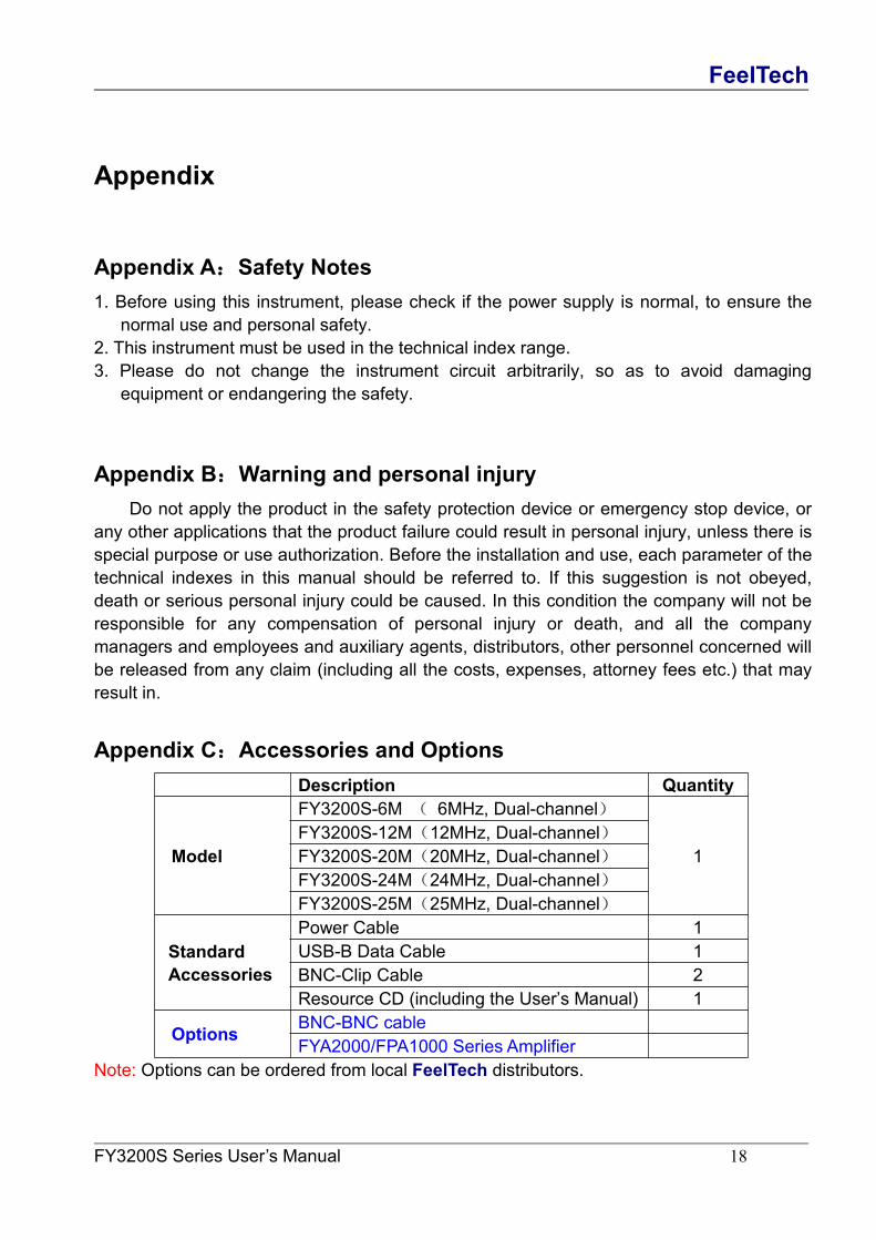
Appendix C:Accessories and OptionsDescription Quantity
Model
FY3200S-6M ( 6MHz, Dual-channel)
1FY3200S-12M(12MHz, Dual-channel)FY3200S-20M(20MHz, Dual-channel)FY3200S-24M(24MHz, Dual-channel)FY3200S-25M(25MHz, Dual-channel)
StandardAccessories
Power Cable 1USB-B Data Cable 1BNC-Clip Cable 2Resource CD (including the User’s Manual) 1
Options BNC-BNC cableFYA2000/FPA1000 Series Amplifier
Note: Options can be ordered from local FeelTech distributors.
FeelTech
FY3200S Series User’s Manual 19
Appendix D:WarrantyFeelTech warrants that its products mainframe and accessories will be free from
defects in materials and workmanship within the warranty period. If a product is proven to bedefective within the respective period, FeelTech guarantees the free replacement or repairof products which are approved defective. This product enjoy 1 year warranty since itsdelivery. Damages caused by misuse, vandalism, improper maintenance or force majeureare not covered by the warranty. Any disassembly or amendment without permission will bedeemed giving up warranty rights consciously.