fy series digital pid controller operation...
TRANSCRIPT
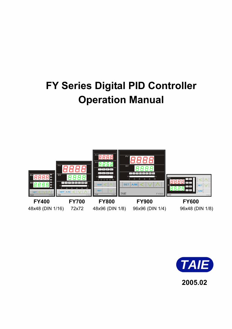
FY Series Digital PID Controller
Operation Manual
Y1
Y1
AT
AL
AL
PRO
1
2
FY400 FY700 FY800 FY900 FY600
48x48 (DIN 1/16) 72x72 48x96 (DIN 1/8) 96x96 (DIN 1/4) 96x48 (DIN 1/8)
TAIE 2005.02
1
CONTENT 1 Notice before start- up ……………………………………………………… Page 3 2 Specifications ………………………………………………………………… Page 4 3 Terminal arrangement
3.1 FY400 Terminals ……………………………………………………… Page 6 3.2 FY600 Terminals ……………………………………………………… Page 7 3.3 FY700 Terminals ……………………………………………………… Page 8 3.4 FY800 Terminals ……………………………………………………… Page 9 3.5 FY900 Terminals ……………………………………………………… Page 10
4 External dimension and panel cutout …………………………………… Page 11 5 Parts description…………… ……………………………………………… Page 12 6 Operations
6.1 Power On …………………………………………………………….. Page 13 6.2 Change the Set Value (SV) ………………………………………… Page 13 6.3 Change The Alarm Value…………………………………………… Page 13 6.4 Autotuning (AT) ……………..………………………………………… Page 14 6.5 Programmable RAMP / SOAK ……………………………………….. Page 15
7 Operation levels 7.1 Levels diagram ………………………………………………………. Page 16 7.2 Lock function ……………………………..……………………..…… Page 16
8 Parameters 8.1 Level 1 (User Level) ………………………………………………… Page 17 8.2 Level 2 (PID Level)
8.2.1 Level 2 parameters display / hiding condition…..……... Page 18 8.2.2 Description of parameters………………………………… Page 19
8.3 Level 3 (Input Level) ………………………………………………… Page 20 8.4 Level 4 (SET Level)
8.4.1 How to hide parameters (Use SET1~SET7) …………… Page 22 8.4.2 Special functions (Use SET8 / SET9 / SET0)………..… Page 23 8.4.3 Remote SV type selection…………………………………… Page 24 8.4.4 Output mode selection (Use OUTY) ……………………… Page 24
8.5 Program Level 8.5.1 Description of parameters ………………………………… Page 25 8.5.2 Description of operation…………………………………… Page 26
9 Input type table ………………………………………………………………… Page 27 10 Alarm
10.1 Alarm time……………………………………………………………… Page 29 10.2 SETA …………………………………………………………………… Page 29 10.3 Alarm mode …………………………………………………………… Page 30
2
11 Error codes ………………………………………………………………… Page 31 12 Modify input type: TC, RTD ……………………………………………… Page 32 13 Modify input type: Linear Input (mA ,V)
13.1 Hardware ……………………………………………………………… Page 33 13.2 Calibration ……………………………………………………………… Page 34
14 Modify output type: Relay, SSR, 4~20mA ………………………………… Page 35 15 Modify output mode: OUT1/ALARM, OUT1/OUT2 ……………………… Page 35 16 Applications
16.1 RAMP & SOAK ………………………..……………………………… Page 36 16.2 TTL Communication:SV output and RATE function……………… Page 37 16.3 1ψ Phase angle control (By SCR module) ………………………… Page 38 16.4 1ψPhase angle control (By TRIAC) …………...…………………… Page 39 16.5 3ψPhase angle control ( By DIODE/SCR module)……………….. Page 40 16.6 1ψZero crossing control (By SCR Module) ………………..……… Page 41 16.7 1ψZero crossing control (By TRIAC) ……………….……………… Page 42 16.8 3ψZero crossing control (By SCR module) ……………………… Page 43 16.9 3ψZero crossing control (By TRIAC) ……………………………… Page 44 16.10 3 wires proportional motor valve control ……………..………… Page 45 16.11 Communication
16.11.1 Protocol …………………………………………………… Page 46 16.11.2 Wiring diagram ……………………………………………… Page 49
3
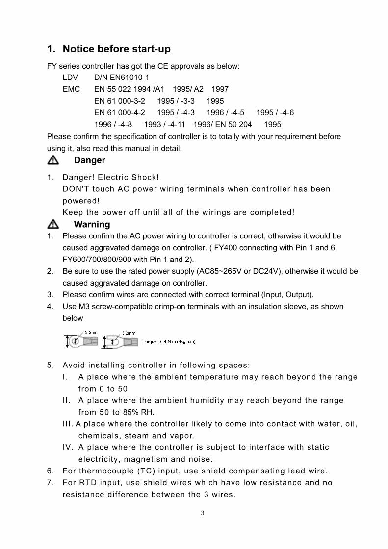
1. Notice before start-up FY series controller has got the CE approvals as below:
LDV: D/N EN61010-1 EMC: EN 55 022 1994 /A1:1995/ A2:1997
EN 61 000-3-2: 1995 / -3-3: 1995 EN 61 000-4-2: 1995 / -4-3: 1996 / -4-5: 1995 / -4-6 1996 / -4-8: 1993 / -4-11:1996/ EN 50 204: 1995
Please confirm the specification of controller is to totally with your requirement before using it, also read this manual in detail.
Danger
1. Danger! Electric Shock! DON'T touch AC power wiring terminals when controller has been powered!
Keep the power off until all of the wirings are completed!
Warning 1. Please confirm the AC power wiring to controller is correct, otherwise it would be
caused aggravated damage on controller. ( FY400 connecting with Pin 1 and 6, FY600/700/800/900 with Pin 1 and 2).
2. Be sure to use the rated power supply (AC85~265V or DC24V), otherwise it would be caused aggravated damage on controller.
3. Please confirm wires are connected with correct terminal (Input, Output). 4. Use M3 screw-compatible crimp-on terminals with an insulation sleeve, as shown
below
5. Avoid install ing controller in following spaces: I. A place where the ambient temperature may reach beyond the range
from 0 to 50 II. A place where the ambient humidity may reach beyond the range
from 50 to 85% RH. III. A place where the control ler l ikely to come into contact with water, oi l,
chemicals, steam and vapor. IV. A place where the controller is subject to interface with static
electricity, magnetism and noise. 6. For thermocouple (TC) input, use shield compensating lead wire. 7. For RTD input, use shield wires which have low resistance and no
resistance dif ference between the 3 wires.
4
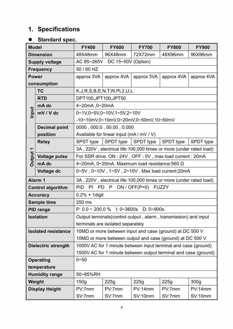
1. Specifications Standard spec.
Model FY400 FY600 FY700 FY800 FY900 Dimension 48X48mm 96X48mm 72X72mm 48X96mm 96X96mm Supply voltage AC 85~265V,DC 15~50V (Option) Frequency 50 / 60 HZ Power consumption
approx 3VA approx 4VA approx 3VA approx 4VA approx 4VA
TC K,J,R,S,B,E,N,T,W,PL2,U,L RTD DPT100,JPT100,JPT50 mA dc 4~20mA ,0~20mA mV / V dc 0~1V,0~5V,0~10V,1~5V,2~10V
-10~10mV,0~10mV,0~20mV,0~50mV,10~50mV
Inpu
t
Decimal point position
0000 , 000.0 , 00.00 , 0.000 Available for linear input (mA / mV / V) SPST type SPDT type SPDT type SPDT type SPDT type Relay 3A , 220V , electrical life:100,000 times or more (under rated load)
Voltage pulse For SSR drive. ON : 24V , OFF : 0V , max load current : 20mA mA dc 4~20mA, 0~20mA. Maximum load resistance:560 Ω O
utpu
t 1
Voltage dc 0~5V , 0~10V , 1~5V , 2~10V . Max load current:20mA
Alarm 1 3A , 220V , electrical life:100,000 times or more (under rated load) Control algorithm PID,PI,PD,P,ON / OFF(P=0),FUZZY。 Accuracy 0.2% + 1digit Sample time 250 ms PID range P: 0.0 ~ 200.0 %,I: 0~3600s,D: 0~900s Isolation Output terminals(control output , alarm , transmission) and input
terminals are isolated separately Isolated resistance 10MΩ or more between input and case (ground) at DC 500 V
10MΩ or more between output and case (ground) at DC 500 V Dielectric strength 1000V AC for 1 minute between input terminal and case (ground)
1500V AC for 1 minute between output terminal and case (ground)Operating temperature
0~50
Humidity range 50~85%RH Weight 150g 225g 225g 225g 300g Display Height PV:7mm
SV:7mm PV:7mm SV:7mm
PV:14mm SV:10mm
PV:7mm SV:7mm
PV:14mm SV:10mm
5
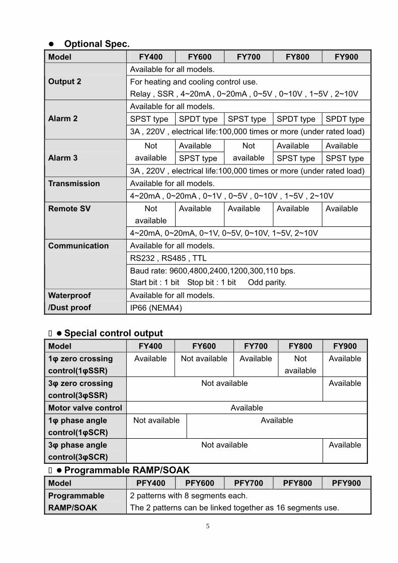
Optional Spec. Model FY400 FY600 FY700 FY800 FY900
Available for all models. Output 2 For heating and cooling control use.
Relay , SSR , 4~20mA , 0~20mA , 0~5V , 0~10V , 1~5V , 2~10V Available for all models. SPST type SPDT type SPST type SPDT type SPDT type
Alarm 2
3A , 220V , electrical life:100,000 times or more (under rated load)
Available Available Available Not available SPST type
Not available SPST type SPST type
Alarm 3
3A , 220V , electrical life:100,000 times or more (under rated load) Available for all models. Transmission 4~20mA , 0~20mA , 0~1V , 0~5V , 0~10V , 1~5V , 2~10V
Not available
Available Available Available Available Remote SV
4~20mA, 0~20mA, 0~1V, 0~5V, 0~10V, 1~5V, 2~10V Available for all models. RS232 , RS485 , TTL
Communication
Baud rate: 9600,4800,2400,1200,300,110 bps. Start bit : 1 bit,Stop bit : 1 bit ,Odd parity. Available for all models. Waterproof
/Dust proof IP66 (NEMA4)
Special control output Model FY400 FY600 FY700 FY800 FY900 1φ zero crossing control(1φSSR)
Available Not available Available Not available
Available
3φ zero crossing control(3φSSR)
Not available Available
Motor valve control Available 1φ phase angle control(1φSCR)
Not available Available
3φ phase angle control(3φSCR)
Not available Available
Programmable RAMP/SOAK Model PFY400 PFY600 PFY700 PFY800 PFY900 Programmable RAMP/SOAK
2 patterns with 8 segments each. The 2 patterns can be linked together as 16 segments use.
6
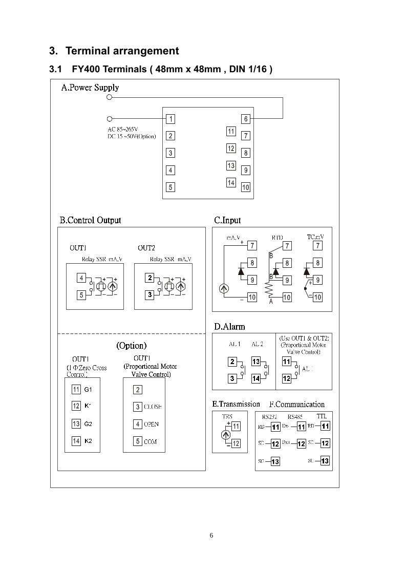
3. Terminal arrangement 3.1 FY400 Terminals ( 48mm x 48mm , DIN 1/16 )
7
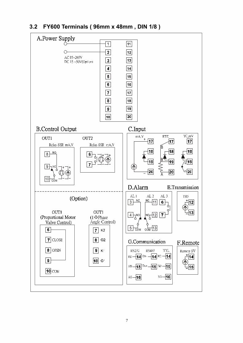
3.2 FY600 Terminals ( 96mm x 48mm , DIN 1/8 )
8
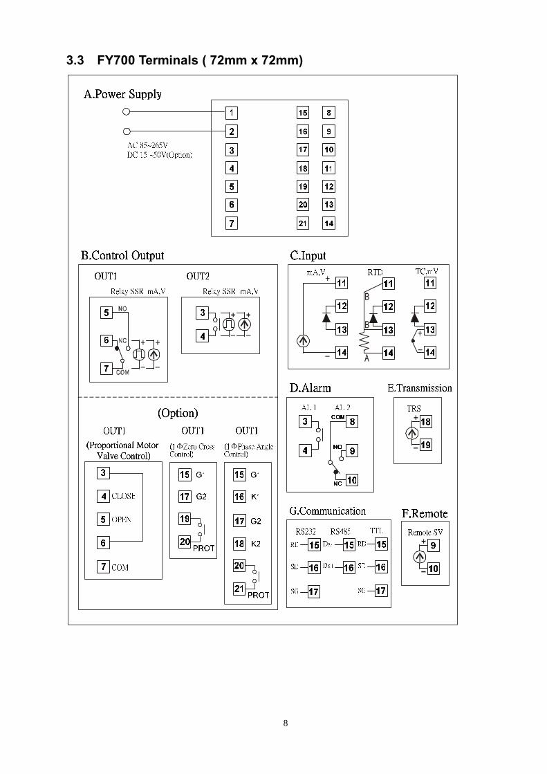
3.3 FY700 Terminals ( 72mm x 72mm)
9
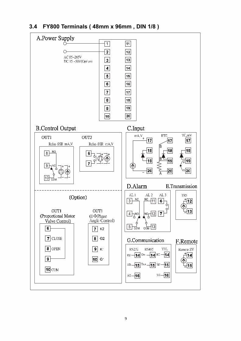
3.4 FY800 Terminals ( 48mm x 96mm , DIN 1/8 )
10
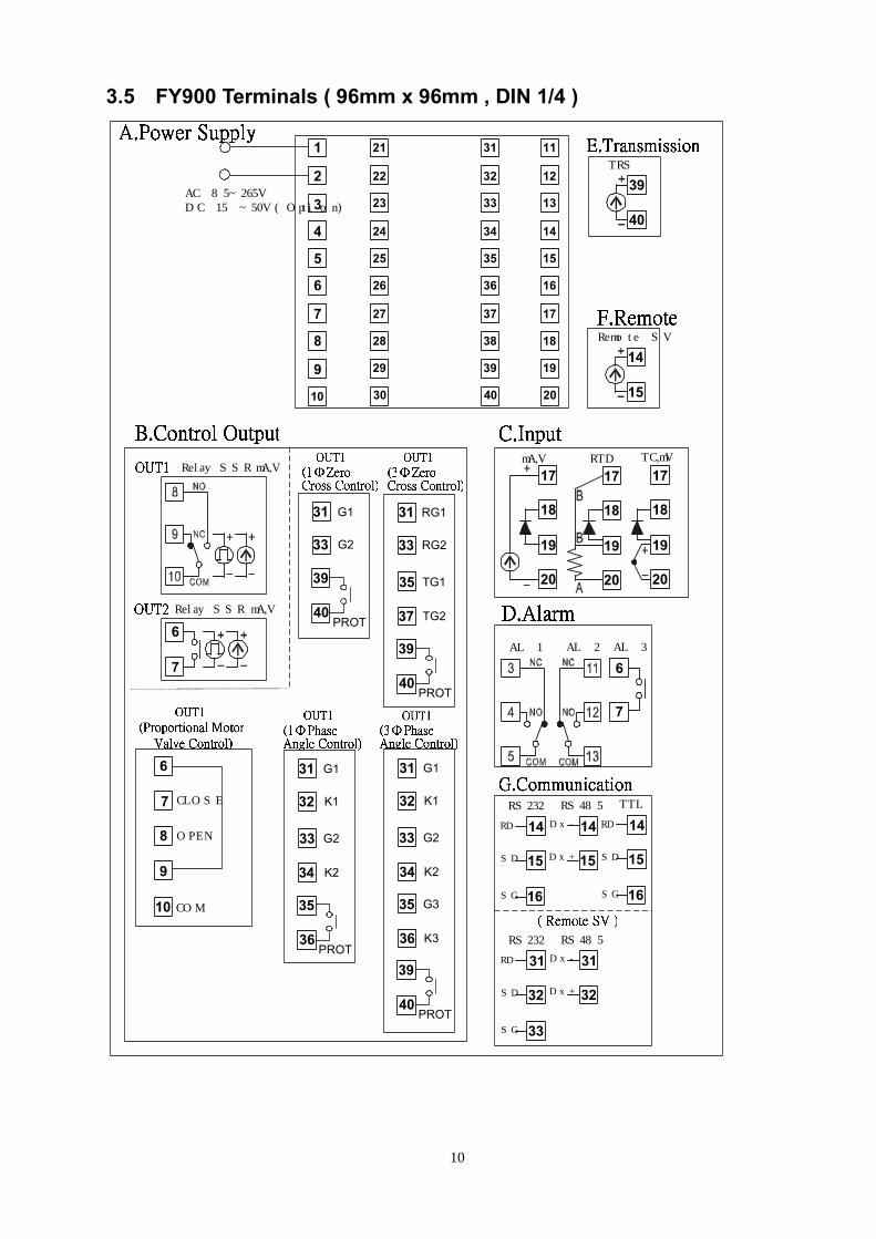
3.5 FY900 Terminals ( 96mm x 96mm , DIN 1/4 )
AC 85~265VDC 15 ~50V(Option)
RelaySSR mA,V
RelaySSR mA,V
6
7
mA,V RTDTC,mV
AL 1
6
7
AL 2
TRS
RS232
14
15
16
RD
SD
SG
RS485
14
15
Dx-
Dx+
TTL
14
15
16
RD
SD
SG
1
2
3
4
5
6
7
8
9
10
21
22
23
24
25
26
27
28
29
30
17
18
19
20
17
18
19
20
17
18
19
20
AL 3
39
40
Remote SV
14
15
G1
G2
40
31
33
39
PROT
G1
K1
G2
K2
CLOSE
OPEN
COM
6
7
8
9
10
36
31
32
33
34
35
PROT
RG1
RG2
TG1
TG2
40
31
33
35
37
39
PROT
G1
K1
G2
K2
40
31
32
33
34
39
PROT
G3
K3
35
36 RS232
31
32
33
RD
SD
SG
RS485
31
32
Dx-
Dx+
11
12
13
14
15
16
17
18
19
20
31
32
33
34
35
36
37
38
39
40
11
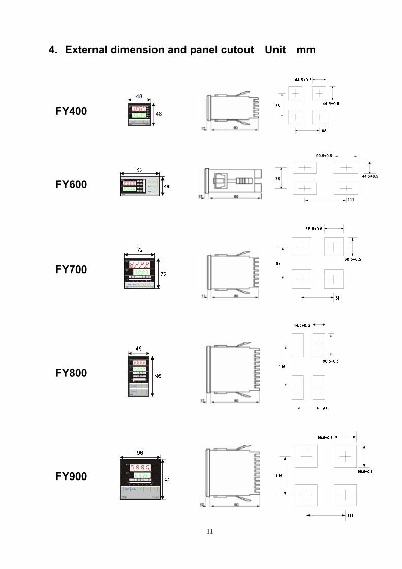
4. External dimension and panel cutout〈Unit:mm〉
FY400 Y1
Y2
AT
AL
AL
PRO
1
2 48
48
FY600
90.5+0.5
44.5+0.5
111
70
FY700
FY800
FY900
12
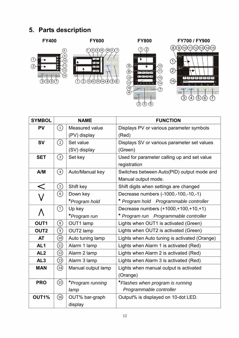
5. Parts description FY400
Y1
Y2
AT
AL
AL
PRO
1
2
1
2
3 5 6 7
10
11
12
15
9
8
FY600 FY800 1 2
9
8
12
4
3 5 6
7
13
16
14
15
11
10
FY700 / FY900
1
2
16
3 4 5 6 7
8 9 10 11 12 13 14 15
SYMBOL NAME FUNCTION
PV 1 Measured value (PV) display
Displays PV or various parameter symbols (Red)
SV 2 Set value (SV) display
Displays SV or various parameter set values (Green)
SET 3 Set key Used for parameter calling up and set value registration
A/M 4 Auto/Manual key Switches between Auto(PID) output mode and Manual output mode.
5 Shift key Shift digits when settings are changed
6 Down key
*Program hold Decrease numbers (-1000,-100,-10,-1) * Program hold〈Programmable controller〉
7 Up key
*Program run Decrease numbers (+1000,+100,+10,+1) * Program run〈Programmable controller〉
OUT1 8 OUT1 lamp Lights when OUT1 is activated (Green) OUT2 9 OUT2 lamp Lights when OUT2 is activated (Green)。
AT 10 Auto tuning lamp Lights when Auto tuning is activated (Orange) AL1 11 Alarm 1 lamp Lights when Alarm 1 is activated (Red) AL2 12 Alarm 2 lamp Lights when Alarm 2 is activated (Red) AL3 13 Alarm 3 lamp Lights when Alarm 3 is activated (Red) MAN 14 Manual output lamp Lights when manual output is activated
(Orange) PRO 15 *Program running
lamp *Flashes when program is running 〈Programmable controller〉。
OUT1% 16 OUT% bar-graph display
Output% is displayed on 10-dot LED.

13
6. Operations 6.1 Power On Controller will display as following::
6.2 Change the Set Value (SV) Change SV from 0.0 to 100.0
6.3 Change the Alarm Value Change AL1 value to “5.0” (AL1 active, if PV exceeds SV over 5.0)
* The are total 16 alarm mode types, please referred with “alarm mode” in page 30
* To change alarm mode, press + key 5 seconds to enter Level 3 (Input
Level) and then change ALD1/ALD2/ALD3 value.

14
6.4 Autotuning (AT) Use AT function to automatically calculate and set the optimize PID value for your system.
Press keyto display parameter AT.
Press keyto change AT setting
Press keychange AT to “YES”
Press keyStart auto tuning(AT lamp will be lighted on)
SETSET
OFFON ON OFF
ON / OFF Control(Autotuning)
PID Control(After Autotuning)
SVPV
0%
100%Output%
AutotuningATVL=0
OFFON ON OFF
SV
PV
0%
100%
AutotuningATVL=20
SV - 20
Autotuning failure
(Overshoot )
*Set ATVL to prevent overshoot occurred duringautotuning process.
Output%
ON / OFF Control(Autotuning)
PID Control(After Autotuning)
To set ATVL ,press key 5 seconds to enterLevel 2 (PID Level) and then change the value.
SET
Possible cause 1: ATVL is too big. (If not sure,set ATVL=0)Possible cause 2:Calculation time is too long.
(Set PID parameter manually)
15
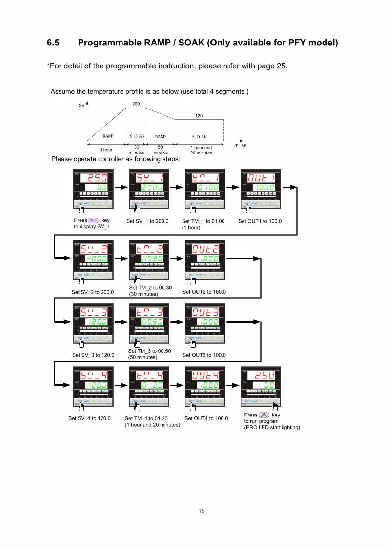
6.5 Programmable RAMP / SOAK (Only available for PFY model) *For detail of the programmable instruction, please refer with page 25.
Press keyto display SV_1
Set SV_1 to 200.0 Set TM_1 to 01.00(1 hour)
Set OUT1 to 100.0SET
Assume the temperature profile is as below (use total 4 segments )
TIME
SV
RAMP SOAKRAMP SOAK
1 hour 30minutes
50minutes
1 hour and20 minutes
200
120
Set SV_2 to 200.0Set TM_2 to 00.30(30 minutes) Set OUT2 to 100.0
Set SV_3 to 120.0Set TM_3 to 00.50(50 minutes) Set OUT3 to 100.0
Set SV_4 to 120.0 Set TM_4 to 01.20(1 hour and 20 minutes)
Set OUT4 to 100.0Press keyto run program(PRO LED start lighting)
Please operate conroller as following steps:

16
7. Operation levels 7.1 Levels diagram
7.2 Lock function To use lock function, please set parameter “LCK” in level 2.
Levels entering available LCK Level 1(User)
Level 2 (PID)
Level 3(Input)
Level 4(SET)
Parameters which can be changed
------ All parameters (Factory set value)
------ All parameters
------ ------ All parameters except level 3
------ ------ Parameters in level 1
------ ------ “SV” and “LCK”
------ ------ Only “LCK”
17
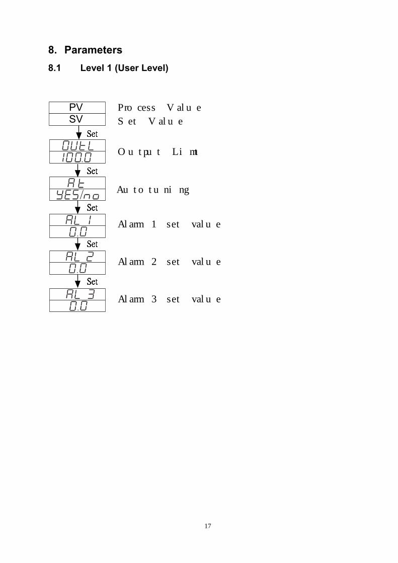
8. Parameters 8.1 Level 1 (User Level)
Process Value
Set Value
Output Limt
Autotuning
Alarm 1 set value
Alarm 2 set value
Alarm 3 set value
PVSV
18
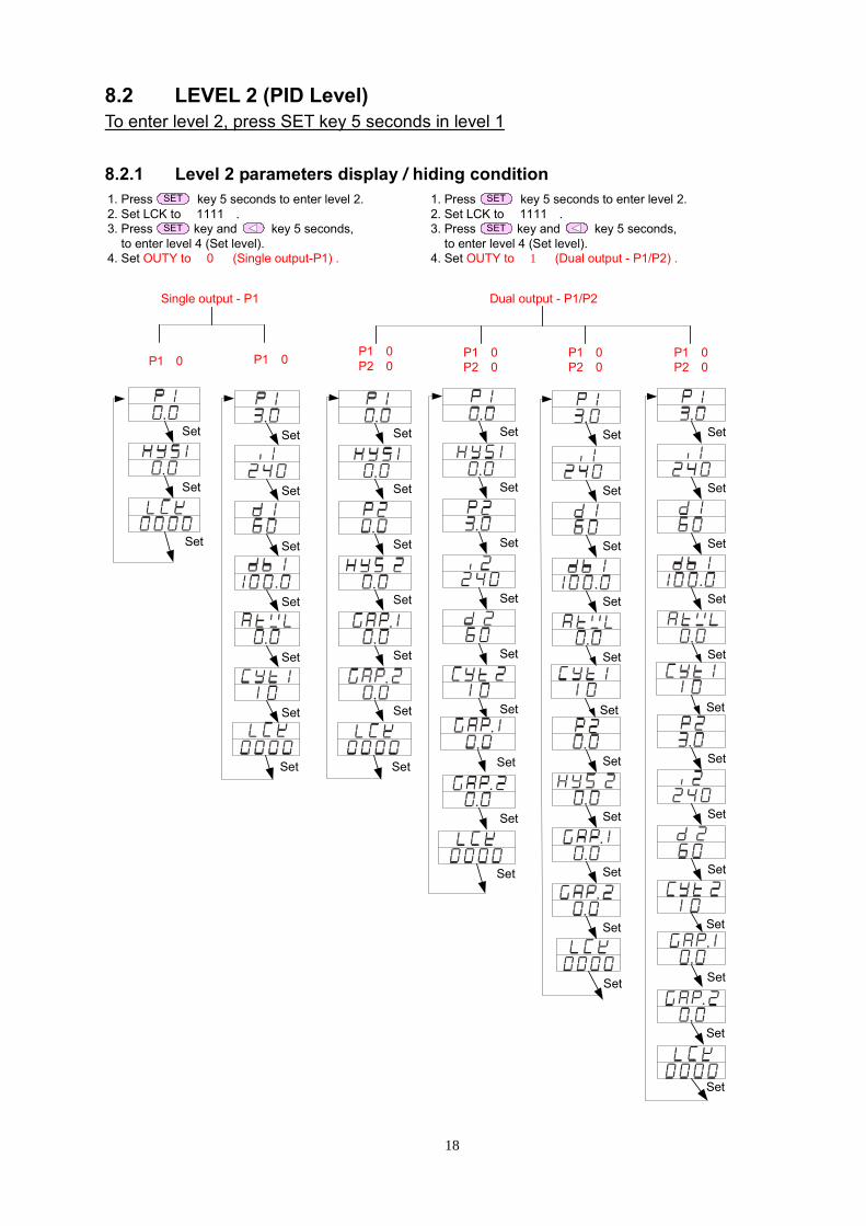
8.2 LEVEL 2 (PID Level) To enter level 2, press SET key 5 seconds in level 1 8.2.1 Level 2 parameters display / hiding condition
Set
Set
Set
Set
Set
Set
P1≠0
Set
P1=0
Set
Set
Set
Set
Set
Set
Set
Set
Set
P1=0P2=0
Set
Set
Set
Set
Set
Set
Set
P1=0P2≠0
Set
Set
Set
Set
Set
Set
Set
P1≠0P2=0
Set
Set
Set
Set
Set
Set
Set
Set
Set
Set
P1≠0P2≠0
Set
Set
Set
Set
Set
Set
Set
Set
Set
1. Press key 5 seconds to enter level 2.2. Set LCK to“1111”.3. Press key and key 5 seconds, to enter level 4 (Set level).4. Set OUTY to“0” (Single output-P1) .
SET
SET
Set
Single output - P1
1. Press key 5 seconds to enter level 2.2. Set LCK to“1111”.3. Press key and key 5 seconds, to enter level 4 (Set level).4. Set OUTY to“1”(Dual output - P1/P2) .
SET
SET
Dual output - P1/P2
19
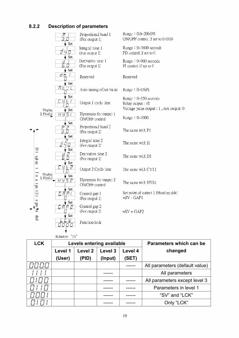
8.2.2 Description of parameters
Displayifoutput2isprovided
Levels entering available LCK
Level 1(User)
Level 2 (PID)
Level 3(Input)
Level 4(SET)
Parameters which can be changed
------ All parameters (default value)
------ All parameters
------ ------ All parameters except level 3
------ ------ Parameters in level 1
------ ------ “SV” and “LCK”
------ ------ Only “LCK”
20
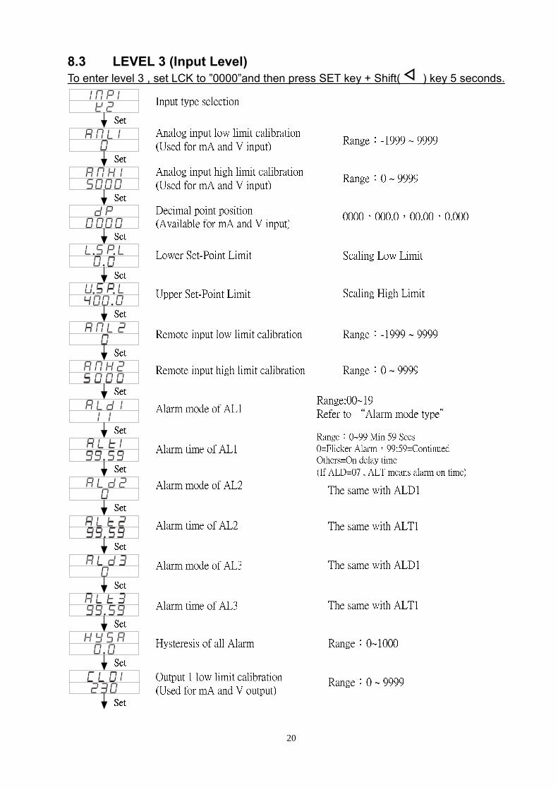
8.3 LEVEL 3 (Input Level) To enter level 3 , set LCK to ”0000”and then press SET key + Shift( ) key 5 seconds.
21

22
8.4 Level 4 (SET level) To enter level 4, set LCK to ”1111”and then press SET key + Shift( ) key 5 seconds.
8.4.1 How to hide parameters (Use SET1~SET7)
*For the description of Level 1 parameters, please refer with page 17. *For the description of Level 3 parameters, please refer with page 20.
SET Display / hiding Level SET Display / hiding Level 1_ 1 Level 1 5_ 1 , Level 3 1_ 2 Level 1 5_ 2 , Level 3 1_ 3 Level 1 5_ 3 , , Level 3 1_ 4 Level 1 5_ 4 , Level 3 2_ 1 Level 1 6_ 1 Level 3 2_ 2 , , Level 3 6_ 2 Level 3 2_ 3 , Level 3 6_ 3 Level 3 2_ 4 , Level 3 6_ 4 Level 3 3_ 1 Level 3 7_ 1 Level 3 3_ 2 Level 3 7_ 2 Level 3 3_ 3 Level 3 7_ 3 Level 3 3_ 4 Level 3 7_ 4 Level 3 4_ 1 Level 3 4_ 2 Level 3 4_ 3 Level 3 4_ 4 , Level 3
23
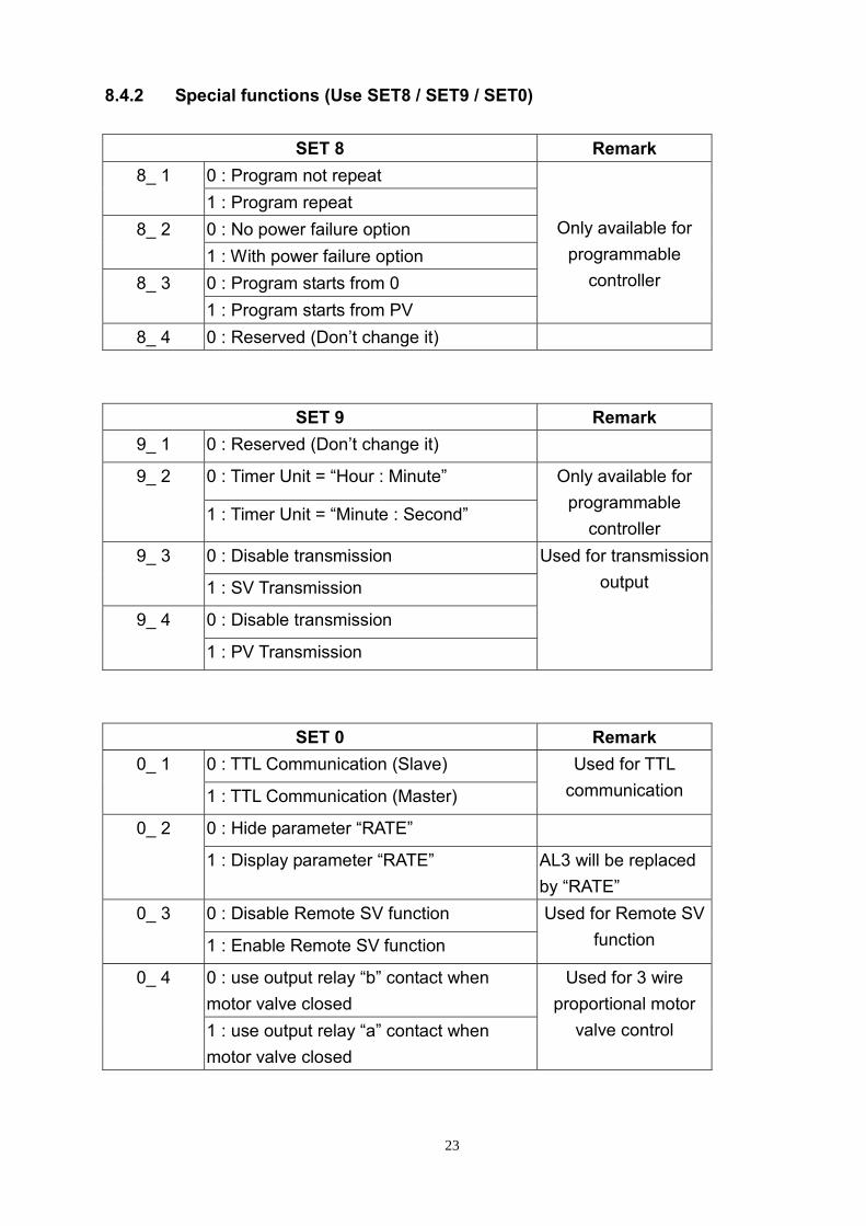
8.4.2 Special functions (Use SET8 / SET9 / SET0)
SET 8 Remark 0 : Program not repeat 8_ 1 1 : Program repeat 0 : No power failure option 8_ 2 1 : With power failure option 0 : Program starts from 0 8_ 3 1 : Program starts from PV
Only available for programmable
controller
8_ 4 0 : Reserved (Don’t change it)
SET 9 Remark 9_ 1 0 : Reserved (Don’t change it)
0 : Timer Unit = “Hour : Minute” 9_ 2
1 : Timer Unit = “Minute : Second”
Only available for programmable
controller 0 : Disable transmission 9_ 3
1 : SV Transmission
0 : Disable transmission 9_ 4
1 : PV Transmission
Used for transmission output
SET 0 Remark 0 : TTL Communication (Slave) 0_ 1
1 : TTL Communication (Master)
Used for TTL communication
0 : Hide parameter “RATE” 0_ 2
1 : Display parameter “RATE” AL3 will be replaced by “RATE”
0 : Disable Remote SV function 0_ 3
1 : Enable Remote SV function
Used for Remote SV function
0 : use output relay “b” contact when motor valve closed
0_ 4
1 : use output relay “a” contact when motor valve closed
Used for 3 wire proportional motor
valve control
24
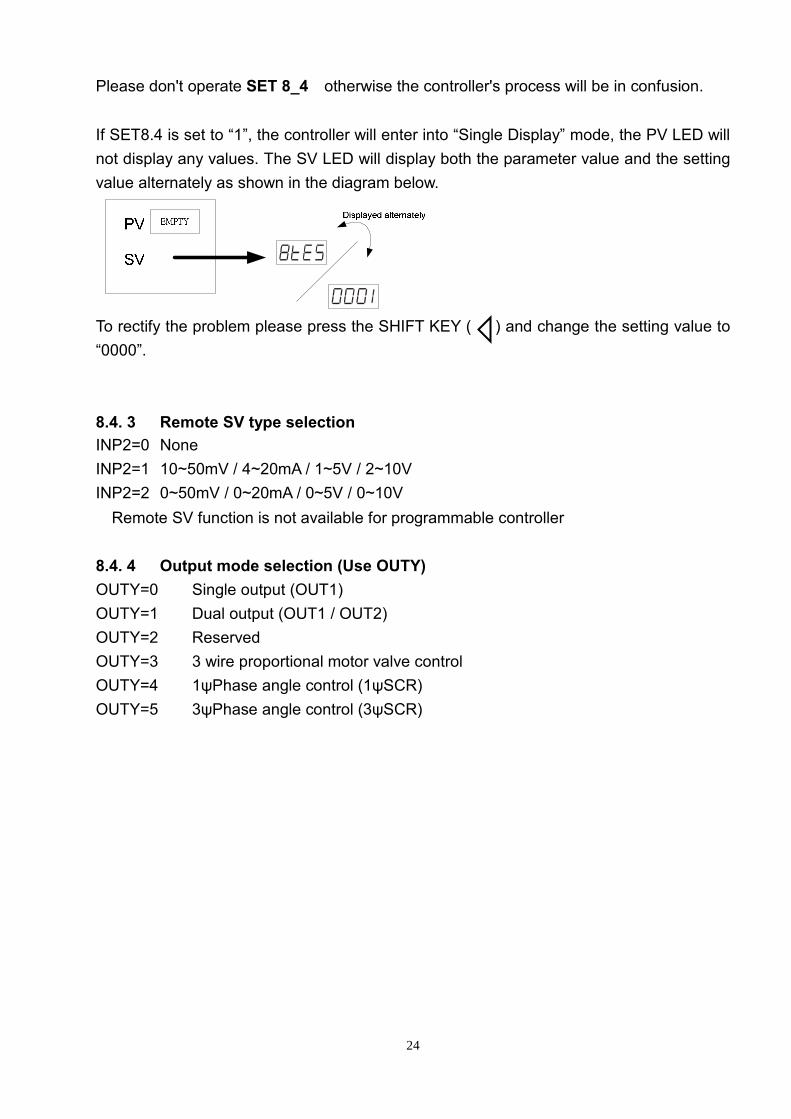
Please don't operate SET 8_4,otherwise the controller's process will be in confusion. If SET8.4 is set to “1”, the controller will enter into “Single Display” mode, the PV LED will not display any values. The SV LED will display both the parameter value and the setting value alternately as shown in the diagram below.
To rectify the problem please press the SHIFT KEY ( ) and change the setting value to “0000”. 8.4. 3 Remote SV type selection INP2=0 None。 INP2=1 10~50mV / 4~20mA / 1~5V / 2~10V。 INP2=2 0~50mV / 0~20mA / 0~5V / 0~10V。 ※Remote SV function is not available for programmable controller 8.4. 4 Output mode selection (Use OUTY) OUTY=0 Single output (OUT1) OUTY=1 Dual output (OUT1 / OUT2) OUTY=2 Reserved OUTY=3 3 wire proportional motor valve control OUTY=4 1ψPhase angle control (1ψSCR) OUTY=5 3ψPhase angle control (3ψSCR)
25
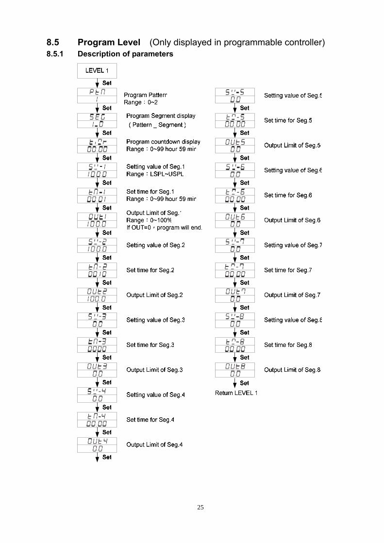
8.5 Program Level (Only displayed in programmable controller) 8.5.1 Description of parameters
26
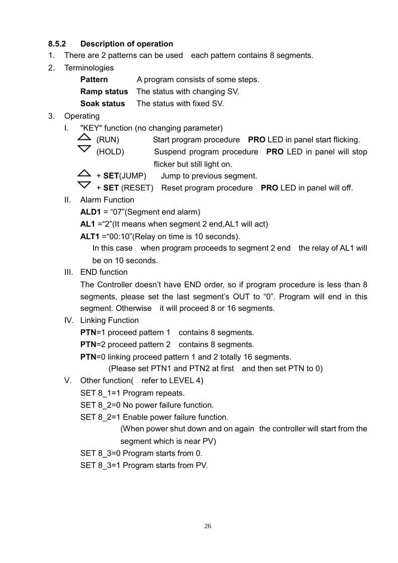
8.5.2 Description of operation 1. There are 2 patterns can be used,each pattern contains 8 segments. 2. Terminologies
Pattern :A program consists of some steps. Ramp status:The status with changing SV. Soak status :The status with fixed SV.
3. Operating I. "KEY" function (no changing parameter)
(RUN) :Start program procedure,PRO LED in panel start flicking. (HOLD) :Suspend program procedure,PRO LED in panel will stop
flicker but still light on. + SET(JUMP) :Jump to previous segment.
+ SET (RESET):Reset program procedure,PRO LED in panel will off. II. Alarm Function:
ALD1 = “07”(Segment end alarm), AL1 =“2”(It means when segment 2 end,AL1 will act), ALT1 =“00:10”(Relay on time is 10 seconds). * In this case,when program proceeds to segment 2 end,the relay of AL1 will
be on 10 seconds. III. END function:
The Controller doesn’t have END order, so if program procedure is less than 8 segments, please set the last segment’s OUT to “0”. Program will end in this segment. Otherwise,it will proceed 8 or 16 segments.
IV. Linking Function: PTN=1 proceed pattern 1,contains 8 segments. PTN=2 proceed pattern 2,contains 8 segments. PTN=0 linking proceed pattern 1 and 2 totally 16 segments.
(Please set PTN1 and PTN2 at first,and then set PTN to 0) V. Other function(*refer to LEVEL 4)
SET 8_1=1 Program repeats. SET 8_2=0 No power failure function. SET 8_2=1 Enable power failure function.
(When power shut down and on again,the controller will start from the segment which is near PV)
SET 8_3=0 Program starts from 0. SET 8_3=1 Program starts from PV.
27
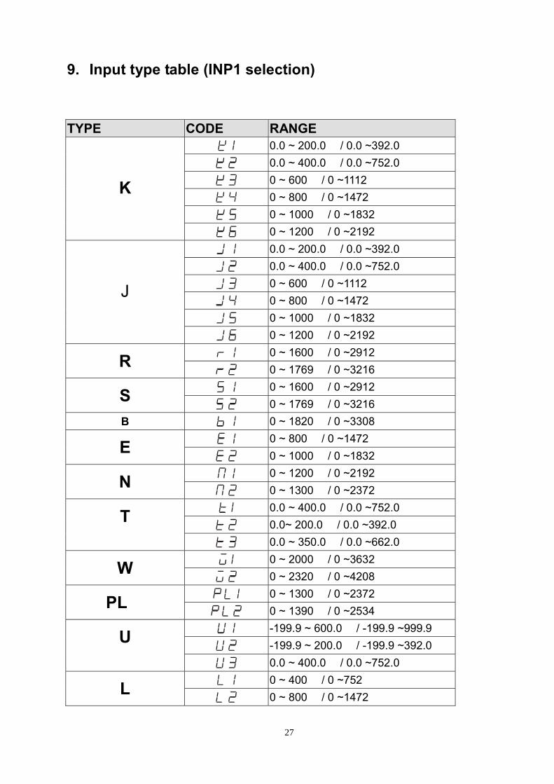
9. Input type table (INP1 selection)
TYPE CODE RANGE
0.0 ~ 200.0 / 0.0 ~392.0
0.0 ~ 400.0 / 0.0 ~752.0
0 ~ 600 / 0 ~1112
0 ~ 800 / 0 ~1472
0 ~ 1000 / 0 ~1832
K
0 ~ 1200 / 0 ~2192
0.0 ~ 200.0 / 0.0 ~392.0
0.0 ~ 400.0 / 0.0 ~752.0
0 ~ 600 / 0 ~1112
0 ~ 800 / 0 ~1472
0 ~ 1000 / 0 ~1832
J
0 ~ 1200 / 0 ~2192
0 ~ 1600 / 0 ~2912 R 0 ~ 1769 / 0 ~3216
0 ~ 1600 / 0 ~2912 S 0 ~ 1769 / 0 ~3216
B 0 ~ 1820 / 0 ~3308
0 ~ 800 / 0 ~1472 E 0 ~ 1000 / 0 ~1832
0 ~ 1200 / 0 ~2192 N 0 ~ 1300 / 0 ~2372
0.0 ~ 400.0 / 0.0 ~752.0
0.0~ 200.0 / 0.0 ~392.0 T
0.0 ~ 350.0 / 0.0 ~662.0
0 ~ 2000 / 0 ~3632 W 0 ~ 2320 / 0 ~4208
0 ~ 1300 / 0 ~2372 PLⅡ 0 ~ 1390 / 0 ~2534
-199.9 ~ 600.0 / -199.9 ~999.9
-199.9 ~ 200.0 / -199.9 ~392.0 U
0.0 ~ 400.0 / 0.0 ~752.0
0 ~ 400 / 0 ~752 L 0 ~ 800 / 0 ~1472

28
TYPE CODE RANGE
-199.9 ~ 600.0 / -199.9 ~999.9
-199.9 ~ 400.0 / -199.9 ~752.0
-199.9 ~ 200.0 / -199.9 ~392.0
0 ~ 200 / 0 ~392
0 ~ 400 / 0 ~752
JIS
PT100
0 ~ 600 / 0 ~1112
-199.9 ~ 600.0 / -199.9 ~999.9
-199.9 ~ 400.0 / -199.9 ~752.0
-199.9 ~ 200.0 / -199.9 ~392.0
0 ~ 200 / 0 ~392
0 ~ 400 / 0 ~752
DIN
PT100
0 ~ 600 / 0 ~1112
-199.9 ~ 600.0 / -199.9 ~999.9
-199.9 ~ 400.0 / -199.9 ~752.0
-199.9 ~ 200.0 / -199.9 ~392.0
0 ~ 200 / 0 ~392
0 ~ 400 / 0 ~752
JIS
PT50
0 ~ 600 / 0 ~1112 AN1 -10 ~ 10mV / -1999~9999 AN2 0 ~ 10mV / -1999~9999 AN3 0 ~ 20mV / -1999~9999 AN4 0 ~ 50mV / -1999~9999 AN5 10 ~ 50mV /-1999~9999
*The initial setting in factory is “K2”.
29
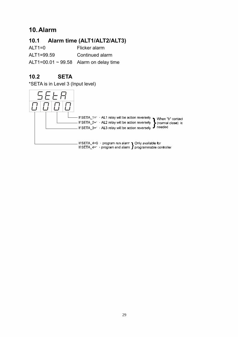
10. Alarm 10.1 Alarm time (ALT1/ALT2/ALT3) ALT1=0 Flicker alarm ALT1=99.59 Continued alarm ALT1=00.01 ~ 99.58 Alarm on delay time 10.2 SETA *SETA is in Level 3 (Input level)
30
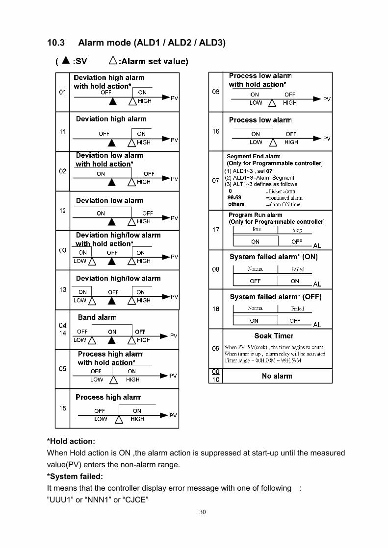
10.3 Alarm mode (ALD1 / ALD2 / ALD3)
*Hold action: When Hold action is ON ,the alarm action is suppressed at start-up until the measured value(PV) enters the non-alarm range. *System failed: It means that the controller display error message with one of following : ”UUU1” or “NNN1” or “CJCE”
31
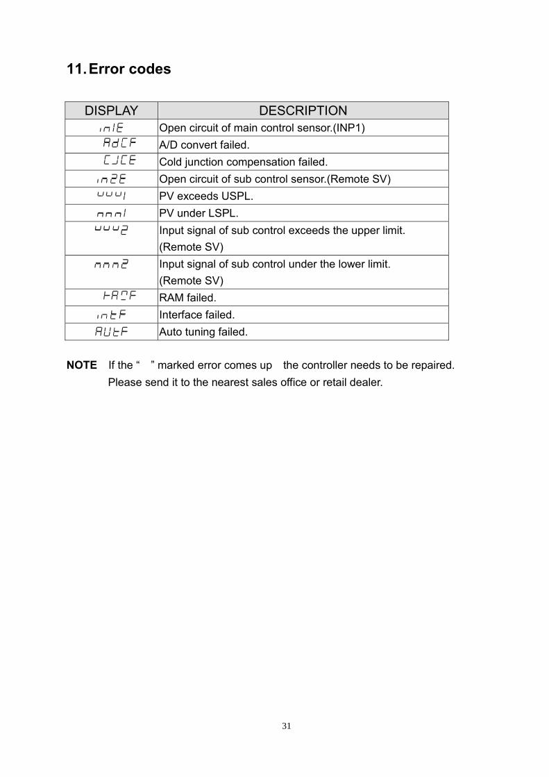
11. Error codes
DISPLAY DESCRIPTION Open circuit of main control sensor.(INP1)
* A/D convert failed. * Cold junction compensation failed.
Open circuit of sub control sensor.(Remote SV) PV exceeds USPL. PV under LSPL.
Input signal of sub control exceeds the upper limit. (Remote SV)
Input signal of sub control under the lower limit. (Remote SV)
* RAM failed.
Interface failed.
Auto tuning failed. NOTE:If the “*” marked error comes up,the controller needs to be repaired.
Please send it to the nearest sales office or retail dealer.
32
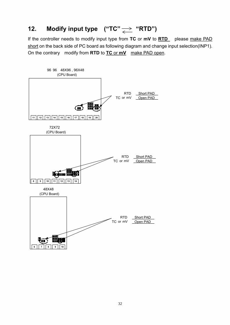
12. Modify input type (“TC” “RTD”) If the controller needs to modify input type from TC or mV to RTD ,please make PAD short on the back side of PC board as following diagram and change input selection(INP1). On the contrary,modify from RTD to TC or mV,make PAD open.
12 13 14 15 16 17 18 19 20
(CPU Board)96×96,48X96 , 96X48
RTD : Short PADTC or mV: Open PAD
8 9 10 11 12 13 14
11
6 7 8 9 10
RTD: Short PADTC or mV: Open PAD
RTD: Short PADTC or mV: Open PAD
(CPU Board)72X72
(CPU Board)48X48
33
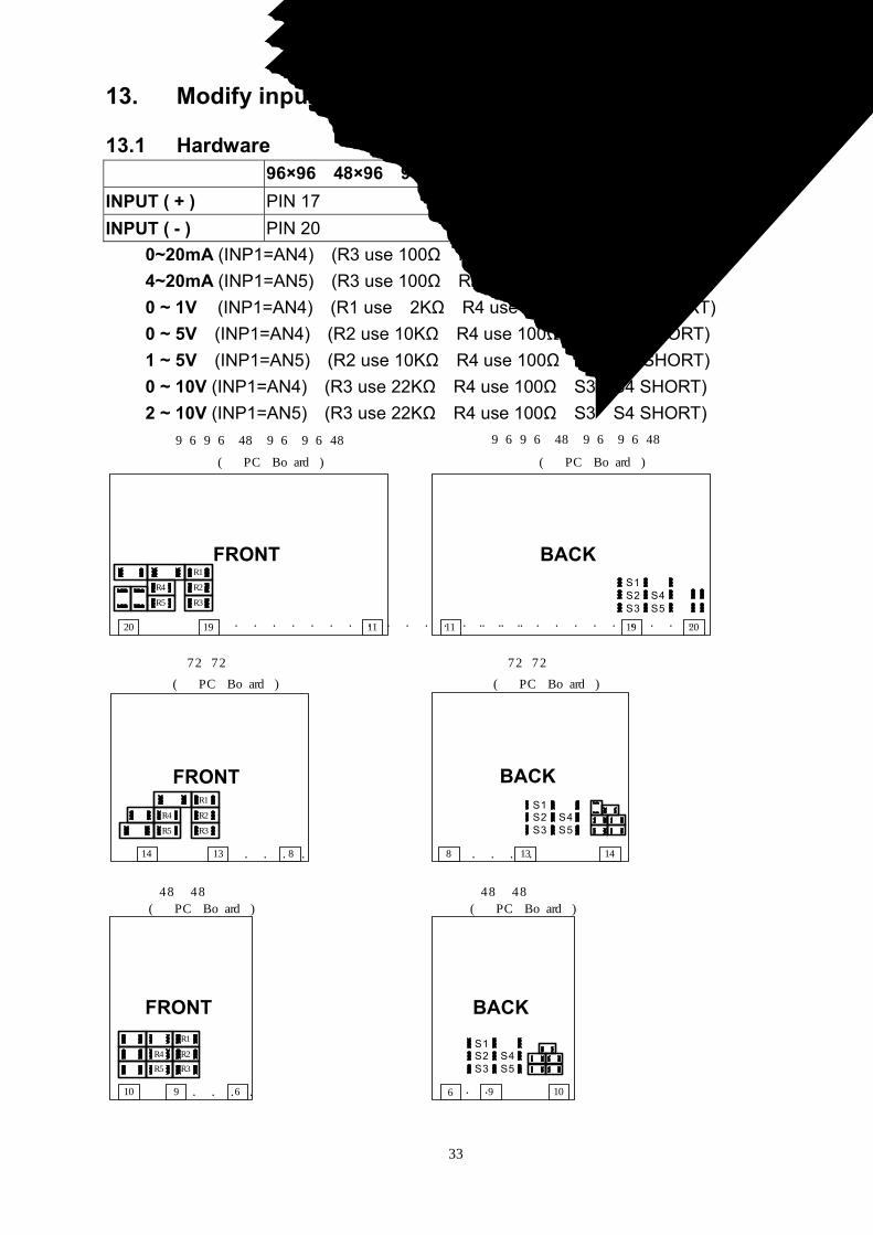
13. Modify input type : Linear Input (mA ,V) 13.1 Hardware: 96×96,48×96,96×48 72×72 48×48 INPUT ( + ) PIN 17 PIN 11 PIN 7 INPUT ( - ) PIN 20 PIN 14 PIN 10
0~20mA (INP1=AN4):(R3 use 100Ω,R5 use 2.4Ω, S3&S5 SHORT) 4~20mA (INP1=AN5):(R3 use 100Ω,R5 use 2.4Ω, S3&S5 SHORT) 0 ~ 1V (INP1=AN4):(R1 use 2KΩ,R4 use 100Ω,S1&S4 SHORT) 0 ~ 5V (INP1=AN4):(R2 use 10KΩ,R4 use 100Ω,S2&S4 SHORT) 1 ~ 5V (INP1=AN5):(R2 use 10KΩ,R4 use 100Ω,S2&S4 SHORT) 0 ~ 10V (INP1=AN4):(R3 use 22KΩ,R4 use 100Ω,S3&S4 SHORT) 2 ~ 10V (INP1=AN5):(R3 use 22KΩ,R4 use 100Ω,S3&S4 SHORT)
BACKFRONT
19 11
( PC Board )
96×96,48×96,96×48
20
FRONT
14 13 8
( PC Board )
FRONT
10 9 6
( PC Board )
48×48
72×72
19 20
( PC Board )
11
BACK
8 13 14
( PC Board )
BACK
9 10
( PC Board )
48×48
72×72
96×96,48×96,96×48
. . . . . . . . . . . . . . . .
R2
R3
R4
R5
R1
. . . . . . . . . . . .
S1S2 S4S3 S5
R2
R3
R4
R5
R1
. . . .
S1S2 S4S3 S5
. . . .
R2
R3
R1
R4
R5
. . . .
S1S2 S4S3 S5
6 . .
34
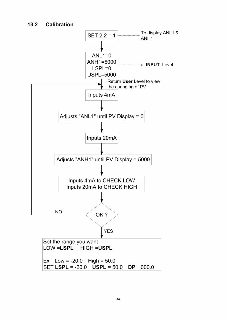
13.2 Calibration:
SET 2.2 = 1
ANL1=0ANH1=5000
LSPL=0USPL=5000
Adjusts "ANL1" until PV Display = 0
Inputs 4mA
Inputs 20mA
Adjusts "ANH1" until PV Display = 5000
Inputs 4mA to CHECK LOWInputs 20mA to CHECK HIGH
OK ?
Set the range you want:LOW =LSPL, HIGH =USPL Ex:Low = -20.0,High = 50.0SET LSPL = -20.0,USPL = 50.0,DP:000.0
To display ANL1 &ANH1
at INPUT Level
Return User Level to viewthe changing of PV
YES
NO
35
14. Modify output type: Relay, SSR, 4~20mA It just needs to change a module at the same position, and modify parameter CYT1 in LEVEL 2 . Relay: CYT1=10, Voltage pulse: CYT1=1, 4~20mA:CYT1=0
15. Modify output mode: OUT1/ALARM, OUT1/OUT2
12 13 14 15 16 17 18 19 20
( CPU Board )
96×96,48×96,96×48
11
PAD of AL3:SHORT
PAD of OUT2:OPEN
12 13 14 15 16 17 18 19 20
( CPU Board )
96×96,48×96,96×48
11
PAD of AL3:OPEN
PAD of OUT2:SHORT
8 9 10 11 12 13 14
( CPU Board )
6 7 8 9 10
( CPU Board )48×48
72×72
PAD of OUT2:OPEN
PAD AL1:SHORT
8 9 10 11 12 13 14
( CPU Board )
72×72
PAD of OUT2:SHORT
PAD of AL1:OPEN
PAD of OUT2:OPEN
PAD of AL1:SHORT
6 7 8 9 10
( CPU Board )48×48
PAD of OUT2:SHORT
PAD of AL1:OPEN
OUT1 / ALARM OUT1 /OUT2
36
16. Applications 16.1 RAMP & SOAK
RAMP: I. SET2.1=1 To display AL3 II. SET4.1=1 To display ALD3 III. ALD3=9 Open RAMP option IV. Then, AL3 will not display. It was replaced by RAMP.
RAMP
0 0.0 0
Range:00.00 ~ 99.99(/ min)(If RAMP is not used,please setALD3 to 0)
SOAK:
I. ALD1 / ALD2=19 To use Sock Timer. II. AL1 / AL2 will display as below:
AL1
0 0 . 0 0Range:00.00 ~ 99.59(Hour.Minute)
Example: SV=100,RAMP=10.00 ( /min) ,AL1=00.10 min,PV=25
100
PV=25
t
5 seccons(Start RAMP function)
Time on
if PV > = SV(100)
Time upAL1 on
SV=PV (When start RAMP function)
SV=SV+RAMP
AL100.10
00.0100.10
Sock Timercounts
1sec.
Power on
37
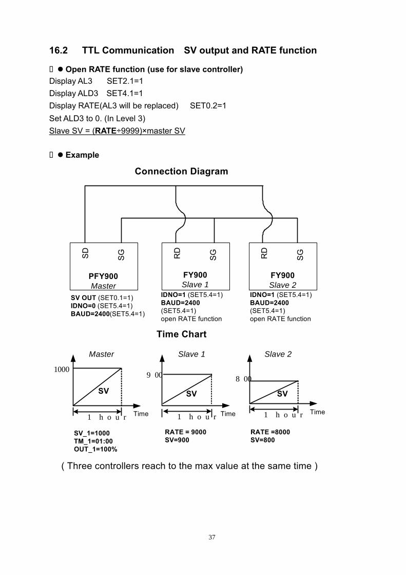
16.2 TTL Communication:SV output and RATE function
Open RATE function (use for slave controller) Display AL3 :SET2.1=1 Display ALD3:SET4.1=1 Display RATE(AL3 will be replaced) :SET0.2=1 Set ALD3 to 0. (In Level 3) Slave SV = (RATE÷9999)×master SV
Example:
SD
SG
PFY900Master
RD
SG
FY900Slave 1
RD
SG
FY900Slave 2
SV OUT (SET0.1=1)IDNO=0 (SET5.4=1)BAUD=2400(SET5.4=1)
IDNO=1 (SET5.4=1)BAUD=2400(SET5.4=1)open RATE function
IDNO=1 (SET5.4=1)BAUD=2400(SET5.4=1)open RATE function
Connection Diagram
Time Chart
Time1 hour
1000
SV_1=1000TM_1=01:00OUT_1=100%
Time1 hour
900
RATE = 9000SV=900
Time1 hour
800
RATE =8000SV=800
( Three controllers reach to the max value at the same time )
SV SV SV
Master Slave 1 Slave 2
38
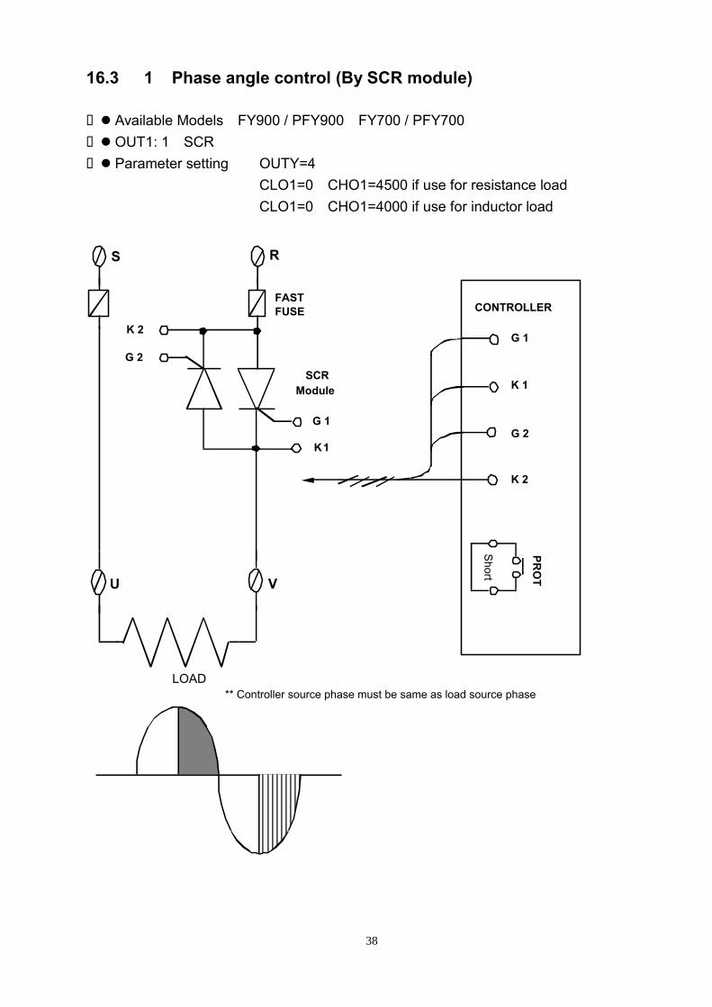
16.3 1ψ Phase angle control (By SCR module)
Available Models:FY900 / PFY900,FY700 / PFY700 OUT1: 1ψSCR Parameter setting: OUTY=4
CLO1=0,CHO1=4500 if use for resistance load CLO1=0,CHO1=4000 if use for inductor load
S
hort
CONTROLLER
G 1
G 2
K 1
K 2
PRO
T
K1
K 2
G 1
S R
G 2
FASTFUSE
U V
SCRModule
** Controller source phase must be same as load source phaseLOAD
39
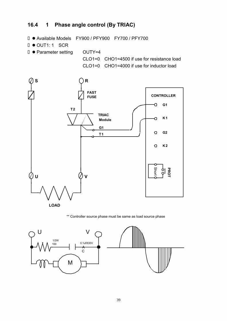
16.4 1ψ Phase angle control (By TRIAC)
Available Models:FY900 / PFY900,FY700 / PFY700 OUT1: 1ψSCR Parameter setting: OUTY=4
CLO1=0,CHO1=4500 if use for resistance load CLO1=0,CHO1=4000 if use for inductor load
Short
CONTROLLER
G1
G2
K1
K2
PRO
T
T1
G1
S R
FASTFUSE
U V
TRIACModule
T2
MM
VU1/2W100Ω 0.1uf/630V
AC
** Controller source phase must be same as load source phase
LOAD
40
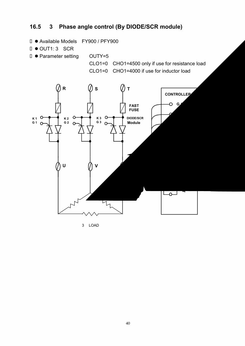
16.5 3ψ Phase angle control (By DIODE/SCR module)
Available Models:FY900 / PFY900 OUT1: 3ψSCR Parameter setting: OUTY=5
CLO1=0,CHO1=4500 only if use for resistance load CLO1=0,CHO1=4000 if use for inductor load
CONTROLLER
Short
K 1G 1
K 2G 2
K 3G 3
TSR
FASTFUSE
U V
DIODE/SCRModule
W
K 2
G 2
K 3
PRO
T
G 3
G 1
3φ LOAD
K 1
41
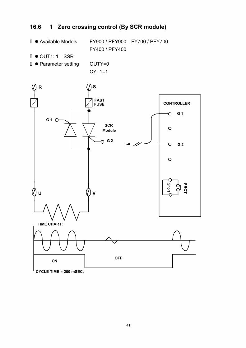
16.6 1ψZero crossing control (By SCR module)
Available Models: FY900 / PFY900,FY700 / PFY700 FY400 / PFY400
OUT1: 1ψSSR Parameter setting: OUTY=0
CYT1=1
Short
G 2
CONTROLLER
G 1
G 2
PRO
T
R S
G 1
FASTFUSE
U V
SCRModule
CYCLE TIME = 200 mSEC.
OFFON
TIME CHART:
42
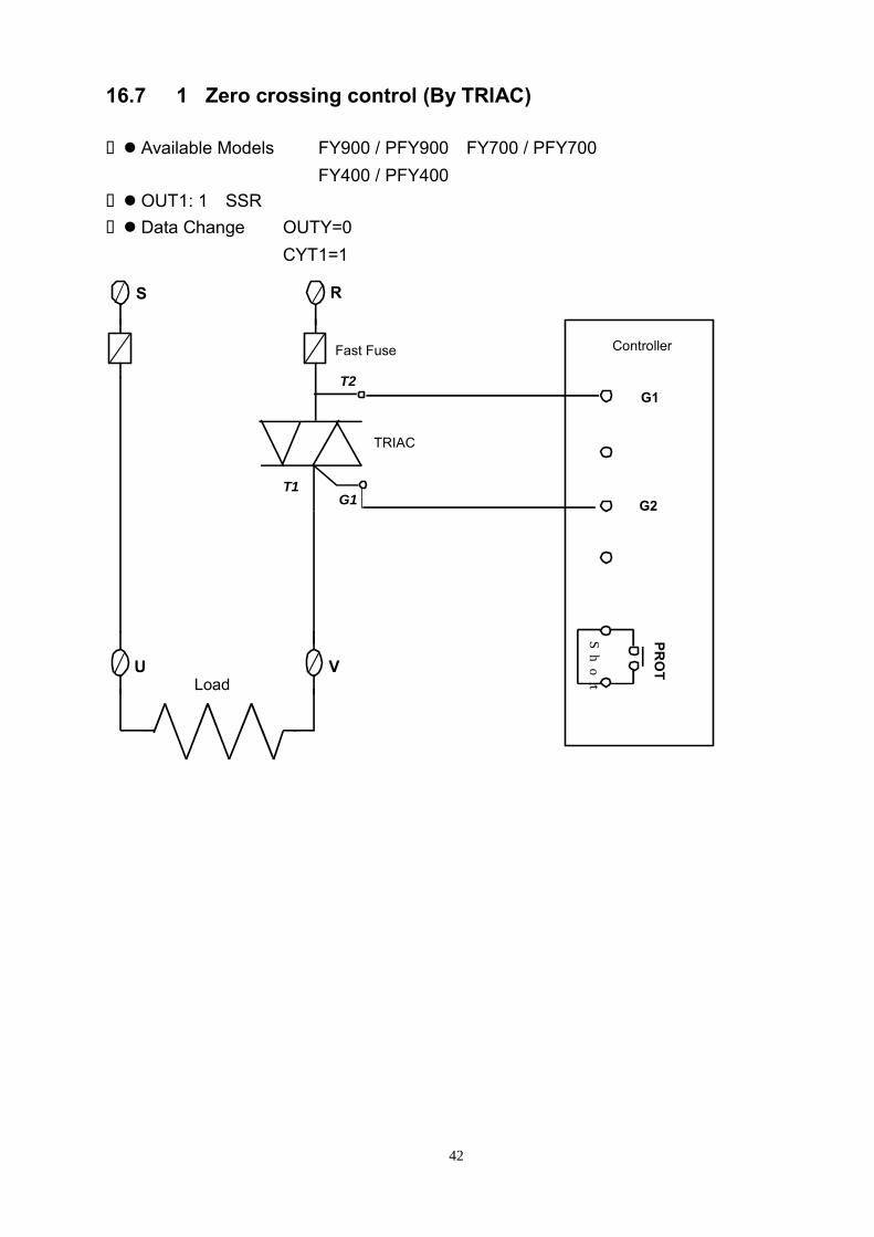
16.7 1ψZero crossing control (By TRIAC)
Available Models: FY900 / PFY900,FY700 / PFY700 FY400 / PFY400
OUT1: 1ψSSR Data Change: OUTY=0
CYT1=1 Short
Controller
G1
G2
PRO
T
T1G1
S R
U V
TRIAC
T2
Load
Fast Fuse

43
16.8 3ψZero crossing control (By SCR module)
Available Models:FY900 / PFY900 OUT1: 3ψSSR Data Change: OUTY=0
CYT1=1
RG 1
Short
CONTROLLER
WE CAN SUPPLYHEATER SINK
RG 1
TG 1
RG 2
TG 2
PRO
T
TG 2
TG 1
SR
FASTFUSE
U V
SCRModule
RG 2
T
W
CYCLE TIME = 200 mSEC.
OFFON
TIME CHART:
44
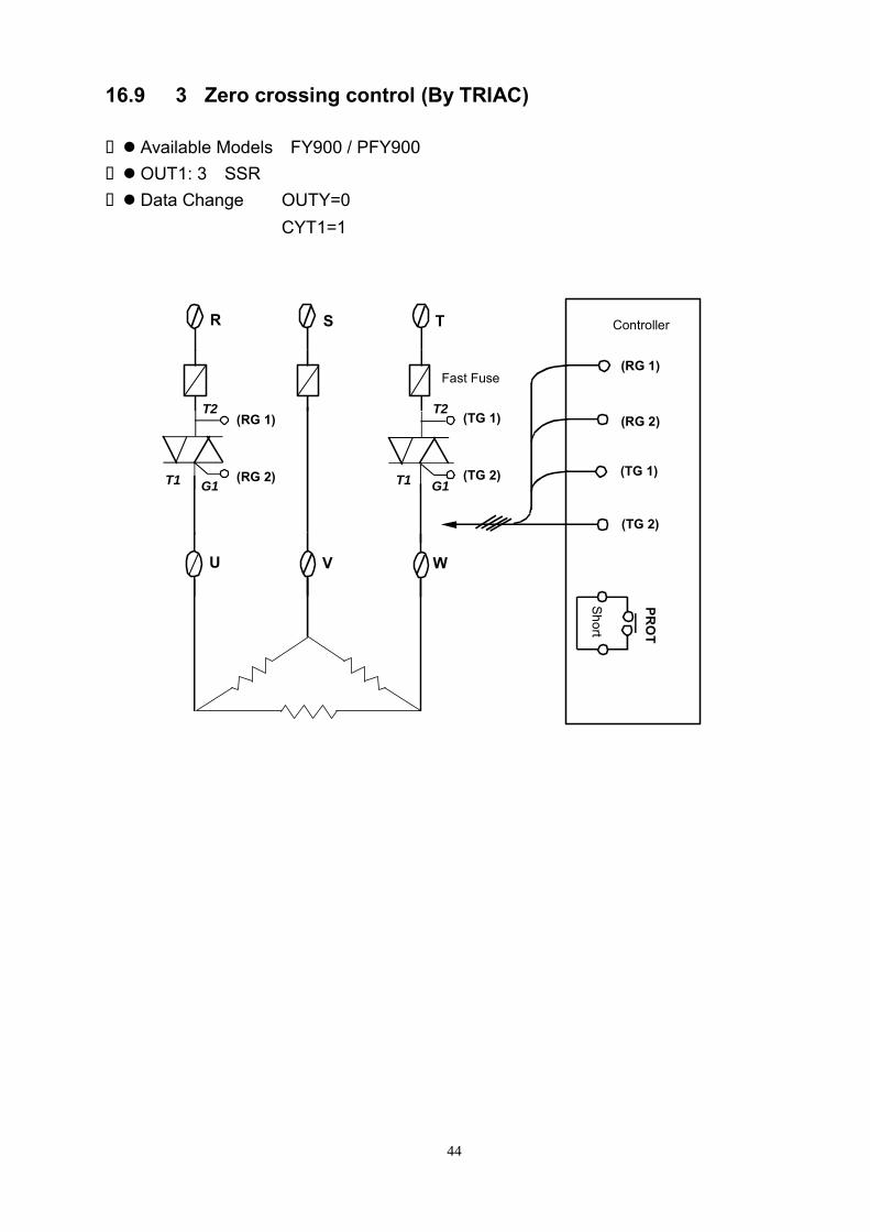
16.9 3ψZero crossing control (By TRIAC)
Available Models:FY900 / PFY900 OUT1: 3ψSSR Data Change: OUTY=0
CYT1=1
Short
Controller
(RG 1)
(TG 1)
(RG 2)
(TG 2)
PRO
T
SR
U V
T
W
Fast Fuse
T2(TG 1)
G1T1 (TG 2)
T2
G1T1
(RG 1)
(RG 2)

45
16.10 3 wires proportional motor valve control
Available Models: FY900 / PFY900,FY700 / PFY700 FY800 / PFY800,FY600 / PFY600 FY400 / PFY400
Data Change: OUTY=3 CYT1=1 ~ 100sec. (Manufacturing default setting “5” seconds.) RUCY=5 ~ 200 seconds.
1. CYT1 is the cycle time of Open / Close 2. RUCY is the 0 ~ 100% running time of motor valve MOTOR VALVE
CONTROLLER
CLOSE
OPEN
COMOPEN
CLOSE
COM
OUT1Relay
OUT2Relay
R
S

46
16.11 Communication 16.11.1 Protocol
Interface RS-232 or RS-485 (by your order) Baud rate 110,300,1200,2400,4800,9600 bps
※Choose by setting parameter “BAUD” in controller.
DATA FRAME Data Bits = 8,ODD Parity,1 Satrt bit,1 Stop bit
0 B0 B1 B2 B3 B4 B5 B6 B7 P 1
DATA FORMAT ※Use “HEX” code data format
NAME DESCRIPTION LENGTHCMD Command 1 BYTE XIDNO The ID of controller 1 BYTE CHNO Reservation,don’t care 1 BYTE XADDR Address 1 BYTE XDATA1 HIGH BYTE of DATA 1 BYTE XDATA2 LOW BYTE of DATA 1 BYTE
CMD R(READ from controller) M(MODIFY the data in controller temporarily)
After controller restarted※ ,the modification will be disappear W(WRITE the data to controller) The HEX CODE of R、M、W are as below R:52H,M:4DH,W:57H。
XIDNO Range:1(01 H)~100(63 H) Must be same as “IDNO“ of the controller※
CHNO Range:(00 H ~ FF H)
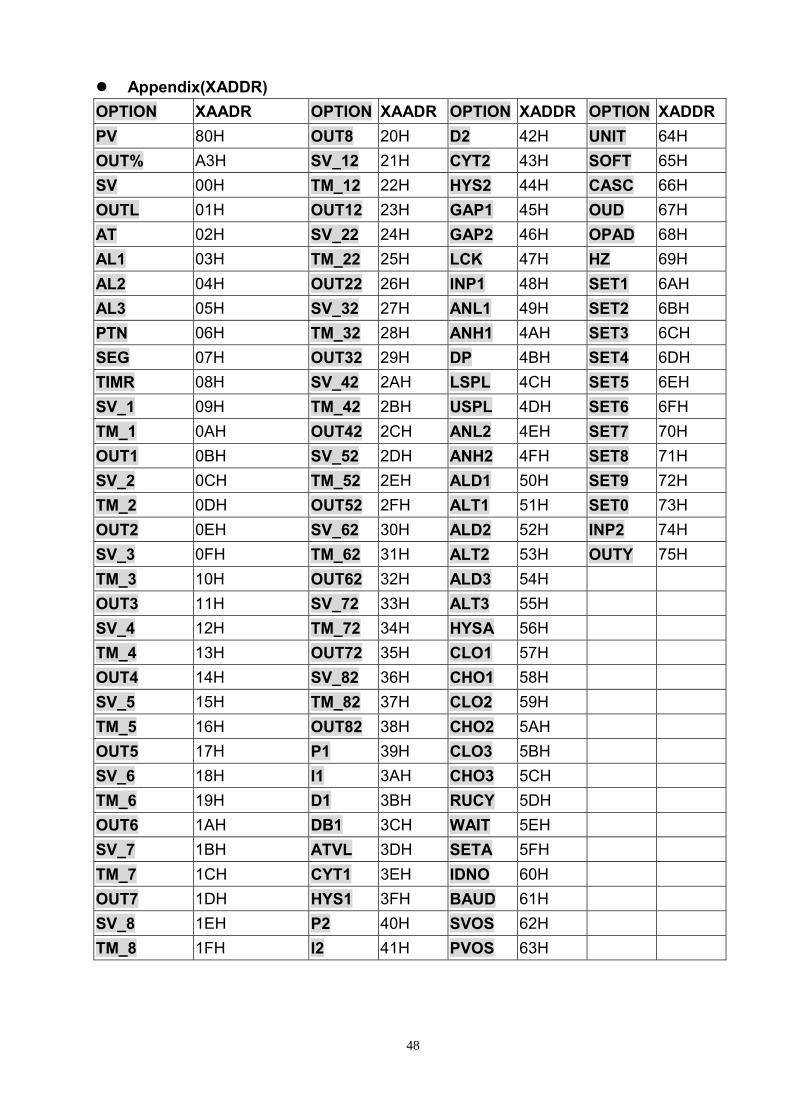
XADDR See Appendix(XADDR)
(Data bits = 8 )
1 Start bit Parity bit
(odd parity) 1 Stop bit
7 Bytes
47
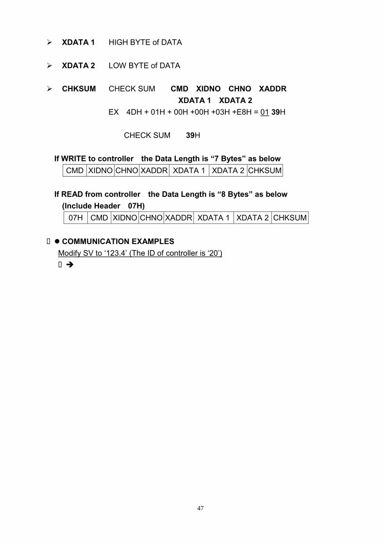
XDATA 1 HIGH BYTE of DATA
XDATA 2 LOW BYTE of DATA
CHKSUM CHECK SUM = CMD+XIDNO+CHNO+XADDR +XDATA 1+XDATA 2
EX:4DH + 01H + 00H +00H +03H +E8H = 01 39H
CHECK SUM = 39H
※If WRITE to controller,the Data Length is “7 Bytes” as below CMD XIDNO CHNO XADDR XDATA 1 XDATA 2 CHKSUM
※If READ from controller,the Data Length is “8 Bytes” as below (Include Header:07H)
07H CMD XIDNO CHNO XADDR XDATA 1 XDATA 2 CHKSUM
COMMUNICATION EXAMPLES Modify SV to ‘123.4’ (The ID of controller is ‘20’)
CMD MODIFY(M):4D H XIDNO 20 (decimal) = 14H(hex) CHNO 00H (Don’t care) XADDR 00 H (The XADDR of SV) XDATA1
& XDATA2 1234(decimal) = 04D2H(hex) CHKSUM 4DH + 14H + 00H +00H +04H +D2H = 0137H
The HEX CODE needed to be send to the controller is ‘4D14 0000 04D2 37’ Read ‘PV’ from controller (The ID of controller is ‘1’)
( CMD READ(R):52 H ( XIDNO 1 (decimal) = 01H(hex) ( CHNO 00H (Don’t care) ( XADDR 80 H (The XADDR of PV) ( XDATA1 & XDATA2 = 0000H ( CHKSUM 52H + 01H + 00H +80H +00H +00H = 00D3H
The HEX CODE needed to be send to the controller is ‘5201 0080 0000 D3’ (Wait about 100ms …) Controller return:07 4D 00 00 00 xxyy zz
Eliminate
PV CHECK SUM=4DH + 00H + 00H + 00H + xxH +yyH(Not Include header 07H)
48
Appendix(XADDR) OPTION XAADR OPTION XAADR OPTION XADDR OPTION XADDRPV 80H OUT8 20H D2 42H UNIT 64H OUT% A3H SV_12 21H CYT2 43H SOFT 65H SV 00H TM_12 22H HYS2 44H CASC 66H OUTL 01H OUT12 23H GAP1 45H OUD 67H AT 02H SV_22 24H GAP2 46H OPAD 68H AL1 03H TM_22 25H LCK 47H HZ 69H AL2 04H OUT22 26H INP1 48H SET1 6AH AL3 05H SV_32 27H ANL1 49H SET2 6BH PTN 06H TM_32 28H ANH1 4AH SET3 6CH SEG 07H OUT32 29H DP 4BH SET4 6DH TIMR 08H SV_42 2AH LSPL 4CH SET5 6EH SV_1 09H TM_42 2BH USPL 4DH SET6 6FH TM_1 0AH OUT42 2CH ANL2 4EH SET7 70H OUT1 0BH SV_52 2DH ANH2 4FH SET8 71H SV_2 0CH TM_52 2EH ALD1 50H SET9 72H TM_2 0DH OUT52 2FH ALT1 51H SET0 73H OUT2 0EH SV_62 30H ALD2 52H INP2 74H SV_3 0FH TM_62 31H ALT2 53H OUTY 75H TM_3 10H OUT62 32H ALD3 54H OUT3 11H SV_72 33H ALT3 55H SV_4 12H TM_72 34H HYSA 56H TM_4 13H OUT72 35H CLO1 57H OUT4 14H SV_82 36H CHO1 58H SV_5 15H TM_82 37H CLO2 59H TM_5 16H OUT82 38H CHO2 5AH OUT5 17H P1 39H CLO3 5BH SV_6 18H I1 3AH CHO3 5CH TM_6 19H D1 3BH RUCY 5DH OUT6 1AH DB1 3CH WAIT 5EH SV_7 1BH ATVL 3DH SETA 5FH TM_7 1CH CYT1 3EH IDNO 60H OUT7 1DH HYS1 3FH BAUD 61H SV_8 1EH P2 40H SVOS 62H TM_8 1FH I2 41H PVOS 63H

49
16.11.2 Wiring diagram
PC
COM PORT :9PIN ( DTE )
SD
SG
RDPin 3 (T)
Pin 2 (R)
Pin 5 (G)
RS232 Connection Diagram
PC
COM PORT :25PIN ( DTE )
Pin 2 (T)
Pin 3 (R)
Pin 7 (G)
NOTE:
1.The length of cable be connected between controller and PC can't exceed 15 meter.
2.One Com Port can only be connected to one controller.If more than one controller is connected to one Com Port,communication will be failed.
3.Ensure that the controller's IDNO and BAUD settings are the same with PC software's settings.
4.For the software communication format please refer to the "Protocol" file in CD.
SD
SG
RD
Controller
Controller
RS485 Connection Diagram
NOTE:1.The length of cable be connected between Converter and Controller can't exceed 1.2 KM.Suggestion:choose "Shielded Cable".
2.One Com Port can be connected up to a maximum of 30 Controllers.
3.Ensure that the Controller's IDNO and BAUD settings are the same with PC software's settings.
4.For the software communication format ,please refer to the "Protocol" file in CD.
PC
Com Port
(Cable)
Converter
DCE
TxONRxO
N
Controller
1234
DX +
DX -
(R-)(T-)
(T+)
(R+)
Cable