fx-smt series operator’s manual - equipco: … smt.pdf71-0085 - rev e 3 introduction...
TRANSCRIPT

FX-SMT SeriesOperator’s Manual
ii 71-0085 - REV E
PROPRIETARY STATEMENT
Thermo GasTech owns proprietary rights in the information disclosed within. By receiving this document, the recipient agrees that neither this document nor the information disclosed within nor any part shall be reproduced or transferred to other documents or used or disclosed to others for manufacturing or for any other purpose except as specifically authorized in writing by Thermo GasTech.
COPYRIGHT STATEMENT
Information contained in this document is protected by copyright. No part of this document may be photocopied, reproduced, or translated to another program or system without prior written authorization from Thermo GasTech., © 2000, Thermo GasTech.
TRADEMARK STATEMENT
Protected through use and/or registration in the United States and many foreign countries are the trademarks and service marks of Thermo GasTech. The use of the ® symbol indicates registration in the United States only; registrations may not have been issued at present in other countries. All other product names and logos are trademarks of their respective owners.
GASTECH® is a trademark of Thermo GasTech and is registered with the U.S. Patent andTrademark Office.
DISCLAIMER
Under no circumstances will Thermo GasTech be liable for any claims, losses, or damages resulting from or arising out of the repair or modification of the equipment by a party other than Thermo GasTech or its authorized service representatives, or by operation or use of the equipment other than in accordance with the printed instructions provided by Thermo GasTech or if the equipment has been improperly maintained or subject to neglect or accident. Any of the foregoing will void the warranty.
EXPORT STATEMENT
Export of the information and products in this manual from the U.S.A., or re-export from another country, may require written authorization from the U.S. Department of Commerce. Printed in the U.S.A.
REVISIONS TO MANUAL
All information contained in this manual is believed to be true and correct at the time of printing. However, as part of its continuing efforts to improve its products and their documentation, Thermo GasTech reserves the right to make changes at any time without notice. Any revised copies of this manual can be obtained by writing Thermo GasTech.

71-0085 - REV E iii
THIS INSTRUMENT IS DESIGNED TO DETECT ONE OR MORE OFTHE FOLLOWING:
FLAMMABLE VAPORS, OXYGEN CONTENT, AND/OR TOXIC GAS AND TOGIVE WARNING BEFORE THEY REACH HARMFUL CONDITIONS. IN ORDERTO ENSURE THAT IT WILL WARN OF DANGEROUS CONCENTRATIONS, ITIS ESSENTIAL THAT THE INSTRUCTIONS IN THIS MANUAL, PARTICULARLYTHOSE CONCERNING START UP, OPERATION, CALIBRATION, ANDMAINTENANCE, BE READ, UNDERSTOOD, AND FOLLOWED.
WARNING
NOTATION CONVENTIONS
Notices are used in this operator’s manual to alert you to hazardous conditions to person or instrument and to notify you of additional information. This operator’s manual uses the following notices.
WARNINGNotifies you of potential danger that can result in personal injury or death.
CAUTIONNotifies you of potential damage to equipment.
NOTENotifies you of additional or critical information.

onal
u. ing)
ave
SERVICE POLICY
Thermo GasTech maintains an instrument service facility at the factory as well as authorized service facilities around the world. Should your instrument require service, you may contact us toll free at 1-877-GASTECH (427-8324) for US only or 1-510-745-8700, or visit our website www.gastech.com for authorized service locations.
For warranty or non-warranty repairs, call us to complete a Return Material Authorization (RMA) form, obtain billing and shipping information and tell us the nature of the problem. For non-warranty repairs, you will need to provide a purchase order number. If you need to set a limit to the repairs costs, state a “Not to Exceed” figure. If you need a quotation before you can authorized the repair costs, so state, but understand this will incur additicosts and may delay processing of the repair.
You may send the unit, prepaid, to: Thermo GasTech, 8407 Central Ave., Newark, CA 94560-3431, Attn.: Service Department. Enclose the copy of the RMA (Return Material Authorization) that was previously faxed to yoPack the instrument and all its accessories (preferably in its original packand any special instructions.
Repairs are warranted for 90 days from the date of shipment. Sensors hindividual warranties.
NOTEThermo GasTech assumes no liability for work performed by unauthorized service facilities.
iv 71-0085 - REV E

,
nd
ial
e
dable
r to ier’s any , in
ster, er,
r
WARRANTY STATEMENT
Thermo GasTech (the “Company”) warrants that the Products will operate substantially in conformance with the Company’s published specificationswhen subjected to normal, proper, and intended usage by properly trainedpersonnel, for a period of one (1) year after shipment to Customer (the “Warranty Period”). The Company agrees during the Warranty Period, provided it is promptly notified in writing upon the discovery of any defect afurther provided that all costs of returning the defective Products to the Company are prepaid by Customer, to repair or replace, at the Company’soption, defective products so as to cause the same to operate in substantconformance with said specifications. Replacement parts may be new or refurbished, at the election of the Company. All replaced parts shall becomthe property of the Company.Lamps, pump diaphragms/valves, batteries, fuses, bulbs, and other expenitems are expressly excluded from the warranty.The Company’s sole liability with respect to equipment, materials, parts, osoftware furnished to the Company by third party suppliers shall be limitedthe assignment by the Company to Customer of any such third-party supplwarranty, to the extent the same is assignable. In no event shall the Comphave any obligation to make repairs, replacements, or corrections requiredwhole or in part, as the result of (i) normal wear and tear, (ii) accident, disaor event of force majeure, (iii) misuse, fault, or negligence of or by Custom(iv) use of the Products in a manner for which they were not designed, (v)causes external to the Products such as, but not limited to, power failure oelectrical power surges, or (vi) use of the Products in combination with equipment or software not supplied by the Company.ANY INSTALLATION, MAINTENANCE, REPAIR, SERVICE, RELOCATION, OR ALTERATION TO OR OF, OR OTHER TAMPERING WITH, THE PRODUCTS PERFORMED BY ANY PERSON OR ENTITY OTHER THAN THE COMPANY WITHOUT THE COMPANY’S PRIOR WRITTEN APPROVAL, OR ANY USE OF REPLACEMENT PARTS NOT SUPPLIED BY THE COMPANY, SHALL IMMEDIATELY VOID AND CANCEL ALL WARRANTIES WITH RESPECT TO THE AFFECTED PRODUCTS.THE OBLIGATION TO REPAIR OR REPLACE A DEFECTIVE PRODUCT SHALL BE THE SOLE REMEDY OF CUSTOMER IN THE EVENT OF A DEFECTIVE PRODUCT. EXCEPT AS EXPRESSLY PROVIDED IN THIS SECTION, THE COMPANY DISCLAIMS ALL WARRANTIES, WHETHER EXPRESS OR IMPLIED, ORAL OR WRITTEN, WITH RESPECT TO THE PRODUCTS, INCLUDING WITHOUT LIMITATION ALL IMPLIED WARRANTIES OF MERCHANTABILITY OR FITNESS FOR ANY PARTICULAR PURPOSE. THE COMPANY DOES NOT WARRANT THAT THE PRODUCTS ARE ERROR-FREE OR WILL ACCOMPLISH ANY PARTICULAR RESULT.
71-0085 - REV E v

vi 71-0085 - REV E

TABLE OF CONTENTS
Chapter 1IntroductionOverview . . . . . . . . . . . . . . . . . . . . . . . . . . . . . . . . . . . . . . . . . . . . . . . . 1Target Gases . . . . . . . . . . . . . . . . . . . . . . . . . . . . . . . . . . . . . . . . . . . . . 2Specifications . . . . . . . . . . . . . . . . . . . . . . . . . . . . . . . . . . . . . . . . . . . . 3
Chapter 2InstallationMounting the FX-SMT . . . . . . . . . . . . . . . . . . . . . . . . . . . . . . . . . . . . . 5Wiring theCombustible Gas Model . . . . . . . . . . . . . . . . . . . . . . . . . . . . 7Wiring the Toxic Gas/Oxygen Models . . . . . . . . . . . . . . . . . . . . . . . . . 9Wiring the Local Alarm Relay. . . . . . . . . . . . . . . . . . . . . . . . . . . . . . . 11Starting Up the FX-SMT . . . . . . . . . . . . . . . . . . . . . . . . . . . . . . . . . . . 11
Chapter 3OperationOverview . . . . . . . . . . . . . . . . . . . . . . . . . . . . . . . . . . . . . . . . . . . . . . . 13Normal Operation . . . . . . . . . . . . . . . . . . . . . . . . . . . . . . . . . . . . . . . . 13Alarm Indications . . . . . . . . . . . . . . . . . . . . . . . . . . . . . . . . . . . . . . . . 14Responding to Alarm Indications . . . . . . . . . . . . . . . . . . . . . . . . . . . . 15Storing New Parameters . . . . . . . . . . . . . . . . . . . . . . . . . . . . . . . . . . . 16
Chapter 4CalibrationCalibration Kit . . . . . . . . . . . . . . . . . . . . . . . . . . . . . . . . . . . . . . . . . . . 23Preparing for Calibration . . . . . . . . . . . . . . . . . . . . . . . . . . . . . . . . . . 24Non-Intrusive Calibration . . . . . . . . . . . . . . . . . . . . . . . . . . . . . . . . . . 25
Chapter 5MaintenancePreventive Maintenance . . . . . . . . . . . . . . . . . . . . . . . . . . . . . . . . . . . 29Troubleshooting . . . . . . . . . . . . . . . . . . . . . . . . . . . . . . . . . . . . . . . . . 29Replacing the Detector . . . . . . . . . . . . . . . . . . . . . . . . . . . . . . . . . . . . 32Returning for Repair . . . . . . . . . . . . . . . . . . . . . . . . . . . . . . . . . . . . . . 33
71-0085 - REV E vii
FX-SMT Operator’s Manual
Appendix AParts List . . . . . . . . . . . . . . . . . . . . . . . . . . . . . . . . . . . . . . . . . . . . . . . 35
Appendix BInternal CalibrationPreparing for Calibration . . . . . . . . . . . . . . . . . . . . . . . . . . . . . . . . . . 39Calibrating the FX-SMT . . . . . . . . . . . . . . . . . . . . . . . . . . . . . . . . . . . 40
Appendix CLocal Alarm Relay Module . . . . . . . . . . . . . . . . . . . . . . . . . . . . . . . . . 43
viii 71-0085 - REV E

Chapter1
INTRODUCTION
o
A
at il
Overview
The FX-SMT is a series of single-point combustible gas, oxygen, or toxic gas monitors.The oxygen and toxic gas models each include two versions:
• FX-SMT: Suitable for Class I, Division 1, Groups B, C, and D hazardous locations.
• FX-SMTn: Suitable for non-hazardous locations only.
NOTEUnless otherwise specified, all references to the “FX-SMT” apply tboth versions.
The FX-SMT displays the current gas reading and transmits a 4 to 20 msignal output that is proportional to the range of detection. The FX-SMT warns you of hazardous gas concentration conditions with visual alarmstwo preset alarm levels. Alarm outputs for low alarm, high alarm, and faconditions are also available (combustible gas version only).
71-0085 - REV E 1

FX-SMT Operator’s Manual
Target Gases
Table 1-1 lists detection ranges and default alarm points for the FX-SMT gas monitor.
Table 1-1 FX-SMT Target Gases and Detection Ranges
Target GasDetection
RangeLow
AlarmHigh
Alarm
Hydrocarbons 0 to 100% LELor
0-5000 ppmor
0-5.00%
10% LEL
500 ppm
0.5%
50% LEL
1000 ppm
2.5%
Oxygen 0 to 30.0% O2 19.5% O2 23.5% O2
Ammonia 0 to 100 ppm 25 ppm 35 ppm
Arsine 0 to 1.00 ppm 0.05 ppm 0.1 ppm
Diborane 0 to 1.00 ppm 0.1 ppm 0.5 ppm
Carbon monoxide 0 to 500 ppm 25 ppm 200 ppm
Chlorine 0 to 10.0 ppm 0.5 ppm 1.0 ppm
Chlorine dioxide 0 to 2.00 ppm 0.1 ppm 0.3 ppm
Fluorine 0 to 10.0 ppm 1 ppm 2 ppm
Hydrogen chloride 0 to 30.0 ppm 5 ppm 10 ppm
Hydrogen cyanide 0 to 50.0 ppm 4.7 ppm 10 ppm
Hydrogen fluoride 0 to 10.0 ppm 3 ppm 5 ppm
Hydrogen sulfide 0 to 100 ppm 10 ppm 15 ppm
Nitric oxide 0 to 100 ppm 25 ppm 75 ppm
Nitrogen dioxide 0 to 20.0 ppm 3 ppm 5 ppm
Ozone 0 to 1.00 ppm 0.1 ppm 0.5 ppm
Phosphine 0 to 1.00 ppm 0.3 ppm 0.5 ppm
Silane 0 to 50.0 ppm 5 ppm 15 ppm
Sulfur dioxide 0 to 20.0 ppm 2 ppm 5 ppm
2 71-0085 - REV E

Introduction
Specifications
Table 1-2 lists the FX-SMT’s performance, physical, electrical, and environmental specifications.
Table 1-2 Specifications
Signal Output 4 to 20 mA
Alarm Delay Setting 3 seconds1
Sampling Method Diffusion
Linearity ± 5% of detection range
Repeatability ± 3% of detection range
Housing Copper-free aluminum
Dimensions FX-SMT (toxic/oxygen versions) 12.75 in. (32.4 cm) H x 5.5 in. (14.0 cm) W x 4.53 in. D (11.5 cm)
FX-SMT (combustible version)7.5 in. (19.1 cm) Hx 5.5 in. (14.0 cm) W x 4.53 in. D (11.5 cm)
FX-SMTn (toxic/oxygen versions)8.5 in. (21.6 cm) H x 5.5 in. (14.0 cm) W x 4.53 in. D (11.5 cm)
Weight (approximate)
5 lbs. (2.3 kg)
Enclosure Rating NEMA 3, 4, 7, and 9(SMT versions only)2
Area Classification Class I, Division 1,Groups B, C, and D environments(SMT versions only)2, 3
Power Source 10 to 28 VDC
Temperature Range -4°F (-20°C) to 113°F (45°C)
Humidity Range 0 to 95% RH (non-condensing)
1 Default setting, but adjustable in Setup program.2 The SMTn versions for oxygen and toxic gas detection do not include the
components necessary for location in Class I, Division 1 hazardous locations.3 The hydrocarbon version is suitable for Class I, Division 1, Group A, B, C, and
D locations.
71-0085 - REV E 3

FX-SMT Operator’s Manual
4 71-0085 - REV E

Chapter2
INSTALLATION
near
ew
WARNINGPerform all installation procedures in a fresh air environment (known to be free of combustible and toxic gases and of normal oxygen content). The FX-SMT is not in operation as a gas monitoring system until the start-up procedure is complete.
Mounting the FX-SMT1. Select the mounting area. When you select the mounting area,
consider the following:
• Is the display screen visible?
• Is there enough room to:
– mount the housing? (see Figures 2-1 or 2-2)
– remove the housing cover?
– make wiring connections through the top conduit hub?
– attach the test cup to the detector during the calibration procedure?
• Is the mounting location representative of the monitoring environment? Light gases rise to the ceiling; heavy gases settle the floor.
2. Secure the housing to the vertical surface with a 1/4 in. bolt or scrthrough each mounting lug (see Figures 2-1 or 2-2).
71-0085 - REV E 5

FX-SMT Operator’s Manual
Figure 2-1 FX-SMT Outline and Mounting Dimensions
Figure 2-2 FX-SMTn Outline and Mounting Dimensions
Notes:
GASTECH
FX-SERIES
HC 0 % LEL
1. Housing is 4.53" [11.5 cm] deep.2. Weight is 5 lbs [2.3 kg].
9.0"[22.9 cm]
5.5"[14.0 cm]
5.5"[14.0 cm]
5.5"[14.0 cm]
12.75"[32.4 cm]
5.5"[14.0 cm]
Oxygen/Toxic Gas Versions
5.5"[14.0 cm]
8.5"[21.6 cm]
.27" Dia2 Places
Notes:1. Housing is 4.53" [11.5 cm] deep.2. Weight is 5 lbs [2.3 kg].
5.5"[14.0 cm]
3/4" NPT
6 71-0085 - REV E

Installation
Wiring the Combustible Gas Model
WARNINGMake connections at the FX-SMT terminal strip before you plug in or turn on the DC power. Before making any wiring adjustments, always verify that the DC power source is not live.
1. Unscrew the cover from the FX-SMT housing.
2. Remove the display assembly by grasping it and gently pulling up. (Make sure the ribbon cable remains connected to the display assembly and main board.)
3. Verify that the detector leads are connected to the sensor terminal strip as shown in Figure 2-3. The 3-point sensor terminal strip is attached to the sensor board, above the main board.
WARNINGFollow electrical codes for installing electrical conduit and wiring for hazardous locations. (Refer to NFPA 70, article 501.)
Seal conduit to prevent intrusion of moisture of conduit into the FX-SMT housing.
In locations classified as “hazardous” (National Electric Code article 500) and with power on, the area must be certified “gas-free” before you remove the housing cover. Consult prevailing national, local, and corporate requirements for certification.
4. Run three conductors through the top conduit hub of the FX-SMT housing.
NOTETo reduce Radio Frequency Interference (RFI) and Electro-magnetic Interference (EMI), use shielded cable or run wiring within metal conduit. Always ground the cable or conduit at the receiver or controller and not at the FX-SMT.
5. Connect the conductors to the power/signal terminal strip (TB1) on the main board as shown in Figures 2-3 and 2-4.
71-0085 - REV E 7
FX-SMT Operator’s Manual
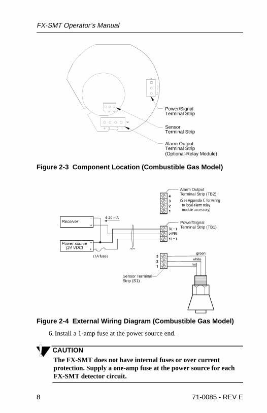
Figure 2-3 Component Location (Combustible Gas Model)
Figure 2-4 External Wiring Diagram (Combustible Gas Model)
6. Install a 1-amp fuse at the power source end.
CAUTIONThe FX-SMT does not have internal fuses or over current protection. Supply a one-amp fuse at the power source for each FX-SMT detector circuit.
Alarm OutputTerminal Strip
Power/SignalTerminal Strip
Terminal StripSensor
(Optional-Relay Module)
(See Appendix C for wiring to local alarm relay module accessory)
Alarm OutputTerminal Strip (TB2)
Power/SignalTerminal Strip (TB1)
Sensor TerminalStrip (S1)
8 71-0085 - REV E
Installation
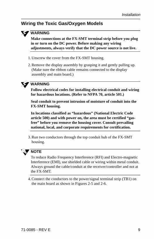
Wiring the Toxic Gas/Oxygen Models
WARNINGMake connections at the FX-SMT terminal strip before you plug in or turn on the DC power. Before making any wiring adjustments, always verify that the DC power source is not live.
1. Unscrew the cover from the FX-SMT housing.
2. Remove the display assembly by grasping it and gently pulling up. (Make sure the ribbon cable remains connected to the display assembly and main board.)
WARNINGFollow electrical codes for installing electrical conduit and wiring for hazardous locations. (Refer to NFPA 70, article 501.)
Seal conduit to prevent intrusion of moisture of conduit into the FX-SMT housing.
In locations classified as “hazardous” (National Electric Code article 500) and with power on, the area must be certified “gas-free” before you remove the housing cover. Consult prevailing national, local, and corporate requirements for certification.
3. Run two conductors through the top conduit hub of the FX-SMT housing.
NOTETo reduce Radio Frequency Interference (RFI) and Electro-magnetic Interference (EMI), use shielded cable or wiring within metal conduit. Always ground the cable/conduit at the receiver/controller and not at the FX-SMT.
4. Connect the conductors to the power/signal terminal strip (TB1) on the main board as shown in Figures 2-5 and 2-6.
71-0085 - REV E 9
FX-SMT Operator’s Manual
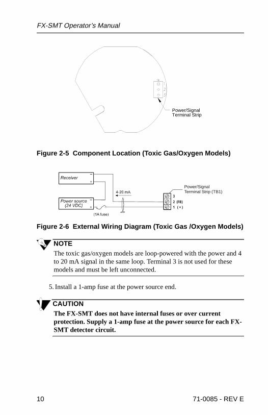
Figure 2-5 Component Location (Toxic Gas/Oxygen Models)
Figure 2-6 External Wiring Diagram (Toxic Gas /Oxygen Models)
NOTEThe toxic gas/oxygen models are loop-powered with the power and 4 to 20 mA signal in the same loop. Terminal 3 is not used for these models and must be left unconnected.
5. Install a 1-amp fuse at the power source end.
CAUTIONThe FX-SMT does not have internal fuses or over current protection. Supply a 1-amp fuse at the power source for each FX-SMT detector circuit.
Terminal StripPower/Signal
1 ( + )2 (FB)
3
Power/SignalTerminal Strip (TB1)
10 71-0085 - REV E

Installation
l
ples
.
FX-
to
Wiring the FX-SMT to the Local Alarm Relay Module (Combustible Gas Model Only)
WARNINGMake connections at the local alarm relay module before you plug in or turn on the DC power. Before making any wiring adjustments, always verify that the DC power source is not live.
1. At the FX-SMT, verify that the detector leads are connected to the sensor terminal strip as shown in Figure 2-4.
2. Wire the local alarm relay module to the FX-SMT’s power terminastrip as shown in Appendix C.
Starting Up the FX-SMT
NOTEThe display screens illustrated in this section are intended as examonly any may appear slightly different than your FX-SMT model.
1. Complete the mounting and wiring procedures described earlier inthis chapter.
2. Verify that all wiring connections are correct and secure.
3. Plug in or turn on the incoming DC power at the power source end
If the display screen is blank, the FX-SMT is not receiving power. Check the DC power connections at the power source and at the SMT’s main board, then begin the start-up procedure again.The following message displays.
The FX-SMT counts down from 30 seconds,
then the normal screen displays.
NOTEAlthough the normal screen displays, the FX-SMT may require upone hour to warm up and for the display reading to stabilize.
haG s T e c V X X.X
paW r m U 3 s c .0 se
pCH U L L0 E%
71-0085 - REV E 11
FX-SMT Operator’s Manual
12 71-0085 - REV E

Chapter3
OPERATION
g
er or
Overview
This chapter describes the FX-SMT gas monitor in normal operation, alarms and how to respond to them. The section at the end of this chapter describes how to enter the Setup program and update FX-SMT parameters.
Normal Operation
Normal operation is defined as any time the start-up procedure is complete and the FX-SMT is not indicating a low alarm, high alarm, or fail condition.
Display Reading
While in normal operation, the FX-SMT monitors the environment and displays the current gas concentration in %LEL (combustible gas model), PPM (toxic gas model), or % volume (oxygen model). The combustible gas model may also be configured to display in ppm or % volume.
Signal Output
While in normal operation, the range of the signal output from the FX-SMT’s power/signal terminal strip is 4 to 20 mA. The range is directly proportional to the range of detection for the target gas. Use the followinformula to determine the target gas concentration from the signal outputreading.Concentration = (mA - 4)/16 x (fullscale concentration)
EXAMPLE
Range: 0 to 100%LELOutput: 12 mA
12 - 4 = 88/16 = 0.50.5 x 100 = 50%LEL
NOTEThe LEL model of the FX-SMT may respond to combustible gasesother than the target gas, and the readings produced may be highlower than the actual gas concentration.
71-0085 - REV E 13

FX-SMT Operator’s Manual
ct
Alarm Indications
NOTEThe low and high alarm points and alarm delay setting are adjustable in the Setup program.
Low Alarm Condition
When the display reading reaches the preset low alarm point, the FX-SMT recognizes a low alarm condition.If the condition exists for a longer period of time than the low alarm delay setting, the right side of the display screen alternates between the current gas reading and the message Low Alarm. For the combustible gas model, the backlight will also alternate from on to off, and the alarm LED will flash.
High Alarm Condition
When the display reading reaches the preset high alarm point, the FX-SMT recognizes a high alarm condition.If the condition exists for a longer period of time than the high alarm delay setting, the right side of the display screen alternates between the current gas reading and the message High Alarm. For the combustible gas model, the backlight will also alternate from on to off, and the alarm LED will flash
Fail Condition
The FX-SMT recognizes a fail condition if one or more of the following conditions exist:
• The wiring from the detector to the sensor terminal strip is incorreor disconnected.
• The detector is malfunctioning.
In fail condition, the signal output is 3.5 mA.
14 71-0085 - REV E

Operation
Responding to Alarm Indications
Low Alarm Condition
1. Follow the established procedure for a low level combustible or toxic gas condition or a decreasing oxygen content condition. If a procedure is not in place, establish one that is appropriate for your application.
NOTEThe Alarm Latch setting is adjustable in the Setup program. The default setting is Off.
2. If the Alarm Latch setting is Off: When the reading falls below the low alarm point for a period of time longer than the alarm reset delay, the FX-SMT automatically resets the low alarm circuit.
If the Alarm Latch setting is On: You must manually reset the low alarm circuit. Place the magnetic wand against the dome cover, and swipe it from right to left over the magnetic sensor located just above the display screen.
If the condition has cleared, Reset displays and the low alarm circuit is reset. If the condition has not cleared, Reset Failed displays and the low alarm indications continue.
High Alarm Condition
1. Follow the established procedure for a high level combustible or toxic gas condition or an increasing oxygen content condition. If a procedure is not in place, establish one that is appropriate for your application.
2. If the Alarm Latch setting is off: When the reading falls below the high alarm point for a period of time longer than the alarm reset delay, the FX-SMT automatically resets the high alarm circuit.
If the Alarm Latch setting is on: You must manually reset the high alarm circuit. Place the magnetic wand against the dome cover, and swipe it from right to left over the magnetic sensor located just above the display screen.
If the condition has cleared, Reset displays and the high alarm circuit is reset. If the condition has not cleared, Reset Failed displays and the high alarm indications continue.
Fail Condition
1. Recalibrate the FX-SMT as described in Chapter 4, Calibration.
2. If the fail condition continues, contact Thermo GasTech for further instruction.
71-0085 - REV E 15

FX-SMT Operator’s Manual
e T
ress
Storing New Parameters
You can display, adjust, and store the following parameters in the Setup program.
• Range (display only)
• Calibration gas value
• Low alarm point
• High alarm point
• Alarm delay
• Calibration time limit (days)
• Low/High alarm latch (on/off)
• Relay drive output (normally energized/de-energized)
• Low alarm activation (rise/fall)
• High alarm activation (rise/fall)
• Fault alarm latch (on/off)
• Calibration reminder (on/off)
• Gas display units (display only for toxic gas/oxygen)
• Detector voltage adjust (combustible gas model only)
• Air value (display only)
• Span value (display only)
Making Adjustments and Saving in the Setup Program
• To save current settings (including settings you updated during thecurrent session), press the ENTER or RUN/SETUP button until thSaving... message displays. If you press RUN/SETUP, the FX-SMreturns to the normal screen after saving is complete.
• To adjust a setting, press and hold the RUN/SETUP button, then pthe UP or DOWN button. Pressing and holding the UP or DOWN button will produce a faster scroll rate.
• To proceed to the next screen, press the UP button until the next screen displays.
• To return to the previous screen, press the DOWN button until theprevious screen displays.
• To return to the normal screen, press and hold the RUN/SETUP button until the normal screen displays.
16 71-0085 - REV E
Operation
.
Operating the Setup Program
NOTEThe display screens illustrated in this section are intended as examples only and may appear slightly different than your FX-SMT model.
Perform the following procedure to enter the Setup program and display or adjust the parameters.
ENTERING THE SETUP PROGRAM
1. Unscrew the cover from the FX-SMT housing.
WARNINGIn locations classified as “hazardous” (National Electric Code article 500) and with power on, the area must be certified “gas-free” before you remove the housing cover. Consult prevailing national, local, and corporate requirements for certification.
2. Press and hold the RUN/SETUP button for four seconds to enter the Setup program.
The signal output of the FX-SMT is 3.5 mA when it is in the Setup program.
NOTEThe FX-SMT automatically returns to RUN mode5 minutes from the last time you pressed one of the adjustment buttons.
DISPLAYING THE FULL SCALE SETTING
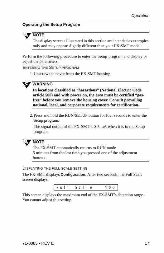
The FX-SMT displays Configuration. After two seconds, the Full Scale screen displays.
This screen displays the maximum end of the FX-SMT’s detection rangeYou cannot adjust this setting.
l l S c a l eu 1 0 0F
71-0085 - REV E 17

FX-SMT Operator’s Manual
DISPLAYING/ADJUSTING THE CALIBRATION VALUE
3. From the Full Scale screen, press the UP button until the Calibration Value screen displays.
This screen displays the value to which the FX-SMT adjusts the response setting during the Non-intrusive (external) or Internal Calibration programs.
WARNINGThis setting must match the concentration of the calibration sample.
DISPLAYING/ADJUSTING THE LOW ALARM POINT
4. From the Calibration Value screen, press the UP button until the Low Alarm screen displays.
This screen displays the reading at which the FX-SMT recognizes a low alarm condition.
DISPLAYING/ADJUSTING THE HIGH ALARM POINT
5. From the Low Alarm screen, press the UP button until the High Alarm screen displays.
This screen displays the reading at which the FX-SMT recognizes a high alarm condition.
DISPLAYING/ADJUSTING THE ALARM DELAY SETTING
6. From the High Alarm screen, press the UP button until the Alarm Delay screen displays.
This screen displays the period of time (in seconds) that the FX-SMT delays indication of an alarm once the FX-SMT recognizes the condition.
WARNINGThe alarm circuits are inactive for the length of the alarm delay setting and will not warn you of possible hazardous gas conditions.
l G a sa 5 0C
w A l a r mo 1 0L
g h A l a r mi 5 0H
a r m D e l a yl 3A
18 71-0085 - REV E

Operation
lay
s ).
rm
DISPLAYING/ADJUSTING THE CALIBRATION INTERVAL
7. From the Alarm Delay screen, press the UP button until the Calibration Interval screen displays.
This screen displays the time (in days) between required calibration. The minimum setting is 0; the maximum setting is 100.For example, if the setting is 30, on the 30th day from the last calibration, the FX-SMT begins periodically displaying the Cal Reminder message during normal operation.The calibration reminder feature is turned on or off from the Calibration Reminder screen, which displays later in the Setup program.
DISPLAYING/ADJUSTING ALARM LATCHING
8. From the Calibration Interval screen, press the UP button until the Alarm Latching screen displays.
This screen determines how alarm circuits are reset once an alarm condition passes.With alarm latching Off, the FX-SMT automatically resets its alarm circuits. With alarm latching On, you must manually reset the alarm circuit (see “Responding to Alarm Indications”).
DISPLAYING/ADJUSTING RELAY ACTIVATION
9. From the Alarm Latching screen, press the UP button until the Rescreen displays.
This screen determines whether the drive circuit for the external relays inormally de-energized (Norm Open) or normally energized (Norm Close
DISPLAYING/ADJUSTING LOW ALARM ACTIVATION
10. From the Relay screen, press the UP button until the Low Alarm Activation screen displays.
This screen determines if the FX-SMT recognizes a low alarm conditionwhen the gas reading rises above (Rise) or falls below (Fall) the low alapoint.
NOTEThe default setting for the oxygen model is Fall.
l T i m ea 3 0C
t c h i n ga O f fL
l pa y N o r m Oe e nR
w RA l a r mo i s eL
71-0085 - REV E 19
FX-SMT Operator’s Manual
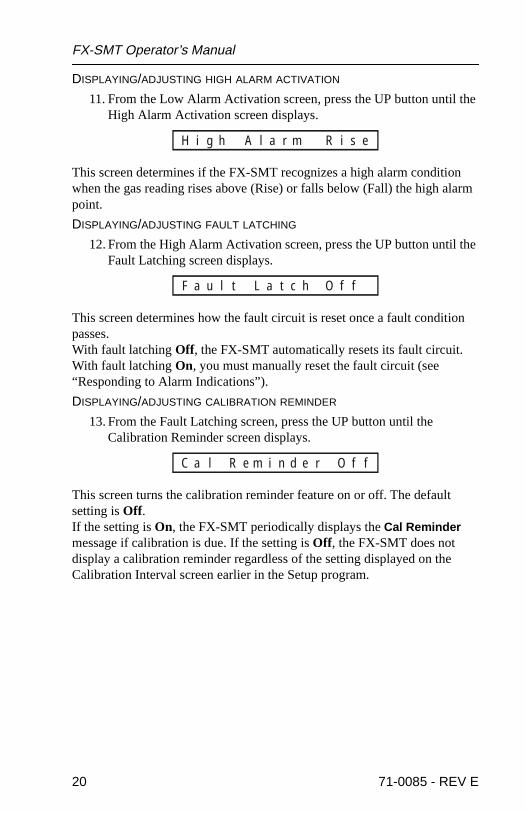
DISPLAYING/ADJUSTING HIGH ALARM ACTIVATION
11. From the Low Alarm Activation screen, press the UP button until the High Alarm Activation screen displays.
This screen determines if the FX-SMT recognizes a high alarm condition when the gas reading rises above (Rise) or falls below (Fall) the high alarm point.
DISPLAYING/ADJUSTING FAULT LATCHING
12. From the High Alarm Activation screen, press the UP button until the Fault Latching screen displays.
This screen determines how the fault circuit is reset once a fault condition passes.With fault latching Off, the FX-SMT automatically resets its fault circuit. With fault latching On, you must manually reset the fault circuit (see “Responding to Alarm Indications”).
DISPLAYING/ADJUSTING CALIBRATION REMINDER
13. From the Fault Latching screen, press the UP button until the Calibration Reminder screen displays.
This screen turns the calibration reminder feature on or off. The default setting is Off.If the setting is On, the FX-SMT periodically displays the Cal Reminder message if calibration is due. If the setting is Off, the FX-SMT does not display a calibration reminder regardless of the setting displayed on the Calibration Interval screen earlier in the Setup program.
g Rh A l a r mi i s eH
u Ol t L a t c ha f fF
l R e m i n d e ra O f fC
20 71-0085 - REV E

Operation
p l
be he
sured
DISPLAYING/ADJUSTING DISPLAY UNITS
14. From the Calibration Reminder screen, press the UP button until the Display Units screen displays.
This screen indicates the unit of measure that the FX-SMT displays on the normal screen. For the toxic gas and oxygen models, you cannot adjust this setting.For the combustible gas model, the gas reading units can be displayed as ppm (parts per million), % VOL (% by volume), or % LEL (lower explosive limit).
WARNINGIf the units are changed, the SMT will require recalibration (see Chapter 4). The alarm settings will automatically be reset to the values shown in Table 1-1.
DISPLAYING/ADJUSTING SENSOR VOLTAGE (COMBUSTIBLE GAS MODEL ONLY)
15. From the Display Units screen, press the UP button until the “Adj. Uor Down” screen displays (see below). The screen with then scrolautomatically to the HC Volts screen. The HC sensor voltage is factory set, and does not require routine adjustment. It should onlyadjusted if the sensor is mounted remote from the SMT housing. Tadjustment should be made so that the voltage at the sensor (meaat Red and Green leads) is 6.0 volts.
WARNINGImproper adjustment of the HC sensor voltage can cause the sensor to become unresponsive to combustible gases, and may also damage the sensor.
i %t sn L E LU
#V o l t sC # # #H
j o. U p o r Dd w nA
71-0085 - REV E 21

FX-SMT Operator’s Manual
DISPLAYING DIAGNOSTIC AND FACTORY-SET SCREENS
16. From the HC Volts screen, press the UP button to display the following screens. These screens are for diagnostic or factory-setting purposes and are not intended for user adjustment.
EXITING THE SETUP PROGRAM
17. Press the RUN/SETUP button until the Saving... message or normal screen displays.
The Saving... message only displays if you made changes in the Setup program.
18. Screw the cover onto the FX-SMT housing.
a #n #p # # #S
r #i # # #A
22 71-0085 - REV E
Chapter4
CALIBRATION
n n-
the
)
le to
Two calibration procedures are available for the FX-SMT gas monitor.• Non-intrusive calibration is an external procedure that allows you to
calibrate the FX-SMT without removing the housing cover. You caavoid de-classifying hazardous environments if you perform the nointrusive calibration procedure. This chapter describes the non-intrusive calibration procedure.
• The internal calibration procedure allows you to calibrate the FX-SMT if the magnetic wand is not available or to adjust the value of calibration gas setting. Appendix B, Internal Calibration, describesthe internal calibration procedure.
WARNINGAccurate calibration of the FX-SMT is essential to ensure accurate readings of the target gas. Incorrect calibration can impair the FX-SMT’s performance and place you in unnecessary danger if hazardous conditions exist.
Calibration Kit
The calibration kit contains all of the equipment you need to introduce a calibration gas sample to the detector. It includes the following components:
• Storage Case (safely stores the components of the calibration kit.
• Cylinder (contains a known concentration of the target gas.)
• Regulator (controls the flow of the sample from the cylinder to thedetector.)
• Test Cup (attaches to the detector and allows the calibrating sampflow past the detector.)
• Tubing (connects components of the calibration kit.)
71-0085 - REV E 23
FX-SMT Operator’s Manual
’s
Preparing for Calibration
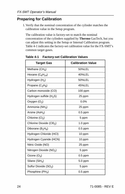
1. Verify that the nominal concentration of the cylinder matches the calibration value in the Setup program.
The calibration value is factory-set to match the nominal concentration of the cylinders supplied by Thermo GasTech, but you can adjust this setting in the Setup or Internal Calibration program. Table 4-1 indicates the factory-set calibration value for the FX-SMTcommon target gases.
Table 4-1 Factory-set Calibration Values
Target Gas Calibration Value
Methane (CH4) 50%LEL
Hexane (C6H14) 40%LEL
Hydrogen (H2) 50%LEL
Propane (C3H8) 45%LEL
Carbon monoxide (CO) 100 ppm
Hydrogen sulfide (H2S) 25 ppm
Oxygen (O2) 0.0%
Ammonia (NH3) 25 ppm
Arsine (AsH3) 0.5 ppm
Chlorine (Cl2) 5 ppm
Chlorine Dioxide (Cl02) 1.0 ppm
Diborane (B2H6) 0.5 ppm
Hydrogen Chloride (HCl) 10 ppm
Hydrogen Cyanide (HCN) 10 ppm
Nitric Oxide (NO) 25 ppm
Nitrogen Dioxide (NO2) 5 ppm
Ozone (O3) 0.5 ppm
Silane (SiH4) 5.0 ppm
Sulfur Dioxide (SO2) 5 ppm
Phosphine (PH3) 0.5 ppm
24 71-0085 - REV E

Calibration
t
e a ero-
ion lay .
2. Verify that the flow control valve on the regulator is closed, then carefully screw the regulator onto the cylinder.
NOTEIf possible, calibrate the FX-SMT with the same gas as the target gas.
3. Attach the sample tubing over the male end of the regulator. Verify that the connection is tight and secure.
4. Slide the test cup over the detector, then secure the cup to the detector.
5. Use the sample tubing to connect the regulator to the test cup.
6. Verify that all tubing connections are tight and secure.
Non-Intrusive Calibration
WARNINGThe FX-SMT is not an active gas monitor during the calibration procedure. The signal output is 3.5 mA while the FX-SMT is in Calibration mode.
Verify that the calibrating environment is suitable for maintenance activity before you begin the calibration procedure.
1. Assemble the calibration kit.
2. Verify that the FX-SMT is in RUN mode. If theFX-SMT is in SETUP mode, wait until it automatically returns to RUN mode (maximum of5 minutes).
3. Verify that the FX-SMT is in a “fresh air” environment (environmenknown to be free of the target gas and of normal oxygen content).
NOTEIf you cannot verify the absence of the target gas in the calibratingenvironment, you will need a zero-emission air cylinder to introducgas-free sample to the detector (see Appendix A, Parts List.) The zemission air cylinder is not part of the standard calibration kit.
4. A magnetic wand is used to access and step through the Calibratprogram. Locate the magnetic sensor, which is mounted to the disppanel. It is the black cylinder located just above the display screen
71-0085 - REV E 25
FX-SMT Operator’s Manual
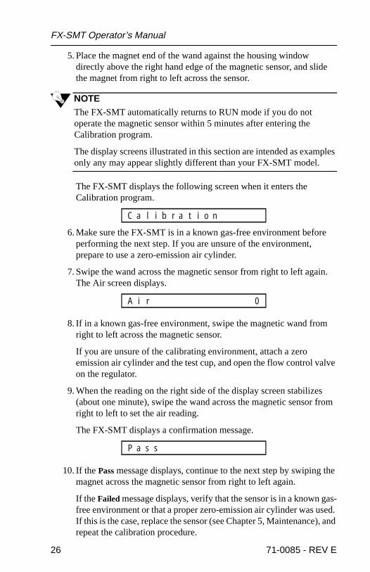
5. Place the magnet end of the wand against the housing window directly above the right hand edge of the magnetic sensor, and slide the magnet from right to left across the sensor.
NOTEThe FX-SMT automatically returns to RUN mode if you do not operate the magnetic sensor within 5 minutes after entering the Calibration program.
The display screens illustrated in this section are intended as examples only any may appear slightly different than your FX-SMT model.
The FX-SMT displays the following screen when it enters the Calibration program.
6. Make sure the FX-SMT is in a known gas-free environment before performing the next step. If you are unsure of the environment, prepare to use a zero-emission air cylinder.
7. Swipe the wand across the magnetic sensor from right to left again. The Air screen displays.
8. If in a known gas-free environment, swipe the magnetic wand from right to left across the magnetic sensor.
If you are unsure of the calibrating environment, attach a zero emission air cylinder and the test cup, and open the flow control valve on the regulator.
9. When the reading on the right side of the display screen stabilizes (about one minute), swipe the wand across the magnetic sensor from right to left to set the air reading.
The FX-SMT displays a confirmation message.
10. If the Pass message displays, continue to the next step by swiping the magnet across the magnetic sensor from right to left again.
If the Failed message displays, verify that the sensor is in a known gas-free environment or that a proper zero-emission air cylinder was used. If this is the case, replace the sensor (see Chapter 5, Maintenance), and repeat the calibration procedure.
l i b r a t i o naC
ri 0A
s saP
26 71-0085 - REV E
Calibration
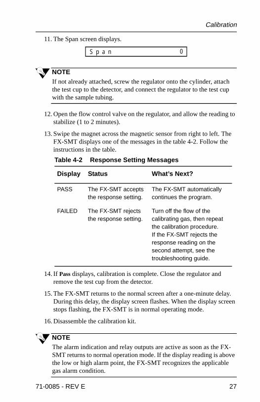
11. The Span screen displays.
NOTEIf not already attached, screw the regulator onto the cylinder, attach the test cup to the detector, and connect the regulator to the test cup with the sample tubing.
12. Open the flow control valve on the regulator, and allow the reading to stabilize (1 to 2 minutes).
13. Swipe the magnet across the magnetic sensor from right to left. The FX-SMT displays one of the messages in the table 4-2. Follow the instructions in the table.
14. If Pass displays, calibration is complete. Close the regulator and remove the test cup from the detector.
15. The FX-SMT returns to the normal screen after a one-minute delay. During this delay, the display screen flashes. When the display screen stops flashing, the FX-SMT is in normal operating mode.
16. Disassemble the calibration kit.
NOTEThe alarm indication and relay outputs are active as soon as the FX-SMT returns to normal operation mode. If the display reading is above the low or high alarm point, the FX-SMT recognizes the applicable gas alarm condition.
Table 4-2 Response Setting Messages
Display Status What’s Next?
PASS The FX-SMT accepts the response setting.
The FX-SMT automatically continues the program.
FAILED The FX-SMT rejects the response setting.
Turn off the flow of the calibrating gas, then repeat the calibration procedure.If the FX-SMT rejects the response reading on the second attempt, see the troubleshooting guide.
a 0pS n
71-0085 - REV E 27

FX-SMT Operator’s Manual
28 71-0085 - REV E
Chapter5
MAINTENANCE
WARNINGIf possible, perform all maintenance activities in a non-hazardous environment.
Preventive Maintenance
This schedule describes procedures to ensure the performance and durability of the FX-SMT gas monitor.
Daily
1. Verify that the display is on. If the display is off, see the Troubleshooting table.
2. Investigate significant changes in the display reading and signal output.
Monthly
Calibrate the FX-SMT as described in Chapter 4, Calibration, or Appendix B, Internal Calibration.
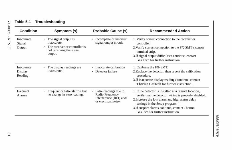
Troubleshooting
The following troubleshooting guide describes symptoms, probable causes, and recommended actions for problems you may encounter with the FX-SMT gas monitor.
71-0085 - REV E 29

3071-0085 - R
EV
E
FX
-SM
T O
perator’s Manual
Ta
Recommended Action
FC
spond as described in “Responding to Alarm ications”.
N rify correct connections at the power source.ify that the display board is connected to the in board by the ribbon cable.ify correct connections at the FX-SMT’swer/signal terminal strip.ower failure continues, contact Thermo sTech for further instruction.
CF
rify that you are using a correct test cylinder and t it has an adequate supply of the test sample.
peat the calibration procedure.alibration difficulties continue, replace the tector, then calibrate the new detector.alibration failure continues, contact Thermo sTech for further instruction.
ble 5-1 Troubleshooting
Condition Symptom (s) Probable Cause (s)
ailondition
• The FAIL message is displayed.
• The signal output is 3.5 mA.
• Incorrect detector wiring
• Detector failure• Microprocessor failure
1. ReInd
o Power • The display screen is blank.• The signal output is 0.0 mA.
• Incomplete or incorrect power circuit.
• Display board is disconnected.
1. Ve2.Ver
ma3.Ver
po4.If p
Ga
alibrationailure
• The display screen indicates FAIL when you confirm a zero or response setting during the calibration procedure.
• Sample in test cylinder is low or exhausted
• Detector failure
1. Vetha
2.Re3.If c
de4.If c
Ga
71-0085 - RE
V E
31
Maintenance
ISO
rify correct connection to the receiver or ntroller.ify correct connection to the FX-SMT’s sensor minal strip.ignal output difficulties continue, contact s Tech for further instruction.
IDR
librate the FX-SMT.place the detector, then repeat the calibration cedure.accurate display readings continue, contactermo GasTech for further instruction.
FA
he detector is installed at a remote location, rify that the detector wiring is properly shielded.rease the low alarm and high alarm delay ttings in the Setup program.uspect alarms continue, contact Thermo sTech for further instruction.
Ta
Recommended Action
naccurateignalutput
• The signal output is inaccurate.
• The receiver or controller is not receiving the signal output.
• Incomplete or incorrect signal output circuit.
1. Veco
2.Verter
3.If sGa
naccurateisplayeading
• The display readings are inaccurate.
• Inaccurate calibration• Detector failure
1. Ca2.Re
pro3.If in
Th
requentlarms
• Frequent or false alarms, but no change in zero reading.
• False readings due to Radio Frequency Interference (RFI) and/or electrical noise.
1. If tve
2.Incse
3.If sGa
ble 5-1 Troubleshooting
Condition Symptom (s) Probable Cause (s)
FX-SMT Operator’s Manual
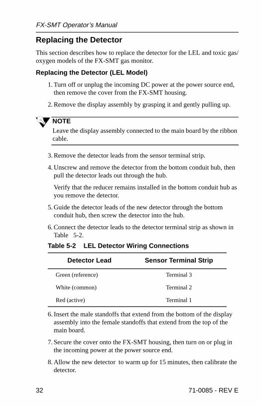
Replacing the Detector
This section describes how to replace the detector for the LEL and toxic gas/oxygen models of the FX-SMT gas monitor.
Replacing the Detector (LEL Model)
1. Turn off or unplug the incoming DC power at the power source end, then remove the cover from the FX-SMT housing.
2. Remove the display assembly by grasping it and gently pulling up.
NOTELeave the display assembly connected to the main board by the ribbon cable.
3. Remove the detector leads from the sensor terminal strip.
4. Unscrew and remove the detector from the bottom conduit hub, then pull the detector leads out through the hub.
Verify that the reducer remains installed in the bottom conduit hub as you remove the detector.
5. Guide the detector leads of the new detector through the bottom conduit hub, then screw the detector into the hub.
6. Connect the detector leads to the detector terminal strip as shown in Table 5-2.
6. Insert the male standoffs that extend from the bottom of the display assembly into the female standoffs that extend from the top of the main board.
7. Secure the cover onto the FX-SMT housing, then turn on or plug in the incoming power at the power source end.
8. Allow the new detector to warm up for 15 minutes, then calibrate the detector.
Table 5-2 LEL Detector Wiring Connections
Detector Lead Sensor Terminal Strip
Green (reference) Terminal 3
White (common) Terminal 2
Red (active) Terminal 1
32 71-0085 - REV E

Maintenance
Replacing the Sensor (Toxic Gas/Oxygen Models)
1. Turn off or unplug the incoming DC power at the power source end.
2. Push and turn the sensor housing counterclockwise to disconnect the locking pins from the tabs in the cap.
3. Gently pull the cap off the sensor housing. There may be some resistance due to the o-ring at the top of the cap.
4. Unplug the sensor from the sensor board. Note which sockets the sensor was plugged into.
5. Plug in the new sensor, then replace the cap.
6. Turn on or plug in the incoming power at the power source end.
7. Allow the new sensor to stabilize for at least one hour, then calibrate the sensor.
Returning for Repair
Before you remove the FX-SMT from the monitoring area, first contact a Thermo GasTech representative.The Thermo GasTech representative may guide you through certain diagnostic procedures with the FX-SMT in place. If you cannot correct the malfunction, the representative will assist you in returning the FX-SMT for repair.
71-0085 - REV E 33

FX-SMT Operator’s Manual
34 71-0085 - REV E

AppendixA
Parts List
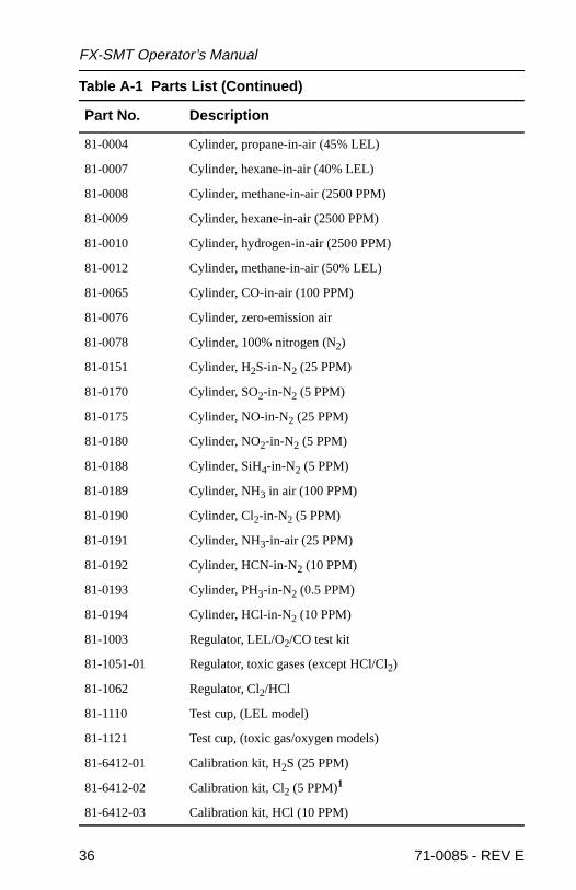
Table A-1 lists part numbers for the FX-SMT gas monitor’s replacementparts and accessories.
Table A-1 Parts List
Part No. Description
25-0106 Housing cover
45-4533-01 Terminal strip, 3-position
45-4534-01 Terminal strip, 4-position
57-7631 Local alarm relay module
61-0101 Sensor, hydrocarbon (HC)
65-1061 Sensor, oxygen (O2)
65-2420-02 Sensor, sulfur dioxide (SO2)
65-2425-01 Sensor, carbon monoxide (CO)
65-2425-02 Sensor, hydrogen sulfide (H2S)
65-2431-01 Sensor, chlorine (Cl2)/fluorine (F2)
65-2431-02 Sensor, hydrogen cyanide (HCN)
65-2431-03 Sensor, nitric oxide (NO)
65-2431-04 Sensor, hydrogen chloride (HCl)
65-2431-05 Sensor, hydrogen fluoride (HF)
65-2431-07 Sensor, ammonia (NH3) (low range)
65-2431-08 Sensor, phosphine (PH3)/arsine (AsH3)/silane (SiH4)/diborane (B2H6)
65-2431-09 Sensor, ozone (O3)
65-2431-10 Sensor, nitrogen dioxide (NO2)
65-2431-11 Sensor, chlorine dioxide (ClO2)
65-2431-12 Sensor, ammonia (NH3) ( high range)
71-0085 FX-SMT Series Operator’s Manual
81-0002 Cylinder, hydrogen-in-air (50% LEL)
71-0085 - REV E 35
FX-SMT Operator’s Manual
81-0004 Cylinder, propane-in-air (45% LEL)
81-0007 Cylinder, hexane-in-air (40% LEL)
81-0008 Cylinder, methane-in-air (2500 PPM)
81-0009 Cylinder, hexane-in-air (2500 PPM)
81-0010 Cylinder, hydrogen-in-air (2500 PPM)
81-0012 Cylinder, methane-in-air (50% LEL)
81-0065 Cylinder, CO-in-air (100 PPM)
81-0076 Cylinder, zero-emission air
81-0078 Cylinder, 100% nitrogen (N2)
81-0151 Cylinder, H2S-in-N2 (25 PPM)
81-0170 Cylinder, SO2-in-N2 (5 PPM)
81-0175 Cylinder, NO-in-N2 (25 PPM)
81-0180 Cylinder, NO2-in-N2 (5 PPM)
81-0188 Cylinder, SiH4-in-N2 (5 PPM)
81-0189 Cylinder, NH3 in air (100 PPM)
81-0190 Cylinder, Cl2-in-N2 (5 PPM)
81-0191 Cylinder, NH3-in-air (25 PPM)
81-0192 Cylinder, HCN-in-N2 (10 PPM)
81-0193 Cylinder, PH3-in-N2 (0.5 PPM)
81-0194 Cylinder, HCl-in-N2 (10 PPM)
81-1003 Regulator, LEL/O2/CO test kit
81-1051-01 Regulator, toxic gases (except HCl/Cl2)
81-1062 Regulator, Cl2/HCl
81-1110 Test cup, (LEL model)
81-1121 Test cup, (toxic gas/oxygen models)
81-6412-01 Calibration kit, H2S (25 PPM)
81-6412-02 Calibration kit, Cl2 (5 PPM)1
81-6412-03 Calibration kit, HCl (10 PPM)
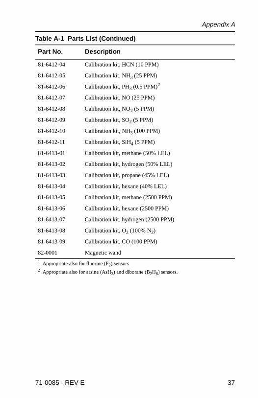
Table A-1 Parts List (Continued)
Part No. Description
36 71-0085 - REV E
Appendix A
81-6412-04 Calibration kit, HCN (10 PPM)
81-6412-05 Calibration kit, NH3 (25 PPM)
81-6412-06 Calibration kit, PH3 (0.5 PPM)2
81-6412-07 Calibration kit, NO (25 PPM)
81-6412-08 Calibration kit, NO2 (5 PPM)
81-6412-09 Calibration kit, SO2 (5 PPM)
81-6412-10 Calibration kit, NH3 (100 PPM)
81-6412-11 Calibration kit, SiH4 (5 PPM)
81-6413-01 Calibration kit, methane (50% LEL)
81-6413-02 Calibration kit, hydrogen (50% LEL)
81-6413-03 Calibration kit, propane (45% LEL)
81-6413-04 Calibration kit, hexane (40% LEL)
81-6413-05 Calibration kit, methane (2500 PPM)
81-6413-06 Calibration kit, hexane (2500 PPM)
81-6413-07 Calibration kit, hydrogen (2500 PPM)
81-6413-08 Calibration kit, O2 (100% N2)
81-6413-09 Calibration kit, CO (100 PPM)
82-0001 Magnetic wand
1 Appropriate also for fluorine (F2) sensors2 Appropriate also for arsine (AsH3) and diborane (B2H6) sensors.
Table A-1 Parts List (Continued)
Part No. Description
71-0085 - REV E 37

FX-SMT Operator’s Manual
38 71-0085 - REV E

AppendixB
Internal Calibration
ich ot
e a ero-
This appendix describes the FX-SMT’s internal calibration procedure, whrequires you to remove the housing cover. See Chapter 4, Calibration, tperform the non-intrusive calibration procedure.
WARNINGCalibrate the FX-SMT in a “fresh air” environment (known to be free of gas and of normal oxygen content).
Preparing for Calibration1. Assemble the Calibration kit.
2. Verify that the FX-SMT is in a “fresh air” environment (environmenknown to be free of the target gas and of normal oxygen content).
NOTEIf you cannot verify the absence of the target gas in the calibratingenvironment, you will need a zero-emission air cylinder to introducgas-free sample to the detector (see Appendix A, Parts List.) The zemission air cylinder is not part of the standard calibration kit.
WARNINGIn locations classified as “hazardous” (National Electric Code article 500) and with power on, the area must be certified “gas-free” before you open the junction box cover. Consult prevailing national, local, and corporate requirements for certification.
3. Remove the cover from the FX-SMT housing.
NOTEThe display screens illustrated in this section are intended as examples only any may appear slightly different than your FX-SMT model.
71-0085 - REV E 39

FX-SMT Operator’s Manual
Calibrating the FX-SMT1. Press the UP and DOWN buttons simultaneously for two seconds to
enter the Calibration program. TheFX-SMT displays the following screen when it enters the Calibration program,
then the Air screen displays.
2. Make sure the FX-SMT is in a known gas-free environment before performing the next step. If you are unsure of the environment, prepare to use azero-emission air cylinder.
3. If in a known gas-free environment, press the ENTER button and go to step 5.
If you are unsure of the calibrating environment, attach a zero emission air cylinder and test cup, and open the flow control valve on the regulator.
4. When the reading on the right side of the display screen stabilizes (about one minute), press the ENTER button to set the air reading. The FX-SMT displays a Pass message, then the Span screen displays.
If the Failed message displays, verify the sensor is in a known gas-free environment or that a proper zero-emission air cylinder was used. If this is the case, replace the sensor, and repeat the calibration procedure.
5. Open the flow control valve on the regulator, and allow the reading to stabilize (1 to 2 minutes).
6. Press the ENTER button. The FX-SMT displays one of the messages in the table B-1. Follow the instructions in the table.
l i b r a t i o naC
ri 0A
a 0pS n
40 71-0085 - REV E
Appendix B
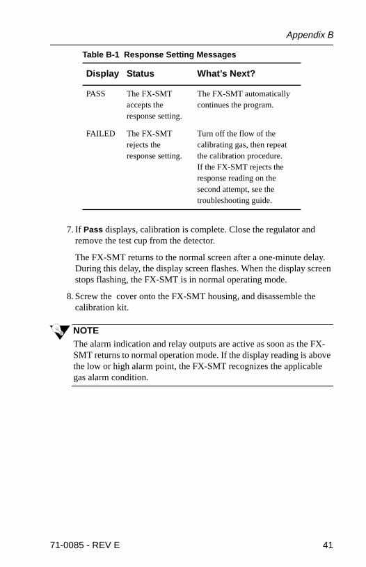
7. If Pass displays, calibration is complete. Close the regulator and remove the test cup from the detector.
The FX-SMT returns to the normal screen after a one-minute delay. During this delay, the display screen flashes. When the display screen stops flashing, the FX-SMT is in normal operating mode.
8. Screw the cover onto the FX-SMT housing, and disassemble the calibration kit.
NOTEThe alarm indication and relay outputs are active as soon as the FX-SMT returns to normal operation mode. If the display reading is above the low or high alarm point, the FX-SMT recognizes the applicable gas alarm condition.
Table B-1 Response Setting Messages
Display Status What’s Next?
PASS The FX-SMT accepts the response setting.
The FX-SMT automatically continues the program.
FAILED The FX-SMT rejects the response setting.
Turn off the flow of the calibrating gas, then repeat the calibration procedure.If the FX-SMT rejects the response reading on the second attempt, see the troubleshooting guide.
71-0085 - REV E 41

FX-SMT Operator’s Manual
42 71-0085 - REV E
AppendixC
/RFDO�$ODUP�5HOD\�0RGXOH
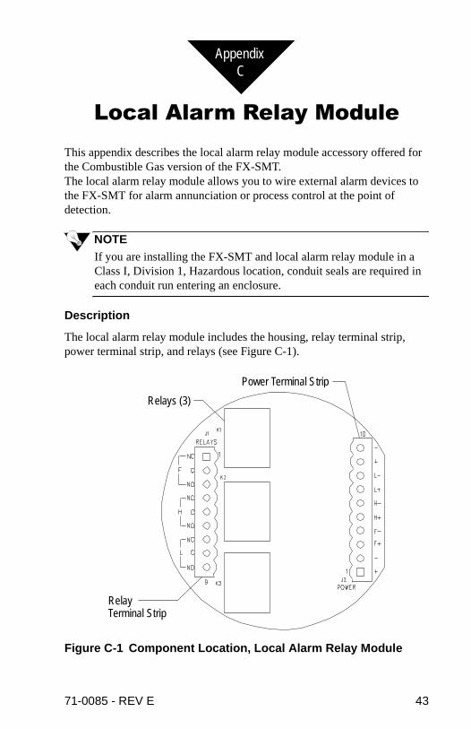
This appendix describes the local alarm relay module accessory offered for the Combustible Gas version of the FX-SMT.The local alarm relay module allows you to wire external alarm devices to the FX-SMT for alarm annunciation or process control at the point of detection.
NOTEIf you are installing the FX-SMT and local alarm relay module in a Class I, Division 1, Hazardous location, conduit seals are required in each conduit run entering an enclosure.
Description
The local alarm relay module includes the housing, relay terminal strip, power terminal strip, and relays (see Figure C-1).
Figure C-1 Component Location, Local Alarm Relay Module
Relay Terminal Strip
Relays (3)
Power Terminal Strip
71-0085 - REV E 43

FX-SMT Operator’s Manual
nals
5
HOUSING
The housing is explosion-proof, and it is suitable for installation in Class I, Division 1, Groups B, C, and D environments.The housing has three conduit hubs (3/4 in. NPT) for wiring connections to the relay and power terminal strips.
RELAY TERMINAL STRIP
The relay terminal strip has normally-closed (NC), common (C), and normally-open (NO) terminals for fail (F), high (H), and low (L) alarm conditions. The relay terminal strip facilitates connection to external alarm or process control devices.
POWER TERMINAL STRIP
The power terminal strip has separate positive (+) and negative (–) termifor low (L), high (H), and fail (F) alarm conditions. The power terminal stripfacilitates connection to the DC power source and the FX-SMT. The FX-SMT receives DC power from the local alarm relay module.
RELAYS
The relays are from top to bottom fail (K1), high (K2), and low (K3). Theapplicable relay activates when the FX-SMT is in a low, high, or fail condition. Each relay is normally-energized and de-energizes when activated.The relay contacts are isolated and are rated for 3 amps at 240 VAC andamps at 24 VDC and 115 VAC (resistive).
44 71-0085 - REV E

Appendix C
Installation
To mount the local alarm relay module and make wiring connections to the local alarm relay module, complete the following procedure.
MOUNTING THE LOCAL ALARM RELAY MODULE
1. Use the mounting lugs to mount the local alarm relay module to a vertical surface at the monitoring area.
Mount the local alarm relay module as close to the FX-SMT as possible.
WIRING THE LOCAL ALARM RELAY MODULE TO THE FX-SMT
CAUTIONObserve polarity when you make the wiring connections described in the following step.
2. Wire the power terminal strip (local alarm relay module) to the alarm output terminal strip (FX-SMT) as shown in the detailed table of Figure C-2.
3. Wire the external alarm device(s) to the local alarm relay module as described in the next section and shown in Figure C-3. Run the wiring through the conduit hub on the left side of the housing.
If you are using the FX-SMT with a receiver or controller, perform steps 4 and 5. If you are using the FX-SMT as a standalone device, go to step 5.
4. Wire the receiver or controller to the FX-SMT and local alarm relay module as shown in Figure C-2.
5. Wire the DC power source to the power terminal strip (local alarm relay module) as shown in Figure C-2.
71-0085 - REV E 45

FX-SMT Operator’s Manual
Figure C-2 Local Alarm Relay Module, General Wiring Diagram
46 71-0085 - REV E
Appendix C
er
-
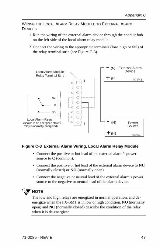
WIRING THE LOCAL ALARM RELAY MODULE TO EXTERNAL ALARM DEVICES
1. Run the wiring of the external alarm device through the conduit hub on the left side of the local alarm relay module.
2. Connect the wiring to the appropriate terminals (low, high or fail) of the relay terminal strip (see Figure C-3).
Figure C-3 External Alarm Wiring, Local Alarm Relay Module
• Connect the positive or hot lead of the external alarm’s power source to C (common).
• Connect the positive or hot lead of the external alarm device to NC (normally closed) or NO (normally open).
• Connect the negative or neutral lead of the external alarm’s powsource to the negative or neutral lead of the alarm device.
NOTEThe low and high relays are energized in normal operation, and deenergize when the FX-SMT is in low or high condition. NO (normally open) and NC (normally closed) describe the condition of the relay when it is de-energized.
External Alarm
+- (N)
(H)
Device
Power
+
- (N)
(H)
Local Alarm Relay(shown in de-energized state;
Source
Local Alarm Module Relay Terminal Strip
NC
NO
C
relay is normally energized)
DC (AC)
DC (AC)
1
9
71-0085 - REV E 47
FX-SMT Operator’s Manual
WIRING INCOMING POWER TO THE LOCAL ALARM RELAY MODULE
WARNINGMake connections at the local alarm relay module before you plug in or turn on the DC power. Before making any wiring adjustments, always verify that the DC power source is not live.
1. Run two DC power wires through the top conduit hub of the local alarm relay module.
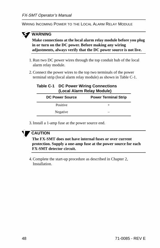
2. Connect the power wires to the top two terminals of the power terminal strip (local alarm relay module) as shown in Table C-1.
3. Install a 1-amp fuse at the power source end.
CAUTIONThe FX-SMT does not have internal fuses or over current protection. Supply a one-amp fuse at the power source for each FX-SMT detector circuit.
4. Complete the start-up procedure as described in Chapter 2, Installation.
Table C-1 DC Power Wiring Connections(Local Alarm Relay Module)
DC Power Source Power Terminal Strip
Positive +
Negative –
48 71-0085 - REV E