fx 3000 manual temp - hallmark refining 3000 manual.pdf · 4.4. manual operation ... 1.1 the...
TRANSCRIPT


HRC Hallmark RefiningCorporation®
STATEMENT OF WARRANTY AND LIABILITY
All equipment manufactured by Hallmark Refining Corporation is guaranteed against defects inmaterial and workmanship for a period of six months from the date of shipment from the factory. Anyclaimed defects must be reported, and the materials and/or equipment must be returned, freightprepaid, to HRC within the guarantee period. HRC's liability for defects in material and workmanshipshall be limited to replacing or repairing (at its option) such defective materials or equipment at no costto the original purchaser. Any damage or loss occurring during shipment is not covered by the terms ofthis warranty. Any shipping damage is the responsibility of the carrier(s) and should be reported to thecarrier(s) immediately.
All material and/or equipment furnished by other suppliers are not warranted by HRC and are coveredby the suppliers warranty only for defects in material and workmanship. Transportation, handlingdamage, normal wear and tear and other damage outside the control of HRC are not covered by thiswarranty. Under no circumstances will HRC be responsible for any of the following: damage, loss orliability of any nature arising out of the installation and/or use of the materials equipment and furnished.
There are no other warranties expressed or implied, except at stated above. This warranty becomesnull and void if any devices or accessories other than those distributed or officially recommended byHRC are installed, attached or used in conjunction with this equipment.

TABLE OF CONTENTS
1. THE ELECTROLYTIC SILVER PLATING PROCESS..............................................................1
2. SPECIFICATIONS .....................................................................................................................2
3. INSTALLATION..........................................................................................................................3
3.1. Unpacking ..........................................................................................................................3
3.2. Site Planning and Preparation ...........................................................................................3
3.3. System Placement .............................................................................................................3
3.4. Assembly............................................................................................................................3
3.4.1.Installation of Discharge Lines ...................................................................................3
3.4.2.Installation of Inlet Lines.............................................................................................3
3.4.3.Connection to the Power Supply ................................................................................3
3.4.4.Connection to the Silver Controller.............................................................................4
3.4.5.Wiring Connection of Pumps, Top Cells, “Pump Saver” ............................................4
3.4.6.Position of Pumps and Plumbing ...............................................................................4
3.4.7.Pump Saver................................................................................................................4
3.4.8.Drain Plugs and Anti-Aeration Plumbing (Tee Assembly) .........................................4
4. OPERATION ..............................................................................................................................5
4.1. Control Unit Display Functions...........................................................................................6
4.2. Auto Control .......................................................................................................................6
4.3. Calibration of "2 Step" Control ...........................................................................................7
4.4. Manual Operation...............................................................................................................7
5. TESTING....................................................................................................................................8
5.1. Silver Concentration Test Procedure .................................................................................8
5.2. Test Procedure...................................................................................................................8
6. MAINTENANCE.........................................................................................................................9
6.1. Harvesting the Silver ..........................................................................................................9
7. TROUBLESHOOTING.............................................................................................................10
8. REPLACEMENT PARTS LIST ................................................................................................11
9. ASSEMBLY DRAWINGS.........................................................................................................13
10. ELECTRO SILVER SENSOR (ANALYZER) ...........................................................................22
10.1 General Information.........................................................................................................22
11. SPECIFICATIONS....................................................................................................................23
11.1 Operational.......................................................................................................................23
11.2 Electrical ...........................................................................................................................23
11.3 Enclosures........................................................................................................................23
11.4 Net Weight........................................................................................................................23

12. PRINCIPLE OF OPERATIONS (ANALYZER) .........................................................................24
13. INSTALLATION (ANALYZER) .................................................................................................25
14. ELECTRICAL CONNECTIONS (ANALYZER) .........................................................................26
14.1 Sensor ..............................................................................................................................26
14.2 Analog Outputs..................................................................................................................26
14.3 Relay Outputs...................................................................................................................27
14.4. Line Power........................................................................................................................27
15. OPERATION (ANALYZER)......................................................................................................28
15.1 Controls and Indicators ...................................................................................................28
15.2 Preliminary Set-up ...........................................................................................................33
15.3 Setting Relay Functions...................................................................................................33
15.4 Setting the Range Expand ..............................................................................................35
16. CALIBRATION (ANALYZER) ...................................................................................................36
17. SYSTEM OPERATION AIDS (ANALYZER)............................................................................37
18. MAINTENANCE (ANALYZER)................................................................................................38
18.1 Sensor Cable..................................................................................................................38
18.2 Periodic System Check ..................................................................................................38
18.3 Relay Replacement ........................................................................................................38
19. TROUBLESHOOTING (ANALYZER)......................................................................................39
20. SILVER SENSOR (ORP) ASSEMBLY....................................................................................41
21. GENERAL INFORMATION (ORP)..........................................................................................42
19.1 Introduction.....................................................................................................................42
19.2 Cautions to be Observed................................................................................................42
22. SPECIFI-CATIONS (ORP) ......................................................................................................43
23. PRINCIPLE OF OPERATION (ORP) ......................................................................................44
24 MAINTENANCE (ORP) ...........................................................................................................45
24.1 Cleaning the Sensor .......................................................................................................45
24.2 Renewing the Salt Bridge...............................................................................................45
25. TROUBLESHOOTING (ORP) .................................................................................................46
26. REPAIR AND SPARE PARTS (ORP) .....................................................................................47
27. ELECTRICAL CONNECTIONS (ORP) ...................................................................................48
27.1 Direct Hook-up................................................................................................................48
27.2 Indirect Hook-up with Junction Box................................................................................48
27.3 Mounting.........................................................................................................................48
28. REPLACING ELECTRODES (ORP) .......................................................................................50
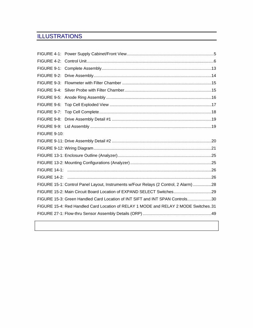
IILLLLUUSSTTRRAATTIIOONNSS
FIGURE 4-1: Power Supply Cabinet/Front View............................................................................5
FIGURE 4-2: Control Unit...............................................................................................................6
FIGURE 9-1: Complete Assembly................................................................................................13
FIGURE 9-2: Drive Assembly.......................................................................................................14
FIGURE 9-3: Flowmeter with Filter Chamber ..............................................................................15
FIGURE 9-4: Silver Probe with Filter Chamber............................................................................15
FIGURE 9-5: Anode Ring Assembly ............................................................................................16
FIGURE 9-6: Top Cell Exploded View .........................................................................................17
FIGURE 9-7: Top Cell Complete..................................................................................................18
FIGURE 9-8: Drive Assembly Detail #1 .......................................................................................19
FIGURE 9-9: Lid Assembly ..........................................................................................................19
FIGURE 9-10:
FIGURE 9-11: Drive Assembly Detail #2 .......................................................................................20
FIGURE 9-12: Wiring Diagram.......................................................................................................21
FIGURE 13-1: Enclosure Outline (Analyzer)..................................................................................25
FIGURE 13-2: Mounting Configurations (Analyzer) .......................................................................25
FIGURE 14-1: ..............................................................................................................................26
FIGURE 14-2: ..............................................................................................................................26
FIGURE 15-1: Control Panel Layout, Instruments w/Four Relays (2 Control, 2 Alarm) ................28
FIGURE 15-2: Main Circuit Board Location of EXPAND SELECT Switches.................................29
FIGURE 15-3: Green Handled Card Location of INT SIFT and INT SPAN Controls.....................30
FIGURE 15-4: Red Handled Card Location of RELAY 1 MODE and RELAY 2 MODE Switches.31
FIGURE 27-1: Flow-thru Sensor Assembly Details (ORP) ............................................................49

FX 3000 Silver Recovery System
1
11.. TTHHEE EELLEECCTTRROOLLYYTTIICC SSIILLVVEERR PPLLAATTIINNGG PPRROOCCEESSSS
1.1 The Electrolytic Silver Plating Process
This silver recovery method applies a direct current across two electrodes in a silver bearing solution.Metallic silver deposits on the cathode. Sulfite and thiosulfate are oxidized on the anode.
Care must be taken to control the current density in the cell because high density can cause “sulfiding.”Sulfiding is the decomposition of thiosulfate into sulfite at the cathode, which contaminates thedeposited silver and reduces recovery efficiency. The higher the silver concentration, the higher thecurrent density can be without sulfiding.
The HRC ELECTRO Series of silver recovery systems are designed to utilize the maximum amountplating surface in the cell. The cathode is a stainless steel cylinder in continuous motion, during theplating process. This creates a high level of agitation and maximizes the silver yield.
FX 3000 Silver Recovery System
2
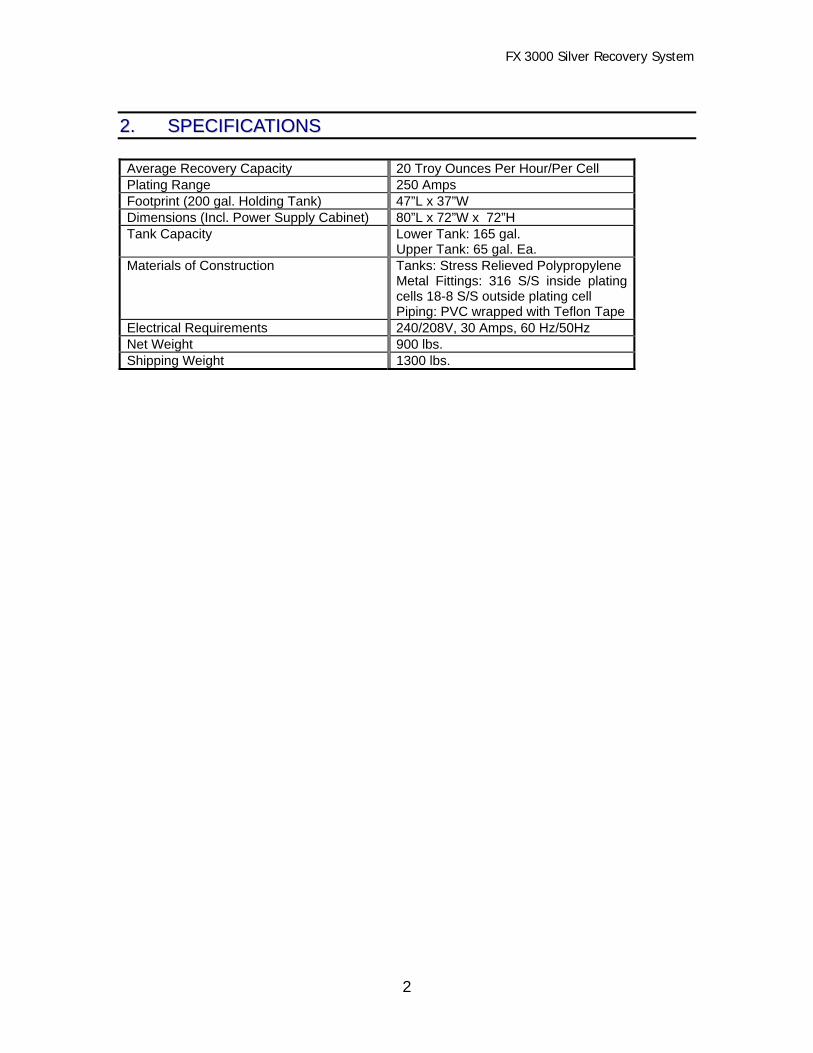
22.. SSPPEECCIIFFIICCAATTIIOONNSS
Average Recovery Capacity 20 Troy Ounces Per Hour/Per CellPlating Range 250 AmpsFootprint (200 gal. Holding Tank) 47”L x 37”WDimensions (Incl. Power Supply Cabinet) 80”L x 72”W x 72”HTank Capacity Lower Tank: 165 gal.
Upper Tank: 65 gal. Ea.Materials of Construction Tanks: Stress Relieved Polypropylene
Metal Fittings: 316 S/S inside platingcells 18-8 S/S outside plating cellPiping: PVC wrapped with Teflon Tape
Electrical Requirements 240/208V, 30 Amps, 60 Hz/50HzNet Weight 900 lbs.Shipping Weight 1300 lbs.

FX 3000 Silver Recovery System
3
33.. IINNSSTTAALLLLAATTIIOONN
The unit is shipped pre-plumbed, complete with all fittings and required tubing. The electricaloutlets and sockets are pre-wired at the factory, ready for fast and easy installation.
3.1 UnpackingRemove the unit from the shipping container. Remove all packing and protective materials.Examine all the components for any obvious shipping damage and report it immediately to thecarrier.
3.2 Site Planning and PreparationBefore you install the FX 6000 silver recovery equipment consider the location carefully. Therecovery equipment should be located so that the discharge lines from the process equipmentcan be easily connected to the lower tank of the recovery unit. Consider using PVC pipe insteadof tubing if the run is long. You must also consider the Mark 26 tailing system and transfer pumpstation and the proximity to a drain for discharge to the sewer after the recovery process iscompleted. Setting the equipment on the floor to see how it will layout before final installation is agood starting place.
3.3 System PlacementAfter you have determined the desired location, check the floor for level and adjust the FX 3000unit as necessary to a level operating position.
3.4 AssemblyRemove the top cell splash covers and check the cathode coupling bolts for secure operation.The cathode drive shafts must be installed in the drive couplings so the cathodes do not rub onthe anodes or tank bottom.
3.4.1 Installation of Discharge LinesInstall the discharge tubing on the silver probe mounting assembly located at the rear of thelower tank. The fitting is marked “out” and returns the desilvered solution to the processor.This return line must pass through a flow meter and valve prior to entry back into theprocessor. This flow meter and valve is not supplied with the unit. Install and secure hoseclamps on these fittings.
3.4.2 Installation of Inlet LinesConnect overflow lines from the processor(s) to the inlet of the FX 3000 lower tank. Connectthe overflow lines from the lower tank of the FX 3000 to a transfer station. This station isrequired, and is available as an added option to the system. The lines going to the FX 3000must be silver bearing waste only. (Fixers, Bleach/Fix and Stabilizers) It is the responsibilityof the installer to provide any flow control or anti-siphoning devices required for the operationof the unit.
3.4.3 Connection to the Power SupplyPosition the power supply in front of the FX 3000. Check the control panel to insure that allswitches are in the “off” position. Connect the power cord to the outlet box at the rear of the
FX 3000 Silver Recovery System
4
power supply with a 208/240VAC 50/60 Hz power source capable of delivering a minimum of30 amperes. Improper supply source voltages or grounds will void all warranties. Connectcathode and anode cable to the back of the power supply with the supplied bolts. Connectflexible conduit from the power supply to the FX 3000 top cell and match the numbered wiresto the same numbers on the terminal switch. NOTE Make “minus” cables and “plus”cables go to the corresponding location on the power supply.
3.4.4 Connection to the Silver ControllerMount the Silver Controller on a wall that is in close proximity to the FX 3000 unit. Check theController to insure that the power switch is in the “off” position. Connect to a 115VAC 50/60Hz power source. Connect the color coded multi pin plug from the power supply into theconnector from the silver controller. Connect the color coded multi pin connector from thesilver controller to the silver probe pre-amp (white box mounted at the rear of the FX 3000)Control wires need to be run in a separate shielded conduit.
3.4.5 Wiring Connection of Pumps, Top Cells, “Pump Saver”Connect flexible conduit between the top cells. Match the numbered wires to the numberedterminal strip. Connect flexible conduit to the lower pump outlet boxes. Connect the powercords from the pumps through the cord grips at the outlet boxes. Match the numbers using thewire nuts provided. Install end covers on the sides of the top cells and covers over the outletboxes.
3.4.6 Position of Pumps and PlumbingInstall Pump 1 and Pump 2 by matching color coded valves. NOTE Make sure valve “O”rings are in place. Connect tubing provided from pumps 1 and 2 to top cell valves. Connecttubing from Pump 3 to silver probe plumbing at the rear of the unit. Make sure all clamps aresecure.
3.4.7 Pump SaverHang the pump saver float switch assembly in the clamp provided between the top cells at the frontof the unit. Plug the connector into the receptacle which is mounted on the side of the right top cellsupport. NOTE Unit will not operate with float switch in the open or off position. Check levelof fix in the lower tank.
3.4.8 Drain Plugs and Anti-Aeration Plumbing (Tee Assembly)Install plugs provided on drain fittings positioned over lower tank. Install 3” anti aeration teeassembly to 3” fitting located at the bottom of each top cell.

FX 3000 Silver Recovery System
5
44.. OOPPEERRAATTIIOONN
Fuse
POWER SUPPLY
Power
2 3 4 1 2 31
Power SupplyDrives Pumps
CONTROL PANEL
CONTROL UNITCh 1 Ch 2 Probe
Max Min ProbeAdust
1
3
31
34
33
32
FIGURE 4-1: Power Supply Cabinet/Front View

FX 3000 Silver Recovery System
6
4.1 Control Unit Display FunctionsCurrent Channel 1 Displays Amps to left plating cell.Current Channel 2 Displays Amps to right plating cell.Probe/Output Switch Displays either Total Voltage or Voltage from Silver
ControllerMax. Control Adjusts High Current Control in Manual Operation -
Hi and Lo for final adjustment.Min. Control Adjusts Low Current Control in Manual Operation - Hi
and Lo for final adjustment.C-Probe Voltage limit Adjusts current in automatic operation - Hi and Lo for
final adjustment.Auto/Manual Switch Auto - Use C-Probe voltage limit to adjust amps.
Manual - Use Max/Min to adjust amps.Green Light Indicates Control Unit in operation.
CONTROL UNITCh 1 Ch 2 Probe
Max Min ProbeAdust
1
4.2 Auto Control
4.2.1 See setting relay functions, Section 15.3.
4.2.2 Switch on item #32, Figure 4-1 on the control panel to the Auto position. Pump 3, item 31,must always be left in “on” position. (If pump 3 must be turned off, the power switch on theSilver analyzer must be in the off position prior to pump 3 being shut off).
4.2.3 Switch on control unit to auto, item #1, Figure 4-1 and power switch on Power Supply.
4.2.4 Check that both upper plating cells and lower cell are filled with silver bearing solution
4.2.5 Pump saver switch must be in place in full lower tank and plugged in. Power supply andpumps will not operate without switch in this position.
4.2.6 Turn power switch on Silver Analyzer to “on” position.
4.2.7 Adjust the calibrate knob on the Silver Analyzer until 1.00 g/l is on display.
4.2.8 Set Probe adjust on Power Supply control to approx. 80 amps on each display.
FIGURE 4-2:Control Unit

FX 3000 Silver Recovery System
7
4.2.9 Adjust calibrate knob down to 0.55 (take note that the current will automatically comedown). The Set Current should be at approximately 20 amps per display.
4.2.10 Make final adjustments with Probe Adjust and Hi & Lo Limit.
4.2.11 Refer to Calibration, Section 16.
4.3 Calibration of “2 Step” Control
4.3.1 Repeat Auto Control instructions 4.2.1 through 4.2.6.
4.3.2 Put Auto/Manual switch to MANUAL on Power Supply control unit.
4.3.3 Adjust calibrate knob on the Silver Analyzer until ST.PT1 light comes on.
4.3.4 Adjust MIN control until 20 amps are on each digital display.
4.3.5 Adjust calibrate knob until ST.PT.2 light comes on.
4.3.6 Adjust MAX control until 40 amps are on each digital display.
4.3.7 Adjust Hi & Lo limit for final adjustment.
4.3.8 Refer to Calibration, Section 16.
4.4 Manual Operation 6.
4.4.1 All switches (item 32, figure 4-1) are to be in the manual position.
4.4.2 Pump 3 (Item 31, figure 4-1) must remain in the ON position.
4.4.3 Put Auto/Manual switch on the Power Supply control Unit in the Manual position. (Thepower supply pumps and cathode drive motors will operate without the control of the SilverAnalyzer or the Silver Probe).
4.4.4 Use the MIN knob for current adjust.
FX 3000 Silver Recovery System
8
55.. TTEESSTTIINNGG
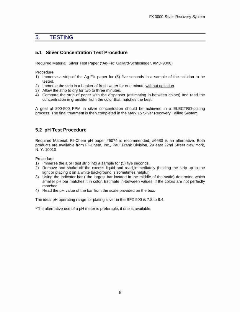
5.1 Silver Concentration Test Procedure
Required Material: Silver Test Paper (“Ag-Fix” Gallard-Schlesinger, #MD-9000)
Procedure:1) Immerse a strip of the Ag-Fix paper for (5) five seconds in a sample of the solution to be
tested.2) Immerse the strip in a beaker of fresh water for one minute without agitation.3) Allow the strip to dry for two to three minutes.4) Compare the strip of paper with the dispenser (estimating in-between colors) and read the
concentration in gram/liter from the color that matches the best.
A goal of 200-500 PPM in silver concentration should be achieved in a ELECTRO-platingprocess. The final treatment is then completed in the Mark 15 Silver Recovery Tailing System.
5.2 pH Test Procedure
Required Material: Fil-Chem pH paper #6074 is recommended; #6680 is an alternative. Bothproducts are available from Fil-Chem, Inc., Paul Frank Division, 29 east 22nd Street New York,N. Y. 10010
Procedure:1) Immerse the a pH test strip into a sample for (5) five seconds.2) Remove and shake off the excess liquid and read immediately (holding the strip up to the
light or placing it on a white background is sometimes helpful)3) Using the indicator bar ( the largest bar located in the middle of the scale) determine which
smaller pH bar matches it in color. Estimate in-between values, if the colors are not perfectlymatched.
4) Read the pH value of the bar from the scale provided on the box.
The ideal pH operating range for plating silver in the BFX 500 is 7.8 to 8.4.
*The alternative use of a pH meter is preferable, if one is available.

FX 3000 Silver Recovery System
9
66.. MMAAIINNTTEENNAANNCCEE
Do a routine daily visual inspection of the system and observe the following guidelines:
♦ Periodically inspect tubing and tighten clamp connections to avoid leaks. Check threadedPVC pipe connections and rewrap with teflon tape if necessary.
♦ Inspect drive assembly brushes and rubber couplers for wear. Replace if necessary. ♦ Inspect filters and pumps for proper flow. The flow meter should not fall below 8 Gals./Min.
If this happens, replace the filter and/or inspect the pumps for proper operation. ♦ Check calibration of silver controller and silver probe periodically. See Calibration, Section 16. ♦ Check silver sensor electrodes for wear of fouling. ♦ Inspect the drum (cathode) for proper plating and take corrective action if necessary. ♦ Inspect electrical connections at anode bar, drive assembly , power supply. Pay special
attention to large cable connections. ♦ Grease the bearings after harvesting the silver and cleaning the cathode. ♦ Keep extra parts on hand to avoid costly down time. It is recommended that you keep a
complete liquid end for each model of pump in service as well as rubber couplings, a drivemotor, drive motor bearings, brushes and drive shaft with slip ring.
♦ Keep your equipment clean and the work area around it free of clutter to avoid accidents
when working on or around the recovery unit.
6.1 Harvesting the Silver
1) After 25 to 30 lbs. of silver has been processed, the cathode drum should be removed fromthe recovery unit by loosening the bolt securing it to the drive head. Rinse excess chemicalwith fresh water.
2) The silver can than be removed from the drum using a putty knife or other scraping tool that
will minimize the scratching of the drum. 3) The plated silver should be scraped from the drum and allowed to dry. 4) Wash the drum with plain soap and water before returning the it to the recovery unit. 5) Place the drum back in the drive and tighten bolt securing it to the drive head. 6) The dry silver can than be packaged and shipped to Hallmark for refining.
Note: Silver can be shipped as a non-hazardous material in all states except California. Silver is ahazardous material in California and it must be labeled and manifested for shipment.

FX 3000 Silver Recovery System
10
77.. TTRROOUUBBLLEESSHHOOOOTTIINNGG
PROBLEM PROBABLE SOLUTION
Cathode will not plate. • Cathode coupling may be loose or dirtyconnection.
• Brush may be sticking in holder, clean andlubricate
• Power supply malfunction, check circuitbreaker. Replace power supply if necessary.
Plating on cathode is soft. • Too much power is being applied. Reducethe amperage, fixer low on sulfite.
Plating on cathode not smooth(nodules on plating surface).
• Not enough power is being applied. Increaseamperage.
Solution empties from the tankduring the plating time.
• On lower tank, check for leaks or breaks inthe plumbing. Check filter and lines back toprocessor.
• On Upper tank, check for leaks or breaks.Make sure check valves are working.
• Solution may be siphoning out through thepump out tube. The tube should be raised tolevel higher than the plating tank.
Drive motor not turning. • A voltage spike may have blown the fuse.Check fuse in drive head.
Pump not transferring solution. • Check switch and circuit breaker. Liquid endmay be clogged.
• Check pump motor for operation.• Lower tank switch may have shut down unit
due to no solution returning from the filmprocessors
System cycles on and off pastthe silver sensor set points foron and off
• Re-calibrate probe and solution• Signal wires to probe need to be shielded
and properly grounded Cathode not turning • Rubber coupling defective
• Circuit breaker open• Check manual auto switch.

FX 3000 Silver Recovery System
11
88.. RREEPPLLAACCEEMMEENNTT PPAARRTTSS LLIISSTT
Ref No Part Number Part Description QuantityFig. 1 Power Supply 1
1 Dual 125 Controller 12 Drive Assembly Mounting Bolts 323 Dual 125 Amp Power Supply 14 Cathode Coupler Set Screw 316 S/S 85 Cathode Coupler Bolt 3/8”x1/2” 316 SS 86 107-010 Tubing Reinforced 1" 127 18645A23 Lid Handles 316 SS 68 250-001 Power Supply Door Hinge SS 29 250-006 Drive Assembly Hinge 6”x3” SS 410 251-002 Drive Assembly Rubber Feet 811 253-010 Plastic Pipe Bracket 1” Clic 512 4276 Transformer 113 504-010 Valve Globe Asahi 1” 214 506-010 Valve Duo Bloc Asahi 1" 815 507-010 Valve Plastomatic 316 522-010 Hose Clamps #10 SS 617 524-001 Liquid Level Switch/Compac (Inside tank) 118 540-006 Filter Chamber Bracket 1” 219 540-210 Filter Chamber 320 540-213 Filter 321 541-011 Flowmeter (0-40 GPM) 222 543-043 Flexible Reducer 4”x3” (Inside tank) 223 600-001 Outlet Box 224 601-005 Cord Grip ½” 625 710-016 Power Cord 16x3 Chemically Resistant 626 710-020 2/0 Cable 3227 710-250 Cable 250MCM 1228 711-020 2/0 Lug 829 711-300 300 Lug 430 713B4A1001 Silver Sensor Probe (Detail Fig. 27.3) 131 726-001 Switch On-Off 132 726-002 Switch On-Off-On 1733 741-003 Circuit Breaker 3 Amp 634 741-007 Circuit Breaker 7 Amp 135 742-001 Polytuff Flexible Conduit ¾” 1636 742-002 Straight Liquid Tite Connector 1137 742-003 Elbow Liquid Tite 338 744-003 Terminal Strip 4439 744-117 Panel Mount 16 Pin Socket Connector 240 77005 Anode Mounting Bolts 316SS 7641 78013 Anode Mounting Washers 316SS 7642 900-002 Anode Clip 243 900-004 Anode Ring 244 900-007 Anode Support 3245 900-008 Electro Lock/Drive Support 4
FX 3000 Silver Recovery System
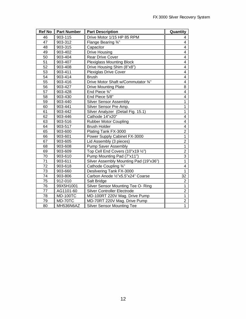
12
Ref No Part Number Part Description Quantity46 903-115 Drive Motor 1/15 HP 85 RPM 447 903-312 Flange Bearing ¾” 448 903-315 Capacitor 449 903-402 Drive Housing 450 903-404 Rear Drive Cover 451 903-407 Plexiglass Mounting Block 452 903-408 Drive Housing Shim (8”x8”) 453 903-411 Plexiglas Drive Cover 454 903-414 Brush 455 903-416 Drive Motor Shaft w/Commutator ¾” 456 903-427 Drive Mounting Plate 857 903-428 End Piece ¾” 458 903-430 End Piece 5/8" 459 903-440 Silver Sensor Assembly 160 903-441 Silver Sensor Pre Amp. 161 903-442 Silver Analyzer (Detail Fig. 15.1) 162 903-446 Cathode 14”x20” 463 903-516 Rubber Motor Coupling 464 903-517 Brush Holder 465 903-600 Plating Tank FX-3000 266 903-601 Power Supply Cabinet FX-3000 167 903-605 Lid Assembly (3 pieces) 268 903-608 Pump Saver Assembly 169 903-609 Top Cell End Covers (10”x19 ½”) 270 903-610 Pump Mounting Pad (7”x11”) 371 903-611 Silver Assembly Mounting Pad (19”x36”) 172 903-618 Cathode Coupling ¾” 473 903-660 Desilvering Tank FX-3000 174 903-806 Carbon Anode ½”x5.5”x24” Coarse 3275 912-010 Salt Bridge 276 99X5H1001 Silver Sensor Mounting Tee O- Ring 177 AG1101-60 Silver Controller Electrode 278 MD-100TC MD-100RT 220V Mag. Drive Pump 179 MD-70TC MD-70RT 220V Mag. Drive Pump 280 MH536N6AZ Silver Sensor Mounting Tee 1

FX 3000 Silver Recovery System
13
99.. AASSSSEEMMBBLLYY DDRRAAWWIINNGGSS
FIGURE 9-1: Complete Assembly
Larger Drive Pumpon other side
46
21
18
2060
1930
80
1116
6
70
59
14
7173
65 65
5050
49
20
13
25
23
24
(4) Bolts each DriveAssembly
19
15
1478
79
2
1930

FX 3000 Silver Recovery System
14
FIGURE 9-2: Drive Assembly
58
57
6455
54
72
62
46
9
56
50

FX 3000 Silver Recovery System
15
FIGURE 9-3: Flowmeter with Filter Chamber
FIGURE 9-4: Silver Probe with Filter Chamber
19
21
14
13
18
30
1980
14
20
11
59
20

FX 3000 Silver Recovery System
16
FIGURE 9-5: Anode Ring Assembly
74
43
44
4241
40

FX 3000 Silver Recovery System
17
FIGURE 9-6: Top Cell Exploded View
13
19
21
43
42
46
45
62
10
74
20
FX 3000 Silver Recovery System
18
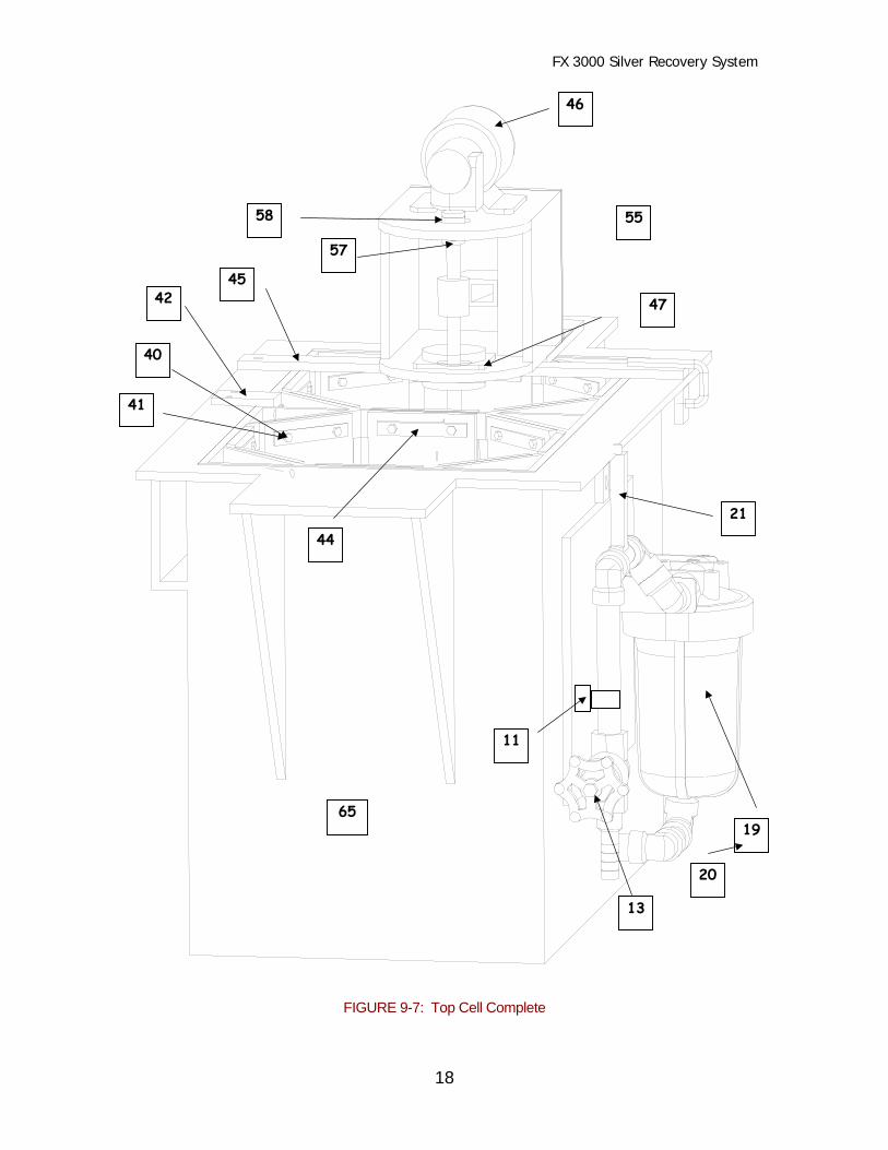
FIGURE 9-7: Top Cell Complete
41
21
44
13
19
42
40
47
55
46
58
57
45
11
65
20

FX 3000 Silver Recovery System
19
FIGURE 9-8: Drive Assembly Detail #1
FIGURE 9-9: Lid Assembly
46
58
57
6454
55
53
4
572
7
47

FX 3000 Silver Recovery System
20
FIGURE 9-11: Drive Assembly Detail #2
51
4849
46
53
64
2
56
9
4
72
5

FX 3000 Silver Recovery System
21
FIGURE 9-12: Wiring Diagram
24V
208V
24V
120V
24V
115V
208V
StepDown
Transformer
SILVERCONTROLLER
POWER SUPPLYCONTROLLER
POWERSUPPLY
AutoOffMan
Pumps&
Drives
AutoOffMan
PowerSupply
Hot
Whit
eGr
een
208V
Blac
kVi
olet
Yello
wGr
eyDk
. Bro
wnBl
ue Red
Blac
kVi
olet
Lt. B
rown
Lt. B
rown
Red
Gree
n
Red
Red
Blue
Yello
w
Blac
kW
hite
Lt. B
rown
Yello
w
Oran
geW
hite
Gree
n
To Terminal Strip on Top Cell
D1 D2 D3 D4 P1 P2 P3 PumpSaver Ground
1 2 3 4 5 7 8 9 151413121110 1817166
Fuses

Electro Silver Sensor
22
1100.. EELLEECCTTRROO SSIILLVVEERR SSEENNSSOORR ((AANNAALLYYZZEERR))
10.1 GENERAL INFORMATION
♦ This manual includes information on installing, operating, maintaining and troubleshooting theModel 90H Specific Ion Analyzer. Identification of controls, switches and indicators is bold-faced for easy reference.
♦ The Model 90H is a compact electronic instrument which provides power for the associated
sensor, receives signals from sensor and processes those signals which may be used forindication, transmission and control functions.
♦ The Model 90H can be equipped with a variety of options. This manual describes all analog
output and relay options. Only options supplied with this instrument will apply. ♦ The instrument requires line power as specified on the label affixed to the enclosure.
Whenever line power is discussed in this manual, assume it to be that which is specified.

Electro Silver Sensor
23
1111.. SSPPEECCIIFFIICCAATTIIOONNSS
11.1 OPERATIONALSensitivity………………………………… 0.1% of spanStability…………………………………… 0.2% span per 24 hrs., non-cumulativeNon-Linearity…………………………….. 0.1% of spanDisplay……………………………………. 4 ½” mirrored scaleResponse Time………………………….. 0.1 and 1.0 seconds, selectableAmbient Conditions…………………….. -30º to 50ºC (-22º to 122ºF), 0-100% R.H.Control/Alarm Setpoints……………….. 0-100% of full scale, adjustable with press-to-
display setpoint featureControl Deadband………………………. 0-50% of full scale, adjustableIndicators………………………………… LED lights when relay turns on*Contact Rating (U.L.)………………….. SPDT, 5A 115/230 VAC, 30A @ 30 VDC
resistiveTemperature Compensation…………… Automatic, 0-95ºC (32º-203ºF)Sensor-to-Analyzer Distance………….. 3000 feet maximum
*NOTE:Control or alarm relays operate on increasing or decreasing reading, switch selectable.
11.2 ELECTRICALPower…………………………………….. 98-132 VAC, 50 or 60 Hz.Analog Outputs………………………….. One voltage and one current signal (non-
isolated):0-1 mA, 100 ohms maximum load0-5 VDC, 50K ohms minimum load
11.3ENCLOSURE………………………
NEMA 4X, styrene structural foam (with flameretardant additive), panel/surface/pipe mount
11.4 NET WEIGHT12 lbs. (5.5 kg) maximum

Electro Silver Sensor
24
1122.. PPRRIINNCCIIPPAALL OOFF OOPPEERRAATTIIOONN
12.1 The analyzer is a special type of differential voltmeter with analog output. The instrumentuses solid-state integrated circuits which operate on low voltages. The gains and offsetsof most circuits are set by 1% precision resistors. This and the use of high gain integratedcircuits provide stability and eliminate changes due to component aging.
12.2 The power supply uses a transformer to step down the line voltage. The stepped-downvoltage is full-wave rectified by a diode bridge. Ripple voltages are removed in acapacitor input filter which provides a DC voltage for integrated circuit regulators. Fourvoltages are produced: (+) and (-) 15 VDC and (+) and (-) 18 VDC.
12.3 The scaling section of the analyzer consists of three stages. The first stage subtracts thetwo signals from the sensor, yielding a differential measurement. The second stagefeeds this differential signal through a resistor network which includes a temperaturesensitive resistor in the sensor to accomplish the required temperature compensation.The third stage amplifies this signal to scale it to 0-5 VCK over the range of interest.This 0-5 VDC signal is used for the analog output(s), display indication and as an inputto analyzer options.
12.4 The current output/range expand section amplifies the 0-5 VDC signal and shifts it toexpand the range. This signal is fed to a current output stage which changes the signalvoltage to a current output. The output stage is a true current injector (load resistor isnot required in current output circuit).
12.5 The isolated current output section, if provided, uses the 0-5 VDC signal produced by thescaling section. The input side of the isolator compares the 0-5 VDC signal to a trianglewave and generates a pulse train of variable duty cycle applied to a light emitting diode(LED) in an optical isolator. The optical isolator has a photo transistor which interceptsthe LED’s optical output and generates a pulsed output of variable duty cycle. This pulsetrain is filtered and scaled to produce a 0-5 VDC signal over the full range. This signal isused for display and as an input to other options. The input and output are isolated to1000 VDC.
12.6 The relay control section, if provided, operates by comparing the 0-5 VDC signal to avariable setpoint signal. When the signal is greater than the setpoint signal, the output ofa high gain amplifier changes voltage levels to turn on the relay. Part of the amplifieroutput is fed back to the amplifier input to establish a degree of hysteresis (deadband).The deadband range may be varied from 0-50% of full scale by adjusting the amount offeedback. When a relay turns on, an LED lights next to the relay’s setpoint control. Thisaids in setting the control.

Electro Silver Sensor
25
1133.. IINNSSTTAALLLLAATTIIOONN
13.1 Mount in as clean and dry a location as possible where minimal mechanical vibrationexists. Avoid locations where corrosive fluids may fall on the instrument or its ambienttemperature limits may be exceeded.
13.2 Refer to Figure 13-1 for enclosure and mounting dimension details. Figure 13-2 illustratesvarious mounting configurations. Use the two stainless steel brackets provided to panel,surface or pipe-mount the instrument. The bracket attachment configuration determinesthe mounting method.
13.3 Conduit hubs or cable feed-thru fittings should be used where cables enter theenclosure. Holes not used for cable entry should be sealed with plugs.
FIGURE 13-1 Enclosure Outline
FIGURE 13-2 Mounting Configurations

Electro Silver Sensor
26
1144.. EELLEECCTTRRIICCAALL CCOONNNNEECCTTIIOONNSS
Electrical connections are made to terminal strips within the instrument enclosure. They areaccessed by loosening two thumbscrews and swinging open the inner control panel. Refer toappropriate electrical hook-up diagram for connection details.
14.1 SENSORConnect sensor (or interconnect) cable lead wires to Terminals 15 through 20 on TB2,matching colors as indicated.
It is recommended that sensor and interconnect cable be run in ½” metal conduit for protectionagainst moisture and mechanical damage. Do no run power or control wiring in the same conduit(“electrical noise” may interfere with sensor signal).
ANALOG OUTPUTS
FIGURE 14-1Electrical Hook-up Diagram Instruments With No
FIGURE 14-2Electrical Hook-up Diagram
Electro Silver Sensor
27
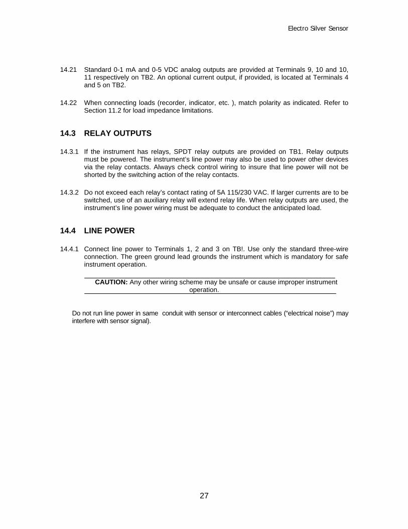
14.21 Standard 0-1 mA and 0-5 VDC analog outputs are provided at Terminals 9, 10 and 10,11 respectively on TB2. An optional current output, if provided, is located at Terminals 4and 5 on TB2.
14.22 When connecting loads (recorder, indicator, etc. ), match polarity as indicated. Refer toSection 11.2 for load impedance limitations.
14.3 RELAY OUTPUTS
14.3.1 If the instrument has relays, SPDT relay outputs are provided on TB1. Relay outputsmust be powered. The instrument’s line power may also be used to power other devicesvia the relay contacts. Always check control wiring to insure that line power will not beshorted by the switching action of the relay contacts.
14.3.2 Do not exceed each relay’s contact rating of 5A 115/230 VAC. If larger currents are to beswitched, use of an auxiliary relay will extend relay life. When relay outputs are used, theinstrument’s line power wiring must be adequate to conduct the anticipated load.
14.4 LINE POWER
14.4.1 Connect line power to Terminals 1, 2 and 3 on TB!. Use only the standard three-wireconnection. The green ground lead grounds the instrument which is mandatory for safeinstrument operation.
CAUTION: Any other wiring scheme may be unsafe or cause improper instrumentoperation.
Do not run line power in same conduit with sensor or interconnect cables (“electrical noise”) mayinterfere with sensor signal).

Electro Silver Sensor
28
1155.. OOPPEERRAATTIIOONN
15.1 CONTROLS AND INDICATORS
The frequently used controls are located on the control panel and are accessed by opening theenclosure door. The seldom used controls are located on the main circuit board or on specificplug-in circuit cards as noted in the following descriptions.
The following items are provided on all instruments.
15.1.1 ON/OFF power switch (on front panel see Figure 15-1)
ON - Connects line power to instrument circuits through ½ amp. in-line fuse.OFF - Removes line power from instrument circuits.
FIGURE 15-1Control Panel Layout, Instruments With Four Relays (Two Control, Two Alarm)

Electro Silver Sensor
29
15.1.2 PWR ON indicator (green, on front panel, see Figure 15-1)
Lights whenever instrument is powered and in-line fuse is intact.
15.1.3 RUN/TEST switch (on front panel, see Figure 15-1)
RUN - Connects sensor signal to analyzer circuits to measure value.TEST - Connects simulated sensor signal to analyzer circuits for test or diagnosticpurposes. In this position, specific ion values can be simulated with CALIBRATE controlto manually set display reading and analog outputs to desired value without disruptinginstrument calibration. Control setpoints, alarm points and range expand are establishedusing this switch position.
15.1.4 CALIBRATE control (on front panel, see Figure 15-1)
Continuously variable control has two functions depending on position of RUN/TESTswitch:
A. In RUN, it shifts display reading to proper value for calibration with sensor in solutionof known value.
B. In TEST, it shifts display reading and analog outputs for test or diagnostic purposes.This includes setting control setpoints, alarm points and range expand.
Control’s 0-100 adjustment range represents 0-100% of full scale.
15.1.5 SPAN control (on front panel, factory-set and locked, see Figure 15-1)
Continuously variable control adjusts span (gain) of instrument during factory calibrationwith RUN/TEST switch in RUN position only. This control shifts display reading slightlyand its adjustment range is arbitrary.
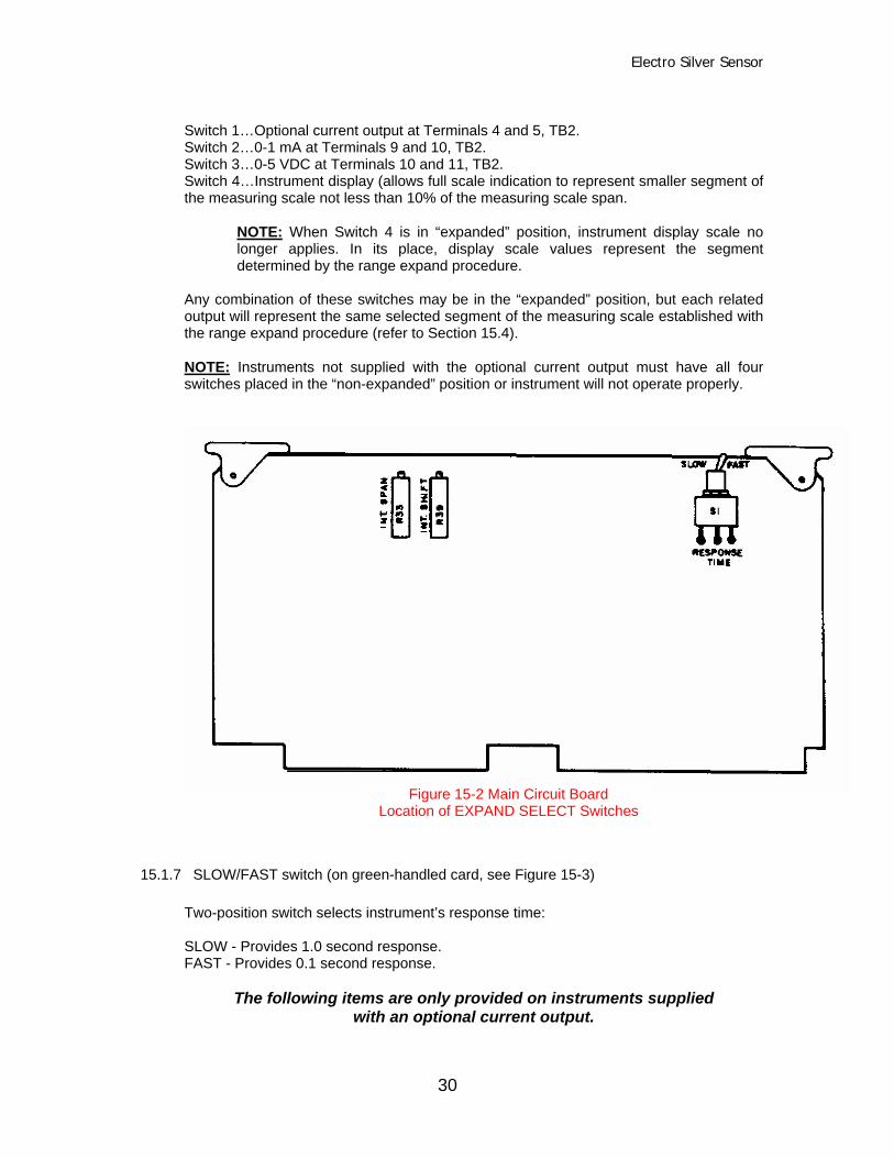
15.1.6 EXPAND SELECT switches (on main circuit board, see Figure 15-2)
This block of four individual slide switches select specific analog outputs to represent thefull measuring scale (“non-expanded” position) or a selected segment of the measuring
scale span (“expanded” position). Each switch represents a specific analog output:
Electro Silver Sensor
30
Switch 1…Optional current output at Terminals 4 and 5, TB2.Switch 2…0-1 mA at Terminals 9 and 10, TB2.Switch 3…0-5 VDC at Terminals 10 and 11, TB2.Switch 4…Instrument display (allows full scale indication to represent smaller segment ofthe measuring scale not less than 10% of the measuring scale span.
NOTE: When Switch 4 is in “expanded” position, instrument display scale nolonger applies. In its place, display scale values represent the segmentdetermined by the range expand procedure.
Any combination of these switches may be in the “expanded” position, but each relatedoutput will represent the same selected segment of the measuring scale established withthe range expand procedure (refer to Section 15.4).
NOTE: Instruments not supplied with the optional current output must have all fourswitches placed in the “non-expanded” position or instrument will not operate properly.
15.1.7 SLOW/FAST switch (on green-handled card, see Figure 15-3)
Two-position switch selects instrument’s response time:
SLOW - Provides 1.0 second response.FAST - Provides 0.1 second response.
The following items are only provided on instruments suppliedwith an optional current output.
Figure 15-2 Main Circuit BoardLocation of EXPAND SELECT Switches

Electro Silver Sensor
31
15.1.8 INT. SHIFT control (R39 on green-handled card, see Figure 15-3)Continuously variable control adjusts display reading to its minimum-scale value duringrange expand procedure to establish the low limit of a selected segment of the measuringscale (see Section 15.4). The minimum value of each analog output selected withEXPAND SELECT switches (item 6) is provided when the specific ion value is at orbelow segment’s low limit. Control’s adjustment range is 0 to 100% of full scale.
15.1.9 INT. SPAN control (R33 on green-handled card, see Figure 15-3)
Continuously variable control adjusts display reading to its maximum-scale value duringrange expand procedure to establish the high limit of a selected segment of themeasuring scale (see Section 6.4). The maximum value of each analog output selectedwith EXPAND SELECT switches (item 6) is provided when the specific ion value is at orabove segment’s high limit. Control’s adjustment range is 0 to 10% of full scale.
The following items are only provided on instrumentssupplied with a relay option.
15.1.10 RELAY 1 (2) MODE switches (on red-handled card, see Figure 15-4)
HI - Selects “high phase” operation for respective relay; turns on in response toincreasing specific ion value.LO - Selects “low phase” operation for respective relay; turns on in response todecreasing specific ion value.
NOTE: If instrument is supplied with four relays, these switches apply to control relaysonly.
FIGURE 15-4 Red Handled CardLocation of RELAY 1 MODE and RELAY 2 MODE Switches

Electro Silver Sensor
32
15.1.11 ST.PT.1 (2) controls (on front panel, see Figure 15-1)
Each continuously variable control sets the point at which its respective control relay (1,2) turns on in response to increasing specific ion value. Relay remains on wheneverspecific ion value is above this selected setpoint value. Control’s 0-100 adjustment rangerepresents 0 to 100% fo the full scale.
NOTE: Underlines indicate “high phase” relay operation. Opposite relay operation occurswhen a “low phase” is selected with RELAY MODE switch (see item 19).
15.1.12 ST.PT.1 (2) indicator (yellow, on front panel, see Figure 15-1)Each indicator lights whenever their respective controls relay (1, 2) turns on.
15.1.13 ST.PT.1 (2) CHK push-button switches (on front panel, see Figure 15-1)Each switch, when pressed, displays its respective control relay’s setpoint value set bythe ST.PT.1 and ST.PT.2 controls. When released, momentary action type switch returnsto its “off” position and display resumes its “regular” indication mode.
15.1.14 D.B.1 (2) controls (on front panel, see Figure 15-1)
Each continuously variable control sets the point at which its respective control relay (1,2) turns off when the specific ion value decreases below the preselected setpoint valueset by the ST.PT.1 and ST.PT.2 controls. This establishes a range or “deadband” inwhich the control relay remains on. Control’s 0-100 adjustment range representsapproximately 0 to 50% of full scale.
NOTE: Underlines indicate “high phase” relay operation. Opposite relay operation occurswhen a “low phase” is selected with RELAY MODE switch (see item 10).
15.1.15 ALM.PT.1 (2) controls (on front panel, see Figure 15-1)
Each continuously variable control sets the point at which its respective alarm relay turnson (in response to decreasing specific ion value for alarm relay #1 and increasingspecific ion value for alarm relay #2). Whenever specific ion value is below ALM.PT.1 orabove ALM.PT.2, the respective relay remains on. Control’s 0-100 adjustment rangerepresents 0 to 100% of full scale.
15.1.16 ALM.PT.1 (2) indicators (red, on front panel, see Figure 15-1)
Each indicator lights whenever its respective alarm relay (1, 2) turns on.
15.1.17 ALM.PT.1 (2) CHK push-button switches (on front panel, see Figure 15-1)
Each switch, when pressed, displays its respective alarm relay’s alarm point value set bythe ALM.PT.1 and ALM.PT.2 controls. When released, momentary action type switchreturns to its “off” position and display resumes its “regular” indication mode.

Electro Silver Sensor
33
The following control is only provided on instrumentswith a meter display.
15.1.18 METER ZERO control (located on meter face)
Adjusts meter movement mechanically to align meter pointer to minimum-scale valuewith line power removed from the instrument.
15.2 PRELIMINARY SET-UP
15.2.1 Before operating instrument for the first time, place power ON/OFF switch to OFF andthe following controls and switches to these settings:
NOTE: Depending on options supplied with his instrument, specific controls may notapply.
Control Setting
CALIBRATE control………………… Mid-rangeSPAN control……………………….. Mid-rangeRUN/TEST switch………………….. TESTINT. SHIFT control…………………. Fully counterclockwise (left)INT. SPAN control………………….. Fully counterclockwise (left)EXPAND SELECT switches………. “Non-expanded” (see Figure 6-2)
- Instrument with Relay Option -
RELAY 1 (2) MODE switches…….. HI or LO (see Table A, item 10)ST.PT.1 (2) controls……………….. Fully counterclockwise (left)D.B.1 (2) controls…………………… Fully counterclockwise (left)ALM.PT.1 control…………………… Fully counterclockwise (left)ALM.PT.2 control…………………… Fully clockwise (right)
15.2.2 For instruments with meter displays, adjust METER ZERO control to make meterexactly indicate its minimum-scale value.
15.2.3 Apply line power and allow instrument to stabilize for at least 10 minutes beforecalibrating. While waiting, control setpoints, deadbands and alarm points may be set.
15.3 SETTING RELAY FUNCTIONS
With RUN/TEST switch in TEST, use CALIBRATE control to make display indicatedesired specific ion value when establishing relay operation.
NOTE: If instrument is calibrated, note value on display when placing RUN/TEST switchto TEST. After establishing relay functions, use CALIBRATE control to restore notedreading so calibration will be maintained when RUN/TEST. Switch is returned to RUN.

Electro Silver Sensor
34
15.3.1 Place RUN/TEST switch to TEST.
15.3.2 To set control relay 1’s setpoint, adjust CALIBRATE control until display indicates 0.70g/l. Turn ST.PT.1 control slowly until ST.PT.1 indicator lights (relay turns on).
15.3.3 To set control relay 1’s deadband, turn D.B.1 control fully clockwise (right). AdjustCALIBRATE control until display indicates 0.50 g/l. Turn D.B.1 control slowlycounterclockwise (left) until ST.PT.1 indicator turns off (relay turns off).
15.3.4 To set control relay 2’s set point, adjust CALIBRATE control until display indicates 1.00g/l. Turn ALM.PT.1 control slowly until ST.PT.2 indicator lights (relay turns on).
15.3.5 To set CONTROL Relay 2’s deadband, turn D.B.2 control fully clockwise. AdjustCALIBRATE control until display indicates 0.70 G/L. Turn D.B.W control slowlycounterclockwise until ST.PT.2 indicator turns off (Relay turns off).
15.3.7 Use CALIBRATE control to shift display reading back and forth, through the established setpoint and deadband, to verify that relays turn on and off at these points. If further
adjustment is required, repeat the steps previously described.
After relay functions are set, relay setpoint and alarm point values may be displayed and verifiedany time by pressing the appropriate ST.PT.CHK push-buttons.
15.3.6 Changing Relay SetpointA. Press relay’s ST.PT.CHK push-button and simultaneously adjust its ST.PT. control
to make display indicate new setpoint value. The new setpoint is now set anddisplayed for verification.
NOTE: a 0.5% of full scale difference can exist between the press-to-display value andthe actual setpoint value the relay turns on at. If this is critical, always use the proceduredescribed in steps 15.3.1 through 15.3.7 for setting the setpoint.
B. Release ST.PT.CHK push-button.
The alternate method for changing a relay setpoint is to use steps 15.3.1 through 15.3.7.
NOTE: Changing the setpoint does not affect the deadband setting. The deadband rangewill remain as a percent of full scale units from the setpoint.
15.4 SETTING THE RANGE EXPAND
INT. SHIFT and INT. SPAN controls are used to establish a segment of the measuringscale that will represent the analog outputs selected with the EXPAND SELECT switches(see Table A, item 6).
NOTE: Selected segment cannot be smaller that 10% of the measuring scale span, butmay be positioned anywhere within that span.
The procedure to apply the range expand feature is described using the following

Electro Silver Sensor
35
example. Suppose measuring scale is 0.10-5.00 g/l (4.90 g/l span). The smallestsegment that may be expanded is 0.49 g/l (10% of measuring scale span). The 4-20 mAanalog output is desired within a selected segment between 0.20 and 2.50 g/l.
15.4.1 Place RUN/TEST switch to TEST. Note display reading.
15.4.2 Adjust CALIBRATE control until display indicates the value at which 4 mA is to beprovided (0.20 g/l for this example).
15.4.3 Place EXPAND SELECT switch 4 to “expanded”. Adjust INT. SHIFT control until displayindicates its minimum-scale value (0.10 g/l for this example).
15.4.4 Place EXPAND SELECT Switch 4 to “non-expanded”. Adjust CALIBRATE control untildisplay indicates the value at which 20 mA is to be provided (2.50 g/l for this example).
15.4.5 Place EXPAND SELECT Switch 4 to “expanded”. Adjust INT.SPAN control until displayindicates its full-scale value (5.00 g/l for this example).
15.4.6 To obtain greater accuracy, repeat steps 15.4.2 through 15.4.5 until the segment’s limitscorrespond with minimum-scale and full-scale values.
15.4.7 Place EXPAND SELECT Switch 1 to “expanded”. The 4-20 mA analog output is nowprovided within the desired segment (0.20 to 2.50 g/l for this example).
NOTE: Each analog output selected with EXPAND SELECT switches represents thesame segment established using this procedure. When EXPAND SELECT Switch 4 is in“expanded” position, instrument’s measuring scale represents values established withrange expand procedure.
15.4.8 Adjust CALIBRATE control until display indicates the value noted in step 15.4.1 PlaceRUN/TEST switch to RUN. This maintains calibration if instrument was calibrated priorto setting the range expand.

Electro Silver Sensor
36
1166.. CCAALLIIBBRRAATTIIOONN
16.1 This instrument's measuring accuracy is a function of the calibration procedure. Thisprocedure requires a clean sensor and a sample of solution whick has the same specific ionvalue as the sensor Is standard cell solution.
16.2 Place RUN/TEST switch to RUN.
Place clean sensor, with protective cap removed, in the sample of solution. Allow sensor toattain temperature equilibrium with the solution (display reading stabilizes). Adjust CALIBRATEcontrol until display indicates the known value of the solution
The instrument is now calibrated. The SPAN control has been preset and locked at the factory.No adjustment of this control is required.
The RUN/TEST switch allows the CALIBRATE control to be changed without disrupting systemcalibration. Anytime the CALIBRATE control is used for relay function or range expand set-up,place RUN/TEST switch to TEST, note display reading and set these functions as required.Then, using the CALIBRATE control, return display reading back to noted value and placeRUN/TEST switch back to RUN.
Electro Silver Sensor
37
1177.. SSYYSSTTEEMM OOPPEERRAATTIIOONN AAIIDDSS
17.1 The sensor is shipped and should be stored with its protective plastic cap over theelectrode end. Remove cap just before use. Store this cap for future use. If sensor is tobe out of solution for more than a day or two, put a few drops of water into protective capand replace it oil sensor. This keeps the salt bridge from drying out which avoids slowresponse when sensor is put back into service.
NOTE: Protective cap must be removed when sensor is put into service or it will not operate.
The sensor’s electrodes must be clean for accurate readings.
17.2 This instrument may be affected by electrical disturbances referred to as It ground 'loops".around loops may occur when an analog signal) is connected to an external device witha grounded input. Relay control normally will not cause ground loops. To check, for aground loop which may cause erroneous readings, disconnect analog signal leads andobserve if display changes to a different reading. A new reading indicates a ground loopand the need for an isolation amplifier.
17.3 The sensor-to-analyzer interconnect cable should not be run in same conduit with linepower. Excess cable should not be recoiled near motors. Cable should be cut to properlength during installation to avoid unnecessary inductive 11 electrical noise" pickup whichmay interfere with sensor signal.
If current output load resistance specification is exceeded, output will track measuring Scale up tosome point and then remain constant. Refer to Section 11.2 for output load specifications.

Electro Silver Sensor
38
1188.. MMAAIINNTTEENNAANNCCEE
18.1 SENSOR CABLE
If sensor-to-analyzer interconnect cable has not been put in conduit or other protective means, itshould be inspected every few months for physical damage. At the same time, disconnect cableat the sensor and instrument, and check leads for internal shorts with an ohmmeter.
18.2 PERIODIC SYSTEM CHECK
Depending on the application, system calibration should be performed periodically to maintainmeasurement accuracy. Frequent checks are suggested until operational history indicates theoptimum time between checks that will suffice.
18.3 RELAY REPLACEMENT
If a defective relay needs to be replaced, remove its wire keeper, unplug relay from its socket andreplace it with an equivalent relay (GLI part number 99X2TO323).

Electro Silver Sensor
39
1199.. TTRROOUUBBLLEESSHHOOOOTTIINNGG
A few simple checks can determine if the measuring system (sensor and instrument) isfunctioning properly.
19.1 ELECTRICAL CONNECTION CHECK
19.11 Verify line power is reaching appropriate instrument terminals.
19.12 Push all wire harness connector halves together as tightly as possible. Tighten leadwire connections to meter display.
19.2 INSTRUMENT OPERATION CHECK
19.21 Disconnect sensor, place RUN/TEST switch to TEST and apply line power toinstrument.
19.22 Turn CALIBRATE control through its full adjustment range to make display indicateits entire scale. If this is accomplished, instrument operates properly but sensor orinterconnect cable (if used) may be defective. Proceed with step 19.2.3. If indicationcannot be attained, instrument is defective.
19.2.3 Reconnect sensor directly to instrument (purposely excluding interconnect cable, ifused). Calibrate the system using calibration procedure described in Section 16. Ifcalibration is accomplished, the instrument and sensor are operating properly. Ifsystem cannot be properly calibrated, sensor is defective.
19.2.4 If interconnect cable is used and step 19.2.3 determines that instrument and sensoroperate properly, the interconnect cable is defective.
19.3 Because high quality components are used, it is unlikely that the instrument will requireservicing if it is wired properly and its maximum ratings are not exceeded. If an electroniccomponent does fail, the easiest method of repair is to replace the entire circuit cardcontaining the defective component. When removing a plug-in card, simultaneously liftboth handles for "leverage" to extract it from its edge connector and pull card outwardfrom its guides. To replace card, align or "key" it correctly into its edge connector (boardcomponents face away from terminal strips) and simultaneously push both handles firmlyuntil card is fully inserted. The red-handled plug-in card is located closest to terminalstrips, middle card is green-handled and furthest card is white-handled.
If it becomes necessary to disconnect any circuit card interconnect cables, always detachcable end connected to control panel board(s). Each cable connector is "keyed" to avoid anincorrect connection. To disconnect interconnect cable, gently pull connector from circuit cardpins. When reconnecting, make sure connector is properly "keyed" and gently push it ontomating pins until fully engaged.
19.4 If a component can be verified to be defective, it may be replaced. All components usedcan be obtained from Hallmark Refining Corporation.
19.5 Should service, parts or assistance in troubleshooting or repair be required, please contactHRC technical support.

Electro Silver Sensor
40
When ordering spare or replacement printed circuit cards, use the complete circuit card assemblypart number printed in black ink on the foil side of the circuit card.
A description of the malfunction as well as the proper return address should accompany allinstruments or circuit cards returned for repair, freight prepaid. All instruments or circuit cards outof warranty should be accompanied by a purchase order to cover costs of repair.


ELECTOR SILVER SENSOR
41
2200.. SSIILLVVEERR SSEENNSSOORR ((OORRPP)) AASSSSEEMMBBLLYY
The Silver Controller is a true differential sensor system which uses a digital controller to providea constant readout of silver level. Capable of interfacing with all manufacturer’s cells, thiscontroller features two silver sensors which compare the silver level in the processors’ fixing bathto the silver level in a known sample.
The unit is designed to provide either a two or three level control depending on the capability ofthe electrolytic cell to accept the three-level control. In the three-level mode, the unit will provide aswitch closure and power a 10A relay to turn on the “LO” setting on the power supply at a presentlevel (e.g. 0.5 g/l). When the silver exceeds a second level (e.g. 1.0 g/l), the “HI” setting on thepower supply is activated. The “HI” setting will remain until the adjustable deadband setting isreached (e.g. 0.7 g/l) is achieved where the unit turns off. This provides a lower current density(and ability to plate to a lower level without sulfiding). Receptacles are provided to power ametering pump for replenishment on a demand basis. If the electrolytic cell is designed for anon/off operation and the power requirement is less than 10 amps, the unit is plugged directly tothe controller for automatic operation. Receptacles are provided to operate replenisher pumpsand remote signaling devices when the Silver Controller calls for plating.
ELECTRO SILVER SENSOR
42
2211.. GGEENNEERRAALL IINNFFOORRMMAATTIIOONN
21.1 INTRODUCTIONThis manual provides information on field serviceable flow-thru ORP sensors. Sections 1 through6 apply to both mounting types. Different installation procedures for flow-thru and submersionsensors are described in Sections 7 and 8 respectively. Instructions for replacing electrodes aredetailed in Section 9.
21.2 CAUTIONS TO BE OBSERVED
21.2.1 Consult the factory before using the sensor in extremely strong solvents such asethylene dichloride.
21.2.2 Before placing the sensor into service, remove each protective plastic cap from theprocess electrode and salt bridge. Store these caps for future use.
NOTE:If the sensor is to be out of solution for more than a day or two, put a few drops of waterin the salt bridge cap and replace it on the sensor. This keeps the salt bridge from dryingout, thus avoiding slow response when the sensor is put back into service.

ELECTRO SILVER SENSOR
43
2222.. SSPPEECCIIFFIICCAATTIIOONNSS
Wetted Materials CPVC, Kynar or ceramic, glass, vinyl ester,titanium palladium alloy, viton O-rings
Temperature Range -5º to 8ºC (23º to 176ºF)Maximum Pressure 100 psigMaximum Flow Rate 10 feet per secondMeasuring Range (-)2000 to (+) 2000 millivoltsStability 0.5 millivolts per day, non-cumulativeSensitivity 0.1 millivoltsOutput Impedance 580 ohmsSensor Cable:Flow-ThruSubmersion
5 conductor (plus shield, 10 ft. (3m)5 conductor (plus shield, 4.5 ft. (1.3m)
Mounting Connections:Flow-ThruSubmersion
Special lock ring with O-ring seal1” NPT (female) to mate with 1” pipe
Transmission Distance 3000 feet maximum

ELECTRO SILVER SENSOR
44
2233.. PPRRIINNCCIIPPLLEE OOFF OOPPEERRAATTIIOONN
23.1 The sensor contains two “batteries” whose voltages are measured and transmitted byelectronic amplifiers. One battery is formed by the titanium palladium electrode and theplatinum (or gold) process electrode. The voltage of this battery is a function of thesolution ORP. The other battery is formed by the same titanium palladium electrode andthe standard electrode which contains a pH electrode in a chemical standard of fixed pH(pH 6.5). The voltage of the second battery is subtracted from the voltage of the firstbattery, in the analyzer. The result is a differential measurement, the final signal beingthat of an ORP electrode in the process being compared to a pH electrode in a pH 6.5solution.
23.2 A temperature sensitive resistor is included in the sensor to compensate for processtemperature variations. This is very useful when using ORP to maintain a concentration.If temperature compensation is not required or desired, refer to the note in Section 27.1or Section 27.2.

ELECTRO SILVER SENSOR
45
2244.. MMAAIINNTTEENNAANNCCEE
24.1 CLEANING THE SENSOR
24.1.1 Check the platinum (or gold) process electrode regularly for fouling. Carefully wipe theelectrode with a soft cloth and rinse with clean water. Place in an ORP reference solutionto check for quick response and approximately correct span.
WARNING: DO NOT ACID CLEAN SENSORS USED IN PROCESSES CONTAININGCYANIDE SOLUTIONS.
If careful wiping and rising doesn’t restore sensor performance, place sensorelectrode in 10% HCl (hydrochloric acid) for 1 to 5 minutes to remove contaminantsthat are acid soluble. In some cases, use of other dilute or concentrated acids such asnitric (HNO3) or sulfuric (H2SO4) may be required to clean the electrodes. Tars orgreases can usually be removed using acetone or alcohol. Oils are best removed withdishwashing detergent. The best cleaning method must be determined by tryingdifferent techniques.
NOTE:Whenever strong acids, bases or solvents are used for cleaning, the sensor’s responsemay slow and its span accuracy may be temporarily incorrect. Placing the sensor in anORP reference solution for 30-60 minutes usually restores the sensor to its properoperation.
24.1.2 The sensor’s ground electrode need not be as clean as the glass process electrode, butshould not be grossly fouled.
24.1.3 Never use abrasive cleaners on the sensor or its electrodes.
24.2 RENEWING THE SALT BRIDGEThe outer removable portion of the standard cell is referred to as the salt bridge. Whenthe salt bridge is removed, the standard electrode and its solution-filled chamber areexposed. The salt bridge and pH solution (standard cell buffer) in the standard cell mayneed periodic replacement. To do so;
24.2.1 Hold sensor in upright position and remove salt bridge by turning it counterclockwise. Itmay be necessary to use pliers to initially loosen it. If so, take care not to damage theprotruding glass electrode. Grip only the end of the salt bridge to avoid breakage.
24.2.2 After removing salt bridge, pour out and discard contaminated standard cell buffer.
24.2.3 Flush standard electrode chamber with distilled water and refill with distilled water.Replace the salt bridge. Inspect ring for imperfections and replace if necessary. Turn saltbridge clockwise until fingertight. Then tighten ¼ turn more with pliers. A new salt bridgemay be obtained from HRC.

ELECTRO SILVER SENSOR
46
2255.. TTRROOUUBBLLEESSHHOOOOTTIINNGG
A few simple measurements can determine if the sensor is operating properly. A multimeter anda 200 millivolt ORP reference solution are required for the following test:
25.1 Clean sensor and check salt bridge in accordance with Section 24.
25.2 Remove power from the instrument. Disconnect sensor’s red, green,yellow and black lead wires from the system.
25.3 Place sensor in 200 millivolt reference solution. Before performingsteps 5.4 through 5.6, wait for the temperature of the sensor andreference solution to come to 25º C (room temperature).
25.4 The sensor’s temperature compensator changes resistance withsolution temperature variations. To verify its operation, measure theresistance between the yellow and black lead wires. The readingshould be between 250 and 350 ohms at 25º C.
25.5 Reconnect yellow and black lead wires and apply power toinstrument.
25.6 Measure the voltage between red and green lead wires with thesensor in 200 millivolt reference solution. The reading should be 200mV, (+) or (-) 25 mV. If not, the sensor is defective.
25.7 Should service, parts or assistance in troubleshooting or repairbe required, please contact Hallmark Refining Corporation .
A description of the malfunction as well as the proper return address should accompany allsensors returned for repair, freight prepaid. All sensors out of warranty should be accompanied by apurchase order to cover costs of repair.
NOTE: If the sensor is damaged during return shipment as a result of inadequate pack- aging, the customer assumes responsibility for repair costs. It is recommended to use the original HRCcarton or an equivalent. Also, HRC will not accept sensors returned for repair or replacement unlessthey are thoroughly cleaned and all process chemicals are removed.
ELECTRO SILVER SENSOR
47
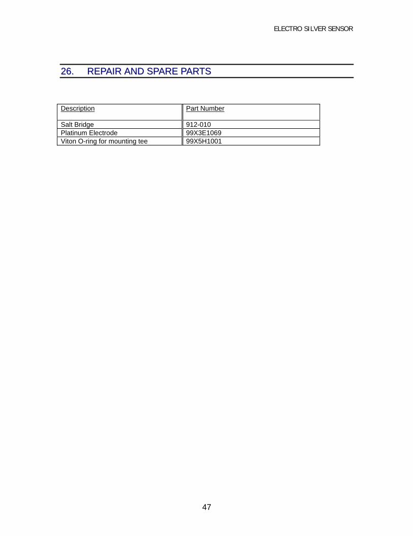
2266.. RREEPPAAIIRR AANNDD SSPPAARREE PPAARRTTSS
Description Part Number
Salt Bridge 912-010Platinum Electrode 99X3E1069Viton O-ring for mounting tee 99X5H1001

ELECTRO SILVER SENSOR
48
2277.. EELLEECCTTRRIICCAALL CCOONNNNEECCTTIIOONNSSThe sensor is electrically connected directly to the instrument or indirectly with a junction box andinterconnect cable.
27.1 Direct Hook-up
27.1.1 Route sensor cable to instrument. Use watertight connector, such as cable feed-thrufitting, in instrument’s cable entry hole.
27.1.2 Connect sensor cable lead wires in accordance with instrument hook-up diagram.NOTE:
If automatic temperature compensation is not desired, disconnect the yellow lead wireand tape its end. Connect a 1% 300 ohm , ¼ watt resistor between the designated yellowand black terminals in the instrument to simulate a fixed 25º temperature.
27.2 Indirect Hook-up with Junction Box
27.2.1 Mount junction box (with terminal strip ) on flat surface such that its cover is removablewhen installed.
27.2.2 Route sensor cable to junction box through watertight connector such as cable feed-thrufitting.
NOTE:Keep terminal strip dry to prevent problems caused by wet and/or corroded terminals.
27.2.3 Route interconnect cable to junction box and instrument. It is recommended that thiscable be run in ½” metal conduit for protection against moisture and mechanicaldamage. Use conduit hubs where cable enters junction box and instrument enclosure.
NOTE:Do not run line power in same conduit with interconnect cable (“electrical noise” mayinterfere with sensor signal).
27.2.4 Connect sensor and interconnect cable lead wires, by matching colors, to junction boxterminal strip. Fasten cover onto junction box.
27.2.5 Connect interconnect cable lead wires to instrument in accordance with instrument hook-up diagram.
NOTE:If automatic temperature compensation is not desired, disconnect the yellow interconnectcable lead wire and tape its end. Connect a 1%, 300 ohm, ¼ watt resistor between thedesignated yellow and black terminals in the instrument to simulate a fixed 25ºCtemperature.
27.3 MOUNTINGThe sensor and special mounting tee are factory-assembled. Unfasten the lock ring andremove the sensor from the mounting tee. Mount sensor vertically, electrodes down. Ifsensor must be installed on an angle, it should be at least 15º above horizontal. Other

ELECTRO SILVER SENSOR
49
mounting angles may cause erratic readings.
27.3.1 Install special 1-1/2” NPT mounting tee into a horizontal run of the sample or processline. Use thread sealant on mounting hardware threads to avoid leaks. Teflon tape orpipe sealant with Teflon (Loctite No. 59231 or equivalent) is recommended. Experienceindicates that Teflon tape may not provide an adequate seal, especially at higher solutiontemperatures.
27.3.2 Electrically connect sensor to instrument as described in the first paragraph, Section 27.
27.3.3 Remove protective plastic cap from sensor and calibrate the system with ORP referencesolution before mounting sensor into process line.
27.3.4 Insert sensor into mounting tee. Make sure O-ring is properly seated in its groove andtighten lock ring. This completes the installation.
FIGURE 27-1: Flow-Thru Sensor Assembly Details

ELECTRO SILVER SENSOR
50
2288.. RREEPPLLAACCIINNGG EELLEECCTTRROODDEESS
To replace the process (or standard) electrode, it’s not necessary to disconnect the sensor cableat the instrument A color coded quick-disconnect fitting is provided on each electrode head (redfor process electrode, blue for standard electrode).
28.1 Loosen lock ring and remove sensor from process.
28.2 Loosen cable feed-thru nut at top of sensor cover and push cable feed-thru grommetback 6 inches on sensor cable.
28.3 Unscrew and remove sensor cover.
28.4 Disconnect electrode cable from electrode head by twisting quick-disconnect fittingcounterclockwise and pulling apart all in one motion. Unscrew and remove the electrode.
28.5 Remove washer and small O-ring from electrode holder. Inspect O-ring for cuts, cracksand compressive deformation. Replace it if necessary (p/n 99X5H1004).
28.6 Apply silicone grease on small O-ring and place in its seat on electrode holder. Placewasher (p/n 99X5H1005) on O-ring.
28.7 Insert new electrode (process or standard) into electrode holder. Turn electrodeclockwise until fingertight. Then tighten ¼ turn more with pliers. Do not overtighten!
NOTE: New electrodes have an electrical connector protector in the head. This protectormust be removed before quick-disconnect fitting can be attached.
28.1 Sealant is not required on electrode threads. If sample or process line pressure willapproach 100 psig, it may be desirable at this time to check the electrode assembly forleaks. To do this, it is necessary to assemble electrode holder to flow-thru mounting teeand pressurize the system without the sensor cover in place. After the union andelectrode O-ring seals have been checked for leaks, the sensor cover and cable feed-thru fitting can be assembled.
28.2 Reconnect quick-disconnect fitting to electrode head by pushing and turning in onemotion.
NOTE: New electrodes have an electrical connector protector in the head. This protectormust be removed before quick-disconnect fitting can be attached.

ELECTRO SILVER SENSOR
51
28.3 Replace sensor cover and cable feed-thru fitting. Recalibrate the systembefore reinstalling sensor in the process.