fv1200mpe specifications n e w b system s system t … · multi photon laser scanning microscope...
TRANSCRIPT

Think Deep. Look Deeper... with Olympus.
Multi Photon Laser Scanning Microscope
FV1200MPEFLUOVIEW
NEW
NEW
NEW
N E W
NEW
NEW
NEW
N E WB system S system T system M system
Laser unit
IR pulsed laser with negative chirp for multi photon excitation
•Mode-locked Ti : sapphire laser [femtosecond laser (equipped with a group velocity compensation)], laser power unit, water-cooled circulating chiller •MaiTai BB DeepSee-OL, MaiTai HP DeepSee-OL or MaiTai eHP DeepSee-OL (Spectra-Physics products) MaiTai BB DeepSee-OL : 710nm — 990nm MaiTai HP DeepSee-OL : 690nm — 1040nm MaiTai eHP DeepSee-OL : 690nm — 1040nm (70 femtoseconds at a specimen plane)
Visible light laser AOTF laser combiner
LD laser: 405nm: 50mW, 440nm: 25mW, 473nm 15mW, 559nm 15mW, 635nm 20mWMulti Ar laser (458nm, 488nm, 515nm, Total 30mW), HeNe (G) laser (543nm, 1mW)Modulation: Continuously adjustable via an AOTF (0.1 — 100% in 0.1% increments)•Operating mode: Allows laser turn-off during the retrace period REX: adjustment of laser power for each region, and selection of the laser and selection of the laser wavelength•Visible light laser platform with implemented AOTF system, ultra-fast intensity control for individual laser lines, additional shutter control, Connected to scanner via single-mode fiber •Equipped with laser feedback mechanism to limit changes in laser light intensity over time
Single laser for visible light LD473 laser (15mW) Depending on the type of modulation: light intensity modulation, shutter control, connected to the scanner via single-mode optical fiber
Scanning unit
Scanning method •Light deflection via 2 silver-coated galvanometer scanning mirrors •Light deflection via 2 gold-coated galvanometer scanning mirrors
Scanning modes •Pixel size: 64 x 64 — 4096 x 4096 pixels Scanning speed: (pixel time): 2µs — 200µs High-speed scanning mode: 16 frames/s (256 x 256)•Dimensions: Time, Z, (wavelength) (or any combination thereof) •Line scan: straight line (includes rotation), free line, point XY scan
Zoom size Observation position zoom with inclination width modification of galvanometer mirror: 1—50x (adjustable in 0.1x increments)
Confocal detector(The M scanner does nothave a confocal detector)
•Detector: Multi alkali photomultiplier 3 channels, optional cooled GaAsP-PMT 2 channels detector or 4CH detector for expansion•Dichromatic mirrors for excitation, dichromatic mirrors for multi photon excitation, dichromatic mirrors for fluorescence, emission filter•Infrared cut filter: using a high-performance filter•A filter or spectral type of fluorescence detector can be selected Spectral type: Channels 1 and 2 provided with independent grating and slit Selectable wavelength range: 1 – 100nm, wavelength resolution: 2nm, wavelength switching speed: 100nm/ms•Pinhole: Single motorized pinhole, pinhole diameter: ø50 – 800µm (spectral type ø50 – 300µm), adjustable in 1µm increments•Field Number: 18
Optics with infrared laser for multi photon imaging •Integrates a multi photon near-infrared pulsed laser in the scanning unit (Laser safety measures implemented)•Continuously variable output using AOM (0.1 – 100%, 0.1% increments)
Component incorporating the laser for multi photon imaging Main scanner for observation SIM scanner for laser light stimulation, Main scanner for observation: VIS laser
Incorporating 2 independent lasers for laser light stimulation/observation M scanner for observation
Detector for multi photon imaging
Reflected light fluorescent detector
Multi alkali photomultiplier (2 or 4 channels) or Cooled GaAsP-PMT 2 channels plus Multi alkali photomultiplier 2 channels
Transmitted light fluorescent detector
Photomultiplier (2 channels),Fluorescence wavelength can be selected with the dedicated filter cube (replaceable) (not combinable with IX-SVL2) Exclusive equipment for the BX61WI upright microscope
Transmitted DIC unit •Integrated transmitted light detector and transmitted illuminator, Motorized switching Connected to microscope via fiber cable (IR-DIC observation using an infrared laser is not possible)
Z-drive •A motorized focus module inside the microscope is used•Minimum increment: 0.01µm
Microscope Upright microscopes: BX61WI, BX61 Inverted microscope: IX83 (IX83P2ZF)
System control •OS: Windows 7 Professional (English version) •CPU: Intel Xeon E5-1620 (3.60GHz) or higher •Memory: 8GB (2GB X 4) •Hard disk: 1TB or more for data storage •Dedicated I/F board: built-in control unit •Graphics board: NVIDIA Quadro 600 •Optical drive: DVD ± R/RW Super-Multi
Required installation environment Room temperature: 20 – 25°C, humidity: 75% or less@25°C, requires continuous (24-hour) power supply
Vibration isolation table for microscope and laser installation, size 1500mm x 1250mm 1500mm x 1500mm 1700mm x 1700mm 1500mm x 1250mm
Shinjuku Monolith, 3-1, Nishi Shinjuku 2-chome, Shinjuku-ku, Tokyo, Japan
3500 Corporate Parkway, Center Valley, Pennsylvania 18034-0610, U.S.A.
5301 Blue Lagoon Drive, Suite 290 Miami, FL 33126, U.S.A.
• OLYMPUS CORPORATION is ISO14001 certified.• OLYMPUS CORPORATION is FM553994/ISO9001 certified.• OLYMPUS CORPORATION is MD540624/ISO13485 certified.• Illumination devices for microscope have suggested lifetimes. Periodic inspections are required. Please visit our website for details.• All company and product names are registered trademarks and/or trademarks of their respective owners.• Images on the PC monitors are simulated.• Specifications and appearances are subject to change without any notice or obligation on the part of the manufacturer.
Printed in Japan M1762E-102012
FV1200MPE specifications
Reference material on cover page and page 13 upper: Hiroshi Hama, Hiroshi Kurokawa, Hiroyuki Kawano, Ryoko Ando, Tomomi Shimogori, Hisayori Noda, Kiyoko Fukami, Asako Sakaue-Sawano & Atsushi Miyawaki Scale: a chemical approach for fluorescence imaging and reconstruction of transparent mouse brain Nature Neuroscience, advance online publication, 30 August 2011 (doi:10.1038/nn.2928)
Image data on cover page provided by: Hiroshi Hama, Hiroshi Kurokawa, Atsushi MiyawakiLaboratory for Cell Function Dynamics RIKEN Brain Science Institute
1 2
Think Deep. Look Deeper... with Olympus.
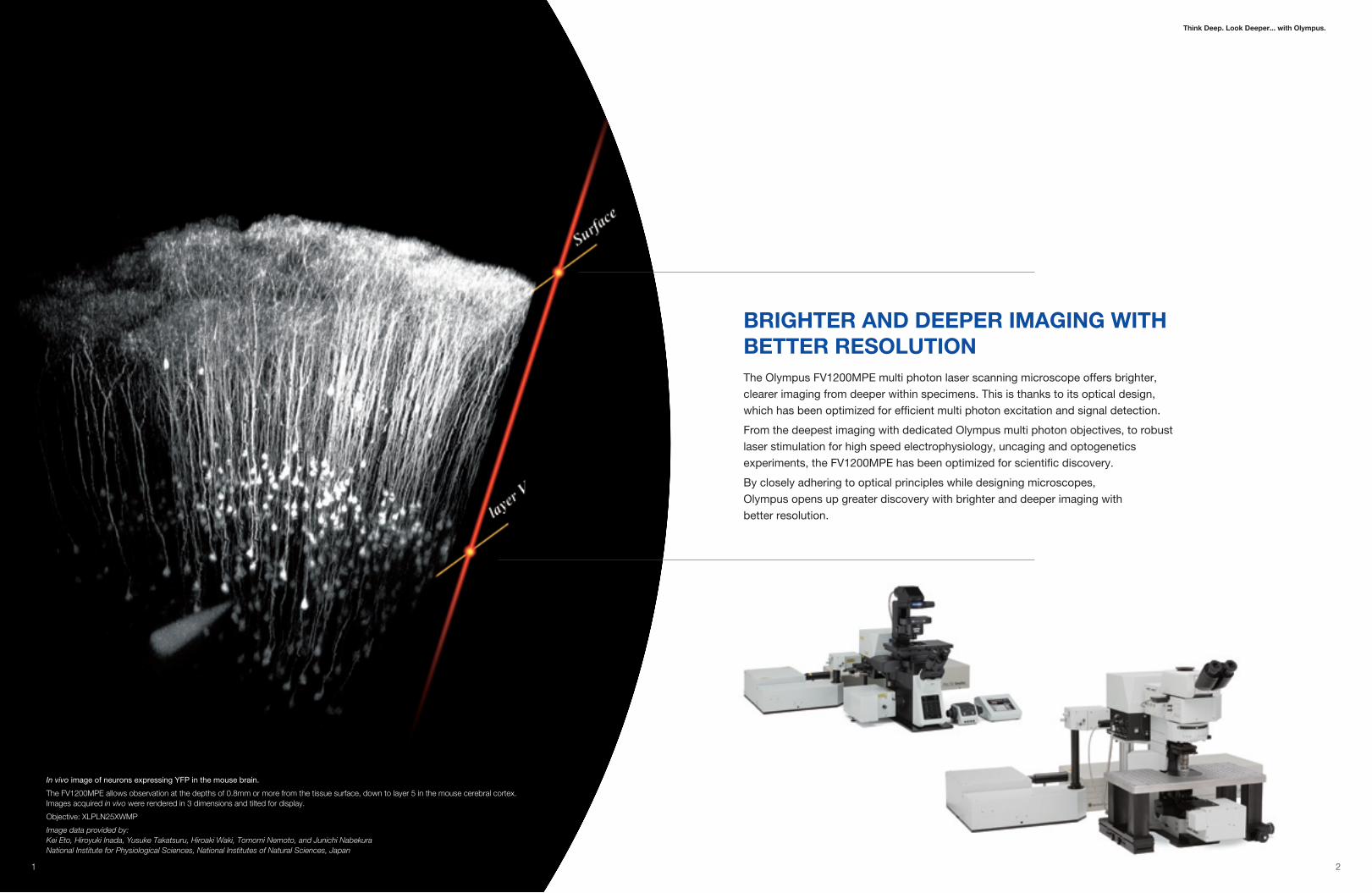
In vivo image of neurons expressing YFP in the mouse brain.
The FV1200MPE allows observation at the depths of 0.8mm or more from the tissue surface, down to layer 5 in the mouse cerebral cortex. Images acquired in vivo were rendered in 3 dimensions and tilted for display.
Objective: XLPLN25XWMP
Image data provided by: Kei Eto, Hiroyuki Inada, Yusuke Takatsuru, Hiroaki Waki, Tomomi Nemoto, and Junichi Nabekura National Institute for Physiological Sciences, National Institutes of Natural Sciences, Japan
BrighTer anD Deeper iMaging wiTh BeTTer reSOLuTiOnThe Olympus FV1200MPE multi photon laser scanning microscope offers brighter,
clearer imaging from deeper within specimens. This is thanks to its optical design,
which has been optimized for efficient multi photon excitation and signal detection.
From the deepest imaging with dedicated Olympus multi photon objectives, to robust
laser stimulation for high speed electrophysiology, uncaging and optogenetics
experiments, the FV1200MPE has been optimized for scientific discovery.
By closely adhering to optical principles while designing microscopes,
Olympus opens up greater discovery with brighter and deeper imaging with
better resolution.

3 4
The fv1200Mpe aLLOwS BrighT, high-reSOLuTiOn OBServaTiOn Deep wiThin SpeciMenS wiThOuT DaMaging TheM
1 2 3 4 5 6
6
7
Laser unit IR pulsed laser with negative chirp for multi photon excitation
lambda plate AOMAuto beam expander
Galvanometer mirrorDedicated objective for multi photon imaging
Specimen
Reflected fluorescence light detector for multi photon imaging
High NA condenserTransmitted fluorescence light detector for multi photon imaging
Brighter and Deeper imaging with Less Damage
In multi photon microscopy, fluorescence excitation efficiency is maximized by using a short pulse width in the focal plane. However, the pulse width of a femtosecond laser disperses as it passes through optics, broadening the pulse width when the beam exits from an objective.The laser beam-shaping optics establish a compensatory dispersion, the exact inverse of that produced by the microscope's optics (negative chirp), thus restoring the ideal pulse width for the specimen.
1 2 3
5
64
7
custom Light adjustment for the exiting Laser Beam
The FV1200MPE is equipped with an AOM to adjust laser light. The AOM allows changes in laser intensity and rapid ON/OFF switching of the laser to microsecond control. This provides laser output control to restrict irradiation to the region of interest, avoiding surrounding areas. In thick specimens, laser intensity, and PMT voltages, can be adjusted with specimen depth allowing image capture without changes in image brightness.
auto-adjustment of the Beam in accordance with the excitation wavelength and Objective
To achieve efficient multi photon excitation, the laser beam, described by a Gaussian distribution of intensity, must fill the pupil diameter as it enters the objective.The beam expander of the FV1200MPE automatically adjusts the beam diameter depending on the objective and excitation wavelength. This optimizes laser beam characteristics for multi photon excitation microscopy.
correcting for Light refraction in the Specimen and providing Deep imaging
Refraction index differences within the specimen create a problem in deep imaging by disrupting the focal spot.The FV1200MPE’s dedicated objective compensates for the refractive index mismatches thanks to its correction collar, allowing the formation of an ideal focal spot deep within the specimen without loss of energy density.
wide field of view Design to Detect fluorescence with Minimal Loss of Scattered Light
In multi photon excitation, fluorescence is emitted from the focal spot inside the specimen. Cells and tissue components scatter light such that it emerges from the surface of the specimen at some distance from the incident beam. Incorporating a wide field of view, the FV1200MPE can capture the maximum amount of fluorescent signal, including scattered light, to provide highly efficient fluorescence imaging in scattering tissue.
new galvanometer Mirror Delivers 50% greater excitation efficiency due to nonlinear excitation
Our galvanometer mirror features an innovative silver coating that delivers outstanding reflective characteristics across a bandwidth from visible light to near infrared. The total reflectivity rate of the XY scanner is also improved—providing as much as 25% greater reflectivity in the near infrared range compared to conventional aluminum mirrors. And where absolute power is essential, the increase in reflectivity translates into a 50% improvement in multi photon excitation frequency compared to the FV1000MPE, making the mirror ideal for deep observation.
even Brighter in-depth Observation with Transmitted Light Detection
A transmitted fluorescence light detector for multi photon imaging with a dedicated high NA condenser detects transmitted fluorescence as well as transmitted laser light and forward scattered fluorescence. These additions allow extremely bright fluorescence imaging deep within a specimen and is especially effective for second harmonic generation (SHG) imaging.
Auto beam expander (simplified example )
Gaussian distribution of illumination
With correction Without correction
Large Small
Field number for the
detection end
High NA condenser
Transmitted fluorescence light detector for multi photon imaging
1
2
3
6
5 6
7
400 500 600 700 800 900 100 1100
1009080706050403020100
Wavelength [nm]
Silver coating
Aluminum coating
Ref
lect
ance
[%]
4

5 6
DeDicaTeD OBJecTiveS anD high-SenSiTiviTY MuLTi phOTOn fLuOreScence DeTecTOrS
XLpLn25XwMp, Dedicated water immersion Objective with exceptional Brightness and resolution for Multi photon imagingThis water immersion objective with a high NA and wide fi eld of view design has improved near-infrared transmittance to optimize multi photon fl uorescence microscopy. The correction collar minimizes spherical aberration caused by refractive index differences between water and the specimen. This allows the formation of a tightly focussed spot without reducing energy density during deep imaging. Its wide fi eld of view design and effi cient capture of scattered fl uorescence allows for extremely bright, high-resolution fl uorescence microscopy. In addition, it provides an approach angle of 35 degrees while maintaining a high NA, allowing easy access to execute simultaneous patch clamping and imaging.
35˚W.D. 2mm
NA 1.05•Sharp approach angleAn approach angle of 35 degrees provides easy access for patch clamping. Use of this dedicated objective for multi photon imaging allows simultaneous imaging and patch clamp recordings.
•wide field of viewDespite efficient excitation, fluorescence is scattered deep within the specimen. This widefield objective can collect scattered fluorescence to generate brighter images.
•highly focused Light Deep within the SpecimenIn this example, fluorescent microspheres 0.5µm in diameter were observed in a highly refractive medium. Axial resolution has been markedly improved compared to conventional 20x objective.
Silicone immersion Objectives for Live imagingThis immersion objective is designed exclusively for use with silicone oil, which has a refractive index even closer to live cells than that of water. The objective features a large numerical aperture and wide-ranging transmission capability from UV to IR for use in both multi photon and single photon microscopy. Time-lapse observations become more reliable and less elaborate, because silicone oil does not dry at 37ºC and its refractive index remains constant. This objective also offers a long working distance to
Silicone immersion ObjectiveupLSapO30XSMagnification: 30xNA: 1.05 (silicone immersion oil)W.D.: 0.8mmCover glass thickness: 0.13–0.19mmOperation temperature: 23ºC–37ºC
Cover glassne≈1.52
Silicone oilne≈1.40
Waterne≈1.33
Specimenne≈1.38
refractive index is important with Deep Tissue Observation
When working with a water immersion objective, the difference between the refractive index of the sample and water results in spherical aberration in deep tissue, causing resolution to deteriorate and fluorescence to become dim.
Water immersion objective
When working with a silicone immersion objective, the difference between the refractive index of the sample and silicone oil is minimal. So it achieves brighter fluorescence images with higher resolution for deep tissue.
Silicone immersion objective
Correction Collar is used to adjust for refractive index mismatch with water immersion objective XLPLN25XWMP.
enable observation at deeper tissue levels and across broader fi elds. In a nutshell, this silicone objective offers a comprehensive solution for both macro- and deep-tissue observation in the fi elds of generative and regenerative science.
Model Numerical Aperture Working Distance (mm) MPLN5X 0.10 20.0 UMPLFLN10XW 0.30 3.5 UMPLFLN20XW 0.50 3.5 LUMPLFLN40XW 0.80 3.3 LUMPLFLN60XW 1.00 2.0 LUMFLN60XW 1.10 1.5 XLUMPLFLN20XW*1 1.00 2.0 XLPLN25XWMP*1 1.05 2.0 XLPLN25XSVMP*1 1.00 4.0 UPLSAPO60XW 1.20 0.28
Model Numerical Aperture Working Distance (mm) UPLSAPO10X2 0.40 3.1 UPLSAPO20X 0.75 0.6 UPLSAPO30XS 1.05 0.8 UPLSAPO40X2 0.95 0.18 UPLFLN40XO 1.30 0.2 UPLSAPO40XS*2 1.25 0.3 UPLSAPO60XO 1.35 0.15 UPLSAPO60XW 1.20 0.28 UPLSAPO60XS 1.30 0.3
Objectives for BX61wi Objectives for iX83
*1 Exclusively for BX61WI confi guration.
refl ected high-sensitivity gaasp Detector for upright MicroscopeAchieve images with a high S/N ratio, even in cases of extremely faint fl uorescence, with a detector that makes use of hand-selected gallium arsenide phosphide (GaAsP, with 45% QE). What’s more, while this detector offers superior photon detection effi ciency compared to conventional PMTs, noise is kept to an absolute minimum through the advantage of Peltier cooling.•Features a choice of two conventional PMT channels and two GaAsP PMT channels—enabling easy fl uorescence imaging by simply switching between channels. Select a conventional PMT channel for identifi cation of the imaging site. Switch to a GaAsP PMT channel for high-sensitivity imaging with a high S/N ratio.•Keeps noise to an absolute minimum, with GaAsP PMT channels cooled by a Peltier element.•Reduces degradation caused by ambient light, such as room lighting or excessive fl uorescence.
CH2
CH3
CH3
CH1
CH1
CH4
CH2
CH4
Arc-dVenus transgenic mouse (8-week-old), coronal brain block, hippocampal dentate gyrus Projection image of 300-400µm depth (5µm steps)
Image data provided by: Dr. Norio Takata, Dr. Hajime Hirase Laboratory for Neuron-Glia Circuitry, RIKEN BSI
Dr. Shun Yamaguchi Gifu University Graduate School of Medicine
Image captured with current detector Image captured with GaAsP detector
refl ected fluorescence Light DetectorFluorescent signals are not only extremely faint, but also scatter within a thick specimen, causing further decay in signal intensity. The FV1200MPE uses a detector installed at a position as close as possible to the specimen in order to maximize detection effi ciency. Because multi photon excitation is restricted to the focal plane, the emitted fl uorescence does not need to pass through a confocal aperture (pinhole). This allows high-sensitivity imaging minimizing light loss due to scattering.•In addition to the standard 2 channel type equipped with 2 photomultiplier tubes, a 4 channel refl ected fl uorescence light detector for multi photon imaging is available. All detectors are located equidistant from the specimen and allow bright, high-sensitivity multicolor imaging.•Olympus’ own high-performance fi lter is used for wavelength separation. It can be replaced with other fi lters depending on the fl uorescence characteristics of the specimen.
Two-photon imaging of an explanted lymph node following transfer of B lymphocytes labeled with either Snarf (red) or cMac (blue). The transferred cells and autofluorescence (green) can be observed through the collagen rich capsular region to a depth greater than 250µm. The left panel depicts the z-projection of an image stack at between 200 and 250µm depth. The right panel shows the 100µm y-projection of the same stack resliced along the xz-plane. Excitation at 800nm, objective XLPLN 25XWMP, NA 1.05.Julia Eckl-Dorna, Patricia Barral, Andreas Bruckbauer, Facundo BatistaCancer Research UK, London Research Institute, London, UK
reflected fluorescence light detector for multi photon imaging
configuration example for iX83, 4ch
configuration example for BX61, 4ch
*2 Scheduled to be available on 2013.
7 8
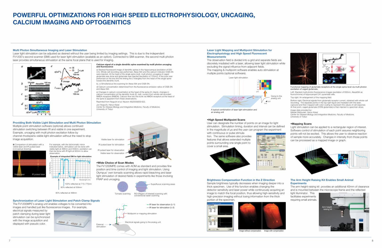
pOwerfuL OpTiMiZaTiOnS fOr high SpeeD eLecTrOphYSiOLOgY, uncaging, caLciuM iMaging anD OpTOgeniTicS
Multi photon Simultaneous imaging and Laser StimulationLaser light stimulation can be adjusted as desired without the user being limited by imaging settings. This is due to the independent FV1200’s second scanner (SIM) used for laser light stimulation (available as an option). Connected to SIM-scanner, the second multi photon laser provides simultaneous stimulation at the same focal plane that is used for imaging.
calcium signal of a single dendritic spine examined by multi photon uncaging and fluorescence
a) Stacked fluorescent image of dendritic spines in the hippocampus (excitation of 830 nm). Whole-cell recording was performed. Alexa 594 and the calcium indicator OGB-5N were injected. At the head of the single spine (red), multi photon uncaging of caged glutamate was done and glutamate was injected (excitation of 720nm). A line scan was performed on the line (the line linking the 2 triangles) from the head of this single spine toward the dendritic trunk.
b), c) Simultaneous line scanning for Alexa 594 and OGB-5N.
d) Calcium concentration determined from the fluorescence emission ratios of OGB-5N and Alexa 594.
e) Changes in calcium concentration at the head of the spine (H, black), changes in calcium concentration at the dendritic trunk (D, red), current from whole-cell recorded NMDA receptors (INMDA). Calcium flow into the trunk via NMDA receptors at the head of the spine is apparent from these observations.
Reprinted from Noguchi et al. Neuron 46(2005)609-622.
Jun Noguchi, Haruo KasaiCenter for Disease Biology and Integrative Medicine, Faculty of Medicine,University of Tokyo
Tornado scanning ROI (Region of Interest) scanning with conventional raster scanning
Superfluous scanning areas
Synchronization of Laser Light Stimulation and patch clamp SignalsThe FV1200MPE's analog unit enables voltages to be converted into images and handled just like fl uorescence images. For example, electrical signals measured by patch clamping during laser light stimulation can be synchronized with the image acquisition and displayed with pseudo color.
providing Both visible Light Stimulation and Multi photon StimulationMultiple point stimulation software (optional) allows continued stimulation switching between IR and visible in one experiment. Example, uncaging with multi photon excitation follow by channel-rhodopsins visible light stimulation without the need to stop image acquisition.
100% reflected at 715–770nm
80% reflected at 559nm
80% reflected at 488nm
Multipoint or mapping stimulation
Electrical signals going to the analog unit
— IR laser for observation (λ-1)
— IR laser for stimulation (λ-2)
■ Comparison of stimulation with a visible laser and IR pulsed laser (conceptual drawing)
For example, with the dichromatic mirror indicated below, stimulation can be done with visible light at 488nm and 559nm; excitation can then be done with IR light at 920nm to allow observation.
3500
10
20
30
40
50
60
70
80
90
100
400 450 500 550 600 650 700 750
Example of integrated DM for light stimulation
800 850 900 950 100010501100
Transmittance (%
)
Wavelength (nm)
Visible laser for stimulation
IR pulsed laser for stimulation
IR pulsed laser for observation
Visible laser for observation
•Wide Choice of Scan ModesThe FV1200MPE comes with AOM as standard and provides fi ne position and time control of imaging and light stimulation. Using Olympus’ own tornado scanning allows rapid bleaching and laser light stimulation of desired fi elds in experiments like those involving FRAP and uncaging.
External stimulation
Brightness compensation function in the Z DirectionSample brightness typically decreases when imaging deeper into a thick specimen. Use of this function enables changing the detector sensitivity and laser power while continuously acquiring an image to match the focal position, thus allowing high-sensitivity and high-precision imaging without losing information from the thick portion of the specimen.
The arm height raising Kit enables Small animal experimentsThe arm height raising kit provides an additional 40mm of clearance and is mounted between the microscope frame and the refl ected light illuminator. This facilitates experiments requiring small animals.
Laser Light Mapping and Multipoint Stimulation for electrophysiology and high Speed fluorescent MeasurementsThe observation fi eld is divided into a grid and separate fi elds are discretely irradiated with a laser, allowing laser light stimulation while excluding the signal infl uence from adjacent fi elds. The mapping & multipoint software enables auto stimulation at multiple points (optional software).
•High Speed Multipoint ScansUser can designate the number of points on an image for light stimulation. Stimulation timing, duration and interval can be defi ned in the magnitude of µs and the user can program the experiment with continuous or pulse stimula-tion. The same software also provides features that allows extended multiple points surrounding one single point to cover a small area.
Functional mapping of glutamate receptors at the single spine level via multi photon excitation of caged glutamate.
Left: Stacked multi photon fluorescence images (excitation of 830nm, Alexa594 as fluorochrome) of hippocampal CA1 pyramidal cells.
Top right: An enlargement of the mapping field.
Bottom right: Electrical signals from glutamate receptor current, obtained with whole-cell recording. The separate points in the top right figure are irradiated with the laser, captured and then mapped with color-coding to represent the values of cell response. At that point, caged glutamate (CDNI-glutamate) is then injected to specimen slices.
Image data provided by:Masaki Matsuzaki, Haruo KasaiCenter for Disease Biology and Integrative Medicine, Faculty of Medicine, University of Tokyo
Visible laser IR pulsed laser
Going to the analog unit
A typical combination of laser light stimulation and an analog unit
05
1020
30
40(pA)
10pA1mA
Laser light stimulation
Arm height raising kit
Image without compensation Image with compensation
0
50.0
100.0
150.0
200.0
250.0
300.0
350.0
400.0
450.0
500.0
550.0
600.0
650.0
700.0
750.0
800.0
850.0
900.0
950.0
1000.0
1050.0
1000 2000 3000 4000 5000 6000Time(µs)
Inte
nsity
7000 8000 9000 100001100012000
•Mapping ScansLight stimulation can be applied to a rectangular region of interest. Software control of stimulation of each point assures neighboring points will not be excited. This allows the user to observe reaction of sample more accurately. Changes in intensity from those points can be processed as a mapped image or graph.

9 10
applications
Left: fluorescence angiogram in the brain of a living mouse represented by a maximum intensity projection of the imaging volume of ~600 x 600 x 600 microns. The imaging was performed on a transgenic mouse that develops senile plaques similar to those found in case of Alzheimer's disease. They are labeled with the fluorescent compound methoxy-XO4 (blue).
Right: a group of neurons and astrocytes loaded with the intracellular calcium reporter OGB-1 (green). Astrocytes are labeled with SR101 (red). Astrocytes that are loaded with OGB and tagged with SR101 are yellow.
Image data provided by: Brian J. Bacskai, PhD Alzheimer's Disease Research Unit, Mass. General Hospital
In vivo observation inside the brain of a GFP-actin transgenic mouse.
One hundred and three minutes after a low concentration of lipopolysaccharide was intravenously injected into the mouse, attachments between epithelial cells detached (arrow) and a thrombus formed (triangle).
Image data provided by: Hisako Nakajima, Akira Mizoguchi Neural regeneration and cell communication, Genomics and regenerative biology, Mie university graduate school of medicine
3-dimensionally constructed images of neurons expressing EYFP in the cerebral neocortex of a mouse under anesthesia.
Cross-sectional images down to 0.7mm from the surface can be observed after attachment of a special adapter to the specimen.
Objective: LUMPlanFL 60XW/IR
Image data provided by: Hiroaki Waki, Tomomi Nemoto, and Junichi Nabekura National Institute for Physiological Sciences, National Institutes of Natural Sciences, Japan
Z-stack image of neurons and glial cells in layers II and III of the cerebral cortex of a rat under anesthesia.
Magenta: glial cells (astrocytes) marked by specific fluorescence marker Sulforhodamine 101, Green: neurons and glial cells, Ca-sensitive fluorescent dye Oregon Green 488 BAPTA-1 200µm.
Image data provided by: Norio Takata, Hajime Hirase Neuronal Circuit Mechanisms Research Group, Riken Brain Science Institute, Japan
Living pancreatic islet of Langerhans stained with FM1-43 lipid-soluble fluorescent dye.The cell membrane structure of the islet of Langerhans and growth of the membrane area accompanying insulin exocytosis of a single insulin granule can be observed.
Image data provided by: Noriko Takahashi, Haruo Kasai Center for Disease Biology and Integrative Medicine, Faculty of Medicine, University of Tokyo
Observation of neurogenesis in the early mouse retina
Whole-mount specimen of the mouse retina in which mitotic progenitor cells are stained with Alexa488 (green) and neurons are stained with Alexa568 (red). Using this specimen, images were superimposed after about 120 cross sectional images were acquired. (with XLPLN25XWMP objective and excitation wavelength of 890nm)
Observation of the retina in which rod photoreceptors were labeled with EGFP (green) and ubiquitous retina cells were labeled with tdTomato (red).
The specimen was fixed for a short period of time, but images were acquired under conditions for live cell imaging (low laser power) (with an XLPLN25XWMP objective and excitation wavelength of 890nm).
Specimens provided by: Dr. Branden R. Nelson, PhD at the University of Washington
Transgenic zebrafish with cell membranes labeled with CFP. CFP is shown in green and YFP in magenta.
Image data provided by: Dr. Rachel O Wong, Mr. Philip Williams, Dept. Biological Structure, University of Washington
3-dimensionally constructed image of cGMP-containing cells marked with CY3 located along the antenna nerve of the silkworm.
200µm projection image.
Image data provided by: Hitoshi Aonuma, Research Institute for Electronic Science, Hokkaido University, Japan
Mouse Brain Mouse retina Silkworm
▲
rat Brain Mouse Spleen
Zebrafish
BFPCFPEGFPEYFPSapphireDsRedCalcein-BlueCalcein-GreenCa-Green 5NCa-OrangeCa-CrimsonFluo-3, Fluo-4Indo-1 (when Ca-bound)Indo-1 (Ca-free)Fura (when Ca-bound)
Fura (Ca-free)Caged CaMag-FuraCascade-BlueCoumarin AMCADAPIHoechstBodypy-FLFITCRH-795RhodamineDiIDiDLucyfar-YellowAlexaFluor488AlexaFluor594(Uncaging wavelength) Caged glutamate
(Uncaging wavelength) Caged Ca(Laser light stimulation wavelength) Kikme
700
750
800
850
900
950
1000
Fluorochrome Excitation wavelength (nm)
ReferencesXu, C. and W. W. Webb, J. Opt. Soc. Am. B 13 (3), 481-491, 1996. Xu, C., W. Zipfel, J.B. Shear, R.M. Williams and W.W. Webb, PNAS 93(20), 10763-10768, 1996 Xu, C., R.M. Williams, W.R. Zipfel and W.W. Webb, Bioimaging 4(3), 198-207, 1996 Heikal, A.A., S.T. Hess, G.S. Baird, R.Y. Tsien and W.W. Webb, PNAS97(22), 11996-12001, 2000
appLicaTiOn

11 12
Lineup
a varieD Lineup fOr LaSer LighT STiMuLaTiOn anD in-DepTh OBServaTiOn, frOM in vivo TO Live ceLL iMaging
M Scanner Multi photon exclusive SystemThis multi photon exclusive system is not equipped with visible light lasers. Simple optics optimized for multi photon microscopy allow a smaller size, simpler operation, and deeper imaging within the specimen. The system uses a gold-coated galvanometer scanning mirror.
Standard Scanner Multi photon Microscopy SystemThis system is equipped with an IR laser for multi photon imaging and laser for visible light, so it is designed for deep imaging by multi photon microscopy and confocal imaging with a visible laser. The system is designed for a variety of imaging including Live Cell and in vivo imaging.* Using this system along with the double laser combiner allows multi photon imaging and visible light stimulation.
Multi photon Laser Light Stimulation SystemThis system is equipped with an IR laser delivering the light to the scanner for stimulation. In addition to general multi photon microscopy, the system allows pinpoint light stimulation by multi photon excitation during imaging with a visible laser.*Multi photon microscopy does not allow some image acquisition modes such as Time Controller.
Multi photon imaging plus Multi photon Laser Light Stimulation SystemThis system synchronizes laser light from 2 independent IR lasers for stimulation and imaging. It provides the multi photon imaging capability of visualizing deep within the tissue, while at the same time, enabling pinpoint 3D stimulation with multi photon excitation. eg. stimulate a single dendritic spine located deep within the tissue. The newly introduced SIM dual port feature allows the SIM scanner to accurately stimulate with both visible laser as well as IR laser.
M System (Multi photon exclusive System) Laser Sharing System
Red: IR pulsed laser, Green: Fluorescent lightBX61/IX83 configuration
BX61/IX83 configuration
BX61/IX83 configuration
BX61/IX83 configuration
Red: IR pulsed laser, Blue: Visible light laser, Green: Fluorescent light
B System (Basic System)
S System (Stimulation System)
Red: IR pulsed laser (for stimulation/observation), Blue: Visible light laser, Green: Fluorescent light
Red: IR pulsed laser (for observation), Yellow: IR pulsed laser (for stimulation), Blue: Visible light laser, Green: Fluorescent light
T System (Twin System)
608 575
610
1250
900
2883
Laser power source equipped with chiller
PC rack
608
1250
1800
900
900
2883
1500
Unit: mm1500
610
1250
608 575
2883
900
900
1800
Laser power source equipped with chiller
Laser rack for visible light lasers
PC rack
1250
608
2883
1500
900
900
1800
Unit: mm1500
608
2883
2050
1800
900
900
1500
1500
Unit: mm608
575
1500
2883
900
900
1800
2050
610
1500
Laser power source equipped with chiller
Laser rack for visible light lasers
PC rack
608
575
1700
3658
2250
1800
900
900
608
1700
3083
2250
1800
900
900
1700
Unit: mmLaser power source equipped with chiller
575
610
1700
Laser power source equipped with chiller
Laser rack for visible light lasers
PC rack
This System allows 2 Microscopes to Share a Single Laser.
Example of a B system (Basic system) sharing a laser with an M system (Multi photon exclusive system)
Both the B system’s BX61WI and M system’s BX61WI share a single laser.
Example of a T system (Twin system) sharing lasers with a B system (Basic system)
The BX61WI in the B system and IX83 in the T system share 2 lasers.
visible Lasers use for Single photon confocal imagingThe multi-combiner enables combinations with all of the following diode lasers: 405nm, 440nm, 473nm, 559nm and 635nm. The system can also be equipped with conventional Multi-line Ar laser and HeNe-G laser.
Double output typeThe multi-combiner outputs laser light with two fibers. Light can be used for both observation and laser light stimulation.
Single output typeThe multi-combiner with a single output fiber for visible light observation. AOTF is standard equipment.
Optics adapted following LasersThe MaiTai BB/HP/eHP DeepSee-OL lasers (from Spectra Physics, a division of Newport Corporation) are designed exclusively for the FV1200MPE, to provide optimal multi photon performance.
Recommended system combinationsBXM-BXB system (BX61WI-M & BX61WI-B)IXB-BXB system (IX83-B & BX61WI-B)BXT-BXB system (BX61WI-T & BX61WI-B)BXT-IXB system (BX61WI-T & IX83-B)
Manufacturer Model Wavelength coveredSpectra-Physics MaiTai BB DeepSee-OL 710nm — 990nm
MaiTai HP DeepSee-OL 690nm — 1040nmMaiTai eHP DeepSee-OL 690nm — 1040nm
MaiTai DeepSee

13 14
Transmitted fluorescence Light DetectorA high NA condenser and transmitted fluorescence light detector for multi photon imaging detect fluorescence emitted from the focal plane and light scattered within the specimen. With this transmitted light detector, fluorescence can be detected with a high level of efficiency, especially in deep layers of the specimen.•The transmitted fluorescence light detector has 2 channels. These 2 channels can be used to detect fluorescence or SHG. Taking into account the reflected fluorescence light detector, FV1200MPE allows maximum 6-channel simultaneous acquisition.•Two types of dichromatic mirrors are available: one is a fluorescence collection type for wavelength separation in 2 channels and another for fluorescence and SHG (475nm).•Two types of condensers are available: one with an oil top lens for high NA (NA 1.45) and another with a dry top lens (NA 0.8).•Switching between transmitted light fluorescence detection and DIC observation is easy. This is optimal for patch clamping (transmitted light fluorescence detection and DIC observation cannot be performed simultaneously).
Dedicated high na condenser
CH1
CH2
BX61wi configuration
Second Harmonic Generation imaging of neurons.
A: SHG image of neurons in dissociated culture from the mouse cerebral cortex. After FM4-64 was injected to neurons, the cells were irradiated with a femtosecond laser at 950nm and the SHG signal at 475nm was detected with the transmitted light detector.
B: Zoomed fragment (5x) of the specimen in the yellow box in image A. As it is apparent, spines protruding from dendrites can be observed with fluorescent.
C: SHG and multi photon images have been superimposed.
Image data provided by: Mutsuo Nuriya, PhD, Masato Yasui, MD, PhD Department of Pharmacology School of Medicine, Keio University
Optical clearing agent ScaLeview-a2SCALEVIEW-A2 revolutionizes the imaging of formalin-fixed specimens.Simply render mammalian brain tissue transparent through immersion in SCALEVIEW-A2 solution. Because SCALEVIEW-A2 eliminates light scattering, it doesn't decrease the intensity of signals emitted by fluorescent proteins in the tissue and so enables structures labeled with fluorescent proteins to be imaged in detail from the surface to significant depth, without the need for mechanical sectioning.
SCALEVIEW-A2 contains the fundamental components of ScaleA2 developed by the RIKEN Institute. It is adjusted to achieve the optimal performance with the XLPLN25XSVMP objective.
ScaLeview immersion 25x objective XLpLn25XSvMpSpecially designed to deliver optimum performance with SCALEVIEW immersion, this dedicated multi photon objective with an ultra-long working distance enables high-precision imaging of transparent biological specimens to a depth of 4mm.
example of ultra-deep imaging of a transparent specimen
principleLineup
Take imaging to new Depths with Transparent Specimens and a Dedicated Multi photon ObjectiveOlympus makes it possible to perform high-precision imaging of transparent biological specimens at exceptionally deep tissue levels, with an innovative solution: comprising a dedicated 4mm working distance objective for multi photon imaging and a groundbreaking aqueous agent that renders biological specimens transparent.
A B C
Rendered transparent
920nm Laser
Objective
4.0mm
0mm
1mm
2mm
3mm
4mmYFP-H mouse cerebrum
Image data provided by : Hiroshi Hama, Hiroshi Kurokawa, Atsushi Miyawaki Laboratory for Cell Function Dynamics, RIKEN Brain Science Institute
Pial Surface
IV
V
VI
White Matter
CA1
DG
Single photon Multiple photons
Multi photon principleMulti photon excitationA laser radiates high-density light at wavelengths up to up to several times longer (approx.) than the emission wavelength, exciting the fluorescence of molecules located exactly at the focal point only. Confocal-type optical sectioning can be achieved without the use of a pinhole, since flurophores are not excited from areas outside the focal plane.
Single photon Multi photonSingle photon Multi photon
Excitation light Excitation light
Confocal laser microscopeSingle photon
Multi photon laser microscopeMulti photon
Fluorescent light Fluorescent light
Focal point
Pinhole
Photomultiplier
Multi photon imageSingle photon image
Tomomi Nemoto National Institute for Physiological Sciences, National Institutes of Natural Sciences, Japan
Haruo Kasai Center for Disease Biology and Integrative Medicine, Faculty of Medicine, University of Tokyo, Japan
A regular molecular (crystal) structure
what is Second harmonic generation (Shg)?SHG is a secondary nonlinear optical phenomenon. In SHG, the energy of 2 photons entering a specimen is combined, producing energy in the form of light. That is, the wavelength of light observed is half of the incident wavelength (the frequency is doubled). An SHG signal is not produced unless molecules in the material are noncentrosymmetric (i.e. a center of inversion symmetry is absent). The signal is linear, so a transmitted light detector is needed. In addition, SHG signal intensity is proportional to the size of the potential, so changes in membrane potential in the vicinity of lipid bilayers of cells with a regular molecular structure can also be analyzed.
SHG wave wavelength: 1/2 λ, energy: 2E( )
Incident light wavelength: λ, energy: E( )
The cerebral cortex of M-line, a strain of transgenic mouse (GFP), was exposed and in vivo Z-stack imaging was performed with excitation at 488nm for single photon excitation and with excitation at 920nm for multiple photons. With single photon, depths to only 250µm can be observed, but with multiple photons depths to about 750µm can be observed.
Images were acquired at a Live cell imaging seminar (National Institute of Advanced Industrial Science and Technology, Tsukuba Research Center).
Specimens provided by: Kimihiko Kameyama, Tomoyo Ochiishi, Kazuyuki Kiyosue, Tatsuhiko Ebihara Molecular Neurobiology Group, Neuroscience Research Institute, National Institute of Advanced Industrial Science and Technology, Japan
Deep Observation using Multi photon excitation
3D image 3D image
45µm
160µm
510µm
0µm
250µm
500µm
750µm
TaKe a revOLuTiOnarY apprOach TO Deep iMaging
The MuLTi phOTOn principLe