fuzzy logic control for multiresolutive adaptive pn ...cdn.intechweb.org/pdfs/34212.pdf0 fuzzy logic...
TRANSCRIPT

0
Fuzzy Logic Control for Multiresolutive AdaptivePN Acquisition Scheme in Time-Varying
Multipath Ionospheric Channel
Rosa Maria Alsina-Pages, Claudia Mateo Segura,
Joan Claudi Socoró Carrié and Pau BergadaLa Salle - Universitat Ramon Llull
Spain
1. Introduction
Communication with remote places is a challenge often solved using satellites. However,when trying to reach Antarctic stations, this solution suffers from poor visibility range andhigh operational costs. In such scenarios, skywave ionospheric communication systemsrepresent a good alternative to satellite communications.
The Research Group in Electromagnetism and Communications (GRECO) is designing an HFsystem for long haul digital communication between the Antarctic Spanish Base in LivingstonIsland (62.6S, 60.4W) and Observatori de l’Ebre in Spain (40.8N,0.5E) (Vilella et al., 2008). Themain interest of Observatori de l’Ebre is the transmission of the data collected from the sensorslocated at the base, including a geomagnetic sensor, a vertical incidence ionosonde, an obliqueincidence ionosonde and a GNSS receiver. The geomagnetic sensor, the vertical incidenceionosonde and the GNSS receiver are commercial solutions from third parties. The obliqueincidence ionosonde, used to sound the ionospheric channel between Antarctica and Spain,was developed by the GRECO in the framework of this project.
During the last Antarctic campaign, exhaustive measurements of the HF channelcharacteristics were performed, which allowed us to determine parameters such asavailability, SNR, delay and Doppler spread, etc. In addition to the scientific interest ofthis sounding, a further objective of the project is the establishment of a backup link fordata transmission from the remote sensors in the Antarctica. In this scenario, ionosphericcommunications appear to be an interesting complementary alternative to geostationarysatellite communications since the latter are expensive and not always available fromhigh-latitudes.
Research work in the field of fuzzy logics applied to the estimation of the above mentionedchannel was first applied in (Alsina et al., 2005a) for serial search acquisition systems inAWGN channels, afterwards applied to the same channel but in the multiresolutive structure(Alsina et al., 2009a; Morán et al., 2001) in papers (Alsina et al., 2007b; 2009b) achievinggood results. In this chapter the application of fuzzy logic control trained for Rayleighfading channels (Proakis, 1995) with Direct-Sequence Spread-Spectrum (DS-SS) is presented,specifically suited for the ionospheric channel Antarctica-Spain. Stability and reliability of thereception, which are currently being designed, are key factors for the reception.
7
www.intechopen.com

2 Will-be-set-by-IN-TECH
It is important to note that the fuzzy control design presented in this chapter not only resolvesthe issue of improving the multiresolutive structure performance presented by (Morán et al.,2001), but also introduces a new option for the control design of many LMS adaptivestructures used for PN code acquisition found in the literature. (El-Tarhuni & Sheikh, 1996)presented an LMS-based system to acquire a DS-SS system in Rayleigh channels; years after,(Han et al., 2006) improved the performance of the acquisition system designed by (El-Tarhuni& Sheikh, 1996). And also in other type of channels, LMS filters are used as an acquisitionsystem, even in oceanic transmissions (Stojanovic & Freitag, 2003). Although the fuzzy controlsystem presented in this chapter is compared to the stability control used in (Morán et al.,2001) it also can be used to improve all previous designs performance in terms of stabilityand robustness. Despite this generalization, the design of every control system shouldbe done according to the requirements of the acquisition system and the specific channelcharacteristics.
2. Background and system requirements
The design of the transmitter and the receiver, as well as the modulation used to carry outdata transmission is severely conditioned to Antarctica constraints. Power restrictions, lowbitrate needed and multipath are requirements to be taken into account in the decisions.
2.1 Ionospheric channel and BAE restrictions
One of the major constraints is that, due to power restrictions in the Antarctic Base, thetransmission power is strongly limited. Consequently, a very low SNR is usually expectedat the receiver. However, when using DS-SS techniques, signal spectrum is spread over awide bandwidth, becoming robust against narrowband interferences.
Previous research efforts have been focused on using pseudorandom sequences with goodautocorrelation characteristics (m-sequences) to evaluate the four-five hops link (12700kmlength) from Antarctica to Observatori de l’Ebre (Spain). Channel estimation and impairmentcharacteristics have been obtained from these previous experiments (Vilella et al., 2008).DS-SS has also been previously used as a signaling technique (Deumal et al., 2006), forDS-SS modulation (Alsina et al., 2009a) or for OFDM modulation (Bergadà et al., 2009),achieving good results in terms of spectral efficiency although scarcely decreasing the systemperformance. These outcomes encouraged us to consider DS-SS a proper candidate tomodulate the transmitted data. An advantage of DS-SS modulation (Glisic & Vucetic, 1997;Peterson et al., 1995) is that channel estimation is not essential in the demodulation stage, butit can be used to improve its reliability (i.e. using a RAKE receiver).
2.2 Direct-Sequence Spread-Spectrum transmission
Direct-Sequence Spread-Spectrum (Peterson et al., 1995) is a modulation technique that, aswell as other spread spectrum technologies, increases the transmitted signal bandwidth andoccupies a wider bandwidth (see x[n] in Figure 1) than the information signal (see b[n]in Figure 1) that is being modulated. DS-SS pseudorandomly modulates the wave with acontinuous string of pseudonoise (PN) code symbols (see c[n] in Figure 1) called chips. Chipsare of shorter duration than information bits, hence the wider spectrum and the higher chiprate. So, the chip rate is higher than the information signal bit rate (see Figure 1). DS-SSuses a sequence of chips generated by the transmitter, and also known by the receiver; the
132 Fuzzy Logic – Controls, Concepts, Theories and Applications
www.intechopen.com

Fuzzy Logic Control for Multiresolutive Adaptive PN Acquisition Scheme in Time-Varying Multipath Ionospheric Channel 3
receiver can then use the same PN sequence to counteract the effect of the PN sequence usedto modulate in the transmitter, in order to reconstruct the information signal.
b[n]
c[n]
x[n]
Fig. 1. The DS-SS signal x[n] is generated through multiplication of the informationbase-band signal b[n] with the (periodic) spreading sequence c[n]
One of the main challenges to be solved by DS-SS systems is to achieve a quick and robustacquisition of the pseudonoise sequences (PN sequences). In time-varying environments thisfact becomes even more important, because acquisition and tracking performance can heavilydegrade communication reliability.
There are several schemes to deal with this problem, such as serial search and parallelalgorithms (Sklar, 1988). Serial search algorithms require a low computational load but theyare slow to converge. On the other hand, parallel systems are fast converging but require ahigh computational load. In our system, the low-complexity fast-converging multiresolutivestructure that was previously presented in (Morán et al., 2001) is used. Nevertheless, a properdesign of the decisional system is a key factor in the overall system performance. This is evenmore important when dealing with time varying channels with a variable SNR.
Several factors contribute to the performance of the acquisition system (Glisic & Vucetic, 1997):uncertainty about the code phase, channel distortion and variations, noise and interference,and data randomness. Therefore, advanced control systems as fuzzy logic (Zadeh, 1965; 1988)are used to solve this complex acquisition problem. The fuzzy logic estimator used in thischapter was first presented by our research group in (Alsina et al., 2005a) and (Alsina et al.,2008; 2007b; 2009b); in this study, a new control system with a new set of If-Then Rules ispresented to cope with the multipath time-variant ionospheric channel (Alsina et al., 2009a).
2.3 Fuzzy logic as an acquisition control
The decision of using fuzzy logic (Zadeh, 1965; 1988) for the acquisition control of themultiresolutive structure (Morán et al., 2001) is based in the high accuracy of fuzzy logic interms of complex system description. The behavior of the channel is well-known, as a resultof several research studies (Vilella et al., 2009; 2008), thus the control performance can bemanually adjusted, by means of the acquisition system knowledge.
Fuzzy logic has been widely used to solve engineering problems (Gad & Farouq, 2001). Morespecifically, (Daffara, 1995) and (Drake & Prasad, 1999) used fuzzy logic to track phase errordetectors in synchronization, while (Perez-Neira & Lagunas, 1996) and (Perez-Neira et al.,1997) improved detection results by means of this technique. Finally, (Bas & Perez-Neira,2003) applied fuzzy logic to interference rejection. These applications are based in the same
133Fuzzy Logic Control for Multiresolutive Adaptive PN Acquisition Scheme in Time-Varying Multipath Ionospheric Channel
www.intechopen.com

4 Will-be-set-by-IN-TECH
principles that the one presented in this chapter; the wide knowledge of a system performanceby the designer, which fuzzy logic helps to translate to a closed control system.
3. Multiresolutive structure for acquisition and tracking
The aim of the multiresolutive scheme (Morán et al., 2001) is to find the correct acquisitionpoint with low latency and simultaneously requiring low computational cost in a DS-SStransmission. The transmitted signal, the base band continuous signal before spectral shapingis:
x(t) =I
∑i=1
bi · c(t − i · Ts) (1)
where bi are the information bits, I is the total number of transmitted bits and Ts is the bitduration in seconds. The received base band signal, after downconversion and filtering is:
r(t) =L
∑j=1
γj(t) · x(t − τj(t)) + n(t) (2)
where L is the number of multipath components, γj is the complex fading coefficient of the jthcomponent, and τj is the delay of the jth component. The input signal for the multiresolutive
structure is s[n] = r(n · TcN ) (see Figure 2), so it is assumed to be sampled at the frequency
of N fc, where fc = 1/Tc is the chip frequency (in number of chips per second) and Tc is thechip duration in seconds. The PN sequence used as reference in the acquisition scheme is also
sampled at N fc, so is c[n] = c(n · TcN ).
As can be shown in Figure 2, in the acquisition part the signal s[n] is first decimated by a factorN (and then N is the number of samples per chip). Since the acquisition stage can acceptuncertainties lower than the chip period, the computational load is reduced by decimatingwithout affecting the performance.
3.1 Acquisition stage
The decimated signal, termed as sdec[n], is fed into the filters of a multiresolutive structure(see Figure 2). There are M different branches that work with decimated versions of the inputsignal, separated in M disjoint subspaces. Each branch has an adaptive FIR filter of length
H =⌈
PGM
⌉
, where PG is the Processing Gain (corresponding to the length of the PN sequence),
trained with a decimated version of the PN modulating sequence (cdec), and ⌈·⌉ stands for theceil operator. FIR filters use the LMS algorithm as adaptive coefficient update procedure andtheir performance were compared to other adaptive filters; they outstand for being the best interms of speed of convergence and reliability (Akhter et al., 2010).
LMS filters converge with a steepest descent algorithm (Haykin, 1996), using a convergenceparameter μ that has to be adjusted according to the system requirements of stability and timeconvergence. The steepest descent algorithm is detailed in:
wk+1 = wk + μeksdeck (3)
where wk+1 is the tap weight vector at (chip-based) sample time index k + 1 and wk is the tapweight vector at index time k, ek is the output error at time k and sdec
k is the input signal. μ is
134 Fuzzy Logic – Controls, Concepts, Theories and Applications
www.intechopen.com

Fuzzy Logic Control for Multiresolutive Adaptive PN Acquisition Scheme in Time-Varying Multipath Ionospheric Channel 5
the step-size parameter that controls the speed of convergence and the robustness of the filter.It is a parameter that has been carefully designed.
Under ideal conditions, in a non-frequency selective Rayleigh channel with white Gaussiannoise, just one of the filters should locally converge to a Dirac delta response like
γ[k]bi[n]δ[k − τ] (4)
where bi[n] is the information bit, τ represents the chip-based delay between the input signalPN sequence and the reference one and γ[k] is the fading coefficient. The algorithm is resetedevery symbol period, and a modulus smoothing average algorithm is applied to each LMSfilter coefficients solution Wi[n] to remove the data randomness component bi[n] of Equation4, obtaining nonnegative averaged impulsional responses Wav
i [n].
Wavi+1[n] = (1 − β)Wav
i [n] + β|Wi[n]| (5)
The exponential smoothing filter and the choice of the proper value of the parameter β arefundamental for the good performance of the multiresolutive structure; it is important tonote that | · | is the modulus for each coefficient of Wi[n]. The design of such componentsof the multiresolutive structure is optimized in order to stabilize the dynamics of the tap filtercoefficients, avoiding impulsive changes due to SNR variations or fast fading.
s[n
s[n] d[n]Detection
s[n]
c[n]wtr[n]
htr(t)z zd[n]_
+][̂n
Control[n]
tr[ ]
c[n]
][
PN Seq
GeneratorDecimation
N
c[n]
[ ]
wi[n]adq[n,i]
cdec[n]
sdec[n] M w1[n]_
+
z 1 M w2[n]_
+
z 2 M w3[n]
...
...
...
_
+
z M+1 M wM[n]_
+
Fig. 2. Multiresolutive structure for acquisition and tracking
A peak detection algorithm is used by the decisional system embedded in the control stage(see Figure 2) which of the acquisition filters has detected the signal (say Wcon[n]), consideringWcon[n] is the filter coefficients after the convergence. The coarse estimation of the acquisitionpoint is given by the position of the maximum, say ni
max, in the selected filter.
135Fuzzy Logic Control for Multiresolutive Adaptive PN Acquisition Scheme in Time-Varying Multipath Ionospheric Channel
www.intechopen.com

6 Will-be-set-by-IN-TECH
3.2 Tracking stage
Once restored the acquisition point by the decisional system, tracking is solved with anotheradaptive FIR filter with impulse response Wtr[n] (of length H and also using the LMSalgorithm as the coefficient update procedure), which expands the search window aroundthe coarse acquisition point nmax, using the full bandwidth input signal s[n]. The result ofthe tracking filter is also smoothed using an exponential smoothing as detailed in Section 3.1.Finally, the estimation of the acquisition point is refined by finding the tracking point (seeFigure 2, values τ̂) and the signal can be correctly demodulated.
3.3 Control stage
The control stage of the multiresolutive structure is a key step in this design (Alsina et al.,2009b). The stability and the robustness of the multiresolutive structure are supported by thecontrol system, apart from the quality of the acquisition of the multiresolutive structure. Thecontrol system is based on the measurements over the LMS filters used in acquisition andtracking: i) Wav
i [n] corresponding to the averaged impulse responses of the tracking filters; ii)Wav
con[n], referring to the current acquisition filter that gives the current acquisition point; andiii), Wav
tr [n] as the tracking filter.
Using this information provided by the acquisition and tracking, the decisional systemdetermines if the system is acquired and demodulation can start, or otherwise the acquisitionsystem must remain in the process of acquisition and tracking of a proper point.
In this project the decisional system is based on fuzzy logic (Zadeh, 1988), due to the deepknowledge of the channel behavior acquired in numerous tests involving different kinds ofmodulations. These tests did not only provide valuable information about the performanceof the LMS adaptive filters both in acquisition and tracking, but also how this performancereflects in the Acquisition estimation as is shown in Section 4.
4. The acquisition fuzzy control
The acquisition control is designed using information from the impulsional response ofthe LMS filters of the multiresolutive structure after being smoothed. Their values giveinformation about the probability of being correctly acquired, and this information feeds thefuzzy decisional system designed for the multiresolutive structure.
Previous work started with the design of a fuzzy control for a serial search algorithm basedon a CFAR scheme (Glisic, 1991), work presented in (Alsina et al., 2005a). Afterwards, thefuzzy estimator was adapted to the multiresolutive structure (Morán et al., 2001), in order toimprove its performance in channels with fast SNR variations. This design and study waspresented in (Alsina et al., 2007b) and in (Alsina et al., 2009b). Then, the fuzzy logic estimatorwas compared with a neural network based control, work presented in (Alsina et al., 2008).
The input variable definition presented in this paper (corresponding to the four ratios Ratio1,Ratio2, Ratio3 and Ratio1trac) was initialized in (Alsina et al., 2007b). As the design of a fuzzylogic system is highly dependent on the environment where it works, in this paper it has beenspecifically redesigned and adapted to a ionospheric Rayleigh channel (Proakis, 1995). Thenumber of membership functions and their position have changed, but not the main basisof the variable definition with respect to previous work where fuzzy logic control was used
136 Fuzzy Logic – Controls, Concepts, Theories and Applications
www.intechopen.com

Fuzzy Logic Control for Multiresolutive Adaptive PN Acquisition Scheme in Time-Varying Multipath Ionospheric Channel 7
(Alsina et al., 2007b). The knowledge of the performance of the multiresolutive structure isa key process for both the first channel (fast SNR variation channel) and for the ionosphericRayleigh channel currently used.
4.1 Input variables and fuzzy sets
In this Section a detailed explanation of the input variables and their meaning is given. Eachinput variable is defined and it is chosen according to the information it generates to improvethe control performance. Once the four input variables are detailed, they are tested usinga family of 10 PN sequences previously designed (Alsina et al., 2005b; 2007a) to improvethe multiresolutive structure capabilities. As will be shown (see Section 4.1.2.2), there aresubstantial differences in the performance of each of the PN sequences in terms of inputvariables, so a preferred sequence is chosen; the minimization of the values of autocorrelationand crosscorrelation - which contribute to the fitness function of the GA algorithm (Alsinaet al., 2007a) - is taken into account. Afterwards, the median and the lower and upper quartilesof the input variables are studied for the preferred sequence; finally the membership functionsare defined.
4.1.1 Input variables
Four parameters are defined as inputs in the fuzzy logic control system; three of them refer tothe values of the four modulus averaged acquisition LMS filters (Wav
i [n]), especially the LMSfilter adapted and synchronized with the decimated sequence cdec (named Wav
con[n]), and oneto the tracking filter (Wav
tr [n]):
• Ratio1: it is computed as the quotient of the peak value of the LMS filter (Wavcon[n
imax])
divided by the mean value of this filter but the maximum (consider nimax as the LMS
maximum equivalent to reconstructed acquisition point, named τ in Figure 2):
Ratio1 =Wav
con[nimax]
1H ∑
Hn=1
n �=nimax
Wavcon[n]
(6)
• Ratio2: it is evaluated as the quotient of the peak value of the LMS filter (Wavcon[n
imax])
divided by the average of the value of the same position in the other three filters (Wavi [n]):
Ratio2 =Wav
con[nimax]
1M−1 ∑
Mi=1
i �=conWav
i [nimax]
(7)
• Ratio3: it is obtained as the quotient of the peak value of the LMS filter (Wavcon[n
imax]) divided
by the mean value of the three other filters (Wavi [n]):
Ratio3 =Wav
con[nimax]
1M−1
1H−1 ∑
Mi=1
i �=con∑
Hn=1
n �=nimax
Wavi [n]
(8)
• Ratio1trac: it is computed as the quotient of the peak value of the LMS tracking filter(Wav
tr [nmax]), being nmax the most precise estimation of the correct acquisition point,
137Fuzzy Logic Control for Multiresolutive Adaptive PN Acquisition Scheme in Time-Varying Multipath Ionospheric Channel
www.intechopen.com

8 Will-be-set-by-IN-TECH
divided by the mean value of the same filter but the maximum (consider nmax as the LMSmaximum equivalent to reconstructed tracking point named λ in Figure 2).
Ratio1trac =Wav
tr [nmax]1H ∑
Hn=1
n �=nmax
Wavtr [n]
(9)
Ratio1 gives information about the signal to noise ratio of the channel; in second term it alsoreflects the mean autocorrelation of the decimated signal used as reference. If the meanvalues of the tap weights of the converged filter are high, Ratio1 shows a wide dynamicmargin to define all membership functions, which means that the autocorrelation for cdec
is not negligible. Ratio2 shows information about the SNR and about the delay spread ofthe channel; if the received data is not spread around the contiguous chips of the detectedtracking position Ratio2 obtains good dynamic margin. Ratio3 gives information about theSNR at the receiver, and about the crosscorrelation between the four decimated versionsof a PN sequence. If the crosscorrelation is high between subsequences, Ratio3 achievesnon-discriminative results and does not help acquisition. Finally, Ratio1trac gives informationabout the SNR at the receiver in terms of the entire sequence - not the decimated as the threeprevious ratios - . These parameters have been chosen due to the information they containabout the probability of successful acquisition related to their values; their output dynamicrange can be divided into several membership functions referring to their value, in order tohelp the estimation of the acquisition stage.
4.1.2 Input fuzzy sets
In this Section the input fuzzy sets for each input variable are described. The input fuzzysets with their membership functions need a ratio value estimation for each input variable.This studio is made for a family of 10 different PN sequences optimized to work with themultiresolutive structure (Alsina et al., 2007a).
A scenario description is firstly described, in order to detail the channel environment in whichthe tests are made. The channel or simulation settings are defined according to the informationgiven by (Vilella et al., 2009; 2008), using measurements from real transmission campaigns.Lately, the four ratios curves for each scenario are obtained and explained for both acquisitionand non-acquisition situations. This information leads us to choose the appropriate preferredPN sequences. Statistical parameters are computed over the performance of the preferred PNsequence, and membership functions are finally defined.
4.1.2.1 Scenario description
In order to train the system to work with real data, four simulation scenarios have beendefined in Table 1. They are absolutely based on analysis of real data (Vilella et al., 2009;2008), except for scenario 0, that is a simpler version of transmissions throughout ionosphericradiolink, considering only the most powerful path in a multipath scenario.
Table 1 is sorted by hl , that is the hour time - during day or night -. For every hour, three SNRvalues are shown (-9 dB, -6 dB, -3 dB), measured using a transmission bandwidth Bw = 3kHzaround a carrier frequency fl (expressed in MHz). Dw f ,j is the availability of each frequency
in %. τ(hl)Fk ,j, where fk ∈ Fk, is the composite multipath spread in ms, and finally, v(hl)Fk ,j,
where fk ∈ Fk, is the Doppler spread in Hertz.
138 Fuzzy Logic – Controls, Concepts, Theories and Applications
www.intechopen.com

Fuzzy Logic Control for Multiresolutive Adaptive PN Acquisition Scheme in Time-Varying Multipath Ionospheric Channel 9
Best availability data from (Vilella et al., 2008) is considered for this research work.
Scenario hl SNR Dw(hl) f ,j fk = f τ(hl)Fk ,j, fk ∈ Fl v(hl)Fk ,j, fk ∈ Fk
Scenario 0 - - - - - 1.2
-9 82% 9 2 1.25Scenario 1 01 -6 63% 9 2 1.25
-3 36% 9 2 1.25
-9 52% 13 1 1.2Scenario 2 21 -6 43% 15 0.7 0.9
-3 36% 15 0.7 0.9
-9 50% 15 0.6 0.8Scenario 3 08 -6 36% 15 0.6 0.8
-3 18% 15 0.6 0.8
Table 1. Ionospheric simulation scenarios (Vilella et al., 2009; 2008)
4.1.2.2 Ratio values for each sequence and scenario
The PN sequence family used to test the four input ratios was designed using evolutionstrategies (Alsina et al., 2007b; 2005a), in order to satisfy the requirements of themultiresolutive structure (as shown in Figure 2 and in Section 3). This structure uses adecimated PN sequence to estimate the first acquisition point, and therefore it is convenient toobtain good autocorrelation for the decimated sequence, as well as a limited crosscorrelationbetween the M decimated versions of the PN sequence. These requirements have beenused in the evolution strategy design, generating a family of PN sequences that not onlyminimized the autocorrelation and the crosscorrelation, but also these statistical parametersfor the decimated sequences.
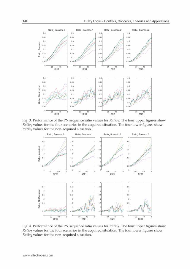
In Figures 3, 4, 5 and 6 a four-ratio comparison is made using the four simulation scenariosof Table 1. The four top subfigures plot the ratio values for the acquired situation; the fourbottom subfigures plot the ratio values for non-acquired situation. This evaluation is madefor each ratio (Ratio1, Ratio2, Ratio3 and Ratio1trac) and also for each scenario (scenario 0,scenario 1, scenario 2 and scenario 3) applying at each simulation a different SNR value inorder to perform a noise value study.
Figure 3 shows a clear difference between the values for Ratio1 in the case of acquisition andin the case of non-acquisition, especially for scenario 0. Scenario 1, scenario 2 and scenario3 values for acquisition are not so stable, and neither are the values for the non-acquisitionsituation. This is a behavior that will be repeated for the four ratios: the first scenario is theone that allows a better discrimination between acquisition and non acquisition in terms ofratios, it is the clearest to detect an acquisition. In the other three scenarios, due to the fact thatthey produce multipath, the values for the ratios are more ambiguous.
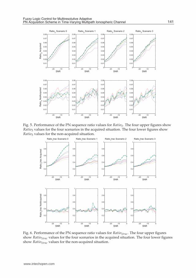
Figure 4 presents very good results for nearly all the PN sequences of the family. These figuresshow that Ratio2 can be used for performing an stable estimation of the decision to evaluate.Figure 5 shows a noisy Ratio3; but despite its unstable values for the non-acquired situation,values for Ratio3 in acquired scenarios 2 and 3, which are the worst results for the results tests,it exhibits a fairly distinct behavior in acquisition situation with respect to non-acquisitionsituation. Then Ratio3 information is valuable in the case of severe channel conditions. Finally,
139Fuzzy Logic Control for Multiresolutive Adaptive PN Acquisition Scheme in Time-Varying Multipath Ionospheric Channel
www.intechopen.com
10 Will-be-set-by-IN-TECH
-20 -10 00
0.05
0.1
0.15
0.2
0.25
0.3
0.35
0.4
Ratio1 Scenario 0
Ratio
1 A
cquired
SNR
-20 -10 00
0.05
0.1
0.15
0.2
0.25
0.3
0.35
0.4
Ratio
1 N
otA
cquired
SNR
-20 -10 00
0.05
0.1
0.15
0.2
0.25
0.3
0.35
0.4
Ratio1 Scenario 1
SNR
-20 -10 00
0.05
0.1
0.15
0.2
0.25
0.3
0.35
0.4
SNR
-20 -10 00
0.05
0.1
0.15
0.2
0.25
0.3
0.35
0.4
Ratio1 Scenario 2
SNR
-20 -10 00
0.05
0.1
0.15
0.2
0.25
0.3
0.35
0.4
SNR
-20 -10 00
0.05
0.1
0.15
0.2
0.25
0.3
0.35
0.4
Ratio1 Scenario 3
SNR
-20 -10 00
0.05
0.1
0.15
0.2
0.25
0.3
0.35
0.4
SNR
Fig. 3. Performance of the PN sequence ratio values for Ratio1. The four upper figures showRatio1 values for the four scenarios in the acquired situation. The four lower figures showRatio1 values for the non-acquired situation.
-20 -10 00
0.5
1
1.5
2
2.5
3
3.5
4
Ratio2 Scenario 0
Ratio
2 A
cquired
SNR
-20 -10 00
0.5
1
1.5
2
2.5
3
3.5
4
Ratio
2 N
otA
cquired
SNR
-20 -10 00
0.5
1
1.5
2
2.5
3
3.5
4
Ratio2 Scenario 1
SNR
-20 -10 00
0.5
1
1.5
2
2.5
3
3.5
4
SNR
-20 -10 00
0.5
1
1.5
2
2.5
3
3.5
4
Ratio2 Scenario 2
SNR
-20 -10 00
0.5
1
1.5
2
2.5
3
3.5
4
SNR
-20 -10 00
0.5
1
1.5
2
2.5
3
3.5
4
Ratio2 Scenario 3
SNR
-20 -10 00
0.5
1
1.5
2
2.5
3
3.5
4
SNR
Fig. 4. Performance of the PN sequence ratio values for Ratio2. The four upper figures showRatio2 values for the four scenarios in the acquired situation. The four lower figures showRatio2 values for the non-acquired situation.
140 Fuzzy Logic – Controls, Concepts, Theories and Applications
www.intechopen.com
Fuzzy Logic Control for Multiresolutive Adaptive PN Acquisition Scheme in Time-Varying Multipath Ionospheric Channel 11
-20 -10 00
0.01
0.02
0.03
0.04
0.05
0.06
0.07
0.08
Ratio3 Scenario 0
Ratio
3 A
cquired
SNR
-20 -10 00
0.01
0.02
0.03
0.04
0.05
0.06
0.07
0.08
Ratio
3 N
otA
cquired
SNR
-20 -10 00
0.01
0.02
0.03
0.04
0.05
0.06
0.07
0.08
Ratio3 Scenario 1
SNR
-20 -10 00
0.01
0.02
0.03
0.04
0.05
0.06
0.07
0.08
SNR
-20 -10 00
0.01
0.02
0.03
0.04
0.05
0.06
0.07
0.08
Ratio3 Scenario 2
SNR
-20 -10 00
0.01
0.02
0.03
0.04
0.05
0.06
0.07
0.08
SNR
-20 -10 00
0.01
0.02
0.03
0.04
0.05
0.06
0.07
0.08
Ratio3 Scenario 3
SNR
-20 -10 00
0.01
0.02
0.03
0.04
0.05
0.06
0.07
0.08
SNR
Fig. 5. Performance of the PN sequence ratio values for Ratio3. The four upper figures showRatio3 values for the four scenarios in the acquired situation. The four lower figures showRatio3 values for the non-acquired situation.
-20 -10 00
0.2
0.4
0.6
0.8
1
Ratio1trac Scenario 0
Ratio
1tr
ac A
cquired
SNR
-20 -10 00
0.2
0.4
0.6
0.8
1
Ratio
1tr
ac N
otA
cquired
SNR
-20 -10 00
0.2
0.4
0.6
0.8
1
Ratio1trac Scenario 1
SNR
-20 -10 00
0.2
0.4
0.6
0.8
1
SNR
-20 -10 00
0.2
0.4
0.6
0.8
1
Ratio1trac Scenario 2
SNR
-20 -10 00
0.2
0.4
0.6
0.8
1
SNR
-20 -10 00
0.2
0.4
0.6
0.8
1
Ratio1trac Scenario 3
SNR
-20 -10 00
0.2
0.4
0.6
0.8
1
SNR
Fig. 6. Performance of the PN sequence ratio values for Ratio1trac. The four upper figuresshow Ratio1trac values for the four scenarios in the acquired situation. The four lower figuresshow Ratio1trac values for the non-acquired situation.
141Fuzzy Logic Control for Multiresolutive Adaptive PN Acquisition Scheme in Time-Varying Multipath Ionospheric Channel
www.intechopen.com

12 Will-be-set-by-IN-TECH
Figure 6 plots the results for Ratio1trac; they are the best results given by the system in the fourscenarios and considering the four ratios. Nevertheless there is a drawback for Ratio1trac: thesystem must be acquired for this value to be reliable, otherwise just a noisy amount of outputvalues is shown.
This information is gathered, and one PN sequence is chosen for its good response to the fourratios in the four scenarios. This sequence is the dotted one in the four Figures (3, 4, 5 and 6).It has been chosen due to its minimization of the Euclidean distance with the best sequence ateach ratio evaluation.
4.1.2.3 Selected sequence
The selected PN sequence is not the best one for all the ratios and for all the scenarios. Itstands for the best global values, which means that is little noisy when comparing with theother sequences. In most of the results previously shown it reaches the best values (i.e. thevalues that better discriminates between acquisition and non acquisition).
Once chosen the preferred PN sequence, some statistics have to be computed over the ratiosobtained using this sequence. The ratios are computed again for a wider group of values ofSNR, and the results for the acquisition situation are shown in Figure 7. Over these resultsmedian, lower and upper quartiles are computed in order to fix some thresholds to definethe membership functions in the fuzzy input variables. Figure 8 shows the boxplots of thevalues for Ratio1 when acquired, and also performs the boxplots of the values for Ratio2 whenacquired. Figure 8 also gives the boxplots of the values for Ratio3 when acquired and thevalues for Ratio1trac when acquired.
In the last figure, the median values for the four ratios simulated in the four scenarios, and thequartiles for these groups of ratios are also shown. Especially the quartiles over the four ratioswhen the system is acquired can be considered the key to tune the membership functions forthe input variables.
4.1.2.4 Fuzzy membership functions
Finally, the input variables membership functions are defined. Four fuzzy sets have beendefined for each variable; two for the acquisition situation and two for the non-acquisitionsituation; only for Ratio1trac is defined with five fuzzy sets, three for acquisition situationand two for the non-acquisition situation. Only four sets have been considered, becausethe system needs to give the clear idea of whether the receiver is acquired or not, assumingdoubts. The four groups are named (from worse to best performance of the system) NotAcquired, Probably Not Acquired (∼ NoAcq), Probably Acquired (∼ Acq) and Acquired.The division between Not Acquired and Probably Not Acquired is the median value for thenon-acquired situation; and the same for Probably Acquired and Acquired, the threshold isthe median value for the acquired situation. The division between Probably Not Acquiredand Probably Acquired is held assuming that the maximum values for each are the low andhigh, respectively, quartiles for each of the ratios. All values are obtained with the mean valuefor the four ratios observed, and in case of doubt, always states the worst case. Some of thethresholds for the membership functions follow the worst case studio rule. Figures for themembership functions for Ratio1, Ratio2 and Ratio3 are shown in Figure 9, Figure 10 and 11,respectively. The only difference in the design is for membership functions of Ratio1trac; thisratio gives enough information to affirm that for some very high values (see statistics in Figure8), not only is acquired, but also is working with only one path, as shown in Figure 12.
142 Fuzzy Logic – Controls, Concepts, Theories and Applications
www.intechopen.com

Fuzzy Logic Control for Multiresolutive Adaptive PN Acquisition Scheme in Time-Varying Multipath Ionospheric Channel 13
-50 -40 -30 -20 -10 00
0.05
0.1
0.15
0.2
0.25
0.3
0.35
0.4
Ratio1 Acq
Ratio
1 V
alu
e
SNR-50 -40 -30 -20 -10 00
0.5
1
1.5
2
2.5
3
3.5
Ratio2 Acq
Ratio
2 V
alu
e
SNR
-50 -40 -30 -20 -10 00
0.01
0.02
0.03
0.04
0.05
0.06
0.07
0.08
Ratio3 Acq
Ratio
3 V
alu
e
SNR-50 -40 -30 -20 -10 00
0.2
0.4
0.6
0.8
1
Ratio1trac Acq
Ratio
1tr
ac V
alu
e
SNR
Scenario 0
Scenario 1
Scenario 2
Scenario 3
Scenario 0
Scenario 1
Scenario 2
Scenario 3
Scenario 0
Scenario 1
Scenario 2
Scenario 3
Scenario 0
Scenario 1
Scenario 2
Scenario 3
Fig. 7. Values for Ratio1, Ratio2, Ratio3 and Ratio1trac for an Acquired situation
4.2 Output variable and fuzzy sets
The output parameter is Acquisition, which gives a value in the range [0,1], being zero whenit is Not Acquired and one if it is Acquired. In between, two other fuzzy sets are defined:Probably Not Acquired and Probably Acquired.
The parameter Acquisition is used to give information to the detection stage about thereliability of the estimation. Notice that the multiresolutive structure gives an estimation ofthe acquisition point while the Acquisition value evaluates the probability of being acquired.
4.2.1 Output fuzzy sets
The critical values of the output variable Acquisition, around [0.4, 0.6] are divided into twofuzzy sets, the lower one corresponding to Probably Not Acquired and the higher onecorresponding to Probably Acquired. If the output variable obtains a critical value this isa result of non clear acquisition, so the decisional system does not have certainty about thereliability of the results. An additional period of time for acquisition is needed, and this is thegoal of the definition of these two fuzzy sets.
For values over 0.6 and under 0.4 the output variable Acquisition is clearly defined, being thefirst one clearly acquired, and the second one clearly not acquired.
143Fuzzy Logic Control for Multiresolutive Adaptive PN Acquisition Scheme in Time-Varying Multipath Ionospheric Channel
www.intechopen.com

14 Will-be-set-by-IN-TECH
1 2 3 40
0.05
0.1
0.15
0.2
0.25
0.3
0.35
RA
TIO
1
Sce0,Sce1,Sce2,Sce3
Sequence Acq
1 2 3 40
0.5
1
1.5
2
2.5
3
RA
TIO
2
Sce0,Sce1,Sce2,Sce3
Sequence Acq
1 2 3 40
0.01
0.02
0.03
0.04
0.05
0.06
0.07
RA
TIO
3
Sce0,Sce1,Sce2,Sce3
Sequence Acq
1 2 3 40
0.1
0.2
0.3
0.4
0.5
0.6
0.7
0.8
0.9
RA
TIO
1tr
ac
Sce0,Sce1,Sce2,Sce3
Sequence Acq
Fig. 8. Median and quartiles for Ratio1, Ratio2, Ratio3 and Ratio1trac for acquisition situation
4.3 If-then rules
If-then rules have been defined to obtain the best performance (in terms of reliability of theoutput variable Acquisition of the fuzzy estimator) along the full range of measured values foreach input parameter. Two examples of the dependence between input variables are shownin Figure 14, where dependence among Acquisition and Ratio1 and Ratio1trac, and also Ratio2
and Ratio3 are depicted.
The most critical estimation for the output variable Acquisition is the correspondence toProbably Not Acquired and to Probably Acquired; this means that the input parametershave no coherent values for Acquired or Not Acquired. To obtain a precise output value,the fuzzy estimator evaluates the degree of implication of each input parameter to the inputvariables membership functions and projects this implication to the fuzzy sets of the outputvariable Acquisition, in order to obtain its final value through defuzzyfication.
4.4 Decisional system feedback
Depending on the value of the output variable Acquisition, the multiresolutive acquisitionblock will perform in four different ways:
144 Fuzzy Logic – Controls, Concepts, Theories and Applications
www.intechopen.com

Fuzzy Logic Control for Multiresolutive Adaptive PN Acquisition Scheme in Time-Varying Multipath Ionospheric Channel 15
0 0.05 0.1 0.15 0.2 0.25 0.3 0.35 0.4
0
0.5
1
input variable "Ratio1"
NoAdq ~NoAdq ~Adq Adq
Fig. 9. Membership functions for input variable Ratio1
0 0.5 1 1.5 2 2.5 3 3.5
0
0.5
1
input variable "Ratio2"
NoAdq ~NoAdq Adq~Adq
Fig. 10. Membership functions for input variable Ratio2
0 0.01 0.02 0.03 0.04 0.05 0.06 0.07 0.08
0
0.5
1
input variable "Ratio3"
NoAdq ~NoAdq Adq~Adq
Fig. 11. Membership functions for input variable Ratio3
0 0.1 0.2 0.3 0.4 0.5 0.6 0.7 0.8 0.9 1
0
0.5
1
input variable "Ratio1trac"
NoAdq ~NoAdq~Adq Adq Adq-1path
Fig. 12. Membership functions for input variable Ratio1trac
145Fuzzy Logic Control for Multiresolutive Adaptive PN Acquisition Scheme in Time-Varying Multipath Ionospheric Channel
www.intechopen.com

16 Will-be-set-by-IN-TECH
0 0.1 0.2 0.3 0.4 0.5 0.6 0.7 0.8 0.9 1
0
0.5
1
output variable "adq"
NoAdq ~NoAdq ~Adq Adq
Fig. 13. Membership functions of Acquisition
(a) Acquisition as a function of Ratio1 and Ratio1trac (b) Acquisition as a function of Ratio2 and Ratio3
Fig. 14. Two examples of the variation of output variable Acquisition for all the whole rangeof values of the two ratios, taken by pairs.
• Acquired, it maintains the acquired position, saving computational load by stopping someof the adaptive filters used in the acquisition stage. This helps the structure to reduce itscomputational load. The ratios are computed only for the active filters, and each pauseperiod (fixed to a certain number of symbol periods) ends with a convergence of all thefilters, and a recalculation of all the ratios in order to prevent losing acquisition.
• Probably Acquired, it keeps the searching procedure to improve acquisition, and ofcourse, evaluations are maintained until the convergence is certain - if this is the case.
• Probably Not Acquired, move Ts4 the beginning of the data for the acquisition stage and
evaluate improvements; this pointer movement is used to prevent the system from failingin its purpose due to a bad initial pointer position. Not all the initial values are equallyconvenient for the multiresolutive structure; the optimum situation is when the acquisitionpoint is found in the middle of any of the four adaptive filters, and this approach helps theconvergence if the position is not the optimum, despite convergence is possible at any tapof the four LMS filters.
• Not Acquired, move Ts2 and evaluate to find changes. The move of Ts
2 is larger than inthe previous case because if the system is in an not acquired situation, it means that theacquisition is far to be detected, so the initial data for the acquisition stage can be found in
146 Fuzzy Logic – Controls, Concepts, Theories and Applications
www.intechopen.com

Fuzzy Logic Control for Multiresolutive Adaptive PN Acquisition Scheme in Time-Varying Multipath Ionospheric Channel 17
the worst place - the one that obtains the acquisition point far from the center of the LMSfilters -.
These four categories are chosen depending on the Acquisition output variable values. Thisfeedback improves the speed of convergence of the acquisition and reduces computationalload for the entire structure, by means of stopping the convergence of some of the adaptivefilters when convergence is assured.
5. Tests and results
In this Section the results of the performance of the designed fuzzy system are presented.First, an evaluation of the performance of the fuzzy control set designed is shown, evaluatingthe estimation reliability of the variable Acquisition against the true receiver state at everysimulation time. The second evaluation devoted to study the whole multiresolutive structureperformance. The results for the fuzzy multiresolutive structure are compared with thepreviously presented multiresolutive structure with a stability control (Morán et al., 2001).
Tests have been made using the four scenarios described in Section 4.1.2.1; in all simulationsthe same 128 chip PN sequence, obtained using an evolutionary strategy has been used (Alsinaet al., 2007a). In each test (for a certain SNR and a certain scenario) 600 symbols length datasequences have been used, and ten repetitions have been simulated using different channelinitialization; the presented results are the mean of all these evaluations.
5.1 Evaluation of the control system performance
In the evaluation of the control system performance three variables have been measured.The first is the % of correct acquisition estimations, comparing the Acquisition value withthe a posteriori measured probability of being acquired. The second is the % of incorrectacquisition estimations, but only for the optimistic ones; this means to evaluate when thefuzzy control system estimates the multiresolutive structure is acquired (assuming this iswhen Acquisition variable value is over 0.5), and the system real estimation of the acquisitionposition is incorrect. The last one is the % of incorrect acquisition estimation, but only forthe pessimistic ones; this means to evaluate when the fuzzy control system estimates themultiresolutive structure is not acquired (assuming this is when Acquisition variable is under0.5), and the system real estimation of the acquisition point is correct.
In Figure 15 these measurements are depicted. As shown in Figure 15.a, the % of correct fuzzyacquisition estimations perform good values, near 100%, except for the range of [-38,-35] dB,where all four scenarios present hit values of around 20%. This is due to a threshold SNRvalue, where the ratios make confusing evaluations due to the high level of noise. But this factis temporary, because when the SNR worsens, the ratios evaluated make the fuzzy systemconverge to the correct evaluation; however, in this case quite a lot of evaluations are for NotAcquired.
The error performance evaluations are shown in Figures 15.b and 15.c. These figures outstandthat most of the incorrect evaluations are for the system output indicating Not Acquired whenthe system is really Acquired. They also show that the optimistic incorrect estimations arereally better than those related to the pessimistic ones. These results are the main indicatorsof a good system robustness: the system remotely considers Acquisition wrongly, so theinformation detection process works only for the correct Acquisition situations. Although this
147Fuzzy Logic Control for Multiresolutive Adaptive PN Acquisition Scheme in Time-Varying Multipath Ionospheric Channel
www.intechopen.com

18 Will-be-set-by-IN-TECH
SNR
Scenario 3
Scenario 2
Scenario 1
Scenario 0
% Correct Fuzzy Evaluations
−50 −40 −30 −20 −10
−0.5
0
0.5
1
1.5
2
2.5
3
3.5 0
10
20
30
40
50
60
70
80
90
100
(a) % Correct Fuzzy evaluations
SNR
Scenario 3
Scenario 2
Scenario 1
Scenario 0
% Incorrect Fuzzy Evaluations − Optimistic Estimations
−50 −40 −30 −20 −10
−0.5
0
0.5
1
1.5
2
2.5
3
3.5 0
10
20
30
40
50
60
70
80
90
100
(b) % Incorrect Fuzzy evaluations - OptimisticErrors
SNR
Scenario 3
Scenario 2
Scenario 1
Scenario 0
% Incorrect Fuzzy Evaluations − Pessimistic Estimations
−50 −40 −30 −20 −10
−0.5
0
0.5
1
1.5
2
2.5
3
3.5 0
10
20
30
40
50
60
70
80
90
100
(c) % Incorrect Fuzzy evaluations - PessimisticErrors
Fig. 15. Performance of the Fuzzy Logic Control. Measurements about the correct andincorrect evaluations.
factor, it must be taken into account that some bad estimations (pessimistic ones) prevent thesystem from obtaining better information ratios in certain ranges of SNR [-38,-35] dB.
5.2 Evaluation of the Fuzzy Multiresolutive Acquisition vs. the Multiresolutive Structure
The evaluation of the Fuzzy Multiresolutive Acquisition structure vs. the MultiresolutiveStructure (Morán et al., 2001) is based on the comparison of the Acquisition estimationevaluated for both systems, obviously using the same channel conditions for the two systems.
5.2.1 The stability control for the Multiresolutive Structure
The Multiresolutive Structure presented by (Morán et al., 2001) works with a stability control.This control is based on the robustness of the filter convergence, using it as a premise for its
148 Fuzzy Logic – Controls, Concepts, Theories and Applications
www.intechopen.com

Fuzzy Logic Control for Multiresolutive Adaptive PN Acquisition Scheme in Time-Varying Multipath Ionospheric Channel 19
design. The stability control gives an output Acquired if the adaptive filter structure presentsthe same results for a certain number of times (in this case, three times). In the work of (Moránet al., 2001) it is shown that the probability of being acquired increases as the acquistionposition is more stable, and the stability control is based in this principle. The problems ofthe performance of this kind of stability control solution are lack of robustness in low SNRenvironments, interference and fading, and of course, multipath, because it cannot recognizea correct acquisition situation immediately; it was designed for enhance stability, so it keeps aNot Acquired output until the acquisition position is stable again.
SNR
Scenario 3
Scenario 2
Scenario 1
Scenario 0
% Correct Stability Evaluations
−50 −40 −30 −20 −10
−0.5
0
0.5
1
1.5
2
2.5
3
3.5 0
10
20
30
40
50
60
70
80
90
100
(a) % Correct Stability evaluations
SNR
Scenario 3
Scenario 2
Scenario 1
Scenario 0
% Incorrect Stability Evaluations − Optimistic Estimations
−50 −40 −30 −20 −10
−0.5
0
0.5
1
1.5
2
2.5
3
3.5 0
10
20
30
40
50
60
70
80
90
100
(b) % Incorrect Stability evaluations - OptimisticErrors
SNR
Scenario 3
Scenario 2
Scenario 1
Scenario 0
% Incorrect Stability Evaluations − Pessimistic Estimations
−50 −40 −30 −20 −10
−0.5
0
0.5
1
1.5
2
2.5
3
3.5 0
10
20
30
40
50
60
70
80
90
100
(c) % Incorrect Stability evaluations - PessimisticErrors
Fig. 16. Performance of the Stability Control. Measurements about the correct and incorrectevaluations.
This lack of robustness is improved with the design of the fuzzy control system, because itsestimation uses various instantaneous parameters, so reacquisition is faster; the fact of relyingon four different parameters ensures the robustness of the system, despite instantaneous nonconvergence situations for the LMS filters.
149Fuzzy Logic Control for Multiresolutive Adaptive PN Acquisition Scheme in Time-Varying Multipath Ionospheric Channel
www.intechopen.com

20 Will-be-set-by-IN-TECH
The results for the stability control solution are shown in Figures 16. Figure 16.a shows thecorrect performance of the stability control, and Figures 16.b and 16.c show the performancefor the incorrect stability evaluations, the first for the optimistic errors, and the second one forthe pessimistic. Figure 16.b depicts high optimistic error, which deal to the multiresolutivestructure to assume acquisition when it is not. This fact globally increases the BER at thereceiver in terms of confidence in the demodulation of the information.
5.2.2 Comparison results
In this Section a comparative analysis of the results of the fuzzy and the stability controls ismade. Numerical results for the four scenarios are computed, and the mean of these results istaken into account to compare the two control systems.
−50 −45 −40 −35 −30 −25 −20 −15 −10 −5 010
20
30
40
50
60
70
80
90
100
SNR
% C
orr
ect
Evalu
ations
% Correct Acquisition Evaluations − Fuzzy System
Mean correct values
Mean correct values Sce0
Mean correct values Sce1
Mean correct values Sce2
Mean correct values Sce3
(a) % Correct Fuzzy evaluations
−50 −45 −40 −35 −30 −25 −20 −15 −10 −5 010
20
30
40
50
60
70
80
90
100
SNR
% C
orr
ect
Evalu
ations
% Correct Acquistion Evaluations − Stability System
Mean correct values
Mean correct values Sce0
Mean correct values Sce1
Mean correct values Sce2
Mean correct values Sce3
(b) % Correct Stability evaluations
−50 −45 −40 −35 −30 −25 −20 −15 −10 −5 010
20
30
40
50
60
70
80
90
100% Correct Acquisition Evaluations − System Comparison
SNR
% C
orr
ect
Evalu
ations
Mean correct fuzzy evaluations
Mean correct stability evaluations
(c) Comparison of the correct evaluations for Fuzzyand Stability controls
Fig. 17. Comparison of the correct evaluations for both fuzzy and stability controls.
150 Fuzzy Logic – Controls, Concepts, Theories and Applications
www.intechopen.com

Fuzzy Logic Control for Multiresolutive Adaptive PN Acquisition Scheme in Time-Varying Multipath Ionospheric Channel 21
In Figure 17 an analysis of the performance for the correct estimation for both controls is done.In Figure 17.c the comparison for both is made in terms of %. The fuzzy control performsbetter for each SNR value except for the range [-38,-35] dB, where it performs worse, despitethe lowest SNR values back to get into a proper operation. It has to be noticed that the stabilitycontrol starts performing bad around -37 dB, and does not recover for worse SNR.
−50 −45 −40 −35 −30 −25 −20 −15 −10 −5 00
2
4
6
8
10
12
14
SNR
% O
ptim
istic E
valu
ations
% Incorrect Acquisition Evaluations − Fuzzy System
Mean incorrect values
Mean incorrect values Sce0
Mean incorrect values Sce1
Mean incorrect values Sce2
Mean incorrect values Sce3
(a) % Incorrect Optimistic Fuzzy Control systemevaluations
−50 −45 −40 −35 −30 −25 −20 −15 −10 −5 00
10
20
30
40
50
60
70
80
90
SNR
% O
ptim
istic E
valu
ations
% Incorrect Acquisition Evaluations − Stability System
Mean incorrect values
Mean incorrect values Sce0
Mean incorrect values Sce1
Mean incorrect values Sce2
Mean incorrect values Sce3
(b) % Incorrect Optimistic Stability Control systemevaluations
−50 −45 −40 −35 −30 −25 −20 −15 −10 −5 00
10
20
30
40
50
60
70
80% Incorrect Acquisition Evaluations − System Comparison
SNR
% O
ptim
istic E
valu
ations
Mean incorrect fuzzy evaluations
Mean incorrect stability evaluations
(c) Comparison of the incorrect Optimisticevaluations for Fuzzy and Stability Controls
Fig. 18. Comparison of the incorrect evaluations for both fuzzy and stability controls, in casethat the error is optimistic.
Figure 18 shows the incorrect optimistic evaluations for both fuzzy and stability controls.Optimistic error is very low for fuzzy control at any SNR (see Figure 18.a), and for stabilitycontrol is just the opposite: it has very high optimistic error, especially for lower SNR (seeFigure 18.b, and 18.c for a comparison between the two control systems). Then, the useof the stability control makes the multiresolutive structure be confident in the information
151Fuzzy Logic Control for Multiresolutive Adaptive PN Acquisition Scheme in Time-Varying Multipath Ionospheric Channel
www.intechopen.com

22 Will-be-set-by-IN-TECH
demodulation of the system when it is really not correctly acquired, and BER increases in thereceiver.
−50 −45 −40 −35 −30 −25 −20 −15 −10 −5 00
10
20
30
40
50
60
70
80
90
SNR
% P
essim
istic E
valu
ations
% Incorrect Acquisition Evaluations − Fuzzy System
Mean incorrect values
Mean incorrect values Sce0
Mean incorrect values Sce1
Mean incorrect values Sce2
Mean incorrect values Sce3
(a) % Incorrect Pessimistic Fuzzy Control systemevaluations
−50 −45 −40 −35 −30 −25 −20 −15 −10 −5 00
2
4
6
8
10
12
SNR%
Pessim
istic E
valu
ations
% Incorrect Acquisition Evaluations − Stability System
Mean incorrect values
Mean incorrect values Sce0
Mean incorrect values Sce1
Mean incorrect values Sce2
Mean incorrect values Sce3
(b) % Incorrect Pessimistic Stability Control systemevaluations
−50 −45 −40 −35 −30 −25 −20 −15 −10 −5 00
10
20
30
40
50
60% Incorrect Acquisition Evaluations − System Comparison
SNR
% P
essim
istic E
valu
ations
Mean incorrect fuzzy evaluations
Mean incorrect stability evaluations
(c) Comparison of the incorrect Pessimisticevaluations for Fuzzy and Stability Controls
Fig. 19. Comparison of the incorrect evaluations for both fuzzy and stability controls, in casethat the error is pessimistic.
In Figure 19 the pessimistic error for both controls is shown. In this case, Figure 19.adepicts a bad performance of the fuzzy control system for values ranging [-38,-35] dB, butits performance becomes better when SNR worsen. Figure 19.b outstands a more constantperformance for the stability control in the case of the pessimistic error.
5.3 Multiresolutive structure acquisition feedback
Finally, the possibilities of improving the performance of the multiresolutive structure (Moránet al., 2001) are shown through visualization of the output Acquisition behavior for the fuzzy
152 Fuzzy Logic – Controls, Concepts, Theories and Applications
www.intechopen.com

Fuzzy Logic Control for Multiresolutive Adaptive PN Acquisition Scheme in Time-Varying Multipath Ionospheric Channel 23
−50 −45 −40 −35 −30 −25 −20 −15 −10 −50.4
0.45
0.5
0.55
0.6
0.65
0.7
0.75
0.8
Mean value for Acquisition output
SNR
Mean v
alu
e f
or
Acquis
itio
n [
0,1
]
Scenario 0
Scenario 1
Scenario2
Scenario 3
Fig. 20. Mean output Acquisition values for the four scenarios
control system. The most important advantage of fuzzy logic vs. a stability control is that thequality of the acquisition can be measured; for high values of Acquisition, the performance ofthe system is better, for lower, the convergence is not guaranteed.
In Figure 20 the mean values of output variable Acquisition of the fuzzy control systemare shown (each value is computed for a specific scenario and SNR). This figure showsthe information that the fuzzy control gives to the decisional system of the multiresolutivestructure. At first, it is used to set the convergence (see the details in Section 4.4). If thevalue of Acquisition is higher than 0.75, the convergence is nearly guaranteed, and the systemdoes not need to run all the adaptive filters at each symbol time. If the value of Acquisitionis between 0.5 and 0.75, the system is Probably Acquired, but keeps searching to improveacquisition. But if Acquisition is between 0.25 and 0.75, the decisional system moves the data
for the acquisition stage by Ts4 , and evaluates the improvement of the convergence of the
filters. Finally, if the Acquisition value is lower than 0.25, the decisional system moves the data
for the acquisition stage by Ts2 and evaluates the convergence improvement. In the current
simulations, although some of the outputs for Acquisition were lower than 0.25, the values ofthe SNR tested mean Acquisition were evaluated over 0.4.
The second advantage of using continuous output values for the Acquisition variable isreducing computational load by stopping the search - filters LMS adaptation - duringacquisition state. Nearly 3
4 of the computational load of the LMS filters can be reduced incase of certain acquisition (shown through variable Acquisition value over 0.75) for SNR valuesranging [-20,0] dB approximately, while this is not possible to be done using a stability control.
5.4 Summary
In this section, the evaluation results have been shown for the performance of the fuzzy logiccontroller in the multiresolutive acquisition structure. The fuzzy logic control system showsgood performance even for low SNR, except for the values in the range [-38,-35]dB; in thisrange the estimation error increases due to pessimistic errors. In comparison with the stabilitycontrol, the global behavior is improved because the fuzzy control has better results above
153Fuzzy Logic Control for Multiresolutive Adaptive PN Acquisition Scheme in Time-Varying Multipath Ionospheric Channel
www.intechopen.com

24 Will-be-set-by-IN-TECH
the critical margin of [-38,-35]dB, and it behaves really well for lower SNR. Another clearadvantage of the fuzzy control against the stability control is the wider range of possibleoutput values. This fact allows the multiresolutive structure to decrease its computationalload when the system is clearly acquired, and also to change the acquisition pointer in caseof a far acquisition estimated point; this information enhances the receiver performance, notonly in terms of reliability, but also in terms of computational load.
6. Conclusions
In this chapter a novel fuzzy control system for a multiresolutive acquisition structure (Moránet al., 2001) is detailed. It can be concluded that the four computed ratios used as inputvalues for the control system (Ratio1, Ratio2, Ratio3 and Ratio1trac) perform coherently withthe results of the multiresolutive structure. Therefore, decisions can be made attending to theirvalues. It can be stated that these ratios stand out for the performance of the whole system, andtheir values for the four simulated scenarios are found in the same range of values. Therefore,we conclude that they might be useful to describe and optimize the system performance.
The fuzzy logic control gives a more precise output acquisition variable allowing the systemto conclude whether it is correctly acquired, probably acquired, probably not acquired, andnot acquired; then, the control logic can optimize the computational load of the structuredepending on these values. If the system is correctly acquired (depending on the value forAcquisition), the decisional system reduces the global computational load by stopping theconvergence of some LMS adaptive filters (despite the detailed computational load study isnot included in this chapter). So, not only the acquisition estimation is improved, but alsothe global performance of the structure is optimized. The only SNR range where the fuzzycontrol system performance can significantly be improved is around [-40,-35] dB, where thisperformance is poor. It is also important to note that the correct estimation of the acquisitionfor very low SNR values helps the system in terms of confidence about the demodulatedinformation; in case of the stability control, for values worse than -36 dB the informationdemodulated is notoriously unreliable; and for fuzzy control, Acquisition continuous valuegives enough information to know whether the system is out of the correct acquistion area,and hence the system not being confident on the information results. Future research isfocused in improving the performance of the fuzzy control in the multiresolutive structure,especially at specific levels of SNR where the results behavior is pessimistic, in order toincrease the reliability of the system estimation.
The results shown in this chapter stand out for the application of fuzzy control systemsto other acquisition schemes found in the literature, and allow us to state that our workrepresents an interesting proposal to the future research in this field; the LMS adaptive schemepresented by (El-Tarhuni & Sheikh, 1996), lately improved by (Han et al., 2006), and alsothe adaptive system for ocean acquisition transmission presented by (Stojanovic & Freitag,2003). We think that the knowledge of the channel characteristics and the behavior of theLMS filter convergence would be the first data to be taken into account to the design afuzzy control system conceived with the aim of improving the stability and the robustnessof any acquisition receiver for a DS-SS communications system. This aspect is highlightedhere, because control systems designed to operate within LMS-based adaptive acquisitionschemes found in the literature do not consider other information rather than the stability ofthe acquisition estimation.
154 Fuzzy Logic – Controls, Concepts, Theories and Applications
www.intechopen.com

Fuzzy Logic Control for Multiresolutive Adaptive PN Acquisition Scheme in Time-Varying Multipath Ionospheric Channel 25
7. Acknowledgments
This work has been funded by the Spanish Government under the projectsREN2003-08376-C02-02, CGL2006-12437-C02-01/ANT, CTM2008-03236-E/ANT,CTM2009-13843-C02-02 and CTM2010-21312-C03-03. La Salle thanks the Comissionatper a Universitats i Recerca del DIUE de la Generalitat de Catalunya for their support under thegrant 2009SGR459. We must also acknowledge the support of the scientists of the Observatoryde l’Ebre throughout the research work.
8. References
Akhter, N., Ferdouse, L., Jaigirdar, F. & Nipa, T. (2010). A Performance Analysis of LMS, RLSand Lattice based Algorithms as Applied to the Area of Linear Prediction, Journal ofGlobal Research in Computer Science 1: 49–53.
Alsina, R., Bernadó, E. & Morán, J. (2005b). Evolution Strategies for DS-CDMA PseudonoiseSequence Design, Frontiers in Artificial Intelligence and Applications - ArtificialIntelligence Research and Development 131: 189 – 196. IOS Press.
Alsina, R. M., Bergadà, P., Socoró, J. C. & Deumal, M. (2009a). Multiresolutive AcquisitionTechnique for DS-SS Long-Haul HF Data Link, Proceedings of the 11th Ionospheric RadioSystems and Techniques (IRST), IET, Edimburgh (Regne Unit).
Alsina, R. M., Formiga, L., Socoró, J. C. & Bernadó, E. (2007a). Multiobjective EvolutionStrategies for DS-CDMA Pseudonoise Sequence Design in a MultiresolutiveAcquisition, Frontiers in Artificial Intelligence and Applications - Artificial IntelligenceResearch and Development 163: 384 – 391. IOS Press.
Alsina, R. M., Mateo, C., Socoró, J. C. & Deumal, M. (2008). Neural Network AcquistitionEstimator for Multiresolutive Adaptive PN Acquisition Scheme in Multiuser NonSelective Fast SNR Variation Environments, 8th International Conference on HybridIntelligent Systems (HIS), Barcelona (Espanya).
Alsina, R., Mateo, C. & Socoró, J. (2007b). Multiresolutive Adaptive PN Acquisition Schemewith a Fuzzy Logic Estimator in Non Selective Fast SNR Variation Environments,Lecture Notes in Computer Science - Springer Verlag 4507: 367 – 374. International Work-conference on Artificial Neural Networks (IWANN).
Alsina, R., Mateo, C. & Socoró, J. (2009b). Artificial Intelligence Enciclopaedia, IGI Global, (EUA),chapter ’F’: Fuzzy Logic Estimator for Variant SNR Environments, pp. 719–728.
Alsina, R., Morán, J. & Socoró, J. (2005a). Sequential PN Acquisition Scheme Based on a FuzzyLogic Controller, Lecture Notes in Computer Science - Springer Verlag 3512: 1238 – 1245.International Work-conference on Artificial Neural Networks (IWANN).
Bas, J. & Perez-Neira, A. (2003). A Fuzzy Logic System for Interference Rejection in CodeDivision Multiple Access, IEEE International Conference on Fuzzy Systems 2: 996–1001.
Bergadà, P., Deumal, M., Alsina, R. & Pijoan, J. (2009). Time Interleaving Study for an OFDMLong-Haul HF Radio Link, in T. IET (ed.), Proceedings of the 11th Ionospheric RadioSystems and Techniques, Edimburgh (UK).
Daffara, F. (1995). A Fuzzy Rule Based Phase Error Detector, Proceedings of URSI InternationalSymposium on Signals, Systems, and Electronics.
Deumal, M., Vilella, C., Socoró, J., Alsina, R. & Pijoan, J. (2006). A DS-SS SignalingBased System Proposal for Low SNR HF Digital Communications, IEEE InternationalConference on Ionospheric Radio Systems and Techniques, IEEE, London, UK.
155Fuzzy Logic Control for Multiresolutive Adaptive PN Acquisition Scheme in Time-Varying Multipath Ionospheric Channel
www.intechopen.com

26 Will-be-set-by-IN-TECH
Drake, J. & Prasad, N. (1999). Current Trends Towards Using Soft Computing Approaches toPhase Shyncrhonization in Communications Systems, IEEE 42nd Midwest Symposiumon Circuits and Systems.
El-Tarhuni, M. & Sheikh, A. (1996). MSE Tracking Performance of DS-SS Code TrackingScheme Using an Adaptive Filter, Electronic Letters 32: 1543–1545.
Gad, A. & Farouq, M. (2001). Applications of Fuzzy Logic in Engineering Problems,Proceedings of the Annual Conference of IEEE Industrial Electronics Society.
Glisic, S. G. (1991). Automatic Decision Threshold Level Control in Direct Sequence SpreadSpectrum Systems, IEEE Transactions on Communications 39(2): 519–527.
Glisic, S. & Vucetic, B. (1997). Spread Spectrum CDMA Systems for Wireless Communications,Artech House Publishers, United States of America.
Han, M., Yu, T., Kang, C. & Hong, D. (2006). A New Adaptive Code-AcquisitionAlgorithm Using Parallel Subfilter Structure, IEEE Transactions on Vehicular Technology55(6): 1790–1796.
Haykin, S. (1996). Adaptive Filter Theory, Prentice Hall International, United States of America.Morán, J., Socoró, J., Jové, X., Pijoan, J. & Tarrés, F. (2001). Multiresolution Adaptive Structure
for acquisition in DS-SS receivers, International Conference on Acoustics, Speech andSignal Processing .
Perez-Neira, A. & Lagunas, M. (1996). High Performance DOA Trackers Derived from ParallelLow Resolution Detectors, IEEE Workshop on SSAP.
Perez-Neira, A., Lagunas, M. & Bas, J. (1997). Fuzzy Logic for Robust Detection in WirelessCommunications, Proceedings of the 8th IEEE International Symposium on Personal,Indoor and Mobile Radio Communications.
Peterson, R., Ziemer, R. & Borth, D. (1995). Introduction to Spread Spectrum Communications,Prentice Hall, United States of America.
Proakis, J. (1995). Digital Communications, McGraw-Hill, Singapore.Sklar, B. (1988). Digital Communications, Fundamentals and Applications, Prentice Hall
International, United States of America.Stojanovic, M. & Freitag, L. (2003). Acquisition of Direct Sequence Spread Spectrum Acoustic
Communication Signals, Oceans 1: 279 – 286.Vilella, C., Miralles, D., Altadill, D., Acosta, F., Sole, J., Torta, J. M. & Pijoan, J. (2009). Vertical
and Oblique Ionospheric Soundings over a Very Long Multihop HF Radio Link fromPolar to Midlatitudes: Results and Relationships, Radio Science 44.
Vilella, C., Miralles, D. & Pijoan, J. (2008). An Antarctica-to-Spain HF ionospheric radio link:Sounding results, Radio Sci. 43(doi:10.1029/2007RS003812).
Zadeh, L. (1965). Fuzzy Sets, IEEE Transactions on Information and Control 8: 338–353.Zadeh, L. (1988). Fuzzy Logic, Computer 21(4): 83–92.
156 Fuzzy Logic – Controls, Concepts, Theories and Applications
www.intechopen.com

Fuzzy Logic - Controls, Concepts, Theories and ApplicationsEdited by Prof. Elmer Dadios
ISBN 978-953-51-0396-7Hard cover, 428 pagesPublisher InTechPublished online 28, March, 2012Published in print edition March, 2012
InTech EuropeUniversity Campus STeP Ri Slavka Krautzeka 83/A 51000 Rijeka, Croatia Phone: +385 (51) 770 447 Fax: +385 (51) 686 166www.intechopen.com
InTech ChinaUnit 405, Office Block, Hotel Equatorial Shanghai No.65, Yan An Road (West), Shanghai, 200040, China
Phone: +86-21-62489820 Fax: +86-21-62489821
This book introduces new concepts and theories of Fuzzy Logic Control for the application and development ofrobotics and intelligent machines. The book consists of nineteen chapters categorized into 1) Robotics andElectrical Machines 2) Intelligent Control Systems with various applications, and 3) New Fuzzy Logic Conceptsand Theories. The intended readers of this book are engineers, researchers, and graduate students interestedin fuzzy logic control systems.
How to referenceIn order to correctly reference this scholarly work, feel free to copy and paste the following:
Rosa Maria Alsina-Pages, Claudia Mateo Segura, Joan Claudi Socoró Carrié and Pau Bergada (2012). FuzzyLogic Control for Multiresolutive Adaptive PN Acquisition Scheme in Time-Varying Multipath IonosphericChannel, Fuzzy Logic - Controls, Concepts, Theories and Applications, Prof. Elmer Dadios (Ed.), ISBN: 978-953-51-0396-7, InTech, Available from: http://www.intechopen.com/books/fuzzy-logic-controls-concepts-theories-and-applications/fuzzy-logic-control-for-multiresolutive-adaptive-pn-acquisition-scheme-in-time-varying-multipath-ion