fuzzy logic based automation and control simulation of ... (part-2)/c0281935.pdf · fuzzy logic...
TRANSCRIPT
IOSR Journal of Engineering (IOSRJEN)
ISSN: 2250-3021 Volume 2, Issue 8 (August 2012), PP 19-35 www.iosrjen.org
www.iosrjen.org 19 | P a g e
Fuzzy logic based automation and control simulation of Sulfuric
acid manufacturing process: A case study
Dinesh Singh Rana Department of Instrumentation, Kurukshetra University, Kurukshetra
Abstract: - Control of Chemical Plant is important because it further comprises of small plants ranging from
water control up to the chemical composition control. Most of the chemical processes are non linear and non
stationary. Also the process dynamics of these processes is not well understood due to some unknown
disturbances. So fuzzy logic control is best suited for such types of processes where process dynamics is
complex. In present paper, a Fuzzy logic system has been purposed that is particularly suited for Sulfuric acid
plant. The system design starts from identification of inputs, Outputs and choosing the membership function for
each condition from normal operation up to emergency operation of sulfuric plant. A complete automation and
control of sulfuric acid production process has been implemented which show consistent results.
Keywords: - Fuzzification, Inference Engine , defuzzification, process dynamics, membership functions
I. Introduction Most of chemical reaction processes are nonlinear in nature. Moreover its modeling is also complicated.
In chemical industry, the processes are in general complex, with delays, non-linearity; it is not always possible to
control them with classical regulators [1]. The major disadvantage in fuzzy control is lacking analytical design
technique i.e. determination of parameters of Membership functions [2-3]. Basic knowledge of pure physics and
chemistry is needed with advanced engineering for the development of Instrumentation system to chemical
process control. Conventional and advanced controllers (like PID & MRAC respectively) need most accurate
modeling; in addition simulation has also some defects in virtual implementation and testing. Fuzzy controllers
have a non-linear behavior that makes them a useful tool for the chemistry industry [4].
The application of the Fuzzy Set Theory to a wide range of control applications has made possible the
establishment of intelligent control in these areas [5]. A relationship is to be developed between the inputs and
outputs with the help of the fuzzy logic controller [6]. Sulfuric Acid production is also one of the nonlinear and
in addition exothermic one. Here two parameters, concentration and temperature plays vital role and shows nonlinear behavior while producing sulfuric acid. For accurate and safe operation one must have a very good
mathematical model of both plants as well process. It is difficult to get good control and accuracy due to less
reliability of mathematical model or errors in the model. So instead of conventional or advanced controller which
totally depends on the mathematical model, fuzzy logic control strategy has been selected as an option. This
scheme of control will evaluate certainty within uncertainty and handling the parameters within range to control
the entire process continuously though fluctuations occurs [7-8]. Fuzzy control provides effective solutions for
nonlinear and partially unknown processes, mainly because of its ability to combine information from different
sources [9]. The fuzzy knowledge base consists of a set of physically interpretable if-/then rules providing
physical insight into the process [10]. Therefore the process industries require more reliable, accurate, robust,
efficient and flexible control systems for the operation of process plant.
II. Process dynamics: Production of sulfur dioxide The flow diagram of sulfuric acid manufacturing process is shown in figure 1. Solid Sulfur is melted by
steam coils at 140°C in brick lined tanks. The molten sulfur is filtered to remove any impurities (usually iron or
organic compounds). The molten sulfur is pumped to the burner where it is burnt in an excess of dry air. The gas
exiting the burner is maintained at 8-9%v/v sulfur dioxide and approximately 830°C due to the heat produced by
the exothermic reaction [3]. This reaction is described by the equation[3]:
S + O2 → SO2 (1) ΔH = -300 kJ mol-1
The sulfur dioxide/air gas mixture is then passed through the hot gas filter situated besides the air burner,
where any ash contamination is removed. The sulfur dioxide is converted to sulfur trioxide by reacting with oxygen over a catalyst. This reaction is described by the equation:
SO2 + ½O2→SO3 (2) ΔH = -100 kJ mol-1
This reaction occurs in the converter in which a four-stage reaction vessel, with each stage consisting of
a solid catalyst bed through which the gas is passed. The catalyst used is vanadium pent oxide (V2O5) and
potassium sulphate dispersed on a silica base; this forms a porous support, giving a large surface area for reaction.
It is believed that the V2O5 increases the rate of the overall chemical reaction by oxidizing the SO2 to SO3 and

Fuzzy logic based automation and control simulation of Sulfuric acid manufacturing process: A case
www.iosrjen.org 20 | P a g e
being re-oxidized itself by the oxygen in the gas stream. This reaction is exothermic and its equilibrium constant
decreases with increasing temperature. Figure 1 shows the percentage conversion of SO2 to SO3 that would be
reached at an SO2 concentration of 8% v/v and a range of gas temperatures. However, the reaction rate is also
temperature dependent, so that if the temperature becomes too low the equilibrium point will not be reached. In
practice, the gas temperature must be maintained between 400 - 500°C to maintain a high reaction rate and also
high conversion equilibrium [3]. As the reaction is exothermic, heat is generated across each of the catalyst beds.
This heat must be removed between each stage to maintain the optimum reaction temperature into the following stage. The greatest degree of cooling is required between the first and second stages. Cooling after the second and
third stages is by injection of dried air. The gas is passed to the absorption tower, a packed tower where SO3 is
absorbed into a counter-current flow of 98 - 99% sulfuric acid. The overall reaction can be described by the
following equation, where sulfur trioxide reacts with the free water to produce sulfuric acid:
Figure 1: Flow Diagram of Sulfuric acid manufacturing process
SO3 + H2O → H2SO4 (3) ΔH = -200 kJ mol-1
The circulating sulfuric acid must be maintained at about 98% concentration and 70° C to maximize the
absorption efficiency. The acid strength is important because the vapor pressure of sulfur trioxide above sulfuric
acid is at a minimum at an acid strength of 98% which is depicted in figure 3. At higher concentrations the
increased vapor pressure is caused by SO3 and at lower concentrations the water vapor pressure increases sharply
and the resultant acid mist is not readily re-absorbed and escapes to the atmosphere.
The sulfuric acid is circulated at such a rate that there is only a very small increase in concentration
through the absorber tower. Dilution water is added to the circulating acid tank and also as atmospheric water absorbed in the drying tower. A stream of sulfuric acid is continuously bled off and cooled through a plate heat
exchanger before being passed into the storage tanks. The overall conversion from sulfur to sulfuric acid is
greater than 98.5%. The plant operates under an air discharge permit which controls emissions of sulfur dioxide
and total acidity. Traditionally mild steel has been used as the primary material of construction for process
equipment containing 98% sulfuric acid. The corrosion rate is reasonably low, except at the air/liquid interface
where atmospheric moisture encourages corrosion. Raw sulfur is melted and cleaned then it is burnt in the
presence of air, here moister contamination prevention is the important criteria. Second is the production of SO2
gas is also important criteria because volume flow and temperature of SO2 gas will decide how the boiler would
work, another important point over here is reactor’s 1st and 2nd stage temperature which is to be maintained

Fuzzy logic based automation and control simulation of Sulfuric acid manufacturing process: A case
www.iosrjen.org 21 | P a g e
according to figure shown above. The reactor temperature is important because according to temperature
deviation in the all four stage the rate of conversion of sulfuric dioxide to trioxide also get affected. In 3rd step of
the process plant the concentration plays a vital role for both sulfuric acids as well sulfur trioxide.
III. Fuzzy logic control Fuzzy logic can be viewed as an extension of multi valued logic system. In two valued logic system a
proposition is either true or false. In multi valued logic system a proposition may be true or false or have an
intermediate truth value which may be an element of infinite truth valued set. In fuzzy logic, the truth values
may range over the fuzzy subset. The fuzzy logic controller is designed to deal with the situations where
available source of information are inaccurate, subjectively interpreted or uncertain. The main constitutes of
fuzzy controller are Fuzzification, Knowledge base, Rule base, Inference strategy and defuzzification. Figure
4(a) shows the Block diagram of Fuzzy controller. Fuzzification is the process of converting the inputs variable
values (sensor signal values) into linguistic variable values or membership function in fuzzy logic sets (fuzzy
values). Rule-base of fuzzy logic breaks the control problem down into a series of IF X AND Y THEN Z rules
that define the desired system output response for given system input conditions . The number and complexity
of rules depends on the number of input parameters that are to be processed and the number of fuzzy variables associated with each parameter[7-8]. Create fuzzy logic membership functions that define the meaning (values)
of input/output terms used in the rules. Defuzzification is the process in which output linguistic variable value
(fuzzy variable value) is translated into crisp value (real value).
Figure 4(a): Block diagram of Fuzzy Controller
FUZZY TECH SOFTWARE 5.5 is used for the automatic control of sulfuric acid manufacturing
process. It contains all the editors, analyzers and tools to design a complete fuzzy logic system. It supports
various fuzzy logic inference methods and algorithms. The first step in a fuzzy logic system design is the
definition of the system structure. Here, we define the inputs & outputs of the fuzzy logic system and how they
interact. As shown in figure 4(b) the small blocks on the left side are the input interfaces. The input interfaces
also contain the fuzzification of the input values. The icon on the left indicates the employed fuzzification
method. The small blocks on the right side are the output interfaces that contain the defuzzification method. The larger block in the middle of the screen is the rule blocks. The rule blocks each contain an independent set of
fuzzy logic rules. The left column shows the variables used in the precondition of fuzzy rules. The right column
shows the variables used for the conclusion of fuzzy rules. The upper box displays the Condition Aggregation
Operator. The lower box shows the Result Aggregation Operator.
Figure 4(b): Text block explaining object of Fuzzy control system

Fuzzy logic based automation and control simulation of Sulfuric acid manufacturing process: A case
www.iosrjen.org 22 | P a g e
IV. Process Description for development of fuzzy control strategy: The P&ID diagram of Sulfuric acid manufacturing process has been developed and presented in figure
5. The abbrevation of various instrument and physical variables used in automation and control of sulfuric acid
plant has been presented in Table 1. Sulfur is feeded to the sulfur melting tank. Here it is melted with fix temperature steam. Tank’s level and temperature would decides whether to feed and how much to feed solid
sulfur and steam to the tank. The melted sulfur is pumped to the next tank called dirty sulfur tank. The solid
sulfur, which is melted & converted to the liquid state, having some contamination needed to be removed. So
this dirty sulfur is pumped & passed to the sulfur filter and then to the clean sulfur tank. The MTBM (Mean
Time between Maintenance) means the sulfur filter chocking condition would be counted in advance. The
pressure switch of sulfur filter will alert the control system when to replace the filter & between this times
production would not be paused though earlier stage pumping would stop, this is due to independency of level
parameter of clean sulfur tank.
Step 1: The clean sulfur is pumped to the air burner with respect to clean sulfur tank level, air burner pressure, air
burner temperature & dryer humidity conditions, synchronously air from the dryer faded to the air burner
according to sulfur flow to the burner, pressure & temperature of air burner & dryer humidity conditions. Dryer is feeded with air coming through filter & dryer volume is controlled through a pressure switch. Here when dryer
humidity crosses its limit, this pause the whole SO2 production process & further so on. But most of MTBM for
changing dryer beds are so set that it wont affects the production process. On the basis of volume flow,
temperature of produced Sulfuric Dioxide gas, temperature of boiler & pressure of boiler, the feed control valve
of Sulfuric Dioxide gas to the boiler is controlled. The boiler is waste heat boiler which converts the waste heat
produced due to exothermic reaction to the usable steam. The feed water to the waste heat boiler is controlled by
the feed water control valve which is dependent of parameters are level, pressure & temperature of the boiler. In
addition temperature of 3rd & 4th stage of four stage converter/reactor & humidity condition of dryer decides the
air feeding to those particular stages of converter/reactor.
Step: 2 Sulfuric dioxide gas is converted into sulfuric trioxide gas inside the converter/reactor with the help of vanadium pant oxide catalyst bed. Three parameters, temperature of 1st stage of converter/reactor, temperature
and flow of the Sulfuric Dioxide gas coming from the boiler decides feed control to the converter/reactor
through the control valve for reactor sulfuric dioxide gas feed control. Cooling of Sulfuric Trioxide gas is
needed after passing through 1st stage of reactor because having reaction with vanadium pent oxide (V2O5)
sulfuric dioxide’s temperature would again rise due to this reaction is also be an exothermic one. The coolant
feeded to the heat exchanger for the cooling of this sulfuric trioxide gas is controlled with the coolant flow
control valve which is operated on the conditions of the two temperature parameters; these are temperature of 1st
and 2nd stage of reactor.
Step3: Concentration of sulfuric trioxide gas coming to two stage absorber, concentration of sulfuric acid, vapor
pressure inside 1st stage of absorber & concentration of sulfuric trioxide gas venting from absorber would decide
volume flow of sulfuric trioxide gas entering to a two stage absorber through sulfuric trioxide flow control valve. The unabsorbed sulfuric trioxide gas having less concentration is to be vented and gas having higher
concentration is to be recycled, this is done by stopping the feed of sulfuric trioxide coming from reactor & by
stopping vent from absorber with opening of recycle valve. This is done with the help of one three way valve and
one recycle valve, one angle and one linear on off type. The operation of these valves would be decided by
vapour pressure inside the absorber, concentration of sulfuric acid and concentration of sulfuric trioxide gas being
vented from the absorber. The feed rate of dilution water to the high concentration sulfuric acid being stored in
the acid circulation tank is decided by level of the acid circulation tank, concentration of sulfuric acid inside the
acid circulation tank and flow of high concentration sulfuric acid towards the acid circulation tank. The
circulation of lower concentration sulfuric acid is done with the help of circulation pump of which’s speed is
controlled through level of the acid circulation tank, concentration of sulfuric acid inside that tank and
concentration of sulfuric acid of 2nd stage of absorber. The vapor pressure above the sulfuric acid inside the acid circulation tank is controlled through two valves. One valve feed additional air pressure when vapour pressure is
lower than desired and one valve vents the vapour by opening when pressure is higher than desired. The pumping
of sulfuric acid of desired concentration is pumped to the acid storage tank in accordance to level of both acid
circulation and storage tanks and pumping condition of acid circulation pump. And the final output is taken on the
basis of level of storage tank with storage tank pump in respect.

Fuzzy logic based automation and control simulation of Sulfuric acid manufacturing process: A case
www.iosrjen.org 23 | P a g e
Figure 5: Process Equipment and Instrumentation lay out of the process

Fuzzy logic based automation and control simulation of Sulfuric acid manufacturing process: A case
www.iosrjen.org 24 | P a g e
4.1. Defining Control Loops and Application of Fuzzy Logic for step1
The complete fuzzy logic based control system for step 1 excluding the controller for control valves V3 and V4 has been illustrated in figure 6. and the summary of rules for all steps are illustrated in table 2.
Figure 6: Fuzzy Logic control for Step-1 excluding the control of valves V3 and V4
Fuzzy logic based automation and control simulation of Sulfuric acid manufacturing process: A case
www.iosrjen.org 25 | P a g e
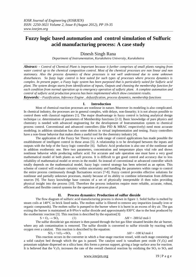
(i) HP hoper controls the quantity of solid sulfur being fed into the SMT. Control parameters for SMT
are level L1 and temperature T0. Here V1 is the control valve which feeds fix temperature steam to the tank for
melting the solid sulfur. So we can define the control Loops over here. The membership function of each are
defined in figures 7-10. IF L1 & T0 THEN HP; IF L1 & T0 & HP THEN V1
Figure 7: Member ship function of L1 Figure 8: Member ship function of T0
Figure 9: Member ship function of HP Figure109: membership function for V1
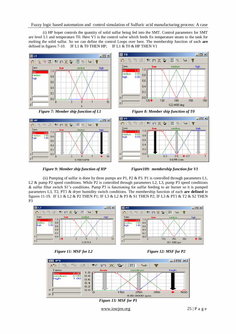
(ii) Pumping of sulfur is done by three pumps are P1, P2 & P3. P1 is controlled through parameters L1, L2 & pump P2 speed conditions. While P2 is controlled through parameters L2, L3, pump P3 speed conditions
& sulfur filter switch S1’s conditions. Pump P3 is functioning for sulfur feeding to air burner so it is pumped
parameters L3, T2, PT1 & dryer humidity switch conditions. The membership function of each are defined in
figures 11-19. IF L1 & L2 & P2 THEN P1; IF L3 & L2 & P3 & S1 THEN P2; IF L3 & PT1 & T2 & S2 THEN
P3
Figure 11: MSF for L2 Figure 12: MSF for P2
Figure 13: MSF for P1

Fuzzy logic based automation and control simulation of Sulfuric acid manufacturing process: A case
www.iosrjen.org 26 | P a g e
Figure 14: MSF for S1 Figure 15: MSF for L3
Figure 16: MSF for P3 Figure 17: MSF for S2
Figure 18: MSF for T2 Figure 19: MSF for PT1
(iii) Blower B1 feeds air to dryer and dryer feeds air to Burner via Air to Burner valve V2. B1 depends
on humidity S2, Air filter pressure S4 and Dryer pressure S3. While V2 will be operated with sulfur flow F2,
Air Burner Pressure PT1 & Temperature T2 and dryer humidity switch S2. The membership function of each
are defined in figures 20-28. IF PT1 & F2 & T2 & S2 THEN V2; IF S4 & S3 & S2 THEN B1; IF S2 & T8
THEN V7; IF S2 & T9 THEN V8
Figure 20: MSF for F2 Figure 21: MSF for V2

Fuzzy logic based automation and control simulation of Sulfuric acid manufacturing process: A case
www.iosrjen.org 27 | P a g e
Figure 22: MSF for S3 Figure 23: MSF for S4
Figure 24: MSF for B1
(iv) 3rd
Stage temprature cooling vlave (V7) control of 4SCR
Figure 25: MSF for T8 Figure 26:MSF for V7
Figure 27: MSF for T9 Figure 28: MSF for V8
4.1.1. Fuzzy Logic Design for Step-1 for controlling control valve V3 & V4
(i) Sulfuric Dioxide gas coming from AB will be controlled by its flow F3 & temperature T3 with
Boiler’s Pressure PT2 & temperature T4. The membership function of each are defined in figures 29-33.
IF F3 & PT2 & T3 & T4 THEN V3

Fuzzy logic based automation and control simulation of Sulfuric acid manufacturing process: A case
www.iosrjen.org 28 | P a g e
Figure 29: MSF for F3 Figure 30: MSF for PT2
Figure 31: MSF for T3 Figure 32: MSF for T4
Figure 33: MSF for V3
(ii) Feed water for Waste Heat Boiler is controlled through V4 valve with L4, PT2 & T4. The
membership function of each are defined in figures 34-35. IF L4 & PT2 & T4 THEN V4
Figure 34: MSF for L4 Figure 35: MSF for V4
The complete Fuzzy Logic Control for Step 1for control of valves V3 & V4 has been illustrated in figure 36.

Fuzzy logic based automation and control simulation of Sulfuric acid manufacturing process: A case
www.iosrjen.org 29 | P a g e
Figure 36: Fuzzy Logic Control for Step 1for control of valves V3 & V4
4.2. Defining Control Loops and Application of Fuzzy Logic for step2
The complete fuzzy logic based control system for step 2 has been illustrated in figure 37 and the summary of
rules for all steps are illustrated in table2.
Figure 37: Fuzzy Logic Control for Step 2
(i) Sulfuric dioxide gas from boiler is controlled by its flow F4 & temperature T5 and temperature of first stage
of reactor T6. The membership function of each are defined in figures 38-41.
IF F4 & T5 & T6 THEN V5
Figure 38: MSF for T5 Figure 39: MSF for F4
Figure 40: MSF for T6 Figure 41: MSF for V5

Fuzzy logic based automation and control simulation of Sulfuric acid manufacturing process: A case
www.iosrjen.org 30 | P a g e
(ii) The coolant to the Heat Exchanger flow control is done by valve V6 which is dependent on 1st and
2nd stage temperature of reactor. The membership function of each are defined in figures 41-42.
IF T6 & T7 THEN V6
Figure 41: MSF for T7 Figure 42: MSF for V6
4.3.1 Defining Control Loops and Application of Fuzzy Logic for step3: stage1
(i) Feed Control Valve(V9) for Absorber : Concentrartion of SO3 from reactor and concentration of
H2SO4 & vapour pressure inside absorber with venting SO3 concentratioh are parameters to control V9 valve.
The membership function of each are defined in figures 43-47. IF C1 & C2 & CS1 & PT4 THEN V9
Figure 43: MSF for C1 Figure 44: MSF for C2
Figure 45: MSF for CS1 Figure 46: MSF for PT4
Figure 47: MSF for V9

Fuzzy logic based automation and control simulation of Sulfuric acid manufacturing process: A case
www.iosrjen.org 31 | P a g e
The fuzzy project editor for Feed Control Valve(V9) for Absorber is illustared in figure49.
Figure 49: Project Editor for V9
(ii) Fuzzy Control System for Absorber feed and Vent control
Low concentration and unabsorbed Sulfuric Trioxide gas should be vent in the atmosphere and higher
concentration should be recycled. This is done by one three way valve and one on-off type valve. The
membership function of each are defined in figures 50-51.
IF C2 & CS1 & PT4 THEN TV1 THEN V10
Figure 50: MSF for TV1 Figure 51: MSF for V10
The fuzzy project editor for Absorber feed and Vent control is illustared in figure 52.
Figure 52: Fuzzy Control System for Step 3 stage one
4.3.2. Defining Control Loops and Application of Fuzzy Logic for step3: stage2
(i) Concentration of sulfuric acid inside circulation tank and tanks level and flow of sulfuric acid towards tank
are the parameters to control V11. The membership function of each are defined in figures 53-56.
IF C5 & L5 & F6 THEN V11
Figure 53: MSF for C5 Figure 54: MSF for L5

Fuzzy logic based automation and control simulation of Sulfuric acid manufacturing process: A case
www.iosrjen.org 32 | P a g e
Figure 55: MSF for F6 Figure 56: MSF for V11
(ii) Pump for acid circulation is controlled by the circulation tank’s concentration and level with concentration of sulfuric acid inside 2nd stage of absorber. The membership function of each are defined in
figures 57-58. IF C3 & C5 & L5 THEN P4
Figure 57: MSF for C3 Figure 58: MSF for P4
(iii) For Vapour Pressure control inside the Acid Circulation Tank Two valves used, one (V13) is for
venting vapour fume with high pressure and by other (V12) inserting air and generating pressure. The
membership function of each are defined in figures 59-61. IF L5 & PT3 THEN V12 THEN V13
Figure 59: MSF for PT3 Figure 60: MSF for V12
Figure 61: MSF for V13
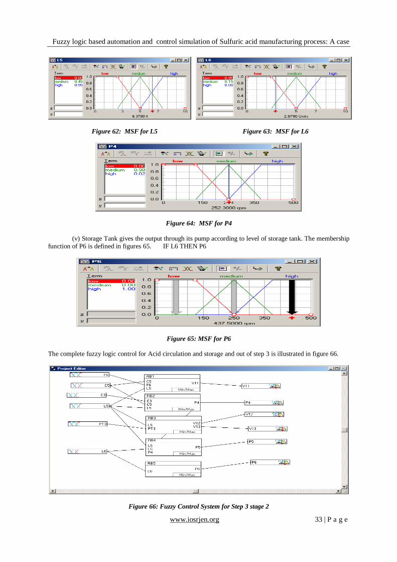
(iv) Storage Tank’s pump runs on level of circulating and storage tank’s level and circulating pump’s speed
condition. The membership function of each are defined in figures 62-64. IF L5 & L6 & P4 THEN P5
Fuzzy logic based automation and control simulation of Sulfuric acid manufacturing process: A case
www.iosrjen.org 33 | P a g e
Figure 62: MSF for L5 Figure 63: MSF for L6
Figure 64: MSF for P4
(v) Storage Tank gives the output through its pump according to level of storage tank. The membership
function of P6 is defined in figures 65. IF L6 THEN P6
Figure 65: MSF for P6
The complete fuzzy logic control for Acid circulation and storage and out of step 3 is illustrated in figure 66.
Figure 66: Fuzzy Control System for Step 3 stage 2

Fuzzy logic based automation and control simulation of Sulfuric acid manufacturing process: A case
www.iosrjen.org 34 | P a g e
V. Results The Fuzzy logic system made for step 1 is controlling the production of Sulfuric Dioxide gas with high
temperature. Here the temperature and volume both are controlled. In addition if the limits exceeded then the
production would stop and the same for the moister contamination would also be controlled. Different control strategies are fulfilled i.e control achieved for the sulfur melting, control achieved for pumping of sulfur and
cleaning of sulfur and control achieved for air burner to producing sulfuric dioxide gas which is depicted by Time
plot for HP in figure 67. In second control system, boiler and feed to the boiler of both water and sulfuric dioxide
gas are controlled and on reaching the limit the feed of both would stop. But this also would increase the Air
Burner’s temperature and pressure which will be controlled by the first controller. The results are shown in figure
68 which shows that control is achieved for this particular process.
Figure 67: Time Plot for HP Figure 68: Time Plot for V3
The third control system controls feed to reactor and feed of coolant to heat exchanger respectively.
Figure 69 shows time plot for the control achieved in the particular process. The time plot shows that control is
achieved for this particular process. Fourth & fifth control system controls feed of sulfuric trioxide to the
absorber, vent of residue sulfuric trioxide to the environment, concentration control of both stages of absorber (by
feeding sulfuric trioxide gas to first stage and by feeding low concentration sulfuric acid to the second stage this is
what the pumping of sulfuric acid through the absorber) and storage of ready to dispatch sulfuric acid. The time plot in figure 70 shows that control achieved in.
Figure 69: Time Plot for V6 Figure 70 : Time Plot for V9
VI. Conclusions Five fuzzy control systems for the entire plant have been designed with loop identification, which is
showing consistent results as elaborate in previous sections. If this work would be done by conventional method
then it would require controller for each loop, thus fuzzy control system reduces both modeling for the process-
plant and detailed analysis for each loop for conventional control system. In addition expanded span with the help
of linguistic variables give better approach for production with least errors; this shows reliability for this control
phenomenon. The approach which circumvents the need for elaborating mathematical model of the complex
chemical process and allows the use of qualitative information as linguistic rules is making knowledge base by
integrating all individual fuzzy control loops and making a single control system. Mass Production of Sulfuric
Acid from the higher capacity plant require to control number of melting tanks, air burners, west heat boilers with
reactors and absorber. Neural fuzzy control may provide better solution for the control of large process plant.

Fuzzy logic based automation and control simulation of Sulfuric acid manufacturing process: A case
www.iosrjen.org 35 | P a g e
References [1] Anna vasickaninova, Monika Bakosova, Dalibor Puna, Fuzzy Logic Control of a Chemical Reactor With Disturbances, 33rd
international conference of SSCHE, May 22–26, 2006, Tatransk´e Matliare, Slovakia, vol. 132 pp. 1-8.
[2] Saeed Vaneshani and Hooshang Jazayeri-Rad, Nonlinear control of a chemical plant employing a combination of fuzzy logic and
particle swarm optimization Techniques, International Journal Of Computer Applications (0975 – 8887) volume 33– no.9, November
2011, pp 6-13.
[3] E. R. Nucci; R. G. Silva; T. C. Gomes; R. C. Giordano; A. J. G. Cruz, a Fuzzy logic Algorithm for Identification of the Harvesting
threshold during PGA production by Bacillus Megaterium, Brazilian journal of chemical engineering, vol.22 no.4, sao paulo Dec.
2005, pp 1-6.
[4] Vasickaninova, M. Bakosova, Cascade fuzzy logic control of a Chemical Reactor, 15th int. conference process control 2005, Strbske
Pleso, Slovakia, pp1-5, vol.175 June 7–10, 2005.
[5] M. santos, J.M. De La Cruz, S. Dormido, Influence of the information processing in fuzzy logic controllers, IPMU 96, Information
Processing and Management of Uncertainty in Knowledge Based Systems , Granada, Spain, July 1-5, 1996.
[6] P.B. Osofisan, and O.J. Obafaiye, fuzzy logic modeling of the fluidized catalytic cracking unit of a petrochemical refinery, The
Pacific Journal of Science and Technology, volume 8. No. 1. May 2007 (spring), pp59-68.
[7] Dinesh Singh Rana and Rajiv Sharma, “Fuzzy Logic Based Automation of Green House Environmental parameters for
Agroindustries-A Simulation Approach” IJAER , Vol6 No.5(2011)pp662-666
[8] Rajvir Sharma, Dinesh Singh Rana etal, “A Fuzzy Logic based Automatic Control of Rotary Crane (A Simulation Approach)”,
Advance Materials Research, Vols.,403-408(2012)pp4659-4666
[9] D.F. Ahmed, S.K.H. Al-Dawery and H.A.O. Al-Anbari, On-Line Control of the Neutralization Process Based on Fuzzy Logic,
Emirates journal for engineering research, vol. 12 (2), 89-97 (2007).
[10] Sourabh Dash, Raghunathan Rengaswamy , Venkat Venkatasubramanian, Fuzzy-logic Based trend Classification for Fault Diagnosis
of Chemical Processes, Computers and Chemical Engineering Vol.27 , pp. 347-/362, 2003