fuzzy controller based micro grid connected low voltage ... · ... microgrid, renewable energy,...
TRANSCRIPT
Fuzzy Controller Based Micro Grid Connected Low Voltage Network with Distributed Energy Sources for Losses Minimization and Voltage ControlBagam Srinivasarao*, Yerra Sreenivasarao** and SVNL Lalitha***
Abstract: Microgrids are becoming important parts of electric power distribution networks. Microgrids are typically comprised of both inverter interfaced (e.g. double-fed induction generator (DFIG), solar photovoltaic (PV) system) and non-inverter interfaced (e.g. synchronous generator) renewable energy generators (REGs), hence their dynamic characteristics are significantly different from the conventional grids comprised of centralised synchronous generators. Different inherent characteristics of REGs, power dispatch levels, relative REG capacities, and external grid characteristics are some of the important features of significant interest in relation to microgrid dynamic behavior. In this paper the main components of Microgrid and the technique on how the Microgrid central controller was developed is also explained. The result from simulation study of Microgrid system is presented to demonstrate the workability of the concept. The modeling and simulation is performed in MATLAB-SIMULINK software. The simulation shows quite promising results. The Microgrid controller managed to control the voltage and frequency in both grid connected and islanding mode. An active power loss is also significantly reduced.
Keywords: Microgrid, renewable energy, distributed generation, coordinated voltage control.
INTRODUCTION1. Recent technological developments in the micro-generation domain, the need of reducing emissions, investment reduction for future grid expansion and electricity business restructuring are the main factors responsible for the growing interest in development of micro-grids. Micro grids comprise of low voltage distribution systems with distributed energy resources, such as solar photovoltaic systems and wind power generation systems , together with energy storage devices. These systems are interconnected to the medium voltage distribution network, but they can be also operated isolated from the main grid. From the consumer point of view, microgrids provide both electricity and thermal needs and in addition enhance local reliability, reduce carbon emissions, improvement in power quality by supporting voltage and reducing voltage dips and potentially lower costs of energy supply. From the utility point of view, application of distributed energy sources can potentially reduce the demand for distribution and transmission facilities. Clearly, distributed generation located close to loads will reduce flows in transmission and distribution circuits with two important effects: loss reduction and ability to potentially substitute for network assets. Furthermore, the presence of generation close to demand could increase service quality seen by end customers.
Microgrids provide network support in times of stress by relieving congestions and aiding restoration after faults. The development of microgrids can contribute to the reduction of emissions and the mitigation of climate changes. This is because of existing and currently developing technologies for distributed generation units are based on renewable energy sources and micro sources that are characterized by very low emissions. Technical challenges associated with the operation and control of microgrids are immense. Ensuring stable
* EEE Department, Laqshya Institute of technology & Sciences, Khammam. Email: [email protected]** EEE Department, BVSR Engineering College, Chimakurthy. Email: [email protected]*** EEE Department, K.L. University, Vijayawada. Email: [email protected]
I J C T A, 10(5) 2017, pp. 507-514© International Science Press
508 Bagam Srinivasarao, Yerra Sreenivasarao and SVNL Lalitha
operation during network disturbances, maintaining stability and power quality in the islanding mode of operation requires the development of sophisticated control strategies for microgrid’s inverters in order to provide stable frequency and voltage in the presence of arbitrarily varying loads.
In this research work, the main purpose of having Microgrid is to reduce the negative impact of PV output variation on the voltage and frequency. At the meantime Microgrid also is also expected to reduce active power losses in the network. The Microgrid controller should be able to manipulate the reactive power output from the renewable RE generators without reducing their active power dispatch capability.
MICROGRID POWER SYSTEM2. Microgrid is a small power system with the ability to operate in parallel or independently with the main grid. Microgrid capacity extends from a few kilowatts to a few Megawatts. It is actually a cluster of small capacity generating units together with energy storage devices and controllable loads connected to a low voltage network and operated to supply the electrical energy to local area for various purposes [6]. Microgrid concept is believed to be a part of evolution of power system that comprises distributed generation. The unique features of Microgrid are; it can be operated as a part of medium or low voltage network and it can also operate autonomously in an islanded mode, which enhances reliability of supply in case of faults in upstream network. It can be resynchronized back to the network after restoration of the upstream network. In Microgrid, distributed geneators (DG) will generate sufficient energy to supply most or all of the local load demand [3, 5-6].
Microgrid is a new energy source and grid management technology which has emerged at the end of last century and also it is the grid controlled independently, provides power with distributed generation systems. In microgrid, renewable and clear sources are involved, maximum use of present energy and management of demand. A microgrid system consists of a part of main grid and industrial and commercial applications can work independent from the grid or dependent to grid. Use of power electronics converters in these system affects the quality of the system and also requires new control regulations
As Microgrid is a new concept, it requires a physical test-bed to prove its working concept before being implemented. Even though the control method proposed in [7-8] had been demonstrated to effectively control the voltage, the demonstration is only through digital simulation. There is no guarantee that the method works in the physical system. The need for a test-bed is recommended to test the method or any similar approach. The test-bed should contain various type of DG, communication infrastructure and programmable central controller in addition to typical equipment available in conventional electric distribution network.
MICROGRID COMPONENTS3. This Microgrid is comprise of photovoltaic generation sources, fuel cell generation sources, battery storage, adjustable load and two natural loads. The layout of this Microgrid is depicted in Figure 1. Interfacing PV sources, FC and BESS to 0.4 kV busbar, there are variable impedances to simulate the cable distance.
CONTROL OF MICROGRID4. Microgrid controller is designed to operate autonomously by predicting and dispatching the power reference of the Microgrid active sources. Optimization process is used in finding the power references for these sources. The main objective is to keep the voltage inside Microgrid within operational limit at all times. In the optimization however, the objective function is to minimize active power losses. The voltage magnitude is treated as a constraint. [3, 5-6].

509Fuzzy Controller Based Micro Grid Connected Low Voltage Network with Distributed Energy Sources for...
Figure 1: Proposed Microgrid architecture
Mathematically, the optimization problem is written as,
min Ploss (PFCGS, PBESS, QPVGS, QFCGS, QBESS) (1)
where,
PFCGS : active power of fuel cell generation system
PBESS: active power of battery energy storage system
QPVGS : reactive power of PV generation system
QFCGS : reactive power of fuel cell generation system
QBESS : reactive power of battery energy storage system
The objective function is subjected to,
A. Cable loading limits:
Max Nline_ line_
Ci ij j
j£
" Π(2)
B. Bus voltage limits:
u u u jj jjmin max£ £ " ŒNB (3)
C. RE active power limits:
P P P NRE RE RE REmin max
j j j
j£ £ " Œ (4)
D. RE reactive power limits:
Q Q Q NRE RE RE REmin max
j j j
j£ £ " Œ (5)

510 Bagam Srinivasarao, Yerra Sreenivasarao and SVNL Lalitha
where, NB is the number of buses, NC is the number of cables and NRE is the number of RE units. [3, 5-6].
The inputs are forecast of PV output from BIPV, instantaneous power from the upstream network and forecast of Microgrid natural load. The outputs are the BIPV reactive power reference and power reference for FCGS and BESS.
DESIGN OF FUZZY CONTROLLER5. A fuzzy logic controller is designed to track actual generator speed to the reference speed with small time delay. Fuzzy Controller is designed to generate reference stator current along d-axis (Ids*) with inputs to the fuzzy controller are error and rate of change of error between reference and actual DC link voltages. The controller operates on a per-unit basis so that the response is insensitive to system variables and the algorithm are universal to any system.
The membership functions of inputs and output of the fuzzy controller are shown in Figure 2, Figure 3 and Figure 4 respectively. Triangular symmetrical membership functions are suitable for the input and output, which give more sensitivity especially as variables approach to zero value. The width of variation can be adjusted according to the system parameters. In the proposed fuzzy System, ten fuzzy sets have been considered as variables: Negative Big (NB), Negative Medium (NM), Negative Small (NS), Zero (ZE), Positive Small (PS), Positive Medium (PM), Positive Big (PB).
Figure 2: Membership Functions for Error
Figure 3: Membership Functions for Change of Error

511Fuzzy Controller Based Micro Grid Connected Low Voltage Network with Distributed Energy Sources for...
Figure 4: Membership Functions for Ids Reference
The Fuzzy rules considered for fuzzy controller are given in Table 1.
Table 1 Fuzzy Rules for Fuzzy Controller
Change of Error
ErrorNB NM NS ZE PS PM PB
NB NB NB NB NB NM NS ZENM NB NB NB NM NS ZE PSNS NB NB NM NS ZE PS PMZE NB NM NS ZE PS PM PBPS NM NS ZE PS PM PB PBPM NS ZE PS PM PB PB PBPB ZE PS PM PB PB PB PB
MODELING AND SIMULATION OF MICROGRID NETWORK6. All generation systems inside Microgrid are modelled as a three phase detail models. The whole Microgrid network with its components is depicted in Figure 5. BIPV, FCGS and Battery energy storage system (BESS) interface to the low voltage network via 3 phase power electronic converter utilizing IGBTs as switching devices. The switching of IGBT is controlled by signal generated by pulse width modulation method (PWM). The voltage references for PWM are calculated by inverter controller. The controller is implemented in dq coordinate which enable the independent control of active and reactive power. The inverter control method is explained in more detail in [6].
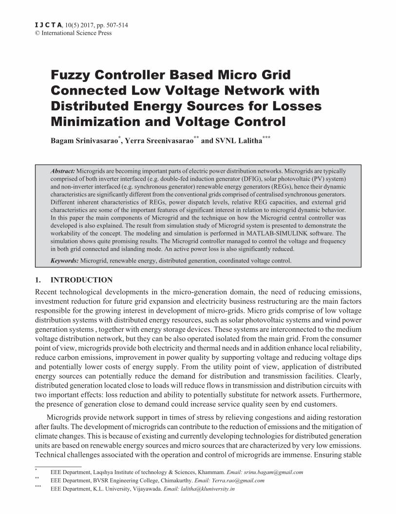
Figure 5, Figure 6 and Figure 7 display the output voltage and current respectively from BIPV, FCGS and BESS. All the waveform is captured during full generation capacity at steady state operation. Voltage waveforms seem to be almost perfectly sinusoidal but the current waveform looks distorted. From detail analysis on the waveform, the total harmonic distortion for voltage and current are tabulated in Table 2.
As can be seen the Figure 7 that current output from FCGS is more distorted as compared to the current output from PVGS and BESS as depicted in Figure 5 and Figure 7. With the Fourier transform analysis, the value of distortion for FCGS was calculated to be nearly 2% for THDv and close to 10% for THDi. This value are consider high for modern inverter that utilizing IGBT devices for switching. This is something

512 Bagam Srinivasarao, Yerra Sreenivasarao and SVNL Lalitha
interesting to be found. Even though the interfacing converter is utilizing exactly the same control algorithm, the distortion measured in current output is not similar.
Figure 5: PVGS output voltage and current
Figure 6: FCGS output voltage and current
513Fuzzy Controller Based Micro Grid Connected Low Voltage Network with Distributed Energy Sources for...
Figure 7: BESS output voltage and current
Table 2 Total Harmonic Distortion
Source Voltage THDV(%) Cuttent THDI(%)
BIPVPhase a 0.35 % Phase a 5.03 %Phase b 0.35 % Phase b 4.95 %Phase c 0.34 % Phase c 4.87 %
FCGSPhase a 1.85 % Phase a 9.31 %Phase b 1.86 % Phase b 9.07 %Phase c 1.86 % Phase c 9.45 %
BESSPhase a 0.25 % Phase a 4.75 %Phase b 0.26 % Phase b 4.76 %Phase c 0.26 % Phase c 4.62 %
During islanding mode, the dispatch power from each generation inside Microgrid is change accordingly so that the voltage and frequency can be maintained within operation limit. For this case study, the allowable variation of frequency is ±1% of nominal frequency 50 Hz. For the voltage the tolerance is between +10% and -6% of nominal voltage of 400 V. This tolerance limits are the values Gazette in [5-6] and they are assumed to be the same for both grid connected and islanding mode for Micro grid. It is clearly seen that the frequency and voltage varies throughout the simulation but the variation is still within allowable tolerance.
All the waveform is captured during full generation capacity at steady state operation. Voltage waveforms seem to be almost perfectly sinusoidal but the current waveform looks distorted. Even though the interfacing converter is utilizing exactly the same control algorithm, the distortion measured in current output is not similar. This finding indicate that the individual converter is claimed to produce very low current total

514 Bagam Srinivasarao, Yerra Sreenivasarao and SVNL Lalitha
harmonic distortion typically less than 5% [4], when it is connected to the bigger electricity network, the current THD at the point of interconnection can be higher. This is due to the facts that a certain harmonic components resonate with the system impedance or the existing electrical network already contaminated with the harmonic. In addition, the converter contributes higher harmonic contents.
CONCLUSION7. Microgrid has two modes of connection: first is Grid coupled mode and second is isolated mode. In the first mode, microgrid is connected to the main grid via PCC. In the isolated mode, microgrid is isolated from the main grid. The main advantage of microgrid is combine all benefits of renewable energy sources to reduce the carbon generation and power generation. The method of how the Microgrid central controller was developed is also explained. The result from simulation study of Microgrid system in the project is presented to demonstrate the workability of the concept. The simulation results show the promising results. The Microgrid controller managed to control the voltage and frequency in both grid connected and islanding mode as well as maintained them within mandatory operational limit.
ReferencesWanrong Tang and Ying Jun (Angela) Zhang,” Optimal Battery Energy Storage System Control in Microgrid with 1. Renewable Energy Generation”, 2015 IEEE International Conference on Smart Grid Communications (Smart Grid Comm): Data Management, Grid Analytics, and Dynamic Pricing.S. Chowdhury, S.P. Chowdhury, and P. Crossley, Microgrids and ActiveDistribution Networks. London, U.K.: IET, 2009.2. S. Suryanarayanan and E. Kyriakides. (March 2012). Microgrid: An Emerging Technology to Enhance Power System 3. Reliability, IEEE Smart Grid Newsletter[Online], Available smartgrid.ieee.orgN.W.A. Lidula and A.D. Rajapakse, “Microgrids research: a review of experimental microgrids and test systems,” 4. Renewable and Sustainable Energy Reviews, Vol. 15, No. 1, pp. 186–202, 2011.D. Trebolle etc. all, “Active Distribution System Management”, in 5. Proc. 22nd International Conference on Electricity Distribution, Stockholm, 10-13 June 2013.M.Z.C. Wanik, Simulation and Management of Distributed Generation: Green Energy Integration to Electric Power 6. System, Lambert Academic Publishing, Saarbrueken, Germany, 2011.M.K.N.M. Sarmin, W. Nakawiro, M.Z.C. Wanik, “Coordinated Voltage Control in Distribution Network with Renewable 7. Energy based Distributed Generation,” Engineering, Jan. 2013, 5, pp:208-214.M.Z.C. Wanik, I. Erlich and A. Mohamed, “Predictive var management for distributed generators”, in 8. Proc. of 2010 International Power & Energy Conference (IPEC 2010), 27-29 Oct. 2010, Singapore.M.Z.C. Wanik, I. Erlich and A. Mohamed, “Inteligent management of distributed generators reactive power for loss 9. minimization and voltage control”, in Proc. of IEEE MELECON 2010, Malta.