fuzzpups - fuzz dog's pedal partspedalparts.co.uk/docs/fuzzpups.pdf · fuzzpups lovely little...
TRANSCRIPT

FuzzPupsLovely little boxes of joy with a
totally standardised build pattern
Contents of this document are ©2016 Pedal Parts Ltd.No reproduction permitted without the express writtenpermission of Pedal Parts Ltd. All rights reserved.

What’s a FuzzPup?It’s our new system for building 1590A pedals with a standardised format for all thenon-PCB components, and a connection system common across every single circuit.
What’s this document?A general guide for building these beauties that applies to each and every one. Thatway we don’t have to include this information in every single document for every singlecircuit. “Why? It’s a PDF - it doesn’t cost anything.” If we decide to change any aspect ofthis standard in future we only need to change this single document. Probably.
Before you startDue to the nature of these builds, i.e. there’s a lot going on in a very confined space,they are fiddly to complete. You should only attempt these builds if you have patience, alight touch and are comfortable with tight spaces.
Still before you startRead the full document that applies to the circuit you’re building as well as this one.There may be some specific requirement of that particular build which isn’t covered bythe information contained within this PDF.
General, but very important tipsGet your components as close to the PCB as possible. There isn’t much heightclearance when boxing up, so any film caps that are sitting even a couple of mm off theboard could mean the difference between a successful build and a disappointingfailure. If you’re confident enough to solder ICs rather than use sockets, do.
Keep your soldering neat, and ensure you cut your component legs as tight to thesolder joints as possible. Anything sticking too far out of the bottom of the PCB willstop it getting right down onto the body of the jacks, and your lid won’t fit on the box.
Electrolytic capacitors - long lead (+) to square pad.
Diodes - lead nearest to the stripe (-) to square pad.
LEDs - short leg (-) to square pad.

You’ve read the circuit-specific instructiondocument, right? Built the circuit, now it’stime to test it.You may have noticed you maybe don’thave flying leads coming off your maincircuit board connections - you’ve got aneat row of 6 header pins instead. Howdo you test the board?
We have a few options...
The easiest way is to add some flyingleads. If you’re going to wire up yourcircuit with a top-mounted DC socketand using the jack connections from themain circuit board, you will have wiresattached to the PCB you can use. You’regood to go. Connect them up to your testcontraption of choice (we highlyrecommend having a tester circuit -they’re not going to break the bank). Ifyou don’t have a test unit you’ll have towire up your jacks and DC socket. If yougive it some thought and make the wiresthe right length for your final assembly(read further on in this doc) then youwon’t have to undo the jack connectionslater.
If you intend to do your final circuitwiring using the daughterboardconnections, you can still test the circuitas above. Add the jack and DC wires toyour main circuit and test. Once you’rehappy its working OK you can simplydesolder or just snip them off.
Finally, if you want to keep it reallymodular and neat you can make yourselfa connector so you can simply plug yourcircuit in using the header pins.Unfortunately those pins are too big to fitthe SIL sockets we supply with our testunits. A little outside-the-box thinkinglater and we have a solution. Webutchered modified a 14-pin DIL socket -the kind you use to mount ICs - wiring itup to a 6-way ribbon cable and a row ofSIL sockets at the other end. Presto! Alead that’ll plug into our test unit and willaccept the bigger pins needed. You couldjust solder flying leads from the DIL pinsof course.
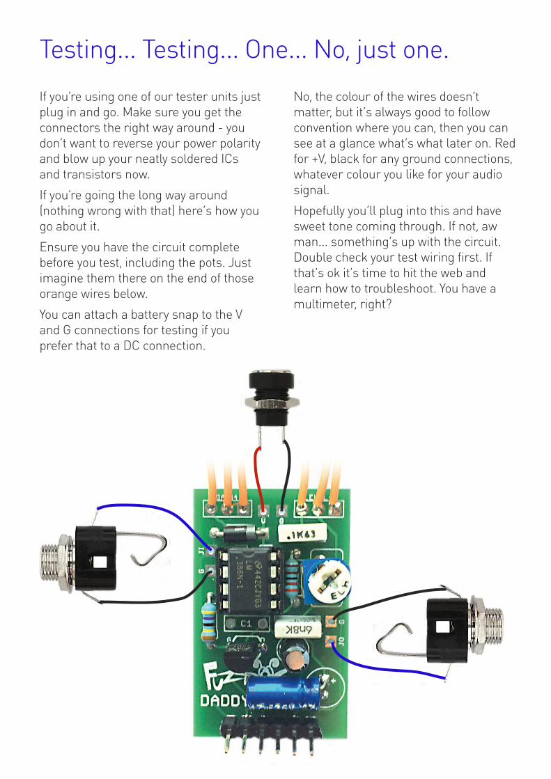
Testing... Testing... One... No, just one.
If you’re using one of our tester units justplug in and go. Make sure you get theconnectors the right way around - youdon’t want to reverse your power polarityand blow up your neatly soldered ICsand transistors now.
If you’re going the long way around(nothing wrong with that) here’s how yougo about it.
Ensure you have the circuit completebefore you test, including the pots. Justimagine them there on the end of thoseorange wires below.
You can attach a battery snap to the Vand G connections for testing if youprefer that to a DC connection.
No, the colour of the wires doesn’tmatter, but it’s always good to followconvention where you can, then you cansee at a glance what’s what later on. Redfor +V, black for any ground connections,whatever colour you like for your audiosignal.
Hopefully you’ll plug into this and havesweet tone coming through. If not, awman... something’s up with the circuit.Double check your test wiring first. Ifthat’s ok it’s time to hit the web andlearn how to troubleshoot. You have amultimeter, right?

Fitting youroffboard connectorsYou’ll have a pair of mono 1/4” jacksockets (Lumberg KLBM3), a mini 8mmDC socket and a 3PDT footswitch. Thereare only two different drilling patternsfor these components if you’re using anenclosure supplied by us. The onlydifference between them is the positionof the DC socket - either at the bottomnext to the footswitch, or right at the topof the enclosure.
The holes for the DC and jacks aredrilled close to the top surface of theenclosure to allow plenty of space forthe circuit to fit. It’s tight, but it works.As the bodies of the jacks are plastic youdon’t need to worry about shorting outanything on the underside of your PCB ifthey touch them.
Position everything as shown above.Note the orientation of the jacks - this isimportant.
The DC socket should be rotated ataround 45° as shown below to give extraclearance between it and the jack socket.It looks like a lot of space, but when ajack is inserted the socket will bend outtowards the footswitch.
When mounting the footswitch youshould give the bottom nut a turn or twoso the switch body sits away from the topsurface of the box. The tips of the 9footswitch lugs should sit just below theedge of the enclosure. Any higher andthey may short out against the box lid.Any lower and you may not have room tofit your circuit in the box.
All mounted and tightened up? Good.Next...
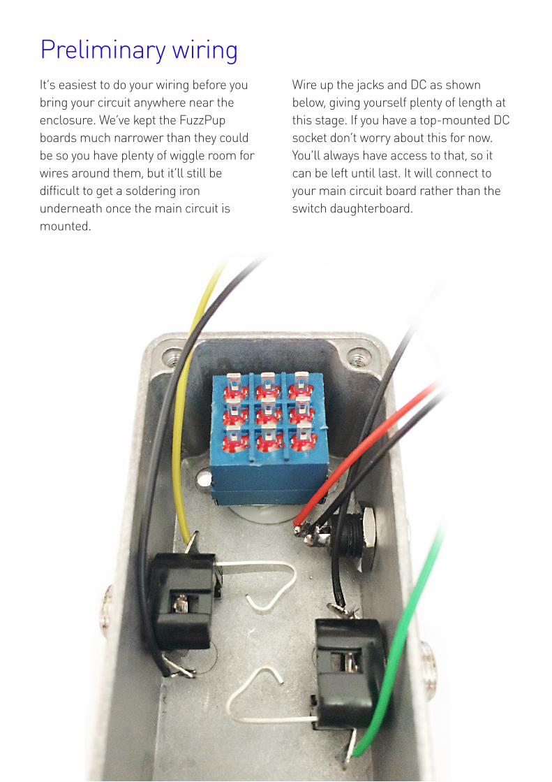
Preliminary wiringIt’s easiest to do your wiring before youbring your circuit anywhere near theenclosure. We’ve kept the FuzzPupboards much narrower than they couldbe so you have plenty of wiggle room forwires around them, but it’ll still bedifficult to get a soldering ironunderneath once the main circuit ismounted.
gWire up the jacks and DC as shownbelow, giving yourself plenty of length atthis stage. If you have a top-mounted DCsocket don’t worry about this for now.You’ll always have access to that, so itcan be left until last. It will connect toyour main circuit board rather than theswitch daughterboard.

Switch wiringThere are a few different ways to connectup your wires. By far the easiest is asshown below. All your offboardconnections are made to the footswitchdaughterboard. To do this you should laythe daughterboard in position on thefootswitch and check how much wireyou’ll need for each connection. Toomuch and you’ll end up having troublecramming all the extra beneath thePCBs when you do your final assembly.Too little and you won’t be able tomanoeuvre your PCBs into position.Around a half inch of slack in each caseis good.
gYou should use the JI (jack in) and JO(jack out) connections on the outeredges of the daughterboard as shownbelow, rather than the ones on the frontedge. You need that space free toconnect your main circuit board.
The shorter pin of the DC socket is yourGND, the longer is your +V.
The jack socket grounds are the oneswith black wires connected to them inthe picture.
You should solder in your LED CurrentLimiting Resistor (CLR) before youconnect the wires. Easier, honestly.
With this wiring configuration you onlyneed to connect the daughterboard andmain circuit board with the four mainpads - IN, V, G and OUT. The leadingedge JI and JO pads are now redundant.However, we recommend still using allsix connections to make a stronger joinbetween the two boards.

Don’t forget the LEDReally - don’t! Once you’ve soldered thedaughterboard in place on the footswitchit’ll be difficult to get the LED in there.
Pull it through the daughterboard fromthe bottom. Long (+) leg goes into theround pad.
gOnce its pulled all the way through youcan bend the legs out slightly to stop itfalling back out, or just be careful not tolet it. Don’t worry about how far the LEDis from the PCB right now. That’ll fallinto position soon.

You’ve already built and tested your maincircuit so we know we’re good to go withthat. Get your daughterboard intoposition just above the footswitch. Yes,we know the one in the image has nowires attached - we forgot to takepictures before soldering up the onewe’d been building. Position your maincircuit’s header pins into thedaughterboard as shown. Now drop thedaughterboard into position on thefootswitch.
You may find the main circuit boardcatches on the edge of the footswitch.Don’t worry, it’s time to wiggle. There’slots of play in the pads of thedaughterboard, so pull it slightly forwardon the footswitch. You should have plentyof space and the main circuit will dropdown nicely onto the top of the jacksockets, even if you didn’t mount theheader pins at an angle.
Make sure your wires aren’t stuckbetween the PCB and jacks. We madethat PCB narrower than the enclosurefor a reason.
Time to marry your PCBs

With your main circuit nicely lying on thejacks, check your daughterboardpositioning. You should be able to have itpressed all the way down onto the bodyof the footswitch, bu it doesn’t matter ifthe best fit is slightly above. Nor does itmatter if the header pins aren’t pushedright up so the plastic casing on them ispressed against the daughterboard. Thisis a bit of a zen procedure, finding thehappiest place for both boards to findtheir forever home.
Once you’re happy, solder in thefootswitch lugs. Do one first and recheckthe fit. It’s very easy to reposition thedaughterboard if you only have oneconnection, very difficult once you havetwo or more. Once all nine are soldered,do your header pin joints. Lastly, pushyour LED down through thedaughterboard into the hole in theenclosure and *carefully* solder it. Takeyour time with that and use a heatsink.If you burn it out you’ll have a nightmarereplacing it.
Mission, hopefully, accomplished

As we said earlier, there’s more than oneway to wire these up.
Take a look at the boards opposite - theuniversal footswitch daughterboard andthe Mini Llama.
The main connection strip on both isidentical.
JI Jack In
CI Circuit In
V +V Supply
G Ground
CO Circuit Out
JO Jack Out
Where you see other pads across thetwo boards with the same label, theseare all directly connected to each otherwhen the two boards are joined with the6-pin headers. So, the JI pad on the mainstrip of the daughterboard connects to JIon the main strip of the Llama, as wellas the one on the left hand side of thedaughterboard and the one near the topleft hand side of the Llama. Thereforeyou can make your Jack In connectionfrom either the daughterboard or themain board. Same goes for the Vconnection. Once the two boards arejoined you can connect your DC jack toeither the V and G pads on the bottomleft of the daughterboard OR the ones onthe top of the Llama.
Ignore the fact there are numbers afterthe G pads on either side of the Llama.We are. Hey, there’s an example over on the next
page >>>>>>
More than one way to skin your tofu

On the example below we’ve wired theboth the jacks and the DC socket fromthe main circuit board. The onlyconnections on the daughterboard arethe 6-way header pin and the LED andcurrent limiting resistor. It’s all good.
So, give your build some thought beforeyou start and plan what you’re going towire from where. If you know whereyou’re heading the end is a lot easier tofind. Not sure if that qualifies as zen, butit certainly make sense. Enjoy!
Alternative wiring example

This is a guide only. If you’re drilling yourown enclosure please double checkeverything before starting.
The holes for the pots are less critical.Simply ensure you have enoughclearance for the screw hole pillars inthe corners of the enclosure. If you’remaking a two-pot circuit using 9mmAlpha jacks they should be at least16mm from the top edge of theenclosure.
Recommended drill sizes:
Jacks 10mm
Footswitch 12mm
DC Socket 8mm
Pots 7mm
Drilling guide
42
13
27
51
18
9.5