future technology devices international ltdmp3 and other audio format files from a usb flash disk...
TRANSCRIPT

Use of FTDI devices in life support and/or safety applications is entirely at the user’s risk, and the user agrees to defend, indemnify and hold harmless FTDI from any and all damages, claims, suits or expense resulting
from such use.
VMusic3 Version 1.0
Document Reference No.: FT_000738 Clearance No.: FTDI# 336
Future Technology
Devices International Ltd
Datasheet
VMusic3 Vinculum-II
Application Module VMusic3 is a USB host and MP3/WMA Player application module with an enclosure. The
default firmware of the VMusic3 supports audio playback and UART/SPI communications
with the embedded USB host controller and USB host port. VMusic3 can be used to read MP3 and other audio format files from a USB flash disk process the data and output the
stereo audio through the line-out header and headphone jack.
1 Introduction
VMusic3 is designed to support quick and easy
integration of a UART/SPI application with a
USB client device. VMusic3 also supports
playback of MP3 and WMA. The VMusic3 is
packaged in a neat enclosure displaying a bi-
colour LED, making it suitable for
incorporating into finished product designs.
The VMusic3 utilises FTDI’s Vinculum-II (VNC2-
48L1B) dual USB host controller IC. This IC is a
microcontroller and USB host controller; it can
be reprogrammed using the UART interface or
the Vinculum-II debugger module interface
connecter. The default firmware used is
V2MSC, this firmware supports the UART/SPI
to USB host interface and MP3 playback. This
firmware can be modified or replace with
another firmware.
The VMusic3 also utilises VLSI Solution’s
VS1053b compressed audio codec to provide
the audio play back feature. This chip operates
with the Vinculum-II and supporting firmware
when reading MP3 and WMA files from a USB
flash drive. The VS1053b processes this data
and outputs the stereo audio to the headphone
jack and line-out header. Connecting
headphones or speakers to either of these
ports transduces the audio data into sound.
For details on the Vinculum-II collateral please
click http://www.ftdichip.com/Products/ICs/VNC2.htm.
1.1 Features
VMusic3 has the following features:
MP3 and WMA playback
Vinculum-II microcontroller/USB host
controller IC.
USB “A” type socket to connect to USB
client devices.
2mm (0.08”) pitch 8 pin header used for
the UART/SPI interface.
Connects directly and communicates with
a FTDI TTL-232R-3V3-2mm USB-UART
cable.
Jumper selectable UART and SPI
interfaces, both operating 3.3V TTL/CMOS.
Pre-programmed with V2MSC firmware.
Vinculum-II debugger module port under
the enclosure, for changing the firmware
and debugging.
UART programming mode control pins
PROG# and RESET# are connected to an
internal header.
Reprogrammable over USB Port from
flash drive.
The VMusic3 and all components used are
Pb-free (RoHS compliant).

2
Copyright © 2013 Future Technology Devices International Limited
VMusic3 Version 1.0
Document Reference No.: FT_000738 Clearance No.: FTDI# 336
Table of Contents
1 Introduction ................................................................................... 1
1.1 Features ........................................................................................................ 1
2 Ordering Information ..................................................................... 3
3 VMusic3 Signals and Configurations ............................................... 3
3.1 VMusic3 Pin-Out ............................................................................................ 3
3.2 VMusic3 Jumper Configuration ...................................................................... 3
3.3 Interface Discriptions ................................................................................... 4
4 VMusic2 and VMusic3 comparisons................................................. 4
5 VMusic3 Application Examples........................................................ 5
5.1 UART Interface to PIC Example ..................................................................... 5
6 VMusic3 Commands Details ............................................................ 6
7 VMusic3 Electrical Details ............................................................... 7
7.1 SPI Interface Timing ..................................................................................... 7
8 VMusic3 Max-Ratings ..................................................................... 9
9 VMusic3 Mechanical Details ............................................................ 9
10 VMusic3 Circuit Schematic ............................................................ 10
11 Contact Information ..................................................................... 11
Appendix A - List of Figures and Tables ................................................................. 13
Appendix B – Revision History .............................................................................. 14

3
Copyright © 2013 Future Technology Devices International Limited
VMusic3 Version 1.0
Document Reference No.: FT_000738 Clearance No.: FTDI# 336
2 Ordering Information
Module Code Utilised IC Code Description
VMUSIC3 VNC2-48L1B USB host application module with MP3 playback and enclosure.
3 VMusic3 Signals and Configurations
3.1 VMusic3 Pin-Out
Figure 3.1 – VMusic3 Pin Out (in UART mode)
The pin-out is illustrated in Figure 3.1.
3.2 VMusic3 Jumper Configuration
The VMusic3 comes preloaded with the V2MSC firmware and the jumper is set to UART mode by default. Adjusting the jumpers accordingly configures the module to operate in SPI mode.
The interface modes of the VMusic3 running on a V2MSC firmware are given in Table 3.1
UART/SPI Interface Mode
Pull-Up UART
Pull-Down SPI Table 3.1 – VMusic3 Jumper Box

4
Copyright © 2013 Future Technology Devices International Limited
VMusic3 Version 1.0
Document Reference No.: FT_000738 Clearance No.: FTDI# 336
3.3 Interface Discriptions
Pin No. Name Type Description
1 GND PWR Signal ground
2 RTS# Output Request To Send control output – Handshake signal
3 5V0 PWR 5V supply input
4 RXD Input Receive asynchronous data input
5 TXD Output Transmit asynchronous data output
6 CTS# Input Clear To Send control input - Handshake signal
7 NC - No Connect
8 RI#/WU Input Ring Indicator control input / Wake Up Table 3.2 – 3.3V TTL/CMOS UART Pin Out
Pin No. Name Type Description
5 CLK Input SPI clock input. Maximum frequency: 24MHz.
4 MOSI Input SPI slave serial data input
2 MISO Output SPI slave serial data output
6 SS# Input SPI slave select input Table 3.3 – 3.3V TTL/CMOS SPI Pin Out
For further details see VNC2 datasheet.
4 VMusic2 and VMusic3 comparisons
The VMusic3 is a drop in replacement for the VMusic2 for the majority of VMusic2 applications. VMusic3 uses firmware called V2MSC which is similar to V2DAP (used in VDRIVE3) with an additional module for controlling MP3 playback. However for a small number of applications that use SPI, differences exists between VMUSIC firmware and V2MSC firmware which would require some changes to be made to the
application software. For further details on this discrepancy please see AN_176 - Vinculum Comparison of VDAP and V2DAP.
Additional features of the VMusic3:
Vinculum-II can be configured by a user defined firmware
VMusic3 has an SPI master interface available (not enabled in V2MSC firmware).
VMusic3’s SPI interface can be clocked up to 24MHz
VMusic3 can be programmed using the debugger-module port in addition to programming using
the UART interface port.
VMusic3 can utilise many of the Vinculum-II sample firmware available on the FTDI website.

5
Copyright © 2013 Future Technology Devices International Limited
VMusic3 Version 1.0
Document Reference No.: FT_000738 Clearance No.: FTDI# 336
5 VMusic3 Application Example
VMusic3 can be used to play audio from a flash disk. An example is given where a PIC is used to send commands to the VMusic3 select playing option such as play, pause and skip.
It is also possible to control the VMusic3 from a PC using a TTL-232R-3V3-2mm and a terminal. See Vinculum Firmware User Manual for details on the control commands.
5.1 UART Interface to PIC Example
Figure 5.1 – MP3 playback using VMusic3 controlled by a PIC MCU
A VMusic2 compatible example is given in Figure 5.1. This example shows a VMusic3 interfacing with an external PIC MCU and supporting components. In this example four push buttons are used to control play / pause, stop, skip forward / volume up and skip back / volume down of the MP3 player.
For more information on this application see VMUSIC SPI PIC Sample on the following web page:
http://www.ftdichip.com/Support/SoftwareExamples/VinculumProjects.htm

6
Copyright © 2013 Future Technology Devices International Limited
VMusic3 Version 1.0
Document Reference No.: FT_000738 Clearance No.: FTDI# 336
6 VMusic3 Commands Details
The command set for the VMusic3 is given in Table 6.1.
For more details on Vinculum commands please see: http://www.ftdichip.com/Firmware/Precompiled/UM_VinculumFirmware_V205.pdf
Extended Command Set Short Command Set (Hexadecimal Codes)
Function
VPF∙file ↵ 1D 20 file 0D Plays a single file
VRF∙file ↵ 89 20 file 0D Repeatedly plays a single file
VST ↵ 20 0D Stops playback
V3A ↵ 21 0D Plays all MP3 files
VRA ↵ 8A 0D Repeatedly plays all MP3 files
VRR ↵ 8F 0D Repeatedly plays random MP3 files
VSF ↵ 25 0D Skip forward one track
VSB ↵ 26 0D Skip back one track
VSD ↵ 8E 0D Skip forward on whole directory
VP ↵ 8B 0D Pause playback
VF ↵ 8C 0D Fast forward 5 seconds
VB ↵ 8D 0D Rewind 5 seconds
VRD∙byte ↵ 1F 20 byte 0D Reads command register
VWR∙byte+word ↵ 1E 20 byte word 0D Writes command register
VSV∙byte ↵ 88 20 byte 0D Sets playback volume
Table 6.1 – V2MSC Command Set

7
Copyright © 2013 Future Technology Devices International Limited
VMusic3 Version 1.0
Document Reference No.: FT_000738 Clearance No.: FTDI# 336
7 VMusic3 Electrical Details
7.1 SPI Interface Timing
The following timing diagrams are for the VNC1L Legacy Interface mode of SPI slave.
SCLK
SS#
MOSI
MISO
Figure 7.1 – SPI
To start the data transfer process SS# needs to be set high, and remain high for the entire read cycle. Once the read cycle completes SS# needs to be set low for at least one clock cycle to allow another data
transfer cycle to occur.
The first bit of MOSI is the R/W bit, receiving a logic high for this bit allows data to be read from the VMusic3.The second bit is the address bit, ADD, this bit is used to select reading data from the data register when set to logic high, or from the status register when set to logic low. During an SPI Read cycle a package of data is transmitted from the VMusic3 on the MISO line from the time of the first clock cycle after the SPI ADD bit, with the MSB transmitted first.
After the data has been transferred the status of MISO can be checked to determine if the data read is
new data that has not been read before, which is indicated by a transmitted logic low. Otherwise if old data is being transmitted, which is indicated by a transmitted logic high, the read cycle needs to be repeated to get new data.
SCLK
SS#
MOSI
MISO
Figure 7.2 – VMusic3 SPI Waveforms
To start the data transfer process SPI SS# needs to be set high, and remain high for the entire write cycle. Once the write cycle SPI completes SS# needs to be set low for at least one clock cycle to allow another data transfer cycle to occur. The first bit of MOSI is the R/W bit, receiving a logic low for this bit allows data to be written to the VMusic3.
8
Copyright © 2013 Future Technology Devices International Limited
VMusic3 Version 1.0
Document Reference No.: FT_000738 Clearance No.: FTDI# 336
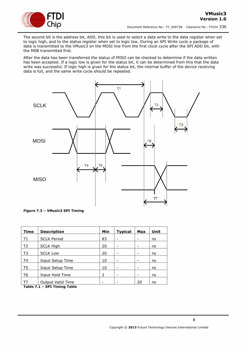
The second bit is the address bit, ADD, this bit is used to select a data write to the data register when set to logic high, and to the status register when set to logic low. During an SPI Write cycle a package of data is transmitted to the VMusic3 on the MOSI line from the first clock cycle after the SPI ADD bit, with the MSB transmitted first.
After the data has been transferred the status of MISO can be checked to determine if the data written has been accepted. If a logic low is given for the status bit, it can be determined from this that the data
write was successful. If logic high is given for the status bit, the internal buffer of the device receiving data is full, and the same write cycle should be repeated.
SCLK
MOSI
MISO
Figure 7.3 – VMusic3 SPI Timing
Time Description Min Typical Max Unit
T1 SCLK Period 83 - - ns
T2 SCLK High 20 - - ns
T3 SCLK Low 20 - - ns
T4 Input Setup Time 10 - - ns
T5 Input Setup Time 10 - - ns
T6 Input Hold Time 2 - - ns
T7 Output Valid Time - - 20 ns Table 7.1 – SPI Timing Table
9
Copyright © 2013 Future Technology Devices International Limited
VMusic3 Version 1.0
Document Reference No.: FT_000738 Clearance No.: FTDI# 336
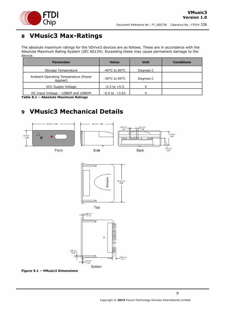
8 VMusic3 Max-Ratings
The absolute maximum ratings for the VDrive3 devices are as follows. These are in accordance with the Absolute Maximum Rating System (IEC 60134). Exceeding these may cause permanent damage to the device.
Parameter Value Unit Conditions
Storage Temperature -40°C to 85°C Degrees C
Ambient Operating Temperature (Power Applied)
-30°C to 85°C Degrees C
VCC Supply Voltage -0.3 to +5.5 V
DC Input Voltage – USBDP and USBDM -0.5 to +3.63 V
Table 8.1 – Absolute Maximum Ratings
9 VMusic3 Mechanical Details
Figure 9.1 – VMusic3 Dimensions

10
Copyright © 2013 Future Technology Devices International Limited
VMusic3 Version 1.0
Document Reference No.: FT_000738 Clearance No.: FTDI# 336
10 VMusic3 Circuit Schematic
Figure 10.1 – Module Circuit Schematic

11
Copyright © 2013 Future Technology Devices International Limited
VMusic3 Version 1.0
Document Reference No.: FT_000738 Clearance No.: FTDI# 336
11 Contact Information
Head Office – Glasgow, UK Future Technology Devices International Limited Unit 1, 2 Seaward Place, Centurion Business Park Glasgow G41 1HH United Kingdom Tel: +44 (0) 141 429 2777 Fax: +44 (0) 141 429 2758 E-mail (Sales) [email protected] E-mail (Support) [email protected] E-mail (General Enquiries) [email protected]
Branch Office – Taipei, Taiwan Future Technology Devices International Limited (Taiwan) 2F, No. 516, Sec. 1, NeiHu Road Taipei 114 Taiwan , R.O.C. Tel: +886 (0) 2 8797 1330 Fax: +886 (0) 2 8751 9737 E-mail (Sales) [email protected] E-mail (Support) [email protected] E-mail (General Enquiries) [email protected]
Branch Office – Hillsboro, Oregon, USA Future Technology Devices International Limited (USA) 7130 SW Fir Loop Tigard, OR 97223-8160 USA Tel: +1 (503) 547 0988 Fax: +1 (503) 547 0987 E-Mail (Sales) [email protected] E-Mail (Support) [email protected] E-Mail (General Enquiries) [email protected]
Branch Office – Shanghai, China Future Technology Devices International Limited (China) Room 408, 317 Xianxia Road, Shanghai, 200051 China Tel: +86 21 62351596 Fax: +86 21 62351595 E-mail (Sales) [email protected] E-mail (Support) [email protected] E-mail (General Enquiries) [email protected]
Web Site
http://ftdichip.com
Distributor and Sales Representatives
Please visit the Sales Network page of the FTDI Web site for the contact details of our distributor(s) and sales representative(s) in your country.
System and equipment manufacturers and designers are responsible to ensure that their systems, and any Future Technology Devices International Ltd (FTDI) devices incorporated in their systems, meet all applicable safety, regulatory and system-level performance requirements. All application-related information in this document (including application descriptions, suggested FTDI devices and other materials) is provided for reference only. While FTDI has taken care to assure it is accurate, this information is subject to customer confirmation, and FTDI disclaims all liability for system designs and for any applications assistance provided by FTDI. Use of FTDI devices in life support and/or safety applications is entirely at the user’s risk, and the user agrees to defend, indemnify and hold harmless FTDI from any and all damages, claims, suits or expense resulting from such use. This document is subject to change without notice. No freedom to use patents or other intellectual property rights is implied by the publication of this document. Neither the whole nor any part of the information contained in, or the product described in this document, may be adapted or reproduced in any material or electronic form without the prior written consent of the copyright holder. Future Technology Devices International Ltd, Unit 1, 2 Seaward Place, Centurion Business Park, Glasgow G41 1HH, United Kingdom. Scotland Registered Company Number: SC136640

Copyright © 2013 Future Technology Devices International Limited 13
VMusic3
Version 1.0
Document Reference No.: FT_000738 Clearance No.: FTDI# 336
Appendix A - List of Figures and Tables
List of Figures
Figure 3.1 – VMusic3 Pin Out (in UART mode) ............................................................................................. 3
Figure 7.2 – VMusic3 SPI Waveforms ............................................................................................................ 7
Figure 7.3 – VMusic3 SPI Timing ................................................................................................................... 8
Figure 9.1 – VMusic3 Dimensions .................................................................................................................. 9
Figure 10.1 – Module Circuit Schematic...................................................................................................... 10
List of Tables
Table 3.1 – VMusic3 Jumper Box ................................................................................................................... 3
Table 7.1 – SPI Timing Table .......................................................................................................................... 8
Table 8.1 – Absolute Maximum Ratings ........................................................................................................ 9
Copyright © 2013 Future Technology Devices International Limited 14
VMusic3
Version 1.0
Document Reference No.: FT_000738 Clearance No.: FTDI# 336
Appendix B – Revision History
Document Title: VMusic3
Document Reference No.: FT_000738
Clearance No.: FTDI# 336
Product Page: http://www.ftdichip.com/Products/ICs/VNC2.htm
Document Feedback: Send Feedback
Version 1.0 First release 10/04/12