future of v2x x – vehicles, smartphones, infrastructure silicon valley automotive...
TRANSCRIPT

Future of V2X
X – Vehicles, Smartphones, Infrastructure
Silicon Valley Automotive Open Source Nov 3rd 2014
Ravi Puvvala CEO, Savari

ü Established in 2008. Global HQ: Santa Clara CA with ~Forty employees Three R&D centers in CA, MI and India
ü Savari develops V2X technologies for road infrastructure & co-operative advanced driver assistance systems
ü First to market with commercial deployment in Q1 2015
ü Deployed V2X infrastructure in Arizona, California, Michigan, Virginia
ü Partnered closely with:
Ø US DOT: RITA, FHWA, NHTSA
Ø OEMs: CAMP (GM, Ford, Hyundai, Nissan, VW, Mercedes, Toyota)
Ø Transportation Research: UMTRI – MI, VTTI – VI, UofA - AZ
About Savari
2

V2X via Vehicles, Phones & Infrastructure
3

Path to Automated Vehicles
Autonomous Vehicles
Automated Vehicles
Semi Autonomous
Vehicles
Connected Vehicles
Self-braking Proximity warning
Time
Today
4

Key Information V2X Overview
� V2V is inexpensive system with many safety-related applications � V2I has similar apps, but requires complex network infrastructures � Growing driver distraction requires technology solutions like V2X
V2V vs V2I � V2V can address 75% plus of all accident (non-impaired drivers) � V2I can address remaining accidents categories � V2I has many ITS and eco-related applications
V2P vs P2I � Smartphones are supported with key enabling technologies � Communication via DSRC, Cellular to the infrastructure
Standards � US Standards – WAVE - 802.11p, IEEE 1609.2, 1609.3, 1609.4 � EU standards – 802.11p, ITS G5, Geo Networking, IPV6
Summary � V2V is least costlier way to lower accident costs � V2V is only useful if nearby vehicles/phones have V2V (network effect) � Deployment – NHTSA driven mandate in USA 2017+, EU 2015+
V2X Big Picture
5

V2V Overview

Vehicle-to-Vehicle Communications Starts with Data Broadcast
source: USDOT
7

V2V Safety Applications
Emergency brake light warning
Forward collision warning
Intersection movement assist
Blind spot and lane change warning
Do not pass warning
Control loss warning
Weather-related vehicle stabilization activation
8 8

HV
RV-1
RV-2
HV RV-1
HV
RV-1
HV
RV-1
HV RV-2 RV-1 HV
RV-1HV
EEBL
FCW
FCW1
FCW2
FCW3
FCW4
FCW5
Forward Warning
9

HV
RV-1
HV
HV
RV-1
HV
HV
RV-2
HVRV-1
RV-2
HV
RV-1
BSW LCW
DNPW1 DNPW2
DNPW
Lane Changing
10

HV
RV-1
RV-2
RV-1
RV-2 HV
HV
RV-1
RV-2
Intersections
IMA1 IMA2
LTA
IMA
11

V2I, I2V Overview

What are V2I & I2V & I2I? Ø V2I is defined by wireless data exchange between any type of (multimodal)
transportation vehicle, and immobile roadside unit
Ø Data can be exchanged between vehicles and “the infrastructure” by many different “over-the-air” interfaces
Ø USDOT’s Connected Vehicles Research Program has so far focused on 5.9 GHz band DSRC; however, and perhaps just as appropriate for mobility and environmental applications, other technologies are viable as either one or two way data exchanges:
Ø Pre & post 4G cellular, WiFi, Sirius XM, DTB Radio (eg. HD FM, TMC) Ø DSRC V2I may be operated by local or state road operators who are
best situated to utilize the transportation data currently being considered, and/or provide it to other users as necessary for particular use cases.
13

Smart Infrastructure Ø Enhanced intersection safety and efficiency
through use of vehicle trajectory data Ø Further advantages include performance
measures based on multi-modal ITS systems, capacity to provide real-time traffic information
Ø Provides opportunity to create open network that connects transportation corridors, people and data to transform the way the world moves
14

Traffic Signal Priority/Preemption
Ø Signal Preemption for emergency, freight vehicles Ø Expanded availability, more efficient handling of
multiple requests, reduction in transit delay and variability
Ø Today’s solutions are commonly based on infrared, GPS, wireless systems, and lack common service scalable integrated framework
15

Eco Driving Ø Smarter operations through vehicle awareness
of intersection state Ø Substantial improvements in fuel savings Ø This could also be extended as a service by the
infrastructure provider Ø Use of environmental sensors attached to target
vehicles (delivery vehicles for sub/urban; utility vehicles at airports, ports) creates micro-emissions and micro-weather capabilities
16
Transportation Pricing
Ø V2I technology can add opportunity for smart tags to do congestion pricing, VMT based pricing, variable parking fees
Ø Provides more opportunities to deploy V2I technologies in controlled environments Ø Airport
Ø Seaports
Ø Corridors
Ø Hot lanes
Ø Environmentally sensitive geographies
17

National footprint
Source: USDOT
18

P2V, P2I Overview

Key Enabling Technologies for P2V, P2I Context Awareness in Smartphones
Turn on DSRC at the right moment based on where you are & what you are doing. Always ON and power efficient
DSRC capable WiFi chipsets Enable DSRC without adding HW cost Ride on high penetration of WiFi chipsets in smartphones
Augmented Positioning Improve GPS positioning accuracy Enhance positioning with WiFi or Cellular and sensors
20
Source: Qualcomm

Pedestrian-to-Vehicle (P2V) Pedestrian-to-Vehicle
Ø Deploy smart phones, equipped with DSRC support to act as beacons for pedestrians
phone can alert driver to pedestrian presence in path
“pedestrian BSM” can aid awareness for vehicles
Well suited for bicyclists also
Pedestrian-to-Infrastructure
Ø Smart phone, through DSRC/cellular, transmits pedestrian presence to crosswalks / signals
enables advanced crosswalk lighting/warning scheme
enables “bundling” of pedestrian presence to vehicles
21

Pedestrian-to-Infrastructure (P2I)
22
Ø System to deliver SPaT, MAP and other SAE J2735 messages to the smartphone.
Ø Allows pedestrians to request WALK at the crosswalk.
Ø Designed to be communication medium agnostic.

Standards

Japan
Europe
US
5.875
5.885
5.895
5.905
5.915
5.925
5.865
5.855
715
725
730
710
720
5.77
5.85
5.81
Medium Range Service C
ontro
l Short Range Service
Pub
lic S
afet
y In
ters
ectio
ns
Hig
h Av
aila
bilit
y Lo
w L
aten
cy
Non-safety ITS Applicatio
ns
Future Extension:
Road Safety and
Traffic Efficiency
Con
trol
Road Safety
ITS 700 MHz G
uard
Ban
d
DSRC ARIB STD T75/T88
Gua
rd B
and
Spectrum
24

US DSRC Spectrum: Seven 10 MHz channels
• Ch. 178: • Control Channel • WAVE Service Advertisements are broadcast here, indicating how to
access services on other “Service Channels”
Ch. 172: Collision Avoidance Safety
Ch. 184: Public Safety
Reserved 5 M
Hz
CH 172
Service
10 MHz
CH 174
Service
10 MHz
CH 176
Service
10 MHz
CH 178
Control
10 MHz
CH 180
Service
10 MHz
CH 182
Service
10 MHz
CH 184
Service
10 MHz
CH 175 20 MHz
CH 181 20 MHz
5.850 GHz 5.925 GHz
25

144
140
136
132
128
124
120
116
112
108
104
100
165
161
157
153
149
64
60
56
52
48
44
40
36
IEEE channel # 20 MHz 40 MHz 80 MHz
160 MHz
UNII-1 UNII-2A UNII-2C UNII-3 5250 MHz
5350 MHz
5470 MHz
5725 MHz
NEW
96
92
88
84
80
76
72
68
169
173
177
181
5825 MHz
5925 MHz
NEW
Currently available channels New channels
Poten<al new Wi-‐Fi channels in 5 GHz band
• 802.11n introduced 40 MHz channels • 802.11ac introducing 80 MHz and 160 MHz channels • UNI-2 (A, B, C): radar is primary, Dynamic Frequency Selection
(DFS) is required by Wi-Fi
UNII-2B UNII-4
26
Source: John Kenney Slides

Ø Key is to avoid colliding with or delaying DSRC packets Ø Wi-Fi devices already avoid overlapping transmissions via
a “listen-then-talk” protocol Ø Carrier Sense Multiple Access/Collision Avoidance (CSMA/CA)
Ø Wi-Fi can detect DSRC device in area via similar function that looks for 10 MHz DSRC packet “signature”
Ø Before sending anywhere in 5.9 GHz band, listen for DSRC in all 7 channels Ø If no DSRC detected, ok to operate WLAN Ø If DSRC detected, keep out of the band for [TBD] time
“Detect-‐and-‐vacate” concept
See: J. Lansford, J. Kenney, and P. Ecclesine, “Coexistence of Unlicensed Devices with DSRC Systems in the 5.9 GHz ITS Band,” IEEE VNC 2013
27

V2X Global Standards
IEEE 802.11p ITS G5
SAE J2735, CAM, DENM IEEE1609.1-4
IPV6 Geo Routing,
BTP
US/Europe
28
SAE

US Standards Overview
DSRC PHY+MAC (IEEE 802.11p)
DSRC Upper-MAC (IEEE 1609.4)
IPv6
TCP/UDP
Messages (SAE J2735)
Min. Perf. Req. (SAE J2945) Non-safety applications
DSR
C Security (IEEE 1609.2)
DSRC WSMP
Service Advertisement
(IEEE 1609.3) 2010
2010
2010
2013
2009
Draft
29

US - WAVE Scope
OBU
WA
VE
Sta
ck
Wire
line
Sta
ck
In Vehicle Network
OBU
WA
VE
Sta
ck
Wire
line
Sta
ck
In Vehicle Network
Applications
Optional External Interface Air Interface
WA
VE
Sta
ck
Applications
WA
VE
Sta
ck
Optional External Interface
Host
Wire
line
Sta
ck
Host
Wire
line
Sta
ck
Host
Wire
line
Sta
ck
Host
Wire
line
Sta
ck
Covered by WAVE StandardsROAD SIDE
UNIT
ON-BOARD UNITS
External Systems
External Systems
30

US -‐ 1609.2 Security Services
Two primary func<ons:
1. Authen<ca<on – Shows sender is authorized, and that data not altered
2. Encryp<on – keeps data secret (need for this limited)
Both use “ellip<c curve” cryptographic algorithms
Note: Privacy is key element of V2X security
1609.2 supports pseudonymous certificates – not linked to car
Identifiers (certificates, MAC, etc.) changes every few minutes
31

US -‐ 1609.2 Security Overview
DSRC 5.9 GHz
Certificate BSM/CAM
___________ Signature
Cer<ficate Authority / Security Creden<al Management Server
DSRC, 3G, Wi-‐Fi, …
Certificate
Request and Renew Cer<ficates
Report misbehavior and receive cer<ficate revoca<on lists
Misbehavior Report / CRL
____________ Signature
Security Creden<al Management System
V2V Communica<on Security
32

US - 1609.3 Networking Services
Management plane (WME: WAVE Management Entity)
Generates contents of service advertisements based on higher layer info
Including IP configuration info and security credentials
Monitors received service advertisements for services of interest to higher layers
Estimates channel quality Determines channel allocation/switching schedule to satisfy service requests
Data plane Incorporates standard LLC and IPv6
Introduces thin WAVE Short Message Protocol (WSMP)
Allows direct control of RF parameters (e.g., power, data rate) by the higher layer
33

US - 1609.3 Standards
Lower Layers
Networking Services
Upper LayersWAVE Service Security
IEEE 1609.1, et al.
IEEE 1609.3
IEEE 1609.4, IEEE 802.11p
WAVE device
Medium
IEEE 1609.2
UDP / TCP
LLC
PHY
WAVE MAC (including channel coordination)
IPv6WSMP
1609
.3
1609.2
Man
agem
ent
Sec
urity
1609
.4
802.
11
Futu
re h
ighe
r la
yer s
tand
ards
34

US - 1609.4 Transmit Operation
MAC (with Muti-Channel Operation)
Transmission Attempt
Channel Selector and Medium Contention
Internal Contention
AIFS[AC
] C
W[A
C]
TXO
P[AC
]
AIFS[AC
] C
W[A
C]
TXO
P[AC
]
AIFS[AC
] C
W[A
C]
TXO
P[AC
]
AIFS[AC
] C
W[A
C]
TXO
P[AC
]Internal Contention
AIFS[AC
] C
W[A
C]
TXO
P[AC
]
AIFS[AC
] C
W[A
C]
TXO
P[AC
]
AIFS[AC
] C
W[A
C]
TXO
P[AC
]
AIFS[AC
] C
W[A
C]
TXO
P[AC
]
CCH (WSM data only) SCH (WSM and/or IP data)
LLC
Channel Routing
802.
11p
MA
C (C
CH
)
802.
11p
MA
C (S
CH
)
Management frames
Management frames
AC=1 AC=2 AC=3 AC=4 AC=1 AC=2 AC=4AC=3
35

US - WAVE Short Message Protocol WSMP Messages transmitted on request by higher layer
Dest. MAC address, User Priority, Channel, Data rate, Transmit Power, PSID
Messages delivered (unicast or broadcast) over the air by MAC address
Messages delivered up the stack by protocol and PSID
EtherType distinguishes WSMP from IP
WSM data
WSMP version PSID WSM
length
Higher layer
WSMP
LLC
MAC
WSM data
Control= 0x03
WSM dataWSMP HeaderEtherType
=0x88DCDSAP= 0xAA
SSAP= 0xAA
Channel number
Data rate
TxPwr_Level PSID Length
PriorityDest_address
OUI=0x000000PriorityDest
address
Peer MAC
address
User priority
WME-Wave ShortMessage.req
DL-UNITDATA.req
MA-UNITDATA.req
SNAP headerLLC header
Data field
WSM element
ID
Ext. fields
Channel number
Data rate
TxPwr_Level
Channel number
Data rate
TxPwr_Level
Expiry Time
Expiry Time
Expiry Time
1 2311
1 21Var.4 Var.
36

US - WAVE Service Advertisement (WSA)
Channel InfoService Info
4 1 1 1 1 1
Channel Number
Adapt-able
Data Rate
TxPwr_Level
2 16 1 16 16
1
May be repeated
May be repeated
11
6
1Var.1
PSID Service Priority
Channel Number
Router lifetime IpPrefix Prefix
lengthDefault
gatewayPrimary
DNS
Gateway MAC
address
Provider Service Table WAVE Routing Advertisement WAVE version
Extension fieldsRepeats
Extension fields
Extension fields
Var.
Var.
Extension fields
Var.
KEY
Optional Field
Lengths in octets
1
WAVE Element
ID
WAVE Element
ID
1
WAVE Element
ID
Info about available services Info about service channels
IP configuration info
Transmit Power Used
2D/3D Location
Advertiser Identifier
PSC
IPv6 Address
Service Port
Provider MAC Address
Secondary DNS
EDCA Parameter Set
KEY
Extension fields
Optional
Lengths in octets
37

J2735 Message Set Dic<onary • Defines 15 messages and cons<tuent data elements
• Key messages: • Basic Safety Message (V2V safety)
• Signal Phase and Timing • MAP
J2945 Minimum Performance Requirements (MPR) • Not yet published – expected 2015
• Example content for Basic Safety Message: • Message frequency and transmit power
• Accuracy of sensor data in message (e.g. posi<on, velocity)
US -‐ SAE Standards
Typically sent by roadside unit at intersection
38
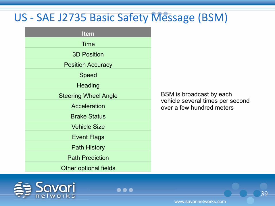
Item Time
3D Position
Position Accuracy
Speed
Heading
Steering Wheel Angle
Acceleration
Brake Status
Vehicle Size
Event Flags
Path History
Path Prediction
Other optional fields
US -‐ SAE J2735 Basic Safety Message (BSM)
BSM is broadcast by each vehicle several times per second over a few hundred meters
39

Current State

Headlines Ø July 2014 – President Obama got a look
at V2X, Federal Highway Administration Research Center, Mc Lean VI
Ø Aug 2014 - NHTSA announces the start of the rule-making process (A-NPRM) for V2V mandate
Ø Oct 2014 – GM CEO “Mary Barra” announces 2017 Cadillac CTS would be the first GM vehicle to carry V2X technology. Partnered with MDOT, UMTRI – 300M investment to explore V2I.
Ø FHWA calls for V2I deployment proposals from various states
41

Summary Ø V2X is a game-changer for safety, because
when enough cars share information about such factors as speed, direction and braking, we’ll be able to reduce crashes dramatically
Ø Infrastructure deployment can improve road congestion & fuel efficiency
Ø Smartphone support will improve the market penetration
Ø Suppliers like Savari who work on V2X are ready to ignite the market
42

Thank You