future atm concepts and evaluation tool (facet) interface
TRANSCRIPT
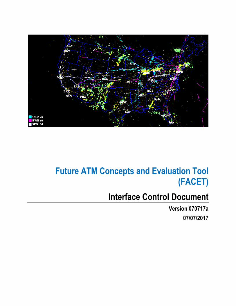
Future ATM Concepts and Evaluation Tool (FACET)
Interface Control Document Version 070717a
07/07/2017

FACET ICD Table of Contents
ICD Version X.X ii Future ATM Concepts and Evaluation Tool (FACET)

FACET ICD Table of Contents
ICD Version X.X iii Future ATM Concepts and Evaluation Tool (FACET)
Table of Contents
1. Purpose of Interface Control .................................................................................... 1
2. Introduction ............................................................................................................... 2
3. Overview .................................................................................................................... 3
4. Detailed Airspace Adaptation Interface Requirements ......................................... 54.1 Requirements for Navigational Aids (NAVAID) .................................................. 5
4.1.1 Assumptions ................................................................................................ 54.1.2 Message Format (or Record Layout) ........................................................... 54.1.3 Sample Messages ....................................................................................... 6
4.2 Requirements for Waypoints .............................................................................. 64.2.1 Assumptions ................................................................................................ 64.2.2 Message Format (or Record Layout) ........................................................... 74.2.3 Sample Messages ....................................................................................... 7
4.3 Requirements for Airways .................................................................................. 74.3.1 Assumptions ................................................................................................ 84.3.2 Message Format (or Record Layout) ........................................................... 84.3.3 Sample Messages ....................................................................................... 8
4.4 Requirements for Airport Locations ................................................................... 94.4.1 Assumptions ................................................................................................ 94.4.2 Message Format (or Record Layout) ......................................................... 104.4.3 Sample Messages ..................................................................................... 10
4.5 Requirements for Flight Information Region (FIR) Description ........................ 104.5.1 Assumptions .............................................................................................. 114.5.2 Message Format (or Record Layout) ......................................................... 114.5.3 Sample Messages ..................................................................................... 12
4.6 Requirements for Sector Description ............................................................... 124.6.1 Assumptions .............................................................................................. 134.6.2 Message Format (or Record Layout) ......................................................... 134.6.3 Sample Messages ..................................................................................... 14
4.7 Requirements for Special Use Airspace (SUA) Descriptions ........................... 154.7.1 Assumptions .............................................................................................. 154.7.2 Message Format (or Record Layout) ......................................................... 164.7.3 Sample Messages ..................................................................................... 17
4.8 Requirements for Sector Capacities ................................................................ 184.8.1 Assumptions .............................................................................................. 184.8.2 Message Format (or Record Layout) ......................................................... 184.8.3 Sample Messages ..................................................................................... 18
4.9 Requirements for Nominal Airport Capacities .................................................. 194.9.1 Assumptions .............................................................................................. 194.9.2 Message Format (or Record Layout) ......................................................... 194.9.3 Sample Messages ..................................................................................... 19
4.10 Requirements for Standard Arrival and Departure Routes .............................. 20
FACET ICD List of Figures
ICD Version X.X iv Future ATM Concepts and Evaluation Tool (FACET)
4.10.1 Assumptions .............................................................................................. 204.10.2 Message Format (or Record Layout) ......................................................... 204.10.3 Sample Messages ..................................................................................... 21
5. Detailed Air Traffic Data Interface Requirements ................................................ 225.1 Requirements for TRX (track) Data Format ..................................................... 22
5.1.1 Assumptions .............................................................................................. 225.1.2 Message Format (or Record Layout) ......................................................... 235.1.3 Sample Messages ..................................................................................... 23
Appendix A: Record of Changes ................................................................................ 25
Appendix B: Acronyms ................................................................................................ 26
List of Figures
Figure 1: Architecture of FACET's routing parsing and trajectory prediction module. ...... 4
List of Tables
Figure 1: Architecture of FACET's routing parsing and trajectory prediction module. ...... 4
Table 1 NAVAID message format .................................................................................... 5
Table 2 NAVAID sample messages ................................................................................. 6
Table 3 Waypoint message format ................................................................................... 7
Table 4 Waypoint sample messages ............................................................................... 7
Table 5 Airway message format ....................................................................................... 8
Table 6 Airway sample messages .................................................................................... 9
Table 7 Airport location message format ........................................................................ 10
Table 8 Airport location sample messages .................................................................... 10
Table 9 FIR/Center message format .............................................................................. 11
Table 10 FIR/Center sample message ........................................................................... 12
Table 11 Sector message format ................................................................................... 14
Table 12 Sector sample message .................................................................................. 14
Table 13 SUA1 message format .................................................................................... 16

FACET ICD List of Tables
ICD Version X.X v Future ATM Concepts and Evaluation Tool (FACET)
Table 14 SUA2 message format .................................................................................... 16
Table 15 SUA3 message format .................................................................................... 16
Table 16 SUA7 message format .................................................................................... 16
Table 17 SUA1 sample message ................................................................................... 17
Table 18 SUA2 sample message ................................................................................... 17
Table 19 SUA3 sample message ................................................................................... 17
Table 20 SUA7 sample messages ................................................................................. 17
Table 21 Sector capacity message format ..................................................................... 18
Table 22 Sector capacity sample messages .................................................................. 18
Table 23 Airport capacity message format ..................................................................... 19
Table 24 Airport capacity sample messages .................................................................. 19
Table 25 Standard arrival and departure route message format .................................... 21
Table 26 Standard departure and arrival route sample message .................................. 21
Table 27 TRACK_TIME message format ....................................................................... 23
Table 28 TRACK message format ................................................................................. 23
Table 29 FP_ROUTE message format .......................................................................... 23
Table 30 TRACK_TIME sample message ..................................................................... 23
Table 31 TRACK sample message ................................................................................ 24
Table 32 FP_ROUTE sample message ......................................................................... 24
Table 33 - Record of Changes ....................................................................................... 25
Table 34 - Acronyms ...................................................................................................... 26
FACET ICD Purpose of Interface Control
ICD Version X.X 1 Future ATM Concepts and Evaluation Tool (FACET)
1. Purpose of Interface Control This Interface Control Document (ICD) documents the airspace adaptation and air traffic inputs of NASA’s Future ATM Concepts and Evaluation Tool (FACET). Its intended audience is the project manager, project team, development team, and stakeholders interested in interfacing with the system. FACET equips Air Traffic Management (ATM) researchers and service providers with a way to explore, develop and evaluate advanced air transportation concepts before they are field-tested and eventually deployed. FACET is a flexible software tool that is capable of quickly generating and analyzing thousands of aircraft trajectories. It provides researchers with a simulation environment for preliminary testing of advanced ATM concepts. Using aircraft performance profiles, airspace models, weather data, and flight schedules, the tool models trajectories for the climb, cruise, and descent phases of flight for each type of aircraft. An advanced graphical interface displays traffic patterns in two and three dimensions, under various current and projected conditions for specific airspace regions or over the entire continental United States. The system is able to simulate a full day’s dynamic national airspace system (NAS) operations, model system uncertainty, measure the impact of different decision-makers in the NAS, and provide analysis of the results in graphical form, including sector, airport, fix, and airway usage statistics. NASA researchers test and analyze the system-wide impact of new traffic flow management algorithms under anticipated air traffic growth projections on the nation’s air traffic system. In addition to modeling the airspace system for NASA research, FACET has also successfully transitioned into a valuable tool for operational use. Federal Aviation Administration (FAA) traffic flow managers and commercial airline dispatchers have used FACET technology for real-time operations planning. FACET integrates live air traffic data from FAA radar systems and weather data from the National Weather Service to summarize NAS performance. This information allows system operators to reroute flights around congested airspace and severe weather to maintain safety and minimize delay. FACET also supports the planning and post-operational evaluation of reroute strategies at the national level to maximize system efficiency. For the commercial airline passenger, strategic planning with FACET can result in fewer flight delays and cancellations. The performance capabilities of FACET are largely due to its architecture, which strikes a balance between flexibility and fidelity. FACET is capable of modeling the airspace operations for the continental United States, processing thousands of aircraft on a single computer. FACET was written in Java and C, enabling the portability of its software to a variety of operating systems. In addition, FACET was designed with a modular software architecture to facilitate rapid prototyping of diverse ATM concepts. Several advanced ATM concepts have already been implemented in FACET, including aircraft self-separation, prediction of aircraft demand and sector congestion, system-wide impact assessment of traffic flow management constraints, and wind-optimal routing. For more information on the Future ATM Concepts Evaluation Tool (FACET), please visit:
www.aviationsystems.arc.nasa.gov.

FACET ICD Introduction
ICD Version X.X 2 Future ATM Concepts and Evaluation Tool (FACET)
2. Introduction This ICD specifies the interface requirements that the airspace adaptations and historical air traffic data archives must meet.
For each interface, the ICD provides the following information:
• A description of the data format • A general description of the data elements • Assumptions where appropriate • Sample data messages

FACET ICD Overview
ICD Version X.X 3 Future ATM Concepts and Evaluation Tool (FACET)
3. Overview Figure 1 illustrates the architecture of the route parsing and trajectory prediction modules in FACET, which are two of the core capabilities of the system. These modules are highlighted in this ICD to provide the reader with insight into how FACET makes use of the airspace adaptation data and the historical air traffic data. The module labeled 31 in Figure 1 provides wind data and information from a route navigation module (33) to determine aircraft heading dynamics, which are received by a heading dynamics module (41). The heading dynamics module optionally includes information on maximum banking angle at one or more altitudes and maximum turn rate at one or more altitudes. The route navigation module (33) receives information from a direct routing module (35) or, alternatively, from a flight plan routing module (37) and provides destination coordinates. An airspace module (39) provides information to a flight option logic module (40) that determines whether the flight is simulated according to direct-to routing or according to flight plan routing or optionally replayed from a historical data archive provided by module 50. Where a flight plan is filed and followed, the flight plan routing module (37) may provide coordinates of one or more waypoints for the flight route. The flight plan and any optional flight plan amendments are obtained from the trafkc flight plan and scheduled data module (50)
An aircraft performance database (44) provides relevant performance information on more than 500 aircraft, optionally including data for each aircraft on maximum airspeed in the absence of wind, fuel consumption at different altitudes, different air speeds and different payload weights, maximum climb rate at one or more altitudes, aircraft weight range (empty to fully loaded), practical maximum flight altitude, and angle of attack at initiation of stall (optional). This information is provided for and used by an aircraft performance module (45) that models a selected aircraft’s performance and in turn, provides airspeed command and performance limits information for an airspeed dynamics module (47). The aircraft performance module (45) also provides altitude command and performance limits information for an altitude kinematics module (49). The airspeed dynamics module (47) provides relevant, processed airspeed and altitude information to the latitude and longitude kinematics command module (43) and to the heading dynamics module (41). The latitude and longitude (LLK) module (43) also receives relevant, processed information from the altitude kinematics module (49) and information on flight path angle. The wind data module (31), the airspace module (39), the aircraft performance module (45), the LLK module (43) provide output information that is received by the graphical user interface.

FACET ICD Overview
ICD Version X.X 4 Future ATM Concepts and Evaluation Tool (FACET)
Figure 1: Architecture of FACET's routing parsing and trajectory prediction module.
This ICD is predominantly focused on describing the airspace database (see module 39) and the track flight plan and schedule data modules (module 50).

FACET ICD Detailed Airspace Adaptation Interface Requirements
ICD Version X.X 5 Future ATM Concepts and Evaluation Tool (FACET)
4. Detailed Airspace Adaptation Interface Requirements This section describes the data fields and formats for the airspace adaptation files required for FACET. Each airspace adaptation element (e.g., Navigational Aid, Waypoint, Airport, etc.) is described in a separate subsection, and each subsection subsequently provides a review of assumptions, data field descriptions and sample data records for clarity.
4.1 Requirements for Navigational Aids (NAVAID) An electronic device on the earth’s surface which provides point to point guidance information or position data to aircraft in flight.
4.1.1 Assumptions
Identifier: Will contain up to four characters specifying the identification assigned to the NAVAID by the controlling authority. Latitude/Longitude: The geographic coordinate location of the NAVAID. The format shall include one letter identifying the hemisphere (N, E, S, W) followed by degrees, minutes and seconds. Decimal degrees will be of length 10 for latitude and length 11 for longitude. Elevation: The elevation, measured in feet, at the base of the antenna from mean sea level. If unknown, “U” shall be entered. Format: ASCII tab delimitated fields. One NAVAID per line.
4.1.2 Message Format (or Record Layout) Table 1 NAVAID message format
Field 1 Identifier
Field 2 N/S hemisphere designator and 2 digit latitude degrees
Field 3 2 digit latitude minutes
Field 4 5 digit latitude seconds
Field 5 W/E hemisphere designator and 2 digit
FACET ICD Detailed Airspace Adaptation Interface Requirements
ICD Version X.X 6 Future ATM Concepts and Evaluation Tool (FACET)
longitude degrees
Field 6 2 digit longitude minutes
Field 7 5 digit longitude seconds
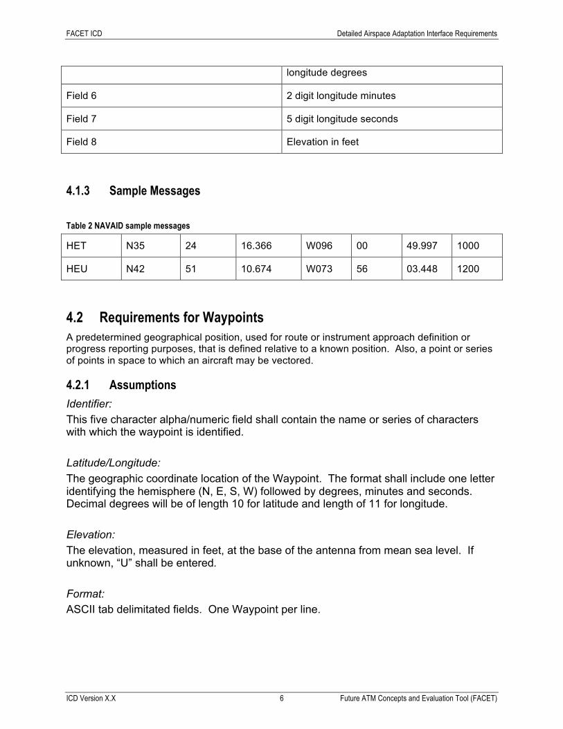
Field 8 Elevation in feet
4.1.3 Sample Messages Table 2 NAVAID sample messages
HET N35 24 16.366 W096 00 49.997 1000
HEU N42 51 10.674 W073 56 03.448 1200
4.2 Requirements for Waypoints A predetermined geographical position, used for route or instrument approach definition or progress reporting purposes, that is defined relative to a known position. Also, a point or series of points in space to which an aircraft may be vectored.
4.2.1 Assumptions
Identifier: This five character alpha/numeric field shall contain the name or series of characters with which the waypoint is identified. Latitude/Longitude: The geographic coordinate location of the Waypoint. The format shall include one letter identifying the hemisphere (N, E, S, W) followed by degrees, minutes and seconds. Decimal degrees will be of length 10 for latitude and length of 11 for longitude. Elevation: The elevation, measured in feet, at the base of the antenna from mean sea level. If unknown, “U” shall be entered. Format: ASCII tab delimitated fields. One Waypoint per line.

FACET ICD Detailed Airspace Adaptation Interface Requirements
ICD Version X.X 7 Future ATM Concepts and Evaluation Tool (FACET)
4.2.2 Message Format (or Record Layout) Table 3 Waypoint message format
Field 1 Identifier
Field 2 N/S hemisphere designator and 2 digit latitude degrees
Field 3 2 digit latitude minutes
Field 4 5 digit latitude seconds
Field 5 W/E hemisphere designator and 2 digit longitude degrees
Field 6 2 digit longitude minutes
Field 7 5 digit longitude seconds
Field 8 Elevation in feet
4.2.3 Sample Messages Table 4 Waypoint sample messages
HETIK N33 05 38.602 W094 57 51.660 1100
HIBOX N32 13 44.152 W080 41 41.449 1500
4.3 Requirements for Airways A specified route designed for channeling the flow of traffic as necessary for the provision of air traffic services (a generic term meaning variously, flight information service, alerting service, air traffic advisory service, air traffic control service, approach control service, etc.).
The two primary types of airways used in FACET are jet routes and victor airways. Jet routes are high altitude airways (from 18,000 ft MSL to FL450) based on VOR stations and are prefixed by the letter “J”. Victor airways are low altitude airways (below 18,000 ft MSL) that are based on VOR stations and are designed with the prefix “V”.
FACET ICD Detailed Airspace Adaptation Interface Requirements
ICD Version X.X 8 Future ATM Concepts and Evaluation Tool (FACET)
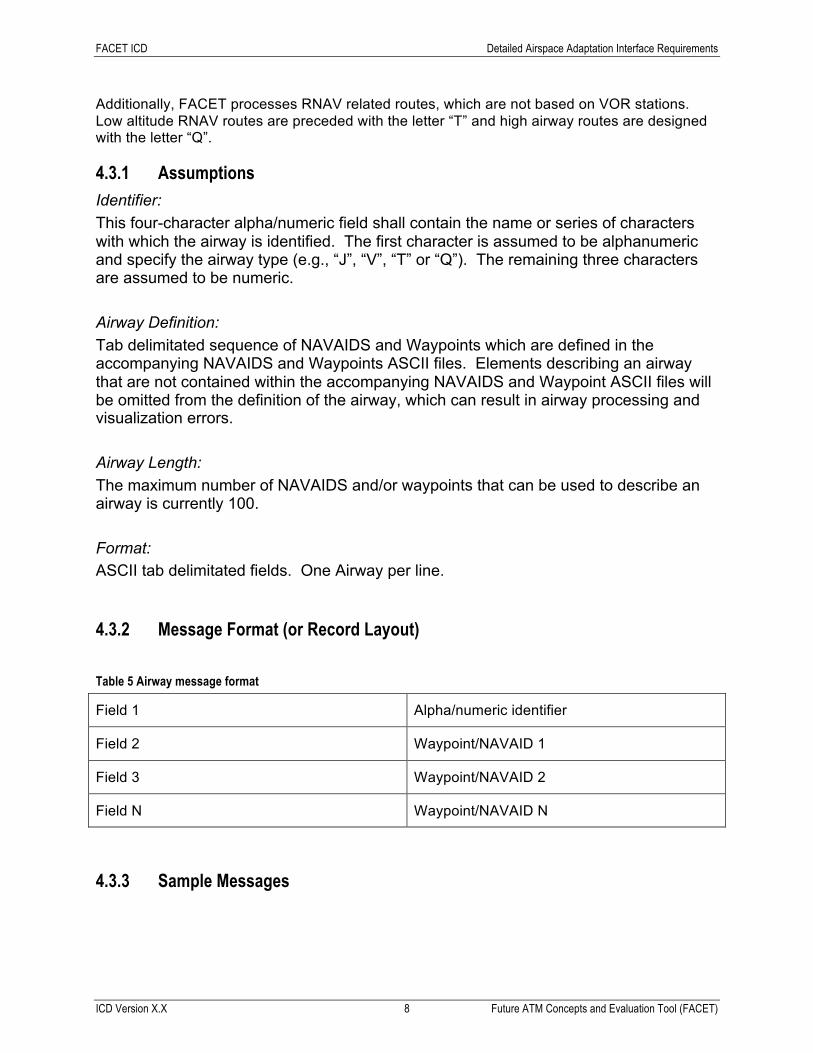
Additionally, FACET processes RNAV related routes, which are not based on VOR stations. Low altitude RNAV routes are preceded with the letter “T” and high airway routes are designed with the letter “Q”.
4.3.1 Assumptions
Identifier: This four-character alpha/numeric field shall contain the name or series of characters with which the airway is identified. The first character is assumed to be alphanumeric and specify the airway type (e.g., “J”, “V”, “T” or “Q”). The remaining three characters are assumed to be numeric. Airway Definition: Tab delimitated sequence of NAVAIDS and Waypoints which are defined in the accompanying NAVAIDS and Waypoints ASCII files. Elements describing an airway that are not contained within the accompanying NAVAIDS and Waypoint ASCII files will be omitted from the definition of the airway, which can result in airway processing and visualization errors. Airway Length: The maximum number of NAVAIDS and/or waypoints that can be used to describe an airway is currently 100. Format: ASCII tab delimitated fields. One Airway per line.
4.3.2 Message Format (or Record Layout) Table 5 Airway message format
Field 1 Alpha/numeric identifier
Field 2 Waypoint/NAVAID 1
Field 3 Waypoint/NAVAID 2
Field N Waypoint/NAVAID N
4.3.3 Sample Messages

FACET ICD Detailed Airspace Adaptation Interface Requirements
ICD Version X.X 9 Future ATM Concepts and Evaluation Tool (FACET)
Table 6 Airway sample messages
J476 YYC ALOMO YEA YQV
J507 BRW SCC FYU ORT BORAN YAK
V111 BSR SNS HENCE CATHE KARNN WINDY PATYY MOD
4.4 Requirements for Airport Locations Airport is defined as an area of land that is used or intended to be used for the landing and take-off of aircraft, and includes its buildings and facilities, if any. The terms "aerodrome" and "airfield" are considered to be synonymous with the term "airport".
4.4.1 Assumptions
Name: The official name for an airport as designated by the operating agency or by official publications of the country in which the air facility is located. Assumed to be alpha/numeric with spaces replaced by underbars (_). Max name length shall not exceed 100 characters Unique Identifier: Will contain up to four characters specifying the unique identification assigned to the Airport by the controlling authority. Latitude/Longitude: The geographic coordinate location of the Airport. The format shall include one letter identifying the hemisphere (N, E, S, W) followed by degrees, minutes and seconds. Decimal degrees will be of length 9 for latitude and length of 10 for longitude. Elevation: The highest point of an airport’s usable runways measured in feet from Mean Sea Level. Format: ASCII tab delimitated fields. One Airport per line.

FACET ICD Detailed Airspace Adaptation Interface Requirements
ICD Version X.X 10 Future ATM Concepts and Evaluation Tool (FACET)
4.4.2 Message Format (or Record Layout) Table 7 Airport location message format
Field 1 Name
Field 2 Identifier
Field 3 N/S hemisphere designator and 2 digit latitude degrees
Field 4 2 digit latitude minutes
Field 5 4 digit latitude seconds
Field 6 W/E hemisphere designator and 2 digit longitude degrees
Field 7 2 digit longitude minutes
Field 8 4 digit longitude seconds
Field 9 Elevation in feet
4.4.3 Sample Messages Table 8 Airport location sample messages
SAN_FRANCISCO_INTERN_CA KSFO N37 37 08.40 W122 22 29.40 13
SLEETMUTE_AK KSLQ N61 42 33.50 W095 37 16.02 489
HUNTER_AAF_GA KSVN N32 00 34.70 W081 08 44.40 42
4.5 Requirements for Flight Information Region (FIR) Description Designated airspace within which some or all aircraft may be subject to air traffic control. For United States operations, the FIR is defined in terms of a collection of Centers. A Center typically accepts traffic from and ultimately passes traffic to the control of a Terminal Control Center or another Center. The Center is subsequently subdivided into smaller regions of airspace referred to as Sectors, which are defined in the next section.

FACET ICD Detailed Airspace Adaptation Interface Requirements
ICD Version X.X 11 Future ATM Concepts and Evaluation Tool (FACET)
4.5.1 Assumptions
Name: The official name assigned to the specific airspace boundary by the controlling authority. Assumed to be alpha/numeric with spaces replaced by underbars (_). Max name length shall not exceed 100 characters Unique Identifier: Will contain up to four characters specifying the unique identification assigned to the FIR/Center by the controlling authority. Latitude/Longitude: A series of latitude/longitude coordinates describing the polygon bounding the FIR/Center. The format shall include one letter identifying the hemisphere (N, E, S, W) followed by degrees, minutes and seconds. Decimal degrees will be of length 9 for latitude and length of 10 for longitude. Upper Effective Altitude: The highest altitude (ceiling) Above Mean Sea Level (AMSL) in feet for the upper vertical limit of the given airspace. Lower Effective Altitude: The lower altitude (floor) Above Mean Sea Level (AMSL) in feet for the lower vertical limit of the given airspace. Format: ASCII tab delimitated fields.
4.5.2 Message Format (or Record Layout) Table 9 FIR/Center message format
Field 1 Name
Field 2 Identifier
Field 3 Lower Effective Altitude
Field 4 Upper Effective Altitude
Field 5 N/S hemisphere designator and 2 digit latitude degrees for the 1st point describing the

FACET ICD Detailed Airspace Adaptation Interface Requirements
ICD Version X.X 12 Future ATM Concepts and Evaluation Tool (FACET)
FIR/Center
Field 6 2 digit latitude minutes or the 1st point describing the FIR/Center
Field 7 4 digit latitude seconds or the 1st point describing the FIR/Center
Field 8 W/E hemisphere designator and 2 digit longitude degrees or the 1st point describing the FIR/Center
Field 9 2 digit longitude minutes or the 1st point describing the FIR/Center
Field 10 4 digit longitude seconds or the 1st point describing the FIR/Center
Field 11 through Field N Remaining latitude/longitude points describing the FIR/Center
4.5.3 Sample Messages Table 10 FIR/Center sample message
Albuquerque_Center
ZAB
0 450000
N36 43 00.00 W105 20 30.00
N36 43 00.00 W105 00 00.00
N37 18 30.00 W103 09 00.00
N37 30 00.00 W102 33 30.00
N37 30 00.00 W102 33 00.00
4.6 Requirements for Sector Description For air traffic operations in the United States, Centers (see above) are subsequently subdivided into smaller volumes of airspace referred to as sectors. Sectors use distinct radio frequencies
FACET ICD Detailed Airspace Adaptation Interface Requirements
ICD Version X.X 13 Future ATM Concepts and Evaluation Tool (FACET)
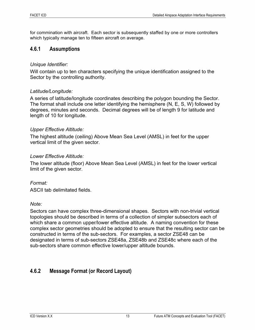
for commination with aircraft. Each sector is subsequently staffed by one or more controllers which typically manage ten to fifteen aircraft on average.
4.6.1 Assumptions
Unique Identifier: Will contain up to ten characters specifying the unique identification assigned to the Sector by the controlling authority. Latitude/Longitude: A series of latitude/longitude coordinates describing the polygon bounding the Sector. The format shall include one letter identifying the hemisphere (N, E, S, W) followed by degrees, minutes and seconds. Decimal degrees will be of length 9 for latitude and length of 10 for longitude. Upper Effective Altitude: The highest altitude (ceiling) Above Mean Sea Level (AMSL) in feet for the upper vertical limit of the given sector. Lower Effective Altitude: The lower altitude (floor) Above Mean Sea Level (AMSL) in feet for the lower vertical limit of the given sector. Format: ASCII tab delimitated fields. Note: Sectors can have complex three-dimensional shapes. Sectors with non-trivial vertical topologies should be described in terms of a collection of simpler subsectors each of which share a common upper/lower effective altitude. A naming convention for these complex sector geometries should be adopted to ensure that the resulting sector can be constructed in terms of the sub-sectors. For examples, a sector ZSE48 can be designated in terms of sub-sectors ZSE48a, ZSE48b and ZSE48c where each of the sub-sectors share common effective lower/upper altitude bounds.
4.6.2 Message Format (or Record Layout)

FACET ICD Detailed Airspace Adaptation Interface Requirements
ICD Version X.X 14 Future ATM Concepts and Evaluation Tool (FACET)
Table 11 Sector message format
Field 1 Identifier
Field 2 Lower Effective Altitude
Field 3 Upper Effective Altitude
Field 4 N/S hemisphere designator and 2 digit latitude degrees for the 1st point describing the sector
Field 5 2 digit latitude minutes or the 1st point describing the sector
Field 6 4 digit latitude seconds or the 1st point describing the sector
Field 7 W/E hemisphere designator and 2 digit longitude degrees or the 1st point describing the sector
Field 8 2 digit longitude minutes or the 1st point describing the sector
Field 9 4 digit longitude seconds or the 1st point describing the sector
Field 10 through Field N Remaining latitude/longitude points describing the sector
4.6.3 Sample Messages Table 12 Sector sample message
ZAB
24000 60000
N47 01 18.33 W105 54 27.86
N46 43 05.56 W105 30 19.41
N47 28 11.11 W103 44 20.44
N47 30 22.21 W102 33 30.00
N47 30 00.00 W102 33 00.00

FACET ICD Detailed Airspace Adaptation Interface Requirements
ICD Version X.X 15 Future ATM Concepts and Evaluation Tool (FACET)
4.7 Requirements for Special Use Airspace (SUA) Descriptions A Special Use Airspace is an area in which air traffic operations may be limited for flights not specifically participating in the operations associated with this region of airspace. Often these operations are of a military nature.
4.7.1 Assumptions
A complete SUA consists of the following three individual types of records: • SUA1: the records associated with this data block contains the SUA type, name,
location and State • SUA2: contains the active start and stop times for the SUA • SUA3: upper and lower effective altitudes of the SUA • SUA7: contains the latitude/longitude coordinates of the SUA
Unique Identifier: Will contain up to ten characters specifying the unique identification assigned to the Sector by the controlling authority. SUA Types: Can be one of the following: “ALERT”, “MILITARY”, “PROHIBITED”, “RESTRICTED”, “WARNING” or “USER” Effective Times: Can be one of the following: start/stop times in HHMMZ-HHMMZ format, “CONTINUOUS”, “SR-SS” (sunrise to sunset) or “INTERMITTENTLY”. Latitude/Longitude: A series of latitude/longitude coordinates describing the polygon bounding the Sector. The format shall include a one letter identifying the hemisphere (N, E, S, W) followed by degrees, minutes and seconds. Decimal degrees will be of length 9 for latitude and length of 10 for longitude. Upper Effective Altitude: The highest altitude (ceiling) Above Mean Sea Level (AMSL) in feet for the upper vertical limit of the given sector. Lower Effective Altitude:

FACET ICD Detailed Airspace Adaptation Interface Requirements
ICD Version X.X 16 Future ATM Concepts and Evaluation Tool (FACET)
The lower altitude (floor) Above Mean Sea Level (AMSL) in feet for the lower vertical limit of the given sector. Format: ASCII tab delimitated fields. The SUA1, SUA2, SUA3 and SUA7 fields are on separate lines. One SUA7 record is provided for each latitude/longitude pair comprising the SUA boundary.
4.7.2 Message Format (or Record Layout)
Table 13 SUA1 message format
Field 1 “SUA1” followed by SUA type
Field 2 Name
Field 3 Location (typically a city or military installation)
Field 4 Location (State)
Table 14 SUA2 message format
Field 1 “SUA2” followed by SUA type
Field 2 Name
Field 3 start/stop times in HHMMZ-HHMMZ format, “CONTINUOUS”, “SR-SS” (sunrise to sunset) or “INTERMITTENTLY”
Table 15 SUA3 message format
Field 1 “SUA3” followed by SUA type
Field 2 Name
Field 3 Lower Effective Altitude (ft)
Field 4 Upper Effective Altitude (ft)
Table 16 SUA7 message format
Field 1 “SUA7” followed by SUA type

FACET ICD Detailed Airspace Adaptation Interface Requirements
ICD Version X.X 17 Future ATM Concepts and Evaluation Tool (FACET)
Field 2 Name
Field 5 2 digit latitude minutes or the 1st point describing the sector
Field 6 4 digit latitude seconds or the 1st point describing the sector
Field 7 W/E hemisphere designator and 2 digit longitude degrees or the 1st point describing the sector
Field 8 2 digit longitude minutes or the 1st point describing the sector
Field 9 4 digit longitude seconds or the 1st point describing the sector
4.7.3 Sample Messages Table 17 SUA1 sample message
SUA1ALERT 211 Moffett Field
CA
Table 18 SUA2 sample message
SUA2ALERT 211 0800Z-2000Z
Table 19 SUA3 sample message
SUA3ALERT 211 SURFACE to 4500’
Table 20 SUA7 sample messages
SUA7ALERT 211 N47 01 18.33 W105 54 27.86

FACET ICD Detailed Airspace Adaptation Interface Requirements
ICD Version X.X 18 Future ATM Concepts and Evaluation Tool (FACET)
SUA7ALERT 211 N46 43 05.56 W105 30 19.41
SUA7ALERT 211 N47 30 22.21 W102 33 30.00
SUA7ALERT 211 N47 30 00.00 W102 33 00.00
4.8 Requirements for Sector Capacities Nominal capacity for a sector which establishes a numerical trigger to provide notification to facility personnel that sector efficiency may be degraded during specific periods of time due to potentially high controller workload
4.8.1 Assumptions
Unique Identifier: Will contain up to four characters specifying the unique identification assigned to the sector by the controlling authority. Capacity: Number of unique aircraft observed in a sector over a 15-minute time horizon. Format: ASCII tab delimitated fields. One sector capacity per line.
4.8.2 Message Format (or Record Layout) Table 21 Sector capacity message format
Field 1 Sector Name
Field 2 Capacity
4.8.3 Sample Messages Table 22 Sector capacity sample messages
ZAB49 12
ZAB47 18

FACET ICD Detailed Airspace Adaptation Interface Requirements
ICD Version X.X 19 Future ATM Concepts and Evaluation Tool (FACET)
ZAB17 18
4.9 Requirements for Nominal Airport Capacities Nominal capacity for an airport under the predominant configuration under good weather conditions which establishes a numerical trigger to provide notification to facility personnel that airport efficiency may be degraded during specific periods of time due to potentially high controller workload.
4.9.1 Assumptions
Unique Identifier: Will contain up to four characters specifying the unique identification assigned to the airport by the controlling authority. Capacity: Number of unique aircraft landing and departing at an airport over a 15-minute time horizon. Format: ASCII tab delimitated fields. One airport capacity per line.
4.9.2 Message Format (or Record Layout) Table 23 Airport capacity message format
Field 1 Airport Identifier
Field 2 Departure Capacity
Field 3 Arrival Capacity
4.9.3 Sample Messages Table 24 Airport capacity sample messages
KORD 55 20
FACET ICD Detailed Airspace Adaptation Interface Requirements
ICD Version X.X 20 Future ATM Concepts and Evaluation Tool (FACET)
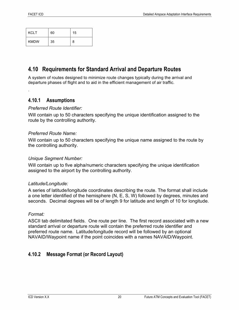
KCLT 60 15
KMDW 35 8
4.10 Requirements for Standard Arrival and Departure Routes A system of routes designed to minimize route changes typically during the arrival and departure phases of flight and to aid in the efficient management of air traffic.
.
4.10.1 Assumptions Preferred Route Identifier: Will contain up to 50 characters specifying the unique identification assigned to the route by the controlling authority. Preferred Route Name: Will contain up to 50 characters specifying the unique name assigned to the route by the controlling authority. Unique Segment Number: Will contain up to five alpha/numeric characters specifying the unique identification assigned to the airport by the controlling authority. Latitude/Longitude: A series of latitude/longitude coordinates describing the route. The format shall include a one letter identified of the hemisphere (N, E, S, W) followed by degrees, minutes and seconds. Decimal degrees will be of length 9 for latitude and length of 10 for longitude. Format: ASCII tab delimitated fields. One route per line. The first record associated with a new standard arrival or departure route will contain the preferred route identifier and preferred route name. Latitude/longitude record will be followed by an optional NAVAID/Waypoint name if the point coincides with a names NAVAID/Waypoint.
4.10.2 Message Format (or Record Layout)

FACET ICD Detailed Airspace Adaptation Interface Requirements
ICD Version X.X 21 Future ATM Concepts and Evaluation Tool (FACET)
Table 25 Standard arrival and departure route message format
Field 1 Alpha/numeric identifier
Field 2 Latitude
Field 3 Longitude
Field 4 Route identifier if first record for a new route
Field 5 Route name if first record for a new route
4.10.3 Sample Messages Table 26 Standard departure and arrival route sample message
S0005 N40 57 16.00 W082 28 39.90 ABERZ.ABEERZ1 ABERZ ONE
S0005 N41 17 38.08 W082 01 42.20 JAKEE
S0005 N41 24 42.00 W081 50 59.20 CLE

FACET ICD Detailed Air Traffic Data Interface Requirements
ICD Version X.X 22 Future ATM Concepts and Evaluation Tool (FACET)
5. Detailed Air Traffic Data Interface Requirements This section describes FACET’s TRX (track) data format, which contains historical position and flight plan information for a collection of flights. This file contains three predominant message types: TRACK_TIME, TRACK and FP_ROUTE. A brief description of the content of each of these messages follows:
• TRACK_TIME: Unix epoch (or Unix time or POSIX time or Unix timestamp), which is the number of seconds that have elapsed since January 1, 1970 (midnight UTC/GMT)
• TRACK: contains the unique aircraft identifier, aircraft type, current latitude/longitude position, ground speed, flight level, heading, current FIR/Center, current sector (optional)
• FP_ROUTE: current filed/flown flight plan which reflects any flight plan amendments
5.1 Requirements for TRX (track) Data Format
5.1.1 Assumptions Time Stamp: Unix epoch (or Unix time or POSIX time or Unix timestamp), which is the number of seconds that have elapsed since January 1, 1970 (midnight UTC/GMT) Latitude/Longitude: The geographic coordinate location of the aircraft. The format shall assume a North and West hemisphere convention when specifying the coordinates. Latitude is specified by six characters (DDMMSS) and longitude by seven character (DDDMMSS). Flight Level: Aircraft’s current vertical altitude at standard pressure expressed in hundreds of feet. Ground Speed: Aircraft’s current ground speed in knots. Heading: Aircraft’s current heading in degrees. Format: ASCII tab delimitated fields. TRACK_TIME, TRACK and FP_ROUTE specified on separate lines. Note: TRACK_TIME message is followed by the TRACK and FP_ROUTE messages for all known flights at this time.

FACET ICD Detailed Air Traffic Data Interface Requirements
ICD Version X.X 23 Future ATM Concepts and Evaluation Tool (FACET)
5.1.2 Message Format (or Record Layout) Table 27 TRACK_TIME message format
Field 1 “TRACK_TIME”
Field 2 Unix epoch time in seconds
Table 28 TRACK message format
Field 1 “TRACK”
Field 2 Aircraft identifier
Field 3 Aircraft type
Field 4 Current latitude (DDMMSS)
Field 5 Current longitude (DDDMMSS)
Field 6 Current Ground Speed (kts)
Field 7 Current Flight Level
Field 8 Current Heading (deg)
Field 9 Current Center/FIR
Field 10 Current Sector (optional)
Table 29 FP_ROUTE message format
Field 1 “FP_ROUTE”
Field 2 Flight Plan String
5.1.3 Sample Messages Table 30 TRACK_TIME sample message
TRACK_TIME 1124841777
FACET ICD Detailed Air Traffic Data Interface Requirements
ICD Version X.X 24 Future ATM Concepts and Evaluation Tool (FACET)
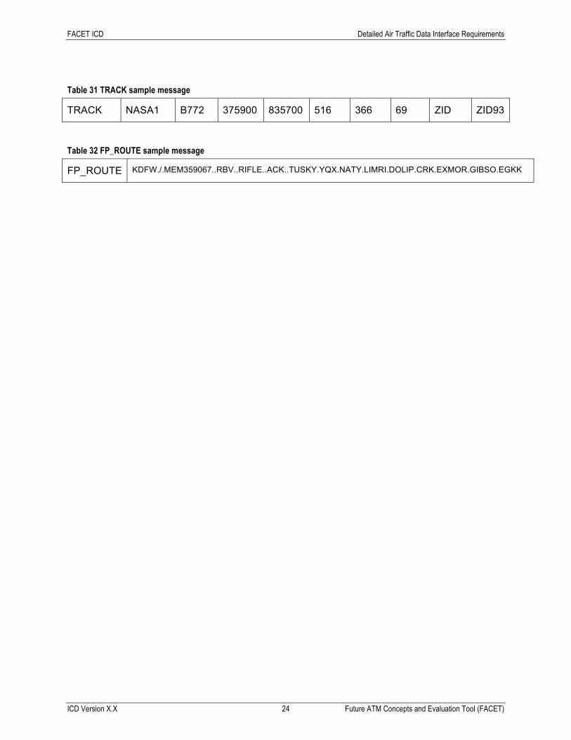
Table 31 TRACK sample message
TRACK NASA1 B772 375900 835700 516 366 69 ZID ZID93
Table 32 FP_ROUTE sample message
FP_ROUTE KDFW./.MEM359067..RBV..RIFLE..ACK..TUSKY.YQX.NATY.LIMRI.DOLIP.CRK.EXMOR.GIBSO.EGKK

CMS XLC Appendix A: Record of Changes
ICD Version X.X 25 <Project and release name>
Appendix A: Record of Changes
Table 33 - Record of Changes
Version Number Date Author/Owner Description of Change
0.1 07/01/2017 S. Grabbe Initial version

CMS XLC Appendix B: Acronyms
ICD Version X.X 26 <Project and release name>
Appendix B: Acronyms
Table 34 - Acronyms
Acronym Literal Translation
ATM Air Traffic Management
FACET Future ATM Concepts and Evaluation Tool
FIR Flight Information Region
FL Flight level
MSL Mean Sea Level
NAS National Airspace System
NAVAID Navigational Aid
SUA Special Use Airspace
TRX Track