fusion of road surface using rgb-d sensorsweb.lums.edu.pk/~akn/files/other/teaching/mobile...
TRANSCRIPT
Fusion of Road Surface using RGB-D SensorsAnsir Ilyas, Muhammad Abdullah
1 Department of Electrical EngineeringSBA School of Science & Engineering – LUMS, Pakistan
{14060038,14060024}@lums.edu.pk
1. IntroductionRoads undergo rapid deterioration due to various economic, social and natural reasons.The uncertainty and unavailability of road safety information has become a major issuein reliably transporting goods, movement of heavy machinery, transport of people andmaterials to/from disaster areas and in even giving plain guarantees for safe traversabilityof a road that is good on paper. Given a starting location and destination, a desktopor mobile mapping service provides a path that any typical vehicle might take. Thesevehicles does not return any exact answer for any particular type of vehicle. Nor do theyreport the relative difficulties that a driver may face while traversing the path. In this reportwe try to use use vision base techniques to detect the negative obstacles of particular roadpatch.
Intelligent navigation and path planning requires some sensors which provide informationof surroundings. Based on this information decision is taken or a parameter is updated likebuilding a map, localization or planning a path. Since, each sensor has some limitationsand inherent uncertainty in sensor readings which may accumulate over time and resultingin erroneous decisions. Sensor fusion is one of the techniques to reduce this error in thereadings and overcome the limitation of sensors by utilizing multiple sensors. Thesesensors can be of same type or different sensors can also be used to complement theinformation of each other. Multisensor data fusion is a process to combine the informationfrom number of different sensors to provide a robust and complete information about theenvironment.
In this project, data fusion is used to detect obstacles on the road and get their accuratelocation. We will also analyze the accuracy of different sensors. The different sensors wewill use are Kinect vision sensor, laser hokuyo sensor to detect the obstacle and GPS andIMU modules to measure their position.
2. Related WorkSeveral approaches have been presented for 3D environment reconstruction, using dif-ferent sensors (cameras, stereo cameras, multiple 2D LRF, 3D LRF, and combinationsof them). For example, (Diebel et al., 2004) use active stereo vision for building a 3Dmetric map of the environment, (Thrun et al., 2004, Fruh, 2004) use two orthogonal 2DLRF to build 3D maps of indoor and outdoor environments, while (Nuchter et al., 2005)use a 2D LRF mounted on a tilt unit that is able to acquire a very precise 3D scan ofthe environment with a relative cheap sensor, but it requires a higher acquisition time dueto the rotation of the laser. approaches based on feature extraction and computer visiontechniques have been proposed (e.g., MonoSLAM (Davison et al., 2007)), providing for3D feature-based maps. Outdoor mapping has also been investigated. For example, in
(Konolige et al., 2006) the use of stereo vision and visual odometry has been proposed forlong distances outdoor navigation of a mobile robot. All these approaches are focused onbuilding metric or feature based maps, either considering relative small environments tomap or focussing on the navigation capabilities of an autonomous platform.[1]
3. Approach
Previously traversability index is calculated using Kinect only. It has a limited rangeand fails in presence of day light due to interference of infrared rays from sun. To caterthis limitation we use long range laser sensor with Kinect and Inertial Measurement Unit(IMU) incrementally calculated vehicle position and orientation.
As mentioned earlier, we are using Kinect XBOX 360, laser scanner and IMU for gettinginformation of road surface. To acquire data from these sensors we need to configure andsimultaneously run all these sensors. Kinect and laser scanner are directly configurablewith ROS. However, we need an IMU that could also directly configured with ROS. Initi-ally we decided to use IMU of our mobile device which transmits data on UDP stream inCSV format. We wrote a code for Socket programming that could receive UDP data on aport. Decoding this data and populating the /imu topic was cumbersome so we decided touse ardrone to IMU data from it.
3.1. Hardware Platform
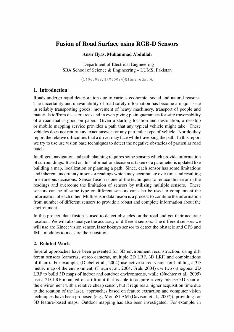
The testing was done on the platform shown in Fig. 1. For initial testing we recorded abagfile of the corridor of electrical engineering department by placing small obstacles asshown below in Fig. 2.
Figura 1. Initial platform used
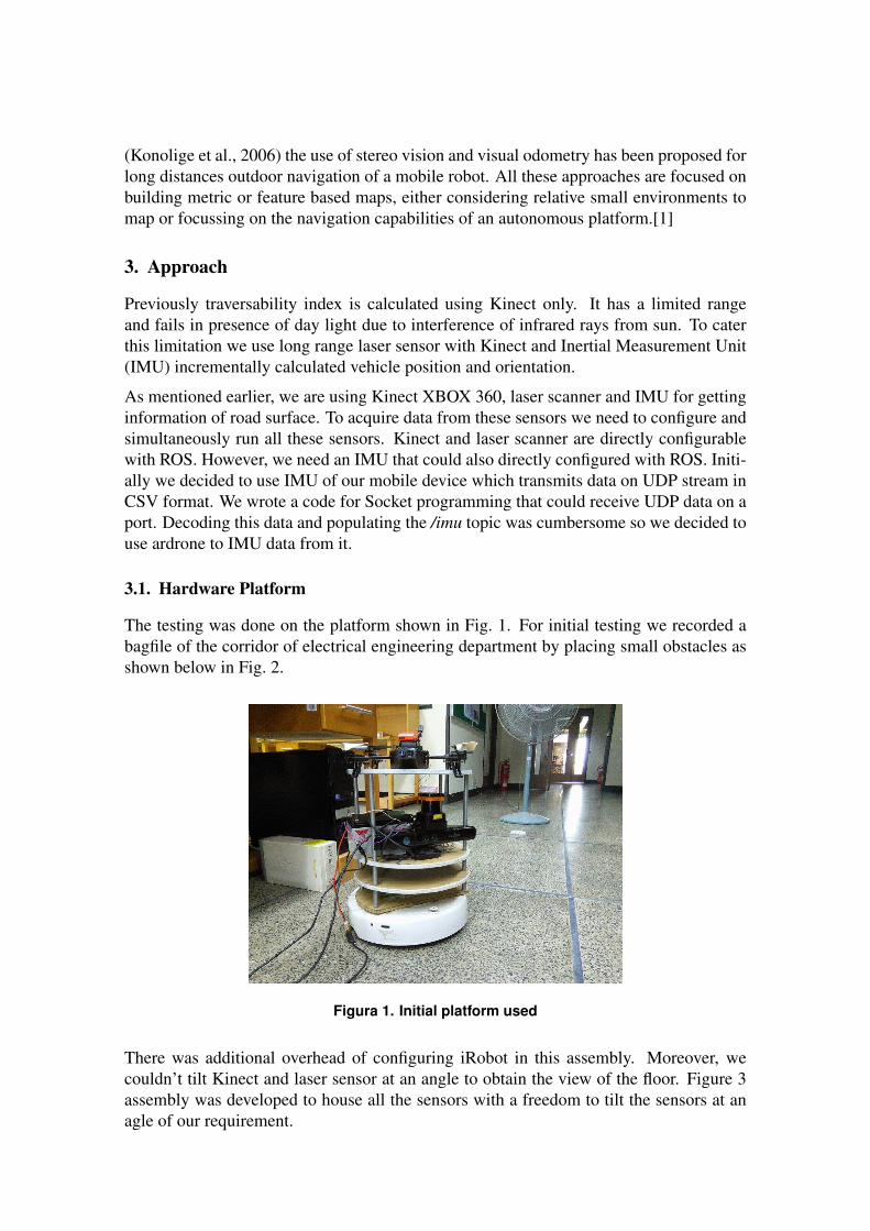
There was additional overhead of configuring iRobot in this assembly. Moreover, wecouldn’t tilt Kinect and laser sensor at an angle to obtain the view of the floor. Figure 3assembly was developed to house all the sensors with a freedom to tilt the sensors at anagle of our requirement.

Figura 2. Bag recorded for test by placing obstacles in corridor
3.2. Sensor Configuration
Next step is to configure these sensors. Laser hokuyo was configured by running ho-kuyo node. Similarly, kinect was configured by executing openni.launch file from thepackage openni launch. These two sensors provide us the depth information but in diffe-rent formats. Laser scanner provides accurate 2D depth information and Kinect gives 3Dpoint cloud. Ardrone was also configured to get imu data.
3.3. Recording Bagfile
For offline processing we need to record data in a bagfile. When the data was recor-ded using the -a option it exceeded the limit and initial data started to drop. Afterlittle exploration it was observed that setting a parameter depth registration false du-ring the recording and changing it to true when playing the bag processes the genera-tes the a point cloud offline. camera/depth/image raw and camera/depth/camera infoare the topics required for XYZ-only point clouds. However, for RGB pointclouds camera/depth registered/image raw, camera/depth registered/camera info, ca-mera/rgb/image raw and camera/rgb/camera info are the required topics. We have re-corded two different bags to process point clouds in both formats.
(a) (b)
Figura 3. New platform with different sensors used
3.4. Publishing Static Transforms
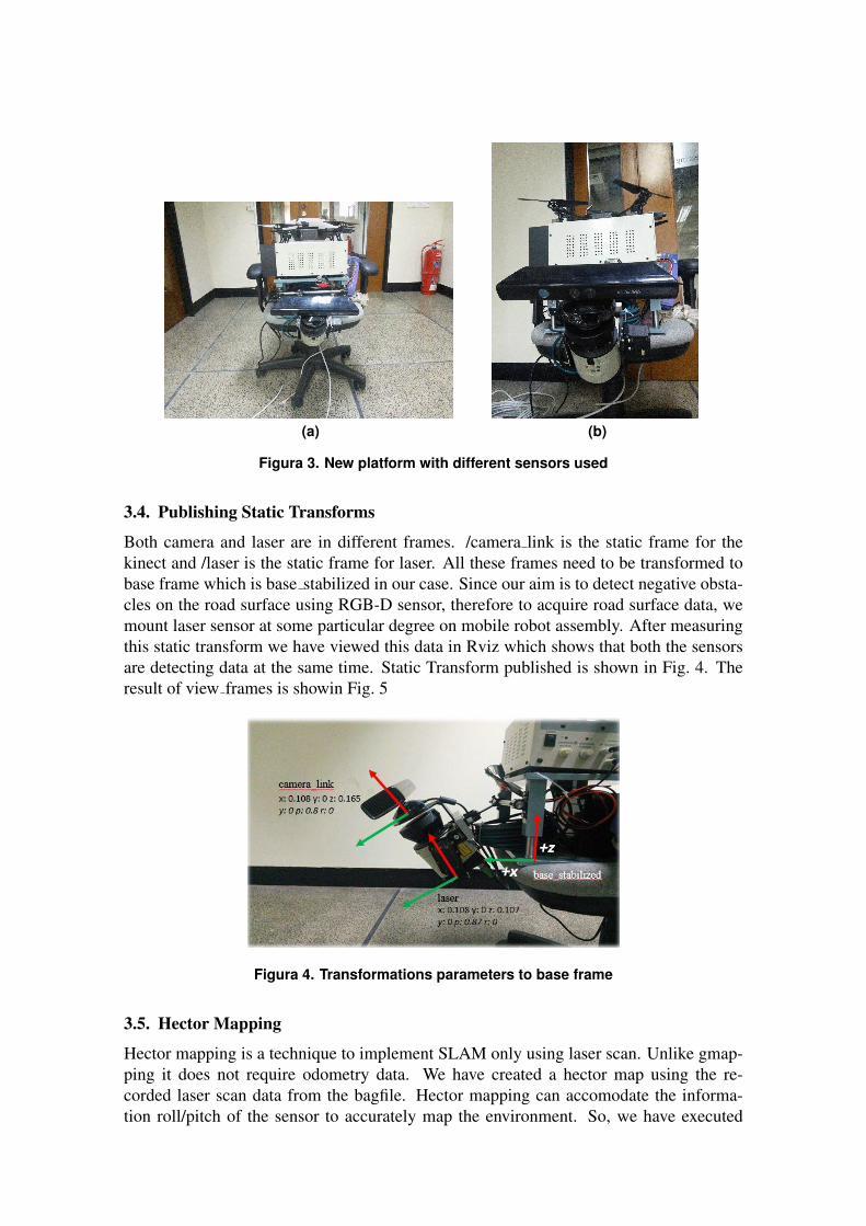
Both camera and laser are in different frames. /camera link is the static frame for thekinect and /laser is the static frame for laser. All these frames need to be transformed tobase frame which is base stabilized in our case. Since our aim is to detect negative obsta-cles on the road surface using RGB-D sensor, therefore to acquire road surface data, wemount laser sensor at some particular degree on mobile robot assembly. After measuringthis static transform we have viewed this data in Rviz which shows that both the sensorsare detecting data at the same time. Static Transform published is shown in Fig. 4. Theresult of view frames is showin Fig. 5
Figura 4. Transformations parameters to base frame
3.5. Hector Mapping
Hector mapping is a technique to implement SLAM only using laser scan. Unlike gmap-ping it does not require odometry data. We have created a hector map using the re-corded laser scan data from the bagfile. Hector mapping can accomodate the informa-tion roll/pitch of the sensor to accurately map the environment. So, we have executed

view_frames Result
base_stabilized
camera_link
Broadcaster: /static_transform_publisher_1431497546010150115Average rate: 98.987 Hz
Most recent transform: 1431497681.602 ( -0.004 sec old)Buffer length: 4.930 sec
ardrone_base_link
Broadcaster: /static_transform_publisher_1431497664669967443Average rate: 98.920 Hz
Most recent transform: 1431497681.605 ( -0.007 sec old)Buffer length: 4.933 sec
laser
Broadcaster: /static_transform_publisher_1431497388963622722Average rate: 98.922 Hz
Most recent transform: 1431497681.598 ( -0.000 sec old)Buffer length: 4.923 sec
Recorded at time: 1431497681.597
Figura 5. Transformations parameters to base frame
imu attitude to tf node which takes care of it. Transformation required for hector map-ping are shown in Fig. 6 and view frames result is shown in Fig. 7
Figura 6. Transformations required for hector mappingview_frames Result
base_stabilized
ardrone_base_link
Broadcaster: /static_transform_publisher_1431497664669967443Average rate: 99.080 Hz
Most recent transform: 1431504961.408 ( -525.427 sec old)Buffer length: 4.945 sec
camera_link
Broadcaster: /static_transform_publisher_1431497546010150115Average rate: 99.066 Hz
Most recent transform: 1431504961.400 ( -525.419 sec old)Buffer length: 4.936 sec
laser
Broadcaster: /base_link_laser_broadcasterAverage rate: 10.120 Hz
Most recent transform: 1431504436.071 ( -0.090 sec old)Buffer length: 4.842 sec
map
Broadcaster: /hector_mappingAverage rate: 34.276 Hz
Most recent transform: 1431504436.021 ( -0.039 sec old)Buffer length: 5.047 sec
scanmatcher_frame
Broadcaster: /hector_mappingAverage rate: 25.266 Hz
Most recent transform: 1431504435.881 ( 0.100 sec old)Buffer length: 4.908 sec
Recorded at time: 1431504435.981
Figura 7. Transformations required for hector mapping
4. Fusion of DataData fusion of laser scanner and kinect would greatly improve the quality of our data andreduce the amount of outliers. After fusion data is used to detect negative obstacles onthe road surface and this information can be translated to road traversibility index (RTI).We use a map created by laser to detect the obstacles. For a transparent object laser scangives incorrect scan. In such scenario, information from Kinect can be used to accountfor this error.
4.1. Fusion using Hector map
We acquire the data of particular patch of road from Kinect and laser. Kinect gives us3D point cloud and laser scan give us 2D line. In order to fuse Kinect point cloud and

laser scan line first we need some 2D map. There are several techniques available formapping such as gmapping and hector mapping. We have created a map using hectormap as we currently don’t have the information of odometry and hector map is built usinglaser scanner data only. Next step after acquiring 2D map and 3D point cloud is to findand match corresponding points align the information of these two sensors.
The requirement for generating hector map is that laser scanner should be parallelto base frame. However, the requirement of our project is to tilt this sensor at a certainangle from the base frame due to which hector map could not be generated successfully.So, a different method for fusion was required.
4.2. Fusion using Line Extraction
In this case, after acquiring the 3D point cloud from Kinect and laser scanner we try toextract the line at same depth as the laser scanner looking towards the road surface asshown in Fig. 8. Then we fuse these lines to improve the quality of our data and reduceoutliers.
Figura 8. Line extraction from point cloud
5. Experiment & Analysis
After initializing all the setup we started Rviz to visualize the data of laser scan. Since allthe transformation have been published, we need to specify the based stabilized frame infixed frame in Rviz as shown in Fig. 9
Looking at the point cloud in Fig. 10 we can observe the obstacles.
By visualizing both the sensors at the same time in Rviz we confirm that the obstacleappears in the frame of camera and sensor occur at same time as shown in Fig. 11
Hector map visualizations is also given in the Fig. 12 below

Figura 9. Laser scan after transformation
Figura 10. RGB point cloud after transformation
6. Conclusions & Future WorkWe have performed an initial setup for recording data and transforming data to the sameframe. Now, using different techniques of line extraction and plane extraction from 2dmap and 3d point cloud could be matched to construct a complete 3D map of the envio-ronment.
7. References[1] Building 3D maps with semantic elements integrating 2D laser, stereo vision and IMUon a mobile robot, Iocchi and Pellegrini
[2] Vehicle specific traversibilty analysis of pathways, Muhammad Mudassir Khan

Figura 11. Fusing information from both sensors
Figura 12. Hector map of corridor