fuse shneider
TRANSCRIPT
l
ME
TS
YS-
ES
UF
LA
CIR
DNI
LY
C
2007
CYLINDRICAL FUSE -SYSTEM status 12/2007
CYLINDRICAL FUSE-SYSTEM
EUROFUSE®
NH-FUSE MATERIAL
MULTIBLOC®
MULTIVERT®
BSL
D/D0-FUSE-SYSTEM
MULTIFIX® 60
MINIATURE FUSE LINKS
HIGH VOLTAGE FUSE LINKS
Content
status 12/2007 CYLINDRICAL FUSE -SYSTEM
3
Cylindrical fuse-system 4–6
Product presentation 4
Characteristics and function 5
Application 6
Cylindrical fuse links 6–12
Specification 6
Assembling 6
Characteristics 7
Technical data 8
Technical standard 8
Advantages 9
Colour system for rated currents 11
Dimensions 12
Cylindrical fuse links „gG“ 13–20
Production programme Cylindrical fuse links „gG“ 13–16
Time/current characteristics Cylindrical fuse links „gG“, size 00 17
Time/current characteristics Cylindrical fuse links „gG“, size 0 17
Time/current characteristics Cylindrical fuse links „gG“, size 1 18
Time/current characteristics Cylindrical fuse links „gG“, size 2 18
Current limiting diagram „gG“ 19
Power dissipation Pn „gG“ 20
Cylindrical fuse links „aM“ 21–27
Production programme Cylindrical fuse links „aM“ 21–23
Time/current characteristics Cylindrical fuse links „aM“, size 0 24
Time/current characteristics Cylindrical fuse links „aM“, size1 24
Time/current characteristics Cylindrical fuse links „aM“, size 2 25
Current limiting diagram „aM“ 26
Power dissipation Pn „aM“ 27
Fuse disconnectors for Cylindrical fuse links 28–33
Specification/application 28
Advantages 28
Technical data 29
Production programme 30–31
Dimensions fuse disconnectors for cylindrical fuse links size 00 and 0 32
Dimensions fuse disconnectors for cylindrical fuse links size 1 32
Dimensions fuse disconnectors for cylindrical fuse links size 2 33
Accessories for fuse disconnectors for cylindrical fuse links 33
Index of article numbers 34–37
Standard service, mounting and transport conditions 38
CYLINDRICAL FUSE -SYSTEM status 12/2007
subject to alteration
Cylindrical fuse-system
4
Product presentation Cylindrical fuse-system
m.schneider offers complete systems in the field of Cylindrical fuse-systems.
IEC/EN 60 269-1, -2, NFC 61.201, UNE 21.103
Nominal voltage 400 V AC, size 00
690 V AC, size 0, 1, 2
The product portfolio comprises:
u Fuse links – optional with indicator
Breaking capacity AC 20 kA, size 00
AC 120 kA, size 0, 1, 2
u „gG“ – protection of cables and power lines
size/dimension/nominal current::
– 00 / 8,5 x 31,5 / 2–25 A
– 0 / 10,3 x 38 / 1–32 A
– 1 / 14,3 x 51 / 2–50 A
– 2 / 22,2 x 58 / 6–125 A
u „aM“ – Motor protection (partial range fuses)
size/dimension/nominal current:
– 00 / 8,5 x 31,5 / 2–25 A
– 0 / 10,3 x 38 / 1–32 A
– 1 / 14,3 x 51 / 1–50 A
- – 2 / 22,2 x 58 / 2–125 A
u Fuse-switch disconnector (holder) for cylindrical fuse links
size 00 for cylindrical fuse links 8,5 x 31,5 mm
size 0 for cylindrical fuse links 10,3 x 38 mm
size 1 for cylindrical fuse links 14,3 x 51 mm
size 2 for cylindrical fuse links 22,2 x 58 mm
status12/2007 CYLINDRICAL FUSE -SYSTEM
subject to alteration
Cylindrical fuse-system
5
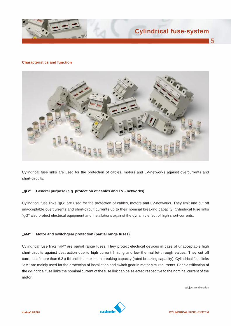
Characteristics and function
Cylindrical fuse links are used for the protection of cables, motors and LV-networks against overcurrents and
short-circuits.
„gG“ General purpose (e.g. protection of cables and LV - networks)
Cylindrical fuse links "gG" are used for the protection of cables, motors and LV-networks. They limit and cut off
unacceptable overcurrents and short-circuit currents up to their nominal breaking capacity. Cylindrical fuse links
"gG" also protect electrical equipment and installations against the dynamic effect of high short-currents.
„aM“ Motor and switchgear protection (partial range fuses)
Cylindrical fuse links "aM" are partial range fuses. They protect electrical devices in case of unacceptable high
short-circuits against destruction due to high current limiting and low thermal let-through values. They cut off
currents of more than 6.3 x IN until the maximum breaking capacity (rated breaking capacity). Cylindrical fuse links
"aM" are mainly used for the protection of installation and switch gear in motor circuit currents. For classification of
the cylindrical fuse links the nominal current of the fuse link can be selected respective to the nominal current of the
motor.
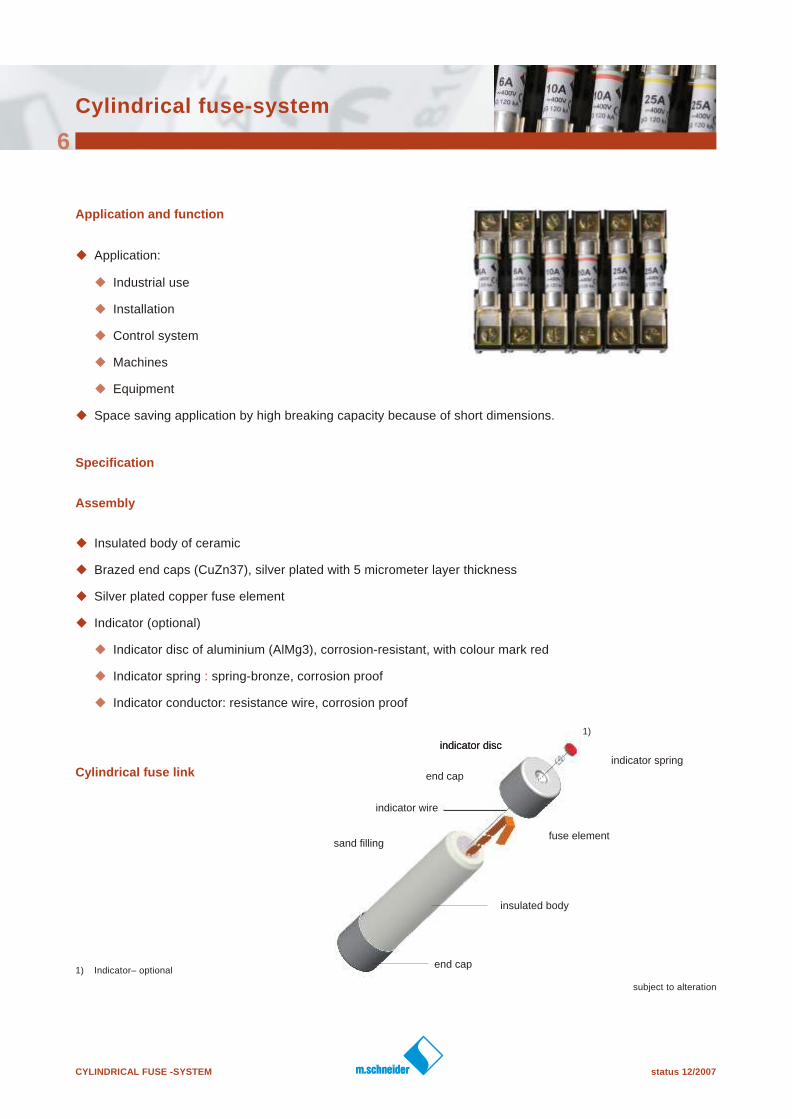
indicator disc
indicator spring
end cap
indicator disc
indicator wire
end cap
fuse elementsand filling
insulated body
CYLINDRICAL FUSE -SYSTEM status 12/2007
subject to alteration
Cylindrical fuse-system
6
1) Indicator– optional
1)
Application and function
u Application:
u Industrial use
u Installation
u Control system
u Machines
u Equipment
u Space saving application by high breaking capacity because of short dimensions.
Specification
Assembly
u Insulated body of ceramic
u Brazed end caps (CuZn37), silver plated with 5 micrometer layer thickness
u Silver plated copper fuse element
u Indicator (optional)
u Indicator disc of aluminium (AlMg3), corrosion-resistant, with colour mark red
u Indicator spring : spring-bronze, corrosion proof
u Indicator conductor: resistance wire, corrosion proof
Cylindrical fuse link
status 12/2007 CYLINDRICAL FUSE -SYSTEM
subject to alteration
Cylindrical fuse-system
7
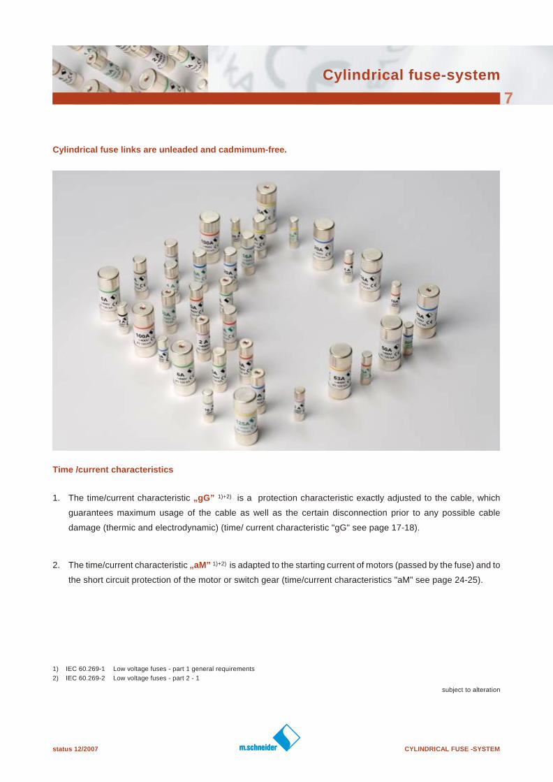
Cylindrical fuse links are unleaded and cadmimum-free.
Time /current characteristics
1. The time/current characteristic „gG” 1)+2) is a protection characteristic exactly adjusted to the cable, which
guarantees maximum usage of the cable as well as the certain disconnection prior to any possible cable
damage (thermic and electrodynamic) (time/ current characteristic "gG" see page 17-18).
2. The time/current characteristic „aM” 1)+2) is adapted to the starting current of motors (passed by the fuse) and to
the short circuit protection of the motor or switch gear (time/current characteristics "aM" see page 24-25).
1) IEC 60.269-1 Low voltage fuses - part 1 general requirements
2) IEC 60.269-2 Low voltage fuses - part 2 - 1
CYLINDRICAL FUSE -SYSTEM status 12/2007
subject to alteration
Cylindrical fuse-system
8
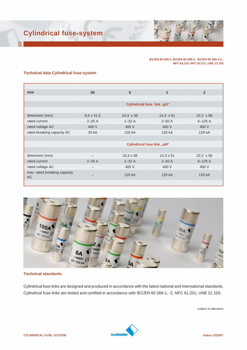
Technical data Cylindrical fuse-system
size 00 0 1 2
Cylindrical fuse link „gG“
dimension (mm) 8,5 x 31,5 10,3 x 38 14,3 x 51 22,2 x 58
rated current 2–25 A 1–32 A 2–50 A 6–125 A
rated voltage AC 400 V 400 V 400 V 400 V
rated breaking capacity AC 20 kA 120 kA 120 kA 120 kA
Cylindrical fuse link „aM“
dimension (mm) – 10,3 x 38 14,3 x 51 22,2 x 58
rated current 2–25 A 1–32 A 2–50 A 6–125 A
rated voltage AC – 400 V 400 V 400 V
max. rated breaking capacity
AC– 120 kA 120 kA 120 kA
Technical standards
Cylindrical fuse links are designed and produced in accordance with the latest national and international standards.
Cylindrical fuse links are tested and certified in accordance with IEC/EN 60 269-1, -2, NFC 61.201, UNE 21.103.
IEC/EN 60 269-1, IEC/EN 60 269-2, IEC/EN 60 269-2-1,
NFC 63.210, NFC 63.211, UNE 21.103
status 12/2007 CYLINDRICAL FUSE -SYSTEM
Cylindrical fuse-system
9
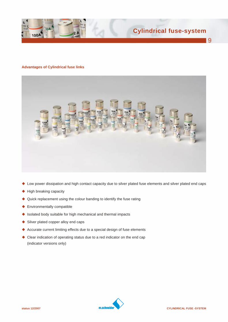
Advantages of Cylindrical fuse links
u Low power dissipation and high contact capacity due to silver plated fuse elements and silver plated end caps
u High breaking capacity
u Quick replacement using the colour banding to identify the fuse rating
u Environmentally compatible
u Isolated body suitable for high mechanical and thermal impacts
u Silver plated copper alloy end caps
u Accurate current limiting effects due to a special design of fuse elements
u Clear indication of operating status due to a red indicator on the end cap
(indicator versions only)
CYLINDRICAL FUSE -SYSTEM status 12/2007
subject to alteration
Cylindrical fuse-system
10
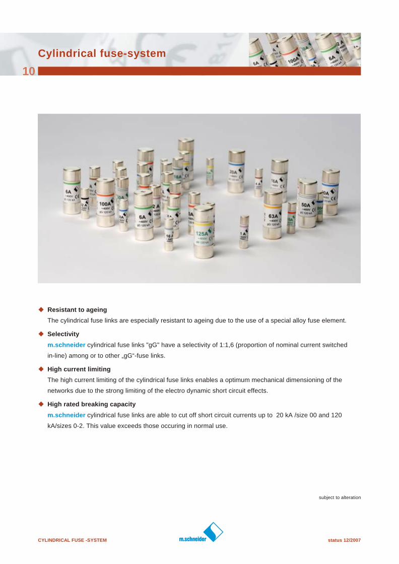
u Resistant to ageing
The cylindrical fuse links are especially resistant to ageing due to the use of a special alloy fuse element.
u Selectivity
m.schneider cylindrical fuse links "gG" have a selectivity of 1:1,6 (proportion of nominal current switched
in-line) among or to other „gG“-fuse links.
u High current limiting
The high current limiting of the cylindrical fuse links enables a optimum mechanical dimensioning of the
networks due to the strong limiting of the electro dynamic short circuit effects.
u High rated breaking capacity
m.schneider cylindrical fuse links are able to cut off short circuit currents up to 20 kA /size 00 and 120
kA/sizes 0-2. This value exceeds those occuring in normal use.
status 12/2007 CYLINDRICAL FUSE -SYSTEM
subject to alteration
Cylindrical fuse-system
11
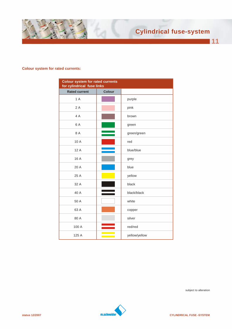
Colour system for rated currents:
Colour system for rated currents
for cylindrical fuse links
Rated current Colour
1 A purple
2 A pink
4 A brown
6 A green
8 A green/green
10 A red
12 A blue/blue
16 A grey
20 A blue
25 A yellow
32 A black
40 A black/black
50 A white
63 A copper
80 A silver
100 A red/red
125 A yellow/yellow
CYLINDRICAL FUSE -SYSTEM status 12/2007
subject to alteration
Cylindrical fuse-system
12
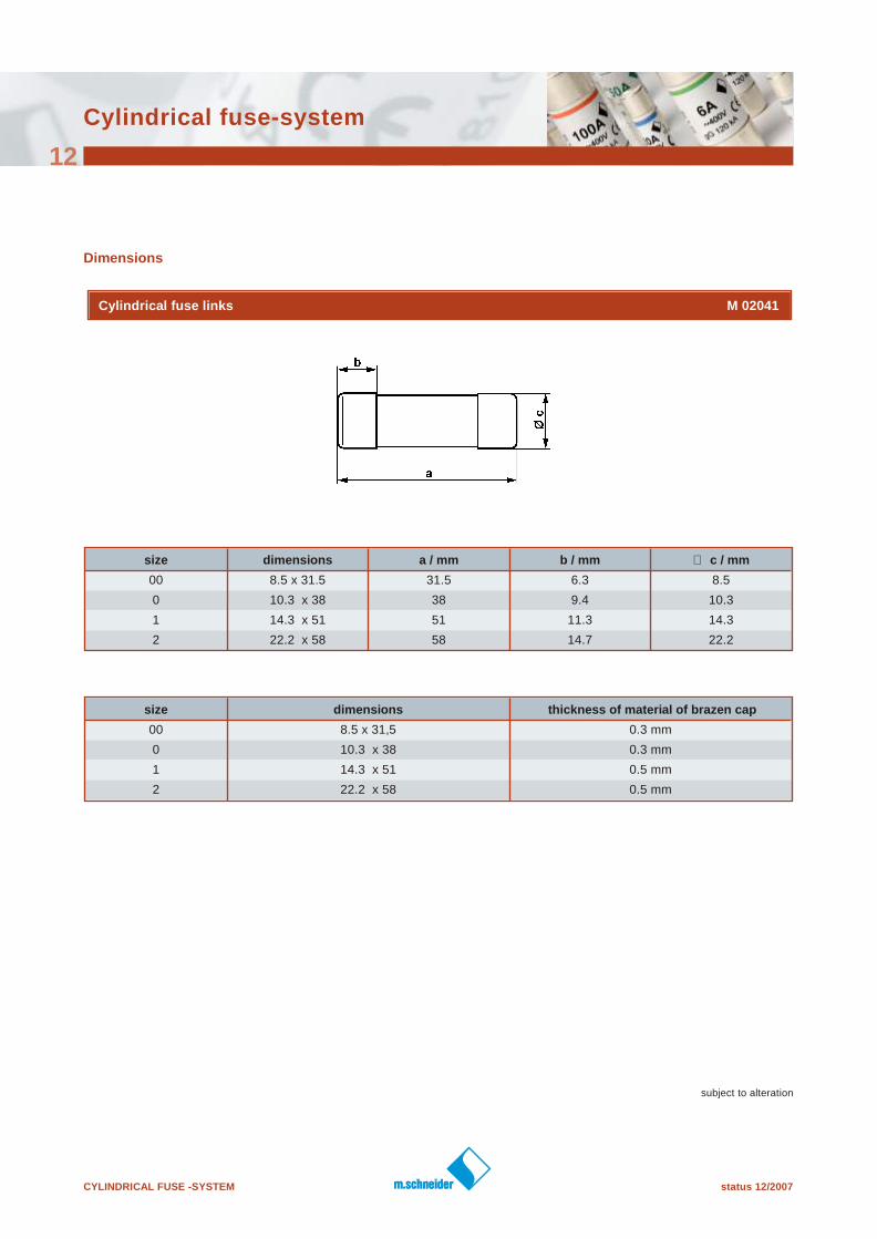
size dimensions a / mm b / mm ∅ c / mm
00 8.5 x 31.5 31.5 6.3 8.5
0 10.3 x 38 38 9.4 10.3
1 14.3 x 51 51 11.3 14.3
2 22.2 x 58 58 14.7 22.2
size dimensions thickness of material of brazen cap
00 8.5 x 31,5 0.3 mm
0 10.3 x 38 0.3 mm
1 14.3 x 51 0.5 mm
2 22.2 x 58 0.5 mm
Dimensions
Cylindrical fuse links M 02041
status 12/2007 CYLINDRICAL FUSE -SYSTEM
subject to alteration
Cylindrical fuse-system
13
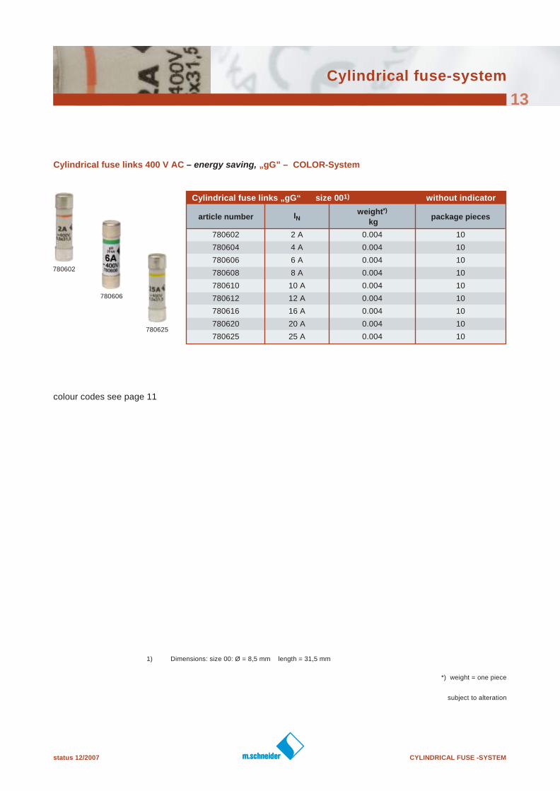
Cylindrical fuse links 400 V AC – energy saving, „gG” – COLOR- System
Cylindrical fuse links „gG“ size 001) without indicator
article number INweight*)
kgpackage pieces
780602 2 A 0.004 10
780604 4 A 0.004 10
780606 6 A 0.004 10
780608 8 A 0.004 10
780610 10 A 0.004 10
780612 12 A 0.004 10
780616 16 A 0.004 10
780620 20 A 0.004 10
780625 25 A 0.004 10
colour codes see page 11
1) Dimensions: size 00: Ø = 8,5 mm length = 31,5 mm
780602
780625
780606
*) weight = one piece
CYLINDRICAL FUSE -SYSTEM status 12/2007
subject to alteration
Cylindrical fuse-system
14
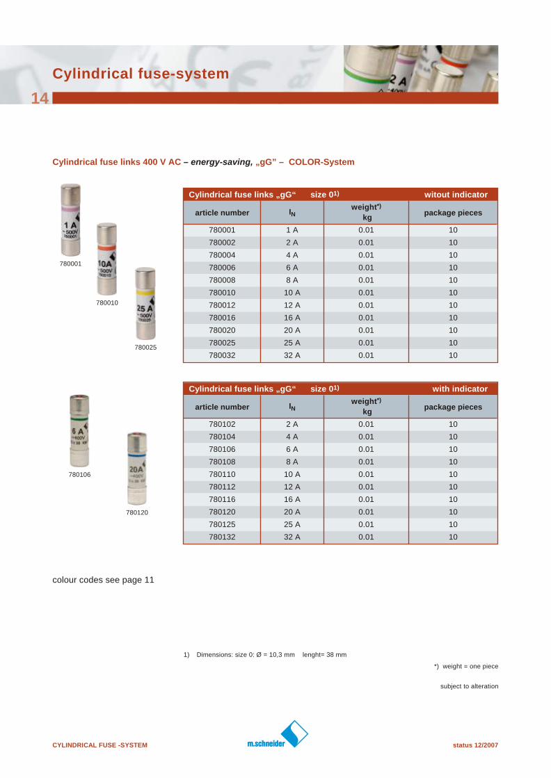
Cylindrical fuse links 400 V AC – energy-saving, „gG” – COLOR- System
Cylindrical fuse links „gG“ size 01) witout indicator
article number INweight*)
kgpackage pieces
780001 1 A 0.01 10
780002 2 A 0.01 10
780004 4 A 0.01 10
780006 6 A 0.01 10
780008 8 A 0.01 10
780010 10 A 0.01 10
780012 12 A 0.01 10
780016 16 A 0.01 10
780020 20 A 0.01 10
780025 25 A 0.01 10
780032 32 A 0.01 10
Cylindrical fuse links „gG“ size 01) with indicator
article number INweight*)
kgpackage pieces
780102 2 A 0.01 10
780104 4 A 0.01 10
780106 6 A 0.01 10
780108 8 A 0.01 10
780110 10 A 0.01 10
780112 12 A 0.01 10
780116 16 A 0.01 10
780120 20 A 0.01 10
780125 25 A 0.01 10
780132 32 A 0.01 10
colour codes see page 11
780120
780010
1) Dimensions: size 0: Ø = 10,3 mm lenght= 38 mm
780001
780025
780106
*) weight = one piece
status 12/2007 CYLINDRICAL FUSE -SYSTEM
subject to alteration
Cylindrical fuse-system
15
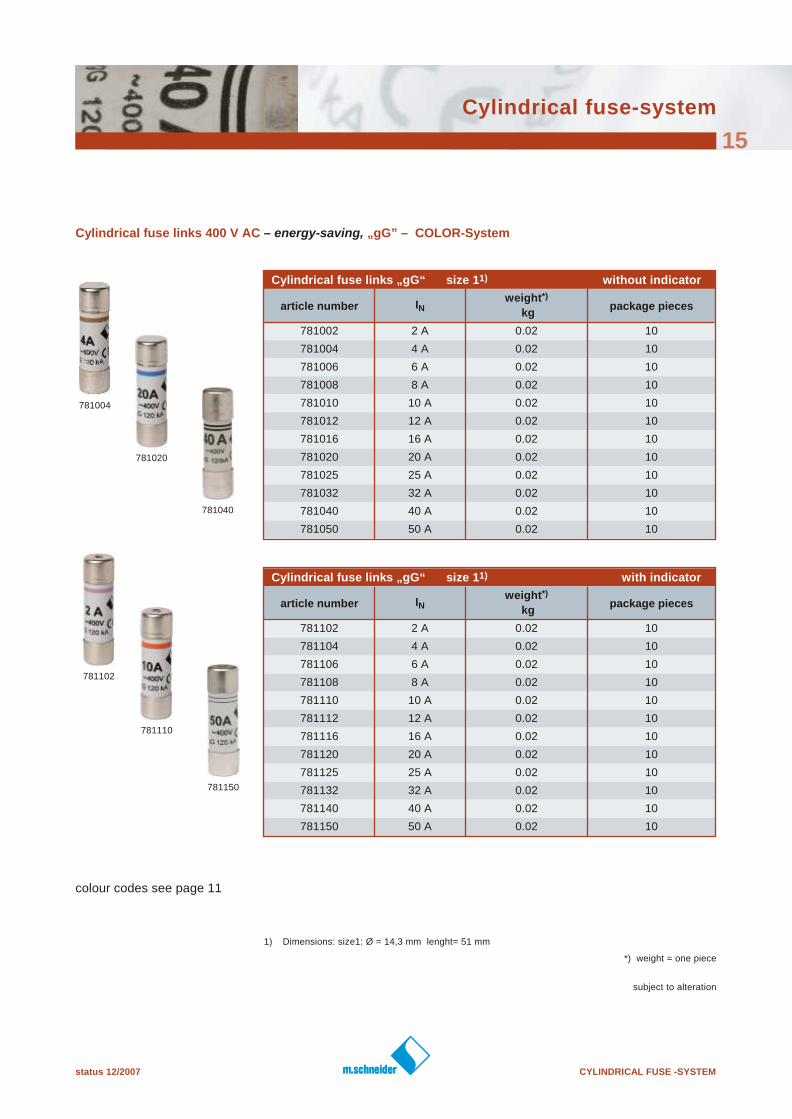
Cylindrical fuse links 400 V AC – energy-saving, „gG” – COLOR- System
Cylindrical fuse links „gG“ size 11) without indicator
article number INweight*)
kgpackage pieces
781002 2 A 0.02 10
781004 4 A 0.02 10
781006 6 A 0.02 10
781008 8 A 0.02 10
781010 10 A 0.02 10
781012 12 A 0.02 10
781016 16 A 0.02 10
781020 20 A 0.02 10
781025 25 A 0.02 10
781032 32 A 0.02 10
781040 40 A 0.02 10
781050 50 A 0.02 10
Cylindrical fuse links „gG“ size 11) with indicator
article number INweight*)
kgpackage pieces
781102 2 A 0.02 10
781104 4 A 0.02 10
781106 6 A 0.02 10
781108 8 A 0.02 10
781110 10 A 0.02 10
781112 12 A 0.02 10
781116 16 A 0.02 10
781120 20 A 0.02 10
781125 25 A 0.02 10
781132 32 A 0.02 10
781140 40 A 0.02 10
781150 50 A 0.02 10
colour codes see page 11
781102
1) Dimensions: size1: Ø = 14,3 mm lenght= 51 mm
781004
781020
781040
781110
781150
*) weight = one piece
CYLINDRICAL FUSE -SYSTEM status 12/2007
subject to alteration
Cylindrical fuse-system
16
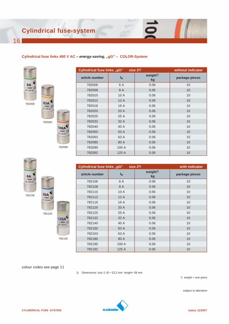
Cylindrical fuse links 400 V AC – energy-saving, „gG” – COLOR- System
Cylindrical fuse links „gG“ size 21) without indicator
article number INweight*)
kgpackage pieces
782006 6 A 0.06 10
782008 8 A 0.06 10
782010 10 A 0.06 10
782012 12 A 0.06 10
782016 16 A 0.06 10
782020 20 A 0.06 10
782025 25 A 0.06 10
782032 32 A 0.06 10
782040 40 A 0.06 10
782050 50 A 0.06 10
782063 63 A 0.06 10
782080 80 A 0.06 10
782090 100 A 0.06 10
782092 125 A 0.06 10
Cylindrical fuse links „gG“ size 21) with indicator
article number INweight*)
kgpackage pieces
782106 6 A 0.06 10
782108 8 A 0.06 10
782110 10 A 0.06 10
782112 12 A 0.06 10
782116 16 A 0.06 10
782120 20 A 0.06 10
782125 25 A 0.06 10
782132 32 A 0.06 10
782140 40 A 0.06 10
782150 50 A 0.06 10
782163 63 A 0.06 10
782180 80 A 0.06 10
782190 100 A 0.06 10
782192 125 A 0.06 10
colour codes see page 11
1) Dimensions: size 2: Ø = 22,2 mm lenght= 58 mm
782006
782090
782063
782106
782192
782120
*) weight = one piece
status 12/2007 CYLINDRICAL FUSE -SYSTEM
Cylindrical fuse-system
17
subject to alteration
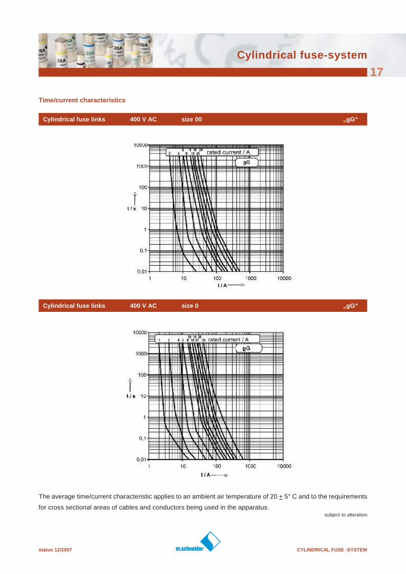
Time/current characteristics
Cylindrical fuse links 400 V AC size 00 „gG“
The average time/current characteristic applies to an ambient air temperature of 20 + 5° C and to the requirements
for cross sectional areas of cables and conductors being used in the apparatus.
Cylindrical fuse links 400 V AC size 0 „gG“
CYLINDRICAL FUSE -SYSTEM status 12/2007
Cylindrical fuse-system
18
subject to alteration
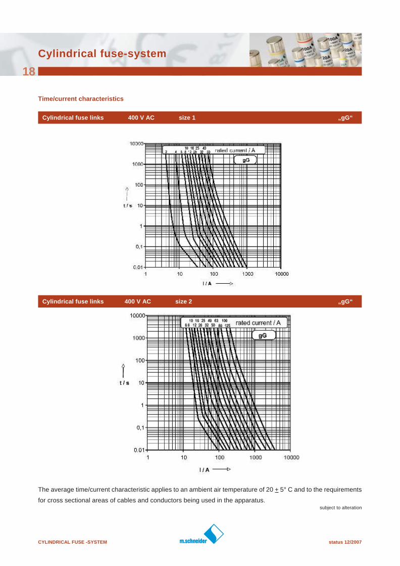
Time/current characteristics
Cylindrical fuse links 400 V AC size 1 „gG“
The average time/current characteristic applies to an ambient air temperature of 20 + 5° C and to the requirements
for cross sectional areas of cables and conductors being used in the apparatus.
Cylindrical fuse links 400 V AC size 2 „gG“
status 12/2007 CYLINDRICAL FUSE -SYSTEM
subject to alteration
Cylindrical fuse-system
19
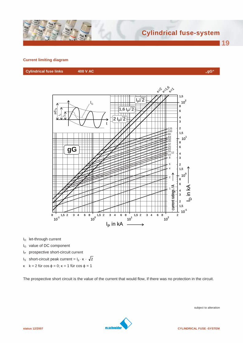
Current limiting diagram
Cylindrical fuse links 400 V AC „gG“
I in kAPI in kAP
I in
kA
DI in
kA
D
-110
-110
-110
-110
010
010
010
010
110
110
110
110
210
210
210
210
1,51,5 22 33 66 8844
1,51,5
22
33
66
88
44
1,51,5
22
33
66
88
44
1,51,5
22
33
66
88
44
1,51,5
1,51,5 22 33 66 88441,51,5 22 33 66 8844 2288
t
IG
2 2
IP
2 2
IP
I S I D
I 2PI 2P
I 2PI 2P1,61,6
I 2PI 2P22
125100
6380
50
810
16 12
20253240
curr
ent r
atin
gs /
Acu
rren
t rat
ings
/ A
κ=1,6κ=2
κ=1
gG
2
1
4
6
ID let-through current
IG value of DC component
IP prospective short-circuit current
IS short-circuit peak current = Ip · κ ·
κ k = 2 für cos ϕ = 0; κ = 1 für cos ϕ = 1
The prospective short circuit is the value of the current that would flow, if there was no protection in the circuit.
2
CYLINDRICAL FUSE -SYSTEM status 12/2007
subject to alteration
Cylindrical fuse-system
20
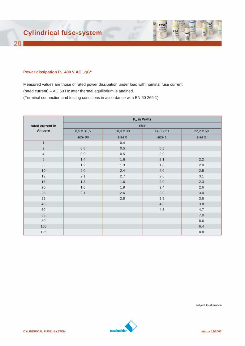
Power dissipation Pn 400 V AC „gG“
Measured values are those of rated power dissipation under load with nominal fuse current
(rated current) – AC 50 Hz after thermal equilibrium is attained.
(Terminal connection and testing conditions in accordance with EN 60 269-1).
rated current in
Ampere
Pn in Watts
size
8,5 x 31,5 10,3 x 38 14,3 x 51 22,2 x 58
size 00 size 0 size 1 size 2
1 0.4
2 0.6 0.5 0.8
4 0.9 0.5 2.0
6 1.4 1.6 2.1 2.2
8 1.2 1.3 1.8 2.0
10 2.0 2.4 2.0 2.5
12 2.1 2.7 2.6 3.1
16 1.3 1.6 2.0 2.3
20 1.6 1.9 2.4 2.6
25 2.1 2.6 3.0 3.4
32 2.8 3.5 3.6
40 4.3 3.8
50 4.5 4.7
63 7.0
80 8.6
100 6.4
125 8.8
status 12/2007 CYLINDRICAL FUSE -SYSTEM
subject to alteration
Cylindrical fuse-system
21
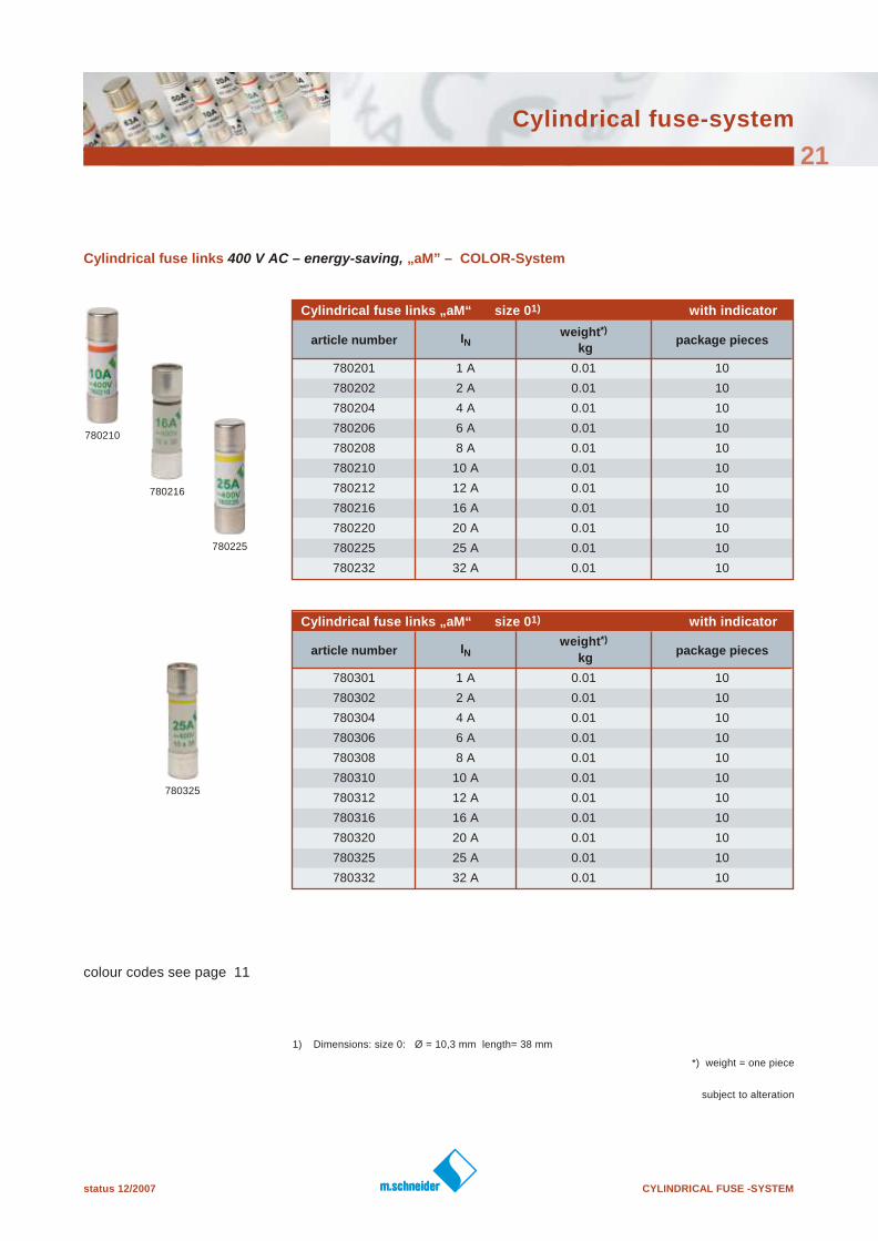
Cylindrical fuse links 400 V AC – energy-saving, „aM” – COLOR- System
Cylindrical fuse links „aM“ size 01) with indicator
article number INweight*)
kgpackage pieces
780201 1 A 0.01 10
780202 2 A 0.01 10
780204 4 A 0.01 10
780206 6 A 0.01 10
780208 8 A 0.01 10
780210 10 A 0.01 10
780212 12 A 0.01 10
780216 16 A 0.01 10
780220 20 A 0.01 10
780225 25 A 0.01 10
780232 32 A 0.01 10
Cylindrical fuse links „aM“ size 01) with indicator
article number INweight*)
kgpackage pieces
780301 1 A 0.01 10
780302 2 A 0.01 10
780304 4 A 0.01 10
780306 6 A 0.01 10
780308 8 A 0.01 10
780310 10 A 0.01 10
780312 12 A 0.01 10
780316 16 A 0.01 10
780320 20 A 0.01 10
780325 25 A 0.01 10
780332 32 A 0.01 10
colour codes see page 11
1) Dimensions: size 0: Ø = 10,3 mm length= 38 mm
780210
780216
780225
780325
*) weight = one piece
CYLINDRICAL FUSE -SYSTEM status 12/2007
subject to alteration
Cylindrical fuse-system
22
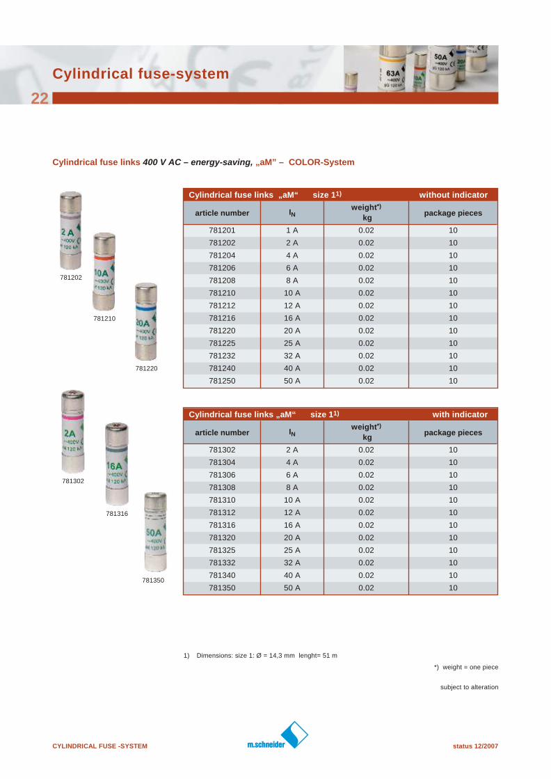
Cylindrical fuse links 400 V AC – energy-saving, „aM” – COLOR- System
Cylindrical fuse links „aM“ size 11) without indicator
article number INweight*)
kgpackage pieces
781201 1 A 0.02 10
781202 2 A 0.02 10
781204 4 A 0.02 10
781206 6 A 0.02 10
781208 8 A 0.02 10
781210 10 A 0.02 10
781212 12 A 0.02 10
781216 16 A 0.02 10
781220 20 A 0.02 10
781225 25 A 0.02 10
781232 32 A 0.02 10
781240 40 A 0.02 10
781250 50 A 0.02 10
Cylindrical fuse links „aM“ size 11) with indicator
article number INweight*)
kgpackage pieces
781302 2 A 0.02 10
781304 4 A 0.02 10
781306 6 A 0.02 10
781308 8 A 0.02 10
781310 10 A 0.02 10
781312 12 A 0.02 10
781316 16 A 0.02 10
781320 20 A 0.02 10
781325 25 A 0.02 10
781332 32 A 0.02 10
781340 40 A 0.02 10
781350 50 A 0.02 10
1) Dimensions: size 1: Ø = 14,3 mm lenght= 51 m
781202
781210
781220
781350
781302
781316
*) weight = one piece
status 12/2007 CYLINDRICAL FUSE -SYSTEM
subject to alteration
Cylindrical fuse-system
23
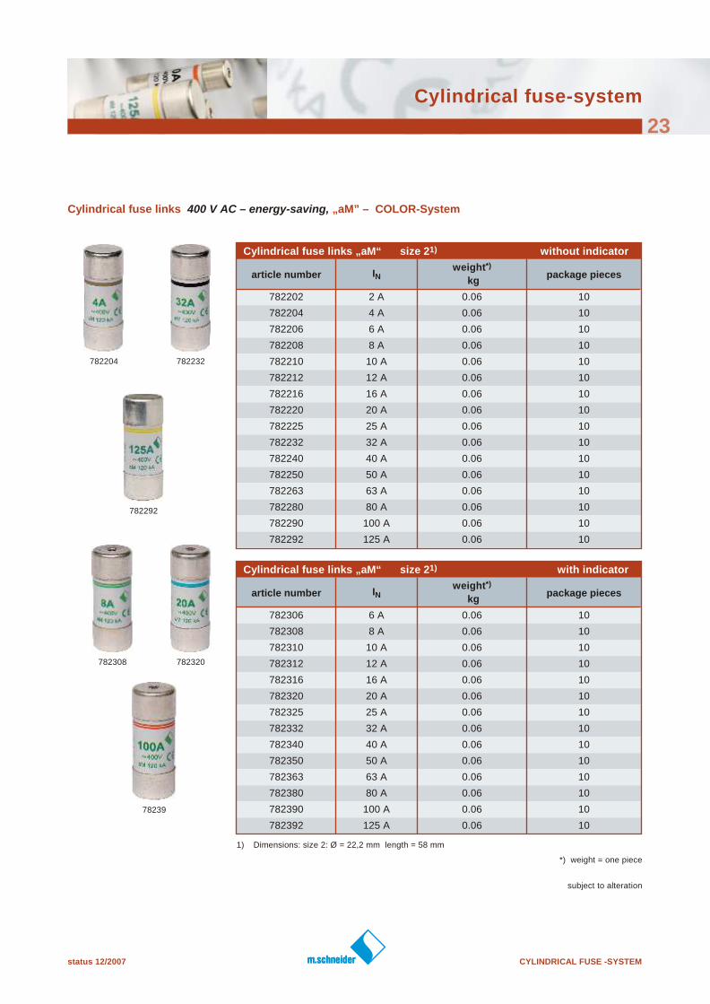
Cylindrical fuse links 400 V AC – energy-saving, „aM” – COLOR- System
Cylindrical fuse links „aM“ size 21) without indicator
article number INweight*)
kgpackage pieces
782202 2 A 0.06 10
782204 4 A 0.06 10
782206 6 A 0.06 10
782208 8 A 0.06 10
782210 10 A 0.06 10
782212 12 A 0.06 10
782216 16 A 0.06 10
782220 20 A 0.06 10
782225 25 A 0.06 10
782232 32 A 0.06 10
782240 40 A 0.06 10
782250 50 A 0.06 10
782263 63 A 0.06 10
782280 80 A 0.06 10
782290 100 A 0.06 10
782292 125 A 0.06 10
Cylindrical fuse links „aM“ size 21) with indicator
article number INweight*)
kgpackage pieces
782306 6 A 0.06 10
782308 8 A 0.06 10
782310 10 A 0.06 10
782312 12 A 0.06 10
782316 16 A 0.06 10
782320 20 A 0.06 10
782325 25 A 0.06 10
782332 32 A 0.06 10
782340 40 A 0.06 10
782350 50 A 0.06 10
782363 63 A 0.06 10
782380 80 A 0.06 10
782390 100 A 0.06 10
782392 125 A 0.06 10
1) Dimensions: size 2: Ø = 22,2 mm length = 58 mm
782292
782204 782232
782308 782320
78239
*) weight = one piece
CYLINDRICAL FUSE -SYSTEM status 12/2007
Cylindrical fuse-system
24
subject to alteration
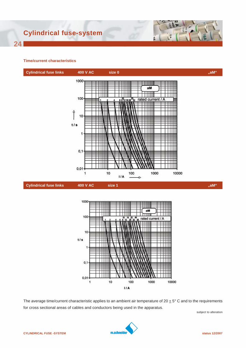
Time/current characteristics
Cylindrical fuse links 400 V AC size 0 „aM“
The average time/current characteristic applies to an ambient air temperature of 20 + 5° C and to the requirements
for cross sectional areas of cables and conductors being used in the apparatus.
Cylindrical fuse links 400 V AC size 1 „aM“
status 12/2007 CYLINDRICAL FUSE -SYSTEM
Cylindrical fuse-system
25
subject to alteration
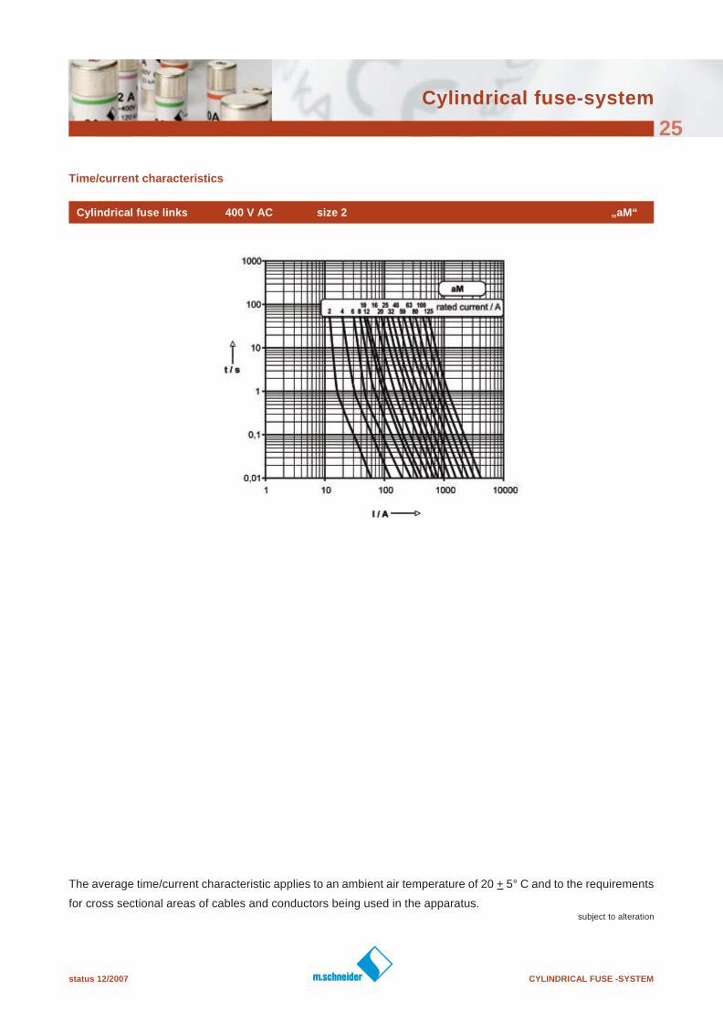
Time/current characteristics
Cylindrical fuse links 400 V AC size 2 „aM“
The average time/current characteristic applies to an ambient air temperature of 20 + 5° C and to the requirements
for cross sectional areas of cables and conductors being used in the apparatus.
CYLINDRICAL FUSE -SYSTEM status 12/2007
subject to alteration
Cylindrical fuse-system
26
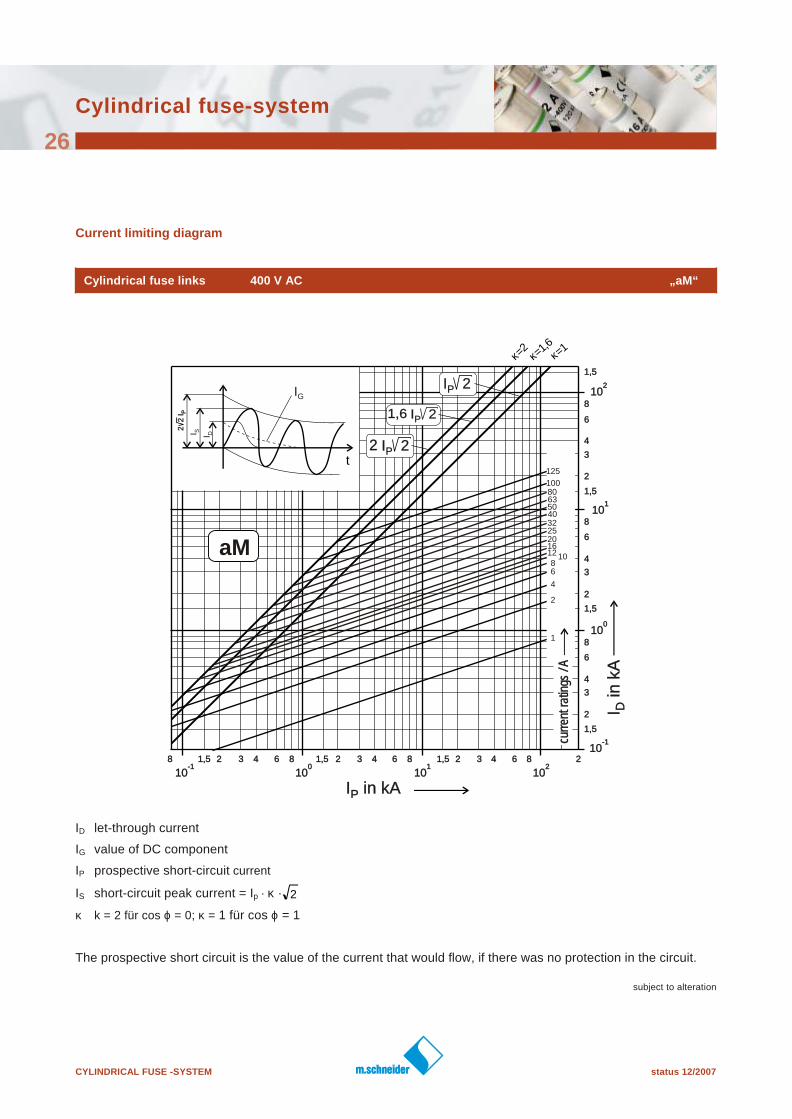
Current limiting diagram
Cylindrical fuse links 400 V AC „aM“
I in kAPI in kAP
I in
kA
DI in
kA
D
-110
-110
-110
-110
010
010
010
010
110
110
110
110
210
210
210
210
1,51,5 22 33 66 8844
1,51,5
22
33
66
88
44
1,51,5
22
33
66
88
44
1,51,5
22
33
66
88
44
1,51,5
1,51,5 22 33 66 88441,51,5 22 33 66 8844 2288
t
IG
2 2
IP
2 2
IP
I S I D
I 2PI 2P
I 2PI 2P1,61,6
I 2PI 2P22
125
100
6380
50
810
1612
20253240
curr
ent r
atin
gs /
Acu
rren
t rat
ings
/ A
κ=1,6κ=2
κ=1
aM
2
1
4
6
ID let-through current
IG value of DC component
IP prospective short-circuit current
IS short-circuit peak current = Ip · κ ·
κ k = 2 für cos ϕ = 0; κ = 1 für cos ϕ = 1
The prospective short circuit is the value of the current that would flow, if there was no protection in the circuit.
2
status 12/2007 CYLINDRICAL FUSE -SYSTEM
subject to alteration
Cylindrical fuse-system
27
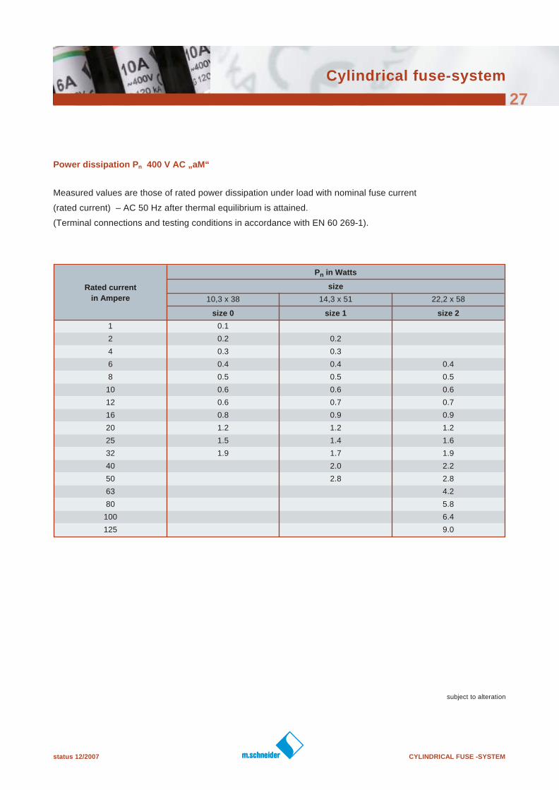
Power dissipation Pn 400 V AC „aM“
Measured values are those of rated power dissipation under load with nominal fuse current
(rated current) – AC 50 Hz after thermal equilibrium is attained.
(Terminal connections and testing conditions in accordance with EN 60 269-1).
Rated current
in Ampere
Pn in Watts
size
10,3 x 38 14,3 x 51 22,2 x 58
size 0 size 1 size 2
1 0.1
2 0.2 0.2
4 0.3 0.3
6 0.4 0.4 0.4
8 0.5 0.5 0.5
10 0.6 0.6 0.6
12 0.6 0.7 0.7
16 0.8 0.9 0.9
20 1.2 1.2 1.2
25 1.5 1.4 1.6
32 1.9 1.7 1.9
40 2.0 2.2
50 2.8 2.8
63 4.2
80 5.8
100 6.4
125 9.0
CYLINDRICAL FUSE -SYSTEM status 12/2007
Cylindrical fuse-system
28
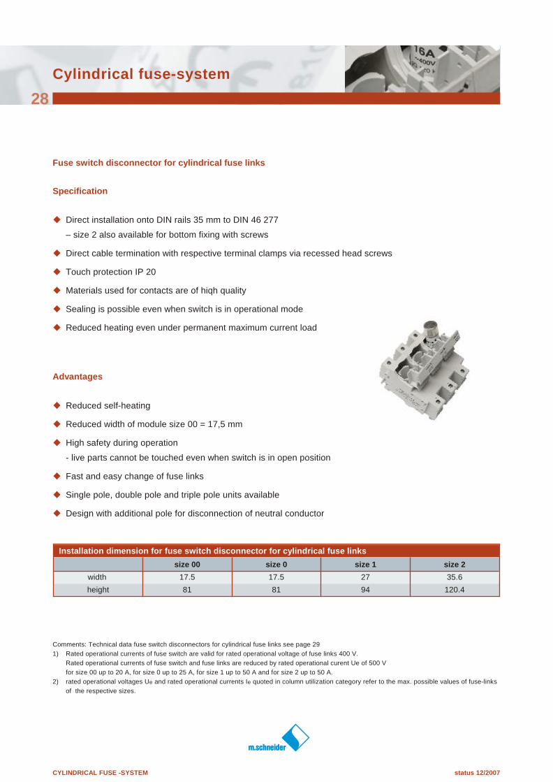
Fuse switch disconnector for cylindrical fuse links
Specification
u Direct installation onto DIN rails 35 mm to DIN 46 277
– size 2 also available for bottom fixing with screws
u Direct cable termination with respective terminal clamps via recessed head screws
u Touch protection IP 20
u Materials used for contacts are of hiqh quality
u Sealing is possible even when switch is in operational mode
u Reduced heating even under permanent maximum current load
Advantages
u Reduced self-heating
u Reduced width of module size 00 = 17,5 mm
u High safety during operation
- live parts cannot be touched even when switch is in open position
u Fast and easy change of fuse links
u Single pole, double pole and triple pole units available
u Design with additional pole for disconnection of neutral conductor
Installation dimension for fuse switch disconnector for cylindrical fuse links
size 00 size 0 size 1 size 2
width 17.5 17.5 27 35.6
height 81 81 94 120.4
Comments: Technical data fuse switch disconnectors for cylindrical fuse links see page 29
1) Rated operational currents of fuse switch are valid for rated operational voltage of fuse links 400 V.
Rated operational currents of fuse switch and fuse links are reduced by rated operational curent Ue of 500 V
for size 00 up to 20 A, for size 0 up to 25 A, for size 1 up to 50 A and for size 2 up to 50 A.
2) rated operational voltages Ue and rated operational currents Ie quoted in column utilization category refer to the max. possible values of fuse-links
of the respective sizes.
status 12/2007 CYLINDRICAL FUSE -SYSTEM
Cylindrical fuse-system
29
subject to alteration
in accordance with IEC/EN 60 947-1,60 947-3
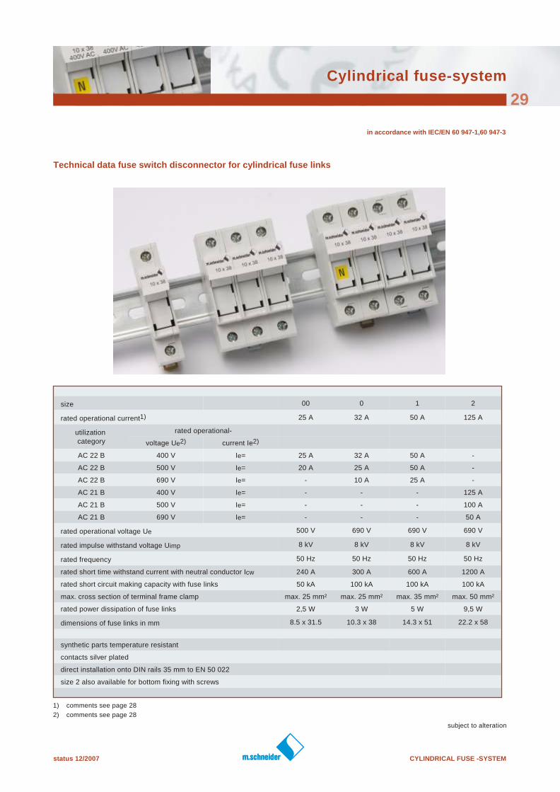
Technical data fuse switch disconnector for cylindrical fuse links
size 00 0 1 2
rated operational current1) 25 A 32 A 50 A 125 A
utilization category
rated operational-
voltage Ue2) current Ie2)
AC 22 B 400 V Ie= 25 A 32 A 50 A -
AC 22 B 500 V Ie= 20 A 25 A 50 A -
AC 22 B 690 V Ie= - 10 A 25 A -
AC 21 B 400 V Ie= - - - 125 A
AC 21 B 500 V Ie= - - - 100 A
AC 21 B 690 V Ie= - - - 50 A
rated operational voltage Ue 500 V 690 V 690 V 690 V
rated impulse withstand voltage Uimp 8 kV 8 kV 8 kV 8 kV
rated frequency 50 Hz 50 Hz 50 Hz 50 Hz
rated short time withstand current with neutral conductor Icw 240 A 300 A 600 A 1200 A
rated short circuit making capacity with fuse links 50 kA 100 kA 100 kA 100 kA
max. cross section of terminal frame clamp max. 25 mm² max. 25 mm² max. 35 mm² max. 50 mm²
rated power dissipation of fuse links 2,5 W 3 W 5 W 9,5 W
dimensions of fuse links in mm 8.5 x 31.5 10.3 x 38 14.3 x 51 22.2 x 58
synthetic parts temperature resistant
contacts silver plated
direct installation onto DIN rails 35 mm to EN 50 022
size 2 also available for bottom fixing with screws
1) comments see page 28
2) comments see page 28
CYLINDRICAL FUSE -SYSTEM status 12/2007
Cylindrical fuse-system
30
785130
785110 785111
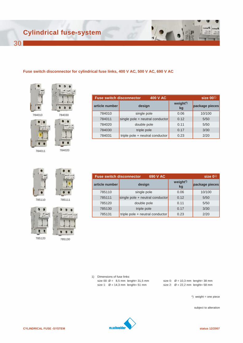
Fuse switch disconnector for cylindrical fuse links, 400 V AC, 500 V AC, 690 V AC
Fuse switch disconnector 400 V AC size 001)
article number designweight*)
kgpackage pieces
784010 single pole 0.06 10/100
784011 single pole + neutral conductor 0.12 5/50
784020 double pole 0.11 5/50
784030 triple pole 0.17 3/30
784031 triple pole + neutral conductor 0.23 2/20
Fuse switch disconnector 690 V AC size 01)
article number designweight*)
kgpackage pieces
785110 single pole 0.06 10/100
785111 single pole + neutral conductor 0.12 5/50
785120 double pole 0.11 5/50
785130 triple pole 0.17 3/30
785131 triple pole + neutral conductor 0.23 2/20
subject to alteration
784010
1) Dimensions of fuse links:
size 00: Ø = 8,5 mm lenght= 31,5 mm size 0: Ø = 10,3 mm lenght= 38 mm
size 1: Ø = 14,3 mm lenght= 51 mm size 2: Ø = 22,2 mm lenght= 58 mm
784011 784020
784030
785120
*) weight = one piece
status 12/2007 CYLINDRICAL FUSE -SYSTEM
Cylindrical fuse-system
31
subject to alteration
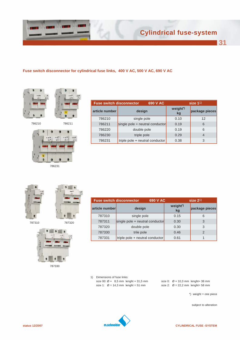
Fuse switch disconnector for cylindrical fuse links, 400 V AC, 500 V AC, 690 V AC
Fuse switch disconnector 690 V AC size 11)
article number designweight*)
kgpackage pieces
786210 single pole 0.10 12
786211 single pole + neutral conductor 0.19 6
786220 double pole 0.19 6
786230 triple pole 0.29 4
786231 triple pole + neutral conductor 0.38 3
Fuse switch disconnector 690 V AC size 21)
article number designweight*)
kgpackage pieces
787310 single pole 0.15 6
787311 single pole + neutral conductor 0.30 3
787320 double pole 0.30 3
787330 trile pole 0.46 2
787331 triple pole + neutral conductor 0.61 1
1) Dimensions of fuse links:
size 00: Ø = 8,5 mm lenght = 31,5 mm size 0: Ø = 10,3 mm lenght= 38 mm
size 1: Ø = 14,3 mm lenght = 51 mm size 2: Ø = 22,2 mm lenght= 58 mm
787310
786210 786211
786231
787320
787330
*) weight = one piece
CYLINDRICAL FUSE -SYSTEM status 12/2007
Cylindrical fuse-system
32
subject to alteration
Dimensions
Fuse switch disconnector for cylindrical fuse links size 00/0 M 02042
Fuse switch disconnector for cylindrical fuse links size 1 M 02043
dimensional drawing on request:
drawing no. (M . . . . .) see top banner right side
We are looking forward to receiving your enquiry
and send the drawing directly per e-mail.
dimensional drawing on request:
drawing no. (M . . . . .) see top banner right side
We are looking forward to receiving your enquiry
and send the drawing directly per e-mail.
status 12/2007 CYLINDRICAL FUSE -SYSTEM
Cylindrical fuse-system
33
subject to alteration
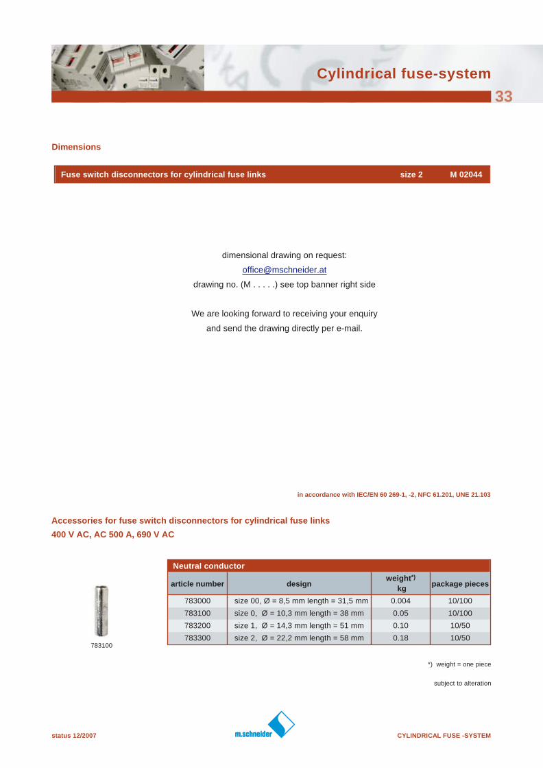
Dimensions
783100
in accordance with IEC/EN 60 269-1, -2, NFC 61.201, UNE 21.103
Accessories for fuse switch disconnectors for cylindrical fuse links
400 V AC, AC 500 A, 690 V AC
Neutral conductor
article number designweight*)
kgpackage pieces
783000 size 00, Ø = 8,5 mm length = 31,5 mm 0.004 10/100
783100 size 0, Ø = 10,3 mm length = 38 mm 0.05 10/100
783200 size 1, Ø = 14,3 mm length = 51 mm 0.10 10/50
783300 size 2, Ø = 22,2 mm length = 58 mm 0.18 10/50
Fuse switch disconnectors for cylindrical fuse links size 2 M 02044
*) weight = one piece
dimensional drawing on request:
drawing no. (M . . . . .) see top banner right side
We are looking forward to receiving your enquiry
and send the drawing directly per e-mail.
CYLINDRICAL FUSE -SYSTEM status 06/2007
subject to alteration
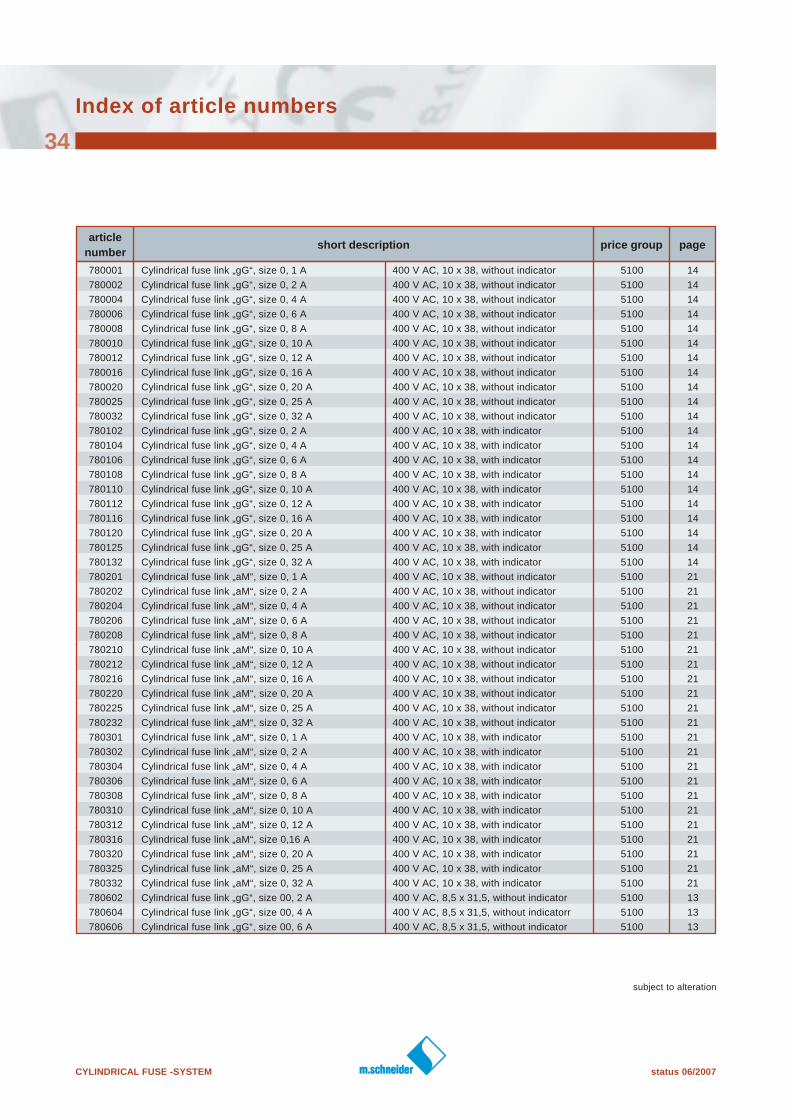
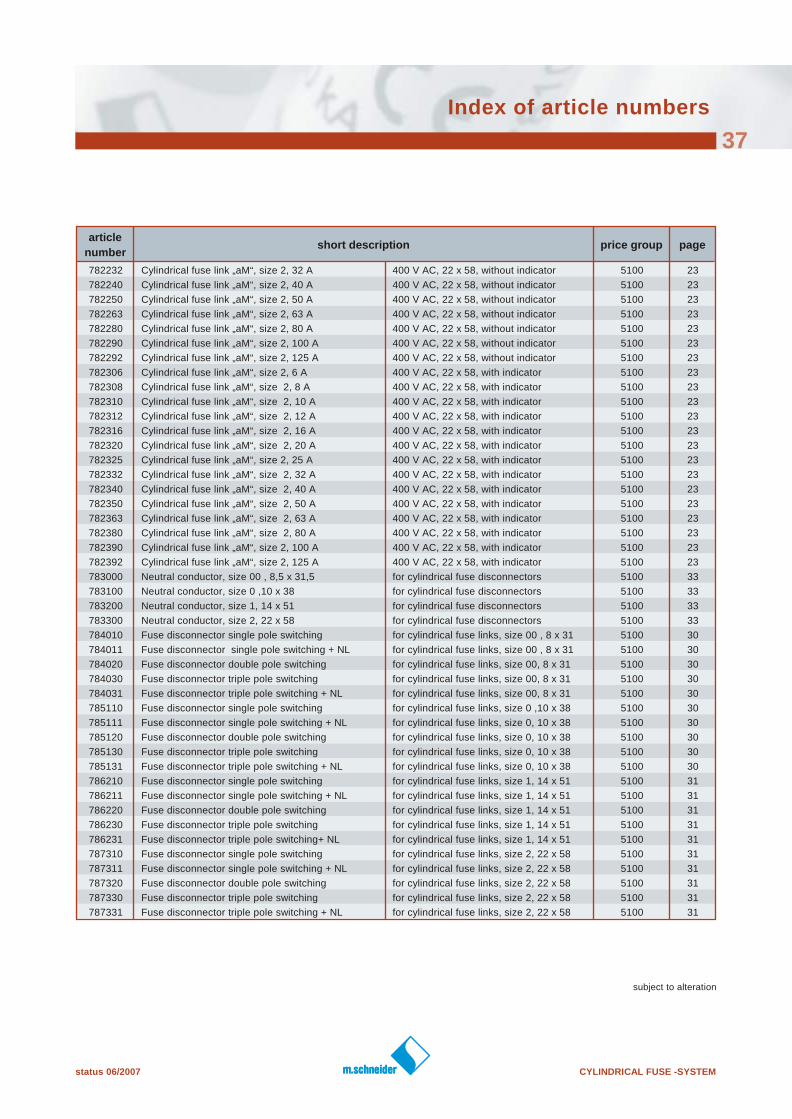
Index of article numbers
34
article
numbershort description price group page
780001 Cylindrical fuse link „gG“, size 0, 1 A 400 V AC, 10 x 38, without indicator 5100 14
780002 Cylindrical fuse link „gG“, size 0, 2 A 400 V AC, 10 x 38, without indicator 5100 14
780004 Cylindrical fuse link „gG“, size 0, 4 A 400 V AC, 10 x 38, without indicator 5100 14
780006 Cylindrical fuse link „gG“, size 0, 6 A 400 V AC, 10 x 38, without indicator 5100 14
780008 Cylindrical fuse link „gG“, size 0, 8 A 400 V AC, 10 x 38, without indicator 5100 14
780010 Cylindrical fuse link „gG“, size 0, 10 A 400 V AC, 10 x 38, without indicator 5100 14
780012 Cylindrical fuse link „gG“, size 0, 12 A 400 V AC, 10 x 38, without indicator 5100 14
780016 Cylindrical fuse link „gG“, size 0, 16 A 400 V AC, 10 x 38, without indicator 5100 14
780020 Cylindrical fuse link „gG“, size 0, 20 A 400 V AC, 10 x 38, without indicator 5100 14
780025 Cylindrical fuse link „gG“, size 0, 25 A 400 V AC, 10 x 38, without indicator 5100 14
780032 Cylindrical fuse link „gG“, size 0, 32 A 400 V AC, 10 x 38, without indicator 5100 14
780102 Cylindrical fuse link „gG“, size 0, 2 A 400 V AC, 10 x 38, with indicator 5100 14
780104 Cylindrical fuse link „gG“, size 0, 4 A 400 V AC, 10 x 38, with indicator 5100 14
780106 Cylindrical fuse link „gG“, size 0, 6 A 400 V AC, 10 x 38, with indicator 5100 14
780108 Cylindrical fuse link „gG“, size 0, 8 A 400 V AC, 10 x 38, with indicator 5100 14
780110 Cylindrical fuse link „gG“, size 0, 10 A 400 V AC, 10 x 38, with indicator 5100 14
780112 Cylindrical fuse link „gG“, size 0, 12 A 400 V AC, 10 x 38, with indicator 5100 14
780116 Cylindrical fuse link „gG“, size 0, 16 A 400 V AC, 10 x 38, with indicator 5100 14
780120 Cylindrical fuse link „gG“, size 0, 20 A 400 V AC, 10 x 38, with indicator 5100 14
780125 Cylindrical fuse link „gG“, size 0, 25 A 400 V AC, 10 x 38, with indicator 5100 14
780132 Cylindrical fuse link „gG“, size 0, 32 A 400 V AC, 10 x 38, with indicator 5100 14
780201 Cylindrical fuse link „aM“, size 0, 1 A 400 V AC, 10 x 38, without indicator 5100 21
780202 Cylindrical fuse link „aM“, size 0, 2 A 400 V AC, 10 x 38, without indicator 5100 21
780204 Cylindrical fuse link „aM“, size 0, 4 A 400 V AC, 10 x 38, without indicator 5100 21
780206 Cylindrical fuse link „aM“, size 0, 6 A 400 V AC, 10 x 38, without indicator 5100 21
780208 Cylindrical fuse link „aM“, size 0, 8 A 400 V AC, 10 x 38, without indicator 5100 21
780210 Cylindrical fuse link „aM“, size 0, 10 A 400 V AC, 10 x 38, without indicator 5100 21
780212 Cylindrical fuse link „aM“, size 0, 12 A 400 V AC, 10 x 38, without indicator 5100 21
780216 Cylindrical fuse link „aM“, size 0, 16 A 400 V AC, 10 x 38, without indicator 5100 21
780220 Cylindrical fuse link „aM“, size 0, 20 A 400 V AC, 10 x 38, without indicator 5100 21
780225 Cylindrical fuse link „aM“, size 0, 25 A 400 V AC, 10 x 38, without indicator 5100 21
780232 Cylindrical fuse link „aM“, size 0, 32 A 400 V AC, 10 x 38, without indicator 5100 21
780301 Cylindrical fuse link „aM“, size 0, 1 A 400 V AC, 10 x 38, with indicator 5100 21
780302 Cylindrical fuse link „aM“, size 0, 2 A 400 V AC, 10 x 38, with indicator 5100 21
780304 Cylindrical fuse link „aM“, size 0, 4 A 400 V AC, 10 x 38, with indicator 5100 21
780306 Cylindrical fuse link „aM“, size 0, 6 A 400 V AC, 10 x 38, with indicator 5100 21
780308 Cylindrical fuse link „aM“, size 0, 8 A 400 V AC, 10 x 38, with indicator 5100 21
780310 Cylindrical fuse link „aM“, size 0, 10 A 400 V AC, 10 x 38, with indicator 5100 21
780312 Cylindrical fuse link „aM“, size 0, 12 A 400 V AC, 10 x 38, with indicator 5100 21
780316 Cylindrical fuse link „aM“, size 0,16 A 400 V AC, 10 x 38, with indicator 5100 21
780320 Cylindrical fuse link „aM“, size 0, 20 A 400 V AC, 10 x 38, with indicator 5100 21
780325 Cylindrical fuse link „aM“, size 0, 25 A 400 V AC, 10 x 38, with indicator 5100 21
780332 Cylindrical fuse link „aM“, size 0, 32 A 400 V AC, 10 x 38, with indicator 5100 21
780602 Cylindrical fuse link „gG“, size 00, 2 A 400 V AC, 8,5 x 31,5, without indicator 5100 13
780604 Cylindrical fuse link „gG“, size 00, 4 A 400 V AC, 8,5 x 31,5, without indicatorr 5100 13
780606 Cylindrical fuse link „gG“, size 00, 6 A 400 V AC, 8,5 x 31,5, without indicator 5100 13
status 06/2007 CYLINDRICAL FUSE -SYSTEM
subject to alteration
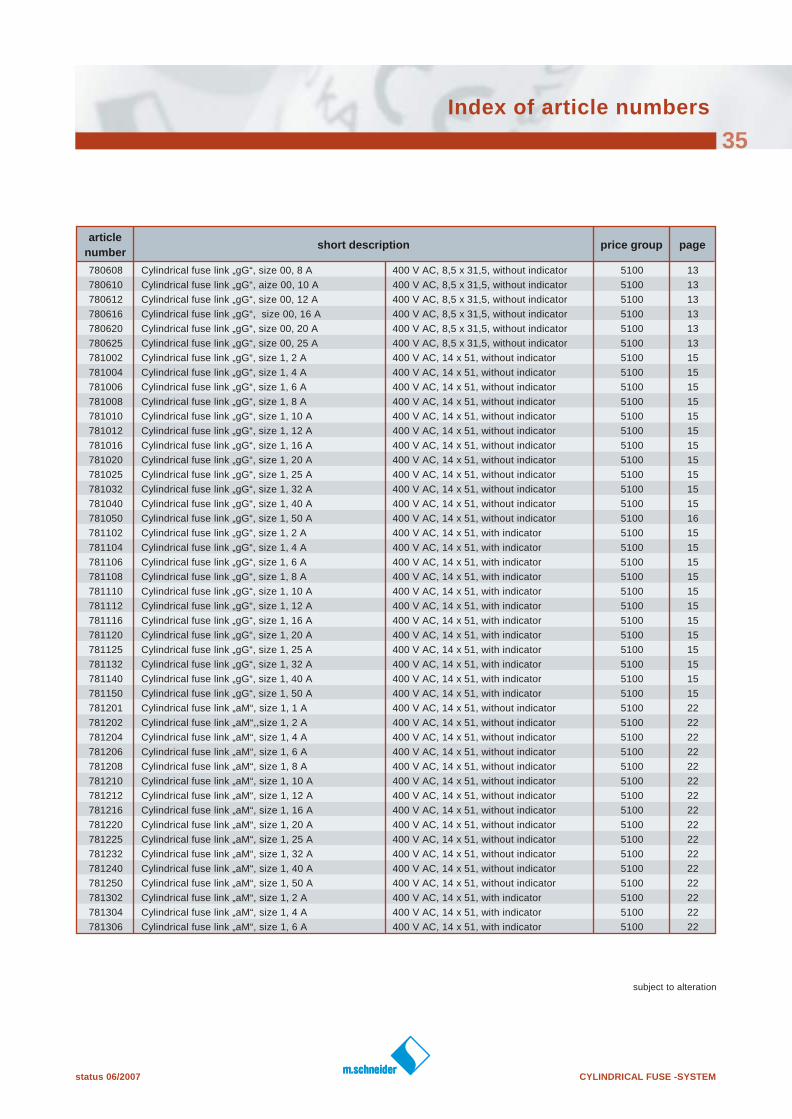
Index of article numbers
35
article
numbershort description price group page
780608 Cylindrical fuse link „gG“, size 00, 8 A 400 V AC, 8,5 x 31,5, without indicator 5100 13
780610 Cylindrical fuse link „gG“, aize 00, 10 A 400 V AC, 8,5 x 31,5, without indicator 5100 13
780612 Cylindrical fuse link „gG“, size 00, 12 A 400 V AC, 8,5 x 31,5, without indicator 5100 13
780616 Cylindrical fuse link „gG“, size 00, 16 A 400 V AC, 8,5 x 31,5, without indicator 5100 13
780620 Cylindrical fuse link „gG“, size 00, 20 A 400 V AC, 8,5 x 31,5, without indicator 5100 13
780625 Cylindrical fuse link „gG“, size 00, 25 A 400 V AC, 8,5 x 31,5, without indicator 5100 13
781002 Cylindrical fuse link „gG“, size 1, 2 A 400 V AC, 14 x 51, without indicator 5100 15
781004 Cylindrical fuse link „gG“, size 1, 4 A 400 V AC, 14 x 51, without indicator 5100 15
781006 Cylindrical fuse link „gG“, size 1, 6 A 400 V AC, 14 x 51, without indicator 5100 15
781008 Cylindrical fuse link „gG“, size 1, 8 A 400 V AC, 14 x 51, without indicator 5100 15
781010 Cylindrical fuse link „gG“, size 1, 10 A 400 V AC, 14 x 51, without indicator 5100 15
781012 Cylindrical fuse link „gG“, size 1, 12 A 400 V AC, 14 x 51, without indicator 5100 15
781016 Cylindrical fuse link „gG“, size 1, 16 A 400 V AC, 14 x 51, without indicator 5100 15
781020 Cylindrical fuse link „gG“, size 1, 20 A 400 V AC, 14 x 51, without indicator 5100 15
781025 Cylindrical fuse link „gG“, size 1, 25 A 400 V AC, 14 x 51, without indicator 5100 15
781032 Cylindrical fuse link „gG“, size 1, 32 A 400 V AC, 14 x 51, without indicator 5100 15
781040 Cylindrical fuse link „gG“, size 1, 40 A 400 V AC, 14 x 51, without indicator 5100 15
781050 Cylindrical fuse link „gG“, size 1, 50 A 400 V AC, 14 x 51, without indicator 5100 16
781102 Cylindrical fuse link „gG“, size 1, 2 A 400 V AC, 14 x 51, with indicator 5100 15
781104 Cylindrical fuse link „gG“, size 1, 4 A 400 V AC, 14 x 51, with indicator 5100 15
781106 Cylindrical fuse link „gG“, size 1, 6 A 400 V AC, 14 x 51, with indicator 5100 15
781108 Cylindrical fuse link „gG“, size 1, 8 A 400 V AC, 14 x 51, with indicator 5100 15
781110 Cylindrical fuse link „gG“, size 1, 10 A 400 V AC, 14 x 51, with indicator 5100 15
781112 Cylindrical fuse link „gG“, size 1, 12 A 400 V AC, 14 x 51, with indicator 5100 15
781116 Cylindrical fuse link „gG“, size 1, 16 A 400 V AC, 14 x 51, with indicator 5100 15
781120 Cylindrical fuse link „gG“, size 1, 20 A 400 V AC, 14 x 51, with indicator 5100 15
781125 Cylindrical fuse link „gG“, size 1, 25 A 400 V AC, 14 x 51, with indicator 5100 15
781132 Cylindrical fuse link „gG“, size 1, 32 A 400 V AC, 14 x 51, with indicator 5100 15
781140 Cylindrical fuse link „gG“, size 1, 40 A 400 V AC, 14 x 51, with indicator 5100 15
781150 Cylindrical fuse link „gG“, size 1, 50 A 400 V AC, 14 x 51, with indicator 5100 15
781201 Cylindrical fuse link „aM“, size 1, 1 A 400 V AC, 14 x 51, without indicator 5100 22
781202 Cylindrical fuse link „aM“,,size 1, 2 A 400 V AC, 14 x 51, without indicator 5100 22
781204 Cylindrical fuse link „aM“, size 1, 4 A 400 V AC, 14 x 51, without indicator 5100 22
781206 Cylindrical fuse link „aM“, size 1, 6 A 400 V AC, 14 x 51, without indicator 5100 22
781208 Cylindrical fuse link „aM“, size 1, 8 A 400 V AC, 14 x 51, without indicator 5100 22
781210 Cylindrical fuse link „aM“, size 1, 10 A 400 V AC, 14 x 51, without indicator 5100 22
781212 Cylindrical fuse link „aM“, size 1, 12 A 400 V AC, 14 x 51, without indicator 5100 22
781216 Cylindrical fuse link „aM“, size 1, 16 A 400 V AC, 14 x 51, without indicator 5100 22
781220 Cylindrical fuse link „aM“, size 1, 20 A 400 V AC, 14 x 51, without indicator 5100 22
781225 Cylindrical fuse link „aM“, size 1, 25 A 400 V AC, 14 x 51, without indicator 5100 22
781232 Cylindrical fuse link „aM“, size 1, 32 A 400 V AC, 14 x 51, without indicator 5100 22
781240 Cylindrical fuse link „aM“, size 1, 40 A 400 V AC, 14 x 51, without indicator 5100 22
781250 Cylindrical fuse link „aM“, size 1, 50 A 400 V AC, 14 x 51, without indicator 5100 22
781302 Cylindrical fuse link „aM“, size 1, 2 A 400 V AC, 14 x 51, with indicator 5100 22
781304 Cylindrical fuse link „aM“, size 1, 4 A 400 V AC, 14 x 51, with indicator 5100 22
781306 Cylindrical fuse link „aM“, size 1, 6 A 400 V AC, 14 x 51, with indicator 5100 22
CYLINDRICAL FUSE -SYSTEM status 06/2007
subject to alteration
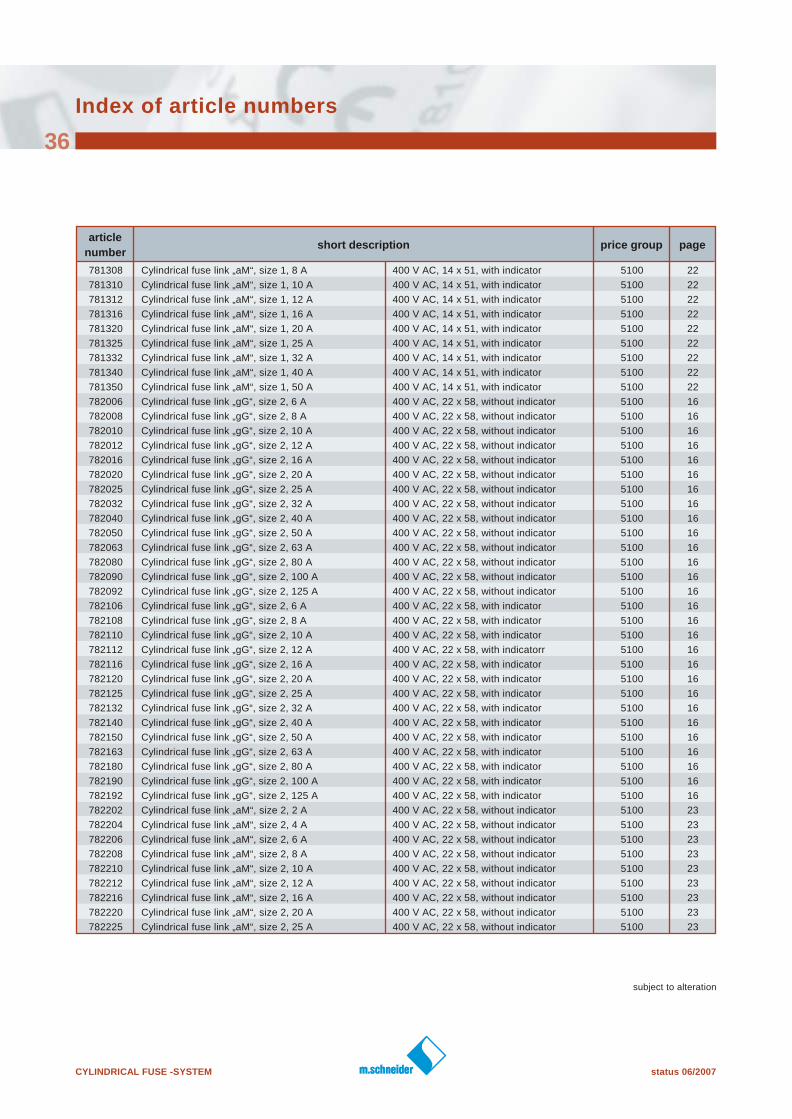
Index of article numbers
36
article
numbershort description price group page
781308 Cylindrical fuse link „aM“, size 1, 8 A 400 V AC, 14 x 51, with indicator 5100 22
781310 Cylindrical fuse link „aM“, size 1, 10 A 400 V AC, 14 x 51, with indicator 5100 22
781312 Cylindrical fuse link „aM“, size 1, 12 A 400 V AC, 14 x 51, with indicator 5100 22
781316 Cylindrical fuse link „aM“, size 1, 16 A 400 V AC, 14 x 51, with indicator 5100 22
781320 Cylindrical fuse link „aM“, size 1, 20 A 400 V AC, 14 x 51, with indicator 5100 22
781325 Cylindrical fuse link „aM“, size 1, 25 A 400 V AC, 14 x 51, with indicator 5100 22
781332 Cylindrical fuse link „aM“, size 1, 32 A 400 V AC, 14 x 51, with indicator 5100 22
781340 Cylindrical fuse link „aM“, size 1, 40 A 400 V AC, 14 x 51, with indicator 5100 22
781350 Cylindrical fuse link „aM“, size 1, 50 A 400 V AC, 14 x 51, with indicator 5100 22
782006 Cylindrical fuse link „gG“, size 2, 6 A 400 V AC, 22 x 58, without indicator 5100 16
782008 Cylindrical fuse link „gG“, size 2, 8 A 400 V AC, 22 x 58, without indicator 5100 16
782010 Cylindrical fuse link „gG“, size 2, 10 A 400 V AC, 22 x 58, without indicator 5100 16
782012 Cylindrical fuse link „gG“, size 2, 12 A 400 V AC, 22 x 58, without indicator 5100 16
782016 Cylindrical fuse link „gG“, size 2, 16 A 400 V AC, 22 x 58, without indicator 5100 16
782020 Cylindrical fuse link „gG“, size 2, 20 A 400 V AC, 22 x 58, without indicator 5100 16
782025 Cylindrical fuse link „gG“, size 2, 25 A 400 V AC, 22 x 58, without indicator 5100 16
782032 Cylindrical fuse link „gG“, size 2, 32 A 400 V AC, 22 x 58, without indicator 5100 16
782040 Cylindrical fuse link „gG“, size 2, 40 A 400 V AC, 22 x 58, without indicator 5100 16
782050 Cylindrical fuse link „gG“, size 2, 50 A 400 V AC, 22 x 58, without indicator 5100 16
782063 Cylindrical fuse link „gG“, size 2, 63 A 400 V AC, 22 x 58, without indicator 5100 16
782080 Cylindrical fuse link „gG“, size 2, 80 A 400 V AC, 22 x 58, without indicator 5100 16
782090 Cylindrical fuse link „gG“, size 2, 100 A 400 V AC, 22 x 58, without indicator 5100 16
782092 Cylindrical fuse link „gG“, size 2, 125 A 400 V AC, 22 x 58, without indicator 5100 16
782106 Cylindrical fuse link „gG“, size 2, 6 A 400 V AC, 22 x 58, with indicator 5100 16
782108 Cylindrical fuse link „gG“, size 2, 8 A 400 V AC, 22 x 58, with indicator 5100 16
782110 Cylindrical fuse link „gG“, size 2, 10 A 400 V AC, 22 x 58, with indicator 5100 16
782112 Cylindrical fuse link „gG“, size 2, 12 A 400 V AC, 22 x 58, with indicatorr 5100 16
782116 Cylindrical fuse link „gG“, size 2, 16 A 400 V AC, 22 x 58, with indicator 5100 16
782120 Cylindrical fuse link „gG“, size 2, 20 A 400 V AC, 22 x 58, with indicator 5100 16
782125 Cylindrical fuse link „gG“, size 2, 25 A 400 V AC, 22 x 58, with indicator 5100 16
782132 Cylindrical fuse link „gG“, size 2, 32 A 400 V AC, 22 x 58, with indicator 5100 16
782140 Cylindrical fuse link „gG“, size 2, 40 A 400 V AC, 22 x 58, with indicator 5100 16
782150 Cylindrical fuse link „gG“, size 2, 50 A 400 V AC, 22 x 58, with indicator 5100 16
782163 Cylindrical fuse link „gG“, size 2, 63 A 400 V AC, 22 x 58, with indicator 5100 16
782180 Cylindrical fuse link „gG“, size 2, 80 A 400 V AC, 22 x 58, with indicator 5100 16
782190 Cylindrical fuse link „gG“, size 2, 100 A 400 V AC, 22 x 58, with indicator 5100 16
782192 Cylindrical fuse link „gG“, size 2, 125 A 400 V AC, 22 x 58, with indicator 5100 16
782202 Cylindrical fuse link „aM“, size 2, 2 A 400 V AC, 22 x 58, without indicator 5100 23
782204 Cylindrical fuse link „aM“, size 2, 4 A 400 V AC, 22 x 58, without indicator 5100 23
782206 Cylindrical fuse link „aM“, size 2, 6 A 400 V AC, 22 x 58, without indicator 5100 23
782208 Cylindrical fuse link „aM“, size 2, 8 A 400 V AC, 22 x 58, without indicator 5100 23
782210 Cylindrical fuse link „aM“, size 2, 10 A 400 V AC, 22 x 58, without indicator 5100 23
782212 Cylindrical fuse link „aM“, size 2, 12 A 400 V AC, 22 x 58, without indicator 5100 23
782216 Cylindrical fuse link „aM“, size 2, 16 A 400 V AC, 22 x 58, without indicator 5100 23
782220 Cylindrical fuse link „aM“, size 2, 20 A 400 V AC, 22 x 58, without indicator 5100 23
782225 Cylindrical fuse link „aM“, size 2, 25 A 400 V AC, 22 x 58, without indicator 5100 23
status 06/2007 CYLINDRICAL FUSE -SYSTEM
subject to alteration
Index of article numbers
37
article
numbershort description price group page
782232 Cylindrical fuse link „aM“, size 2, 32 A 400 V AC, 22 x 58, without indicator 5100 23
782240 Cylindrical fuse link „aM“, size 2, 40 A 400 V AC, 22 x 58, without indicator 5100 23
782250 Cylindrical fuse link „aM“, size 2, 50 A 400 V AC, 22 x 58, without indicator 5100 23
782263 Cylindrical fuse link „aM“, size 2, 63 A 400 V AC, 22 x 58, without indicator 5100 23
782280 Cylindrical fuse link „aM“, size 2, 80 A 400 V AC, 22 x 58, without indicator 5100 23
782290 Cylindrical fuse link „aM“, size 2, 100 A 400 V AC, 22 x 58, without indicator 5100 23
782292 Cylindrical fuse link „aM“, size 2, 125 A 400 V AC, 22 x 58, without indicator 5100 23
782306 Cylindrical fuse link „aM“, size 2, 6 A 400 V AC, 22 x 58, with indicator 5100 23
782308 Cylindrical fuse link „aM“, size 2, 8 A 400 V AC, 22 x 58, with indicator 5100 23
782310 Cylindrical fuse link „aM“, size 2, 10 A 400 V AC, 22 x 58, with indicator 5100 23
782312 Cylindrical fuse link „aM“, size 2, 12 A 400 V AC, 22 x 58, with indicator 5100 23
782316 Cylindrical fuse link „aM“, size 2, 16 A 400 V AC, 22 x 58, with indicator 5100 23
782320 Cylindrical fuse link „aM“, size 2, 20 A 400 V AC, 22 x 58, with indicator 5100 23
782325 Cylindrical fuse link „aM“, size 2, 25 A 400 V AC, 22 x 58, with indicator 5100 23
782332 Cylindrical fuse link „aM“, size 2, 32 A 400 V AC, 22 x 58, with indicator 5100 23
782340 Cylindrical fuse link „aM“, size 2, 40 A 400 V AC, 22 x 58, with indicator 5100 23
782350 Cylindrical fuse link „aM“, size 2, 50 A 400 V AC, 22 x 58, with indicator 5100 23
782363 Cylindrical fuse link „aM“, size 2, 63 A 400 V AC, 22 x 58, with indicator 5100 23
782380 Cylindrical fuse link „aM“, size 2, 80 A 400 V AC, 22 x 58, with indicator 5100 23
782390 Cylindrical fuse link „aM“, size 2, 100 A 400 V AC, 22 x 58, with indicator 5100 23
782392 Cylindrical fuse link „aM“, size 2, 125 A 400 V AC, 22 x 58, with indicator 5100 23
783000 Neutral conductor, size 00 , 8,5 x 31,5 for cylindrical fuse disconnectors 5100 33
783100 Neutral conductor, size 0 ,10 x 38 for cylindrical fuse disconnectors 5100 33
783200 Neutral conductor, size 1, 14 x 51 for cylindrical fuse disconnectors 5100 33
783300 Neutral conductor, size 2, 22 x 58 for cylindrical fuse disconnectors 5100 33
784010 Fuse disconnector single pole switching for cylindrical fuse links, size 00 , 8 x 31 5100 30
784011 Fuse disconnector single pole switching + NL for cylindrical fuse links, size 00 , 8 x 31 5100 30
784020 Fuse disconnector double pole switching for cylindrical fuse links, size 00, 8 x 31 5100 30
784030 Fuse disconnector triple pole switching for cylindrical fuse links, size 00, 8 x 31 5100 30
784031 Fuse disconnector triple pole switching + NL for cylindrical fuse links, size 00, 8 x 31 5100 30
785110 Fuse disconnector single pole switching for cylindrical fuse links, size 0 ,10 x 38 5100 30
785111 Fuse disconnector single pole switching + NL for cylindrical fuse links, size 0, 10 x 38 5100 30
785120 Fuse disconnector double pole switching for cylindrical fuse links, size 0, 10 x 38 5100 30
785130 Fuse disconnector triple pole switching for cylindrical fuse links, size 0, 10 x 38 5100 30
785131 Fuse disconnector triple pole switching + NL for cylindrical fuse links, size 0, 10 x 38 5100 30
786210 Fuse disconnector single pole switching for cylindrical fuse links, size 1, 14 x 51 5100 31
786211 Fuse disconnector single pole switching + NL for cylindrical fuse links, size 1, 14 x 51 5100 31
786220 Fuse disconnector double pole switching for cylindrical fuse links, size 1, 14 x 51 5100 31
786230 Fuse disconnector triple pole switching for cylindrical fuse links, size 1, 14 x 51 5100 31
786231 Fuse disconnector triple pole switching+ NL for cylindrical fuse links, size 1, 14 x 51 5100 31
787310 Fuse disconnector single pole switching for cylindrical fuse links, size 2, 22 x 58 5100 31
787311 Fuse disconnector single pole switching + NL for cylindrical fuse links, size 2, 22 x 58 5100 31
787320 Fuse disconnector double pole switching for cylindrical fuse links, size 2, 22 x 58 5100 31
787330 Fuse disconnector triple pole switching for cylindrical fuse links, size 2, 22 x 58 5100 31
787331 Fuse disconnector triple pole switching + NL for cylindrical fuse links, size 2, 22 x 58 5100 31
CYLINDRICAL FUSE -SYSTEM status 12/2007
38
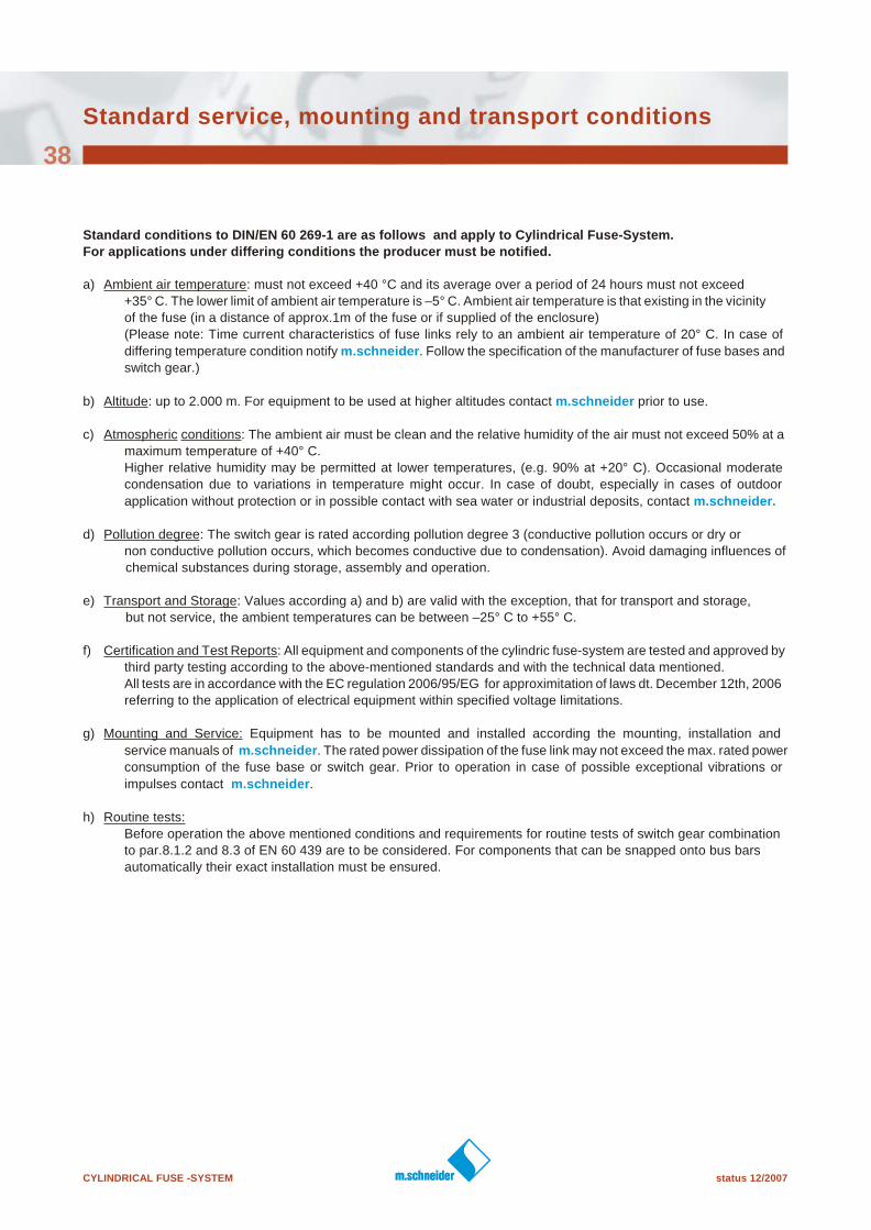
Standard conditions to DIN/EN 60 269-1 are as follows and apply to Cylindrical Fuse-System.
For applications under differing conditions the producer must be notified.
a) Ambient air temperature: must not exceed +40 °C and its average over a period of 24 hours must not exceed
+35° C. The lower limit of ambient air temperature is –5° C. Ambient air temperature is that existing in the vicinity
of the fuse (in a distance of approx.1m of the fuse or if supplied of the enclosure)
(Please note: Time current characteristics of fuse links rely to an ambient air temperature of 20° C. In case of
differing temperature condition notify m.schneider. Follow the specification of the manufacturer of fuse bases and
switch gear.)
b) Altitude: up to 2.000 m. For equipment to be used at higher altitudes contact m.schneider prior to use.
c) Atmospheric conditions: The ambient air must be clean and the relative humidity of the air must not exceed 50% at a
maximum temperature of +40° C.
Higher relative humidity may be permitted at lower temperatures, (e.g. 90% at +20° C). Occasional moderate
condensation due to variations in temperature might occur. In case of doubt, especially in cases of outdoor
application without protection or in possible contact with sea water or industrial deposits, contact m.schneider.
d) Pollution degree: The switch gear is rated according pollution degree 3 (conductive pollution occurs or dry or
non conductive pollution occurs, which becomes conductive due to condensation). Avoid damaging influences of
chemical substances during storage, assembly and operation.
e) Transport and Storage: Values according a) and b) are valid with the exception, that for transport and storage,
but not service, the ambient temperatures can be between –25° C to +55° C.
f) Certification and Test Reports: All equipment and components of the cylindric fuse-system are tested and approved by
third party testing according to the above-mentioned standards and with the technical data mentioned.
All tests are in accordance with the EC regulation 2006/95/EG for approximitation of laws dt. December 12th, 2006
referring to the application of electrical equipment within specified voltage limitations.
g) Mounting and Service: Equipment has to be mounted and installed according the mounting, installation and
service manuals of m.schneider. The rated power dissipation of the fuse link may not exceed the max. rated power
consumption of the fuse base or switch gear. Prior to operation in case of possible exceptional vibrations or
impulses contact m.schneider.
h) Routine tests:
Before operation the above mentioned conditions and requirements for routine tests of switch gear combination
to par.8.1.2 and 8.3 of EN 60 439 are to be considered. For components that can be snapped onto bus bars
automatically their exact installation must be ensured.
Standard service, mounting and transport conditions
power to the people
The companies of the m.schneider group have designed, produced and installed electro
technical products of high quality since 1926 in Annaberg - Germany, since 1946 in Vienna -
Austria and since 1996 in Sezemice - Czech Republic. About 300 employees are active in
Austria, Germany, the Czech Republic, Hungary, Poland, China and Nigeria. The companies
activities comprise:
u Production of fuses and switch gear
u Installation of electrical and digital data networks
u Technical facility management
u Telecommunication service
u Nationally certified cable test department
m.schneider is a leading international complete supplier in the field of fuse- and bus bar
systems. The product programme comprises MULTIFIX® bus bar systems, the NH-fuse
system, D0/D- and cylindrical fuse systems, miniature duse links and accessories as well as
high voltage fuse links.
In the field of NH-(low voltage high rupturing) DIN-fuse material m.schneider is a long term
specialist. The product portfolio comprises the complete NH-fuse system, EUROFUSE® fuse
links, horizontal and vertical fuse bases, MULTIBLOC® fuse switch disconnectors ans
MULTIVERT® vertical fuse switch disconnectors in many varieties as well as a wide range of
accessories. The function of our products is the protection of persons, systems and
installations agains the impact of overloads and short-circuits.
The products meet the highest quality requirements, extending the demands of national and
international standards, certified by many company held patents for products and their
assembling procedures togehter with independent test certification such as ÖVE, VDE and
CCC. All products are tested in accordance with EN, IEC.
The manufactured products are distributed i more tahn 50 countries. m. schneider was
certified to ISO 9001 in 1993 as 86th Austrian company. The company's products are
acclaimed for their reliability and are used at home and abroad by public utilities, panel board
builders and the industry.
As a leading supplier m.schneider always offers their customers in addition to regular product
training and product presentations the very bet services:
u Continuous product development and programmes
u Competent problem solving
u Latest technical standards
u Efficient customer service
u System supplier
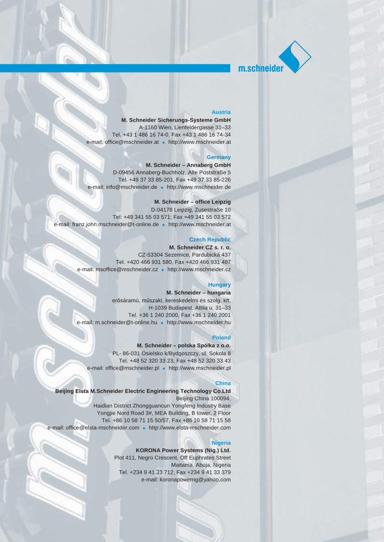
Austria
M. Schneider Sicherungs-Systeme GmbH
A-1160 Wien, Lienfeldergasse 31–33
Tel. +43 1 486 16 74-0, Fax +43 1 486 16 74-34
e-mail: [email protected] u http://www.mschneider.at
Germany
M. Schneider – Annaberg GmbH
D-09456 Annaberg-Buchholz, Alte Poststraße 5
Tel. +49 37 33 85-201, Fax +49 37 33 85-226
e-mail: [email protected] u http://www.mschneider.de
M. Schneider – office Leipzig
D-04178 Leipzig, Zusestraße 10
Tel: +49 341 55 03 571; Fax +49 341 55 03 572
e-mail: [email protected] u http://www.mschneider.at
Czech Republic
M. Schneider CZ s. r. o.
CZ-53304 Sezemice, Pardubická 437
Tel. +420 466 931 580, Fax +420 466 931 487
e-mail: [email protected] u http://www.mschneider.cz
Hungary
M. Schneider – hungaria
erÅsáramú, mászaki, kereskedelmi és szolg. kft.
H-1039 Budapest, Attila u. 31–33
Tel. +36 1 240 2000, Fax +36 1 240 2001
e-mail: [email protected] u http://www.mschneider.hu
Poland
M. Schneider – polska Spó»ka z o.o.
PL- 86-031 Osielsko k/Bydgoszczy, ul. Sokola 8
Tel. +48 52 320 33 23, Fax +48 52 320 33 43
e-mail: [email protected] u http://www.mschneider.pl
China
Beijing Elsta M.Schneider Electric Engineering Technology Co.Ltd
Beijing China 100094,
Haidian District Zhongguancun Yongfeng Industry Base
Yongjie Nord Road 3#, MEA Building, B tower, 2 Floor
Tel. +86 10 58 71 15 50/57, Fax +86 10 58 71 15 58
e-mail: [email protected] u http://www.elsta-mschneider.com
Nigeria
KORONA Power Systems (Nig.) Ltd.
Plot 411, Negro Crescent, Off Euphrates Street
Maitama, Abuja, Nigeria
Tel. +234 9 41 33 712, Fax +234 9 41 33 379
e-mail: [email protected]