fundamentals of submarine theory n. n. efimev · pdf fileunclassified ad 629 673 fundamentals...
TRANSCRIPT
UNCLASSIFIED
AD 629 673
FUNDAMENTALS OF SUBMARINE THEORY
N. N. Efimev
Department of the Navy Washington, D. C.
1966
Processed for . . .
DEFENSE DOCUMENTATION CENTER DEFENSE SUPPLY AGENCY
©ILSÄ[^OM@IH](§)yS(g FOR FtOERAL SCIENTIFIC AND TECHNICAL INFORMATION
U. S. DEPARTMENT OF COMMERCE / NATIONAL BUREAU OF STANDARDS / INSTITUTE FOR APPLIED TECHNOLOGY
UNCLASSIFIED v

Oil
fc,) Classification:
Department of the Navy
UNCLASSIFIED
Title: Fundamentals of Submarine Theory /Osnovy Teorii Podvodnykh Lodok/
Author: N. N. Yefim'yev
Page(s): 22 twp
Source: Military Publishing House of the Ministry of Difense, USSR, Moscow, 1965 pp 15-21; 62-64; 187-189; 142-145; 218-220; 265-267; 281-282; 361-365
Original Language: Russian
Translator: K
-JLZIMJ 0:^V^
Translation No,
>'^ \l
2069
. ril M
Approved by: f r K,
Reproduced by
NATIONAL TECHNICAL INFORMATION SERVICE
Springfield, Vs. 22151
Pages 15-21
Submarine Draft Marks
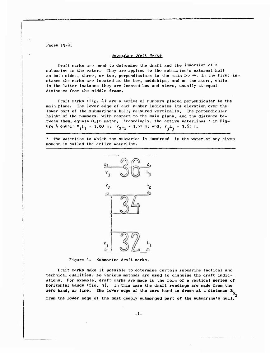
Draft marks are used to determine the draft and the immersion of a submarine in the water. They are applied to the submarine's external hull on both sides, three, or two, perpendiculars to the main plane. In the first in- stance the marks are located at the bow, amidships, and on the stern, while in the latter instance they are located bow and stern, usually at equal distances from the middle frame.
Draft marks (fig. 4) are a series of numbers placed perpendicular to the main plane. The lower edge of each number indicates its elevation over the lower part of the submarine's hull, measured vertically. The perpendicular height of the numbers, with respect to the main plane, and the distance be- tween them, equals 0.10 meter. Accordingly, the active waterlines * in Fig- ure 4 equal: V.L, - 3.20 tn; V_L„ - 3.50 m; and, V„L„ - 3.65 m. Vi 3.50 m; and, V L
♦ The waterline to which the submarine is immersed in the water at any given moment is called the active waterline.
^ ..
Figure 4. Submarine draft marks.
Draft marks make it possible to determine certain submarine tactical and technical qualities, so various methods are used to disguise the draft indic- ations. For example, draft marks are made in the form of a vertical series of horizontal bands (fig. 5)« In this case the draft readings are made from the zero band, or line. The lower edge of the zero band is drawn at a distance Z
Or
from the lower edge of the most deeply submerged part of the submarine's hull.*
-1-

The vertical distances between the lower edges of adjacent bands for the draft marks are made 0.10-0.20 meter. The zero band is made longer, or is marked with the number 0. Conventional numbers, 2, 4, etc., are placed opposite some of the bands to make reading convenient.
Waterline nn
Main plane
(Jawmian nnacxocm» L ---jf
Plane of nreatest immersion of — huil section — '
Figure 5« Concealed submarine draft marks.
In order to calculate the submarine's draft, the distance of the active wat- er line from the lower edge of the zero band at the bow, A , and stern, A , must be determined and substituted in formula (5).
= Z A, , meters . b J
A , meters s
(5)
Draft is distinguished from submergence by the magnitude Z , o1
The theoretical plan usually shows the submergence, rather than the draft. Draft immersion can be computed using the formulae in (6).
I) 1 (A, + Z ) , meters)
b o1 ' )
- Z /, - (A r (6)
Z ) , meters, 01 )
#3.
s 1 2
Submarine attitude and its determination.
A submarine's attitude is its position relative to the calm surface of the water. The position of the submarine relative to the calm surface of the water is entirely dotorrained by the active walorlinn (DVL) or the totality of such paramotor» as
T , T , T (T , T. , T ), (^ (A), and 0, o o o av b' s ' ^
where av b
y is the submarine's trim angle;
^ is the linear trim, meters;
0 is the list. -2-

Let us consider the possible cases of submarine attitudes.
1. The submarine (fig. 6) is upright, that is, has no list (0=0), and is on an even keel, that is, it has no trim ( ^/' = 0).
In this case the active waterline is parallel to the main, or base, plane. The submarine's attitude is entirely determined by its mean draft (immersion), and this, in turn, is found from the dependencies:
av
av
= T = T , meters ) o, o > b s )
T , meters s
(7)
2. The submarine is upright (0 = 0), but is trimmed by the bow or by the stern ( c/ / 0)(fig. 7) ♦. In this case the middle-line plane remains vertical, but the active waterline, V j/ L / is at some angle ^ to the base plane. The at-
titude will be characterized by the draft (immersion) at bow and stern, or by the mean draft (immersion) and trim of the suhmarino;
T , T ( f, , T ) , meters ) o, o b s v b s )
T (T ), J (A), meters o av / )
(8)
* In Figure 7, and henceforth, for convenience in depicting the situation, we will rotate the waterline by the corresponding trim angle and list, and not show the submarine with list and trim.
Trim can be measured by the angle in degrees, or in radians, as well as in linear values, such as meters, for example. The most convenient way for submar- iners to measure trim is in angular degrees, using bubble and mechanical trim angle indicators, or communicating vessel type trim angle indicators (fig. 8).
figure 6. Submarine attitude: upright and on even keel.
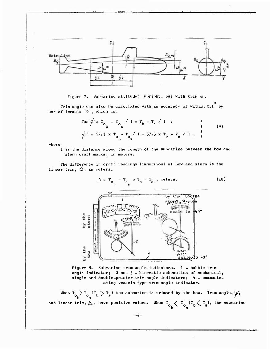
Figure 7. Submarine attitude: upright, but with trim on.
e Trim angle can also be calculated with an accuracy of within 0.1 by
use of formula (9), which is:
Tan
/'
(/;=T -T /l=T-T/l ; / o, o b s
b s
= 57.3 x T - T / 1 = 57.3 x T - T / 1 ,
) (9)
o o b s
b s
where 1 is the distance along the length of the submarine between the bow and stern draft marks, in meters.
The difference in draft readings (immersion) at bow and stern is the linear trim. A, in meters.
A = T -T =T-T, meters, o, o b s b s
(10)
"^ ^J (^
- by th; he
JL
UlKnna do'-3' scale
45c
yto ±3'
Figure 8. Submarine trim angle indicators. 1 - bubble trim angle indicator; 2 and 3 - kinematic schematics of mechanical, single and double-pointer trim angle indicators; 4 - communic-
ating vessels type trim angle indicator.
When T ^ T (T S T ) the submarine is trimmed by the bow. Trim angle, U/," b s '
and linear trim, A , have positive values. When T / T (TL ^ T ), the submarine b s
-4-
is trimmed by the stern. Trim angle, \b, and the linear trim, A i have negative values.
That attitude of the submarine in which it is upright, but with trim on is characteristic for the cruising situation in which submarines have, as a rule, a trim by the stern of from O.25 to 0.50°.
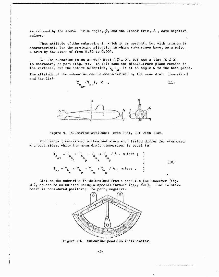
3. The submarine is on an even keel ( UJ r-. 0), but has a list (0 £ 0) to starboard, or port (fig. 9)« In this case the middle-frame plane remains in the vertical, but the active waterline, V L , is at an angle 0 to the base plane.
The attitude of the submarine can be characterized by the mean draft (immersion) and the list:
T (T ), 0 . (11) o av
av
Figure 9« Submarine attitude: even keel, but with list.
The drafts (immersions) at bow and stern when listed differ for starboard and port sides, while the mean draft (immersion) is equal to:
r = T +T +T +T / 4 , meters ; O 0,0,0 0
av b b s s s p s p
T = r av b T + T + T / 4 , meters . b s s p s p
(12)
List on the submarine is determined from a pendulum inclinometer (fig. 10), or can be calculated using a special formula (cf_. , #21), List to star- board is considered positive; to port, negative.
O
Figure 10. Submarine pendulum inclinometer.
-5-
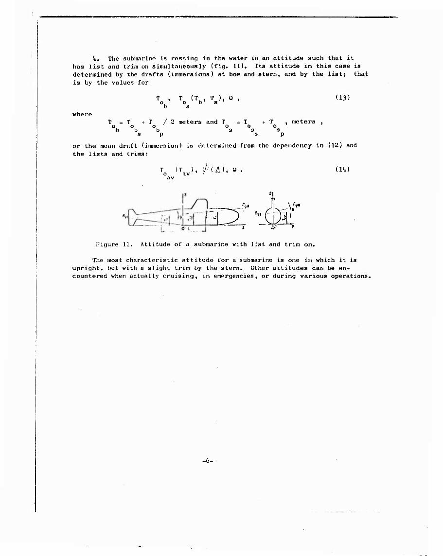
4. The submarine is resting in the water in an attitude such that it has list and trim on simultaneously (fig. 11). Its attitude in this case is determined by the drafts (immersions) at bow and stern, and by the list; that is by the values for
where
T , T (T , T ), 0 , (13) o, o b' s b s
T = T + T / 2 meters and T = T + T , meters , 0,0^0^ o o o b b b s s s
s p s p
or the mean draft (immersion) is determined from the dependency in (12) and the lists and trims:
T (T ), l/' ( A)i 0 . o av ' " M ' av
(14)
or -M ' n A» y
Figure 11. Attitude of a submarine with list and trim on.
The most characteristic attitude for a submarine is one in which it is upright, but with a slight trim by the stern. Other attitudes can be en- countered when actually cruising, in emergencies, or during various operations.
-6-
Pages 62-64
#13. Main surface and submerged conditions for submarines.
Submarines can be found in one of the following main conditions, depend- ing on the loading and filling of the main ballast tanks: diving trim at full buoyancy; trimmed down; or submerged.
When in diving trim at full buoyancy the submarine is surfaced and trimmed, the quick-diving tanks are full * and the main ballast tanks are blown.The sub- marine is in diving trim at full buoyancy, ready to submerge at any moment. The diving trim at full buoyancy condition corresponds to a cruising displacement of V in cubic motors,
r.
* The quick-diving, or tioyativc, t.'inks (TslJP) arc special tanks designed to give the submarine residual negative buoyancy during submergence, as well as trim by the bow to reduce submergence time. The weight of the water in such tanks does not enter into cruising displacement.
Diesel propelled-storage battery submarines have different diving trims at full buoyancy when carrying normal fuel and when carrying greater than normal fuel supplies.
+ V„, where V„ is the f 1 f
With a normal fuel supply the displacement is V = V c s
volume of the normal supply of fuel and lubes for assigned cruising ranges at full and economical spoods, in cubic meters, and V is the standard displacement, in cubic meters. The standard displacement is the displcicement of a completely built submarine, together with crew and fitted out with all the necessary equip- ment and supplies, with the exception of fuel and lubes.
Displacemont, V V 1 V is the displacement in diviiui trim at full c fbt ' ■'
V„, ^ is the vol- 1 bt
buoyancy with greater than normal fuel supplies on board, utne of the fuel and ballast tanks, in cubic meters. *♦
In the triiiimod down condition on the surface the submarine is trimmed and the negative tanks are blown, but the main ballast tanks are full, with the exception of the amidships group of tanks, which are blown. Displacement in the trimmed down condition is
where V , = V + V , .in cubic meters, td c mb
V is the volume of the bow and stern (or fore and aft) groups of main ballast tanks, in cubic meters.
The trimmed down condition is intermediate in the emersion when in diving trim at full buoyancy.
The submerged condition is the condition of a trimmed down submarine sub- merged with full main ballast tanks, but with the negative tanks blown. The
** The fuel-ballast tanks are the main ballast tanks which can be adapted for the storage of liquid fuel.
-7-

submerged condition corresponds to a displacement
V =V fV,=V +V^ , cubic meters, m c mb c is
where V is the volumo of the main ballast tanks, in cubic meters: mb
V. is the full submergence volume, in cubic meters, fs
When making calculation, attention must also be given to the full sub- merged displacement
V = V + V , + V, , cubic meters, nu c mb hp
where f V is the volume of all submarine hull parts into which the water can hp
penetrate, in cubic meters.
Submarines can be said to be submerged to periscope depth, to snorkel (RDP)* depth, and to depths ranging from safe to limiting, depending on the depth of the submergence.
♦ The RDP is the installation which permits use of diesel engines at periscope depth.
Periscope dopth of submergence (11 ) is that depth at which it is possible to mike periscope observations of the horizon and of the air from a submerged submarine. The depth will depend upon the type of submarine, and the sea state, and will range from 8 to 11 meters.
Si ->rkel depth (",,[,,,) is that depth at which the RDP installation will funct-
ion and at which periscope observations can be made. The depth depends upon the type of submarine. It is equal to, or less than, the periscope depth.
Safe submergence depth (H ,) is that depth at which the possibility of ■'•• sd
collision with surface ships is eliminated. It is equal to 25 to 30 meters.
Operating depth (I! ) is the deepest nubmcrgonce at which the submarine
can rotnain underway for long periods of time. The operating depth is 70 to 90% of the limiting depth.
Limiting depth (H ) is that greatest depth at which the submarine can
arrive at without way on; on the bottom, for example, or underway periodically. A submarine cannot, as a rule, be underway at its limiting depth. The reason is that submarine movement takes place with a variable trim, along some curve which is oriented with respect to the particular depth. Consequently, if the submarine is underway at its limiting depth it will submerge beyond that depth periodically, and this is not permissible in normal operations. This factor has also resulted in the necessity for assigning operating depths. The limit- ing depth for modern submarines is from 400 to 500 meters.
The designed diving depth (". ,) determines the reserve strength in the
-8-

in the submarine's pressure hull and exceeds the limiting depth by from 30 to 50%. This is the depth at which destruction of the submarine's Fressure
hull can begin. The submarine should not appear at this depth except in case of emergency.
-9-
Pages 142-1'* 5
#29. Concepts of the Experimental Determination of the Transverse Stability of Submarines.
The experimental determination of the transverse tnetacencric height (inclin- ing) is made on the lead submarine of each series in the diving trim at full buoyancy and submerged conditions. * It is usually combined with test submerg- ence and weighing. Generally speaking, transverse stability is determined by experiment only in the submerged condition for serial submarines. Surfaced stability is calculated for the lead submarine, and a correction factor is added to cover its deviation from the submarine which was tested. The correction factor is determined to be the difference in submerged stability between the test and the lead submarines.
* It is not usual to make an experimental determination of longitudinal stability.
It is recommended that the inclining experiment be done in a protected body of water, whero there are no currents, and whore thr; depth is groat enough for the submarine to submenie to porioscope depth without touching the bottom. It is permissible to put out lines at bow and stern in the longitudinal plane to hold the submarines. The lines should be slack enough not to interfere with the ex- periment. Submarine loading should be either special, or normal. Small shortages and surpluses in cargo (ballast for the inclining experiment, equipment for the experiment, etc.) are allowed for in a special list of excessive and deficient loads. It is mandatory that the submarine be weighed prior to the inclining ex- periment.
Ballast for the inclining experiment is taken on in the form of cast-iron pigs with a total weight equal to at least O.OOSV V . When determining above
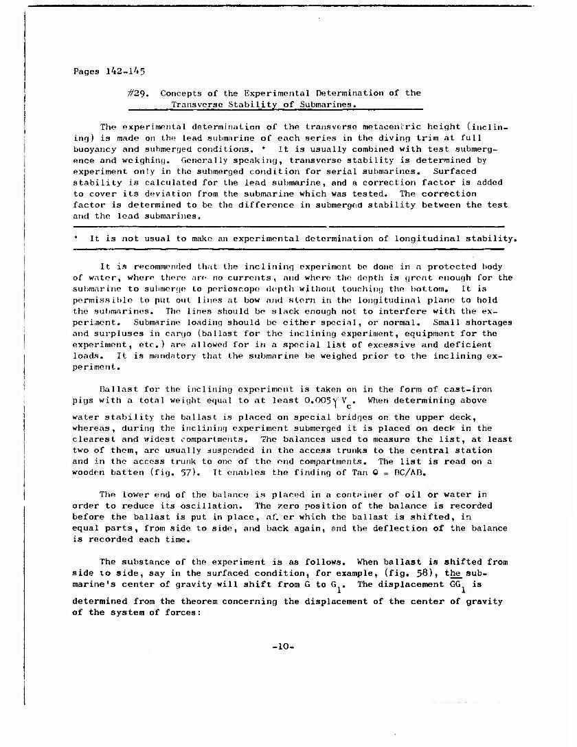
water stability the ballast is placed on special bridges on the upper deck, whereas, during the inclining experiment submerged it is placed on deck in the clearest and widest compartments. The balances used to measure the list, at least two of them, are usually suspended in the access trunks to the central station and in the access trunk to one of the end compartments. The list is read on a wooden batten (fig. 57). It enables the finding of Tan 0 = OC/AD.
The lower end of the balance is placed in a container of oil or water in order to reduce its oscillation. The zero position of the balance is recorded before the ballast is put in place, af. er which the ballast is shifted, in equal parts, from side to side, and back again, and the deflection of the balance is recorded each time.
The substance of the experiment is as follows. When ballast is shifted from side vo side, say in the surfaced condition, for example, (fig. 58)1 the_ sub- marine's center of gravity will shift from G to G , The displacement GG is
determined from the theorem concerning the displacement of the center of gravity of the system of forces:
-10-
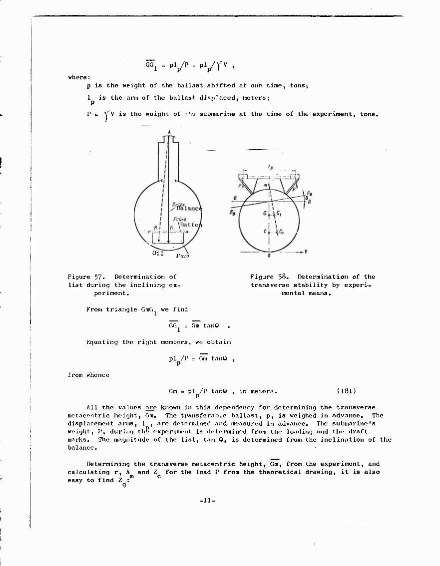
GG1 = pip/P = pip/y-v
where; p is the weight of the ballast shifted at one time, tons;
1 is the arm of the ballast dinp'aced. meters; P
P = Y"V is the weight of iu.Q submarine at the time of the experiment, tons.
Oil Macna
Figure 57. Determination of list during the inclining ex-
periment.
Figure 58. Determination of the transverse stability by experi-
mental means.
From triangle GmG we find
GG = Gm tanO .
Equating the right members, wo obtain
from whence
pi /P = Gm tanO , P
Gm = pi /P tanO , in meters, P
(181)
All the values arc known in this dependency for determining the transverse metacentric height, Gm. The transferabxe ballast, p, is weighed in advance. The displacement arms, 1 , are determined and measured in advance. The submarine's weight, P, during the experiment is determined from the loading and the draft marks. The magnitude of the list, tan 0, is determined from the inclination of the balance.
Determining the transverse metacentric height, Gm, from the experiment, and calculating r, A and Z for the load P from the theoretical drawing, it is also easy to find Z :
g
.11.
Z = Z - Citu , meters ) 9 m )
Z = Z T r - Gm , meters ) . (182)
To obtain the operable values for transverse metacentric height and for the Z-axis of the center of gravity of the submarine in the condition of_ diving trim at full buoyancy and in the submerged condition in the values for Gm and Z ob-
y tained during the experiment we introduce correction factors in accordance with the summary from the list of shortages and overages in cargo, using for these pur- poses the dependencies for determining the stability of the submarine upon receipt (consumption) of the cargoes (#22 and #26).
.12-

Pages 187-189
#40. Calculation for righting damaged submarines using the method of coutitor flooding the main bal- last tanks.
Righting (counterflooding) a damaged submarine can result in some improve- ment in its surface maneuvering qualities, and thus restore its ability to sub- merge, surface, and operate submerged. The minimum required to do this is to plug the hole and to pump out the damaged compartment.
Righting a damaged submarine envisages reducing its list and trim to values close to zero. There are three methods, or combinations of them, which can be used principally for this purpose:
shifting cargo inside the submarine;
removing the cargo;
counterflooding undamaged main ballast tanks (by taking on cargo).
The advantage in the first method is that it does not require using up any reserve buoyancy. When the second method is used reserve buoyancy is even some- what increased. The disadvantages of both of these methods are: righting takes a lot of time; use is extremely limited because there is not enough cargo to shift and throw overboard; preliminary calculations are impossible to make; the submarine's trim is upset and additional time is required to restore it when the possibility of submerging arises.
The third method calls for the use of reserve buoyancy for accomplishment. This is its basic shortcoming. Tim use of the method is limited; there are few main ballast tanks. The positive aspects of the method include: retention of submar- ine's trim; the possibility of computing righting for tall characteristic cases of casualties in advance; little time is required to right; ease of restoration of submarine's diving trim at full buoyancy by blowing full main ballast tanks.
The counterflooding method for surface ships was introduced by Admiral S. 0. Makarov as far back as 1870, lie made it mandatory on surface ships of the Russian fleet between 1903 and 1905. Thanks to the work, of I. G. Bubnov, A. N. Krylov, and V. G. Vlasov, the counter flooding method was introduced in an or- derly system of ensuring the unsinkability of surface ships and submarines, based on strict mathematical calculations.
In essence, the method involves filling undamaged main ballast tanks in order to right a damaged submarine. The tanks thus filled are opposite those causing the list and trim, and this make be due to flooded or damaged compartments and main ballast tanks. There is a simultaneous reduction in list and trim of the damaged submarine and there is less use of the reserve buoyancy. At the basis of the method is the famous instruction given by A. N. Krylov that reserve buoyancy should be used up completely and in advance of the submarine losing stability.
-13-

When counter flooding of main ballast tanks occurs there is an improvement in transverse stability, controllability, performance, and rolling conditions, the result of the use of the reserve buoyancy. In other words, there is an improve.ant in the entire complex of sea-keeping qualities for a surfaced submarine.
The following must be known in order to use the main ballast tank counter flooding .athod correctly, and in ti.aly fashion, and this applies to every case in which a casualty is involved: first, whether or not righting is necessary; second, whether it is possible, or not, to right the boat; and, third, should such counter flooding be necessary and possible, which of the main ballast tanka to flood.
The amount of list and trim determine the need for righting. usually necessary whe n the list exceeds 2.5 to ).0°, and the trim (greater trim valu s are trim by the stern). Accordingly, a list the values indicated are sufficient for righting.
Righting is 0.5 to 1.0° and trim of
The possibility of righting a damaged submarine is deter.ined by its reserve buoyancy and transverse stability. Reserve buoyancy remaining after righting should be sufficient to ensure safety of navigation. Ita magnitude is selected from the engineering docu.ents for the su~rine. The transverse stability of a damaged submarine after it has been righted should be at least equal to that of its stability in the trimmed down position.
The calculation for righting a damaged submarine by the main ballast tank counter flooding method is carried out in the following manner:
1. compute stability and draft for the da.aged suo.arine (#)9) for a number of possible cases of flooded compartments and main ballast tanks;
2. select for counter flooding those main ballast tanks such that their summed m1 and Mt will approach the list and trim moments of the co•partments
mb mb and main ballast tanks flooded as a result of the damage, and will be of opposite signs. The volume of the main ballast tanks flooded should be •inimu• for satisfying righting conditions,
). compute the stability and draft of the damaged submarine after righting (#)9). In this case the initial poeition taken is thAt for the stability and draft of the damaged submarine prior to righting.
If the results of the calculations do not satisfy the conditions which will determine righting. the boat, make a new selection ot main ballaat tanks and do the calculations again. These calculations are repeated until such ii .. aa the needed results are obtained.
-14-
Pages 218-220
//45. Tables for independent surfacing from the bottom of damaged submarines.
The tables are systemized data from calculations for independent surfac- ing of a damaged submarine with flooded compartments and damaged main ballast tanks.
Tables for independent surfacing from the bottom (Table 18) can be compiled according to tables of the type used for surface unsinkability. They should show:
types of casualties connected with the flooding of compartments in the pressure hull and with damage to main ballast tanks in the pressure hull on the same side of the submarine;
the condition of the damaged submarine on the bottom;
measures which will provide for independent surfacing (trimming, main ballast tanks which can be blown);
condition of the damaged submarine upon surfacing;
the submergence depths from which a damaged submarine can surface independ- ently with its available reserve of high pressure air
The curves which are part of the table (fig. 87) make it possible to deter- mine immediately, and without calculations of any sort, the surfacing depth and the quantity of high pressure air needed for surfacing the boat in each concrete case of damage.
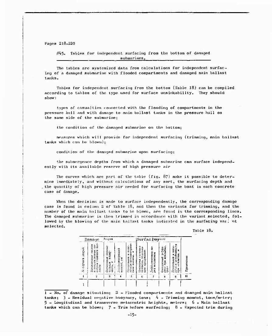
When the decision is made to surface independently, the corresponding damage case is found in column 2 of Table 18, and then the variants for trimming, and the number of the main ballast tanks to he blown, are found in the corresponding lines, The damaged submarine is then trimmed in accordance with the variant selected, fol- lowed by the blowing of the; main ballast tanks indicated in the surfacing varJ nt selected.
Table 18.
Damage Ami1"«
1
1
V S rl t =« i a» o
= * vl
c s - ' o c ai H = o ■ m :
a s s SJ
Surf ac I'm}"'
->f
0g
3 " (fl H •* - O J
1 - No. of damage situation; 2 - flooded compartments and damaged main ballast tanks; 3 - Residual negative buoyancy, tons; '1 - Trimming moment, tons/metor; 5 - Longitudinal and transverse metacontric heights, meters; 6 - Main ballast tanks which can be blown; 7 - Trim before surfacing; 8 - Expected trim during
-15-
surfacing, degrees; 9 - Longitudinal and transfer stability during surfacing,
meters; 10 - Notes.
The samo conventional symbols used in Table ik wore used here.
NOTES: 1. As wil1 be soon from the manner in which the table is con- structed, one type of damage should, as a minimum, have two surfacing variants, and each of these, in turn, should have two or more trimming variants.
2. Column 7 must contain exact information on how to trim, that is, where, and how much ballast to take on; from where, and how much, as well as what kind, of cargo to remove from the boat; the tanks between which liquid cargo is to be shifted, what kind, and how much (for example, Auxiliary Tank No. 1 - overboard 1.0 ton, etc.).
3. The calculation for stability is made in accordance with generally accepted rules for taking on cargo.
In conclusion, it should be noted that modern submarines, such as those with atomic power, for example, are capable of running at high submerged speeds for long periods of time and can be held with comparatively high values for residual neg- ative buoyancy by creating trim by the stern and by shifting the horizontal rudders accordingly (#73). This property of high-speed submarines is an important factor in ensuring submerged unsinkability and definitely causes this latter to approach optimum requirements (#42).
-16-

Pages 265-267
#55. The Speed Trials Concept.
SubDarine apeed trials are designed to determine maxi.um underway speed (on the surface, when operating on snorkel, and submerged), aa well aa to determine the dependence between underway speed, propeller shaft rpm (main engines) and .ain engine power outputs. Speed trials are also used to deter•ine fuel consumption .(or other power source utilization), lube oil consumption, etc., per mile covered at various speeds, as well aa to deterMine economical speed and cruising radius (#5)). If the submarine has the necessary gear installed propeller thrust is also ~asured.
Speed trials are conducted with all lead aub.arinea in a series, aa well · as with all submarines built outside the various series, prior to co.miaaionirig, and with sub.arines which have completed .odernization and major overhauls.
Speed trials are conducted on a course .easuring fro. ) to 5 miles in length. The measured "mile" ia a section of the sea with adequate depth and specially fitted out with ranges for departure and taking cuts required aa the test progresses. The area in which the measured "mile" ia located should have sufficient maneuvering roo• for the submarine.
The submarine is docked prior to speed trials and the hull is cleaned and paint d, while propellors ar check d for proper opcrntino condition.
Trials are made on the surface in the trimmed down condition with full ballast, under snorkel, and sub.erged to periscope depth. List is not per•itted during the trials.
The following basic measurements are .ade during the trials.
First, underway speed relative to the water, in accordance with the markers along the course, is determined. A atop watch ia used to record the time of the run over the course. At least three runs are .ade; to eliminate the effects of current. '~'to runs are ~~ade in one direction, one in the oppoa_ite direction. True apeed ia deter.ined from the dependency
. ()07)
ia the length of the .easured "•ile" 4n miles;
t2
and t3
are the times for the firat, second, and third runa over the measured "•i le" in hours.
Second, the abaft rpm are recorded. Revolut ion• made on each run can be cletenained froia the revolution counter, or with contact ringa. 1be true .,.., n, can be detenained fro. the dependency
n = o.25(nl • 2n2 • n)) ' ..... t ()o8)
-17-
NP n jtr. Uö/MUH
N , n1 e hp
rpm n = f(v , ) ,. .sub
N =fT(v . ) e I sub
ve»f,f%| v , , knots
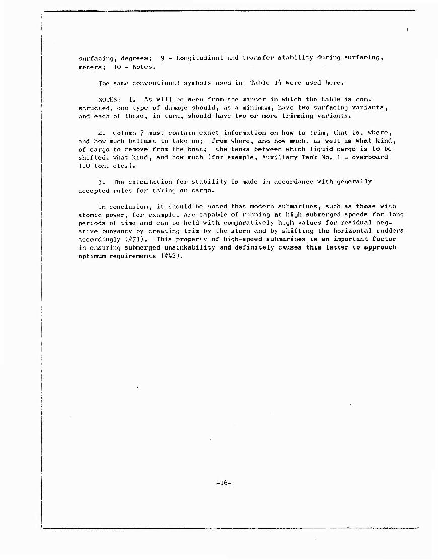
Figure 106. Dopendonco of power and rpm on submarine's underway speed.
where n , n , and n are the rpm on the first, second, and third runs, rpm.
i & j
Third, the main engine power outputs are measured. Power output is deter- mined using torsiographing, indicating, or other means which can be used, on each run. True power, N, is found from the dependence similar to that shown as formula (308).
Fourth, fuel consumption (or other power source consumption) is determined per mile covered at the givon speed. True fuel consumption, qv,, per mile can M be obtained from a depcmdency .similar to that shown in formula (308).
Fifth, propeller thrust is measured, if the necessary gear is available in the submarine.
The results of the speed trials are processed to compile tables and to construct curves for surface, snorkel, and submerged runs: (l) for power and rpm according to underway speed on the surface and submerged (for surface run- ning, figure 106, for example); (2) for fuel (or other power source) consumpt- ion per mile according to speed and main engine combination used; (3) cruis- ing radius according to speed and main engine combination used, etc.
It is recommended that speed trials be run without interruptions, and that they be run off when the weather is good (wind force no higher than two and sea state no highor than one), in order to eliminate the effects of outside condit- ions.
.18-

Pages 281-282
Chapter XI
Submarine Control in the Horizontal Plane
i^6l. General Concepts and Determination.
By control in the horizontal plane is understood to mean the ability of a submarine to maintain a given course and to be able to change that course by the use of the vertical rudder and the propellers. Control in the horizontal plane is an extremely important soa-keeping quality for a submarine. It makes it possible to carry out all maneuvers in the horizontal plane needed to carry out the combat missions assigned submarines.
The general behavior patterns in the control of a submarine in the horizon- tal plane are the same as those for the surface ship. However, and as distin- guished from the surface ship, the submarine must have control in the horizontal plane not only on the surface, but when submerged, when surfacing, and v/hen sub- merging. Since the processes of submerging and surfacing are of brief duration, and since the behavior patterns involved in control in the horizontal plane are similar for all positions in which the submarine can be found, we will consider submarine control in the surfaced and submerged conditions only.
Submarine control in the horizontal plane is the sum of the steadiness on course (steadiness of movement in the horizontalplane) and turning ability.
Steadiness on course is that ability of submarines to move on a straight line along an assigned course when the rudder is amidships.
Turning ability is that ability of submarines to clmnge course as a result of the effects of the vortical rudder and the propellers.
As we can see, the requirement for steadiness on course and for turning ability are mutually contradictory. Therefore, what is required is that com- bination of the qualities-noted which will, to the greatest extent possible, provide the tactical requirement for submarine maneuvering qualities for the particular class and type, and thus provide the submarine with good control in the horizontal plane.
Immediate note should be made of the fact that the submarine, by itself, is not steady on course any more than is the surface ship. The vertical n der must be shifted constantly to hold the submarine on course. The usual sideration is that steadiness on course is adequate when the helmsman shil the rudder +2 to 3° (to starboard or port) not more than 8 to 10 times per min- ute.
Thus, the primary organ providing control in the horizontal plane is the vertical rudder. However, in multi-shaft main propulsion installations the propellers can, to some degree, provide control in the horizontal plane. Lim- ited control in the horizontal plane can be exercised with other, special, methods, such as creating a list and by the actions of the horizontal rudders.
-19-
Pages 361-365
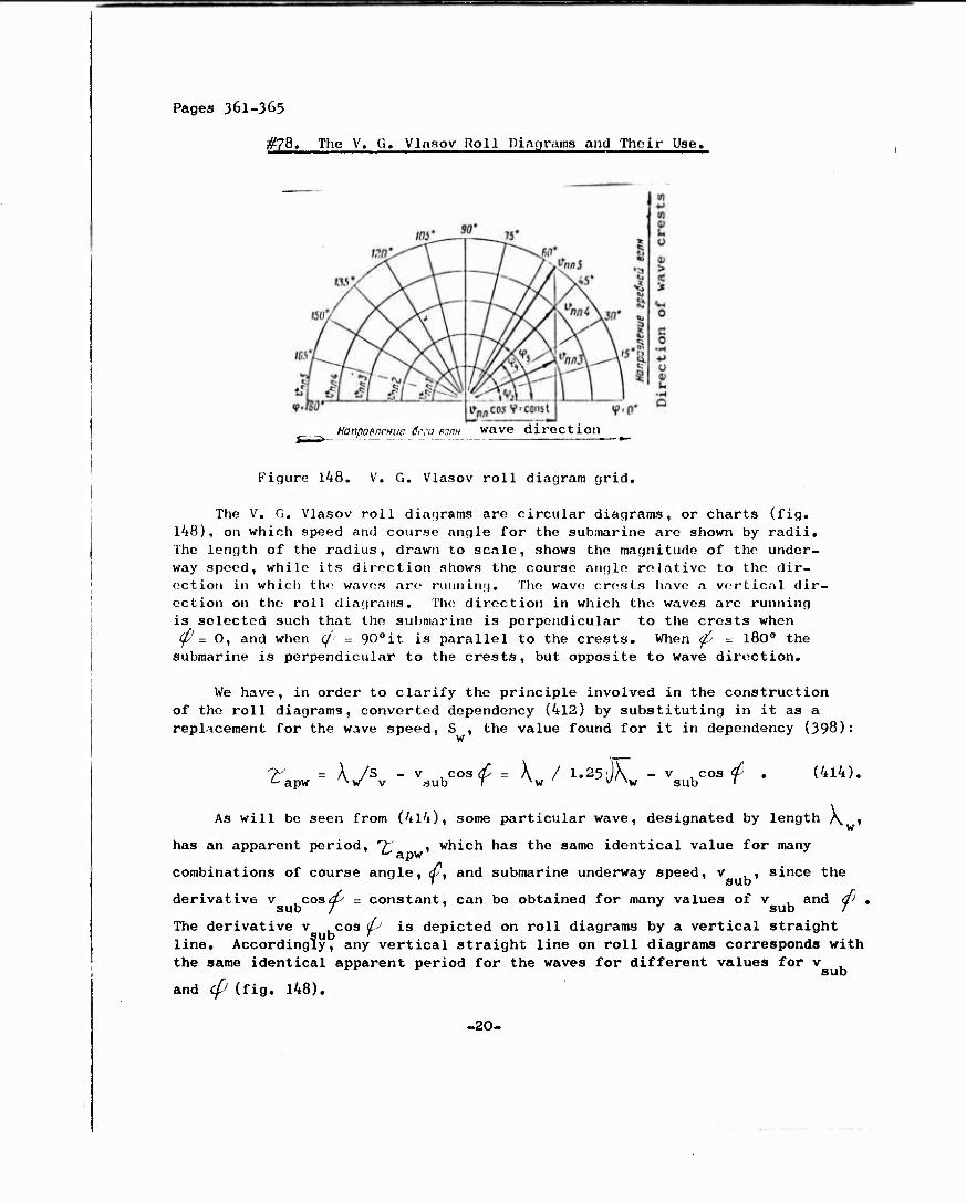
i^78. The V. G. Vlasov Roll Diagranffl and Thoir Use.
HonpoMCHuc ö,\-a eoPH wave direction
Figure 148. V. G. Vlasov roll diagram grid.
The V. G. Vlasov roll diagrams are circular diagrams, or charts (fig. 148), on which speed and course angle for the submarine are shown by radii. The length of the radius, draw?i to scale, shows the magnitude of the under- way speed, while its direction shows the course angle relative to the dir- ection in which the waves are running. The wave crests have a vertical dir- ection on the roll diagrams. The direction in which the waves are running is selected such that the submarine is perpendicular to the crests when ^=0, and when (/' = 90oit is parallel to the crests. When ^ = l80o the submarine is perpendicular to the crests, but opposite to wave direction.
We have, in order to clarify the principle involved in the construction of the roll diagrams, converted dependency (412) by substituting in it as a replacement for the wave speed, S , the value found for it in dependency (398):
w
7- = A /S - v ^cosc^' = X / 1.25 JX - v cos <p . (414). c apw ^vr v sub T xw ^ V sub '
As will be seen from (4l4), some particular wave, designated by length \ ,
has an apparent period, "^ , which has the same identical value for many
combinations of course angle, cf, and submarine underway speed, v , since the
derivative v coads = constant, can be obtained for many values of v and ^ .
The derivative v .cos & is depicted on roll diagrams by a vertical straight line. Accordingly, any vertical straight line on roll diagrams corresponds with the same identical apparent period for the waves for different values for v
and Cp (fig. 148).
-20-
However roll diagrams do not include scales for the wave periods or for submarine roll periods. In order to draw some value for the apparent period for the waves, ^r , on the diagram we must find the corresponding apparent
pariod for submarine underway speed when d = 0, using 6quation (4l4). Then, assigning values to 't , we find the underway speed, v , corresponding and
plot them on the horizontal base of the diagram. Erecting perpendiculars at the points thus obtained, we get all the possible variants for the relationship of v and d- for the given value of "T" on them, sub j * (_ apV
Solvihg equation (4l4) with respect to v . , we find sub
v , = 1.25(IX - A /?-' » meters/second , (4l5) sub ^ w v v '- apw
or, expressing v , in knots (l knot - 0.515 motors/second), sub
v , - 1.94(1.25 l/A - \ // ), knots . (4l6) sul) w w '■apw
We can obtain positive and negative values for submarine speed when making the computations. Positive values for the speed are plotted from the center of the diagram to the right, while the negatives are plotted to the left.
The same identical length of a wave correlates to two zones of greatest roll and pitch, located symmetrically relative to the speed of the submarine v , and equal to the wave speed, S : sub w
or v . s u b
= 3 = 1.25 ./A i meters/second (41?) w ^ w
v , ■= S = 2.425, A , knots . (418) sub w LMw
Since every V. G. Vlasov roll diagram corresponds with a completely defined wave length, hydrological data for a given theatre, or geographic region, can be used to select average values for wave lengths, /V , say 4, 5i 6, 7i and 8, on
w the wave scales, and used to construct roll diagrams for such values of A when
w the submarine will be operating in the theatre or region.
It is not expedient to modify roll diagrams for change in submarine loading. The submarine compensates for cargo used, or taken on. The slight changes in stability occasioned by the changes in load distributions and moments of inertia of the submarine's mass have no morked effect on the nature of its rolling.
Heaviest roll and pitch arc noted at resonance: that is, when '> = +T * »it, apW - e
and when <ys = ± T d , Pitching is particularly heavy when wave lengths are
A = (1.10 to 1.15)1" Conventional zones of heavy rolling lie within the lim-
its 7: = ±(0.80 to 1.20)T and >- = ±(0.85 to 1.15)T dj . Calculating 12 ^ apw 9 ^ apw ff a
values of ^ for submarine speed, v ,, and plotting the zones of heaviest apw sub
roll and pitch on the diagram with conventional hatching, we obtain a V, G. Vlasov roll diagram (fig. 149) for the given wave length, \ , and the sea state in the units used to designate such state.
-21-

-tvt-.i Ezzzza
X- M. l^9• . CCH. Tg,' ^..»A
Figure l'i9. V. (i. Vlisov roll diagram.
For practical use, it is recommended that all roll diagrams be constructed
on tracing paper to the same scale, aid that below each diagram the zones of
heavy roll for the nearest long lengths of waves be indicated. Then, by applying
one diagram to another, there is no difficulty in determining the nature of the
change in the zone of heavy rolling when wave motion increases, and decreases.
Naked eye interpolation can be made for the case of wave motion not shown on the
diagrams, should the need arise.
The roll diagram in each concrete case is selected for the wave length
corresponding to the sea state on the scale. A point corresponding to the sub-
marine's underway speed and course angle, say point A ^ig. l49), is plotted on
the roll diagram. The position of point A with respect to the heavy rolling zone
indicates the situation in which the submarine is found.
Rolling increases markedly upon approaching a zone of heavy rolling and
takes on its most intensive form in such zone. Consequently, when steaming and
maneuvering the submarine must, in so far as possible, avoid zones of heavy roll
and pitch, and particularly the upper sections of the zones of heavy roll and the
lower parts of zones of heavy pitching. When a submarine enters the upper sect-
ion of a heavy roll zone the result is the appearance of great oscillations in
roll (list), as a result of which the spilling of electrolyte from the storage
batteries, as well as other incidents, are possible. When the submarine enters
the lower part of a zone of heavy pitching it will take great amounts of water
over the upper deck as it. buries its bow and then its stern. There is then the
possibility of water entering the hull through open hatches and trunks. Water
can cause reduction in insulation and short circuits.
In taking steps to reduce roll it must be remembered that displacement of
the submarine along the radius, that is, increasing or decreasing speed without
changing course, has little effect on the nature of roll and pitch. The most
advantageous speed is that corresponding to the dividing line. Change in the
course angle in the ranges of 0 to 45° and 135 to l800 has a marked effect on
roll, reducing it when submarine course angles approach 0 and 180°, but there
is little effect on pitch. Change in the course angle within limits of from
-22-

45 to 135° has a marked effect on pitch, reducing it as the course angle approaches 90°. When the waves are high high submarine speeds should be avoided, particular- ly when heading into the sea (course angle ty = 180°), for this can result in the waves striking the submarine's hull with great force.
When it is necessary to change speed and course angle, and in order to eval- uate the maneuver which will take place, from the point of view of obtaining an acceptable roll, the corresponding roll diagram is selected, the point correspond- ing with the speed and course angle is plotted for the before and after values, and the change in submarine roll is noted. Then the submarine's course is plot- tod on the diagram, changing its speed and course angle so as, in so far as is possible, to avoid zones of heavy rolling, or to pass through them at their least dangerous sections, which, for the heavy roll zone is the lower sction, and, for the heavy pitch zone is the upper section.
.23-