fundamentals of rotating detonation - · pdf file2d numerical analysis of flowfield...
TRANSCRIPT
Fundamentals of Rotating Detonation Fundamentals of Rotating Detonation
Toshi Fujiwara (Nagoya University)Toshi Fujiwara (Nagoya University)

New experimental resultsNew experimental results
CylindicalCylindical channel D=140/150mmchannel D=140/150mmHydrogen Hydrogen –– air;air; ppoo =1.0bar=1.0bar
Professor Professor PiotrPiotr WolanskiWolanski
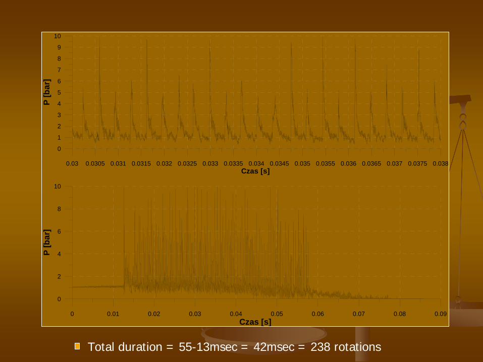
0 0.01 0.02 0.03 0.04 0.05 0.06 0.07 0.08 0.09Czas [s]
0
2
4
6
8
10
P [b
ar]
0.03 0.0305 0.031 0.0315 0.032 0.0325 0.033 0.0335 0.034 0.0345 0.035 0.0355 0.036 0.0365 0.037 0.0375 0.038Czas [s]
0
1
2
3
4
5
6
7
8
9
10
P [b
ar]
Total duration = 55-13msec = 42msec = 238 rotations
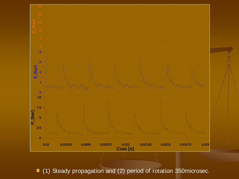
0.02 0.02025 0.0205 0.02075 0.021 0.02125 0.0215 0.02175 0.022Czas [s]
0
2.5
5
7.5
10
P 1 [b
ar]
0
2
4
6
8
P 2 [b
ar]
0
4
8
12
16
20
P 3 [b
ar]
(1) Steady propagation and (2) period of rotation 350microsec.

Rotating Detonation Engine (RDE)Rotating Detonation Engine (RDE)
Detonation engines:Detonation engines:
Higher energy release rate, higher thermodynamic efficiency, andHigher energy release rate, higher thermodynamic efficiency, and easier scaling easier scaling compared with conventional engines using deflagration.compared with conventional engines using deflagration.
Applicable to spaceplanes or highApplicable to spaceplanes or high--speed airplanes.speed airplanes.
Standing Detonation Engine:Standing Detonation Engine:
Continuous injection of combustible gas = simple system.Continuous injection of combustible gas = simple system.
Injection velocity is strictly limited (faster than CJ value) = Injection velocity is strictly limited (faster than CJ value) = narrow narrow operating conditions.operating conditions.
Pulse Detonation Engine (PDE):Pulse Detonation Engine (PDE):
Wide operating conditions (flight Mach number = 0~5).Wide operating conditions (flight Mach number = 0~5).
Repetitive and intermittent thrust = complicated system for fastRepetitive and intermittent thrust = complicated system for fast purging purging and refilling.and refilling.
Rotating Detonation Engine (RDE):Rotating Detonation Engine (RDE):
Simple configuration and higher thrust due to continuous injectiSimple configuration and higher thrust due to continuous injection.on.
Wide operating conditions without limitation of injection velociWide operating conditions without limitation of injection velocity.ty.
FlowfieldFlowfield in RDE is unknown, could be complicated and yet in RDE is unknown, could be complicated and yet is absolutely necessary for application to thrusters. is absolutely necessary for application to thrusters.
RDE has advantages, but
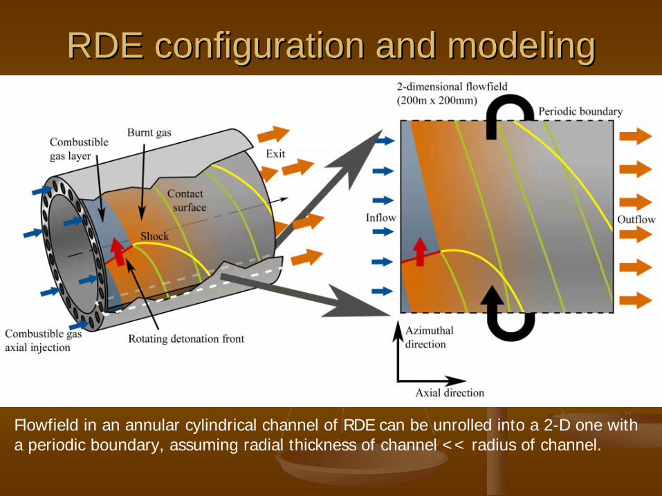
RDE configuration and modelingRDE configuration and modeling
Flowfield in an annular cylindrical channel of RDE can be unrolled into a 2-D one witha periodic boundary, assuming radial thickness of channel << radius of channel.
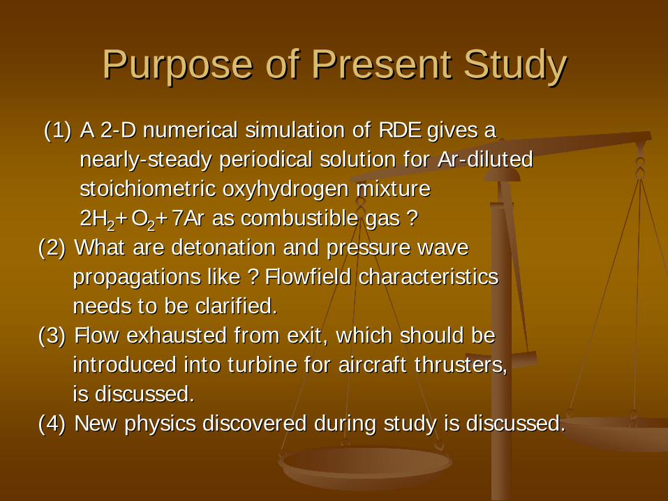
Purpose of Present StudyPurpose of Present Study(1) A 2(1) A 2--D numerical simulation of RDE gives aD numerical simulation of RDE gives a
nearlynearly--steady periodical solution for steady periodical solution for ArAr--diluteddilutedstoichiometricstoichiometric oxyhydrogen mixtureoxyhydrogen mixture2H2H 22 +O+O 22 +7Ar as combustible gas ?+7Ar as combustible gas ?
(2) What are detonation and pressure wave(2) What are detonation and pressure wavepropagations like ? propagations like ? FlowfieldFlowfield characteristicscharacteristicsneeds to be clarified.needs to be clarified.
(3) Flow exhausted from exit, which should be(3) Flow exhausted from exit, which should beintroduced into turbine for aircraft thrusters, introduced into turbine for aircraft thrusters, is discussed.is discussed.
(4) New physics discovered during study is discussed.(4) New physics discovered during study is discussed.
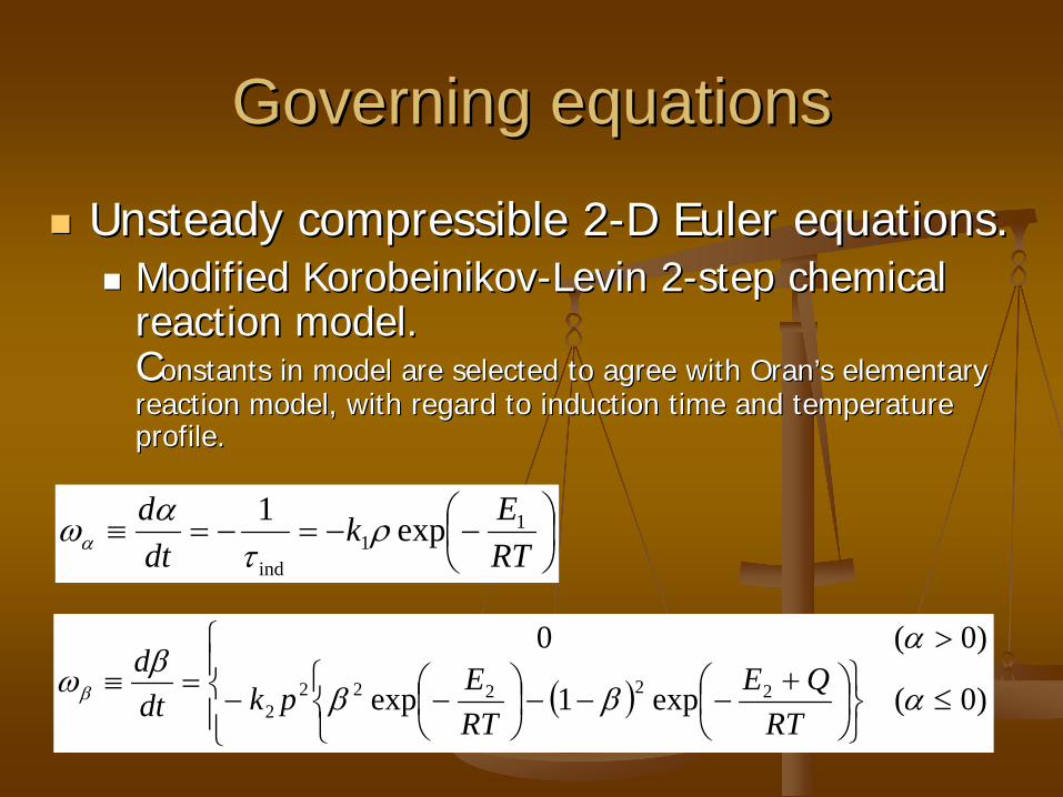
Governing equationsGoverning equations
Unsteady compressible 2Unsteady compressible 2--D Euler equations.D Euler equations.
Modified KorobeinikovModified Korobeinikov--Levin 2Levin 2--step chemical step chemical reaction model.reaction model. CConstants in model are selected to agree with Oranonstants in model are selected to agree with Oran’’s elementary s elementary reaction model, with regard to induction time and temperature reaction model, with regard to induction time and temperature profile.profile.
RTEk
dtd 1
1ind
exp1
)0(exp1exp
)0(022222
2
RTQE
RTEpkdt
d
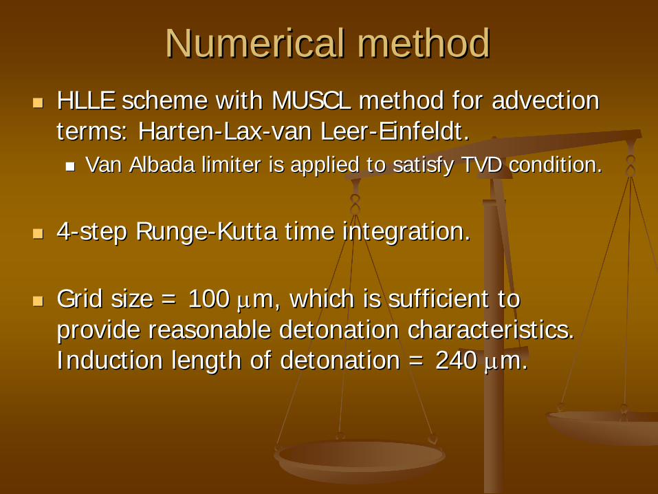
Numerical methodNumerical method
HLLE scheme with MUSCL method for advection HLLE scheme with MUSCL method for advection terms: Hartenterms: Harten--LaxLax--van Leervan Leer--Einfeldt.Einfeldt.
Van Albada limiter is applied to satisfy TVD condition.Van Albada limiter is applied to satisfy TVD condition.
44--step Rungestep Runge--Kutta time integration.Kutta time integration.
Grid size = 100 Grid size = 100 m, which is sufficient to m, which is sufficient to provide reasonable detonation characteristics.provide reasonable detonation characteristics. Induction length of detonation = 240 Induction length of detonation = 240 m.m.
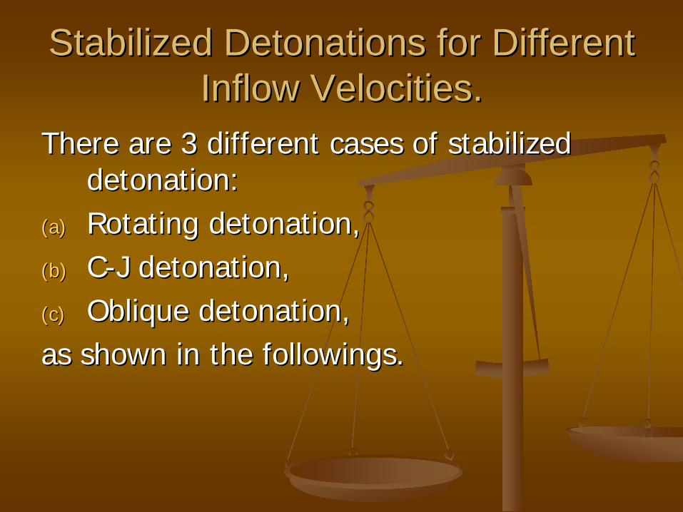
Stabilized Detonations for Different Stabilized Detonations for Different Inflow Velocities. Inflow Velocities.
There are 3 different cases of stabilized There are 3 different cases of stabilized detonation:detonation:
(a)(a) Rotating detonation,Rotating detonation,(b)(b) CC--J detonation,J detonation,(c)(c) Oblique detonation,Oblique detonation,as shown in the followings.as shown in the followings.

(a) (a) Rotating Detonation: 0 < B < D = (ARotating Detonation: 0 < B < D = (A22 + B+ B22))1/21/2 < < DcjDcj Inflow velocity of combustible mixture is Inflow velocity of combustible mixture is subdetonativesubdetonative..

(b) Standing Normal Detonation: B = (b) Standing Normal Detonation: B = DcjDcj,, Inflow velocity of combustible mixture is equal to Inflow velocity of combustible mixture is equal to DcjDcj..
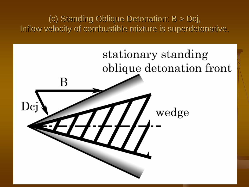
(c) Standing Oblique Detonation: B > (c) Standing Oblique Detonation: B > DcjDcj,, Inflow velocity of combustible mixture is Inflow velocity of combustible mixture is superdetonativesuperdetonative..
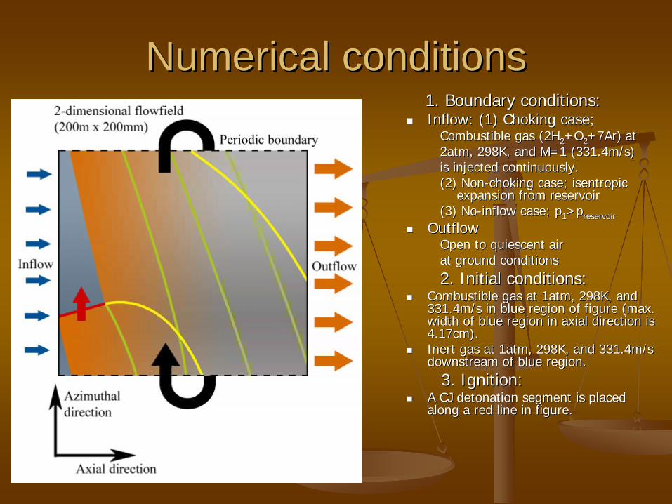
Numerical conditionsNumerical conditions1. Boundary conditions:1. Boundary conditions:
Inflow: (1) Choking case;Inflow: (1) Choking case;Combustible gas (2HCombustible gas (2H 22 +O+O 22 +7Ar)+7Ar) atat2atm, 298K, and M=1 (331.4m/s)2atm, 298K, and M=1 (331.4m/s)is injected continuously.is injected continuously.(2) Non(2) Non--choking case; isentropic choking case; isentropic
expansion from reservoirexpansion from reservoir(3) No(3) No--inflow case; pinflow case; p 11 >>pp reservoirreservoir
OutflowOutflowOpen to quiescent air Open to quiescent air at ground conditionsat ground conditions2. Initial conditions:2. Initial conditions:
Combustible gas at 1atm, 298K, and Combustible gas at 1atm, 298K, and 331.4m/s in blue region of figure (max. 331.4m/s in blue region of figure (max. width of blue region in axial direction is width of blue region in axial direction is 4.17cm).4.17cm).
Inert gas at 1atm, 298K, and 331.4m/s Inert gas at 1atm, 298K, and 331.4m/s downstream of blue region.downstream of blue region.
3. Ignition:3. Ignition:
A CJ detonation segment is placed A CJ detonation segment is placed along a red line in figure.along a red line in figure.

Development of Development of flowfieldflowfield in Model RDEin Model RDE
At nearly 1ms after ignition, a detonation rotating azimuthally in channel is seen to propagate steadily.
A detailed triple- shock structure is seen on detonation wavelet.

Flow structure in model RDEFlow structure in model RDE
Inflow
Combustible gas does not burnin spite of its contact with high-temperature burnt gas,because of very fast rotation.
Combustible gas injection is suppressedhere due to high pressure right behindrotating detonation.
Burnt gas (>1000K)
Contactsurface
Shock wave
Outflow
Detonationfront
Combustiblegas layer
Expansionfan
Inflow

Structure of unburnt gas at t=6298.5sec (during steady rotation). Brokenline gives an assumed profile for choking injection where flowfield pressureis low enough to satisfy choking condition between reservoir and flowfield. Inreality choking never happens.
Outline of Combustible Gas Layer: K-H Instability is seen.
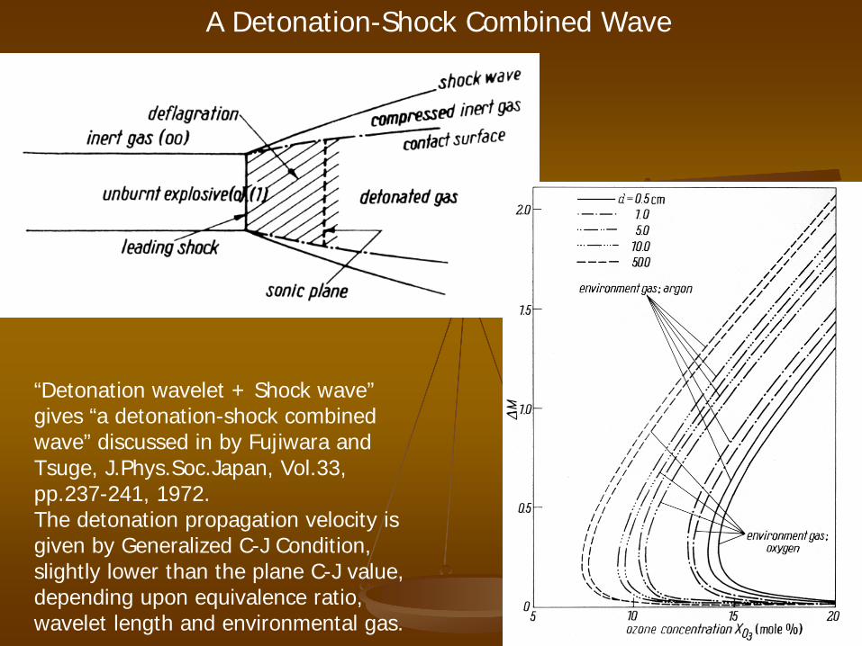
“Detonation wavelet + Shock wave” gives “a detonation-shock combined wave” discussed in by Fujiwara and Tsuge, J.Phys.Soc.Japan, Vol.33, pp.237-241, 1972. The detonation propagation velocity is given by Generalized C-J Condition, slightly lower than the plane C-J value, depending upon equivalence ratio, wavelet length and environmental gas.
A Detonation-Shock Combined Wave
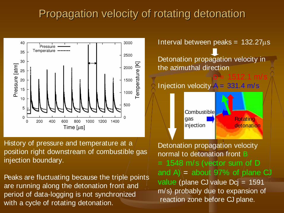
Interval between peaks = 132.27s
Detonation propagation velocity in the azimuthal direction
D = 1512.1 m/sInjection velocity A = 331.4 m/s
Detonation propagation velocity normal to detonation front B= 1548 m/s (vector sum of D and A) = about 97% of plane CJ value (plane CJ value Dcj = 1591 m/s) probably due to expansion ofreaction zone before CJ plane.
Propagation velocity of rotating detonationPropagation velocity of rotating detonation
History of pressure and temperature at a position right downstream of combustible gas injection boundary.
Peaks are fluctuating because the triple points are running along the detonation front and period of data-logging is not synchronized with a cycle of rotating detonation.
Combustiblegasinjection
Rotatingdetonation

SmokeSmoke--foil record written by triple shocks in rotating detonation aftefoil record written by triple shocks in rotating detonation after r t=6250ms (during steady rotation), where white lines are trajectt=6250ms (during steady rotation), where white lines are trajectories of ories of pressure higher than 60atm during detonation propagation. Cell spressure higher than 60atm during detonation propagation. Cell size is ize is
33--3.5mm near injection wall, while 4mm in downstream side.3.5mm near injection wall, while 4mm in downstream side.

Temporal variation of two velocities densityTemporal variation of two velocities density-- averaged over exit plane: Angular momentum is averaged over exit plane: Angular momentum is
conservedconserved

Temporal variation of ratio between densityTemporal variation of ratio between density--averaged averaged azimuthalazimuthal and axial velocities at exit plane and axial velocities at exit plane –– order of 3 %: order of 3 %:
Angular momentum is conserved.Angular momentum is conserved.
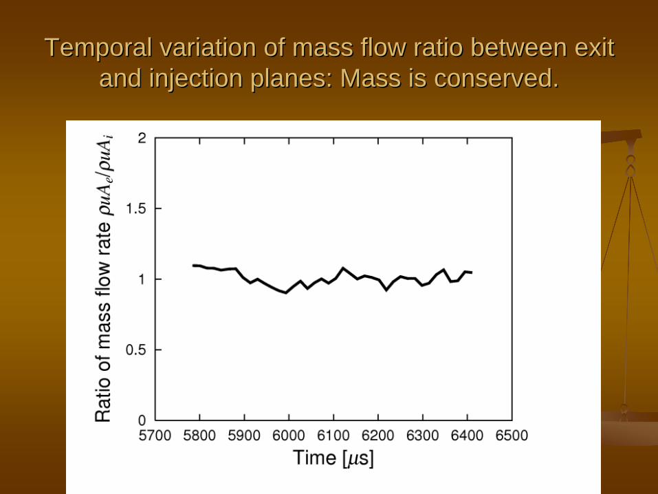
Temporal variation of mass flow ratio between exit Temporal variation of mass flow ratio between exit and injection planes: Mass is conserved.and injection planes: Mass is conserved.

Distribution of pressure Distribution of pressure along azimuthal directionalong azimuthal direction
On exit plane, a strong shock followed by expansion wave (red line) still propagates azimuthally. This shock wave weakens toward downstream, changing into a Mach wave far downstream.

Distribution of temperature Distribution of temperature along azimuthal directionalong azimuthal direction
This temperature distribution rotates at a speed near CJ value. Then a turbine, if located behind channel exit, is exposed to a high-frequency (about 7560Hz in this case) temperature fluctuation.
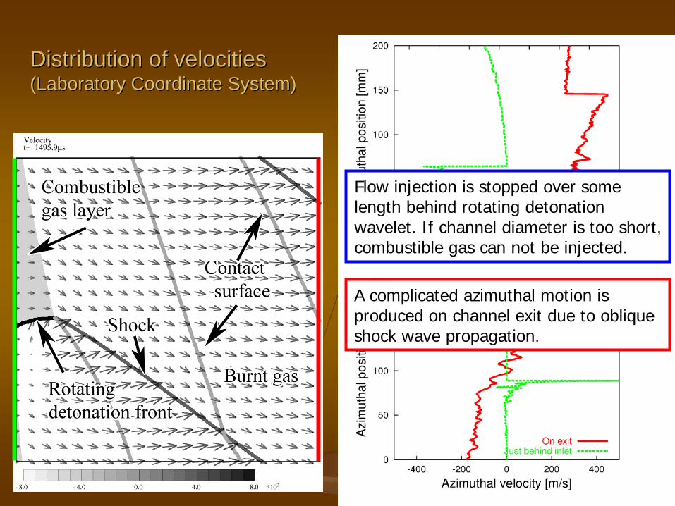
Distribution of velocities Distribution of velocities (Laboratory Coordinate System)(Laboratory Coordinate System)
A complicated azimuthal motion is produced on channel exit due to oblique shock wave propagation.
Flow injection is stopped over some length behind rotating detonation wavelet. If channel diameter is too short, combustible gas can not be injected.

Flowfield in Wave Coordinate where detonation front is fixed.

Axial velocity distributions on two planes (injection Axial velocity distributions on two planes (injection wall, exit plane) at t=6298.5msec (during steady wall, exit plane) at t=6298.5msec (during steady
rotation): 600rotation): 600--900m/sec on exit.900m/sec on exit.
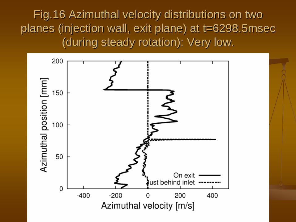
Fig.16 Fig.16 AzimuthalAzimuthal velocity distributions on two velocity distributions on two planes (injection wall, exit plane) at t=6298.5msec planes (injection wall, exit plane) at t=6298.5msec
(during steady rotation): Very low.(during steady rotation): Very low.
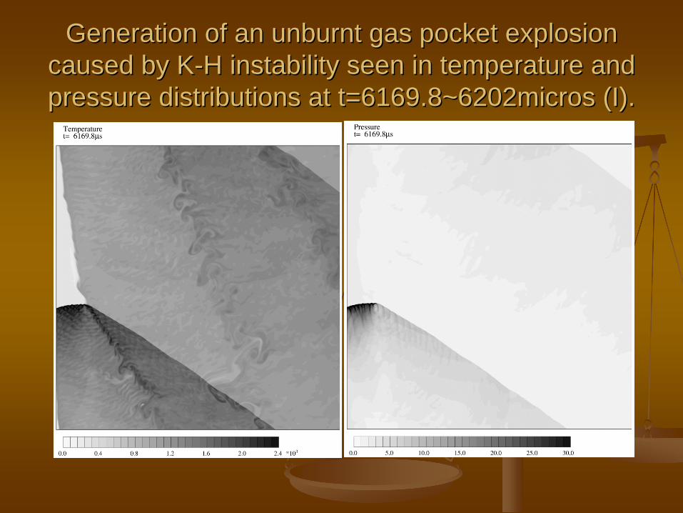
Generation of an Generation of an unburntunburnt gas pocket explosion gas pocket explosion caused by Kcaused by K--H instability seen in temperature and H instability seen in temperature and pressure distributions at t=6169.8~6202micros (I).pressure distributions at t=6169.8~6202micros (I).
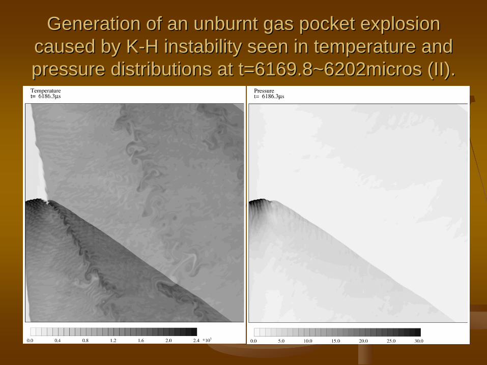
Generation of an Generation of an unburntunburnt gas pocket explosion gas pocket explosion caused by Kcaused by K--H instability seen in temperature and H instability seen in temperature and pressure distributions at t=6169.8~6202micros (II).pressure distributions at t=6169.8~6202micros (II).
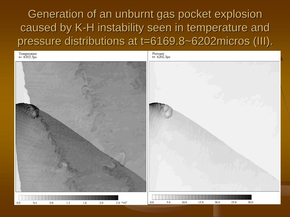
Generation of an Generation of an unburntunburnt gas pocket explosion gas pocket explosion caused by Kcaused by K--H instability seen in temperature and H instability seen in temperature and pressure distributions at t=6169.8~6202micros (III).pressure distributions at t=6169.8~6202micros (III).

Influence of lower injection velocities on Influence of lower injection velocities on existence of rotating detonation is testedexistence of rotating detonation is tested
Injection Mach number=0.25 Injection Mach number=0.5
In either cases, a detonation wavelet is separated into a shock wave and an ensuing deflagration, and is unable to propagate steadily: Quenching.

Performance of RDE as thruster: Temporal variations of thrust per unit depth (60000N/m) and specific impulse (4700sec).
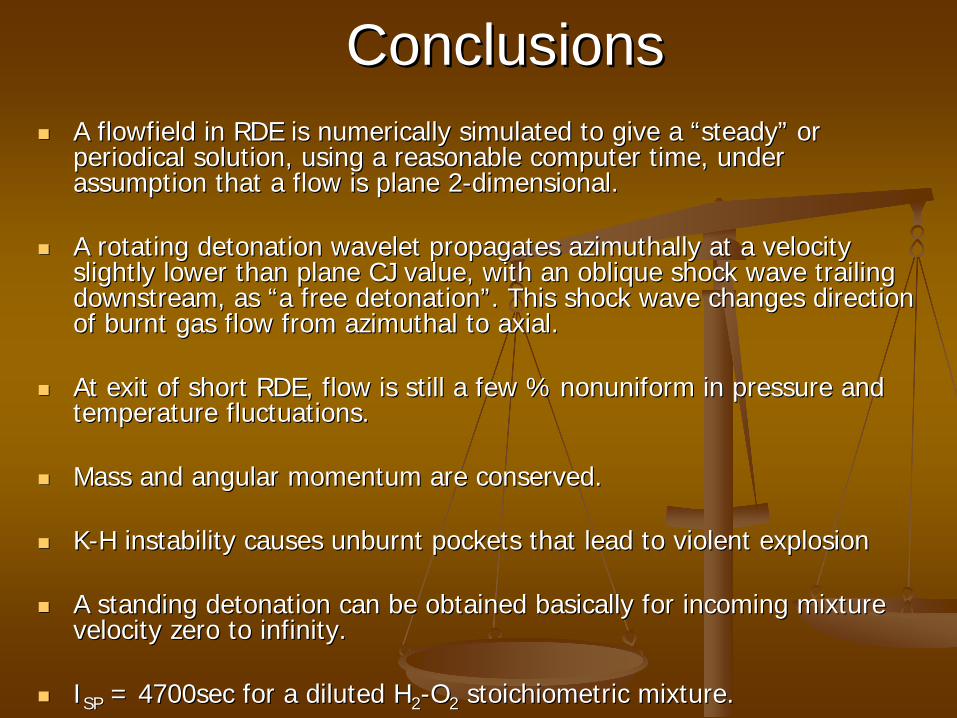
ConclusionsConclusions
A A flowfieldflowfield in RDE is numerically simulated to give a in RDE is numerically simulated to give a ““steadysteady”” or or periodical solution, using a reasonable computer time, under periodical solution, using a reasonable computer time, under assumption that a flow is plane 2assumption that a flow is plane 2--dimensional.dimensional.
A rotating detonation wavelet propagates azimuthally at a velociA rotating detonation wavelet propagates azimuthally at a velocity ty slightly lower than plane CJ value, with an oblique shock wave tslightly lower than plane CJ value, with an oblique shock wave trailing railing downstream, as downstream, as ““a free detonationa free detonation””. This shock wave changes direction . This shock wave changes direction of burnt gas flow from of burnt gas flow from azimuthalazimuthal to axial.to axial.
At exit of short RDE, flow is still a few % At exit of short RDE, flow is still a few % nonuniformnonuniform in pressure and in pressure and temperature fluctuations.temperature fluctuations.
Mass and angular momentum are conserved.Mass and angular momentum are conserved.
KK--H instability causes H instability causes unburntunburnt pockets that lead to violent explosionpockets that lead to violent explosion
A standing detonation can be obtained basically for incoming mixA standing detonation can be obtained basically for incoming mixture ture velocity zero to infinity.velocity zero to infinity.
II SPSP = 4700sec for a diluted H= 4700sec for a diluted H 22 --OO 22 stoichiometricstoichiometric mixture.mixture.