fundamentals of light-cell–polymer interactions inphoto
TRANSCRIPT

APL Bioeng. 4, 041502 (2020); https://doi.org/10.1063/5.0022693 4, 041502
© 2020 Author(s).
Fundamentals of light-cell–polymerinteractions in photo-cross-linking basedbioprinting Cite as: APL Bioeng. 4, 041502 (2020); https://doi.org/10.1063/5.0022693Submitted: 23 July 2020 . Accepted: 21 September 2020 . Published Online: 12 October 2020
Daniel Nieto , Juan Antonio Marchal Corrales , Alberto Jorge de Mora , and Lorenzo Moroni
COLLECTIONS
Paper published as part of the special topic on Biophysics of Biofabrication
This paper was selected as Featured
This paper was selected as Scilight
ARTICLES YOU MAY BE INTERESTED IN
Illuminating interactions in light-based bioprintingScilight 2020, 421101 (2020); https://doi.org/10.1063/10.0002283
Functional hydrogel bioink, a key challenge of 3D cellular bioprintingAPL Bioengineering 4, 030401 (2020); https://doi.org/10.1063/5.0018548
Time dependent stress relaxation and recovery in mechanically strained 3D microtissuesAPL Bioengineering 4, 036107 (2020); https://doi.org/10.1063/5.0002898
Fundamentals of light-cell–polymer interactionsin photo-cross-linking based bioprinting
Cite as: APL Bioeng. 4, 041502 (2020); doi: 10.1063/5.0022693Submitted: 23 July 2020 . Accepted: 21 September 2020 .Published Online: 12 October 2020
Daniel Nieto,1,2,3,a) Juan Antonio Marchal Corrales,3,4,5 Alberto Jorge de Mora,6 and Lorenzo Moroni2
AFFILIATIONS1Photonics4Life Research Group, Department of Applied Physics, Faculty of Physics, University of Santiago de Compostela,Santiago de Compostela 15782, Spain
2Complex Tissue Regeneration Department, MERLN Institute for Technology Inspired Regenerative Medicine,Universiteitssingel 40, 6229ER Maastricht, The Netherlands
3Department of Human Anatomy and Embryology, Institute of Biopathology and Regenerative Medicine,University of Granada, Granada 18016, Spain
4Instituto de Investigaci�on Biosanitaria de Granada (ibs.GRANADA), Granada 18012, Spain5Excellence Research Unit “Modeling Nature” (MNat), University of Granada, Granada 18016, Spain6SERGAS (Galician Health Service) and IDIS (Health Research Institute of Santiago de Compostela (IDIS),Orthopaedic Department, Universidad de Santiago de Compostela, Santiago de Compostela 15782, Spain
Note: This paper is part of the special issue on Biophysics of Biofabrication.a)Author to whom correspondence should be addressed: [email protected]
ABSTRACT
Biofabrication technologies that use light for polymerization of biomaterials have made significant progress in the quality, resolution, andgeneration of precise complex tissue structures. In recent years, the evolution of these technologies has been growing along with the developmentof new photocurable resins and photoinitiators that are biocompatible and biodegradable with bioactive properties. Such evolution has allowed theprogress of a large number of tissue engineering applications. Flexibility in the design, scale, and resolution and wide applicability of technologiesare strongly dependent on the understanding of the biophysics involved in the biofabrication process. In particular, understanding cell–lightinteractions is crucial when bioprinting using cell-laden biomaterials. Here, we summarize some theoretical mechanisms, which condition cellresponse during bioprinting using light based technologies. We take a brief look at the light–biomaterial interaction for a better understanding ofhow linear effects (refraction, reflection, absorption, emission, and scattering) and nonlinear effects (two-photon absorption) influence the biofabri-cated tissue structures and identify the different parameters essential for maintaining cell viability during and after bioprinting.
VC 2020 Author(s). All article content, except where otherwise noted, is licensed under a Creative Commons Attribution (CC BY) license (http://creativecommons.org/licenses/by/4.0/). https://doi.org/10.1063/5.0022693
I. INTRODUCTION
Bioprinting is a fast emerging technique, which makes biofabri-cating artificial tissues and the microscale deposition of living cells pos-sible.1,2 The ultimate objective of bioprinting is to create 3D artificialtissues that mimic the natural biological microenvironments, wherecells can function as well as they would in real tissues. The structuralgeometry and morphology of artificial structures should be controlledusing bioprinting tools to maintain high functionality at variousdimension scales to mimic the tissue complexity.3,4
Light-based biofabrication methods have been developed andused to generate biological scaffolds and complex tissue structures.5,6
The optical nature of light (noncontact, optically selective, and precise
processing) positions these technologies at the forefront of biofabrica-tion techniques with the ability for high precision biofabrication atsubmicrometer resolution (<1lm).
Most light based printers can be divided by the light source usedfor polymerization (using one photon or two photons), which is thenprojected over a bath filled with liquid photo to cross-linkable biomate-rials or cell-laden hydrogels onto a moving stage. Most common light-based technologies using photopolymerization include laser-basedSLA, mask-based SLA, and digital light projection (DLP) using digitalmirror devices (DMDs). These technologies are based on one photonpolymerization, initially using UV light7–10 and more recently visiblelight.11–13 On the other hand, multiphoton polymerization-based 3D
APL Bioeng. 4, 041502 (2020); doi: 10.1063/5.0022693 4, 041502-1
VC Author(s) 2020
APL Bioengineering REVIEW scitation.org/journal/apb

laser lithography14 is based on the absorption of two photons of nearinfrared light (NIR), to excite the same energy transition as ultraviolet(UV)one-photon absorption for cross-linking the biomaterial.
A. SLA
Conventional SLA was in fact the first technology introduced byCharles Hull in the 1980s for creating 3D constructs using UV light topolymerize materials.15 This was followed by other studies discussingthe kinetic modeling of linear, cross-linking photopolymerization andhighlighting the opportunities as industrially cured coatings and dentalfillings, and more generally three-dimensional rapid prototyping tech-niques.16,17 SLA bioprinting presents some advantages in comparisonwith other bioprinting techniques, such as extrusion and inkjet sys-tems. SLA bioprints photosensitive hydrogels in a layer by layer fash-ion rather than in struts or droplets. The bioprinting time for eachlayer is the same, but the total biofabrication time of the hole structuredepends on the thickness. This bioprinting characteristic of SLAreduces the biofabrication time of the hole tissue structure. Moreover,
SLA is a nozzle-free bioprinting technique, which avoids the inconve-nience associated with nozzle-based bioprinting technologies, resultingin cell-laden structures with viability higher than 90%.18,19
Commonly, SLA uses the light source that impinges into a bath filledwith a photosensitive biomaterial, which is placed onto a Z movingstage. The Z stage moves down to a predefined distance and the mate-rial is polymerized. This distance determines the vertical resolution ofthe SLA printer. More recently, a top-down approach was used, wherethe light source that was placed below the bath containing the bioma-terial, in this case, the Z platform, is moved up to a distance whichdetermines the thickness of the layer and hence Z resolution. Mask-based SLA uses a mask and a light source to project the photomask[Fig. 1(d)]. Laser-based SLA uses laser, which is focused using a lenswith XYZ movement to transfer the pattern. Bioprinting speeds usingSLA are higher than other conventional methods. Nevertheless, thismethod presented poor biocompatibility with low resolution.20
Although, initial studies have reported feature sixes of 150lm per sin-gle layer and with axial resolution�250lm,21,22 with the developmentof biomaterials and hydrogels, the biocompatibility and resolution of
FIG. 1. (a) A tumor angiogenesis model: (i) schematic showing the tumor angiogenesis model; (ii) schematic of the mask for printing; (iii) bioprinted microvasculature; and (iv)bioprinted tumor model. (b) A skeletal muscle model: (i) schematic showing the skeletal muscle tissue; (ii) schematic of the mask for printing; (iii) bioprinted skeletal tissuemodel; and (iv) PrestoBlue measurements of cell proliferation in the bioprinted structures. (c) A tendon-to-bone insertion model: (i) schematic of the tendon-to-bone insertionsite; (ii) schematic of the mask for printing; (iii) bright-field optical image showing a bioprinted dye-laden GelMA structure; and (iv) bioprinted tendon-to-bone model.Reproduced with permission from Miri et al., Adv. Mater. 30, 1800242 (2018). Copyright 2018 John Wiley and Sons. (d) Schematics of stereolithographic bioprinting process:(i) laser-based and (ii) mask-based. (e) Schematic of the DLP bioprinting process: (i) gray scale digital mask and (ii) images of fluorescently labeled hiPSC-derived hepatic pro-genitor cells (hiPSC-HPCs). Reproduced with permission from Ma et al., Proc. Natl. Acad. Sci. U. S. A. 113, 2206–2211 (2016). Copyright 2016 PNAS. (f) The cross section ofa TPP-bioprinted mouse paw bone imaged using scanning electron microscopy and the intricate contours within the structure that arose from the bioprinting process. (g)Schematic illustration of the experimental setup for two-photon bioprinting along with a zoomed description of focal plane and distribution of light intensity in the laser focus of aGaussian beam is shown. Images (f) and (g) were reproduced with permission Miri et al., Lab Chip 19, 2019–2037 (2019).50 Copyright 2019 Royal Society of Chemistry.
APL Bioengineering REVIEW scitation.org/journal/apb
APL Bioeng. 4, 041502 (2020); doi: 10.1063/5.0022693 4, 041502-2
VC Author(s) 2020

SLA improved to 50lm.18 SLAs have been commonly used inmanufacturing industries and more recently used for tissue engineer-ing applications. Initially, SLA has been used for bone tissue models.Catros et al. used an SLA bioprinter for patterning nanohydroxyapa-tite (nHA) and osteoblastic cells in 2D and adapted to the biofabrica-tion of 3D composite materials toward healing bone defects.23 Wangused an SLA bioprinting system in combination with visible photosen-sitive bioinks [poly(ethylene glycol) diacrylate (PEGDA), gelatin meth-acryloyl (GelMA), and eosin Y based photoinitiator], resulting in NIH3T3 cell bioprinting with 50lm resolution and high cell viability.24
B. Digital light projection
The printing speed of SLA can be significantly improved byusing mask-less DMD-based bioprinting. The DMD-based bio-printing uses an array of micromirrors (the dimension of eachmicromirror can be in the order of 5–10 lm) to selectivelyswitch the light intensity of each micromirror (each individualmirror can be controlled on two positions, being either 0-darkor 1-light reflecting and with speeds on the order of kilohertz)and project it over light-sensitive biopolymers that polymerizethe preselected light patterns transferred by the DMD in a layerby layer fashion [Fig. 1(e)]. DMD technology has arisen as analternative for high-throughput DLP printing, resulting in goodbiocompatibility for seeding cells.25 Zhu et al. used a DMD bio-printer for generating prevascularized tissue models with com-plex geometries (widths �50 lm and heights ffi50 lm) using abioink of endothelial cells, GelMA, and glycidal methacrylate–-hyaluronic acid.26 Miri et al. were able to generate biological tis-sue structures such as tumor angiogenesis [Fig. 1(a)], musclestrips [Fig. 1(b)], and musculoskeletal junctions [Fig. 1(c)] withprinting resolutions on the order of 10 lm by using a DMDbioprinter working at 365 nm, in combination with microflui-dics.8 Ma et al. have used DMD to fabricate hexagonal lobulestructures of GelMA (15% w/v) seeded with HUVECs (HumanUmbilical Vein Endothelial Cells) (with a resolution �50 lm)that where incorporated on a liver-on-a-chip.27 These studieshighlight the high speed of bioprinting associated with DMD(under 1 min), accuracy (10–50 lm), and versatility (from bio-compatible scaffolds to cell-laden structures with differentgeometries) of the mask-less methods.
C. Multiphoton polymerization-based 3D laserlithography
The challenge associated with 3D biofabrication using single-photon photopolymerization is to avoid the off-focal photopo-lymerization that may ultimately cure undesirable parts of thedesigned construct.28,29 Biofabrication using multiphotonpolymerization benefits from the high resolution inherent inthe two-photon polymerization (TPP) process, which can gen-erate 3D structures with micro/nanoscale resolution [Fig.1(f)].30 The nonlinear optical phenomenon associated withTPP occurs when irradiating using a focused femtosecondlaser beam at infrared wavelength, by simultaneous absorptionof multiple photons, which induces photopolymerization of asmall area (�100 nm), based on the radical generation due to
the interaction between the used photoinitiator and the femto-second laser beam. This interaction allows the generation of3D tissue structures with ultra-high-resolution (from lm tonm) that cannot be achieved by other conventional photolitho-graphic methods.31 Ovsianikov et al. used TPP to fabricate bio-degradable tissue scaffolds using gelatin modified with metha-crylamide (GelMod), which were seeding with adipose-derivedstem cells, presenting good adhesion and resulting in prolifera-tion and differentiation to adipocytes.32 Koroleva et al. demon-strated that hybrid Zr–Si porous scaffolds were fabricatedusing TPP promoted mesenchymal stem cells (hMSCs) to dif-ferentiate toward the osteogenic lineage.33 Commonly usedTPP systems include two X–Y galvanometric scanners to movethe laser focus in the X–Y coordinates and a high resolution Zstage that performs axial scanning [Fig. 1(g)]. Due to thecoherent properties of the laser beam with optimal focusingcapabilities, the TPP process can generate high-resolution 3Dfeatures. Nevertheless, the throughput is restricted by thesequential laser scanning process. This limitation is furtherenhanced when printing complex hollow structures or largevolume structures. Different optical solutions have been pro-posed, which include microlens arrays, spatial light modula-tors, and diffractive optical elements, most of them based onsplitting the laser into multiple foci. Geng et al. have used TPPin combination with a DMD scanner for generating tens oflaser foci that can be controlled individually by achievingdiffraction-limited resolution (500 nm–1600 nm) and a proc-essing speed of 22.7 kHz.34 These studies highlighted theopportunities of TPP associated with high resolution features.Nevertheless, several key challenges still remain, which includethe failure of biofabricating cell-laden constructs with clinicallyrelevant dimensions. TPP systems that are commercially avail-able are very expensive and are difficult to adapt to the particu-lar application. The dearth of biomaterials (biocompatible andbiodegradables) for TPP is another inconvenience for coveringdifferent biological applications. The dearth of water solublePIs limits the uses of photopolymers with high water contents.Although TPP is very precise, it is a relatively slow process,which results in small scaffolds of structures difficult to handlein tissue engineering. Biological experiments need statisticalexperiments with a huge amount of identical structures. In thissense, efforts need to be taken to develop novel photopolymersand photoinitiators for TPP aimed at increasing the fabricationspeed and reducing cytotoxic effects.
Table I shows the characteristics of the most common light basedtechnologies using photopolymerization.
D. Basic light interaction process during bioprinting
During photolithographic biofabrication, the primary light inter-actions can be caused mainly by linear phenomena of refraction,reflection, absorption, emission, and scattering and nonlinear effectsas in the case of multiphoton polymerization.35 Reflection occurswhen light reflects on the surface of the biomaterial without penetrat-ing it. Refraction occurs as a consequence of the change in the propa-gation angle of light when it passes from air to the biomaterial duringbioprinting. Absorption and dispersion that occur both in a biological
APL Bioengineering REVIEW scitation.org/journal/apb
APL Bioeng. 4, 041502 (2020); doi: 10.1063/5.0022693 4, 041502-3
VC Author(s) 2020

biomaterial and in cells are dependent on the wavelength of light,which is complete through intracellular and extracellular constituents.Emission is a phenomenon that consists of an energy transmission tothe atoms of the biological component, in which their electrons arepromoted to higher levels of energy. While the energy of photons usedto irradiate cells has a dramatic impact on phototoxicity, it can beexpected that the bioprinting limitations are mostly related to the pho-ton energy and the wavelength of the light source used to photo-cross-link the biomaterials. Although cells exhibit a very distinct irradiationsensitivity, the phototoxicity increases dramatically with decreasing
irradiation wavelength.36 Infrared light, as long as we do not pass thecellular thermal threshold through which apoptosis and destructionare induced, is safe. Nevertheless, ultraviolet light is mostly used forlight-curing photopolymerization on stereolithographic bioprintingand has been reported to damage the DNA of cells.37,38
Following light absorption, in certain circumstances, cells canundergo a wide variety of photochemical and photophysical processes,which include fluorescence, thermal effects, photoablation effects,plasma-induced ablation, and photodisruption.39 These effects mustbe avoided during bioprinting. Photoablation occurs due to the action
TABLE I. Most common light based bioprinting technologies using photopolymerization.
Bioprintingtechnology Advantages Common advantages Disadvantages
Commondisadvantages References
Digital lightprojection(DMD)
High cell viability
Direct incorporation ofcells during bioprinting
Dynamic bioprinting
High resolution
Noncontact biofabricationsystems (No shear,
mechanical and thermalstress, nor clogging during
bioprinting)
High resolution anddensity; additive
operation
Photopolymerization is cellfriendly (pH, temperature)
Customized systems/required skills
Moderate cost for high res-olution systems
UV light can damagemicromirrors
Require photocurablebioink (limited bioma-
terials)
Monomer toxicity(biomaterial reactionsduring bioprinting)
Custom made equip-ment (require technical
staff)
8927
Laser-basedSLA
High resolution(1� 50 lm)
Bioprinting of highviscosity
Selective exposure ofbioinks
Medium speed
Limited scalability
Laser source might have anadverse effect on the cellu-
lar genetic material
Moderate cost for high res-olution systems
61227
Mask-basedSLA
High cell viability
Easy control of matrixproperties
Low cost technology
Fast speed
Monomer toxicity and useof ultraviolet radiation
Require a mask pattern
Multiple step processes
32527
Multiphotonbioprinting
Ultra-high resolution(nm to few micrometers)
High penetration depth
No UV light required
High water content bioinks
Limited by the speed ofprinting for high-
throughput screening
High cost technology
Require optimization ofphotocurable bioink
11242527
APL Bioengineering REVIEW scitation.org/journal/apb
APL Bioeng. 4, 041502 (2020); doi: 10.1063/5.0022693 4, 041502-4
VC Author(s) 2020

of an intense ultraviolet (UV) laser pulse that photochemically decom-poses various cellular and extracellular components. Plasma-inducedablation and photodisruption occur as a consequence of exposing thebiological material to a power density above 1011W/cm2.40
Fluorescence originates from the transition from an excited singletstate to a ground state vibrational mode. Thermal effects are the resultof the conversion of absorbed light energy into heat. The above-mentioned mechanisms need to be considered carefully to increasecell viability. Light power, selected wavelengths, and exposure time areperhaps the main determinants that dominate the process during lightbased biofabrication. It is essential to adapt the light beam and opti-mize the light parameter to minimize cell damage without losing itsability to light cure or achieve cross-linking in the medium. MostStereolithography (SLA) printers can be divided by the light sourceused for polymerization (using one photon or two photons), which isthen projected over a bath filled with liquid photo to cross-linkablebiomaterials or cell-laden hydrogels onto a moving stage. Althoughphoto-cross-linking is typically associated with SLA bioprinting,other biofabrication technologies, such as extrusion, may use photo-cross-linking as a secondary process. Bram et al. have used extrusionbioprinting based on a two-step cross-linking approach. Secondaryphoto-cross-linking was applied for shape maintenance. This two-stepcross-linking methodology can be used with a broad window of extrusionbiofabrication parameters that allow printing at a low viscosity (4mPas)to maintain high cell viability (>80%) and with good shape fidelity. Thiseliminates the problems associated with low viscosity bioinks (complexchemical modifications, multiple initiation systems, and viscosityenhancers).59 There is a vast amount of reviews covering the advantageand disadvantages of different bioprinting technologies and more recently
the fundamentals and practical aspects of light based bioprinting,41,42 butfew of them covering the primary cell–light interactions.
In this article, we consider the impact and behavior of light dur-ing bioprinting, focusing on high resolution structures with high cellviability. Section II is related to polymer–light interactions centered onhigh resolution structures. Section III is devoted to biophysical princi-ples at that cell–light interaction level and parameters involved tomaintain high cell viability, and Sec. IV presents a future outlook andconclusions.
II. POLYMER–LIGHT INTERACTIONS
Photopolymerization comprises the reaction of monomers thatform large networks when irradiated with light (by the single-photonor two-photon absorption). This absorption can be promoted by thereactant monomer or by the transfer of energy absorbed by a photoini-tiator.43 Photoinitiators used for photopolymerization generate freeradicals when they are exposed to light and react with monomers and/or oligomers for initiating polymer chain reactions and growth.
A. Photopolymerization mechanism (single-photon vstwo-photon)
During photopolymerization, the photon interactions at the ini-tial step differ from the ordinary thermal polymerization, but the fol-lowing steps being propagation, termination, and chain transferremain the same. Under such premises, the photopolymerization bio-printing process can be classified into two categories: single-photonphotopolymerization and multiphoton photopolymerization (Fig. 2).
In single-photon SLA, the polymerization process is originatedvia linear single-photon absorption [Fig. 3(a)].44 The energy of the
FIG. 2. Diagram of stereolithographic processes based on the exciton radiation form and energy (single photon and multi-photon).
APL Bioengineering REVIEW scitation.org/journal/apb
APL Bioeng. 4, 041502 (2020); doi: 10.1063/5.0022693 4, 041502-5
VC Author(s) 2020

photon, Ep, is equivalent or superior than the material bandgap Eg.With Ep ¼ hv ¼ hc=k being the governing law of this process, itmeans that high energy photons and short wavelengths are required.In most cases, UV wavelengths shorter than 365nm are selected. Onephoton absorption with Ep>Eg motivates the electron to move fromthe valence band to the conduction band. This process alters thechemical bond inducing polymerization process, which is responsiblefor biomaterial cross-linking. Noncoherent light sources at low powerlevels can also induce linear absorption. Nevertheless, as the lightintensity increases, typically using coherence laser sources, nonlinearabsorption can take place. The UV (kUV) photosensible biomaterialcan be also photopolymerized by infrared (IR) wavelengths of nearlydouble wavelength (kIR¼ 2kUV).
45 TPP is based on this mechanismand comprises the absorption of two photons simultaneously througha virtual state for molecule excitation [Fig. 3(a)]. The virtual levels(�fs) have a particularly short lifetime, which results in the instanta-neous absorption of almost two photons. This excitation processdepends quadratically on the incident light intensity46 and the TPPrequires high light intensities (>GW/cm2). The TPP process can bedescribed as follows:47 a molecule in a ground energy state Gs isexcited to an excited state Es. In this process, the molecules absorb twosingle photons (Gs and Es are separated with an energy difference ofEf above the Gs) as shown in Fig. 3(a). A virtual state Vs is created bythe absorption of the two photons [both photons having the same
energy levels¼E1 (degenerate, Ef¼ 2E1)]. With further excitation,they lose energy and move to another state R, where vibrational relaxa-tion is induced by the lowest vibrational level of the lowest-energy Es[Fig. 3(a), dashed arrow], and then return to the ground state by apathway that can be radiative or nonradiative.
The TPP process is originated precisely at the focal volume of thelaser beam [Fig. 3(b)], which facilitates the generation of precise andhigh-resolution 3D structures. The biggest limiting factor in the exten-sive use of TPP for biological applications is the slow manufacturingtime that accompanies high-resolution structuring which can compro-mise cell viability. This can be overcome by using optical systems tomodulate the behavior of light. Gittard et al. have demonstrated TPPusing a multiple spotlight approach by generating microstructurearrays for tissue engineering. Computer-generated hologram patternswere used to generate multiple spotlights from one laser beam, signifi-cantly reducing the manufacturing time. These multiple foci were usedto simultaneously produce multiple tissue scaffolds by TPP.48 Atryet al. demonstrated the applicability of diffractive optical elements forfabricating large scaffolds at rates several times faster than by singlespotlight.49
The two key properties that conditioned the resolution oflaser direct write bioprinting, mask based SLA, and DMD-basedbioprinting processes, which are mainly determined by the thick-ness of the photosensitive resin, are the directionality of the
FIG. 3. (a) Single-photon and two-photon absorption processes, (b) Gaussian beam profile of a laser beam, and (c) single-photon and two photon absorption features on thebiomaterial.
APL Bioengineering REVIEW scitation.org/journal/apb
APL Bioeng. 4, 041502 (2020); doi: 10.1063/5.0022693 4, 041502-6
VC Author(s) 2020

impinging light and the lower scattering of light (perpendicular tothe laser). The thickness (z resolution) can be controlled by adjust-ing the laser characteristics (pulse width, light wavelength, power,repetition rate, and size of the beam) and the properties of the resin(including viscosity and superficial stress).50 According to thepolymerization kinetics of the photo-cross-linking mechanisms,we can assume the following relationship to define the thickness ofthe light-cured material:
Cd ¼ DplnEiEc
� �;
where Cd is the depth of curing (lm), Dp is the depth of penetration(lm), Ei is the irradiation of light (mJ/cm2), and Ec is the thresholdvalue of energy of the gelation point for the liquid resin (mJ/cm2). AsEi approaches Ec, the layer is cured, and the resin is solidified. Becauseof the nonlinear nature of two photon polymerization and the thresh-old behavior, high-quality and high-resolution features can beobtained. By adjusting different laser parameters (pulse energy andpulse repetition rate), the printing resolution (<100nm) can beincreased by overcoming the diffraction limit.
The two-photon absorption mechanism happens in a resinthat initially does not absorb the selected wavelength of the laserlight, allowing its penetration in the material [Fig. 3(c)]. The bio-printing resolution of TPP is related to the incident laser light andthe square of its intensity. A high magnification focal lens focuseslaser energy at a small focal point where the highest amount ofabsorption takes place. Assuming a Gaussian laser beam profilewith an intensity distribution I(r, z) at distances (z in the directionof propagation and r along the cross section) from the center canbe defined as
I r; zð Þ ¼ I0w20
w zð Þ2
" #e�2r2w zð Þ2 ;
where I0, x0, and x(z) are the intensity at the center of the Gaussianbeam (r¼ 0, z¼ 0), the waist of the beam, and the radius of the beamin the plane with a distance of z, respectively. The average intensity atthe focus plane can be defined as
Ifocus ¼w
pw02 1 fht
;
where W is the power average, 1 is the width of the selected pulse, f isthe repetition rate, h is the Planck constant, and t is the frequency oflight. The photon-polymerization is initiated when the density of radi-cals P (r, z) surpasses the threshold Pth [P (r, z) � Pth]. The intensityat the focal plane (z¼ 0) reaches the threshold, where
I r; zð Þ ¼ I r; 0ð Þ ¼ I0 exp�2r2w0
2
� �:
All the aforementioned interactions and effects have influenceover the bioprinting process.
B. Photoinitiators
The polymerization efficiency of the developed bioinks dependsstrongly on the selection of the photoinitiator. The photoinitiatorshould be efficient in free radical generation with low toxicity. For
engineering of living tissues, photoinitiators sensitive to UV are themost used. Photoinitiators can be separated into two categories (inrelationship with the radical generation mechanisms): (1) Type-Iphotoinitiators (cleavable photoinitiators) and (2) Type-II (bimolecu-lar photoinitiating). During bioprinting, for initiating polymerization,Type-I photoinitiators generate two radicals. The starting process ofType-II (e.g., benzophenone/tertiary amine) presents more complex-ity. For example, benzophenone is excited and promotes fast electrontransfer (from the lone pair of tertiary amine), which is followed bythe proton transfer process; this process provides the radical (H-donor) that initiates photopolymerization. To avoid the UV light dam-aging effects, including DNA damage and cancer effects,51 some visiblelight photoinitiators have been investigated and demonstrated to beuseful for bioprinting with cells. LAP (lithium phenyl-2,4,6-trimethyl-benzoylphosphinate) is a UV photosensible photoinitiator, which hasalso been demonstrated to be sensitive to blue light (near UV).52 EosinY (20,40,50,70-tetrabromofluorescein disodium salt) is sensitive around514 nm. Hydrogels developed for working with Eosin Y maintain cellfunction and present less toxicity than Irgacure 2959 (1-[4-(2-hydrox-yethoxy)-phenyl]-2-hydroxy-2-methyl-1-propanone).53–55 Naturalphotoinitiators such as Riboflavin (FR) and Vitamin B2, were demon-strated to induce photo-cross-linking on alginate hydrogels56 and wereused as visible light photoinitiators in the thiol–ene polymerization ofpolyethylene glycol (PEG)-based hydrogels.57 A photoinitiator basedon a ruthenium complex [tris-bipyridyl-ruthenium (II) hexahydrate]and sodium persulfate (SPS) was used to initiate visible light cross-linking of hyaluronic acid/gelatin-based bioinks.58 Soliman et al. haveused ruthenium (Ru) and sodium persulfate (SPS) cross-linkers incombination with allyl-functionalized gelatin (Gel-AGE) bioink forextrusion bioprinting based on the dual-step cross-linking approach,where a primary (partial) cross-linking in the absence of light is per-formed to alter the bioink’s rheological properties with subsequent sec-ondary post-printing cross-linking for shape maintenance.59 Lim et al.have used a Vis þ Ru/SPS system, demonstrating better cell cytocom-patibility than the commonly used UV þ I2959 system. Encapsulatedcells remained >85% viable even when using high Ru/SPS concentra-tions, visible-light intensities, and longtime exposure times (21 days),which highlight the potential Vis þ Ru/SPS system to avoid the celldamage associated with UV light and for maintaining high cell viabil-ity, shape fidelity, and metabolic activity.60 More recently, poly-a-ketoester based photoinitiators have demonstrated good cell viabilityin combination with methacrylates and polyethylene glycol (PEG)diacrylate-based hydrogels.61 It appears, therefore, clear that visiblelight sensible materials are emerging as optimal PI for cell-laden bio-inks for bioprinting. A list of the commonly used PIs and their lightabsorbing peaks are showed in Table II.
III. CELL–LIGHT INTERACTIONS
Human cells vary in size in a range from 5 lm of erythrocytes(red blood cells), 20 lm of leukocytes, to tens of centimeters of neuro-nal axons.62 They can therefore be either larger or smaller than thelight wavelength used for bioprinting. The interaction of cells and cell-laden biomaterials with light can be caused mainly by linear phenom-ena of refraction, reflection, absorption, emission, and scattering.63
During bioprinting, the light refracts when it travels from thelight source (by air at a particular angle) and reaches a substance (bio-material) which presents another refractive index. The refractive index
APL Bioengineering REVIEW scitation.org/journal/apb
APL Bioeng. 4, 041502 (2020); doi: 10.1063/5.0022693 4, 041502-7
VC Author(s) 2020

determines the phase and speed of light propagation. Reflection occurswhen light reflects on the surface of the biomaterial without penetrat-ing in it, due to the difference between the refractive index of air andbiomaterial. Reflection at the microscopic level will depend on the cellsurface morphology and because of it will not be uniform. Lightabsorption is complete through intracellular and extracellular constitu-ents and occurs as a consequence of the transition from a grown state(low energy state) to an excited state (high energy state) of amolecule.64,65
Emission is a phenomenon that consists of energy transmissionto the atoms of the biological component, in which their electrons arepromoted to higher levels of energy, in some circumstances unstable,leaving holes under them. When electrons return to these holes withless energy, the excess of energy is returned as light, with differentcharacteristics from the incident ray. Scattering occurs due to loss ofdirectionality of light and spread of the light beam spot. This phenom-enon is what regulates the light intensity distribution in the cell-ladenbiomaterials.
Light scattering in tissues is dominated by Mie scattering. Thistype of scattering occurs when particles are the same size as the wave-length of light (when particles are much smaller than the wavelength,Rayleigh scattering predominates). Cells, nuclei, and organelles all fallinto this classification. In addition, the lipid membranes that enclosethese structures have a different refractive index than the surroundingmedium (around 1.5). The dispersion of light into the tissue is moti-vated by the differences of the refractive index. When the differencebetween the medium and the cells increases, the dispersion alsoincreases. The relationship with the wavelength can be complex, but ingeneral, the longer the wavelength, the lower the scattering, whichindeed is one of the benefits of TPP.66
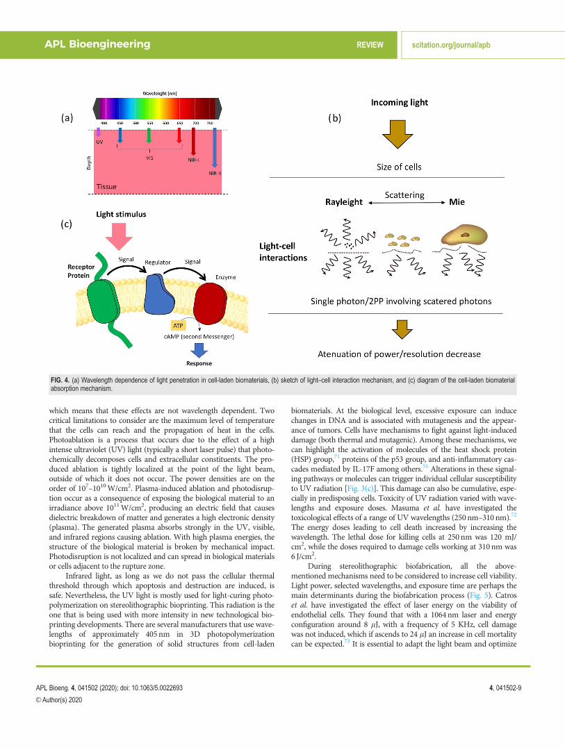
In Rayleigh scattering, subcellular components such as organellescan be a scattering component. This type of scattering depends mostlyon the following parameters: the dimensions of the scattering com-pounds (cells or organelles in bioprinting), scattering centers and thesurrounding medium refractive index variations, and the light wave-length [see Fig. 4(b)].67 We can consider that Rayleigh scattering isinversely proportional to the square of the wavelength of light. Thatmeans that a short wavelength (UV) will be more scattered than along wavelength (IR). By taking scattering individually as a mechanismfor optical loss during bioprinting, we can assume that the longer thewavelength is, the deeper will the light penetrate into a cell laden bio-material sample [Fig. 4(a)].
Absorption is controlled by Beer’s law, especially when workingwith monochromatic beams.68 It establishes empirically an absorption
coefficient in the matter, and corelates this absorption to the wave-length of the incident light. In studies mainly on human skin tissues,due to a high interest in being an area permanently exposed to radia-tion, an increase in absorption and less penetration of light withshorter wavelengths (in studies with wavelengths from 300 to 800 nm)has been demonstrated.69 This law is valid in liquid media such as cel-lular and intracellular interstitial fluids, and establishes an increase inabsorption with the concentration of solute in the medium in cell-laden biomaterials. Let us consider a sample which is in a solution,contained in a box which is transparent to the radiation of interest(monochromatic) and with uniform thickness. With I0 being theintensity of the radiation that enters the sample and I being the inten-sity of the radiation that goes across the sample, the transmittance T isgiven by T¼ I/I0. Beer’s law can be expressed as
log10II0
� �¼ abc;
where b is the thickness of the box, c is the concentration of the samplein the solution, and a is the capacity of the sample to absorb radiation.Beer’s law can be simplified as A¼ abc, with A being the absorbance,and is expressed as
A ¼ log10II0
� �:
Beer’s law says that the concentration and the absorbance are linearly pro-portional (when the cell thickness and the radiation wavelength remainconstant). Therefore, both the absorption and the dispersion that occurboth in a biological biomaterial and in cells are conditioned by the wave-length and increased in the blue region of the electromagnetic spectrumcompared to the red and infrared regions.69 Following light absorption,cells undergo a wide variety of photochemical and photophysical pro-cesses. Some cellular elements generate fluorescence (emissivity) as theyare excited directly or when they get energy from another cellular element.This is defined as autofluorescence and the constituent it emits is calledfluorochrome. Fluorescence, which has a half-life between 1 and 10 ns,originates from the energy transition (excited singlet state to a groundstate vibrational mode).70 Other processes that can be observed in light–biological matter interactions, apart from the autofluorescence discussedabove and photochemical processes, are thermal effects, photoablationeffects, photodisruption, and plasma-induced ablation.40
Thermal effects can be considered as the result of the conversionof absorbed light energy into heat. They can be produced by pulsedand continuous wave (CW) lamps and lasers. They are nonspecific,
TABLE II. Common PIs used in light-based bioprinting.
Name (chemical) Abbreviation Absorbing peak (nm) Sources
20,40,50,70-Tetrabromofluorescein disodium salt Eosin Y 514 54, 552,20-Azobis[2-methyl-n-(2-hydroxyethyl)propionamide] VA-086 385 53Lithium phenyl-2,4,6-trimethylbenzoylphosphinate LAP 375 521-[4–(2-Hydroxyethoxy)-phenyl]-2-hydroxy-2-methyl-1-propanone Irgacure 2959 257 8Riboflavin (Vitamin B2) RF 220–240 56, 57Ruthenium with a reagent (sodium persulfate) Ru (SPS) 400–450 58–60Poly-a-ketoester based photoinitiators Poly-a-ketoesters 330 61
APL Bioengineering REVIEW scitation.org/journal/apb
APL Bioeng. 4, 041502 (2020); doi: 10.1063/5.0022693 4, 041502-8
VC Author(s) 2020
which means that these effects are not wavelength dependent. Twocritical limitations to consider are the maximum level of temperaturethat the cells can reach and the propagation of heat in the cells.Photoablation is a process that occurs due to the effect of a highintense ultraviolet (UV) light (typically a short laser pulse) that photo-chemically decomposes cells and extracellular constituents. The pro-duced ablation is tightly localized at the point of the light beam,outside of which it does not occur. The power densities are on theorder of 107–1010W/cm2. Plasma-induced ablation and photodisrup-tion occur as a consequence of exposing the biological material to anirradiance above 1011W/cm2, producing an electric field that causesdielectric breakdown of matter and generates a high electronic density(plasma). The generated plasma absorbs strongly in the UV, visible,and infrared regions causing ablation. With high plasma energies, thestructure of the biological material is broken by mechanical impact.Photodisruption is not localized and can spread in biological materialsor cells adjacent to the rupture zone.
Infrared light, as long as we do not pass the cellular thermalthreshold through which apoptosis and destruction are induced, issafe. Nevertheless, the UV light is mostly used for light-curing photo-polymerization on stereolithographic bioprinting. This radiation is theone that is being used with more intensity in new technological bio-printing developments. There are several manufacturers that use wave-lengths of approximately 405nm in 3D photopolymerizationbioprinting for the generation of solid structures from cell-laden
biomaterials. At the biological level, excessive exposure can inducechanges in DNA and is associated with mutagenesis and the appear-ance of tumors. Cells have mechanisms to fight against light-induceddamage (both thermal and mutagenic). Among these mechanisms, wecan highlight the activation of molecules of the heat shock protein(HSP) group,71 proteins of the p53 group, and anti-inflammatory cas-cades mediated by IL-17F among others.51 Alterations in these signal-ing pathways or molecules can trigger individual cellular susceptibilityto UV radiation [Fig. 3(c)]. This damage can also be cumulative, espe-cially in predisposing cells. Toxicity of UV radiation varied with wave-lengths and exposure doses. Masuma et al. have investigated thetoxicological effects of a range of UV wavelengths (250nm–310 nm).72
The energy doses leading to cell death increased by increasing thewavelength. The lethal dose for killing cells at 250 nm was 120 mJ/cm2, while the doses required to damage cells working at 310nm was6 J/cm2.
During stereolithographic biofabrication, all the above-mentioned mechanisms need to be considered to increase cell viability.Light power, selected wavelengths, and exposure time are perhaps themain determinants during the biofabrication process (Fig. 5). Catroset al. have investigated the effect of laser energy on the viability ofendothelial cells. They found that with a 1064nm laser and energyconfiguration around 8 lJ, with a frequency of 5 KHz, cell damagewas not induced, which if ascends to 24 lJ an increase in cell mortalitycan be expected.73 It is essential to adapt the light beam and optimize
FIG. 4. (a) Wavelength dependence of light penetration in cell-laden biomaterials, (b) sketch of light–cell interaction mechanism, and (c) diagram of the cell-laden biomaterialabsorption mechanism.
APL Bioengineering REVIEW scitation.org/journal/apb
APL Bioeng. 4, 041502 (2020); doi: 10.1063/5.0022693 4, 041502-9
VC Author(s) 2020
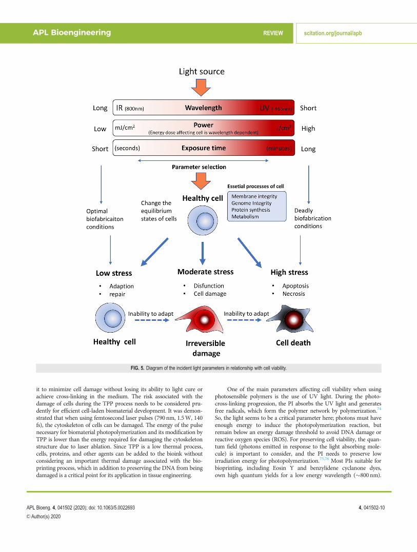
it to minimize cell damage without losing its ability to light cure orachieve cross-linking in the medium. The risk associated with thedamage of cells during the TPP process needs to be considered pru-dently for efficient cell-laden biomaterial development. It was demon-strated that when using femtosecond laser pulses (790 nm, 1.5W, 140fs), the cytoskeleton of cells can be damaged. The energy of the pulsenecessary for biomaterial photopolymerization and its modification byTPP is lower than the energy required for damaging the cytoskeletonstructure due to laser ablation. Since TPP is a low thermal process,cells, proteins, and other agents can be added to the bioink withoutconsidering an important thermal damage associated with the bio-printing process, which in addition to preserving the DNA from beingdamaged is a critical point for its application in tissue engineering.
One of the main parameters affecting cell viability when usingphotosensible polymers is the use of UV light. During the photo-cross-linking progression, the PI absorbs the UV light and generatesfree radicals, which form the polymer network by polymerization.74
So, the light seems to be a critical parameter here; photons must haveenough energy to induce the photopolymerization reaction, butremain below an energy damage threshold to avoid DNA damage orreactive oxygen species (ROS). For preserving cell viability, the quan-tum field (photons emitted in response to the light absorbing mole-cule) is important to consider, and the PI needs to preserve lowirradiation energy for photopolymerization.75,76 Most PIs suitable forbioprinting, including Eosin Y and benzylidene cyclanone dyes,own high quantum yields for a low energy wavelength (�800nm).
FIG. 5. Diagram of the incident light parameters in relationship with cell viability.
APL Bioengineering REVIEW scitation.org/journal/apb
APL Bioeng. 4, 041502 (2020); doi: 10.1063/5.0022693 4, 041502-10
VC Author(s) 2020

Salt-based PIs (LAP and Irgacure 2959) own high quantum yieldswith conversion kinetics very fast for a high energy wavelength(�400nm).77 Thus, cytocompatibility wavelength ranges usually arein the range of near-UV light (k¼ 300–400nm). In fact, using severalphotoinitiators has been proved to maintain high cell viability workingat low concentrations with short UV exposure time and low intensityresulting in good cell viability. Miri et al. have used LAP in combina-tion with poly(ethylene glycol) diacrylate (PEGDA) and gelatin metha-cryloyl (GelMA) at LAP concentrations of (1.0% w/v) and (0.03% w/v),respectively. Using a DMD bioprinter working at 365nm, in combina-tion with microfluidics, they were able to generate biological tissuesstructures such as tumor angiogenesis, muscle strips, and musculoskel-etal junctions.8 However, large UV exposure times are usually requiredduring 3D bioprinting of thick structures, which can diminish the cellviability or promote DNA damage of cells.78 Then, using the highestcytocompatible light intensity and optimizing the concentration of PIsfor an efficient and fast cross-linking process in combination with ashort light exposure time allow reducing prolonged cell exposure tofree radicals.79
Recently, Ruskowitz and DeForest have demonstrated that therate of proliferation remains the same and no cell death was observedwhen irradiating fibroblasts and human mesenchymal stem cells(NIH3T3) with a variety of light intensities (1, 5, 10, and 20 mWcm�2) at 365 nm. Nevertheless, they found that cells increase apoptosisby caspase activation in response to UV induced oxidative stressresulting from a UV light exposure (k¼ 254nm, 30 s at 300lWcm�2). A deeper analysis revealed that using a UV light of 365 nmdoes not alter the proteome nor shift protein production. Meanwhile,as an effect of induced DNA damage, 24 h after the light exposure at254 nmwavelength, 40 proteins were differentially expressed includingthe down-regulation of several histones and the up-regulation of thecellular tumor protein p53. These results showed that light-inducedcell death is wavelength-dependent, which emphasize that for 3D bio-fabrication, using photoresponsive biomaterials is a key factor toappropriately select light treatments.80
Bioprinting using living cells was demonstrated with primarycells, adult stem cells, and immortalized cell lines, with a variety of bio-printing technologies and biomaterials;81 and more recently withinduced Pluripotent stem cells (iPSCs).82 Among these cell sources,iPSCs represent a huge potential in bioprinting for regenerative medi-cine, modeling diseases, and toxicological studies. Since the recent dis-covery of iPSCs and due to their unlimited self-renewal andpluripotent differentiation capabilities, they have been used for investi-gating disparate biological mechanisms.83 The indefinite division andpluripotency properties of iPSCs result in an unlimited source of anyadult healthy and diseased cell type. However, iPSCs are more sensitiveto handling procedures, which can influence pluripotency and differ-entiation. In this sense, although iPSCs are UV sensitive, the nature ofthe light based bioprinting process (noncontact process) represents themain advantage. Koch et al. have investigated laser bioprinting ofundifferentiated human iPSCs in combination with different biomate-rials and they have analyzed their impact on pluripotency and differ-entiation of cells. They found that hiPSCs are indeed more sensitive tothe applied biomaterials, but not to laser printing itself.84 Additionally,iPSCs are also an attractive cell source that can avoid the ethical issuesof embryonic cells.85,86 Embryonic stem cells (ESCs) are also of greatinterest for light-based bioprinting, nevertheless they are more
sensitive to DNA damage in comparison with iPSCs. For example,mouse ESCs (mESCs) seemed to be more sensitive to UV or c-ray irra-diation than differentiated mouse embryonic fibroblasts (MEFs).87
Regarding DNA damage response (DDR), both human iPSCs andhESCs are analogous, showing high sensitivity to DNA damagingagents in comparison with somatic cells.88 For bioprinting, overcom-ing the DNA damage and cell viability related to the high UV sensitiv-ity of iPSCs and ESCs requires novel biomaterials and photoinitiationsin the visible range. This, would make it possible to investigate in thelaboratory what is wrong in the diseased cells of an individual so thatthey give rise to the manifestation of the disease. These potentials placeiPSCs in a privileged place to become, in the not too distant future, asan essential tool in 3D bioprinting.
IV. FUTURE OUTLOOK AND CONCLUSIONS
Light–cell interactions are crucial parameters to consider inlight-based bioprinting. Light properties determine the interactionmechanism for linear and nonlinear absorption. The light workingparameters (power, exposure time, and repetition rate) have to be con-sidered to improve cell viability and avoid DNA damage and ROSformation. Biomaterial thickness (representative in 3D bioprinting bythe individual layer) increases cell survival: substrates with layerheights of 100lm showed higher cell viability compared to those of20lm under equivalent light conditions. Biomaterial molecular weightoptimization can promote cell viability. Small molecular weights mayallow cell survival during the production process, but increase earlydeath in the first few days. High molecular weights on the other handmay limit cell growth over time. Lasers and light sources with wave-lengths in the visible spectrum range, appear to affect cell viability to alesser extent (avoid damage induced by spectra such as UV), andshould be of choice if technical manufacturing capabilities allow theiruse. Optimizing the porosity of the material to the targeted cell linewould favor cell viability when exposed to the same light source.Temperature in the light or printing chamber should be controlled.Temperatures close to 30� during the manufacturing process will cer-tainly improve cell viability. When we comment on absorption, wehighlight how the concentration of the solute increased absorption inaqueous media. This must be key when choosing our bioinks, sincethey will not only affect the primary cell viability but will also beresponsible for a greater or lesser absorption of light and consequentlythe possibility of cellular damage.
The suitable photopolymers for bioprinting are expected to havea high degree of conversion for minimizing the amount of residualmonomer and pose fast photopolymerization kinetics to reduce thetime of light exposure. An efficient photoinitiator should also have abroad range of photoactivity speed and power to reduce cell–lightinteraction time. UV light with wavelengths below 365nm will curethe surface extremely quickly, but will damage cells. Using a wave-length of 385nm or higher cures the material more uniformly withlow cell damage and allows the light to penetrate and cure in thickersections. The closer the wavelength to the visible range, the easier it isto bioprint using cells. Most of the PIs used in tissue engineering workwithin the UV wavelength range, which is indeed the major limitationbecause it has been demonstrated to be harmful to the cells and to theDMD array itself.89 Novel PIs working in the visible range are beingdeveloped and used for visible light photopolymerization of biocom-patible polymers and are emerging as an optimal material for tissue
APL Bioengineering REVIEW scitation.org/journal/apb
APL Bioeng. 4, 041502 (2020); doi: 10.1063/5.0022693 4, 041502-11
VC Author(s) 2020

bioprinting. Some researchers have adopted visible light stereolitho-graphic approaches using such visible PIs. Tuan et al. have used a ster-eolithography system working in the visible range for polymerizingpolyethylene glycol diacrylate (PEGDA) hydrogel containing cells withLAP.13 The LAP is still a UV-sensitive photoinitiator, though it can becross-linked by a near-UV blue light. In the visible and near visiblerange, VA-086 (2,20-azobis[2-methyl-n-(2-hydroxyethyl)propiona-mide]) which is sensitive at 385 nm (Ref. 52) and Eosin Y (20,40,50,70-tetrabromofluorescein disodium salt), which is sensitive at 514 nm canbe included.53
Numerous innovations relating the use of TPP for biologicalapplications, which envisage their unique opportunities for tissue engi-neering, have been described recently. TPP uses biomaterials and tech-nologies that were initially developed for 3D printing. Therefore, inorder to promote its bioprinting capabilities, an interdisciplinaryapproach is required to apply TPP technology for tissue engineeringand biological applications. Ovsianikov et al. reported TPP hydrogelconstructs containing cells32 where highly efficient two-photon photoi-nitiators and GelMA (gelatine-methacrylate) were used. MG63 cells(osteosarcoma cell lines) were encapsulated in Gel-MA; after laserexposure, cell damage was found in the laser-irradiated spot with aminor percentage of cells undamaged in the surroundings of the laserirradiated area. Experiments of Control (without photoinitiators)revealed that using the same laser parameters than those for TPP didnot damage the cells. Conversely, cell damage seemed to be related tothe cytotoxicity effects of some species, i.e., initiating radicals and ROS.These TPP features anticipate this technology as a suitable tool for bio-fabricating cell-laden 3D biomaterial constructs due to: (1) use of laserradiation near to IR (800nm), which is able to penetrate deep into thehydrogels containing cells and avoid any cell damage; (2) TPP can beused under cell friendly conditions (pH and temperature); and (3) highwater content hydrogels can be handled by 2PP. Urcciuolo et al. haverecently demonstrated intravital 3D printing using cell-laden photosen-sitive photopolymer hydrogels within tissues of live mice at a wave-length of 850nm.90 Intravital 3D bioprinting could serve as an in vivoalternative to conventional bioprinting which opens an interestingopportunity for three-photon polymerization (3PP) using longer wave-lengths with the associated higher penetration depth.91
The aforementioned biophysical mechanism related to the lightbased bioprinting process can strongly influence the functionality, cellsurvival, DNA damage, long term cell viability, and phenotype mainte-nance of the bioprinted cell-laden structures. TPP is a promising 3Dbioprinting process that uses harmless IR light on cells. So, cell ladenbioinks are printed directly. Since tissue development involves specificchemical, physical, and geometrical environments to accomplish theiranticipated functions, it would be required to design light sensible bio-materials with fitting biological properties, which will influence cell–light interactions. Although light based bioprinting can overcome theunresolved issues related to other bioprinting tools, such as shear stressand pressure, it must deal with the UV light toxicity for cells, whichrequires the development of novel bioinks and photoinitiators to movethe working window more and more toward the visible light range.
ACKNOWLEDGMENTS
Daniel Nieto thanks the support from the Xunta de Galicia,Spain, under the Galician Programme for Research Innovation and
Growth 2011-2015 (I2C Plan). Lorenzo Moroni is grateful to theDutch Province of Limburg and to the European Research Councilstarting grant “Cell Hybridge” (Grant No. 637308). This work wassupported by Consejer�ıa de Econom�ıa, Conocimiento, Empresas yUniversidad de la Junta de Andaluc�ıa and European RegionalDevelopment Funds (ERDF) (Project Nos. B-CTS-230-UGR18 andPY18–2470) and the Instituto de Salud Carlos III, ERDF funds (No.DTS19/00145).
DATA AVAILABILITY
The data that support the findings of this study are availablewithin the article.
REFERENCES1S. Derakhshanfara, R. Mbelecka, K. Xua, X. Zhanga, W. Zhongb, and M. Xinga,“3D bioprinting for biomedical devices and tissue engineering: A review ofrecent trends and advances,” Bioactive Mater. 3(2), 144–156 (2018).
2W. L. Ng et al., “Print me an organ! Why we are not there yet,” Prog. Polym.Sci. 97, 101145 (2019).
3X. Ma, J. Liu, W. Zhu, M. Tang, N. Lawrence, C. Yu, M. Gou, and S. Chen,“3D bioprinting of functional tissue models for personalized drug screeningand in vitro disease modeling,” Adv Drug Delivery Rev. 132, 235–251 (2018).
4J. Lee et al., “Resolution and shape in bioprinting: Strategizing towards com-plex tissue and organ printing,” Appl. Phys. Rev. 6, 011307 (2019).
5F. P. W. Melchels, J. Feijen, and D. W. Grijpman, “A review on stereolithographyand its applications in biomedical engineering,” Biomaterials 31, 6121–6130 (2010).
6W. L. Ng et al., “Vat polymerization-based bioprinting—process, materials,applications and regulatory challenges,” Biofabrication 12, 022001 (2020).
7V. Chan, P. Zorlutuma, J. H. Jeong, H. Kong, and R. Bashir, “Three dimen-sional photopatterning of hydrogels using stereolithography for long term cellencapsulation,” Lab Chip 10, 2062–2022 (2010).
8A. K. Miri, D. Nieto, L. Iglesias et. al., “Microfluidics-enabled multi-materialmaskless stereolithographic bioprinting,” Adv. Mater. 30, 1800242 (2018).
9C. Sun, N. Fang, D. Wu, and X. Zhang, “Projection micro-stereolithographyusing digital micro-mirror dynamic mask,” Sens. Actuators, A 121, 113 (2005).
10J. Stampfl, H. Pettermann, and R. Liska, Biomimetics—Materials, Structuresand Processes (Springer, Berlin, 2011).
11H. K. Park, M. Shin, B. Kim et al., “A visible light-curable yet visiblewavelength-transparent resin for stereolithography 3D printing,” NPG AsiaMater. 10, 82–89 (2018).
12K. S. Lim, R. Levato, P. F. Costa et al., “Bio-resin for high resolutionlithography-based biofabrication of complex cell-laden constructs,”Biofabrication 10(3), 034101 (2018).
13A. X. Sun, H. Lin, A. M. Beck, E. J. Kilroy, and R. S. Tuan, “Projection stereoli-thographic fabrication of human adipose stem cell-incorporated biodegradablescaffolds for cartilage tissue engineering,” Front. Bioeng. Biotechnol. 3, 115(2015).
14J.-F. Xing, M.-L. Zheng, and X.-M. Duan, “Two-photon polymerization micro-fabrication of hydrogels: An advanced 3D printing technology for tissue engi-neering and drug delivery,” Chem. Soc. Rev. 44(15), 5031 (2015).
15C. W. Hull and UVP, Inc., “Apparatus for production of three-dimensionalobjects by stereolithography,” U.S. Patent 4575330. (1986).
16J. Jakubiak and J. F. Rabek, “Three-dimensional (3D) photopolymerization instereolithography,” Polimery 45(11-12), 759–770 (2000).
17J. H. Lee, R. K. Prud’homme, and I. A. Aksay, “Cure depth in photopolymeriza-tion: Experiments and theory,” J. Mater. Res. 16, 3536–3544 (2001).
18R. Zhang and N. B. Larsen, “Stereolithographic hydrogel printing of 3D culturechips with biofunctionalized complex 3D perfusion networks,” Lab Chip 17,4273–4282 (2017).
19S. P. Grogan, P. H. Chung, P. Soman et al., “Digital micromirror device projec-tion printing system for meniscus tissue engineering,” Acta Biomater. 9(7),7218–7226 (2013).
20S. V. Murphy and A. Atala, “3D bioprinting of tissues and organs,” Nat.Biotechnol. 32, 773–785 (2014).
APL Bioengineering REVIEW scitation.org/journal/apb
APL Bioeng. 4, 041502 (2020); doi: 10.1063/5.0022693 4, 041502-12
VC Author(s) 2020

21L. Koch, A. Deiwick, S. Schlie, S. Michael, M. Gruene, V. Coger, D. Zychlinski,A. Schambach, K. Reimers, and P. M. Vogt, “Skin tissue generation by laser cellprinting,” Biotechnol. Bioeng. 109, 1855–1863 (2012).
22M. Gruene, M. Pflaum, C. Hess et al., “Laser printing of three-dimensionalmulticellular arrays for studies of cell-cell and cell-environment interactions,”Tissue Eng., Part C 17(10), 973–982 (2011).
23S. Catros, J. C. Fricain, B. Guillotin et al., “Laser-assisted bioprinting for creat-ing on-demand patterns of human osteoprogenitor cells and nano-hydrox-yapatite,” Biofabrication 3(2), 025001 (2011).
24Z. J. Wang, “A simple and high-resolution stereolithography-based 3D bio-printing system using visible light crosslinkable bioinks,” Biofabrication 7(4),045009 (2015).
25L.-H. Han, G. Mapili, S. Chen, and K. Roy, “Projection microfabrication ofthree-dimensional scaffolds for tissue engineering,” J. Manuf. Sci. Eng. 130,021005 (2008).
26W. Zhu, X. Qu, J. Zhu et al., “Direct 3D bioprinting of prevascularized tissueconstructs with complex microarchitecture,” Biomaterials 124, 106–115(2017).
27X. Ma, X. Qu, W. Zhu, Y.-S. Li, S. Yuan, H. Zhang, J. Liu, P. Wang, C. S. E. Lai,and F. Zanella, “Deterministically patterned biomimetic human hepatic modelvia rapid 3D bioprinting,” Proc. Natl. Acad. Sci. U. S. A. 113, 2206–2211(2016).
28R. Raman and R. Bashir, Stereolithographic 3D Bioprinting for BiomedicalApplications, Essentials of 3D Biofabrication and Translation (Academic Press,2015), pp. 89–121.
29P. Delrot, D. Loterie, D. Psaltis, and C. Moser, “Single-photon three-dimensional microfabrication through a multimode optical fiber,” Opt. Express26(2), 1766–1778 (2018).
30M. T. Raimond, S. M. Eaton, M. M. Nava, M. Lagan�a, G. Cerullo, and R.Osellame, “Two-photon laser polymerization: from fundamentals to biomedi-cal application in tissue engineering and regenerative medicine,” J. AppliedBiomaterials & Functional Materials 10(1), 56–66 (2012).
31J. Torgersen, X. H. Qin, Z. Li, A. Ovsianikov, R. Liska, and J. Stampfl,“Hydrogels for two-photon polymerization: A toolbox for mimicking the extra-cellular matrix,” Advanced Functional Materials 23(36), 4542–4554 (2013).
32A. Ovsianikov, A. Deiwick, S. Van Vlierberghe, M. Pflaum, M. Wilhelmi, P.Dubruel, and B. Chichkov, “Laser fabrication of 3D gelatin scaffolds for thegeneration of bioartificial tissues,” Materials 4, 288–299 (2011).
33A. Koroleva, A. Deiwick, A. Nguyen, S. Schlie-Wolter, R. Narayan, P.Timashev et al., “Osteogenic differentiation of human mesenchymal stem cellsin 3-D Zr-Si organic-inorganic scaffolds produced by two-photon polymeriza-tion technique,” PLoS One 10(2), e0118164 (2015).
34Q. Geng, D. Wang, P. Chen et al., “Ultrafast multi-focus 3-D nano-fabricationbased on two-photon polymerization,” Nat. Commun. 10, 2179 (2019).
35T. I. Karu, “Mechanisms of interaction of monochromatic visible light withcells,” Proc. SPIE 2630, 2 (1996).
36M. Z. Khalid, “Mechanism of laser/light beam interaction at cellular and tissuelevel and study of the influential factors for the application of low level lasertherapy,” arXiv:1606.04800 (2016).
37F. R. De Gruijl, H. J. Van Kranen, and L. H. F. Mullenders, “UV-induced DNAdamage, repair, mutations and oncogenic pathways in skin cancer,”J. Photochem. Photobiol., B 63, 19–27 (2001).
38R. P. Sinha and D. P. H€ader, “UV-induced DNA damage and repair: A review,”Photochem. Photobiol. Sci. 1, 225–236 (2002).
39J.-L. Boulnois, “Photophysical processes in recent medical laser developments:A review,” Lasers Med. Sci. 1, 47–64 (1986).
40P. S. Tsai, P. Blinder, B. J. Migliori, J. Neev, Y. Jin, J. A. Squier, and D.Kleinfeld, “Plasma-mediated ablation: An optical tool for submicrometer sur-gery on neuronal and vascular systems,” Curr. Opin. Biotechnol. 20(1), 90–99(2009).
41K. S. Lim, J. H. Galarraga, X. Cui, G. C. J. Lindberg, J. A. Burdick, and T. B. F.Woodfield, “Fundamentals and applications of photo-cross-linking in bio-printing,” Chem. Rev. (published online 2020).
42C. Yu, J. Schimelman, P. Wang et al., “Photopolymerizable biomaterials andlight-based 3D printing strategies for biomedical applications,” Chem. Rev.(published online 2020).
43M. Chen, M. Zhong, and J. A. Johnson, “Light-controlled radical polymeriza-tion: Mechanisms, methods, and applications,” Chem. Rev. 116, 10167�10211(2016).
44G. Merkininkait_e, D. Gailevicius, S. �Sakirzanovas, and L. Jonu�sauskas,“Polymers for regenerative medicine structures made via multiphoton 3D lith-ography,” Int. J. Polym. Sci. 2019, 1–23.
45S. Maruo, O. Nakamura, and S. Kawata, “Three-dimensional biofabricationwith two-photon-absorbed photopolymerization,” Opt. Lett. 22, 132–134(1997).
46A. Atala and J. J. Yoo, Essentials of 3D Biofabrication and Translation(Academic Press, 2015).
47A. K. Nguyen and R. J. Narayan, “Two-photon polymerization for biologicalapplications,” Mater. Today 20, 314 (2017).
48S. D. Gittard, A. Nguyen, K. Obata, A. Koroleva, R. J. Narayan, and B. N.Chichkov, “Fabrication of microscale medical devices by two-photon polymeri-zation with multiple foci via a spatial light modulator,” Biomed. Opt. Express2, 3167–3178 (2011).
49F. Atry, E. Rentchler, S. Alkmin, B. Dai, B. Li, K. W. Eliceiri, and P. J.Campagnola, “Parallel multiphoton excited fabrication of tissue engineeringscaffolds using a diffractive optical element,” Opt. Express 28, 2744–2757(2020).
50A. Miri, I. Mirzaee, S. Hassan, S. Mesbah Oskui, D. Nieto, A. Khademhosseini,and Y. S. Zhang, “Effective bioprinting resolution in tissue model fabrication,”Lab Chip 19, 2019–2037 (2019).
51A. Gegotek, P. Domingues, and E. Skrzydlewska, “Proteins involved in the anti-oxidant and inflammatory response in rutin-treated human skin fibroblastsexposed to UVA or UVB irradiation,” J. Dermatol. Sci. 90(3), 241–252 (2018).
52H. Lin, D. Zhang, P. G. Alexander et al., “Application of visible light-based pro-jection stereolithography for live cell-scaffold fabrication with designedarchitecture,” Biomaterials 34(2), 331–339 (2013).
53P. Occhetta, R. Visone, L. Russo, L. Cipolla, M. Moretti, and M. Rasponi, “VA-086 methacrylate gelatine photopolymerizable hydrogels: A parametric studyfor highly biocompatible 3D cell embedding,” J. Biomed. Mater. Res., Part A103, 2109–2117 (2015).
54X.-H. Qin, A. Ovsianikov, J. Stampfl, and R. Liska, “Additive manufacturing ofphotosensitive hydrogels for tissue engineering applications,”BioNanoMaterials 15, 49–70 (2014).
55B. D. Walters and J. P. Stegemann, “Strategies for directing the structure andfunction of three-dimensional collagen biomaterials across length scales,” ActaBiomater. 10, 1488–1501 (2014).
56E. Kim, M. H. Kim, J. H. Song, C. Kang, and W. H. Park, “Dual crosslinkedalginate hydrogels by riboflavin as photoinitiator,” Int. J. Biol. Macromol. 154,989–998 (2020).
57R. R. Batchelor, G. Kwandou, P. T. Spicer, and M. H. Stenzel, “Riboflavin (vita-min B2) and flavin mononucleotide as visible light photo initiators in the thio-l–ene polymerisation of PEG-based hydrogels,” Polym. Chem. 8, 980–1116(2017).
58S. Sakai, H. Ohi, T. Hotta, H. Kamei, and M. Taya, “Differentiation potential ofhuman adipose stem cells bioprinted with hyaluronic acid/gelatin-based bioinkthrough microextrusion and visible light-initiated crosslinking,” Biopolymers109, e23080 (2018).
59B. G. Soliman, G. C. J. Lindberg, T. Jungst, G. J. Hooper, J. Groll, T. B. F.Woodfield, and K. S. Lim, “Stepwise control of crosslinking in a one-pot sys-tem for bioprinting of low-density bioinks,” Adv Healthc Mater. 9(15),e1901544 (2020).
60K. S. Lim, B. S. Schon, N. V. Mekhileri, G. C. J. Brown, C. M. Chia, S.Prabakar, G. J. Hooper, and T. B. F. Woodfield, “New visible-light photoinitiat-ing system for improved print fidelity in gelatin-based bioinks,” ACSBiomater. Sci. Eng. 2(10), 1752–1762 (2016).
61R. Taschner, P. Gauss, P. Knaack, and R. Liska, “Biocompatible photoinitiatorsbased on poly-a-ketoesters,” J. Polym. Sci. 58, 242–253 (2020).
62H. Schneckenburger, M. Wagner, P. Weber, T. Bruns, V. Richter, W. S.Strauss, and R. Wittig, “Multi-dimensional fluorescence microscopy of livingcells,” J. Biophotonics 4(3), 143–149 (2011).
63L. J. Steven, “Optical properties of biological tissues: A review,” Phys. Med.Biol. 58, 5007–5008 (2013).
APL Bioengineering REVIEW scitation.org/journal/apb
APL Bioeng. 4, 041502 (2020); doi: 10.1063/5.0022693 4, 041502-13
VC Author(s) 2020

64J. Weiner and P.-T. Ho, Light-Matter Interaction: Fundamentals andApplications (John Wiley & Sons, 2008).
65W. West, Absorption of Electromagnetic Radiation (Access Science#, McGraw-Hill Companies, 2008).
66S. Johnsen and E. A. Widder, “The physical basis of transparency in biologicaltissue: Ultrastructure and the minimization of light scattering,” J. Theor. Biol.199, 181–198 (1999).
67D. Watson, N. Hagen, J. Diver, P. Marchand, and M. Chachisvilis, “Elastic lightscattering from single cells: Orientational dynamics in optical trap,” Biophys. J.87(2), 1298–1306 (2004).
68W. E. Wentworth, “Dependence of the Beer-Lambert absorption law on mono-chromatic radiation: An experiment of spectrophotometry,” J. Chem. Educ.43(5), 262 (1966).
69C. Ash, M. Dubec, K. Donne, and T. Bashford, “Effect of wavelength and beamwidth on penetration in light-tissue interaction using computational methods,”Lasers Med. Sci. 32(8), 1909–1918 (2017).
70M. Monici, “Cell and tissue autofluorescence research and diagnosticapplications,” Biotechnol. Annu. Rev. 11, 227–256 (2005).
71T. Muramatsu, Y. Yamashina, H. Tada, N. Kobayashi, M. Yamaji, H. Ohno et al.,“8-methoxypsoralen plus UVA induces the 72 kDa heat shock protein in organ-cultured normal human skin,” Photochem. Photobiol. 58(6), 809–812 (1993).
72R. Masuma, S. Kashima, M. Kurasaki, and T. Okuno, “Effects of UV wave-length on cell damages caused by UV irradiation in PC12 cells,” J. Photochem.Photobiol. B 125, 202–208 (2013).
73S. Catros, B. Guillotin, M. Bac�akov�a, J.-C. Fricain, and F. Guillemot, “Effect of laserenergy, substrate film thickness and bioink viscosity on viability of endothelial cellsprinted by laser-assisted bioprinting,” Appl. Surf. Sci. 257(12), 5142–5147 (2011).
74H. Xu, J. Casillas, S. Krishnamoorthy, and C. Xu, “Effect of Irgacure 2959 andlithium phenyl-2,4,6-trimethylbenzoylphosphinate on cell viability, physicalproperties, and microstructure in 3D bioprinting of vascular-like constructs,”Biomed Mater. 15(5), 055021 (2020).
75D. Ahn, L. M. Stevens, K. Zhou, and Z. A. Page, “Rapid high-resolution visiblelight 3D printing,” ACS Central Science 6(9), 1555–1563 (2020).
76J. P. Fouassier and J. Lalev�ee, Photoinitiators for Polymer Synthesis: Scope,Reactivity, and Efficiency (Wiley, Weinheim, 2013).
77X. Huang, X. Wang, and Y. Zhao, Study on a Series of Water-SolublePhotoinitiators for Fabrication of 3D Hydrogels by Two-Photon Polymerization(Elsevier, 2017), Vol. 141, p. 329.
78R. F. Pereira and P. J. B�artolo, “3D bioprinting of photocrosslinkable hydrogelconstructs,” J. Appl. Polym. Sci. 132, 42760 (2015).
79I. Mironi-Harpaz, D. Y. Wang, S. Venkatraman, and D. Seliktar,“Photopolymerization of cell-encapsulating hydrogels: Crosslinking efficiencyversus cytotoxicity,” Acta Biomater. 8, 1838–1848 (2012).
80E. R. Ruskowitz and C. A. Deforest, “Proteome-wide analysis of cellularresponse to ultraviolet light for biomaterial synthesis and modification,” ACSBiomater. Sci. Eng. 5, 2111�2116 (2019).
81C. Mota, S. Camarero-Espinosa, M. B. Baker, P. Wieringa, and L. Moroni,“Bioprinting: From tissue and organ development to in vitro models,” Chem.Rev. 10, 1021 (2020).
82S. Romanazzo, S. Nemec, and I. Roohani, “iPSC bioprinting: Where are weat?,” Materials 12(15), 2453 (2019).
83B. A. C. Harley, H.-D. Kim, M. H. Zaman, I. V. Yannas, D. A. Lauffenburger, andL. J. Gibson, “Microarchitecture of three-dimensional scaffolds influences cellmigration behavior via junction interactions,” Biophys. J. 95, 4013–4024 (2008).
84L. Koch, A. Deiwick, A. Franke et al., “Laser bioprinting of human inducedpluripotent stem cells-the effect of printing and biomaterials on cell survival,pluripotency, and differentiation,” Biofabrication 10(3), 035005 (2018).
85S. P. Medvedev, A. I. Shevchenko, and S. M. Zakian, “Induced pluripotent stemcells: Problems and advantages when applying them in regenerative medicine,”Acta Nat. 2, 18–28 (2010).
86V. Volarevic, B. S. Markovic, M. Gazdic, A. Volarevic, N. Jovicic, N.Arsenijevic, L. Armstrong, V. Djonov, M. Lako, and M. Stojkovic, “Ethical andsafety issues of stem cell-based therapy,” Int. J. Med. Sci. 15, 36–45 (2018).
87H. de Waard, E. Sonneveld, J. de Wit, R. Esveldt-van Lange, J. H. Hoeijmakerset al., “Cell-type-specific consequences of nucleotide excision repair deficiencies:Embryonic stem cells versus fibroblasts,” DNA Repair 7, 1659–1669 (2008).
88O. Momcilovic, L. Knobloch, J. Fornsaglio, S. Varum, C. Easley et al., “DNAdamage responses in human induced pluripotent stem cells and embryonicstem cells,” PLoS One 5, e13410 (2010).
89Texas Instruments, DMD Product Preview Data Sheet (Texas Instruments,Dallas, TX, 2005).
90A. Urciuolo, I. Poli, L. Brandolino et al., “Intravital three-dimensional bio-printing,” Nat. Biomed. Eng. 4, 901–915 (2020).
91D. G. Ouzounov, T. Wang, M. Wang et al., “In vivo three-photon imaging ofactivity of GCaMP6-labeled neurons deep in intact mouse brain,” Nat.Methods 14(4), 388–390 (2017).
APL Bioengineering REVIEW scitation.org/journal/apb
APL Bioeng. 4, 041502 (2020); doi: 10.1063/5.0022693 4, 041502-14
VC Author(s) 2020