fundamentals of hvdc and facts devices · a high-voltage, direct current (hvdc) electric power...
TRANSCRIPT

1
LECTURE NOTES
ON
FUNDAMENTALS OF HVDC AND FACTS DEVICES
IV B.Tech II Sem (JNTU –R13)
Prepared by
Ms. B. Manogna
Assistant Professor
ELECTRICAL AND ELECTRONICS ENGINEERING
INSTITUTE OF AERONAUTICAL ENGINEERING
(Autonomous)
Dundigal, Hyderabad - 500043

2
UNIT – I
INTRODUCTION
1.1 Historical Background
A high-voltage, direct current (HVDC) electric power transmission system (also
called a power super highway or an electrical super highway) uses direct current for
the bulk transmission of electrical power, in contrast with the more common
alternating current (AC) systems.[5] For long-distance transmission, HVDC systems
may be less expensive and suffer lower electrical losses. For underwater power cables,
HVDC avoids the heavy currents required to charge and discharge the cable
capacitance each cycle. For shorter distances, the higher cost of DC conversion
equipment compared to an AC system may still be justified, due to other benefits of
direct current links.
HVDC allows power transmission between unsynchronized AC transmission
systems. Since the power flow through an HVDC link can be controlled independently
of the phase angle between source and load, it can stabilize a network against
disturbances due to rapid changes in power. HVDC also allows transfer of power
between grid systems running at different frequencies, such as 50 Hz and 60 Hz. This
improves the stability and economy of each grid, by allowing exchange of power
between incompatible networks.
Power Transmission was initially carried out in the early 1880s using Direct
Current (DC). With the availability of transformers (for stepping up the voltage for
transmission over long distances and for stepping down the voltage for safe use), the
development of robust induction motor (to serve the users of rotary power), the
availability of the superior synchronous generator, and the facilities of converting AC
to DC when required, AC gradually replaced DC. However in 1928, arising out of the
introduction of grid control to the mercury vapour rectifier around 1903, electronic
devices began to show real prospects for high voltage direct current (HVDC)

3
transmission, because of the ability of these devices for rectification and inversion. The
most significant contribution to HVDC came when the Gotland Scheme in Sweden
was commissioned in 1954 to be the World's first commercial HVDC transmission
system. This was capable of transmitting 20 MW of power at a voltage of -100 kV and
consisted of a single 96 km cable with sea return.
1.2 Comparison of AC and DC transmission:
1.2.1 Advantages of HVDC over AC:
1) Technical Merits of HVDC:
The advantages of a DC link over an AC link are:
• A DC link allows power transmission between AC networks with different
frequencies or networks, which cannot be synchronized, for other reasons.
• Inductive and capacitive parameters do not limit the transmission capacity or
the maximum length of a DC overhead line or cable. The conductor cross
section is fully utilized because there is no skin effect.
For a long cable connection, e.g. beyond 40 km, HVDC will in most cases offer the
only technical solution because of the high charging current of an AC cable. This is
of particular interest for transmission across open sea or into large cities where a
DC cable may provide the only possible solution.
1 A digital control system provides accurate and fast control of the active power flow.
2 Fast modulation of DC transmission power can be used to damp power oscillations
in an AC grid and thus improve the system stability.
2) Economic considerations:
For a given transmission task, feasibility studies are carried out before the final
decision on implementation of an HVAC or HVDC system can be taken. Fig.1 shows
a typical cost comparison curve between AC and DC transmission considering:

4
• AC vs. DC station terminal costs
• AC vs. DC line costs
• AC vs. DC capitalized value of losses
The DC curve is not as steep as the AC curve because of considerably lower line
costs per kilometer. For long AC lines the cost of intermediate reactive power
compensation has to be taken into account. The break-even distance is in the
range of 500 to 800 km depending on a number of other factors, like country-
specific cost elements, interest rates for project financing, loss evaluation, cost
of right of way etc.
Fig 1: total cost/distance
3) During bad weather conditions, the corona loss and radio interference are lower
for a HVDC line compared to that in an AC line of same voltage and same
conductor size.
5
4) Due to the absence of inductance in DC, an HVDC line offers better voltage
regulation. Also, HVDC offers greater controllability compared to HVAC.
5) AC power grids are standardized for 50 Hz in some countries and 60 Hz in
other. It is impossible to interconnect two power grids working at different
frequencies with the help of an AC interconnection. An HVDC link makes this
possible.
6) Interference with nearby communication lines is lesser in the case of HVDC
overhead line than that for an HVAC line.
7) In longer distance HVAC transmission, short circuit current level in the
receiving system is high. An HVDC system does not contribute to the short
circuit current of the interconnected AC system.
8) Power flow control is easy in HVDC link.
9) High reliability.
1.2.2 Disadvantages of HVDC transmission:
• Converter stations needed to connect to AC power grids are very expensive.
Converter substations are more complex than HVAC substations, not only
in additional converting equipment, but also in more complicated control
and regulating systems.
• In contrast to AC systems, designing and operating multi-terminal
HVDC systems is complex.
• Converter substations generate current and voltage harmonics, while
the conversion process is accompanied by reactive power consumption. As
a result, it is necessary to install expensive filter-compensation units
and reactive power compensation units.

6
• During short-circuits in the AC power systems close to connected
HVDC substations, power faults also occur in the HVDC transmission
system for the duration of the short-circuit.
• The number of substations within a modern multi-terminal
HVDC transmission system can be no larger than six to eight, and large
differences in their capacities are not allowed. The larger the number of
substations, the smaller may be the differences in their capacities.
• The high-frequency constituents found in direct current transmission
systems can cause radio noise in communications lines that are situated near
the HVDC transmission line.
• Grounding HVDC transmission involves a complex and difficult
installation, as it is necessary to construct a reliable and permanent contact to
the Earth for proper operation and to eliminate the possible creation of a
dangerous “step voltage.”
1.3 Applications of HVDC transmission:
Connecting remote generation
Some energy sources, such as hydro and solar power, are often located hundreds
or thousands kilometers away from the load centers. HVDC will reliably deliver
electricity generated from mountain tops, deserts and seas across vast distances
with low losses.
Interconnecting grids
Connecting ac grids is done for stabilization purposes and to allow energy
trading. During some specific circumstances, the connection has to be done
using HVDC, for example when the grids have different frequencies or when the
connection has to go long distances over water and ac cables cannot be used
because of the high losses.

7
Connecting offshore wind
Wind parks are often placed far out at sea, because the wind conditions are more
advantageous there. If the distance to the grid on land exceeds a certain stretch,
the only possible solution is HVDC - due to the technology’s low losses.
Power from shore
Traditionally, oil and gas platforms use local generation to supply the electricity
needed to run the drilling equipment and for the daily need of often hundreds of
persons working on the platform. If the power is instead supplied from shore, via
an hvdc link, costs go down, emissions are lower and the working conditions on
the platform are improved.
Dc links in ac grids
HVDC links within an ac grid can be successfully utilized to strengthen the
entire transmission grid, especially under demanding load conditions and during
system disturbances. Transmission capacity will improve and bottlenecks be
dissolved.
City-center in feed
HVDC systems are ideal for feeding electricity into densely populated urban
centers. Because it is possible to use land cables, the transmission is invisible,
thus avoiding the opposition and uncertain approval of overhead lines.
Connecting remote loads
Islands and remotely located mines often have the disadvantage of a weak
surrounding ac grid. Feeding power into the grid with an HVDC link, improves
the stability and even prevents black-outs.

8
1.4 Types of DC link:
For connecting two networks or system, various types of HVDC links are used.
HVDC links are classified into three types. These links are explained below:
1) Monopolar link:
It has a single conductor of negative polarity and uses earth or sea for the
return path of current. Sometimes the metallic return is also used. In the
Monopolar link, two converters are placed at the end of each pole. Earthling
of poles is done by earth electrodes placed about 15 to 55 km away from the
respective terminal stations. But this link has several disadvantages because it
uses earth as a return path. The monopolar link is not much in use nowadays.
Fig 2: monopolar DC link
2) Bipolar link:
The Bipolar link has two conductors one is positive, and the other one is
negative to the earth. The link has converter station at each end. The
midpoints of the converter stations are earthed through electrodes. The
voltage of the earthed electrodes is just half the voltage of the conductor used
for transmission the HVDC.
9
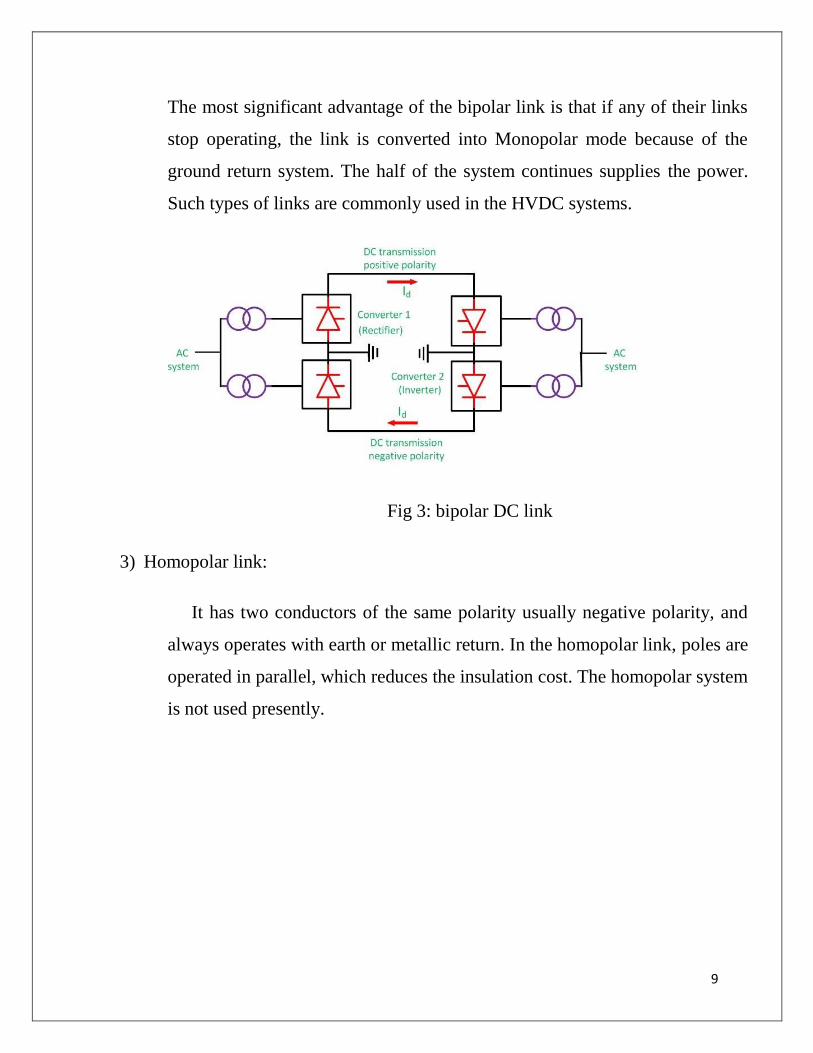
The most significant advantage of the bipolar link is that if any of their links
stop operating, the link is converted into Monopolar mode because of the
ground return system. The half of the system continues supplies the power.
Such types of links are commonly used in the HVDC systems.
Fig 3: bipolar DC link
3) Homopolar link:
It has two conductors of the same polarity usually negative polarity, and
always operates with earth or metallic return. In the homopolar link, poles are
operated in parallel, which reduces the insulation cost. The homopolar system
is not used presently.

10
Fig 3: homopolar DC link
1.5 Typical layout of HVDC system:
The HVDC system has the following main components.
• Converter Station
• Converter Unit
• Converter Valves
• Converter Transformers
• Filters
o AC filter
o DC filter
o High-frequency filter
• Reactive Power Source
• Smoothing Reactor
• HVDC System Pole

11
1.5.1 Converter Station:
The terminal substations which convert an AC to DC are called rectifier
terminal while the terminal substations which convert DC to AC are called
inverter terminal. Every terminal is designed to work in both the rectifier and
inverter mode. Therefore, each terminal is called converter terminal, or rectifier
terminal. A two-terminal HVDC system has only two terminals and one HVDC
line.
Fig 4: schematic diagram of typical HVDC converter station
1.5.2 Converter unit:
The conversion from AC to DC and vice versa is done in HVDC converter stations by
using three-phase bridge converters. This bridge circuit is also called Graetz circuit. In

12
HVDC transmission a 12-pulse bridge converter is used. The converter obtains by
connecting two or 6-pulse bridge in series.
Fig 5: circuit for 6-pulse bridge
1.5.3 Converter transformer:
The converter transformer converts the AC networks to DC networks or vice versa.
They have two sets of three phase windings. The AC side winding is connected to the
AC bus bar, and the valve side winding is connected to valve Bridge. These windings
are connected in star for one transformer and delta to another.
The AC side windings of the two, three phase transformer are connected in stars with
their neutrals grounded. The valve side transformer winding is designed to withstand
alternating voltage stress and direct voltage stress from Valve Bridge. There are
increases in eddy current losses due to the harmonics current. The magnetization in the
core of the converter transformer is because of the following reasons.
• The alternating voltage from AC network containing fundamentals and several
harmonics.
• The direct voltage from valve side terminal also has some harmonics.

13
1.5.4 Filters:
The AC and DC harmonics are generated in HVDC converters. The AC harmonics are
injected into the AC system, and the DC harmonics are injected into DC lines. The
harmonics have the following advantages.
• It causes the interference in telephone lines.
• Due to the harmonics, the power losses in machines and capacitors are
connected in the system.
• The harmonics produced resonance in an AC circuit resulting in over
voltages.
• Instability of converter controls.
The harmonics are minimized by using the AC, DC and high-frequency filters. The
types of filter are explained below in details.
• AC Filters – The AC filters are RLC circuit connected between phase and earth.
They offered low impedances to the harmonic frequencies. Thus, the AC
harmonic currents are passed to earth. Both tuned and damped filters are used.
The AC harmonic filter also provided a reactive power required for satisfactory
operation of converters.
• DC Filters – The DC filter is connected between the pole bus and neutral bus. It
diverts the DC harmonics to earth and prevents them from entering DC lines.

14
Such a filter does not require reactive power as DC line does not require DC
power.
• High-Frequency Filters – The HVDC converter may produce electrical noise in
the carrier frequency band from 20 kHz to 490 kHz. They also generate radio
interference noise in the megahertz range frequencies. High-frequency filters are
used to minimise noise and interference with power line carrier communication.
Such filters are placed between the converter transformer and the station AC
bus.
1.5.5 Converter Valves:
The modern HVDC converters use 12-pulse converter units. The total number of
a valve in each unit is 12. The valve is made up of series connected thyristor modules.
The number of thyristor valve depends on the required voltage across the valve. The
valves are installed in valve halls, and they are cooled by air, oil, water or Freon.
Fig 6:circuit for 12-pulse converter

15
1.5.6 Reactive power source:
Reactive power is required for the operations of the converters. The AC harmonic
filters provide reactive power partly. The additional supply may also be obtained from
shunt capacitors synchronous phase modifiers and static VAR systems. The choice
depends on the speed of control desired.
1.5.7 Smoothing reactor:
Smoothing reactor is an oil filled oil cooled reactor having a large inductance. It is
connected in series with the converter before the DC filter. It can be located either on
the line side or on the neutral side. Smoothing reactors serve the following purposes.
1. They smooth the ripples in the direct current.
2. They decrease the harmonic voltage and current in the DC lines.
3. They limit the fault current in the DC line.
4. Consequent commutation failures in inverters are prevented by smoothing
reactors by reducing the rate of rising of the DC line in the bridge when the
direct voltage of another series connected voltage collapses.
5. Smoothing reactors reduce the steepness of voltage and current surges from
the DC line. Thus, the stresses on the converter valves and valve surge
diverters are reduced.
1.5.8 HVDC System Pole:
The HVDC system pole is the part of an HVDC system consisting of all the
equipment in the HVDC substation. It also interconnects the transmission lines
which during normal operating condition exhibit a common direct polarity with
respect to earth. Thus the word pole refers to the path of DC which has the same

16
polarity with respect to earth. The total pole includes substation pole and
transmission line pole.
1.6 Analysis of Gratez circuit:
The basic module for HVDC converter is the three phase, full wave bridge circuit.
This circuit is also known as a Graetz Bridge. The Graetz Bridge has been universally
used for HVDC converters as it provides better utilization of the converter
transformer and a lower voltage across the valve when not conducting, this voltage is
called Peak Inverse Voltage called PIV and is important for selection of the Thyristor.
The bridge converter is represented by th e equivalent circuit in fig. (3) with
transformer and source impedance with a loss less inductance. Direct current is
assumed to be ripple free and valves as ideal switches with zero resistance when
conducting and infinite resistance when not conducting.
Fig 7: circuit diagram for Graetz Bridge
Let the instantaneous line – to – neutral source voltages be
ea = Em Cos( ωt+60º )
eb = Em Cos( ωt-60º )
ec = Em Cos( ωt-180º)
Then the line-to-line voltages are

17
eac = ea-ec = √3EmCos( ωt+30º )
eba = eb-ea = √3EmCos( ωt-90º )
ecb = ec-eb = √3EmCos( ωt+150º )
For the 6-valve bridge, with zero firing delay, the voltage waveforms across the
thyristors are shown in figure. At any given instant, one thyristor valve on either side is
conducting. The conducting period for the thyristor valve R1 is shown on the diagram.
Fig 8: Thyristor voltage waveforms (α=0)
Fig 9: dc output waveforms (α=0)
It can be shown that for the 6-valve bridge, the total r.m.s. ripple is of the order of
4.2% of the d.c. value (for zero delay α=0 and zero commutation γ=0.
The use of a choke reduces the ripple appearing in the direct current transmitted. If E is
the r.m.s. line-to-line voltage, then if α=0 and γ=0, the direct output voltage is given
by

18
1.6.1 Control angle (Delay angle):
The control angle for rectification (also known as the ignition angle) is the angle by
which firing is delayed beyond the natural take over for the next thyristor. The
transition could be delayed using grid control. Grid control is obtained by
superposing a positive pulse on a permanent negative bias to make the grid positive.
Once the thyristor fires, the grid loses control.
Assuming no commutation (2 thyristors on same side conducting simultaneously
during transfer), the voltage waveforms across the thyristors as shown in figure:
Fig 10: Thyristor voltage waveforms (with delay α)
In this case, the magnitude of the direct voltage output is given by the equation
19
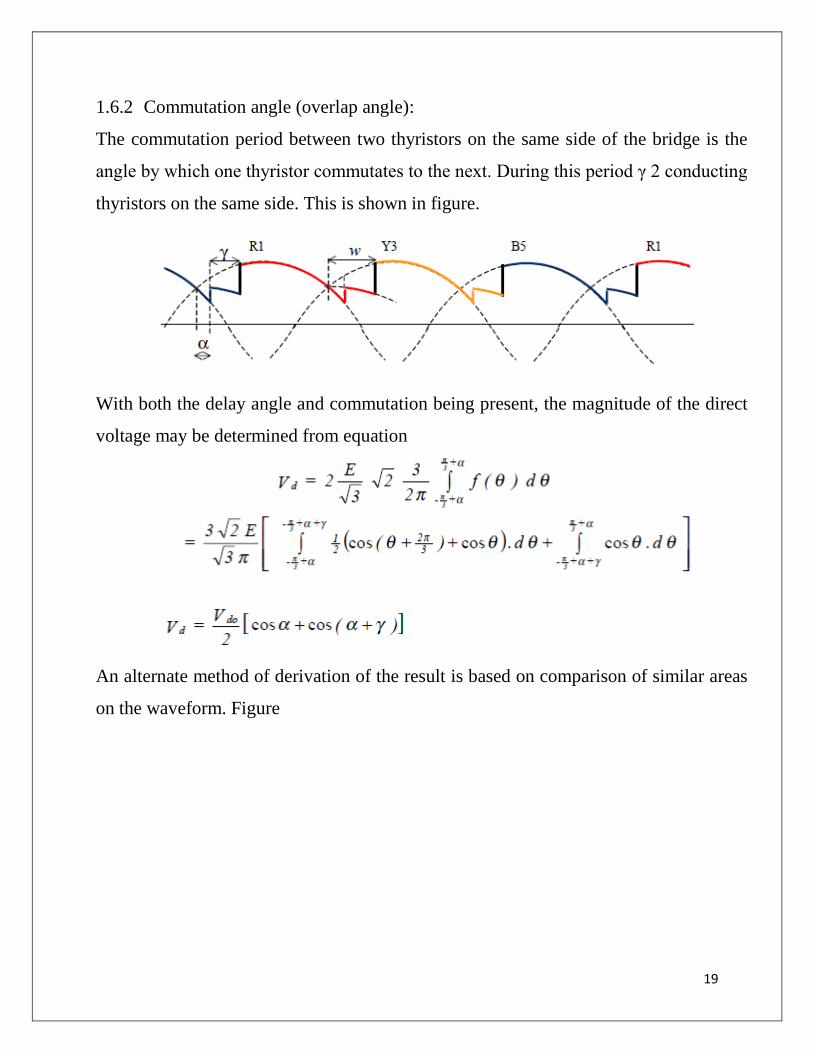
1.6.2 Commutation angle (overlap angle):
The commutation period between two thyristors on the same side of the bridge is the
angle by which one thyristor commutates to the next. During this period γ 2 conducting
thyristors on the same side. This is shown in figure.
With both the delay angle and commutation being present, the magnitude of the direct
voltage may be determined from equation
An alternate method of derivation of the result is based on comparison of similar areas
on the waveform. Figure

20
d.c. output = average value of waveform
In this integral, in graphical form, area A1 can be replaced by area B1. Similarly, area
A2 can be replaced by area B2 and area A3 by area B3. The integral equation then
reduces to the form shown below.
Where √2 E is the peak value of the line voltage. Simplification gives the desired
result as in equation

21
1.6.3 Current Waveforms:
If Commutation is not considered, the current waveforms through each thyristor
(assuming a very high value of inductance Ld in the DC circuit to give complete
smoothing) is a rectangular pulse lasting exactly one-third of a cycle. This is shown in
figure for the cases without delay and with delay.
Fig 11: Thyristor current waveforms
When commutation is considered, the rise and fall of the current waveforms would be
modified as they would no longer be instantaneous, as shown in figure.
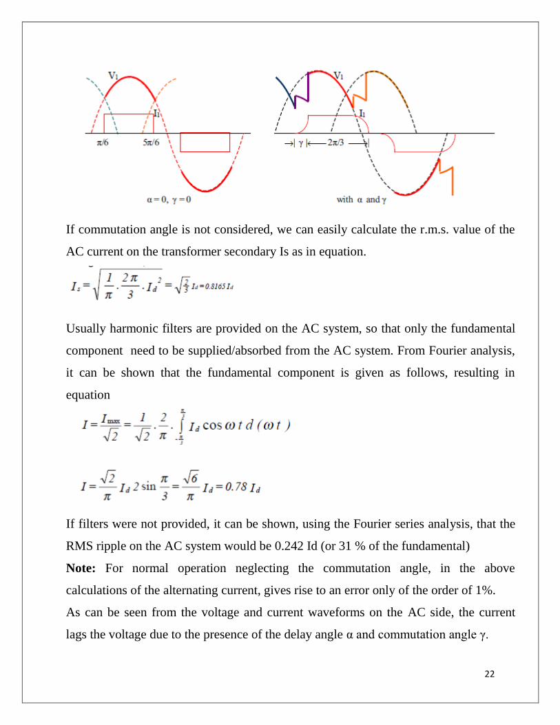
Since each phase has 2 thyristors on the opposite half cycles, the a.c. current waveform
on the secondary side of the transformer has a non-sinusoidal waveform as shown in
figure
22
If commutation angle is not considered, we can easily calculate the r.m.s. value of the
AC current on the transformer secondary Is as in equation.
Usually harmonic filters are provided on the AC system, so that only the fundamental
component need to be supplied/absorbed from the AC system. From Fourier analysis,
it can be shown that the fundamental component is given as follows, resulting in
equation
If filters were not provided, it can be shown, using the Fourier series analysis, that the
RMS ripple on the AC system would be 0.242 Id (or 31 % of the fundamental)
Note: For normal operation neglecting the commutation angle, in the above
calculations of the alternating current, gives rise to an error only of the order of 1%.
As can be seen from the voltage and current waveforms on the AC side, the current
lags the voltage due to the presence of the delay angle α and commutation angle γ.

23
1.6.4 Inversion:
Because the thyristors conduct only in one direction, the current in a convertor cannot
be reversed. Power reversal can only be obtained by the reversal of the direct voltage
(average value) Vd.
For inversion to be possible, a high value of inductance must be present, and the delay
angle α>900 since Vd changes polarity at this angle. The theoretical maximum delay for
inversion would occur at α=1800.
Thus it is common practice to define a period of advance from this point rather than a
delay from the previous cross-over as defined for rectification. Thus we define β=π-α
as the ignition angle for inversion or angle of advance. Similarly extinction angle is
defined as δ =π-w. The definition of the commutation angle γ is unchanged. Thus β=
δ+γ.
Thus we have the practical relationship δ0 < β < π/2.
Fig 12: Thyristor voltage waveforms for inversion
Inversion cannot of course be carried out without a DC power source. Further, to
obtain the necessary frequency for the AC on inversion, the commutation voltage
is obtained from either synchronous machines or from the AC system fed. In
isolated systems, L C circuits may also be sometimes used for the purpose. Figure
shows the thyristor voltage waveforms for inversion.

24
During inversion, each thyristor conducts during the negative half cycle, so that the
direct voltage waveform and the corresponding current have the form shown in
figure.
Fig 13: Direct voltage waveform & thyristor current waveform
The equations derived earlier for the convertor are valid. However, they are usually
written in terms of the variables β and δ instead of α and ω.
Since the direct voltage is always negative during inversion, it is common practice
to omit the negative sign from the expression. It can also be shown that
The power factor of the inverter can be shown to be given by the equation
It is common practice to operate the inverter at a constant extinction angle δ (100 to
200).

25
Unit-II
Converter and HVDC system Control
2.1 Principle of DC link control:
A DC link is a connection which connects a rectifier and an inverter. These
links are found in converter circuits and in VFD circuits. The AC supply of a specific
frequency is converted into DC. This DC, in turn, is converted into AC voltage.
Fig 14: DC Link
The DC link is the connection between these two circuits. The DC link usually has a
capacitor known as the DC link Capacitor. This capacitor is connected in parallel
between the positive and the negative conductors.
The DC capacitor helps prevent the transients from the load side from going back to
the distributor side. It also serves to smoothen the pulses in the rectified DC.
2.2 control characteristics of converter:
The control characteristics of the convertor are the plots of the variation of the
direct voltage against the direct current. These are described in the following sections.

26
2.2.1 Natural Voltage Characteristic (NV) and the Constant Ignition Angle (CIA)
control:
The Natural Voltage Characteristic corresponds to zero delay angle α=0. This
has characteristic equation given by dcd IwLVV )/3(0 . The Constant Ignition Angle
control is a similar characteristic which is parallel to the NV characteristic with a
controllable intercept V0cosα.
2.2.2 Constant Extinction Angle (CEA) control:
The Invertor is usually operated at constant extinction angle. This has the
characteristic equation given by dcd IwLVV )/3(0 . This is shown in below fig.
2.2.3 Constant Current Control (CC):
In a d.c. link it is common practice to operate the link at constant current rather
than at constant voltage. [Of course, constant current means that current is held nearly
constant and not exactly constant]. In constant current control, the power is varied by

27
varying the voltage. There is an allowed range of current settings within which the
current varies.
2.2.4 Full Characteristic of Convertor:
The complete characteristic of each convertor has the N.V. characteristic and
equipped with C.C. control and the C.E.A. control. This is shown in figure for a single
convertor.
2.2.5 Compounding of Convertors:
Figure shows a system of 2 convertors, connected by a hvdc link. Both
convertors are provided with CEA and CC control so that either can work as a rectifier
or an invertor. The compounded characteristics are shown in figure.

28
The margin setting Idm between the current setting Ids for the invertor and for the
rectifier is usually kept at about 10% to 20% of the current setting. The setting of the
convertor operating as rectifier is kept higher than the setting of that as invertor by the
margin setting Idm.
The usual operating point for power transfer is the intersection of the CC control of the
rectifier and the CEA control of the inverter. (For comparison, the characteristics of
convertor B have been drawn inverted). It must also be ensured by proper tap changing
that the N.V. characteristic of the convertor operating in the rectification mode is
higher than the C.E.A. characteristic of the inverter, as Vo of the two ends are not
necessarily equal.
With convertor A operating as rectifier, and convertor B operating as inverter, the
steady state current under all circumstances will remain within the upper limit (Ids +
Idm) and the lower limit Ids. That is, the system direct current will not change by more
than Idm under all operating conditions. By reversing the margin setting Idm, that is
making the setting of convertor B to exceed that of A, power flow can be automatically

29
reversed. Convertor B will then operate as a rectifier and A as an inverter. The reversal
of power occurs as a result of the reversal of polarity of the voltage.
2.2.5 Compounding of Convertors:
The convertor operating equations for voltage Vd and current Id are expressed as
follows.
It is useful to draw the convertor chart in per unit. For this purpose the natural selection
for the base voltage is the maximum direct voltage output Vdo. There is no such
natural current base. Thus it is convenient to select the constant appearing in equation
for current as the base quantity.

30
UNIT-III
HARMONICS FILTERS AND REACTIVE POWER CONTROL
3.1 HARMONIC FILTERS:
The filter arrangements on the AC side of an HVDC converter station have two
main duties:
• to absorb harmonic currents generated by the HVDC converter and thus to
reduce the impact of the harmonics on the connected AC systems, like AC
voltage distortion and telephone interference
• to supply reactive power for compensating the demand of the converter
station
3.1.1 Design Criteria for AC Filters:
3.1.1.1 Reactive Power Requirements:
The reactive power consumption of an HVDC converter depends on the active
power, the transformer reactance and the control angle. It increases with increasing
active power. A common requirement to a converter station is full compensation or
overcompensation at rated load. In addition, a reactive band for the load and voltage
range and the permitted voltage step during bank switching must be determined. These
factors will determine the size and number of filter and shunt capacitor banks.
3.1.1.2 Harmonic Performance Requirements:
HVDC converter stations generate characteristic and non-characteristic
harmonic currents. For a twelve-pulse converter, the characteristic harmonics are of the
order n = (12 * k) ± 1 (k = 1,2,3...). These are the harmonic components that are
generated even during ideal conditions, i.e. ideal smoothing of the direct current,
symmetrical AC voltages, transformer impedance and firing angles. The characteristic
harmonic components are the ones with the highest current level, but other components
may also be of importance. The third harmonic, which is mainly caused by the
negative sequence component of the AC system, will in many cases require filtering.

31
The purpose of the filter circuit is to provide sufficiently low impedances for the
relevant harmonic components in order to reduce the harmonic voltages to an
acceptable level. The acceptance criteria for the harmonic distortion depend on local
conditions and regulations. A commonly used criterion for all harmonic components
up to the 49th order is as follows: Dn individual harmonic voltage distortion of order n
in percent of the fundamental AC busbar voltage (typical limit 1%) Drms total
geometric sum of individual voltage distortion Dn (typical limit 2%)
3.1.1.3 Network Impedance:
The distortion level on the AC busbar depends on the grid impedance as well as
the filter impedance. An open circuit model of the grid for all harmonics is not on the
safe side. Parallel resonance between the filter impedance and the grid impedance may
create unacceptable amplification of harmonic components for which the filters are not
tuned. For this reason, an adequate impedance model of the grid for all relevant
harmonics is required in order to optimize the filter design.
There are basically two methods to include the network impedance in the filter
calculations:
• to calculate impedance vectors for all relevant harmonics and grid conditions
• to assume locus area for the impedance vectors
The modelling of a complete AC network with all its components is very complex and
time-consuming. For this reason, the locus method is very often used. It is based on a
limited number of measurements or calculations. Different locus areas for different
harmonics or bands are often determined to give a more precise base for the harmonic
performance calculation.

32
3.1.2 Requirements to Ratings:
3.1.2.1 Steady state calculation:
The voltage and current stresses of AC filters consist of the fundamental
frequency and harmonic components. Their magnitudes depend on the AC system
voltage, harmonic currents, operating conditions and AC system impedances. The
rating calculations are carried out in the whole range of operation to determine the
highest steady-state current and voltage stresses for each individual filter component.
3.1.2.2 Transient Calculation:
The objective of the transient rating calculation is to determine the highest transient
stresses for each component of the designed filter arrangement. The results of the
transient calculation should contain the voltage and current stresses for each
component, energy duty for filter resistors and arresters, and the insulation levels for
each filter component.
To calculate the highest stresses of both lightning and switching surge type, different
circuit configurations and fault
cases should be studied:
• Single-Phase Ground Fault
The fault is applied on the converter AC bus next to the AC filter. It is
assumed that the filter capacitor is charged to a voltage level corresponding to
the switching impulse protective level of the AC bus arrester.
• Switching Surge
For the calculation of switching surge stresses, a standard wave of
250/2500 with a crest value equal to the switching impulse protective level of
the AC bus arrester is applied at the AC converter bus.

33
3.1.2.3 Filter Energization:
The AC filter is assumed to be energized at the moment for the maximum AC
bus peak voltage. This case is decisive for the inrush currents of AC filters.
3.1.2.4 Fault Recovery after Three-Phase Ground Fault:
Various fault-clearing parameters should be investigated to determine the maximum
energy stresses for AC filter arresters and resistors. The worst case stresses are
achieved if the HVDC converters are blocked after fault initiation, while the AC filters
remain connected to the AC bus after fault clearing and recovery of the AC system
voltage. In this case, a temporary overvoltage with high contents of non-characteristic
harmonics will occur at the AC bus due to the effects of load rejection, transformer
saturation and resonance between filter and AC network at low frequency.
3.1.3 DC Filter Circuits:
Harmonic voltages which occur on the DC side of a converter station cause AC
currents which are superimposed on the direct current in the transmission line. These
alternating currents of higher frequencies can create interference in neighbouring
telephone systems despite limitation by smoothing reactors. DC filter circuits, which
are connected in parallel to the station poles, are an effective tool for combating these
problems. The configuration of the DC filters very strongly resembles the filters on the
AC side of the HVDC station. There are several types of filter design. Single and
multiple-tuned filters with or without the high-pass feature are common. One or several
types of DC filter can be utilized in a converter station.
3.1.3.1 Design Criteria for DC Filter Circuits:
The interference voltage induced on the telephone line can be characterized by
the following equation:

34
The equivalent disturbing current combines all harmonic currents with the aid of
weighting factors to a single interference current. With respect to telephone
interference, it is the equivalent to the sum of all harmonic currents. It
also encompasses the factors which determine the coupling between the HVDC and
telephone lines:
• Operating mode of the HVDC system (bipolar or monopolar with metallic or
ground return)
• Specific ground resistance at point x the intensity of interference currents is
strongly dependent on the operating condition of the HVDC. In monopolar
operation, telephone interference is significantly stronger than in bipolar
operation.

35
Unit –IV
Introduction to FACTS:
4.1 INTRODUCTION:
FACTS ie., Flexible AC transmission system incorporate power electronic based
static controllers to control power (both active and reactive power needed ) and
enhance power transfer capability of the AC lines . Let Bus 1and Bus 2shown in fig 1:
represent two AC systems where in power is to be transmitted from 1 to 2through a
line of impedance r+jx.
By changing the effective value of ‘x’ ,the power transmitted can be increased or
decreased .Further it modifies reactive power needed.
• Increase or decrease of ‘x’ will change value.
• Maximum power that can be transmitted is obtained when δ= (provided are
fixed).
• The FACTS technology is not a single high-power controller but rather a
collection of controllers. which can be applied individually or in coordination
with others to control one or more of the interrelated system parameters.
• The parameters that govern the operation of transmission system including .
o Series impedance
o Shunt impedance
o Current

36
o Voltage
o Phase and
o Damping of oscillations at various frequencies below the required system
frequency.
• The FACTS controllers can enable a line to carry power closer to its thermal
rating.
• In flexible (or) controllable AC systems, the controllable parameters are
a) Control of line reactance.
b) Control of phase angle δ when it is not large(which controls the active
power flow)
c) Injecting voltage in series with line and at 90°phase with line current
ie.. injection of reactive power in series. This will control active power
flow.
d) Injecting voltage in series with line but at variable phase angle . This
will control both active & reactive power flow .
e) Controlling the magnitude of either V1or V2.
f) Controlling or variation of line reactance with a series controller and
regulating the voltage with a shunt controller. This can control both active
and reactive power.
4.2 Flow of Power in A.C Systems:
In AC power systems the electrical generation and load must balance at al times .To
some extent, the electrical system is self –regulating. In generation is less than load ,the
voltage and frequency drop. However there is only a few percent margin for such a self
regulation .[If voltage propped up with reactive power support ,then the load will go up
and consequently frequency will keep dropping and system will collapse .If there is
inadequate reactive power support, the system can have voltage collapse. When

37
adequate generation is available , active power flows from the surplus generation areas
to defect areas through all parallel paths available which frequently involves EHV
(extra high voltage )and medium voltage lines .
4.2.1 Power Flow in a parallel path system:
Consider power flow through two parallel paths from a surplus generation area
to a defect generation area on right as shown in fig
With out any control ,power flow is based on the inverse of various transmission line
impedances.
A part from ownership and contractual issues, lines carry how much power. It is likely
that lower impedance line may become overloaded and there by limit the loading on
both paths even though the higher impedance path is not fully loaded. Fig: shows the
same to paths, but one of these has HVDC transmission.
With HVDC, power flows as ordered by the operator because with HVDC power
electronic converters power is electronically controlled.

38
An HVDC line can also help the parallel AC transmission line to maintain stability.
However, HVDC is expensive for general use ,and is considered when long distances
are involved .
Fig 3: and Fig 4: show one of the parallel transmission lines with different types of
series type FACTS controllers.
4.2.2 Power Flow in a meshed system:
Consider two generators at two different locations are sending power to a load
centre through a network consisting of three lines in a meshed connection as shown in
fig:
Fig: (a) Power flow in a mesh network
• Suppose the lines AB,BC and AC have continuous ratings of 1000 MW
,1250 MW and 2000 MW
• These lines have energy ratings of twice those numbers for a sufficient
time to allow rescheduling of incase of loss of one of these lines.

39
• If one of the generators is generating 2000MW and the other 1000MW, a
total of 3000 MW would be delivered to the load centre.
• For impedances shown three lines would carry 600,1600 and 1400 MW
respectively as shown in fig:(a);
• If a capacitor of reactance -5Ω at synchronous frequency is inserted in one
line as shown in fig: (b).It reduces the line’s impedance from 10Ω to5Ω.
Fig : (b) Power of flow in a mesh network with thyristor controlled from the figure ,it
is clear that
Power flow through AB will be 250 MW
BC will be 1250 MW
AC will be 1750 MW respectively
• Although, this capacitor could be modular and mechanically switched ,the
number of operations would be limited by wear on mechanical components.
• There complications may arise if the series capacitor is mechanically
controlled. A series capacitor in a line may lead to sub synchronous resonance.
• A transistor controlled series capacitor (TCSC) can greatly enhance the stability
of the network. It is practical that series compensation must be partly
mechanically controlled and constraints at the least cost.
40
• By increasing the impedance of one of the lines in the same meshed
configuration the power flow can be controlled.
4.3 BASIC TYPES OF FACTS CONTROLLERS:
In general FACTS controllers can be divided into four categories.
• Series controllers
• Shunt controllers
• Combined Series- series controllers
• Combined series- shunt controllers
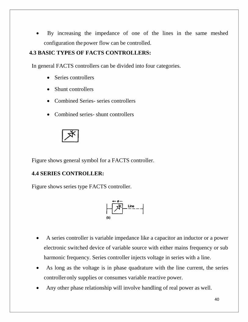
Figure shows general symbol for a FACTS controller.
4.4 SERIES CONTROLLER:
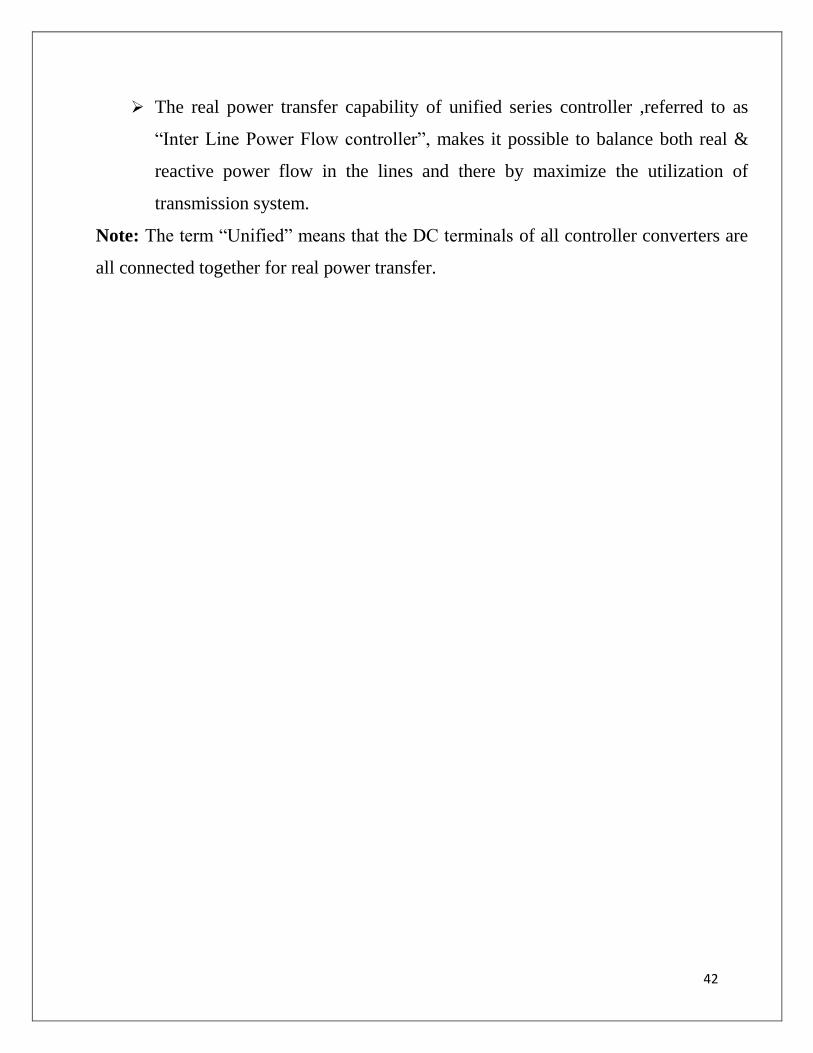
Figure shows series type FACTS controller.
• A series controller is variable impedance like a capacitor an inductor or a power
electronic switched device of variable source with either mains frequency or sub
harmonic frequency. Series controller injects voltage in series with a line.
• As long as the voltage is in phase quadrature with the line current, the series
controller only supplies or consumes variable reactive power.
• Any other phase relationship will involve handling of real power as well.

41
4.5 SHUNT CONTROLLER :
Fig: shows shunt FACTS controller
• A shunt controller can be variable impedance, variable source or
combination of both .
• Shunt controller inject current into the line (system) at the point of
connection.
• As long as the injected current is in quadrature with line voltage, shunt
controller only supplies or consumes variable reactive power.
• Any other phase relationship will involve handling of real power as well.
Fig: shows series-series FACTS controller
This could be a combination of separate series controllers which are controlled in a co
-ordinate manner, in multi-line transmission systems.
➢ Series controllers provide independent series reactive compensation for each
line but also transfer real power among the lines via the power link.
42
➢ The real power transfer capability of unified series controller ,referred to as
“Inter Line Power Flow controller”, makes it possible to balance both real &
reactive power flow in the lines and there by maximize the utilization of
transmission system.
Note: The term “Unified” means that the DC terminals of all controller converters are
all connected together for real power transfer.

43
UNIT-V
STATIC SERIES AND COMBINES COMPENSATORS
5.1 COMBINED SERIES –SHUNT CONTROLLERS :
Figures shows combinations of series and shunt controllers ,which are controlled in a
co-ordinate manner .
➢ The combined shunt and series controllers inject current into the system with
the shunt part of the controller and voltage in series in the line with series part
of controller.
When shunt and series controllers are unified .there can be a real power
exchange between the series and shunt controllers via the power link.
5.2 SHUNT CONNECTED CONTROLLERS:
(i) Static Synchronous Compensators (STATCOM): A static synchronous generator
operated as a shunt connected static var compensator whose4 capacitive or inductive
output current can be controlled independent of the AC system voltage.
STATCOM is one of the key FACTS controllers. It can be based on a voltage sourced
or current sourced converter.

44
Figure 1(a) shows a simple one-line diagram of STATCOM based on a voltage
sourced converter and a current sourced converter.STATCOM can be designed to also
act as an active filter to absorb system harmonics.
(ii) Static Var Compensator (SVC): A shunt connected static var generator or absorber
whose output is adjusted to exchange capacitive or inductive current so as to maintain
or control specific parameters of the electrical power system.
This is a general term for a thyristor controlled or thyristor switched reactor and/or
thyristor switched capacitor or combination. SVC is based on thyristors without gate
turn-off capability. It includes separate equipment for leading and lagging vars, the
thyristor controlled or thyristor switched reactor for absorbing reactive power on
thyristor switched capacitor for supplying the reactive power.
(iii) Thyristor Controlled Reactor (TCR): A shunt connected thyristor controlled
inductor whose effective reactance is varied in a continuous manner by partial-
conduction control of the thyristor valve.

45
subset of SVC in which conduction time and hence, current in a shunt reactor is
controlled by a thyristor based ac switch with firing angle control.
(iv) Thyristor Switched Reactor (TSR): A shunt connected thyristor-switched inductor
whose effective reactance is varied in a stepwise manner by full-or zero-conduction
operation of the thyristor valve. TSR is another subset of SVC. TSR is made up of
several shunt connected inductors which are switched in and out by thyristor switches
without any firing angle controls in order to achieve the required step changes in the
reactive power consumed from the system. Use of thyristor switches without firing
angle control results in lower cost and losses, but without a continuous control.
(v) Thyristor Switched Capacitor (TSC): A shunt connected thyristor-switched
capacitor whose effective reactance is varied in a stepwise manner by full-or zero-
conduction operation of the thyristor valve.
TSC is also a subset of SVC in which thyristor based ac switches are used to switch in
and out shunt capacitors units, in order to achieve the required step change in the
reactive power supplied to the system. Unlike shunt reactors, shunt capacitors cannot
be switched continuously with variable firing angle control.
(vi) Static VAR System (SVS): A combination of different static and mechanically-
switched VAR compensators whose outputs are coordinated..
5.3 SERIES CONNECTED CONTROLLERS
Static Synchronous Series Compensator (SSSC): A static synchronous generator
operated without an external electric energy source as a series compensator whose
output voltage is quadrature with, and controllable independently of, the line current
for the purpose of increasing or decreasing the overall reactive voltage drop across the

46
line and thereby controlling the transmitted electric power. The SSSC may include
transiently rated energy storage or energy absorbing devices to enhance the dynamic
behavior of the power system by additional temporary real power compensation, to
increase or decrease momentarily, the overall real (resistive) voltage drop across the
line.
SSSC is one of the most important FACTS controllers. It is like a STATCOM,
except that the output ac voltage is in series with the line. It can be based on a
voltage-sourced converter or current- sourced converter. Battery-storage or
superconducting magnetic storage can also be connected to a series controller to inject
a voltage vector of variable angle in series with the line.
(i) Interline Power Flow Controller (IPFC):The combination of two or more Static
synchronous Series Compensators which are coupled via a common dc link to
facilitate bi-directional flow of real power between the ac terminals of the SSSCs, and
are controlled to provide independent reactive compensation for the adjustment of real
power flow in each line and maintain the desired distribution of reactive power flow
among the lines. The IPFC structure may also include a STATCOM, coupled to the
IPFC’s common dc link, to provide shunt reactive compensation and supply or absorb
the overall real power deficit of the combined SSSCs.
(ii) Thyristor Controlled Series Capacitor (TCSC): A capacitive reactance compensator
which consists of a series capacitor bank shunted by a thyristor-controlled reactor in

47
order to provide a smoothly variable series capacitive reactance.
The TCSC is based on thyristors without the gate turn-off capability. It is an
alternative to SSSC above and like an SSSC, it is a very important FACTS Controller.
A variable reactor such as a Thyristor- Controlled Reactor (TCR) is connected across
a series capacitor.
(iii) Thyristor-Switched Series Capacitor (TSSC): A capacitive reactance compensator
which consists of a series capacitor bank shunted by a thyristor-switched reactor to
provide a stepwise control of series capacitive reactance. Instead of continuous control
of capacitive impedance, this approach of switching inductors at firing angle of 90
degrees or 180 degrees but without firing angle control, could reduce cost and losses
of the Controller. It is reasonable to arrange one of the modules to have thyristor
control, while others could be thyristor switched.
(iv) Thyristor-Controlled Series Reactor (TCSR):
An inductive reactance compensator which consists of a
series reactor shunted by a thyristor controlled reactor in order to provide a smoothly
variable series inductive reactance. When the firing angle of the thyristor controlled
reactor is 180 degrees, it stops conducting, and the uncontrolled reactor acts as a fault
current limiter. As the angle decreases below 180 degrees, the net inductance decreases
until firing angle of 90 degrees, when the net inductance is the parallel combination of
the two reactors. As for the TCSC, the TCSR may be a single large unit or several
smaller series units.
(v) Thyristor-Switched Series Reactor (TSSR): An inductive reactance compensator
which consists of a series reactor shunted by a thyristor-controlled switched reactor in
order to provide a stepwise control of series inductive reactance. This is a complement
of TCSR, but with thyristor switches fully on or off (without firing angle control) to
achieve a combination of stepped series inductance.

48