fundamentals of electrical power measurement · pdf file · 2017-09-22measurement...
TRANSCRIPT

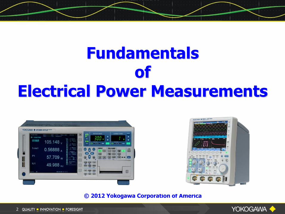
Fundamentals of
Electrical Power Measurement
Bill Gatheridge
Product Manager
© 2012 Yokogawa Corporation of America
1
Fundamentals of
Electrical Power Measurements
© 2012 Yokogawa Corporation of America
2

3
Kristina Coppolino Marketing Specialist Yokogawa Corporation of America Newnan, GA [email protected] 1-800-888-6400 ext 5437 tmi.yokogawa.com
Host

Yokogawa Webinar – Housekeeping Issues
Teleconference Information Call-in toll-free number (US/Canada): 1-877-668-4490 Call-in toll number (US/Canada): 1-408-792-6300 Access Code – 754 756 534
PC’s Speakers - Audio Broadcast To hear the audio through your PC, select the Communicate Tab and Join the Audio Broadcast.
Recorded Presentation A recording of this presentation will be posted under our technical library of our web page.
Poll Questions Please take a few minutes to answer the 5 poll questions presented later in the presentation.
4

Presenter
Bill Gatheridge Product Manager Yokogawa Corporation of America Newnan, GA 1-800-888-6400 Ext 5454 [email protected] tmi.yokogawa.com
5

Providing Solutions
and
Education
for
Electrical Power Measurements
6

Overview - What We Plan To Do
Part I: Electrical Power Measurements
Review Some Basics
Power Measurements Using a Precision
Power Analyzer
Single-Phase Power Measurements
Current Sensors
Three-Phase Power Measurements
2 & 3 Wattmeter Method
7
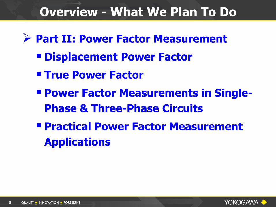
Overview - What We Plan To Do
Part II: Power Factor Measurement
Displacement Power Factor
True Power Factor
Power Factor Measurements in Single-
Phase & Three-Phase Circuits
Practical Power Factor Measurement
Applications
8

Part III: Power Measurements using a
Digital Oscilloscope
How to properly use a Digital Oscilloscope to
make Electrical Power Measurements
Some “Do’s” and “Don’ts” Measurement Examples Comparison of a DSO and a Power Analyzer
Answer your questions concerning
Electrical Power Measurements
Overview - What We Plan to Do
9
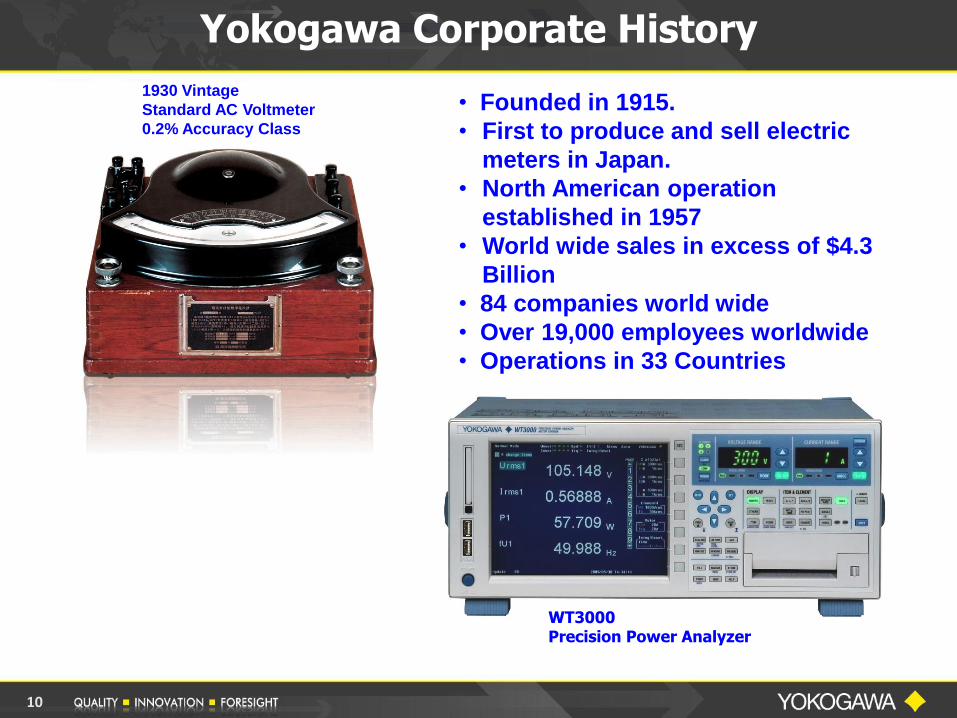
Yokogawa Corporate History
• Founded in 1915.
• First to produce and sell electric
meters in Japan.
• North American operation
established in 1957
• World wide sales in excess of $4.3
Billion
• 84 companies world wide
• Over 19,000 employees worldwide
• Operations in 33 Countries
1930 Vintage
Standard AC Voltmeter
0.2% Accuracy Class
WT3000 Precision Power Analyzer
10

Yokogawa Corporation of America Newnan, GA
Yokogawa Corporation of America
11

Yokogawa Corporation of America
12
PART I
ELECTRICAL POWER
MEASUREMENTS
13
First let’s Review some Basics
14

Review OHM’S LAW
15
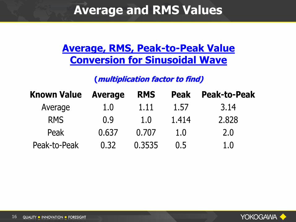
Average and RMS Values
Average, RMS, Peak-to-Peak Value Conversion for Sinusoidal Wave
(multiplication factor to find)
Known Value Average RMS Peak Peak-to-Peak
Average 1.0 1.11 1.57 3.14
RMS 0.9 1.0 1.414 2.828
Peak 0.637 0.707 1.0 2.0
Peak-to-Peak 0.32 0.3535 0.5 1.0
16

Average and RMS Values
17

Electrical Power Measurements
18

Measurement of Power
What’s A Watt ?
DC Source:
AC Source:
W = V x A
W = V x A x PF
A unit of Power equal to one Joule of Energy per Second
19

Measurement of Power
AC Power Measurement
Active Power:
Watts P = Vrms x Arms x PF
Also sometimes referred to as True Power or Real Power
Apparent Power:
Volt-Amps S = Vrms x Arms
20

Watts P = Vrms x Arms x PF = Urms1 x Irms1 x λ1
Volt-Amps S = Vrms x Arms = Urms1 x Irms1
Measurement of AC Power
21

Measurement of Power
Digital Power Analyzers are entirely electronic and use some form of DIGITIZING TECHNIQUE to convert analog signals to digital form.
higher end analyzers use DIGITAL SIGNAL PROCESSING techniques to determine values
Digital Power Oscilloscopes use SPECIAL FIRMWARE to make true power measurements
Digitizing instruments are somewhat RESTRICTED because it is a sampled data technique
Many Power Analyzers and Power Scopes apply FFT algorithms for additional power and harmonic analysis
22
Measurement of Power
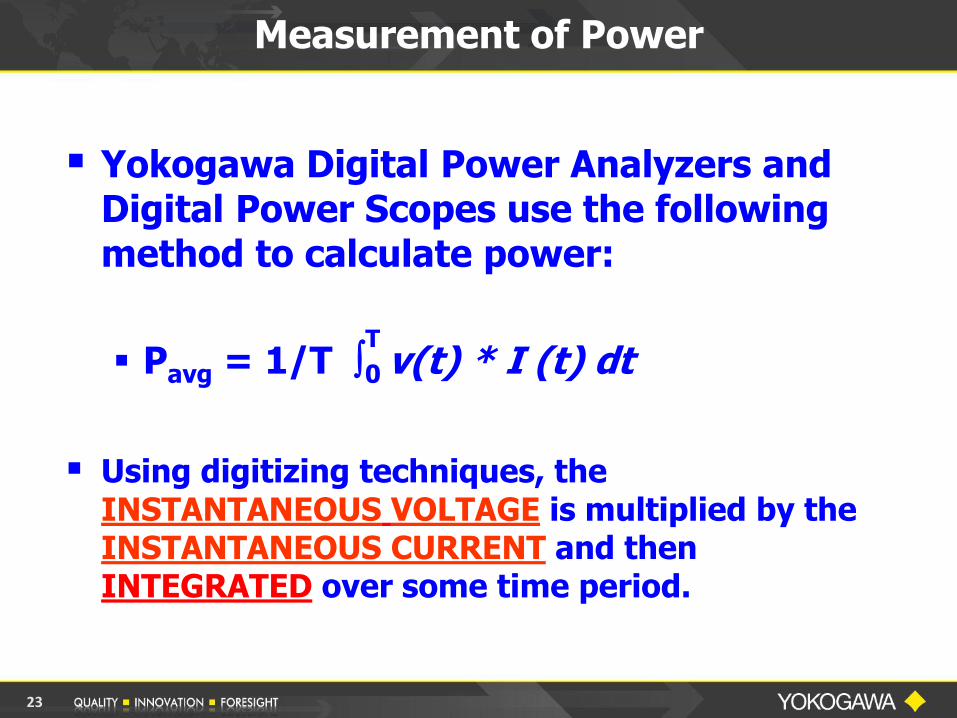
Yokogawa Digital Power Analyzers and Digital Power Scopes use the following method to calculate power:
Pavg = 1/T 0 v(t) * I (t) dt
Using digitizing techniques, the
INSTANTANEOUS VOLTAGE is multiplied by the INSTANTANEOUS CURRENT and then INTEGRATED over some time period.
T
23
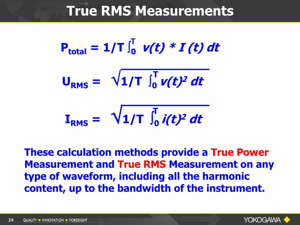
These calculation methods provide a True Power Measurement and True RMS Measurement on any type of waveform, including all the harmonic content, up to the bandwidth of the instrument.
T
True RMS Measurements
URMS = 1/T 0 v(t)2 dt
Ptotal = 1/T 0 v(t) * I (t) dt
T
T IRMS = 1/T 0
i(t)2 dt
24
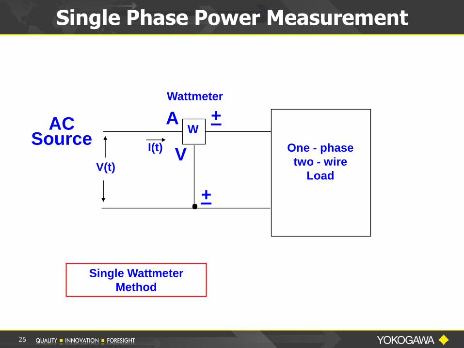
Single Phase Power Measurement
Wattmeter
One - phase
two - wire
Load V(t)
I(t)
.
A +
V
+
AC Source
Single Wattmeter
Method
W
25

Measurement of Power
Single-Phase Two-Wire System
The voltage and current detected by the
METER are the voltage and current
applied directly to the Load.
The indication on the Meter is the POWER
being dissipated by the load.
26
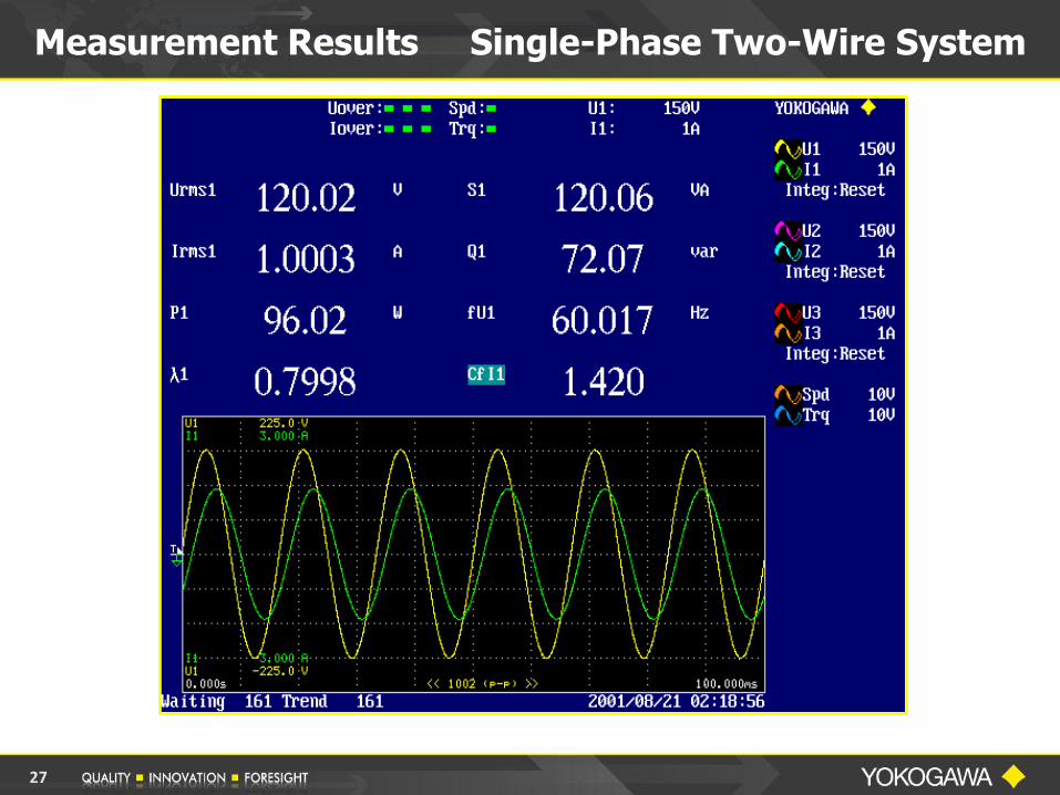
Measurement Results Single-Phase Two-Wire System
27
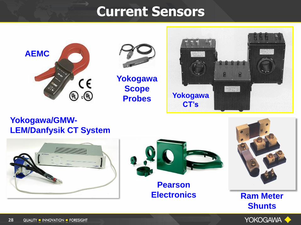
Current Sensors
Ram Meter
Shunts
Yokogawa
CT’s
AEMC
Yokogawa/GMW-
LEM/Danfysik CT System
Yokogawa
Scope
Probes
Pearson
Electronics
28
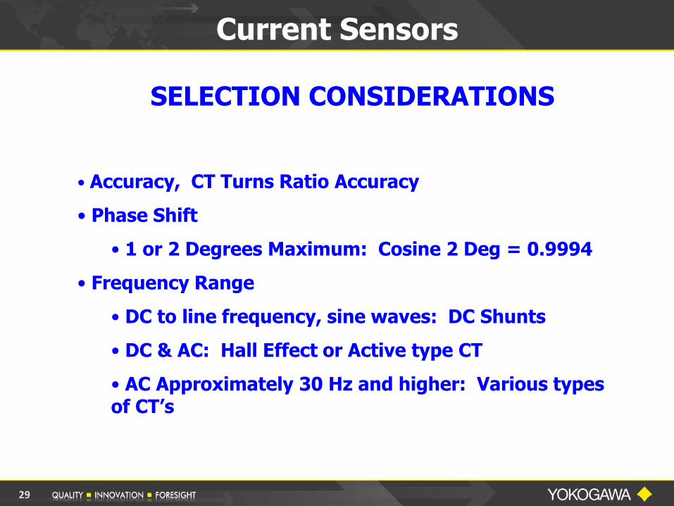
Current Sensors
SELECTION CONSIDERATIONS
• Accuracy, CT Turns Ratio Accuracy
• Phase Shift
• 1 or 2 Degrees Maximum: Cosine 2 Deg = 0.9994
• Frequency Range
• DC to line frequency, sine waves: DC Shunts
• DC & AC: Hall Effect or Active type CT
• AC Approximately 30 Hz and higher: Various types of CT’s
29

Current Sensors
SELECTION CONSIDERATIONS
• Instrument Compatibility
• Output: Millivolts/Amp, Milliamps/Amp; or Amps
• Impedance and Load, Burden
• Scope Probes - - CAUTION! Use on Scopes, NOT Power Analyzers
• Physical Requirements
• Size
• Connections: Clamp-On or Donut type
• Distance from Load to Instrument
30

Current Sensors
A WORD OF CAUTION
NEVER Open Circuit the Secondary side of a Current Transformer while it is energized!
• This could cause serious damage to the CT and could
possibly be harmful to equipment operators.
• A CT is a Current Source.
• By Ohm’s Law E = I x R
• When R is very large, E becomes very high
• The High Voltage generated inside the CT will cause a magnetic saturation of the core, winding damage, or other damage which could destroy the CT.
31

Single-Phase Three-Wire Power Measurement
One - phase
three - wire
Load
Wattmeter 1
V(t)
I(t)
V(t)
I(t)
Wattmeter 2
N .
PT = W1 + W2
A
+
AC Source
A
+
+
V
V
Two Wattmeter
Method
L1
L2
W
W
32

Measurement of Power
Single-Phase Three-Wire System
(Split Phase)
The voltage and current detected by the METERS are the voltage and current applied directly to the Load.
The indication on EACH METER is the power being
delivered by the LINE to which the meter is connected.
The total power dissipated by the load is the ALGEBRAIC
SUM of the two indications.
33
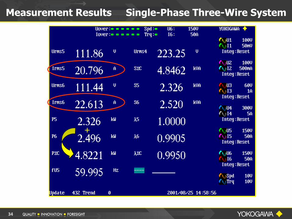
Measurement Results Single-Phase Three-Wire System
+
34
Measurement Results Single-Phase Three-Wire System
35

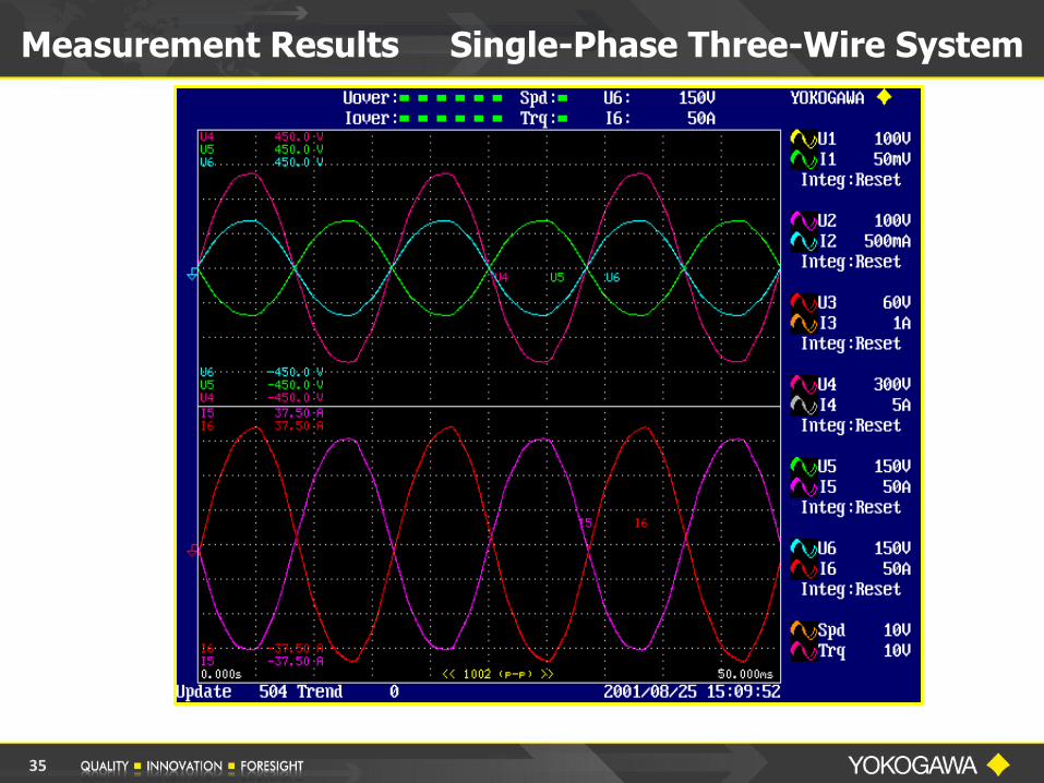
Measurement Results Single-Phase Three-Wire System
36
Measurement of Power
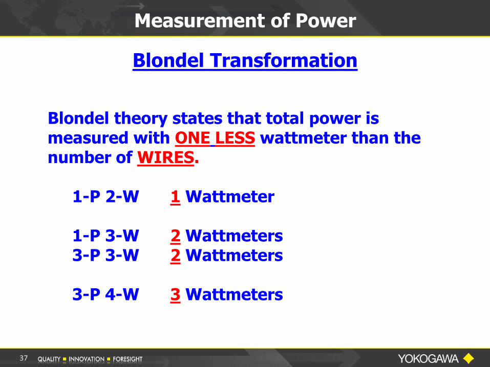
Blondel theory states that total power is measured with ONE LESS wattmeter than the number of WIRES. 1-P 2-W 1 Wattmeter 1-P 3-W 2 Wattmeters 3-P 3-W 2 Wattmeters 3-P 4-W 3 Wattmeters
Blondel Transformation
37
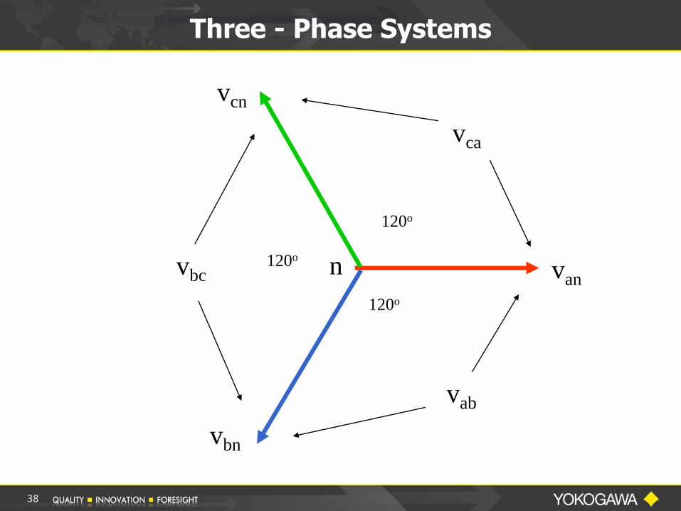
Three - Phase Systems
van
vbn
vcn
120o
120o
120o n
vab
vbc
vca
38
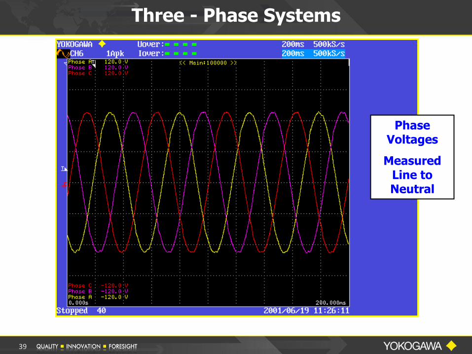
Phase Voltages
Measured Line to Neutral
Three - Phase Systems
39
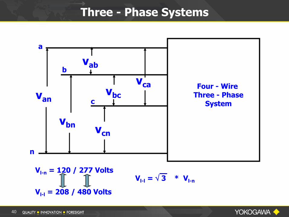
Three - Phase Systems
a
b
c
n
van
vbn vcn
vab
vbc vca Four - Wire
Three - Phase System
Vl-n = 120 / 277 Volts
Vl-l = 208 / 480 Volts
Vl-l = 3 * Vl-n
40
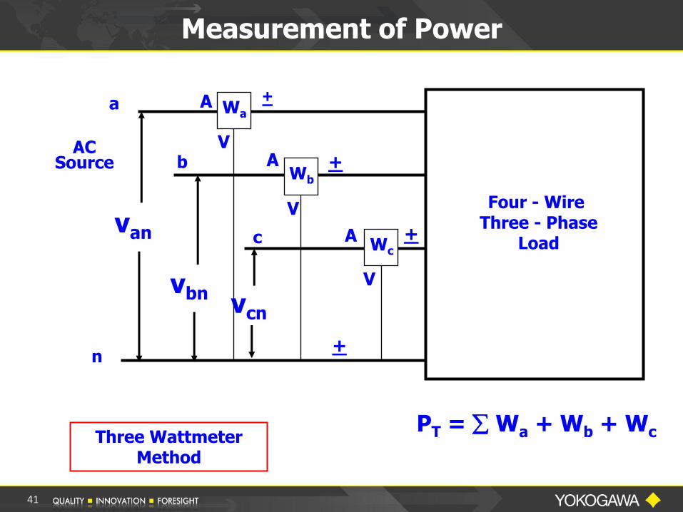
Measurement of Power
a
b
c
n
van
vbn vcn
Four - Wire Three - Phase
Load
Wa
Wb
Wc
PT = Wa + Wb + Wc
AC Source
A
A
+
A
Three Wattmeter Method
+
+
+
V
V
V
41

Measurement of Power
Three-Phase Four-Wire System
The three meters use the FOURTH wire as the common voltage REFERENCE.
Each meter indicates the PHASE power.
The TOTAL POWER for the three phases is the ALGEBRAIC SUM of the three meters.
In essence, each meter measures a SINGLE PHASE of the three phase system.
42
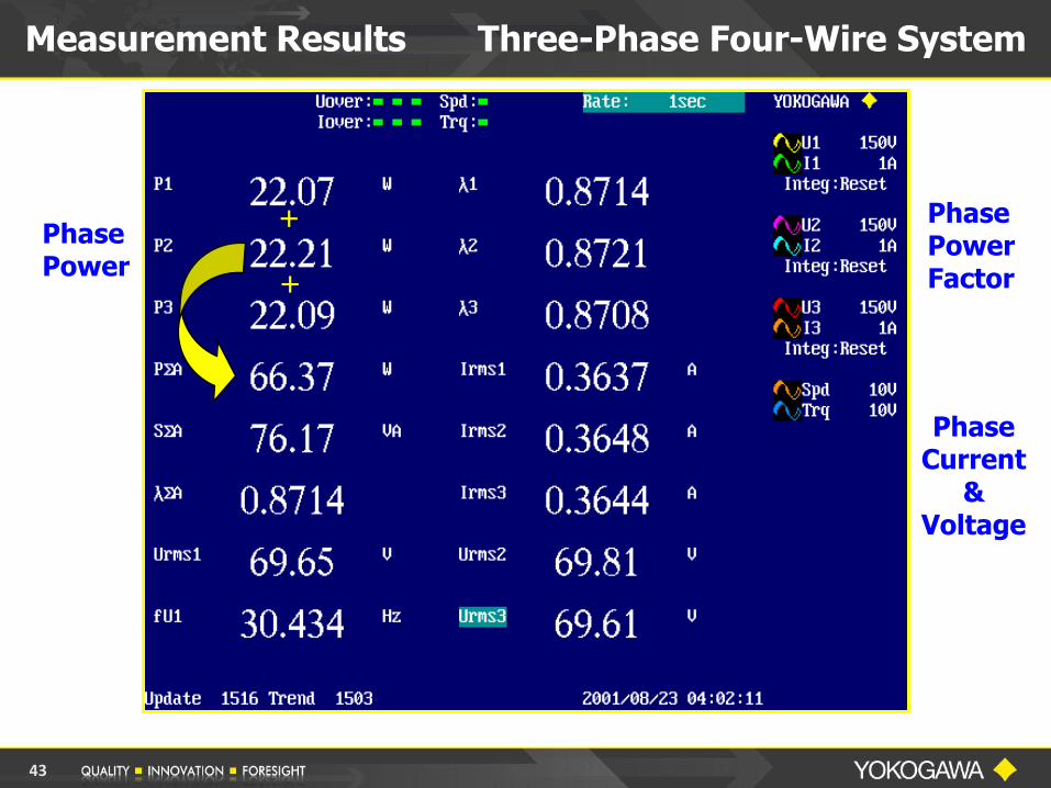
Measurement Results Three-Phase Four-Wire System
Phase Power
Phase Power Factor
Phase Current
& Voltage
+
+
43
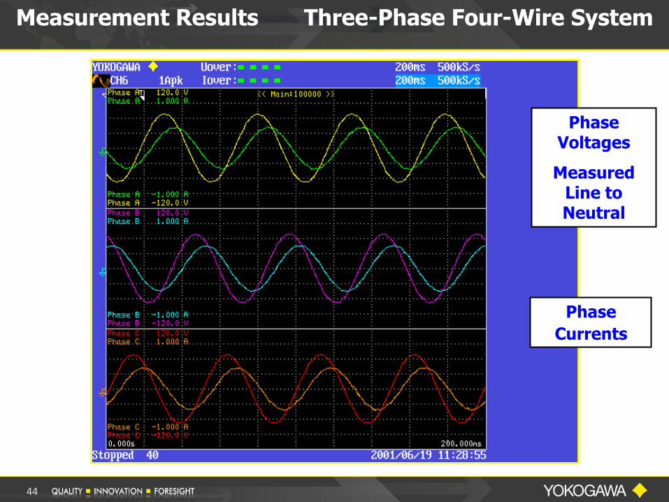
Phase Voltages
Measured Line to Neutral
Phase
Currents
Measurement Results Three-Phase Four-Wire System
44
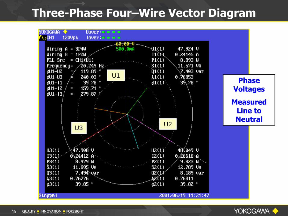
Three-Phase Four–Wire Vector Diagram
U1
U2 U3
Phase Voltages
Measured Line to Neutral
45

Three-Phase Three-Wire Systems
a
b
c
vab
vcb
vca Three - Wire Three - Phase
System
46
Measurement of Power
Remember
Blondel’s Transformation
. . . total power is measured with ONE LESS wattmeter than the number of WIRES.
47

Measurement of Power 3P-3W System
AC Source
a
b
c
vac
vcb
vab
Three - Wire Three - Phase
Load
Wa
Wb
Wc
A
A
A
V
V
+
V
+
+
+
+
+
Two Wattmeter Method
Three - Phase Three - Wire System With Two Meters
PT = Wa + Wb
48

Measurement of Power
Three-Phase Three-Wire System
The wattmeters used for this connection each measure the PHASE CURRENTS
The measured voltages are the LINE-TO-LINE values, NOT Phase Voltage.
Thus the indications on each of the meters IS NOT the power delivered by the PHASE of the measured current.
This configuration is a very NON-INTUITIVE connection!
49

Three-Phase Three-Wire System
The method yields the Total Power as the Sum of the TWO METERS in Phase 1 and 2. Note that NONE of the meters is indicating the correct PHASE POWER.
+
50

The Two Wattmeter technique tends to cause less confusion than the three meter technique since there is no expectation that a meter will give an accurate phase indication.
However, with the Yokogawa Power Analyzers, on a 3-Phase 3-Wire System, use the 3V-3A wiring method. This method will give all three Voltages and Currents, and correct Total Power, Total Power Factor and VA Measurements on either Balanced or Unbalanced 3-Wire system.
Electrical Power Measurements
51

Three-Phase Three-Wire System With Three Meters
The method yields the Total Power as the Sum of the TWO METERS in Phase 1 and 2. Note that NONE of the meters is indicating the correct PHASE POWER.
52
53
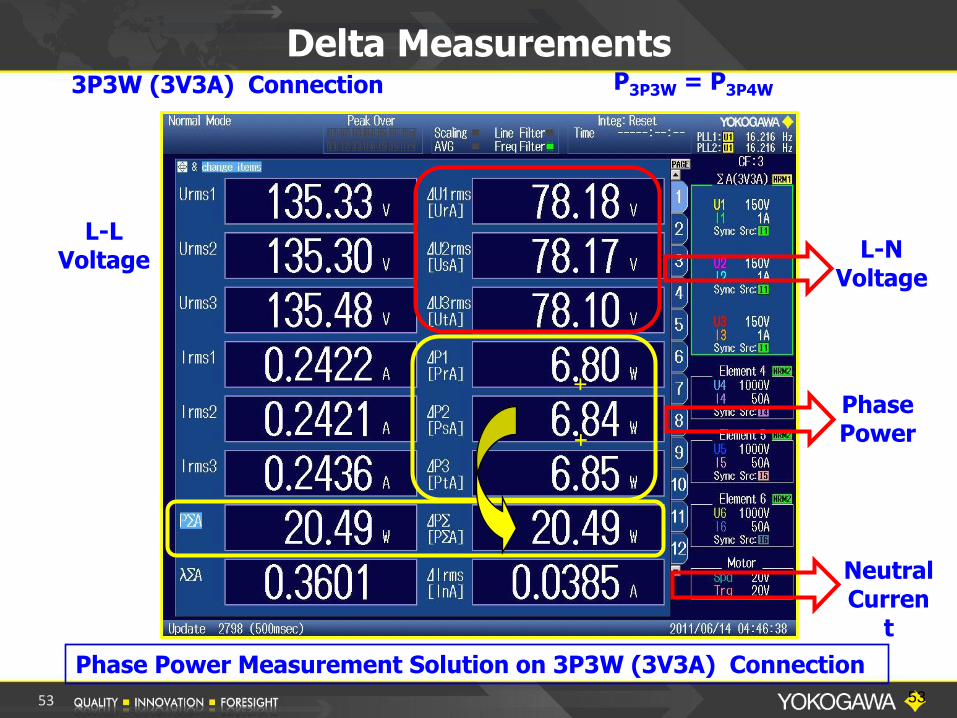
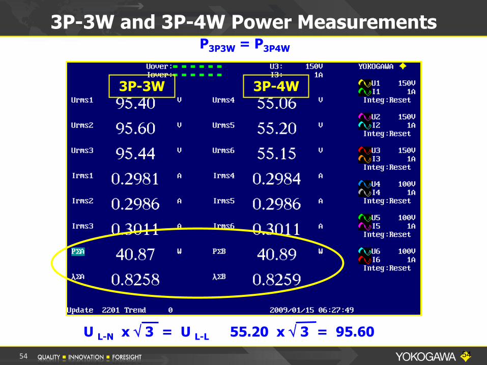
Delta Measurements P3P3W = P3P4W
L-N Voltage
Phase Power
L-L Voltage
+
+
3P3W (3V3A) Connection
Neutral Curren
t
Phase Power Measurement Solution on 3P3W (3V3A) Connection
53
54
3P-3W and 3P-4W Power Measurements
U L-N x 3 = U L-L 55.20 x 3 = 95.60
P3P3W = P3P4W
3P-3W 3P-4W
54
PART II
POWER FACTOR
MEASUREMENTS
55

56
Power Factor Measurement
If Power Factor is the Cosine of the Angle between Voltage and Current, then how do we measure Power Factor on a Three Phase Circuit?
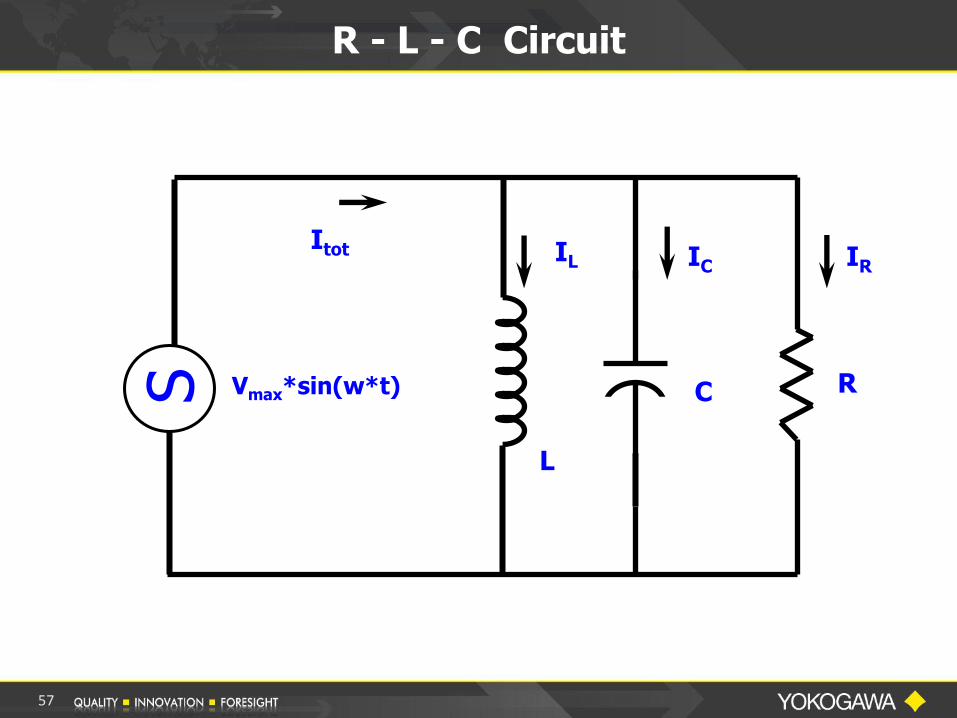
R - L - C Circuit
Vmax*sin(w*t)
Itot IC IR
R C
IL
L
S
57
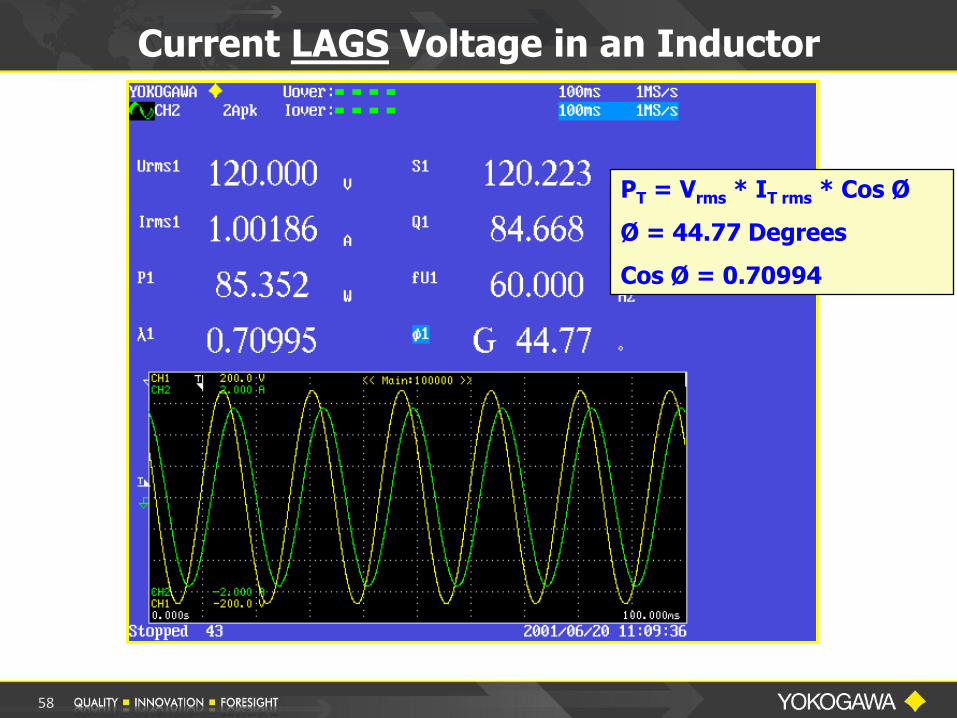
Current LAGS Voltage in an Inductor
PT = Vrms * IT rms * Cos Ø
Ø = 44.77 Degrees
Cos Ø = 0.70994
58
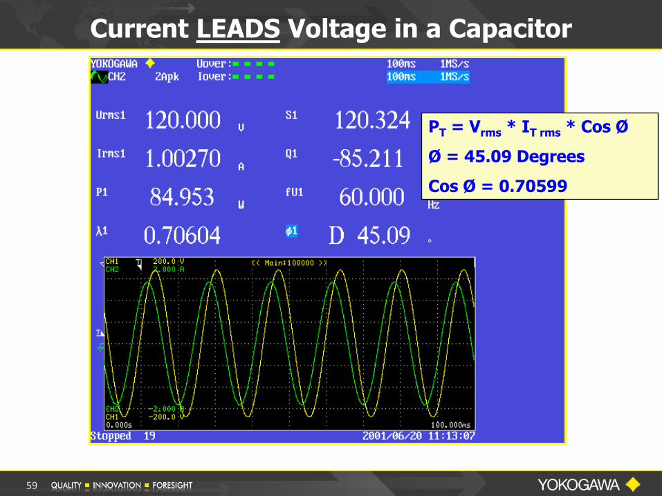
Current LEADS Voltage in a Capacitor
PT = Vrms * IT rms * Cos Ø
Ø = 45.09 Degrees
Cos Ø = 0.70599
59

Inductive Load
AC Motor
Current LAGS Voltage in an Inductor
Capacitive Load
Compact Florescent Lamp
Current LEADS Voltage in a Capacitor
Real World Examples
60
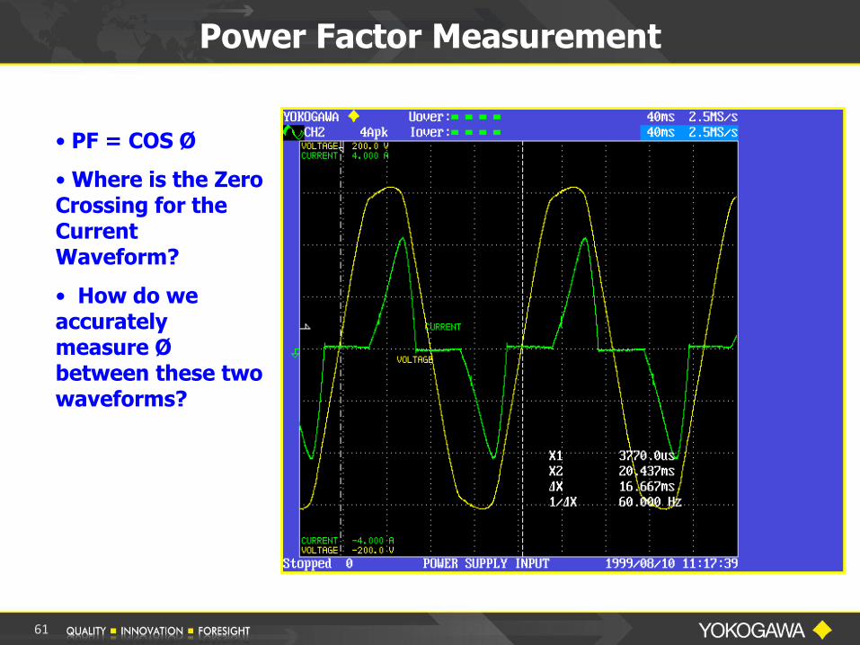
Power Factor Measurement
• PF = COS Ø
• Where is the Zero Crossing for the Current Waveform?
• How do we accurately measure Ø between these two waveforms?
61

Power Factor Measurement
For SINE WAVES ONLY
PF = Cos Ø
This is defined as the DISPLACEMENT Power Factor
---------------------------------------------------------
For All Waveforms
PF = W/VA
This is defined as TRUE Power Factor
62
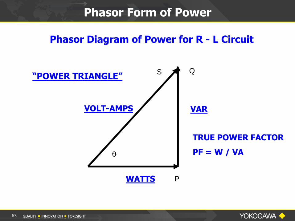
Phasor Form of Power
P
Q S
0
Phasor Diagram of Power for R - L Circuit
VAR
WATTS
VOLT-AMPS
TRUE POWER FACTOR
PF = W / VA
“POWER TRIANGLE”
63

Power Factor Measurement
True Power Factor
PF = W / VA
PF = 87.193/113.753
PF = 0.76651
Power Supply Input
64
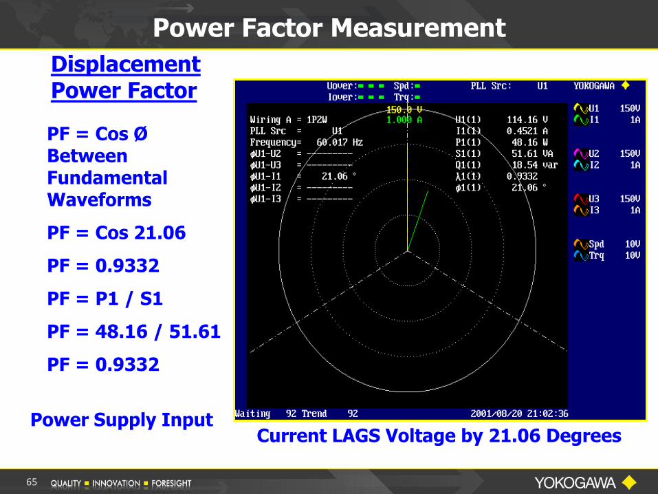
Power Factor Measurement
Displacement Power Factor
Power Supply Input
PF = Cos Ø Between Fundamental Waveforms
PF = Cos 21.06
PF = 0.9332
PF = P1 / S1
PF = 48.16 / 51.61
PF = 0.9332
Current LAGS Voltage by 21.06 Degrees
65

Power Factor on 3-Phase System
3-Phase 4-Wire System
PFTotal = W / VA
PFTotal = ( W1 + W2 + W3 ) / ( VA1 + VA2 + VA3 )
66
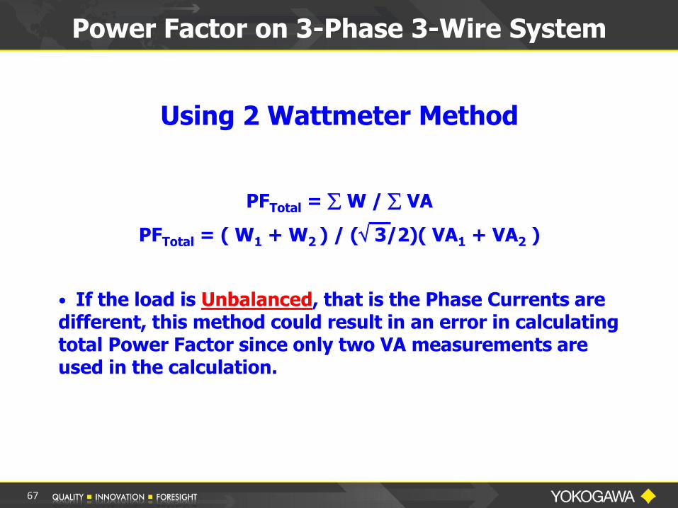
Power Factor on 3-Phase 3-Wire System
Using 2 Wattmeter Method
PFTotal = W / VA
PFTotal = ( W1 + W2 ) / ( 3/2)( VA1 + VA2 )
• If the load is Unbalanced, that is the Phase Currents are different, this method could result in an error in calculating total Power Factor since only two VA measurements are used in the calculation.
67
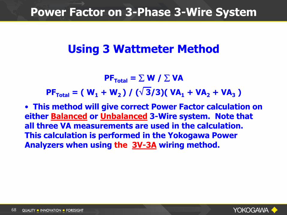
Power Factor on 3-Phase 3-Wire System
Using 3 Wattmeter Method
PFTotal = W / VA
PFTotal = ( W1 + W2 ) / ( 3/3)( VA1 + VA2 + VA3 )
• This method will give correct Power Factor calculation on either Balanced or Unbalanced 3-Wire system. Note that all three VA measurements are used in the calculation. This calculation is performed in the Yokogawa Power Analyzers when using the 3V-3A wiring method.
68
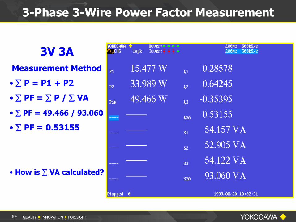
3-Phase 3-Wire Power Factor Measurement
3V 3A
Measurement Method
• P = P1 + P2
• PF = P / VA
• PF = 49.466 / 93.060
• PF = 0.53155
• How is VA calculated?
69
POWER MEASUREMENT APPLICATIONS
70
Standby Power
Energy Star®
&
IEC62301 Testing
71
International Standard IEC62301
Household Electrical Appliances –
Measurement of Standby Power
Hardware and Software
Measurement Solution
Overview
72

Scope
This International Standard specifies methods
of measurement of electrical power
consumption in Standby Mode. It is
applicable to mains powered electrical
household appliances.
The objective of this standard is to provide a
standard method of test to determine the
power consumption of a range of appliances
and equipment in standby mode.
73
Terms and Definitions
The Standard also references Twenty Five
(25) IEC Standards for various Household
electrical appliances.
These standards define the various test
parameters with the limits for items such as
THD, Power and other items for the
appropriate product.
In the US and North America, the Energy
Star® standard is typically used for the testing
limits.
74
75
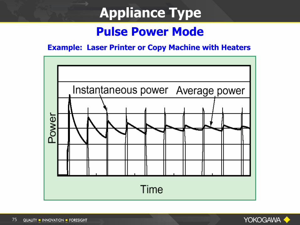
Appliance Type
Pulse Power Mode
Example: Laser Printer or Copy Machine with Heaters
Terms and Definitions
Yokogawa’s Standby Power Measurement:
• Energy divided by Time > Watt-Hour/Time.
• This is the Average Active Power
measurement mode.
• This is the preferred method as it works on
both steady and fluctuating power sources
and is the most accurate method.
• Yokogawa pioneered this method with the
Model WT200 introduced in 2000.
76

OTHER APPLICATIONS
77
78
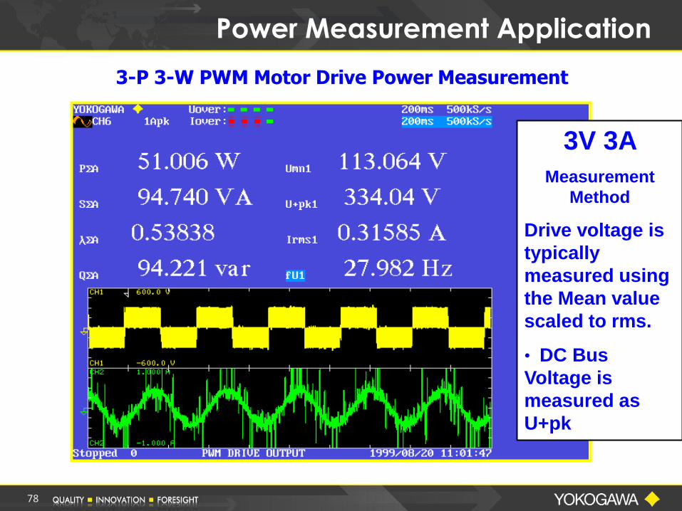
Power Measurement Application
3-P 3-W PWM Motor Drive Power Measurement
3V 3A
Measurement
Method
Drive voltage is
typically
measured using
the Mean value
scaled to rms.
• DC Bus
Voltage is
measured as
U+pk

79
Device Efficiency Measurement
Device Efficiency is Calculated as Output Power Divided by Input Power
Usually expressed as a percentage
Use Two Power Meters to Measure the Input and Output Power
Calculate the Efficiency from the readings of the two Power Meters
Problem – Input and Output Readings may not be made Simultaneously. Possible error due to Time Skew
Use a Multi-Element Power Analyzer to Measure Input and Output Power
Calculate the Efficiency in a Single Power Analyzer
Eliminates any Error due to Time Skew of Measurements

80
Device Efficiency Measurements
Device
Efficiency:
Output P
Input P
Power Analyzer Setup Menu
81
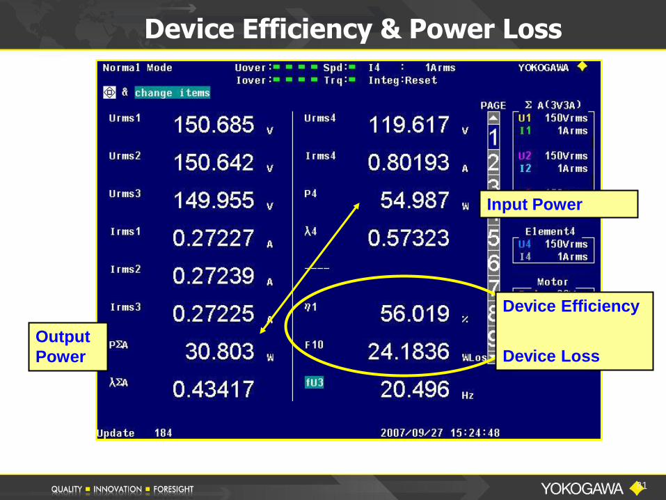
Device Efficiency & Power Loss
Device Efficiency
Device Loss
Input Power
Output
Power

82
Power Measurement Application
Device Start Up Analysis
Device Voltage
Device Current
Cycle-by-Cycle
Start Up Power
PART III
BASIC POWER MEASUREMENTS using a
DIGITAL OSCILLOSCOPE
83

84
Power Analysis with a DSO
Why use a Digital Oscilloscope for Electrical Power Measurements?
• We have a “Comfort Level” using an Oscilloscope
• Dedicated Probes & Ease of Connections
• Power Analysis Math Capabilities
• High-frequency Bandwidth
• Waveform Display & Analysis
• Harmonic Analysis to IEC Standards
Special Note:
When using an oscilloscope, AC Power is not just connecting a voltage probe to Ch1 and a current probe to Ch2 and then multiplying Ch1 x Ch2. This will give an AC measurement of VA, not AC Watts.
Measurement of Power
85
Measurement of Power
Remember - AC Power Measurement
Active Power:
Watts P = Vrms x Arms x PF
Also sometimes referred to as True Power or Real Power
Apparent Power:
Volt-Amps S = Vrms x Arms
86

Measurement of Power
Yokogawa Digital Power Scopes use the following method to calculate power:
Pavg = 1/T 0 v(t) * I (t) dt
Taking advantage of digitizing techniques, the
INSTANTANEOUS VOLTAGE is multiplied by the INSTANTANEOUS CURRENT and then INTEGRATED over some time period.
T
87
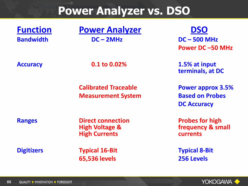
Power Analyzer vs. DSO
Function Power Analyzer DSO Bandwidth DC – 2MHz DC – 500 MHz Power DC –50 MHz Accuracy 0.1 to 0.02% 1.5% at input
terminals, at DC Calibrated Traceable Power approx 3.5% Measurement System Based on Probes DC Accuracy Ranges Direct connection Probes for high
High Voltage & frequency & small High Currents currents
Digitizers Typical 16-Bit Typical 8-Bit 65,536 levels 256 Levels
88

Skew = Propagation Delay Difference
Current clamp
e.g. 30 A, 100 MHz model 701932
Differential probe
e.g. 1400 V, 100 MHz
model 700924
Successful de-skew!
Deskew Source - model 701936
Auto Deskew function
Measurement Challenge: SKEW
Synchronous
reference signal for
voltage and current
Current Voltage
89

90
Signal edges are aligned
Deskew Calibration
• Signal source used for adjusting the skew between a voltage probe and a current probe.
- Many different kinds of probes can be used for power measurements. Each probe has a different signal path length. - Signal source generates time-coincident voltage and current signals. This allows you to adjust for skew between voltage and current probes.

BEFORE DE-SKEW
91

AFTER DE-SKEW
92
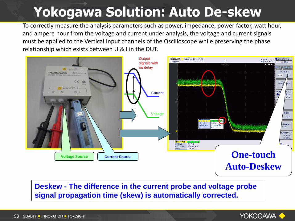
Deskew - The difference in the current probe and voltage probe
signal propagation time (skew) is automatically corrected.
Yokogawa Solution: Auto De-skew To correctly measure the analysis parameters such as power, impedance, power factor, watt hour, and ampere hour from the voltage and current under analysis, the voltage and current signals must be applied to the Vertical Input channels of the Oscilloscope while preserving the phase relationship which exists between U & I in the DUT.
One-touch
Auto-Deskew
Voltage Source Current Source
Current
Voltage
Output
signals with
no delay
93
94
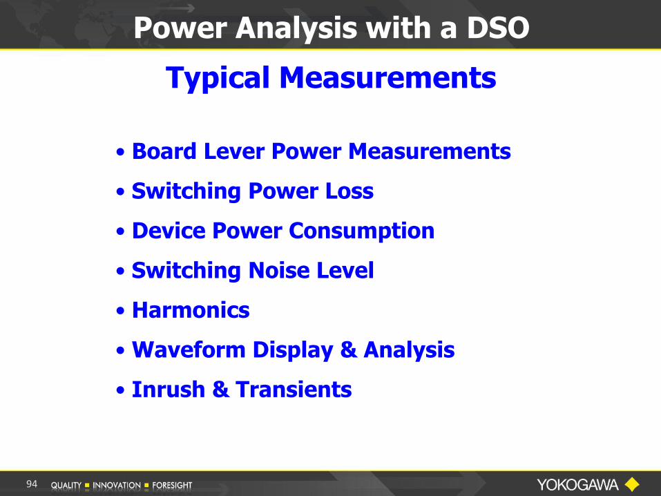
Power Analysis with a DSO
Typical Measurements
• Board Lever Power Measurements
• Switching Power Loss
• Device Power Consumption
• Switching Noise Level
• Harmonics
• Waveform Display & Analysis
• Inrush & Transients

95
Power Supply Input with Power Analyzer

Power Supply Input with DSO
96

97
Power Supply Input Summary
Measurement Comparison
Measurement
Item
Power
Analyzer
Power
DSO
Voltage RMS 118.28 V 117.27 V
Current RMS 1.3323 A 1.3321 A
Watts 97.54 W 96.49 W
Power Factor 0.619 0.617

98
PWM Inverter Output with Power Analyzer
99
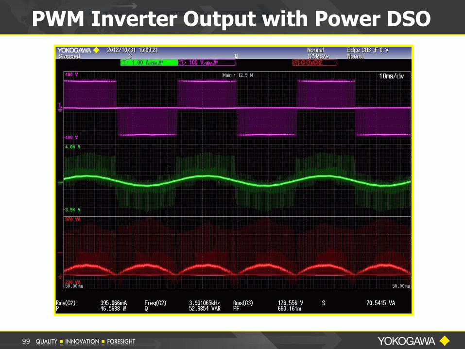
PWM Inverter Output with Power DSO
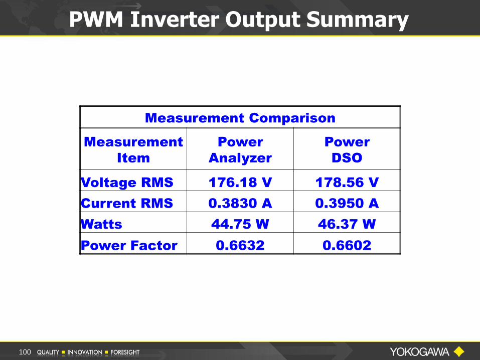
100
Measurement Comparison
Measurement
Item
Power
Analyzer
Power
DSO
Voltage RMS 176.18 V 178.56 V
Current RMS 0.3830 A 0.3950 A
Watts 44.75 W 46.37 W
Power Factor 0.6632 0.6602
PWM Inverter Output Summary

DSO Power Calculation
101

• Power Measurements with a DSO – Oscilloscope – Options – power analysis, probe power – Probes
• Differential Voltage Probe • Current probe • High Voltage Probe
– Other • Isolation line-transformer for non-isolated designs
(safety). • Deskew Device
What You Will Need
102

Yokogawa offers the Most Complete Line of Power Measurement Products to meet the customers Application and Budget.
Product, Application and Software support provided from a network of Field Sales Reps, Factory Regional Sales Managers and Factory Support Engineers.
NIST Traceable Calibration provided by Factory Trained technicians in Newnan, GA.
Yokogawa’s Power Measuring Solutions
103

Yokogawa’s Power Measuring Solutions
Precision Power Analyzers
104
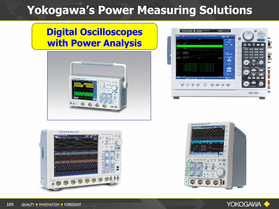
Digital Oscilloscopes with Power Analysis
Yokogawa’s Power Measuring Solutions
105
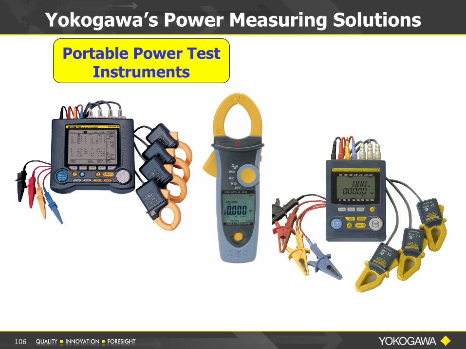
Portable Power Test Instruments
Yokogawa’s Power Measuring Solutions
106
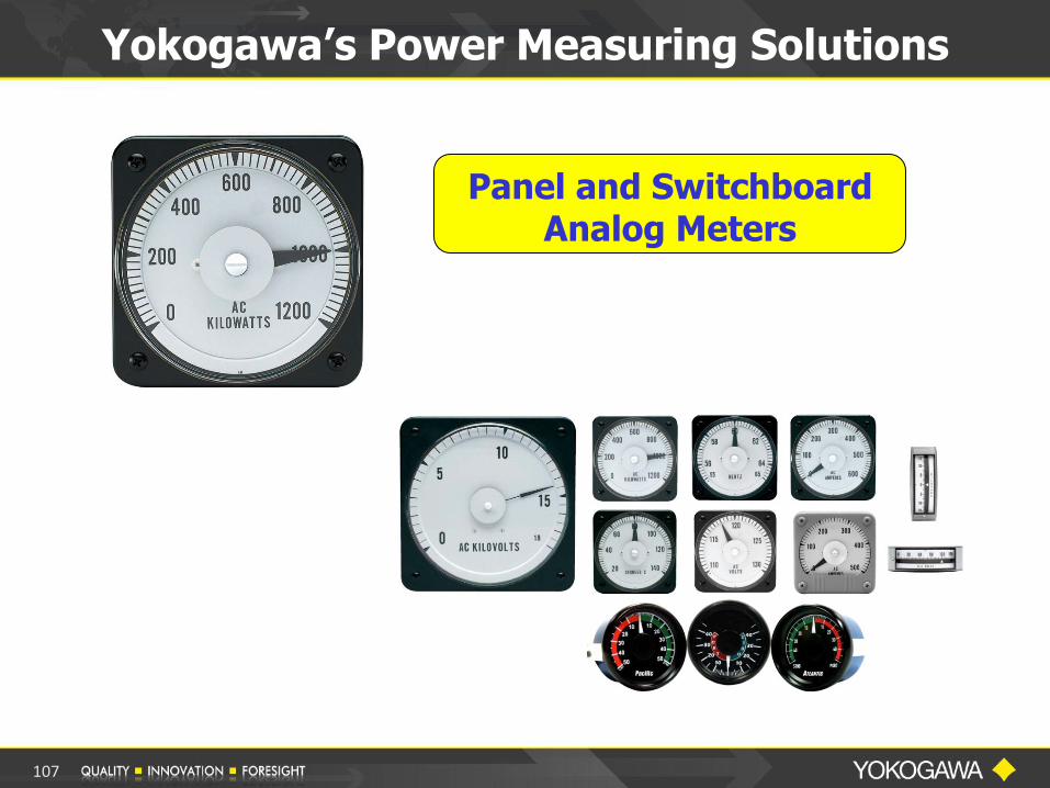
Panel and Switchboard Analog Meters
Yokogawa’s Power Measuring Solutions
107

Power Transducers
Yokogawa’s Power Measuring Solutions
108
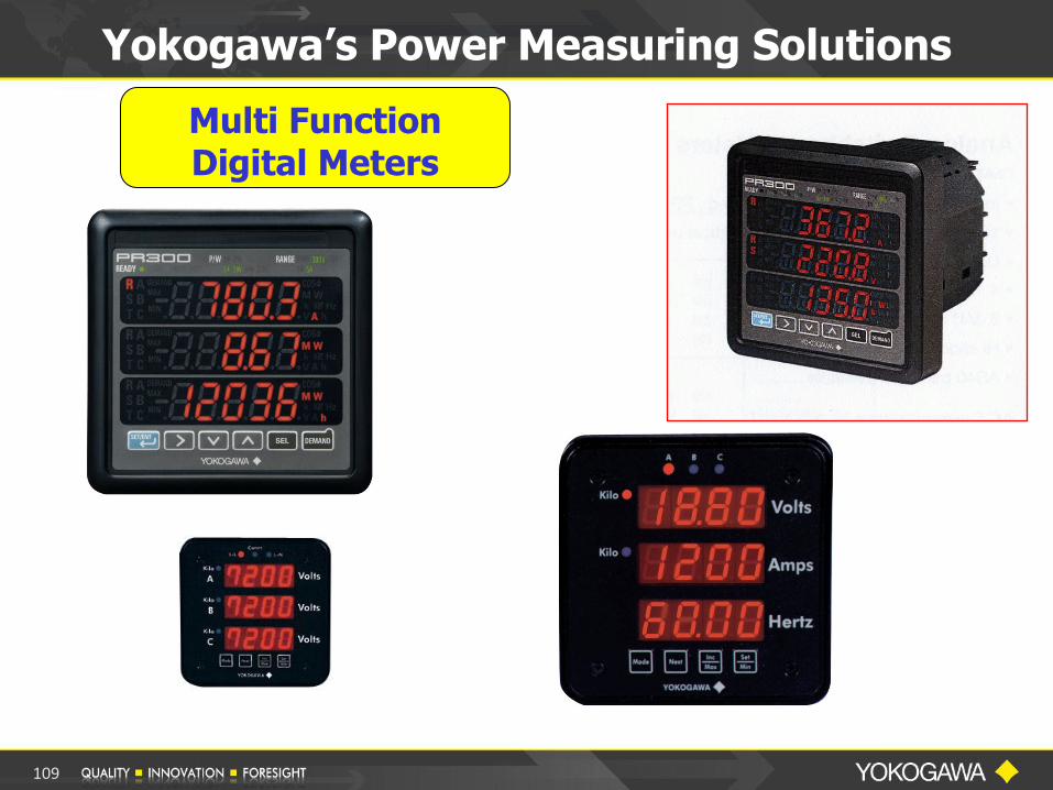
Multi Function Digital Meters
Yokogawa’s Power Measuring Solutions
109

Portable Instruments
Yokogawa’s Power Measuring Solutions
110
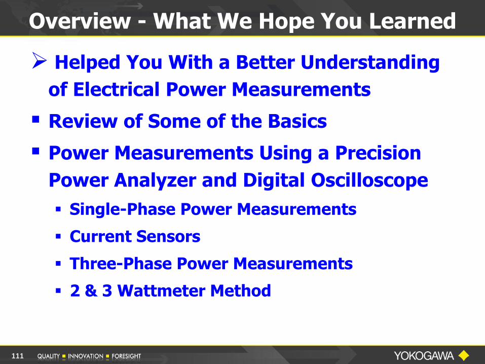
Overview - What We Hope You Learned
Helped You With a Better Understanding
of Electrical Power Measurements
Review of Some of the Basics
Power Measurements Using a Precision
Power Analyzer and Digital Oscilloscope
Single-Phase Power Measurements
Current Sensors
Three-Phase Power Measurements
2 & 3 Wattmeter Method
111
Part II: Power Factor Measurements
Displacement Power Factor
True Power Factor
Power Factor Measurements in Single-
Phase & Three-Phase Circuits
Practical Power Factor Measurement
Applications
Overview - What We Hope You Learned
112

Part III: Power Measurements using a
Digital Oscilloscope
How to properly use a Digital Oscilloscope to
make Electrical Power Measurements
De Skew Operation Measurement Examples on a Power Supply
Input and a PWM Inverter Output Measurement Comparison between the DSO
and a Power Analyzer
Answer your questions concerning
Electrical Power Measurements
113
Overview - What We Hope You Learned

Thank You
For
Attending
114

Join Us for Future Web Seminars
Visit our Web Site
tmi.yokogawa.com
Go to > Technical Library
> Webinars On-Demand
115

Yokogawa Corp of America
Test & Measurement Div.
2 Dart Rd. Newnan, GA 30265
tmi.yokogawa.com
Tel: 1-800-888-6400
Bill Gatheridge
Product Manager
Ext 5454
116