functions of bedding and filling materials - ikt · functions of bedding and filling materials...
TRANSCRIPT

Sewer construction
Functions of bedding and filling materials
Installation of the layer of coarse grain 100-150 mm, from [2]
Bedding and filling materials in the sewage and pipeline construction should substan-tially contribute to structural stability of the building. In measures for rainwater retention and vegetation design, filling materials with special characteristics are used. Experience from research and pilot projects with these application cases, pos-sible conflicts as well as new bedding and filling materials now show perspectives how different utilizations and material functions in the pipeline trench can be mutually supplemented.
IntroductionBedding and filling materials are used in the sewage and pipeline construction in order to sub-stantially contribute to the structural stability of the underground building and where appropriate to the building on the street, as part of the pipe/ground structural support system. In general, the characteristics of filling materials in the city structural formation with view of water economic aspects and the arrangement of tree locations are of greater importance. Under congested con-ditions, conflicts can also occur in the ground, for example, from the interaction of tree roots with underground sewage system and pipelines.
With this background, the question is, which role does the bedding and filling materials as a building element of the classic pipeline trench play individually, which innovative materials in this context are researched to-date and used in practice, and which perspectives arise for com-bined requirements and utilizations of the used materials in the pipeline trench. The following versions give an overview based on the project experience at the IKT - Institute for Underground Infrastructure, Gelsenkirchen.
City planningIn city planning, the use of bed-ding and filling materials, especially in the course of decentralised storage and infiltration of rainwater is becoming important. Corresponding measures influ-ence the following, among other things (cf. [1]):
the drain dynamics within and beneath a settlement zone,
the new ground water formation, the municipal water and its ecological condition
Just in densely populated cities with high seal-ing degrees and intensive utilization of the surfaces and underground space, appropriate measures can only be implemented in isolation rarely or not at all. It is therefore opportune to combine possible zones for the storage and infil-tration of rainwater with elements of vege tation planning and especially with planting pits of trees in this case.
In Stockholm, for example, trees planting pits are used for rainwater farming, and tree irriga-tion occurs simultaneously [2]. The planting pits were executed there with an expanded rhizo-sphere. In the specific case, the rhizosphere was constructed graduated and has an entire height of ca. 1.0 m. The lower layer consists of broken material - grain sizes 100 to 150 mm - with a layer thickness of 600 mm.
Above, a layer approx. 180 mm strong with broken material of grain size 63 to 90 mm is incorporated. In both of these, a small share of fine earth is flushed on layer that is rich in coarse pores, especially to improve the water
retention. In the next step, a partition fleece is put in place and crushed rock is poured to make a formation for laying the sidewalk slabs, pav-ing stones, or asphalt. All layers are respectively compacted. The provision of rhizosphere with air and water occurs through a special ventila-tion and irrigation component that penetrates a depth of approx. 80 cm into the rhizosphere. A street gully is placed on the stainless steel element that forms the termination to the pave-ment or asphalt surface.
Figure 1 and 2 give an impression of the situa-tion on the spot: After conclusion of the project, the surface will be restored. The rhizosphere cre-ated underground is then no longer recognizable and the surface can be used without restrictions [2]. The result must ensure that actual irrigation is provided without rewetting risks and oxygen deficiency for the plants. In strongly compacted grounds, rainwater is transmitted away where appropriate.
Tree roots and pipelinesThe conditions of life of city trees were inves-tigated comprehensively in the past decades. The volume of root system must stand in a well-balanced relationship to the volume of the crowns. A rhizosphere that is too small generally
31 IKT
Sewer construction
has diminished growth of aboveground parts of the tree as consequence [3].
The pore space in the ground has essential influ-ence on root growth. Roots serve for the up-take of nutrients and water from the soil. They should in addition anchor the plant in the ground. Unhindered root growth occurs in large pores. At the same time, it is assumed that roots can penetrate in pores of diameters greater than 0.2 to 0.4 mm [4], [5]. Fine pores are occupied by root hairs. In order that the organism can further cover its need for nutrient and water over its entire life, also the root system grows further and steadily opens itself new ground space. At the same time, roots, like all plant parts, depend on functioning respiration (oxidation) carbohy-drate rich connections for energy generation. Necessary oxygen is found in natural soil struc-ture in soil air and can be absorbed by roots. Low oxygen contents in soil air are described as a trigger for growth depression ([6], [7].
From vegetation point of view, especially requirements are made on substrates for plant-ing of trees with respect to (cf. [8], [9]):
grain size distribution, for example predomi-nantly sand as well as gravel/crushed rock, supplemented with silty and clayish shares
soil air-/soil water household, for example, with respect to water permeability kf and an entire pore volumes greater than 35%
soil chemistry, for example, a share of organic substance smaller than 2-4 %-mass
Load bearing capacity, for example as demands on the deformation modulus and proctor density in vegetation layers.
These requirements make it clear that with use of classic bedding and filling materials of the sewage and subsurface pipeline construction, for example gravel-sand-mixture, frequently unconsciously an especially ground that can be penetrated well by roots is created, which
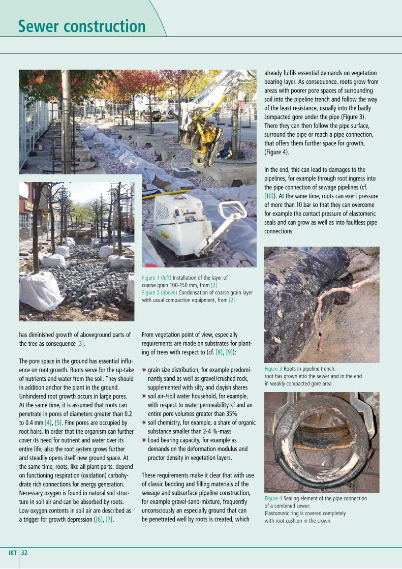
already fulfils essential demands on vegetation bearing layer. As consequence, roots grow from areas with poorer pore spaces of surrounding soil into the pipeline trench and follow the way of the least resistance, usually into the badly compacted gore under the pipe (Figure 3). There they can then follow the pipe surface, surround the pipe or reach a pipe connection, that offers them further space for growth, (Figure 4).
In the end, this can lead to damages to the pipelines, for example through root ingress into the pipe connection of sewage pipelines (cf. [10]). At the same time, roots can exert pressure of more than 10 bar so that they can overcome for example the contact pressure of elastomeric seals and can grow as well as into faultless pipe connections.
Figure 1 (left) Installation of the layer of coarse grain 100-150 mm, from [2]Figure 2 (above) Condensation of coarse grain layer with usual compaction equipment, from [2]
Figure 3 Roots in pipeline trench: root has grown into the sewer and in the end in weakly compacted gore area
Figure 4 Sealing element of the pipe connection of a combined sewer:Elastomeric ring is covered completely with root cushion in the crown
32IKT

In the framework of the research project [10], the causes for root ingress in sewage pipelines and channels were investigated comprehensively. It was confirmed that especially in anthropogeni-cally influenced city soil, different soil kinds are found in small space whereby the soil charac-teristics differently influence root growth. With view of the soil in the pipeline trench, a pore room especially too small for roots leads to a handicap and/or prevention of root growth and can be used therefore for the protection from roots (Figure 5). The use filling materials with poor pores is conceivable here, which can be brought in place both as flowable material and as a material with bentonite content and/or bulk material capable of swelling. Conversely, soil with sufficient and well-ventilated pore room is considered as plant substrate that is taken over by roots as habitat.
These contexts on the interaction behaviour between roots and different substrates are for example very clear in tests on plant boxes [11]. Roots made of poplars (Populus spec.) grow there in a plant substrate in the surrounding of an incorporated bentonite body, i.e. plastic material with high clay content. The roots grew on the boundary area - substrate/bentonite - on the substrate side along the bentonite. Individual roots grew nonetheless also into the bentonite.
Here it is assumed that swelling and shrinkage cracks in the bentonite were filled out by roots.
When tuning lacks between the requirements of civil engineering and the vegetation plan-ning, not only pipelines but also tree roots can be damaged disproportionately. As a preventive measure, it is therefore recommended in [12], [13] especially to provide a root curtain before the start of the construction process.
According to [13] a ditch is excavated manually in approx. 0.3 m distance from the future building project, corresponding to the root penetration
depth. On the side towards the trench, all roots are cut off and the interfaces treated. Posts are installed on the trench wall towards the con-struction pit, then non-galvanised wire mesh is nailed on the posts and a bale cloth made of Jute is fixed on the wire. The ditch is then filled with suitable substrate. Here the direct ques-tion is to what extent by this action is just the ingrowth of roots into the pipeline trench just facilitated. Certainly, this depends again on the characteristics of used bedding and filling mate-rials. Which role do these materials as building elements of the structural support system pipe/soil play, is therefore supposed to be clarified as follows.
Structural support system pipe/soilIf sewage pipes are incorporated in open meth-od of construction, the so-emerging structural support system pipe/soil can be described for circular round pipes according to Figure 7. The cross-section view corresponds to that for earth-laid sewers and pipelines according to [14] usual assumption of uniform bedding- and deforma-tion characteristics in longitudinal direction. The interactions between pipe, imbedding, trench filling, and surrounding soil can then be attri-buted to five-model assumption:
1. The theory of silo effect for soil load calcula-tion in pipe crown height goes back to the investigations of Janssen [15], Terzaghi [16], and Marstone [17]. According to this model assumption, slide and/or shear surfaces form on the trench walls similarly to the area between bulk goods and silo walls. The result-ing friction forces occurring in these shear surfaces due to settling increase or diminish the cantilever wall. The type of trench support and where appropriate the evolving „support track“ gains special importance [18]. In addi-tion, both trench walls must remain in place for activation by frictional forces and they may not be removed during subsequent mate-rial excavation of a neighbouring construction trench.
2. In case of good compaction of lateral soil next to the pipe, vertical loading by the pipe and lateral soil are carried together. The vertical load distribution over the pipe crown then depends on the rigidity of the soil in the
Figure 6 Poplar roots and bentonite body in plant box – roots grow along the boundary area to the bentonite as well as in the bentonite body in isolated cases, from [11]
Figure 5 Spreading of roots is influenced by soil characteristics (principle sketch)
Filling material corresponds to favourable tree substrate, for example pore-room rich, gravel-sandy-silty with little organic shares
Filling material corresponds to unfavourable tree substrate, for example poor in pore-room, strongly clayish, little air and water permeability
33 IKT

Sewer construction
relationship to pipe stiffness. If the pipe is stiffer than the soil, the loads concentrate on the pipe. If the soil is stiffer than the pipe, the soil bears the greatest share of the loads. This model concept has found also input into Ger-man calculation practice (cf. [19], [14]).
3. The support stresses under the pipe sole are determined generally under the approach of a defined support angle (cf. [20], [14], [21]). The constructive erection of pipe bearing, i.e. especially compaction of the gore area under the pipe, influences structural stability of entire system.
4. Horizontal earth loads also already act on a stiff pipe, which can be applied approximately at the height of the so-called of „soil pressure at rest“ (cf. [14]).
5. In larger cross-sectional deformations of flex-ible pipes (e.g. plastic pipes), the soil next to the pipe can unfold further supporting effect. The vertical deflection then yields a horizontal diameter enlargement through which the pipe in the soil activates a horizontal bedding reaction pressure. In addition, this approach has found entry into the calculation concept according to [14].
Especially the soil characteristics in the area of the pipeline zone influences substantially load-bearing capacity, settling behaviour, usage capacity, operational reliability, and utilization duration of underground sewage and pipelines [23]. In the pipeline zone, according to [24] granular, unbound construction materials should be used. Even hydraulically bound construction materials are acceptable as far as they cor-respond with the planning requirements. As granular, unbound construction materials, for example sand-gravel-mixtures with graduated graining and negligible binding shares (<3%) are considered as suitable according to [24], Supple-ment B, Table B4. For the application of industri-ally produced rock classifications and recycling (RC)-construction materials, its suitability due to mechanical soil viewpoint and environmental friendliness have to be especially proved.
According to [23], Chap. 12.4.2 the following applies specifically:„The compaction degree in the pipeline zone and main filling must be tested. Acceptance cri-teria are soil characteristic values based on soil characteristic values or the requirements of ZTVE StB 94, Edition 97.“
In addition, a concrete bedding as a part and full casing is listed in [23], Chap. 7, implementation possibility, when locationally different soil types, changing water levels, a strongly inclined trench sole or rock exist.
If the so described structural support system pipe/soil is supposed to be produced reliably and cost-effectively also under congested space conditions, then the direct question posed calls for procedure and material optimization possibilities, especially also with view to bedding and filling materials.
Material developmentsFurther development of bedding and filling materials has as construction goal, to reduce the working space necessary for the execution of uniformly well-compacted bedding of the sewer and at the same time to ensure the quality of the hardly accessible gore area. As examples for such developments, the following should be cited: Flowable self-compacting bedding and fill-ing materials as well as bedding cushions made of expandable polystyrene (EPS).
Flowable self-compacting filling materialsThese filling materials are also cited in [23] as a special procedure for the manufacture of pipeline zone and main filling with the follow-ing components: Classified non-binding mineral material or also binding material (pending trench excavation material, soil derived from elsewhere or recycling material), plastifying and stabilising additives, cement, water and where appropriate pores or foaming agent.
Figure 7 Pipe/soil in open method of construction, model assumptions (representation of the spring model of bedding reactions, from [14])
Figure 8 Installation of flowable self-compacting filling materials in narrow trench width
34IKT

According to [23], Chap. 7 „its suitability in a specific application case must be examined under the consideration of the interaction with naturally available soil. In this regard it is recom-mended to consult a specialised expert.“
Flowable self-compacting bedding- and filling materials are used especially in order to optimally fill the critical support area optimally even under congested space conditions and to obtain uniform bedding in the entire pipeline zone (Figure 8). Moreover, through the excavation work, cavities that emerge can be filled with the excavated material in order to avoid retroactive settling.
With this background, extensive large tests were carried out in the IKT, which in the end con-firmed positive effect of flowable bedding and filling materials on the contact stresses between soil and pipe [25]. Tests were conducted in the scale 1:1, in which the complete loading history of a pipe was imitated from the installation via dismantling of construction elements up to traf-fic loads, ground water variations, and mountain declines. Clearly more uniform contact stress dis-tributions in the support area, i.e. in the left and right gore areas between pipe and soil (Figure 9) in the result in contrast to the utilised bulk goods in the same test setup.
Experiences from accompanying in-situ-meas-ures in the German cities Dusseldorf (cf. [26]) and Gelsenkirchen showed on the other hand also, which special risks are to be observed in the construction practice in the use of flowable bedding- and filling materials. On the one hand, the buoyancy forces emerging on the pipe must be absorbed. This is usually connected with high technical expense, e.g. through gradual filling of the pipeline zone or by using appropriate hold-ing structures (Figure 10).
Figure 9 Contact stresses in the pipe support between soil and pipe: Installation condition (left), after pulling the bulkhead (middle) and under the load (right) - [25] bulk material: Mineral mixture, EKA bed, and gravel sand; flowable: Weimarer soil mortar and RSS©-fluidised soil
Figure 10 Examples for buoyancy safeguard: Wooden beam construction (above) and RSS© system (below)
35 IKT

Sewer construction
Figure 11 Practical application of bedding cushions: laying (top left), cutting to size on site (bottom left), complete encapsulation as a variant (right)
EPS. Different variants are offered here, which differ essentially from one another through their density. In the project, an EPS 35, i.e. expand-able polystyrene with a density of 35 kg/m3, proved suitable for use as a pipe bedding in the sewage and pipeline construction. The density of the material can be controlled by simple measuring and weighing and a static calculation according to [14] is possible (cf. [27] in proven material behaviour and simple laying procedure. In addition, it should be noted that the cushion dimensions must be adapted especially to the respective outside diameter of used pipes. In addition, here, a random sample-like inspection is recommended.
PerspectivesThe above example on city planning clarified already that by the selection of bedding and filling materials different utilization methods can be addressed simultaneously. For instance, materials with larger pore space promote both possibilities for the decentralised rainwater farm-ing and for the rhizosphere formation as well. In addition, filling materials rich in pore space are used also in the sewer and pipeline construction owing to soil mechanics reasons, as they find application to vegetation bearing layers. Supple-
mentary technical measures in the underground, e.g. the formation of a root curtain before trench excavation, can increase the range of consid-eration. Here the question is now whether the knowledge of these different utilizations also offers new perspectives for civil engineering solutions.
Based on the experiences represented in this text Figure 12 shows a suggestion for multifunc-tional formation of the pipeline trench. Using different bedding- and filling materials, the represented trench zones S, D, H, N, can then be attributed to different utilizations or functions. Examples are as follows:
N – Utilisation: Usually this area is dimensioned for the load transfer from road surface. At the same time, it cannot be ruled out that pore spaces of this area also allow root growth and unfold drainage effect. A scheduled utilization can clearly emphasize these connections and make the deliberate. This applies generally to the scheduled formation of a vegetation layer on which a structure can be built, as they are also recognised for other areas (cf. [9]). Nonetheless, it should also be considered that during later measures on the underground pipeline in open method of construction, this area and thus the root system must be disturbed (again). In addi-tion, it should also be questioned whether in the case of vegetation utilization where appropriate special measures are to be planned for construc-tion above the ground.
On the other hand, in a subdivision into several construction sections, these must be partitioned and/or sealed in an appropriate manner in order to prevent uncontrolled spreading of the mate-rial. In addition, the flowing capacity of the material can also be connected with first of all unexpected quantity scope, for example, if cavi-ties behind the construction elements are filled or water leaks into the surrounding soil.
In the scope of the quality assurance of the mate-rial characteristics, besides the flowing capacity in the installed condition, also demands on the strength, solubility, and permeability of the cured material should be formulated. The strength development and the deformation occurring dur-ing fracture should be verified in dependence on the curing time over a longer period. The long-term solubility, especially for later connection of lateral inflows, for example can be verified in modified pile-driving test (cf. [25], „spade ram“) in order to grasp also the influence of the grain distribution on the penetration behaviour of dismantling tools. If special demands were made on the permeability and/or impermeability of the material, then samples should be taken for verifi-cation in construction accompanying manner.
Bedding cushion made of EPSThese bedding cushions are used in order to exe-cute the critical support area in earth laid sewage systems and pipelines optimally and if necessary to be able to lay even pipelines one above the other. In a research project [27], the suitability of such bedding cushions in laboratory tests and con-struction site application was investigated. Espe-cially the practical applications on the construction site underlined the advantages of the system with respect to handling and installation speed (cf. Pictures 11). In addition, also tests stretches were in the meanwhile executed with EPS full casing of plastic pipes and a combination with the use of flowable filling materials discussed [28].
Usage risks exist especially with respect to the resistance of the EPS against aggressive soil ingredients as well as gasoline and oil types. In groundwater, the buoyancy of the bedding cush-ions must be considered in the calculation and dimensioning of the pipes and trenches.
In the framework of quality assurance attention is to be paid especially to the used quality of the
36IKT

D – Cover layer: The cover layer jointly with the lateral filling S and the internal shearing forces in the utilisation zone N contribute to the load distribution within the pipeline zone. By using particularly materials with less pores, a layer that accordingly repels root growth can formed here. For example, if flowable, castable materials are used, also the civil engineering requirements according to [24] can be fulfilled.
S – Lateral filling: The lateral filling serves substantially for the transfer of vertical loads, especially in load distribution in this area. Well compressible materials are to be used. In the sense of root protection, it is convenient - similarly to the cover layer - also to use self-compacting materials with hardly any pores. If a rich pore-space material is used, utilization as drainage space is also considerable.
H – Cover zone: The cover zone can serve directly for pipe protection during the installation (cf. EPS- or concrete full casing). If EPS is used, also in rigid pipes, a deformation capable overall, system occurs, which can avoid vertical loads (cf. Deformation layer according to [14]). The cover zone, where appropriate, also jointly with the zones S and D, can be filled with poor pore space material. In water protection areas, strong impervious material (cf. „mineral mixture“ in [25]) can also serve for double exfiltration pro-tection, similar to double wall pipes. The capacity of EPS for thermal insulation additionally opens a special perspective for sewage waste-heat utilization. A possibly high-energy gain could be secured in the area behind heat inputs.
ConclusionsManifold requirements are put especially under-ground in the urban area. This concerns also questions of the water economy, vegetation planning, and other utilizations besides the constructional load-bearing capacity (e.g. waste water/soil heat). The trenches produced in open method of construction in the course of sewer and pipeline construction offer the chance to address these manifold utilizations jointly by targeted use of innovative bedding and filling materials. Advantages arise with view of the following points:
Economic viability: Construction costs can be reduced through smaller trench widths and
faster construction processes and risks from root growth can be diminished through targeted use of materials with hardly any pores. Cost saving potentials would offer also a contractual link of several costs carriers, for example for green and underground infrastructure.
Quality of life: A reliable supply and disposal with simultaneously green and attractive city-scape offers good prerequisites for high quality of life. Planning freedom of action is therefore sought after also under congested space condi-tions. These are convenient for example if in the upper pipeline trench area – where roots mostly already penetrate today - vegetation layers are planned, on which construction is possible. Simultaneously, the direct surrounding of the underground infrastructure is then to be pro-tected by root-repelling filling zones so that root damages to the pipelines are diminished.
Sustainability: A sustainable development of the cities requires methodical approach. This relates also to the underground with its manifold utilization. The present competition about under-ground space, for example expressed by the demand for minimum distances or barrier zones, massively limits the adaptability. Climate varia-
tions and demographic developments however demand flexibility and early identification and planning of action options. Here, multifunctional utilisations of bedding and filling materials for nearly complete coverage of pipeline trenches should gain importance.
Authors:Dr.-Ing. Bert Bosseler, Research Director Dipl.-Ing. Christoph BennerscheidtDipl.-Ing. Martin LiebscherIKT - Institute for Underground infrastructure
Prof. Dr. Thomas Stützel,Ruhr University Bochum
Figure 12 Pipeline trenches with multifunctional trench zonesN – Utilization, D – Cover layer, S – Lateral filling, H – Cover zone
37 IKT

Sewer construction
References[1] Geiger, W.; Dreiseitl, H.: Neue Wege für das
Regenwasser – Handbuch zum Rückhalt und zur Versickerung von Regenwasser in Baugebieten: 2. Aufl. 2001 R. Oldenbourg Verlag GmbH.
[2] Embrén, B.; Bennerscheidt, C.; Stål, Ö.; Schröder, K.: Optimierung von Baumstan-dorten. wwt wasserwirtschaft wassertech-nik, 07-08/2008.
[3] Schröder, K.: Stadtbäume und technische Infrastruktur – Konkurrenz unter Tage. Grünforum, 2005, Band 35, Heft 4, S. 34-38.
[4] Wiersum, L.K.: The relationship of the size and structural rigidity of pores to their penetration by roots, Plant and Soil IX, S. 75-85, 1957.
[5] Bohne, H.; Hartge, K.H.: Auswirkungen der Gefügegeometrie auf den Wuchs von Getreidekeimlingen, Mitt. Dt. Bodenk. Ges. 34: S. 141-144, 1982.
[6] Balder, H.: Die Wurzeln der Stadtbäume, Parey-Verlag, 1998; zitiert in [10].
[7] Scheffer, F.; Schachtschabel, P.: Lehrbuch der Bodenkunde, 14. Aufl., Enke-Verlag, 1998; zitiert in [10].
[8] Schönfeld, P.: Baumpflanzungen in der Stadt: Einsatz von Baumsubstraten und Bauweisen nach FLL und ZTV-Vegra-Mü. FLL-Fachtagung Optimale Standorte sichern Stadtbäumen langes Leben! Standortvor-bereitung und Standortsanierung, Erfurt, 05/2009.
[9] FLL – Forschungsgesellschaft Land-schaftsentwicklung Landschaftsbau e.V.: Empfehlungen für Baumpflanzungen, Teil 2: Standortvorbereitungen für Neupflan-zungen; Pflanzgruben und Wurzelraumer-weiterung, Bauweisen und Substrate. FLL, Bonn, 2004.
[10] Stützel, Th.; Bosseler, B.; Bennerscheidt, C.; Schmiedener, H.: Wurzeleinwuchs in Abwasserleitungen- und -kanäle - Ursachen, Prüfung und Vermeidung. End-bericht zum Forschungsvorhaben, gefördert durch das MUNLV NRW, Lehrstuhl für Spe-zielle Botanik der Ruhr-Universität Bochum und IKT – Institut für Unterirdische Infras-truktur, August 2004.
[11] Stützel, Th.; Bosseler, B.; Bennerscheidt, C.; Schmiedener, H.; Streckenbach, M.: Wurzeleinwuchs in Abwasserleitungen und Kanäle - Ergänzungsvorhaben. End-bericht zum Forschungsvorhaben, gefördert durch das MUNLV NRW, Ruhr-Universität Bochum, Lehrstuhl für Spezielle Botanik und Botanischer Garten und IKT - Institut für Unterirdische Infrastruktur, Bochum Gelsen-kirchen, 06/2007.
[12] DIN 18920: Vegetationstechnik im Land-schaftsbau – Schutz von Bäumen, Pflan-zenbeständen und Vegetationsflächen bei Baumaßnahmen. Beuth Verlag, Berlin, 09/1990.
[13] FGSV – Forschungsgesellschaft für Straßen- und Verkehrswesen, Arbeitsgruppe Straße-nentwurf: RAS-LP 4 Richtlinien für die Anlage von Straßen, Teil Landschaftspflege, Abschnitt 4: Schutz von Bäumen, Vegeta-tionsbeständen und Tieren bei Baumaßnah-men. FGSV, 1999.
[14] ATV-DVWK-A 127: Statische Berechnung von Abwasserkanälen und -leitungen. Regelwerk der DWA Deutsche Vereinigung für Wasserwirtschaft, Abwasser und Abfall e.V., 3. Auflage, 08/2000.
[15] Janssen, H.A.: Versuche über Getreidedruck in Silozellen. Zeitschrift des Vereins deut-scher Ingenieure, Band XXXIX, Nr. 35, S. 1045-1049, 1895.
[16] Terzaghi, K.: Stress distribution in dry sand and in saturated sand above a yielding trap door. First International Conference of Soil Mechanics and Foundation Engineering, Cambridge, 1936.
[17] Marston, A.: Iowa Engineering Experiment Station. Bull. no. 96, 1930.
[18] El Shahid, S.: Zur Belastung erdverlegter Rohrleitungen nach dem Ziehen von Ver-bauprofilen. Dissertation, Ruhr-Universität Bochum, Technisch-wissenschaftliche Berichte des IKT - Institut für Kanalisation-stechnik, Bericht 97/5, Gelsenkirchen, 1997.
[19] Leonhardt, G.: Einige Bemerkungen zum statischen und bodenmechanischen Konzept des ATV-Arbeitsblattes A 127. KA Korre-spondenz Abwasser, 06/1984.
[20] Hornung, K.; Kittel, D.: Statik erdüber-deckter Rohre/Structural analysis of buried pipes. Bauverlag, Wiesbaden Berlin, 1989.
[21] Moser, A.P., Folkman, S.: Buried pipe design. Third edition, McGraw-Hill, 2008.
[22] Leonhardt, G.: Einfluss der Bettungssteifig-keit auf die Tragfähigkeit und die Verformu-ngen von flexiblen Rohren. Strasse Brücke Tunnel, 03/1972.
[23] DWA-A 139: Einbau und Prüfung von Abwasserleitungen und -kanälen (Entwurf). Regelwerk der DWA Deutsche Vereinigung für Wasserwirtschaft, Abwasser und Abfall, 05/2008.
[24] DIN EN 1610: Verlegung und Prüfung von Abwasserleitungen und -kanälen. Beuth Verlag, Berlin, 10/1997.
[25] Triantafyllidis, T.; Bosseler, B.; Asic, I.; Liebscher, M.: Ausführungsrisiken beim Einsatz von Bettungs- und Verfüllmateri-alien im Rohrleitungsbau. Endbericht zum Forschungsvorhaben, gefördert durch das MUNLV NRW, Ruhr-Universität Bochum, Lehrstuhl für Grundbau und Bodenmechanik und IKT - Institut für Unterirdische Infras-truktur, Bochum Gelsenkirchen, 2006.
[26] IKT: Fließfähige Bettungsmittel – Gut gebettet liegt länger. IKT-Ergebnisse 2007, Heft 1.
[27] IKT: EPS-Bettungskissen in der offenen Bau-weise. Endbericht zum Forschungsvorhaben, gefördert durch das MUNLV NRW, IKT - Institut für Unterirdische Infrastruktur, Gelsenkirchen, 08/2007.
[28] Röper, W.: Flüssigboden und Kunststof-frohr – Der Einsatz von EPS-Bettungskissen im Kanalbau – Erfahrungen verschiedener Baustellen. IB Röper, Melle, 2009.
38IKT

aBOUt iKt
Published: September 2010
Circulation: 3.000 copies
Protective charge: 19,95 e
The initial funding for setting up the institute has been provided by the Ministry for the Environment of the State of
North-Rhine Westphalia, Germany‘s largest federal state.
However, IKT is not owned by the Government. Its owners are two associations which are
again non-profit organizations of their own:
a) IKT-Association of Network Operators: Members are more than 120 cities, among them Berlin, Hamburg, Cologne and London (Thames
Water). They hold together 66.6% of IKT.
b) IKT-Association of Industry and Service: Members are more than 60 companies.
They hold together 33.3% of IKT.
You can find information on projects and services at:
www.ikt.de
IKT - Institute for Underground Infrastructure is a research, consultancy and testing institute specialized in the field of sewers. It is neutral and independent and operates on a non-profit basis. It is oriented towards practical applications and works on issues surrounding underground pipe construction. Its key focus is centred on sewage systems. IKT provides scientifically backed analysis and advice.
IKT has been established in 1994 as a spin-off from Bochum University, Germany.
IKT – Institute for Underground Infrastructure
Exterbruch 145886 GelsenkirchenGermany
phone: +49 209 178060fax: +49 209 17806-88email: [email protected]
IKT is located ca. 30 min. off Düsseldorf International Airport.