functional trimming ofthick-film active...
TRANSCRIPT
Electrocomponent Science and Technology, 1980, Vol. 7, pp. 163-1700305-3091/80/0701-0163$06.50/0
(C) 1980 Gordon and Breach Science Publishers, Inc.Printed in Great Britain
FUNCTIONAL TRIMMING OF THICK-FILM ACTIVEFILTERS FOR CONSUMER AND INDUSTRIAL
APPLICATIONS
GIUSEPPE DELL’ORTO and GUGLIELMO RAVASCHIO
Magneti Marelli Systems and Electronics Division-Pavia (ItalyJ
(Received March 13, 1980)
Active filters, realized in thick film circuitry, can offer major advantages over more conventional wiring systems,including the ability to functionally trim them, using a computerized laser trimming system. This paper considersthe adjustment methods used for two different active filters and shows how the methods can be extended to filterswith more complicated characteristics.
1. INTRODUCTION
Active filters made on printed circuit boards requirehigh-precision components or critical manualadjustments of resistor trimmers to tune each singlestage, with many problems in reproducibility andreliability.
Such disadvantages can be successfully removedby thick film technology, using automatic functionaltrimming by a computerized laser system.
The implementation of a suitable interface boxallows a laser system, originally designed for dctrimming, to adjust RC time constants, gain andphase variations of thick film active filters. In thisway, filter trimming has been turned into a fast andrepetitive process, with very good results in highvolume production. This paper deals with theadjustment methods used in the production of twoactive filters for quite different applications, aselectronic musical instruments and automaticcontrols for industrial use.
The former, required above all, manufacturingcosts to be reduced as much as possible, the latterrequired rather critical specifications to be met withgreat accuracy.
It will be pointed out how the interface systemdesigned for the consumer filter (already describedin another paper) can be improved with simplecriteria, to adjust also filters with more sophisticatedcharacteristics.
FILTER FOR MUSICAL INSTRUMENTSAPPLICATION
2.1. Schematic Diagram
The manufacturers of electronic musicalinstruments use a large number of "octavefilters" to get pure sinusoidal signals from squarewave generators. Because of very tight costconstraints, filters are usually made on printed
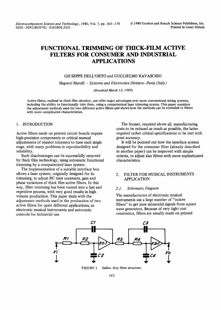
FIGURE Sallen-Key filter structure.
163

164 G. DELL’ORTO AND G. RAVASCHIO
where polynomial coefficients have been dimensionedto give a Chebysheff low-pass characteristic of fourthorder.
The frequency response is outlined in Figure 3,showing a ripple of 2 dB in the pass band and anattenuation of about 35,5 dB/octave in the stopband, considered quite satisfactory for musicalinstruments manufacturers.
FIGURE 2 Active element in Sallen-Key filter.
circuit boards but high-precision capacitors and amanual individual adjustment are not alwayssufficient to generate sounds of acceptable andconstant quality from assembled instruments.
Thick film active filters replace older versionswith advantages in cost and performance, thanksto a proper circuits structure, which includesgeneral-purpose transistors and large-tolerancecapacitors and is suitable for functional automatictrimming.
The filter circuit is based on the well-knownSallen-Key structure (Figure 1). The active elementin each stage is a unity-gain amplifier, implementedwith two transistors (Figure 2). The transferfunction is
Vo KRxRCxCp + [RxCz +RCz +RC(1-K)]p +
KR3R4CaCaP + [R3Ca +R4Ca +RC(1-K)]p + 1
(1)
2.2 Functional Trimming
The actual reproduction of the calculated filtercharacteristic requires the trimming of frequencyresponse in each stage, that is the polynomialcoefficients of Eq. 1 must reach their theoreticalvalues. With the first step, time constants R1C1,RC of the first stage and Ra Ca, RaCa of thesecond stage are functionally adjusted, to reach thenominal values of pz coefficients. In the secondstep, gains K1 andK must be adjusted also tocompensate for errors deriving from cross termsR C and Ra Ca and this is achieved by trimmingresistors r (Figure 2), affecting the stage gains. SinceRICI >>RC andRaCa >>RaC4, very smalldeviations ofK and K: close to the unity value aresufficient to obtain the desired adjustment.
The block diagrams of the interface device areshown in Figures 4 and 5.
In the first section, a voltage generator G suppliesa sinusoidal signal VG to the network RxCx undertrimming and to a reference network RR CR, withnominal value time constant.
Their outputs are connected, through twopeak-detectors, to the trimming system, whichcompares the two d.c. voltage levels and stopscutting resistor Rx when VAI VB I, that is
FIGURE 3 Frequency response of filter. FIGURE 4 Block diagram of interface to laser (No. 1).

THICK FILM ACTIVE FILTERS 165
laerecraj I_. ro ZAS.
FIGURE 5 Block diagram of interface to laser (No. 2).
" i’ :’ :’ ’’ I ,|
-’I ,I _I_’, l ,
FIGURE 6 Frequency responses of electronic organ fters.
RxCx RR CR. In the second section, a sinusoidalsignal at the stage tuning frequency, is sent topeak-detector directly and to peak-detector 2through a divider, with ratio equal to H and throughthe stage to be adjusted. The d.c. voltage levels fromthe peak detectors are supplied to the trimmingsystem which cuts resistor r until the stage gainreaches the nominal value H.
The most important advantage of this comparisonmethod lies in its precision and reproducibility, notaffected by precision and stability of the voltagegenerator G.
An electronic musical organ usually includesseven filters with seven different cut-off frequencies,ranging from 100 Hz to 8500 Hz.
The complete kit is obtained from two modules,using the same set of masks, with changes of softwareonly.
The basic thick-film module is screen-printed on a38.1 x 16.9 mtn. ceramic substrate. Add-oncomponents are four general purpose transistors inSOT23 case and four multi-layer ceramic chipcapacitors with a tolerance of +20%.
Figure 6 describes the frequency responses of
166 G. DELL’ORTO AND G. RAVASCHIO
C4
R6
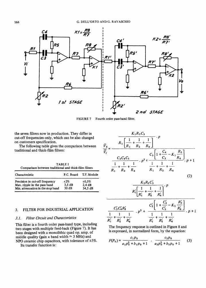
FIGURE 7 Fourth order pass-band filter.
the seven filters now in production. They differ incut-off frequencies only, which can be also changedon customers specification.
The following table gives the comparison betweentraditional and thick-film filters:
TABLEComparison between traditional and thick-film filters
Characteristic P.C. Board T.F. Module
Precision in cut-off frequency +/-2% +/-0,5%Max. ripple in the pass band 3,5 dB 2,4 dBMin. attenuation in the stop band 30 dB 34,5 dB
3. FILTER FOR INDUSTRIAL APPLICATION
3.1. Filter O’rcuit and Characteristics
This filter is a fourth order pass.band type, includingtwo stages with multiple feed-back (Figure 7). It hasbeen designed with a monolithic quad op. amp. ofmiddle quality (gain x band width - 3 MHz) andNPO ceramic chip capacitors, with tolerance of +5%.
Its transfer function is:
KaRsCa1
R1R1
.p
cccs1 1_---++Ra R2 R6
C3 1 +C4 -KC3
.p+l
-I- -I-R1 R2 R6
(2)
K2RsC’3
RI. ++.p
.p+l
The frequency response is outlined in Figure 8 andis expressed, in normalized form, by the equation:
F(eo)1P0 C2Po
a ip2o + b lPo + a2P2o + b2Po + 1(3)

THICK FILM ACTIVE FILTERS 167
i
FIGURE 8 Frequency response of pass-band filter.
where"
at 1,04296, bi 3.04874 10 -2,el 5,15806.10
a2 9,58811.10 -1 b2 2,92317.10 -2
e 5,15806.10 -’.The two filter stages are defined by their own
frequency responses, plotted in Figures 9 and 10.Tuning frequencies, practically coinciding with
maximum points, may be written as"
[o o/where
i=1,2
and then
Hi ci/bi Qi Xi/bi
,STAE ’AIN
" o2= 3242A/z
(4)
(s)
FIGURE 10 Frequency response of second filter stage.
JTAE ! GA/N
(///-a)d’a /
FIGURE 9
0I = 3/089Hz
= 3349
Frequency response of first filter stage.
3. 2 Functional Trimming: Principle ofOperationIn each stage, at its tuning frequency, there is nophase deviation between input and output signals.Eq. (2) and (4) show that frequencies and phase-deviations of the two stages depend on a and a2,p:-coefficients in the transfer function. Thus we cantune each stage at its own frequency, by trimmingresistors R2 and R, stopping the laser trimmer whenphase deviation becomes zero and p2.coefficientsreach the nominal values.We can then proceed to adjust gains Hi, according
to Eq. (5). Coefficients b l, c l, b: and c2 could notbe exactly equal to their respective theoretical valuesbut computer analysis shows that deviations arenegligible and cause a small vertical translation ofthe curve in Figure 8, without affecting filterselectivity.

168 G. DELL’ORTO AND G. RAVASCHIO
3.3 Functional Trimming: PracticalImplementation
The interface system is designed to use the standardd-c type computer controlled laser trimmer.
The block diagram of the phase-control section isshown in Figure 11, where Vi is a sinusoidal signal,supplied to this circuit and to the filter stage undertrimming at the same time. Figure 12a shows Viand Vo before trimming, which produce thewaveforms V1, V: and V3 of Figures 12b, c, d inthe interface network. When the phases of V0 andVi became equal, we have at the same instantV2 V3 "1" and V4 "0". At this moment, theoutput Vs from the memory unit goes up to "1"and stops the laser, trimming resistor R2 (or R).
Note that the one-shot no 2 is connected tosimilarly operate the AND-gate, to have the sametime-delay for signals in the two paths towards thelaser control input and, in this way, to improve thesystem precision.
This simple solution offers remarkable accuracyin operation, with response times in the order of afew nanoseconds. The interface section to controlgain adjustments is the same previously describedfor the consumer filter. The right values of gains are
ONE- ,,C/COT
F
,,EtUENTIAZ CIRCUITFIGURE 11 Block diagram of phase control section.
FIGURE 12control circuit.
(b)
I!
(c) i
l’(a) (d). Voltage waveforms the phase
reached by trimming resistors Ra and R (Figure 7),directly affecting K1 and K: parameters.
Actually, phase and gain adjustments are notindependent at all but affect each other in a smallamount, because of effective limitations in op. amp.characteristics, particularly gain bandwidth product.To compensate for the consequent error, theadjustment of each stage is achieved through foursteps, the first two of which are a coarse calibrationand the second two are a fine calibration. This isdescribed in Figure 13, concerning the first filterstage. First of all, the circuit is tuned at a frequency

THICK FILM ACTIVE FILTERS 169
FIGURE 13 Diagram showing stages of the first filter adjustment.
foi" < foi, then the gain is brought to a valueH1" < H1 and finally, by two other similar steps,final values fo and Ho are reached.
3.4 Hybrid Module Characteristics
The circuit is assembled on a ceramic substrate of22,4 x 38,1 mm., screen-printed on both sides.
Functional trimming resistors have rather largedimensions, to get final values with several cutswithout generating problems in noise and stability.
After functional trimming, modules are packagedinto a plastic case filled with epoxy resin and thentested with an automatic computerized process.
The following table gives main electricalcharacteristics with production tolerances:
fo 31,750kHz + 45 HzA o 0dB+0,3dBAf 1330Hz+80HzAf2 1923 Hz + 70 HzAmax Amax2 I< 0,3 dB
4. CONCLUSION
The thick film module of the pass-band filterdescribed in this paper is a good compromise in
performances, accuracy, dimensions and price.Other electrical circuits would be more suitablefor adjustment and accuracy but would require oneamplifier more in each stage.
The above-mentioned method of functionaltrimming combines a system of simple implemen-tation with very good operation in the productionprocess and, moreover, can be extended to otherkinds of filters.
The opportunity of performing functionaladjustment with several steps of increasing accuracyallows more critical circuits to be tuned.
REFERENCES
1. Dell’Otto, Ravaschio, "A low cost thick-film activefilter for consumer applications," E. C.C. Pr.oc. 1978,Anaheim (Ca-USA).
2. Sallen, Key, "A practical method of designing RCactive filters," 1RE Trans. CT 2 (1) 1955.
3. Bidstein, Filters actifs, Ed. Radio, Paris 1972.4. Temes, Mitra, Modern filter theory and design, J. Wiley
and Sons, New York 1973.5. Huelsman, Active RCfilters: Theory and application,
Dowden, Hutchinson and Ross, Stroutsburg (Pa-USA)1976.
6. Huelsman, Active filters, lumped, distributed, digitaland parametric, McGraw-Hill, New Yoxk 1970.
7. Tobey, Graeme, Huelsman, Operational amplifiers,McGraw-Hill, New York 1971.

170 G. DELL’ORTO AND G. RAVASCHIO
8. Active filters, AF 1 O0 universal active filters, NationalSemiconductor 1976.
9. Wang, Ott, Function circuits, McGraw-Hill, New York1976.
10. Graeme, Applications ofop. amplifiers, McGraw-Hill,New York 1973.
11. Graeme, Designing with op. amplifiers, McGraw-Hill,New York 1977.

International Journal of
AerospaceEngineeringHindawi Publishing Corporationhttp://www.hindawi.com Volume 2010
RoboticsJournal of
Hindawi Publishing Corporationhttp://www.hindawi.com Volume 2014
Hindawi Publishing Corporationhttp://www.hindawi.com Volume 2014
Active and Passive Electronic Components
Control Scienceand Engineering
Journal of
Hindawi Publishing Corporationhttp://www.hindawi.com Volume 2014
International Journal of
RotatingMachinery
Hindawi Publishing Corporationhttp://www.hindawi.com Volume 2014
Hindawi Publishing Corporation http://www.hindawi.com
Journal ofEngineeringVolume 2014
Submit your manuscripts athttp://www.hindawi.com
VLSI Design
Hindawi Publishing Corporationhttp://www.hindawi.com Volume 2014
Hindawi Publishing Corporationhttp://www.hindawi.com Volume 2014
Shock and Vibration
Hindawi Publishing Corporationhttp://www.hindawi.com Volume 2014
Civil EngineeringAdvances in
Acoustics and VibrationAdvances in
Hindawi Publishing Corporationhttp://www.hindawi.com Volume 2014
Hindawi Publishing Corporationhttp://www.hindawi.com Volume 2014
Electrical and Computer Engineering
Journal of
Advances inOptoElectronics
Hindawi Publishing Corporation http://www.hindawi.com
Volume 2014
The Scientific World JournalHindawi Publishing Corporation http://www.hindawi.com Volume 2014
SensorsJournal of
Hindawi Publishing Corporationhttp://www.hindawi.com Volume 2014
Modelling & Simulation in EngineeringHindawi Publishing Corporation http://www.hindawi.com Volume 2014
Hindawi Publishing Corporationhttp://www.hindawi.com Volume 2014
Chemical EngineeringInternational Journal of Antennas and
Propagation
International Journal of
Hindawi Publishing Corporationhttp://www.hindawi.com Volume 2014
Hindawi Publishing Corporationhttp://www.hindawi.com Volume 2014
Navigation and Observation
International Journal of
Hindawi Publishing Corporationhttp://www.hindawi.com Volume 2014
DistributedSensor Networks
International Journal of