functional servicing & preliminary stormwater … · preliminary stormwat management report...
TRANSCRIPT

FUNCTIONAL SERVICING &
PRELIMINARY STORMWATER
MANAGEMENT REPORT
133 & 137 MAIN STREET EAST
“BURGESS ESTATES”
TOWN OF GRIMSBY
NIAGARA REGION
PREPARED FOR:
BURGESS HERITAGE ESTATES INC.
PREPARED BY:
C.F. CROZIER & ASSOCIATES INC.
2800 HIGH POINT DRIVE, SUITE 100
MILTON, ON L9T 6P4
JUNE 2019
CFCA FILE NO. 863-5050
The material in this report reflects best judgment in light of the
information available at the time of preparation. Any use which
a third party makes of this report, or any reliance on or decisions
made based on it, are the responsibilities of such third parties.
C.F. Crozier & Associates Inc. accepts no responsibility for
damages, if any, suffered by any third party as a result of
decisions made or actions based on this report.
Burgess Heritage Estates Inc. Functional Servicing & Preliminary Stormwater Management Report
133 & 137 Main Street East, Town of Grimsby June 2019
C.F. Crozier & Associates Inc.
Project No. 863-5050
Revision Number Date Comments
Rev.0 June 2019 Issued for First Submission

Burgess Heritage Estates Inc. Functional Servicing & Preliminary Stormwater Management Report
133 & 137 Main Street East, Town of Grimsby June 2019
C.F. Crozier & Associates Inc.
Project No. 863-5050
TABLE OF CONTENTS
1.0 INTRODUCTION ................................................................................................................... 1
2.0 SITE DESCRIPTION ................................................................................................................ 1
3.0 WATER SERVICING .............................................................................................................. 2
3.1 Existing Water Servicing ............................................................................................... 2
3.2 Design Water Demand ................................................................................................. 2
3.3 Fire Flow Demand ......................................................................................................... 2
3.4 Proposed Water Servicing............................................................................................ 3
4.0 SANITARY SERVICING ......................................................................................................... 3
4.1 Existing Sanitary Servicing ........................................................................................... 3
4.2 Design Sanitary Flow .................................................................................................... 4
4.3 Proposed Sanitary Servicing ........................................................................................ 4
5.0 DRAINAGE CONDITIONS .................................................................................................... 4
5.1 Existing Storm Servicing ............................................................................................... 4
5.2 Existing Drainage .......................................................................................................... 5
5.3 Proposed Drainage ...................................................................................................... 5
6.0 STORMWATER MANAGEMENT ............................................................................................ 6
6.1 Stormwater Quantity Control ....................................................................................... 6
6.2 Stormwater Quality Control ......................................................................................... 7
7.0 RELOCATION OF STORM SEWER ......................................................................................... 7
8.0 EROSION AND SEDIMENT CONTROLS DURING CONSTRUCTION ....................................... 8
9.0 CONCLUSIONS AND RECOMMENDATIONS ....................................................................... 8
Burgess Heritage Estates Inc. Functional Servicing & Preliminary Stormwater Management Report
133 & 137 Main Street East, Town of Grimsby June 2019
C.F. Crozier & Associates Inc.
Project No. 863-5050
LIST OF TABLES
Table 1: Estimated Design Water Demand
Table 2: Estimated Fire Demand Flows
Table 3: Estimated Sanitary Design Flows
Table 4: Land Area Comparison
Table 5: Post-Development Drainage Catchment Parameters for the Subject Site
Table 6: Post-Development Flow Rates
LIST OF APPENDICES
Appendix A: Water Demand Calculations
Appendix B: Sanitary Flow Calculations
Appendix C: Stormwater Management Calculations
LIST OF FIGURES
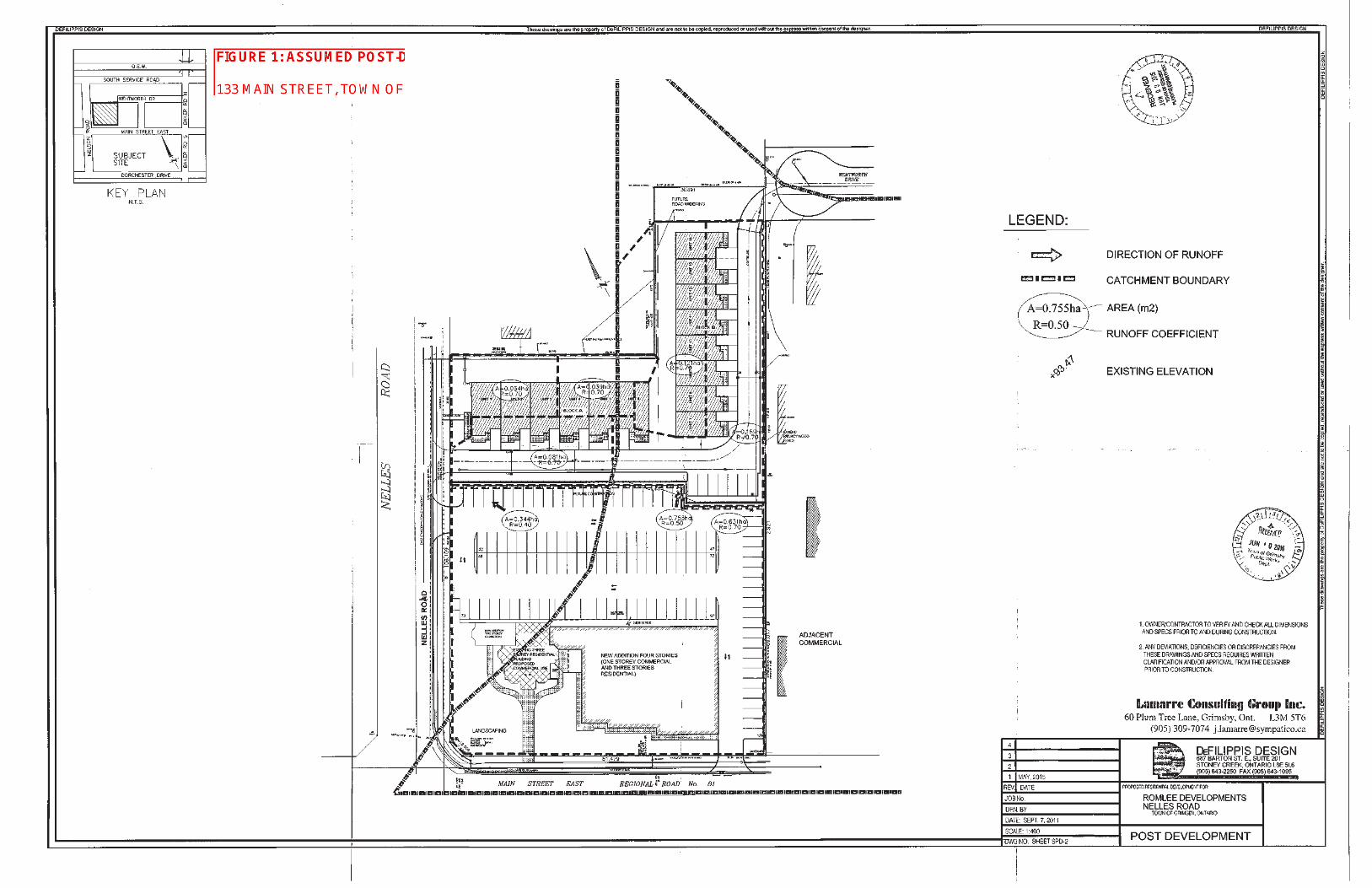
Figure 1: Assumed Post-Development Drainage
Figure 2: Post-Development Drainage

Burgess Heritage Estates Inc. Functional Servicing & Preliminary Stormwater Management Report
133 & 137 Main Street East, Town of Grimsby June 2019
C.F. Crozier & Associates Inc. Page 1 of 9
Project No. 863-5050
1.0 Introduction
Burgess Heritage Estates Inc. has retained C.F. Crozier & Associates Inc. (Crozier) to prepare a
Functional Servicing & Preliminary Stormwater Management Report. This report will support the
Zoning By-Law Amendment (ZBA) and Official Plan Amendment (OPA) to permit the
re-development at 133 &137 Main Street East (“Burgess Estates”) in the Town of Grimsby, Niagara
Region.
This report demonstrates that the proposed site can be re-developed in accordance with the Town
of Grimsby and Niagara Region guidelines from a functional servicing and preliminary stormwater
management perspective.
The proposed development is the second phase of a development for 133 & 137 Main Street East.
The first phase of the development, located north of the subject Site, has been completed and is
referred to as Josie’s Landing through this report.
The reports and design standards referenced during the preparation of this report include:
Region of Niagara Development Charge Background Study: Appendix A (Watson &
Associates Economists Ltd., April, 2017)
Niagara Region Water and Wastewater Master Servicing Plan: Volume III (2016)
Niagara Region Water and Wastewater Servicing Plan Volume IV (2016)
Ministry of Environment Design Guidelines for Sewage Works (2008)
Ministry of Environment Design Guidelines for Drinking Water Systems (2008)
Water Supply for Public Fire Protection (Fire Underwriters Survey, 1999)
Stormwater Management Feasibility Study: Proposed Residential Development 133 Main
Street East (Premier Engineering Solutions, February, 2014)
Stormwater Management Report, 133/137 Main Street East, (Lamarre Consulting Group Inc.,
April 2015)
2.0 Site Description
The subject property is approximately 0.66 ha and currently consists of one residential building and
accessory structure and a landscaped area. The residential building is classified as a heritage home.
The property, located in an area zoned as neighbourhood commercial, is bounded by residential
developments to the north (Josie’s Landing), Nelles Road North to the west, commercial units to the
east, and Main Street East to the south.
The elements envisioned for this development include:
A 148 unit – 5 storey residential building
Above ground parking with 39 spaces
Underground parking with 166 spaces
Site access to Nelles Road

Burgess Heritage Estates Inc. Functional Servicing & Preliminary Stormwater Management Report
133 & 137 Main Street East, Town of Grimsby June 2019
C.F. Crozier & Associates Inc. Page 2 of 9
Project No. 863-5050
As part of the re-development of the subject property the existing heritage home will be relocated
to the south west corner of the property and the accessory structure will be removed.
3.0 Water Servicing
3.1 Existing Water Servicing
The existing water servicing infrastructure close to the Site includes:
A 250 mm diameter watermain located along Nelles Road, adjacent to the site (Town of
Grimsby as-constructed drawing RD-84-53D, December 1984)
A 250 mm diameter watermain located along Main Street (TH-91-9C (Town of Grimsby as-
constructed drawing October 1989))
A fire hydrant located on Main Street, at the south east corner of the site (Town of Grimsby
as-constructed drawing TH-91-9C, October 1989)
A fire hydrant located along the west side of Nelles Road at the south west corner of the site
(Town of Grimsby as-constructed drawing RD-84-53D, December 1984)
3.2 Design Water Demand
The water demands for the proposed development were calculated with reference to the Niagara
Region Design Criteria. An average daily water demand of 300 L/capita/day was used in
conjunction with an occupancy density of 1.62 persons/unit for the 148 units in the proposed
development.
Table 1 summarizes the estimated water demands for the proposed re-development. Appendix A
contains detailed water demand calculations.
Table 1: Estimated Design Water Demand
Standard
Average Daily
Demand
(L/s)
Maximum Daily
Demand
(L/s)
Peak Hourly
Demand
(L/s)
Niagara Region Design Standards 0.83 1.67 3.33
Using the Niagara Region Design Criteria for domestic water demand, the estimated average daily
demand is 0.83 L/s and peak hourly water demand is 3.33 L/s.
3.3 Fire Flow Demand
The Fire Underwriters Survey method was used to estimate the fire flow requirements for the
proposed development. This calculation is based on basic building construction and gross floor area
of the development.
The proposed 5-storey residential building is assumed to have non-combustible construction,
therefore a construction coefficient of 0.8 was applied in the fire flow calculations (Water Supply for
Public Fire Protection by Fire Underwrites Survey, 1999). A gross floor area of 11,003 m2 is used as
outlined in the Site Plan (KNYMH Inc., May 29, 2019).

Burgess Heritage Estates Inc. Functional Servicing & Preliminary Stormwater Management Report
133 & 137 Main Street East, Town of Grimsby June 2019
C.F. Crozier & Associates Inc. Page 3 of 9
Project No. 863-5050
Table 2 summarizes the estimated fire flow and duration necessary to meet fire protection for the
proposed development.
Table 2: Estimated Fire Demand Flows
Method Demand Flow
(L/s)
Duration
(h)
Fire Underwriters Survey 183.3 2.25
The proposed fire service is required to accommodate a fire flow of 183.3 L/s (2,904 US GPM) for a
duration of 2.25 hours. Appendix A contains the Fire Underwriters Survey calculations. The building
Architect and the Mechanical Engineer will confirm the estimated fire flow demand.
Please note that the Fire Underwriters Survey value is a conservative estimate for comparison
purposes only. The Mechanical Engineer for this development will complete the required analyses
for fire protection and the Architect will design fire separation methods based on the required fire
flow rate, in order to meet municipally available flows and pressures.
A hydrant flow test will be conducted during the detailed design on this development.
3.4 Proposed Water Servicing
The development is proposed to be serviced by a 200 mm diameter PVC water service. The
proposed 200 mm diameter water service will connect to the existing 250 mm diameter watermain
along Nelles Road using a tapping sleeve and valve connection. A gate valve, as outlined in the
Town standards, is proposed at the property line, where the proposed 200 mm diameter water
service will split into a 200 mm fire line and 100 mm domestic service. The services will enter a water
meter/backflow preventor room before servicing each unit.
The Preliminary Site Servicing Plan (Drawing C103) illustrates the location and design of the proposed
water services.
4.0 Sanitary Servicing
4.1 Existing Sanitary Servicing
The existing sanitary sewage servicing close to the Site includes:
A 200 mm diameter sanitary sewer located along the south side of Main Street. At the
sanitary manhole located at the intersection of Main Street and Nelles Road, sanitary sewers
converge from the east, west and south; flowing north along Nelles Road (Town of Grimsby
as-constructed drawings SA-76-34P (January 1979) SA-76-34K (February 1979), and SA-76-34P
(January 1979))
A 250 mm diameter sanitary sewer is located along Nelles Road installed at a slope of 0.63%,
flowing north along Nelles Road (Town of Grimsby as-constructed drawings RD-84-53D
(December 1984) and TH-Y16-60B (June 2016))

Burgess Heritage Estates Inc. Functional Servicing & Preliminary Stormwater Management Report
133 & 137 Main Street East, Town of Grimsby June 2019
C.F. Crozier & Associates Inc. Page 4 of 9
Project No. 863-5050
4.2 Design Sanitary Flow
The Niagara Region Design Criteria was referenced to calculate the sanitary sewage design flows
for the proposed development. A unit sewage flow of 275 L/capita/day was used with an
occupancy density of 1.62 persons/unit for the 148 units in the proposed development. Infiltration
flow and a peaking factor were applied to the unit sewage flow to obtain the total estimated
design sewage flow.
Table 3 summarizes the estimated sanitary sewage design flows and Appendix B contains the
detailed calculations.
Table 3: Estimated Sanitary Sewage Design Flows
Standard
Average
Sewage Flow
(L/s)
Peaking
Factor
Peak Sewage
Flow (L/s)
Infiltration
Flow
(L/s)
Total Peak
Sewage Flow1
(L/s)
Niagara Region
Design Standards 0.76 4.00 3.05 0.19 3.24
Note: 1 Peak flow includes infiltration flow.
The proposed sanitary service was sized to convey a peak sanitary sewage flow of 3.24 L/s for the
development, as determined by the Niagara Region Design Criteria.
4.3 Proposed Sanitary Servicing
The development is proposed to be serviced by a 250 mm diameter sanitary sewer installed at a
slope of 2.0 %. This proposed 250 mm diameter sanitary sewer will connect to the sanitary manhole
(SAN MH 1) on Nelles Road. The proposed sanitary sewage service will be designed according to
the Niagara Region standards.
The Preliminary Site Servicing Plan (Drawing C103) illustrates the location of the sanitary sewer and all
connections. The buildings internal sanitary swage system will be designed according to the
Mechanical Engineer’s details and specifications.
Based on the design sanitary sewage demand calculations for the proposed development, we
conclude that the existing municipal infrastructure has sufficient capacity to support the proposed
development without any required external improvements.
5.0 Drainage Conditions
The drainage conditions for the site in both pre-development and post-development are outlined in
the following sections.
5.1 Existing Storm Servicing
The existing stormwater servicing infrastructure close to the Site includes:
A 300 mm diameter storm sewer running south to north along Nelles Road installed at a 1.5%
slope (Town of Grimsby as-built drawing RD-84-53D (December 1984))
A 300 mm diameter storm sewer becoming a 1200 mm diameter storm sewer running west to
east and then south to north along the private road (north of the Site) installed at a slope of
0.4% (Town of Grimsby as-built drawing TH-Y16-60B (June 2016))
Burgess Heritage Estates Inc. Functional Servicing & Preliminary Stormwater Management Report
133 & 137 Main Street East, Town of Grimsby June 2019
C.F. Crozier & Associates Inc. Page 5 of 9
Project No. 863-5050
A 600 mm diameter storm sewer running south to north through the easement at the eastern
side of the property (Instrument R084819 (Part 3, Plan 30R-14891) (Town of Grimsby as-built
drawing TH-Y01-16B (August 2001))
A 750 mm diameter storm sewer running west to east along Wentworth Drive (north of the
proposed Site), installed at a slope of 0.70% (Town of Grimsby as-built drawing TH-Y16-60B
(June 2016))
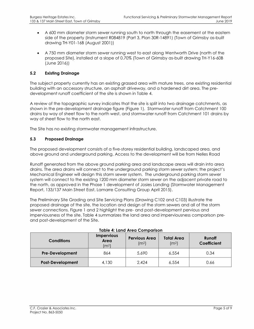
5.2 Existing Drainage
The subject property currently has an existing grassed area with mature trees, one existing residential
building with an accessory structure, an asphalt driveway, and a hardened dirt area. The pre-
development runoff coefficient of the site is shown in Table 4.
A review of the topographic survey indicates that the site is split into two drainage catchments, as
shown in the pre-development drainage figure (Figure 1). Stormwater runoff from Catchment 100
drains by way of sheet flow to the north west, and stormwater runoff from Catchment 101 drains by
way of sheet flow to the north east.
The Site has no existing stormwater management infrastructure.
5.3 Proposed Drainage
The proposed development consists of a five-storey residential building, landscaped area, and
above ground and underground parking. Access to the development will be from Nelles Road
Runoff generated from the above ground parking area and landscape areas will drain into area
drains. The area drains will connect to the underground parking storm sewer system; the project’s
Mechanical Engineer will design this storm sewer system. The underground parking storm sewer
system will connect to the existing 1200 mm diameter storm sewer on the adjacent private road to
the north, as approved in the Phase 1 development of Josies Landing (Stormwater Management
Report, 133/137 Main Street East, Lamarre Consulting Group April 2015).
The Preliminary Site Grading and Site Servicing Plans (Drawing C102 and C103) illustrate the
proposed drainage of the site, the location and design of the storm sewers and all of the storm
sewer connections. Figure 1 and 2 highlight the pre- and post-development pervious and
imperviousness of the site. Table 4 summarizes the land area and imperviousness comparison pre-
and post-development of the Site.
Table 4: Land Area Comparison
Conditions
Impervious
Area
(m2)
Pervious Area
(m2)
Total Area
(m2)
Runoff
Coefficient
Pre-Development 864 5,690 6,554 0.34
Post-Development 4,130 2,424 6,554 0.66
Burgess Heritage Estates Inc. Functional Servicing & Preliminary Stormwater Management Report
133 & 137 Main Street East, Town of Grimsby June 2019
C.F. Crozier & Associates Inc. Page 6 of 9
Project No. 863-5050
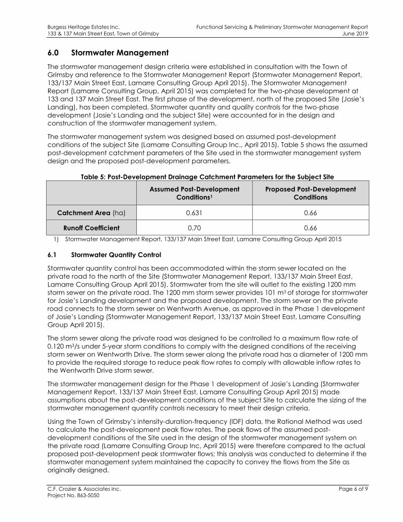
6.0 Stormwater Management
The stormwater management design criteria were established in consultation with the Town of
Grimsby and reference to the Stormwater Management Report (Stormwater Management Report,
133/137 Main Street East, Lamarre Consulting Group April 2015). The Stormwater Management
Report (Lamarre Consulting Group, April 2015) was completed for the two-phase development at
133 and 137 Main Street East. The first phase of the development, north of the proposed Site (Josie’s
Landing), has been completed. Stormwater quantity and quality controls for the two-phase
development (Josie’s Landing and the subject Site) were accounted for in the design and
construction of the stormwater management system.
The stormwater management system was designed based on assumed post-development
conditions of the subject Site (Lamarre Consulting Group Inc., April 2015). Table 5 shows the assumed
post-development catchment parameters of the Site used in the stormwater management system
design and the proposed post-development parameters.
Table 5: Post-Development Drainage Catchment Parameters for the Subject Site
Assumed Post-Development
Conditions1
Proposed Post-Development
Conditions
Catchment Area (ha) 0.631 0.66
Runoff Coefficient 0.70 0.66
1) Stormwater Management Report, 133/137 Main Street East, Lamarre Consulting Group April 2015
6.1 Stormwater Quantity Control
Stormwater quantity control has been accommodated within the storm sewer located on the
private road to the north of the Site (Stormwater Management Report, 133/137 Main Street East,
Lamarre Consulting Group April 2015). Stormwater from the site will outlet to the existing 1200 mm
storm sewer on the private road. The 1200 mm storm sewer provides 101 m3 of storage for stormwater
for Josie’s Landing development and the proposed development. The storm sewer on the private
road connects to the storm sewer on Wentworth Avenue, as approved in the Phase 1 development
of Josie’s Landing (Stormwater Management Report, 133/137 Main Street East, Lamarre Consulting
Group April 2015).
The storm sewer along the private road was designed to be controlled to a maximum flow rate of
0.120 m3/s under 5-year storm conditions to comply with the designed conditions of the receiving
storm sewer on Wentworth Drive. The storm sewer along the private road has a diameter of 1200 mm
to provide the required storage to reduce peak flow rates to comply with allowable inflow rates to
the Wentworth Drive storm sewer.
The stormwater management design for the Phase 1 development of Josie’s Landing (Stormwater
Management Report, 133/137 Main Street East, Lamarre Consulting Group April 2015) made
assumptions about the post-development conditions of the subject Site to calculate the sizing of the
stormwater management quantity controls necessary to meet their design criteria.
Using the Town of Grimsby’s intensity-duration-frequency (IDF) data, the Rational Method was used
to calculate the post-development peak flow rates. The peak flows of the assumed post-
development conditions of the Site used in the design of the stormwater management system on
the private road (Lamarre Consulting Group Inc, April 2015) were therefore compared to the actual
proposed post-development peak stormwater flows; this analysis was conducted to determine if the
stormwater management system maintained the capacity to convey the flows from the Site as
originally designed.

Burgess Heritage Estates Inc. Functional Servicing & Preliminary Stormwater Management Report
133 & 137 Main Street East, Town of Grimsby June 2019
C.F. Crozier & Associates Inc. Page 7 of 9
Project No. 863-5050
The stormwater management system was designed using the assumed drainage area of 0.631 ha
and runoff coefficient of 0.70 for the subject Site, as shown in Table 5 (Stormwater Management
Report, 133/137 Main Street East, Lamarre Consulting Group April 2015). The post-development
drainage boundaries used in the stormwater management system design is shown in Figure 3.
Proposed post-development conditions of the Site are a drainage area of 0.66 ha and runoff
coefficient of 0.66. Therefore, the proposed post-development conditions of the subject Site are
within the bounds of the assumed conditions used in Lamarre Consulting Groups stormwater
management system design.
Table 6 compares the peak stormwater flows from the assumed and proposed post-development
conditions of the subject Site. This analysis as shown in Table 6, demonstrates that the proposed
peak flows remain below the assumed peak stormwater flows used in Lamarre Consulting Groups;
design of the stormwater management system. Therefore, the stormwater storage system on the
private road has sufficient capacity to accept uncontrolled peak stormwater flows from the
proposed Site.
Appendix C contains complete stormwater management design calculations. The Preliminary
Servicing Plan (Drawing C103) illustrates the subject site’s storm sewer system.
Table 6: Post-Development Flow Rates
Storm
Post-Development Uncontrolled Flow Rate
(L/s)
Assumed Development1 Proposed Development2
2-year 0.083 0.082
5-year 0.109 0.106
10-year 0.126 0.123
25-year 0.148 0.144
50-year 0.159 0.156
100-year 0.175 0.171
1) Peak flows calculated using assumed post-development conditions of the Site (Stormwater
Management Report, 133/137 Main Street East, Lamarre Consulting Group April 2015)
2) Peak flow calculated for the proposed post-development conditions
6.2 Stormwater Quality Control
Stormwater quality control is accounted for in the design of the storm sewer for Phase 1 of the
development (Stormwater Management Report, 133/137 Main Street East, Lamarre Consulting
Group April 2015). The existing Josie’s Landing stormwater system has an in-line oil/grit separator.
7.0 Relocation of Storm Sewer
An existing storm sewer easement (R084819) is located along the eastern edge of the property. The
3.0 m easement contains a 600 mm diameter storm sewer conveying runoff from Main Street to the
750 mm storm sewer located on Wentworth Drive.

Burgess Heritage Estates Inc. Functional Servicing & Preliminary Stormwater Management Report
133 & 137 Main Street East, Town of Grimsby June 2019
C.F. Crozier & Associates Inc. Page 8 of 9
Project No. 863-5050
It is proposed that the storm sewer is to be removed and relocated to a location off Site, and for the
easement abandoned. Additional details regarding the relocation of the storm sewer easement will
be provided through the development application process, and more specifically through the site
plan process.
8.0 Erosion and Sediment Controls During Construction
Erosion and sediment controls will be installed prior to the beginning of any construction activities.
They will be maintained until the site is stabilized or as directed by the Site Engineer and/or the Town
of Grimsby. The Preliminary Erosion & Sediment Control Plan (Drawing C101) identifies the location of
the recommended controls. The erosion controls will be inspected after each significant rainfall
event and maintained in proper working condition.
The on-site erosion and sediment controls during construction include:
Heavy Duty Silt Fencing
Silt fencing will be installed on the perimeter of the site to intercept sheet flow. Additional silt fence
may be added based on field decisions by the Site Engineer and the Owner, prior to, during and
following construction
Rock Mud Mat
A rock mud mat will be installed at the entrance to the construction zone to prevent mud tracking
from the site onto surrounding lands and the perimeter roadway network. All construction traffic will
be restricted to this access only.
Sediment Control Devices
The existing catch basins on the private road north of the Site will be equipped with Terrafix
‘Siltsacks’.
9.0 Conclusions and Recommendations
Based on the information offered in this report, the proposed development of the Site, including a
148-unit 5-storey residential building, 39 above ground parking spaces, and 166 underground
parking spaces, can be serviced from a servicing and stormwater management perspective.
We offer the following conclusions:
Design peak water demand for the proposed development is 3.33 L/s and a fire flow of
183.3 L/s for 2.25 hours is required
Peak sanitary sewage flow for the proposed development is 3.24 L/s
Sanitary conveyance for the proposed development will be met using a 250 mm diameter
PVC sanitary sewer that connects to the sanitary sewer on Nelles Road
Stormwater quantity and quality control will be provided by the stormwater management
system, as approved in Phase 1 of the development (Josie’s Landing)
Existing 600 mm storm sewer in eastern easement is proposed to be removed and relocated,
and the easement abandoned
Erosion and Sediment Controls will be provided at all stages of construction

Burgess Heritage Estates Inc. Functional Servicing & Preliminary Stormwater Management Report
133 & 137 Main Street East, Town of Grimsby June 2019
C.F. Crozier & Associates Inc. Page 9 of 9
Project No. 863-5050
Based on the above conclusions, we recommend the approval of the Zoning By-Law Amendment
(ZBA) and Official Plan Amendment (OPA), from the perspective of functional servicing and
preliminary stormwater management.
Respectfully submitted,
C.F. CROZIER & ASSOCIATES INC. C.F. CROZIER & ASSOCIATES INC.
Jordan Atherton, M.Sc., E.I.T. Madeline Carter, P.Eng.
Water Resources Project Engineer
I:\800\863 - Movengo\5050-133 Main St\Reports\2019.06.03 FSRSWM.docx

Burgess Heritage Estates Inc. Functional Servicing & Preliminary Stormwater Management Report
133 & 137 Main Street East, Town of Grimsby June 2019
C.F. Crozier & Associates Inc.
Project No. 863-5050
APPENDIX A
Water Demand Calculations

Project: Created By: TT Date: 1/18/2019
Project No.: 863-5050 JA Updated: 5/21/2019
0.66 ha
Population Density: 1.62 persons/unit
148
Population: 240
Water Demand:
71,928 L/day
0.83 L/s
2.0
4.0
Average Day = 0.83 L/s
Max Day = 1.67 L/s Max Day = Average Day Demand * Max Day
Peak Hour = 3.33 L/s Peak Hour = Average Day Demand * Peak Hour
Average
Daily
Water
Demand
(L/s)
Max Day
Demand
(L/s)
Peak
Hourly
Demand
(L/s)
0.83 1.67 3.33
Municipality
Niagara Region
Niagara Region Water & Wastewater Master Servicing
Plan (2016) Volume 3
Design Parameters
Average Demand (L/capita/d)
300
Max Day =
Peak Hour =
Average Daily Demand =
Peaking Factors (Residential)
Niagara Region Water & Wastewater Master Servicing Plan (2016)
Volume 3
133 & 137 Main Street
Domestic Water Demand
Notes & References
Site Area:
Number of units:
Checked By:
Region of Niagara Development Charge Background
Study Appendix A
I:\800\863 - Movengo\5050-133 Main St\Design\Civil_Water\2019.01.18 WaterDemand
Project: Created By: JA Date: 5/25/2019
Project No.: 863-5050 Checked By: NAS Updated: 5/28/2019
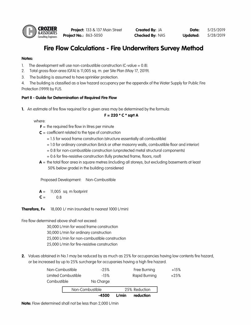
Notes:
where:
F =
C =
A =
A = 11,005
C = 0.8
Therefore, F= 18,000
Non-Combustible -25% Free Burning +15%
Limited Combustible -15% +25%
Combustible No Charge
25% Reduction
-4500 L/min reduction
Note: Flow determined shall not be less than 2,000 L/min
3. The building is assumed to have sprinkler protection.
4. The building is classified as a low hazard occupancy per the appendix of the Water Supply for Public Fire
Protection (1999) by FUS.
Non-Combustible
Proposed Development:
or be increased by up to 25% surcharge for occupanies having a high fire hazard.
Rapid Burning
30,000 L/min for wood frame construction
25,000 L/min for fire-resistive construction
25,000 L/min for non-combustible construction
30,000 L/min for ordinary construction
Non-Combustible
sq. m footprint
L/ min (rounded to nearest 1000 L/min)
Fire flow determined above shall not exceed:
133 & 137 Main Street
Fire Flow Calculations - Fire Underwriters Survey Method
Part II - Guide for Determination of Required Fire Flow
1. An estimate of fire flow required for a given area may be determined by the formula:
2. Values obtained in No.1 may be reduced by as much as 25% for occupancies having low contents fire hazard,
= 1.0 for ordinary construction (brick or other masonry walls, combustible floor and interior)
= 0.8 for non-combustible construction (unprotected metal structural components)
the total floor area in square metres (including all storeys, but excluding basements at least
F = 220 * C * sqrt A
50% below grade) in the building considered
= 0.6 for fire-resistive construction (fully protected frame, floors, roof)
= 1.5 for wood frame construction (structure essentially all combustible)
the required fire flow in litres per minute
coefficient related to the type of construction
1. The development will use non-conbustible construction (C-value = 0.8).
2. Total gross-floor-area (GFA) is 11,005 sq. m. per Site Plan (May 17, 2019).
Project: Created By: JA Date: 5/25/2019
Project No.: 863-5050 Checked By: NAS Updated: 5/28/2019
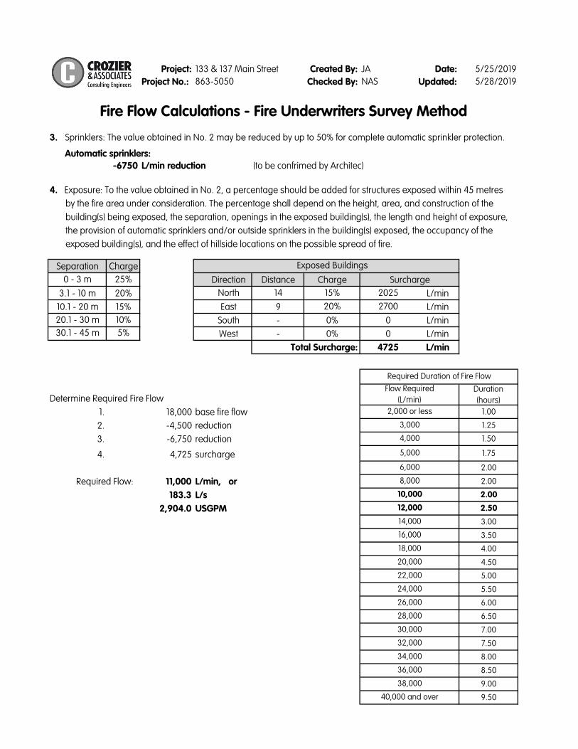
Automatic sprinklers:
-6750 L/min reduction (to be confrimed by Architec)
4. Exposure: To the value obtained in No. 2, a percentage should be added for structures exposed within 45 metres
by the fire area under consideration. The percentage shall depend on the height, area, and construction of the
building(s) being exposed, the separation, openings in the exposed building(s), the length and height of exposure,
the provision of automatic sprinklers and/or outside sprinklers in the building(s) exposed, the occupancy of the
exposed building(s), and the effect of hillside locations on the possible spread of fire.
Separation Charge
0 - 3 m 25% Direction Distance Charge
3.1 - 10 m 20% North 14 15% 2025 L/min
10.1 - 20 m 15% East 9 20% 2700 L/min
20.1 - 30 m 10% South - 0% 0 L/min
30.1 - 45 m 5% West - 0% 0 L/min
4725 L/min
Duration
(hours)
1. 18,000 base fire flow 1.00
2. -4,500 reduction 1.25
3. -6,750 reduction 1.50
4. 4,725 surcharge 1.75
2.00
11,000 L/min, or 2.00
183.3 L/s 2.00
2,904.0 USGPM 2.50
3.00
3.50
4.00
4.50
5.00
5.50
6.00
6.50
7.00
7.50
8.00
8.50
9.00
9.50
20,000
Required Duration of Fire Flow
2,000 or less
Flow Required
(L/min)Determine Required Fire Flow
12,000
6,000
4,000
3,000
14,000
10,000
8,000
5,000
18,000
16,000
40,000 and over
38,000
36,000
34,000
32,000
30,000
28,000
26,000
24,000
22,000
133 & 137 Main Street
Fire Flow Calculations - Fire Underwriters Survey Method
Required Flow:
Exposed Buildings
Surcharge
Total Surcharge:
3. Sprinklers: The value obtained in No. 2 may be reduced by up to 50% for complete automatic sprinkler protection.

Burgess Heritage Estates Inc. Functional Servicing & Preliminary Stormwater Management Report
133 & 137 Main Street East, Town of Grimsby June 2019
C.F. Crozier & Associates Inc.
Project No. 863-5050
APPENDIX B
Sanitary Flow Calculations

Project: Created By: JA Date: 4/25/2019
Project No.: 863-5050 NAS Updated: 5/21/2019
0.66 ha
Population Density: 1.62 persons/unit
148
Population: 240
Average Daily Flow = 275.0 L/capita/d
Average Daily Flow = 0.76 L/s
M = 4.00 M = 1 + 14 / (4 + (p/1000)^.5)
Peak Flow = 3.05 L/s Peak Flow = Average Daily Flow * M
Infiltration Flow: Infiltration = 0.29 L/s/ha
Total Infiltration = 0.19 L/s
Total Peak Flow = 3.24 L/s Total Peak Flow = Peak Flow + Total Infiltration
Summary Table
Average
Daily Flow
(L/s)
Peaking
Factor
Peak Flow
(L/s)
Infiltration
Flow
(L/s)
Total Peak
Flow
(L/s)
0.76 4.00 3.05 0.19 3.24
Niagara Region Water & Wastewater Master Servicing
Plan (2016) Volume 4
Harmon Peak Factor:
Sanitary Design Flow:
Average Daily Flow = Average Daily Flow (L/cap./day)
* population / 86400
Average Flow (L/capita/d)
Design Parameters
275
Region of Niagara Development Charge Background
Study Appendix A
Niagara Region Water & Wastewater Master Servicing
Plan (2016) Volume 4
133 & 137 Main Street
Domestic Sanitary Design Flow
Notes & References
Site Area:
Number of units:
Checked By:
I:\800\863 - Movengo\5050-133 Main St\Design\Civil_Water\2019.01.18 SanDemand

Burgess Heritage Estates Inc. Functional Servicing & Preliminary Stormwater Management Report
133 & 137 Main Street East, Town of Grimsby June 2019
C.F. Crozier & Associates Inc.
Project No. 863-5050
APPENDIX C
Stormwater Management Calculations

Project: 133 Main Street
Project No.: 863-5050Created By: JA
Checked By:Date: 4/25/2019
Updated: 4/25/2019
Storm Data:
Time of Concentration: Tc = 10 min
2 yr 603.3 6 0.79 67.49
5 yr 785.59 6 0.79 87.89
10 yr 953.64 7 0.79 101.70
25 yr 1119.02 7 0.79 119.34
50 yr 1301.8 8 0.8 128.92
100 yr 1426.13 8 0.8 141.23
Area
(ha)
Area
(m2)
C
0.63 6310 0.70
Area
(ha)
Area
(m2)
CWeighted
Average C
0.24 2423.78 0.25 0.09
0.41 4130.42 0.9 0.57
0.66 6554.2 - 0.66
Note:
Equations:
Actual Post - Development Conditions2
Land Use
Total Site
Assumed Post-Development Conditions1
Land Use
Pervious
Impervious
Total Site
1. Area and runoff coefficient based on assumed developmet in 133/137 Main Street East, Stormwater
Management Report (Lamarre Consulting Group Inc., April 2015)
2. Area and runoff coefficient based on Site Plan (KNYMH Inc. March 2019)
Per Niagara Peninsula
Conservation Authority:
Stormwater
Management
Guidelines: Appendix H
(March 2010)
Note:
Modified Rational Calculations - Input Parameters
Return Period A B CI
(mm/hr)
Grimsby
Peak Flow
Qpost = 0.0028 • Cpost • i(Td) • AIntensity
� � �
��� � �
I:\800\863 - Movengo\5050-133 Main St\Design\Civil_Water\2019.02.14 Modified Rational Method
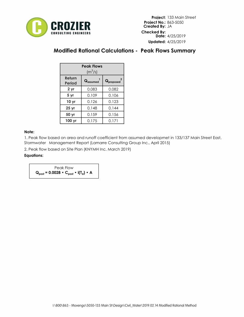
Project: 133 Main Street
Project No.: 863-5050Created By: JA
Checked By:Date: 4/25/2019
Updated: 4/25/2019
Return
PeriodQassumed
1Qproposed
2
2 yr 0.083 0.082
5 yr 0.109 0.106
10 yr 0.126 0.123
25 yr 0.148 0.144
50 yr 0.159 0.156
100 yr 0.175 0.171
Note:
Equations:
2. Peak flow based on Site Plan (KNYMH Inc. March 2019)
1. Peak flow based on area and runoff coefficient from assumed developmet in 133/137 Main Street East,
Stormwater Management Report (Lamarre Consulting Group Inc., April 2015)
Modified Rational Calculations - Peak Flows Summary
Peak Flows
(m3/s)
Peak Flow
Qpost = 0.0028 • Cpost • i(Td) • A
I:\800\863 - Movengo\5050-133 Main St\Design\Civil_Water\2019.02.14 Modified Rational Method

1
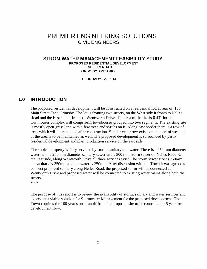
STORM WATER MANAGEMENT FEASIBILITY STUDY
PROPOSED RESIDENTIAL DEVELOPMENT 133 MAIN STREET EAST REAR TOWNHOUSE BLOCK GRIMSBY, ONTARIO
FEBRUARY 12, 2014
PREPARED BY
PREMIER ENGINEERING SOLUTIONS 3294 ALPACA AVENUE, MISSISSAUGA
ONTARIO, L5M 7V3
2
PREMIER ENGINEERING SOLUTIONS CIVIL ENGINEERS
STROM WATER MANAGEMENT FEASIBILITY STUDY PROPOSED RESIDENTIAL DEVELOPMENT
NELLES ROAD GRIMSBY, ONTARIO FEBRUARY 12, 2014
1.0 INTRODUCTION
The proposed residential development will be constructed on a residential lot, at rear of 133
Main Street East, Grimsby. The lot is fronting two streets, on the West side it fronts to Nelles
Road and the East side it fronts to Wentworth Drive. The area of the site is 0.431 ha. The
townhouses complex will comprise11 townhouses grouped into two segments. The existing site
is mostly open grass land with a few trees and shrubs on it. Along east border there is a row of
trees which will be remained after construction. Similar cedar row exists on the part of west side
of the area is to be maintained as well. The proposed development is surrounded by partly
residential development and plant production service on the east side.
The subject property is fully serviced by storm, sanitary and water. There is a 250 mm diameter
watermain, a 250 mm diameter sanitary sewer and a 300 mm storm sewer on Nelles Road. On
the East side, along Wentworth Drive all three services exist. The storm sewer size is 750mm,
the sanitary is 250mm and the water is 250mm. After discussion with the Town it was agreed to
connect proposed sanitary along Nelles Road, the proposed storm will be connected at
Wentworth Drive and proposed water will be connected to existing water mains along both the
streets. sewer.
The purpose of this report is to review the availability of storm, sanitary and water services and
to present a viable solution for Stormwater Management for the proposed development. The
Town requires the 100 year storm runoff from the proposed site to be controlled to 5 year pre-
development flow.

3
SATELLITE IMAGE OF THE SUBJECT SITE AND IT'S SERROUNDING AREA

4
2.0 EXISTING DRAINAGE
The runoff from the east part of the site flows in the east/north direction whereas on the west part
flows in the west direction. The water form east/north part discharges ultimately into Wentworth
Drive drainage system and from west part into Nelles Road drainage system.
3.0 STORM WATER MANAGEMENT CRITERIA AND METHODOLOGY
Following design criteria and methodology had been adopted.
Pre development runoff coefficient to be adopted for the allowable release rate
Return Period for allowable storm runoff rate from the site= 5 Year
Return Period for Overland flow from the site= 100 Year
Stormwater quantity issue to be addressed through the implementation of temporary runoff
detention on the site.
4.0 PROPOSED STORM DRAINAGE SCHEME
The proposed storm drainage scheme is summarized as follows:
Accomplishment of a minor/major drainage system consisting respectively of an on site storm
drainage system and overland flow route.
Limit runoff rate from the site to less than equal to the 5-Year release rate for all design storms
up to the 100-Year storm with the implementation of detention facilities.
Installation of storm water quality treatment unit.
4.1 PROPOSED MINOR STORM DRAINAGE SCHEME
The proposed storm sewer system within the site has been designed using formula for 5 year
return storm. The site will be serviced by serviced by a minor drainage system consisting of a
network of catchbasins connected to on-site storm sewers. The Storm Design Sheet is shown in
Appendix A1.

5
4.2 PROPOSED MAJOR STORM DRAINAGE SCHEME
The site will be graded such that runoff in excess of the allowable release rate will be
temporarily detained on the site in the super pipes and the detention pond. A major storm flow
in excess of the storage capacity will be directed towards Wentworth Drive and Nelles Road.
5.0 QUANTITY CONTROL
5.1 WEIGHTED RUNOFF COEFIFICIENT FOR THE PRE-DEVELOPMENT AREA
As discussed in section 2.0, the storm runoff from the site is discharging through sheet flow
towards Nelles Road and Wentworth. Therefore the site has been divided into two zones, namely
Area A1 and Area2. The drainage areas and their runoff coefficient have been depicted in the
schematic drawing(see Appendix A2)
In the table below have been shown existing land use and its areas and runoff coefficients for
Areas A1 and Area2.
5.1.1 Runoff Coefficient For Area 1 (Wentworth Drive)
Exist Land Use
Area (m2)
Runoff Coefficient
Area x Run off
Coefficient
Grass area
2530
0.25
632.5
Total Area 2530 632.5
Pre-Development Runoff Coefficient =632.5/2530 =0.25
5.1.2 Runoff Coefficient For Area 2 (Nelles Road)
Exist Land Use
Area (m2)
Runoff Coefficient
Area x Run off
Coefficient
Grass area
1715
0.25
428.75
Paved areas
65
0.90
58.5
Total site 1780 487.25

6
Pre - Development Composite Runoff Coefficient = 487.25/1780 =0.274
5.2 WEIGHTED RUNOFF COEFIFICIENT FOR THE POST-DEVELOPMENT AREA In the table below have been shown proposed land use and its areas and runoff coefficients. For Post Development Drainage plan refer to Appendix A3.
Exist Land Use
Area (m2)
Runoff Coefficient
Area x Run off
Coefficient
West units
676
0.90
608
North units 676 0.90 608
Paved areas
1468
0.90
1321
Landscale
1490
0.25
373
Total site 4310 2910
Post Development Composite Runoff Coefficient = 2910/4310 =0.68
5.3 ALLOWABLE STORM RUNOFF RELEASE RATE
As mentioned in section 1.0, the on-site drainage system will be connected to the existing
storm sewer on Wentworth. The allowable release rate will be such that it will not increase
more than the 5 year pre-development runoff from Area A1.
Area of the site = 0.253 hectares
Runoff coefficient = 0.25
From the area and runoff coefficient, estimated allowable release rate form the site will be
calculated as follows:

7
Allowable runoff rate = 2.78CIA
Estimated time of concentration = 10 min.
Runoff coefficient = 0.25
Rainfall intensity (5 year storm) = 785.59/(t+6)0.79
= 785.59/(10+6)0.79
= 87.89 mm/hr
Allowable estimated release rate = 2.78x0.25x87.89x0.253 = 15.45 L/sec
5.3 STORAGE VOLUME
Spreadsheet calculations have been used to determine the detention volume requirements when
the post development flow from the area is controlled to get the overall discharges from the
site to allowable release rate.
The release rate from the parking area will be difference of the controlled release rate from the
site and the roof discharges.
Release rate from the site =15.45 L/sec
The storage volume calculations have been shown in Appendix B1. The volume required for
storage is 88.93 m3. This volume will be detained in a super pipe of 750 diameter size and
other smaller size storm sewers along with a detention pond at the rear of Block A ( See Dwg
NELLES-GSP-001).
5.3.1 SUPER PIPE STORAGE
Detention Volume = [Length of 750mm super-pipe x cross sectional area of the pipe]
Length of 750 pipe = [55 + 27 + 65.6]
= 147.6m
Cross sectional Area = 0.7854x0.752
=0.4417m2
Volume of Detained Water = 147.6 x 0.4417
= 65.19m3
Detention Volume in 450mm pipe
=[Length of 450mm pipe x cross sectional area of the pipe]
Length of the 450mm pipe =[28 + 30.5]
=58.5m

8
Cross sectional Area of the Pipe= 0.7854x0.452
=0.159m
2
Volume of Detained Water = 58.5 x 0.159
= 9.3m3
Total Volume Stored in the Pipes= 65.19 + 9.3
=74.49m3
5.3.2 DETENTION POND STORAGE
As the total storage required is 88.93m3, the remaining volume (88.93-74.49 = 14.03) will be detained in
the proposed pond at the rear of Block ‘A’ (see the Site Servicing Drawing)
Detention Volume in the pond:
Length of the pond = 57.8m
Max depth = 0.3m
Minimum depth =0.15
Flat width =0.5m
Slope width =0.9m
Volume of the pond =[(0.3+0.15)/2x0.75 + (0.3+0.15)/4x0.9]x57.8
=[0.165 + 0.10] x 57.8
=0.265 x 57.8
=15.3m3
5.3.3 TOTAL STORAGE VOLUME
The total storage volume will be sum of storage volume in pipes and the detention pond.
Total Storage volume = 74.49 + 15.3
=89.79m3 > 88.93 O.K.
5.4 QUANTITY CONTROL UNIT
After going through a several trials for a suitable orifice pipe for the required discaharge and head available, we found that the standard sizes of PVC pipes cannot be proposed for the required conditions. Therefore, alternatively we are proposing Vortex valve of Model for the required control flow. Design details will be submitted with the detailed design submission
6.0 QUALITY CONTROL

9
To provide storm water quality control as required by the Town, the Model STC750 (or approved equal) is recommended for the proposed development. This Model is expected to treat 98% runoff annually and facilitate 84% annual TSS removal. The proposed storm water treatment facility will be maintained by the owner as per manufacturer recommendations. Removal efficiency sheet is attached in Appendix C.
7.0 GRADING AND OVERLAND FLOW
Grading will be designed in such a way that the runoff will be contained within the site. Overland 100 year storm flow will be directed towards Wentworth Drive site on the north and Nelles Road on the west.
8.0 CONCLUSION
The study shows that Stormwater Management scheme for 100 year storm can be implemented for the site without surcharging existing drainage system by construction of underground infiltration trench, installing super pipes and orifice to control flow from super pipe to existing drainage system in Wentworth Drive. The lot grading will be designed in such a way that storm water will not flow to adjacent properties. Overland flow will be directed to the site access in the north/east and west side of subject land. The proposed storm water management and drainage scheme will prevent erosion and flooding and will provide necessary control and adequate storm water detention facility. The proposed quality control system will provide required TSS removal from the flow and prevent any adverse influence to the existing drainage system. Prepared By: Muhammad Ismail P.Eng.

Burgess Heritage Estates Inc. Functional Servicing & Preliminary Stormwater Management Report
133 & 137 Main Street East, Town of Grimsby June 2019
C.F. Crozier & Associates Inc.
Project No. 863-5050
FIGURES

T
KEY PLANSCALE: N.T.S.
LEGEND
I:\800\863 - M
oven
go
\5050-133 M
ain
St\C
AD
\C
ivil\_Sh
eets\5050_FIG
01.d
wg
, 2019-06-03 2:29:55 P
M, A
uto
CA
D P
DF (H
ig
h Q
uality P
rin
t).p
c3

Burgess Heritage Estates Inc. Functional Servicing & Preliminary Stormwater Management Report
133 & 137 Main Street East, Town of Grimsby June 2019
C.F. Crozier & Associates Inc.
Project No. 863-5050
DRAWINGS

LEGEND
NN
KEY PLANSCALE: N.T.S.
FOR REVIEW
NOT FOR CONSTRUCTION
I:\800\863 - M
oven
go
\5050-133 M
ain
St\C
AD
\C
ivil\_Sh
eets\5050_101.d
wg
, ESC
, 2019-06-04 11:06:49 A
M,
sch
ristie, D
WG
To
P
DF.p
c3, P
revio
us p
ap
er size (863.60 x 558.80 m
m), 1:1

T
KEY PLANSCALE: N.T.S.
LEGEND
I:\800\863 - M
oven
go
\5050-133 M
ain
St\C
AD
\C
ivil\_Sh
eets\5050_102.d
wg
, 2019-06-03 2:26:46 P
M, A
uto
CA
D P
DF (H
ig
h Q
uality P
rin
t).p
c3

T
KEY PLANSCALE: N.T.S.
LEGEND
I:\800\863 - M
oven
go
\5050-133 M
ain
St\C
AD
\C
ivil\_Sh
eets\5050_103.d
wg
, 2019-06-03 2:20:11 P
M, A
uto
CA
D P
DF (H
ig
h Q
uality P
rin
t).p
c3