functional api model and usage guidelines implementation ... · pdf...
TRANSCRIPT

Network Processing Forum Software Working Group
Functional API Model and Usage Guidelines Implementation Agreement
22nd December 2004 Revision 1.0
Editor(s): Alistair Munro, U4EA Technologies Ltd., [email protected] Copyright © 2004 The Network Processing Forum (NPF). All Rights Reserved. This document and translations of it may be copied and furnished to others, and derivative works that comment on or otherwise explain it or assist in its implementation may be prepared, copied, published and distributed, in whole or in part, without restriction other than the following, (1) the above copyright notice and this paragraph must be included on all such copies and derivative works, and (2) this document itself may not be modified in any way, such as by removing the copyright notice or references to the NPF, except as needed for the purpose of developing NPF Implementation Agreements. By downloading, copying, or using this document in any manner, the user consents to the terms and conditions of this notice. Unless the terms and conditions of this notice are breached by the user, the limited permissions granted above are perpetual and will not be revoked by the NPF or its successors or assigns. THIS DOCUMENT AND THE INFORMATION CONTAINED HEREIN IS PROVIDED ON AN "AS IS" BASIS WITHOUT ANY WARRANTY OF ANY KIND. THE INFORMATION, CONCLUSIONS AND OPINIONS CONTAINED IN THE DOCUMENT ARE THOSE OF THE AUTHORS, AND NOT THOSE OF NPF. THE NPF DOES NOT WARRANT THE INFORMATION IN THIS DOCUMENT IS ACCURATE OR CORRECT. THE NPF DISCLAIMS ALL WARRANTIES, WHETHER EXPRESS, IMPLIED OR STATUTORY, INCLUDING BUT NOT LIMITED THE IMPLIED LIMITED WARRANTIES OF MERCHANTABILITY, TITLE OR FITNESS FOR A PARTICULAR PURPOSE AND NON-INFRINGEMENT OF THIRD PARTY RIGHTS.
The words "MUST", "MUST NOT", "REQUIRED", "SHALL", "SHALL NOT", "SHOULD", "SHOULD NOT", "RECOMMENDED", “MAY", and "OPTIONAL" in the remainder of this document are to be interpreted as described in the NPF Software API Conventions Implementation Agreement revision 1.0.
For additional information contact: The Network Processing Forum, 39355 California Street,
Suite 307, Fremont, CA 94538 +1 510 608-5990 phone [email protected]
Functional API Task Group 1

Network Processing Forum Software Working Group
Table of Contents 1 Revision History....................................................................................................................... 4 2 Scope and Purpose ................................................................................................................... 5 3 Normative References .............................................................................................................. 6 4 Terms, Acronyms and Abbreviations....................................................................................... 7 5 FAPI Project Overview ............................................................................................................ 9 6 Introduction ............................................................................................................................ 10 7 Architecture – Requirements, Principles and Structure ......................................................... 12 8 Composition of a FAPI Capable FE....................................................................................... 13 9 Interoperability of LFBs......................................................................................................... 16 10 The FE Model......................................................................................................................... 17 10.1 Naming of FEs ............................................................................................................ 17 10.2 State Model and Capability Model for the FE............................................................ 17 10.3 LFB Modeling within the FE...................................................................................... 17 10.4 FE Datapath Modeling – LFB Topology and Usage Guidelines................................ 27 11 The LFB Data Model ............................................................................................................. 34 11.1 LFB Capabilities ......................................................................................................... 34 11.2 Naming of LFBs ......................................................................................................... 34 11.3 General Data Type Definitions ................................................................................... 35 11.4 Metadata Definitions................................................................................................... 36 11.5 Frame Type Definitions .............................................................................................. 36 11.6 LFB Class Definitions................................................................................................. 36 12 Functional APIs...................................................................................................................... 40 13 Guidelines for LFB Selection and API Design ...................................................................... 41 13.1 Principles and Heuristics............................................................................................. 41 13.2 Inter-LFB State ........................................................................................................... 42 13.3 Expected Content of LFB Specifications.................................................................... 42 14 FAPI Relationship to Service APIs and Vendor APIs ........................................................... 43 14.1 Domain Specific APIs Top-to-Bottom, Single NPE................................................... 44 14.2 Specific and Generic APIs with Translation, Single NPE.......................................... 45 14.3 Multiple NPEs, 1 Service level:Many FAPI Calls...................................................... 45 14.4 Single NPE, Many Service Level:1 FAPI Call........................................................... 46
Functional API Task Group 2

Network Processing Forum Software Working Group
Table of Figures Figure 1. Generic Switch Architecture ......................................................................................... 13 Figure 2 Various mappings of LFB functionality to NPEs........................................................... 14 Figure 3 Examples of LFBs with various output combinations. .................................................. 18 Figure 4 Input modeling concepts (examples).............................................................................. 20 Figure 5 Representation of paired blocks ..................................................................................... 21 Figure 6 Illustrations of the use of the Topology and Encoded State Models............................. 29 Figure 7 An LFB topology example. ............................................................................................ 30 Figure 8 An example of configuring LFB topology. .................................................................... 33 Figure 9 Components of a Generic LFB Class Definition an Example for IPv4 ......................... 37 Figure 10 NPF API Layering........................................................................................................ 43 Figure 11 Options for calling FAPI functions via strongly-typed and generic LFB APIs ........... 44 Figure 12 Specific APIs at All Layers .......................................................................................... 44 Figure 13 Domain specific services API above generic functional API ...................................... 45 Figure 14 Multiple FAPI Invocations, Multiple NPEs ................................................................. 46 Figure 15 Multiple NPF Function calls resulting in a single NPE configuration entry................ 46 Figure 16 Generic Architecture Example ..................................................................................... 47 Figure 17 Basic ForCES CE separation from FE ......................................................................... 47 Figure 18 NPF and ForCES Interactions ...................................................................................... 48
Functional API Task Group 3

Network Processing Forum Software Working Group
1 Revision History Revision Date Reason for Changes 1.0 10/7/2004 Created Rev 1.0 of the implementation agreement by taking
the FAPI Model and Usage Guidelines draft (npf2002.340.35) and making minor editorial corrections.
Functional API Task Group 4

Network Processing Forum Software Working Group
2 Scope and Purpose An objective of the NPF is to encourage innovation and reuse of components by implementers and system integrators when building products that perform network processing functions. The role of the Software WG in achieving this objective is to specify a suitable set of application programming interface (API) implementation agreements that define a common boundary that lies between the controlling functions and the network processing silicon. These APIs require a framework in which interactions across this interface take place and the model described in this document provides this framework.
Functional API Task Group 5

Network Processing Forum Software Working Group
3 Normative References The following documents contain provisions, which through reference in this text constitute provisions of this specification. At the time of publication, the editions indicated were valid. All referenced documents are subject to revision, and parties to agreements based on this specification are encouraged to investigate the possibility of applying the most recent editions of the standards indicated below. 1. [SWAPILEX] “Software API Framework Lexicon”,
http://www.npforum.org/techinfo/LexiconIAv1.pdf, Network Processing Forum, ,2002
2. [SWFRAMEWORK] “API Software Framework”, http://www.npforum.org/techinfo/NPF-SwAPI-Software_FrameworkIAv1.pdf, Network Processing Forum, 2002
3. [RFC2475] “An Architecture for Differentiated Services”, S.Blake, et al, Dec. 1998. (www.ietf.org/rfc/rfc2475.txt)
4. [RFC3031] “Multiprotocol Label Switching Architecture”, E. Rosen, Jan. 2001, (www.ietf.org/rfc/rfc3031.txt)
5. [RFC3270] “Multi-Protocol Label Switching (MPLS) – Support of Differentiated Services”, F Le Faucheur, May 2002 (www.ietf.org/rfc/rfc3270.txt)
6. [FORCESREQ, RFC3654] ”Requirements for Separation of IP Control and Forwarding”, H. Khosravi, T. Anderson et al, July 2002. (http://www.ietf.org/rfc/rfc3654.txt)
7. [FORCESCH] Charter of the IETF ForCES Working Group, http://www.ietf.org/html.charters/forces-charter.html
8. [MESSLFB] ”Messaging LFB IA”, http://www.npforum.org/techinfo/messaging_lfb_npf2003.504.10.pdf, Network Processing Forum, April 2004
9. [FAPITOPO] ”FAPI Topology Discovery API”, work in progress, Network Processing Forum, 2002.
10. [MSGTGIA] “NPF Message Layer Implementation Agreement”, http://www.npforum.org/techinfo/Messaging_IA.pdf, Network Processing Forum, 2002
11. [LFBTEMPLATE] “NPF LFB Template: <LFB Name> LFB and Functional API Implementation Agreement”, Network Processing Forum, 2003. Note: this is an internal document for NPF use in drafting FAPI IAs.
Functional API Task Group 6

Network Processing Forum Software Working Group
4 Terms, Acronyms and Abbreviations The following terms, acronyms and abbreviations, cross-referenced to those defined in the lexicon,, [SWAPILEX], (indicated in italics), are used in this document:
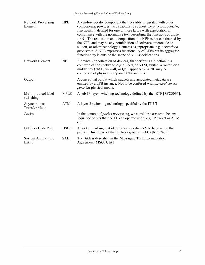
Control Element CE The CE is a control process in the control plane.
Blade - A realization constructed using NPEs, comprising one or more FEs, in a physical format that can be installed in a packet-processing system such as a router or switch.
Forwarding Element FE A FE is modelled as a collection of logical functions (LFBs) whose relationship is expressed using a directed graph.
Input - A conceptual port at which packets and associated metadata are received by a LFB instance. Not to be confused with physical ingress ports for physical media.
Logical Function Block
LFB A functionality of a scope defined by a manufacturer, by an organisation promoting common interfaces and mechanisms (such as the IETF), or by a standard of stated scope, e.g. published by the NPF. The functionality may include but is not limited to the processing of packets and/or metadata flowing through an NPE. A NPF Functional API provides an LFB-instance aware means of accessing (configuring, monitoring) the attributes and resources associated with the LFB instance. Note that we often use the term LFB without distinguishing between LFB class, the object that implements the class in the FE datapath, or LFB instance when we believe the implied reference is obvious for the given context.
LFB Class The template comprising datatype and associated operations upon the packets, metadata or other information, representing a fine-grained, logically separable and well-defined processing operation in the datapath. LFB classes are the basic building blocks of the FE model.
LFB Type Identifier An identifier that is used in APIs and protocols to distinguish the LFB class associated with an LFB instance.
LFB instance As a packet flows through an FE along a datapath, it flows through one or more LFB instances, each implementing a certain LFB class. There may be multiple instances of the same LFB in an FE's datapath.
LFB Attribute The functional and non-functional properties of an LFB. In programming terms these are the Operational parameters of the LFBs that must be visible to the CEs
LFB Resource The realization in an LFB implementation of the attributes of that LFB type.
Functional API Task Group 7
Network Processing Forum Software Working Group
Network Processing Element
NPE A vendor-specific component that, possibly integrated with other components, provides the capability to support the packet-processing functionality defined for one or more LFBs with expectation of compliance with the normative text describing the functions of those LFBs. The realisation and composition of a NPE is not constrained by the NPF, and may be any combination of software, microcode or silicon, or other technology elements as appropriate, e.g. network co-processors. A NPE expresses functionality of LFBs but its aggregate functionality is outside the scope of NPF specifications.
Network Element NE A device, (or collection of devices) that performs a function in a communications network, e.g. a LAN, or ATM, switch, a router, or a middlebox (NAT, firewall, or QoS appliance). A NE may be composed of physically separate CEs and FEs.
Output A conceptual port at which packets and associated metadata are emitted by a LFB instance. Not to be confused with physical egress ports for physical media.
Multi-protocol label switching
MPLS A sub-IP layer switching technology defined by the IETF [RFC3031].
Asynchronous Transfer Mode
ATM A layer 2 switching technology specifed by the ITU-T
Packet In the context of packet processing, we consider a packet to be any sequence of bits that the FE can operate upon, e.g. IP packet or ATM cell.
DiffServ Code Point DSCP A packet marking that identifies a specific QoS to be given to that packet. This is part of the Diffserv group of RFCs [RFC2475]
System Architecture Entity
SAE The SAE is described in the Messaging TG Implementation Agreement [MSGTGIA]
Functional API Task Group 8

Network Processing Forum Software Working Group
5 FAPI Project Overview The Functional API project is chartered to deliver the following: • An analysis of the prior art upon which the architecture, functions and mechanisms of the Functional
APIs are based; • Requirements for Functional APIs; • Specification of the framework for defining Functional APIs; and • Functional API Implementation Agreements. The IA describes the framework in which the functions of the forwarding path of a network element operate and interoperate and give guidelines on their definition and usage.
Functional API Task Group 9

Network Processing Forum Software Working Group
6 Introduction Service APIs (SAPIs) provide an interface that hides the detail of the network element. By contrast, Functional APIs (FAPIs) are aware of the composition of the network element and require the ability to address individual functions in its forwarding path(s). Thus a FAPI is used by vendors to expose the resources that underly network element-level functionality. It is expected that the set of functions exposed in any particular device will vary just as the network processing elements (NPEs) on different boards vary. While variance in the set of exposed functions is expected, for each type of function the methods used and the semantics of the function is expected to be vendor agnostic and consistent. Thus, while one board, i.e. a physical realization of a forwarding element (FE) might expose functionality for IPv4 forwarding and NAT, perhaps based on a programmable network processor, and another board might expose functionality for IPv4 forwarding and MPLS using a generic classification chip and QoS chip, the IPv4 functionality exposed would be the same, at least insofar as to the syntax used. Differences might exist in resource capabilities (supported numbers of forwarding entries, maximum rate of forwarding, etc.) but not in syntax. The same method would be used to add a forwarding entry, using the same data structures. To capture the diversity of function offered by network elements (NEs), we break down the functionality of an FE into smaller functional elements, known as Logical Functional Blocks, (LFBs). An LFB has a specific function in the FE and receives well-defined inputs and outputs. It can be composed together with other LFBs to build a complete packet processing chain. The concept of the LFB has also been adopted by the ForCES WG of the IETF [FORCESCH, FORCESREQ] and many of the modeling principles used by ForCES have been adopted in the NPF FAPI model. There are thus significant similarities between the ForCES model and the NPF FAPI model but it must not be forgotten that ForCES is essentially a distributed processing abstraction whereas the FAPI model deals with tangible resources such as processors, registers and memory. In order to expose the variation in functions provided by different realizations the FE is accessed using two sets of APIs. These are the FAPI Topology Discovery APIs, [FAPITOPO], which allow the structure of a FE to be obtained, in particular the identities of the function blocks and thence resources in it, and the FAPI Logical Function Block (LFB) APIs, which allow access to functions’ resources. The FAPI Topology Discovery APIs are used to learn the presence of types of functions on a device and acquire handles used to configure instances of those functions. The learning aspects of the FAPI Topology Discovery APIs are expected to be used in scenarios where, for example, a blade is “hot plugged” into a system and the control plane must learn the type of blade it is. The handle retrieval methods of the FAPI Topology Discovery APIs are used both in “hot plug” scenarios and in static configuration scenarios, and allow a client program to programmatically acquire handles for use in configuring the tables which control forwarding device behavior. The FAPI LFB APIs are domain specific APIs that manage the behavior of forwarding plane functions, and the tables used to configure them. FAPI LFB APIs will be defined for many domains including IP, MPLS, DiffServ, ATM, and interfaces of various types. It is expected that reuse of APIs between different domains will be important, thus function signatures for common operations such as retrieving counters or deleting table entries should be reused between different LFB APIs as appropriate. This document is organized as follows: • Section 4 introduces definitions of terms used in the model with associated abbreviations where
appropriate; • Section 7 describes the working assumptions about FEs, their functionality and configurations in
order to establish the requirements for the FAPI Model; • Section 8 describes how a FE is composed from basic building blocks, or FE components; • Section 9 states the mechanisms for achieving interoperability between these components; • Section 10 introduces the first part of the FAPI model, which is for the FE; • Section 11 introduces the LFB data model part of the model;
Functional API Task Group 10

Network Processing Forum Software Working Group
• Section 12 relates the functional API to the LFBs; and • Section 13 gives guidelines and examples.
Functional API Task Group 11

Network Processing Forum Software Working Group
7 Architecture – Requirements, Principles and Structure Devices implemented using network processors are highly diverse in performance, physical format and internal structure, being optimized for specific functions and market sectors. The FAPI model must allow any, and all, variations to be expressed without constraining form and function, and provide an element-aware programming framework in which LFB instances and their resources can be identified uniquely, their relationships with one another be expressed, e.g. in the information they share. The model must be consistent with the following assumptions: • The FAPI FE architecture, its elements and modeling approach to LFBs, FEs and the transfer of data
between CE and FE SHOULD be consistent with the ForCES model being specified by the IETF. Due to the objectives of the NPF in terms of physical realization of FEs and the constraints of hardware it is expected that some details will be different;
• A product constructed of network processors will contain one or more FEs. An FE is a hardware/software subsystem, typically a replaceable board or blade, designed for processing of network packets. Processing could include forwarding or termination of flows, according to the rules of one or more network protocols. In physical terms, a FE will be realized as a blade in a chassis, interconnected with other blades via a backplane or switching fabric;
• Manufacturers and system integrators will use components appropriate to the specification that a product must fulfill and will use NPF APIs to document and manage the exposed resources and interfaces in the FE. Evolution of the market may encourage the emergence of several frequently used configurations and, possibly, standard LFBs. The model MUST be able to express such configurations and functionality;
• The relationship between FAPIs and LFBs will normally be 1-1. However this model does not constrain alternatives, possibly vendor specific, where one FAPI is valid for more than one LFB or an LFB can be configured using multiple FAPIs;
• Functions in a FAPI specification operate across boundaries defined by the control interfaces of the NPEs that compose the FE. Termed the “vertical” direction. In general they will set and get the values in registers in the NPEs or memory tables (termed “resources”) shared in an implementation-specific way between the FAPI function implementation and the NPE;
• The processes in the FEs that implement the functions of an LFB may operate on packets passing through the FE, applying them in a way (e.g. in a certain sequence, or possibly in parallel) that may be vendor-specific, implicit in the standards that the product implements, or itself defines. This ordering may be exposed to the FAPI user or it may be hidden and it is associated with the transfer of information between the LFB implementations, termed the “horizontal” direction. In some instances the ordering of LFB function execution and flow of information between LFB instances will be important. This information is intended to be made available through the FAPI Topology Discovery APIs. The model MUST be able to express ordering, (sequential and parallel), together with branching and joining of packet flows;
• To assist interoperability of LFB implementations there must be common syntax and semantics of information exchanged between LFB implementations. Where these interfaces are exposed, e.g. at a switch fabric interface, or a backplane, then a protocol is required, defining format and ordering of information exchanged using an underlying transport mechanism, at the interface. This protocol will normally be NPF Messaging [NPFMESS].
Functional API Task Group 12

Network Processing Forum Software Working Group
8 Composition of a FAPI Capable FE
FAPI Layer Meter
Control PlaneIPv4
Forwarder Ingress Classifier Egress
VerticalInterconnect
Blade 3
Blade 2
Blade 1
Eth Ingress
Phy/ Mac
Horizontal Meter Blade
FunctionsIPv4
ForwarderClassifier Framer
Egress Data Plane
DeviceDrivers
NPUClassifier Chip
Optical Framer Devices
Blades
Figure 1. Generic Switch Architecture
The FAPI model is based on a generic architecture consisting of the following elements, deconstructed from the top down: • Systems (such as the complete example shown in Figure 1) of a specified function composed of one
or more CEs communicating with a fast path composed of one or more… • FEs, physically realized on blades (shown in the dataplane part of Figure 1) that can be plugged into a
backplane, or boards hardwired into a chassis, composed of … • NPEs which are the hardware components (CPUs, FPGAs, ASICs, memory, CAMs, media drivers)
that support the execution of… • LFB implementations which contain … • Resources, that are accessible via NPF FAPI APIs; and which may offer • Conceptual ports, termed inputs and outputs in this document to avoid confusion with physical media
ports, at which packets and associated metadata are exchanged. The FE is a physically identifiable component with a programmatic interface (the functional APIs). If it is separable from other FE components, e.g. a daughterboard on a larger blade or a pluggable blade in a chassis, then it will have identifiable physical interfaces (distinct from its network ports if any) at which information may be exchanged with other FEs.
Functional API Task Group 13
Network Processing Forum Software Working Group
IPv4Forward
Meter Ethernet Egress
(a) All LFBs on one NPE NPE
IPv4LPM
NextHop Meter EthernetEgress
(b) LFBs split across multiple NPEs NPE NPE
IPv4LPM
NextHop Meter EthernetEgress
NPE NPE
NPENPE
NPE
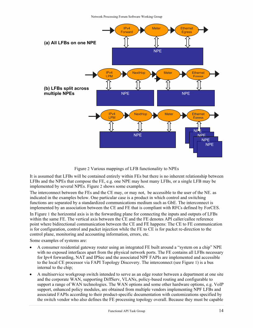
Figure 2 Various mappings of LFB functionality to NPEs
It is assumed that LFBs will be contained entirely within FEs but there is no inherent relationship between LFBs and the NPEs that compose the FE, e.g. one NPE may host many LFBs, or a single LFB may be implemented by several NPEs. Figure 2 shows some examples. The interconnect between the FEs and the CE may, or may not, be accessible to the user of the NE. as indicated in the examples below. One particular case is a product in which control and switching functions are separated by a standardized communications medium such as GbE. The interconnect is implemented by an association between the CE and FE that is compliant with RFCs defined by ForCES. In Figure 1 the horizontal axis is in the forwarding plane for connecting the inputs and outputs of LFBs within the same FE. The vertical axis between the CE and the FE denotes API caller/callee reference point where bidirectional communication between the CE and FE happens: The CE to FE communication is for configuration, control and packet injection while the FE to CE is for packet re-direction to the control plane, monitoring and accounting information, errors, etc. Some examples of systems are: • A consumer residential gateway router using an integrated FE built around a “system on a chip” NPE
with no exposed interfaces apart from the physical network ports. The FE contains all LFBs necessary for Ipv4 forwarding, NAT and IPSec and the associated NPF FAPIs are implemented and accessible to the local CE processor via FAPI Topology Discovery. The interconnect (see Figure 1) is a bus internal to the chip;
• A multiservice workgroup switch intended to serve as an edge router between a department at one site and the corporate WAN, supporting DiffServ, VLANs, policy-based routing and configurable to support a range of WAN technologies. The WAN options and some other hardware options, e.g. VoIP support, enhanced policy modules, are obtained from multiple vendors implementing NPF LFBs and associated FAPIs according to their product-specific documentation with customizations specified by the switch vendor who also defines the FE processing topology overall. Because they must be capable
Functional API Task Group 14

Network Processing Forum Software Working Group
of being installed by users, who may buy them separately, the switch vendor must approve and configure its product CE and FE interfaces to accommodate the customizations and validate the interface suppliers’ FAPI implementations The interconnect is likely to be a backplane, possibly standardized by the NPF. The switch may offer a ForCES compliant function;
• A telecom-grade core switch using separately serviceable commercial off-the-shelf (COTS) hardware and software from many vendors. The components have independent life-cycles and may be exchanged, replaced and varied at any time, possibly years after the switch is commissioned. The switch vendor implements NPF hardware interfaces and messaging specifications in its chassis and switch fabric and relies on 3rd-party products to comply with these and, additionally, to implement NPF service and functional APIs documented to a level sufficient to allow the vendor to adapt the components’ operation to ensure that the switch will adapt to a range of LFB implementations and configurations. The interconnect is likely to be a backplane, possibly standardized by the NPF. The switch may offer a ForCES compliant function;
These three variations include the two extremes: the simplest case, where no LFB detail is required; through an intermediate situation where specific detail and functionality is needed according to an agreed specification where LFB functionality and execution order is predefined; to the most complex where a system can configure itself with very detailed knowledge of LFB composition and function. Of course, there will be many variations on these themes, some of which are shown in Appendix A
Functional API Task Group 15

Network Processing Forum Software Working Group
9 Interoperability of LFBs The FAPI model provides a framework to permit interoperability of LFB implementations, which is achieved through specifying compatible syntax and semantics of information exchanged between them (horizontally), configurable via the NPF FAPI functions (vertically). Beyond citing NPF standardised hardware messaging and transport mechanisms, the model does not explicitly define how the NPEs that execute the LFBs are connected electrically (SPI-3, LA-1, etc), but assumes that they are connected either physically or logically. For a physical interconnect, the model also assumes that there is a need, and a mechanism, for exchanging information between distinct NPEs. For communication between NPEs the mechanism used for this exchange is assumed by the FAPI model to be NPF Messaging. The mechanism used between FEs is also assumed to be NPF Messaging. The FAPI model specifies the interaction of LFBs that reside in the forwarding plane. These LFBs provide interoperability at the level of API functions used to control the underlying chip, or chipset, i.e. NPEs. Providing a common set of API functions that expose the functionality of devices generally found in an FE, allows for simplified integration of control software used to manage these devices. The other purpose the FAPI model serves, by way of LFBs, is to provide interoperability in terms of function, in that a sequenced collection of LFB types will provide a continuous flow of normative packet processing in a FE. This allows for succinct definition of how packet processing will occur, and provides simplified integration of multi-vendor NPEs in the forwarding plane. These two interoperability principles of the FAPI model provide a mechanism for integrating FE functionality into a system, in terms of adding physical capabilities and services. An LFB specification MUST NOT define horizontal interoperability down to a normative level of specific physical interfaces, encoding of PDUs, etc. as these are implementation specific. It should define horizontal interoperability in terms of what types and values of information an LFB expects of another LFB, or what types and values of information an LFB produces. For instance, when the Classifier API implementation sets up filters with rules and metadata tag values that associate packets with the rules that were matched by the classifier those tag values MUST have meanings that downstream LFBs can depend upon. So it is normative to talk about the tag semantics.
Functional API Task Group 16

Network Processing Forum Software Working Group
10 The FE Model The structure of this section is as follows: • Section 10.1 introduces the naming conventions for elements in the FAPI model;; • Section 10.2 explains the difference between a state model and a capability model, how the two can
be combined in the FE model, and how they relate to LFB capability and state; • Section 10.3 introduces the concept of LFBs (Logical Functional Blocks) as the basic functional
building blocks in the FE model; • Section 10.4 discusses the logical inter-connection and ordering between LFB instances within an FE,
that is, the LFB topology.
10.1 Naming of FEs A namespace is used to associate a system-wide unique name, or handle, with each FE. This handle is used by FAPI IAs to select a specific FE when a FAPI function is invoked. Its value is determined by the FE manager module, shelf controller or some other run-time process, or it may be pre-determined by the system architecture.
10.2 State Model and Capability Model for the FE Capability information at the FE level will describe what LFB classes the FE can instantiate; how many instances of each can be created; the topological (i.e., linkage) limitations between these LFB instances, etc., which is different from LFB state and capability. Section 11.6.4 defines the LFB level attributes including capability information. The FE state information can be represented by two levels. The first level is the logically separable and distinctive packet processing functions, (the LFBs). The second level of information is about how these individual LFBs are ordered and placed along the datapath to deliver a complete forwarding plane service. The interconnection and ordering of the LFBs is called the LFB Topology.
10.3 LFB Modeling within the FE Each LFB performs a well-defined action or computation on the packets passing through it. Upon completion of such function, either the packets are modified in certain ways (like a decapsulator, or marker), or some results are generated and stored, probably in the form of metadata (like a classifier). Each LFB typically does one thing and one thing only. Classifiers, shapers, meters are all examples of LFBs. Modeling LFBs at such fine granularity allows us to use a small number of LFBs to create the higher-order FE functions (like IPv4 forwarder) precisely, which in turn can describe more complex networking functions and vendor implementations of software and hardware. Note: the term “LFB class” is used to indicate formally the type of function the LFB performs. This concept is defined in the LFB data modeling section, 11. An LFB has zero or more inputs, each of which takes a packet P, and optionally metadata M; and produces zero or more outputs, each of which carries a packet P', and optionally metadata M'. Metadata is data associated with the packet in the NE (router, switch, etc.) and passed between one LFB to the next, but not sent across the network, (discussed in more detail in section 10.3.5) The inputs, outputs and attributes of the LFB can be queried and manipulated by the CE.
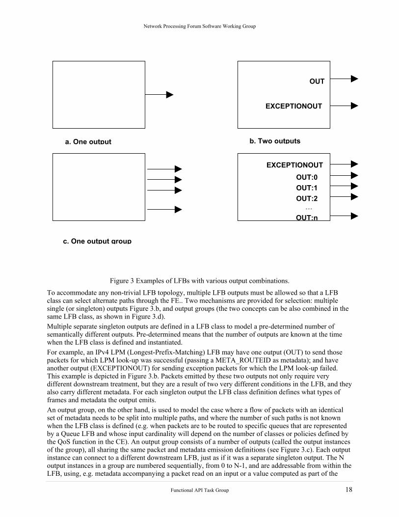
10.3.1 LFB Outputs A LFB output is a conceptual port on a LFB that can send information to some other LFB. The information is typically a packet and associated metadata, although in some cases it might consist of only metadata, i.e. with no packet data, for example to communicate events between LFBs. A single LFB output can be connected to only one LFB input. This is required to make the packet flow through the LFB topology unambiguous. Thus if forking, joining, duplication and selection occur, these are defined by specific LFBs. Some LFBs will have a single output, as depicted in Figure 3.a.
Functional API Task Group 17
Network Processing Forum Software Working Group
OUT
EXCEPTIONOUT
b. Two outputs a. One output
EXCEPTIONOUTOUT:0 OUT:1 OUT:2
…OUT:n
c. One output group
Figure 3 Examples of LFBs with various output combinations.
To accommodate any non-trivial LFB topology, multiple LFB outputs must be allowed so that a LFB class can select alternate paths through the FE.. Two mechanisms are provided for selection: multiple single (or singleton) outputs Figure 3.b, and output groups (the two concepts can be also combined in the same LFB class, as shown in Figure 3.d). Multiple separate singleton outputs are defined in a LFB class to model a pre-determined number of semantically different outputs. Pre-determined means that the number of outputs are known at the time when the LFB class is defined and instantiated. For example, an IPv4 LPM (Longest-Prefix-Matching) LFB may have one output (OUT) to send those packets for which LPM look-up was successful (passing a META_ROUTEID as metadata); and have another output (EXCEPTIONOUT) for sending exception packets for which the LPM look-up failed. This example is depicted in Figure 3.b. Packets emitted by these two outputs not only require very different downstream treatment, but they are a result of two very different conditions in the LFB, and they also carry different metadata. For each singleton output the LFB class definition defines what types of frames and metadata the output emits. An output group, on the other hand, is used to model the case where a flow of packets with an identical set of metadata needs to be split into multiple paths, and where the number of such paths is not known when the LFB class is defined (e.g. when packets are to be routed to specific queues that are represented by a Queue LFB and whose input cardinality will depend on the number of classes or policies defined by the QoS function in the CE). An output group consists of a number of outputs (called the output instances of the group), all sharing the same packet and metadata emission definitions (see Figure 3.c). Each output instance can connect to a different downstream LFB, just as if it was a separate singleton output. The N output instances in a group are numbered sequentially, from 0 to N-1, and are addressable from within the LFB, using, e.g. metadata accompanying a packet read on an input or a value computed as part of the
Functional API Task Group 18

Network Processing Forum Software Working Group
LFB’s function. The LFB thus has a built-in mechanism to select exactly one specific output instance for each packet. This mechanism MUST be described in the textual definition of the LFB class and it is typically configurable via some attributes of the LFB. But, for dynamically configurable FEs and in contrast with the singleton outputs, the number of output instances can be different from one instance of the LFB class to another. The class definition MAY include a lower and/or an upper limit on the number of output instances of the group. In addition, for configurable FEs, the FE capability information MAY include further limits on the number of instances in specific output groups of certain LFBs. The actual number of output instances in a group is an attribute of the LFB instance, which is read-only for static topologies, and read-write for dynamic topologies. For example, consider a re-director LFB, whose sole purpose is to direct packets to one of N downstream paths based on one of the metadata tag values associated with each arriving packet. The need for such an LFB arises fairly frequently, for example to divide the data path into an IPv4 and an IPv6 path based on a FRAMETYPE metadata (N=2), or to fork into color specific paths after metering using the COLOR metadata (red, yellow, green; N=3), etc. The metadata which is to be used as a selector for the output instance is a property of the LFB class. For each packet the value of the specified metadata may be used as a direct index to the output instance. Alternatively, the re-director LFB may have a configurable selector table that maps a metadata value to an output instance. Note that in principle other LFB classes may also use output groups to build in similar adaptive forking capability. For example, a classifier LFB with one input and N outputs can be defined by using the output group concept. Alternatively, a classifier LFB with one singleton output in combination with an explicit N-output re-director LFB can be used to model the same processing behavior. The decision of whether to use the output group model for a certain LFB class is left to the LFB class designers. Important Note: The NPF FAPI model, while accepting the principles of the output group concept as a model for future use by LFBs in general, imposes the additional working constraint that one LFB type only, the re-director, may use output groups. The model also allows in principle the output group to be combined with other singleton output(s) in the same class, as is demonstrated in Figure 3.d. The LFB here has two types of outputs, OUT for normal packet output, and EXCEPTIONOUT for packets that triggered some exception. The normal output, OUT, has multiple instances, i.e., it is an output group.
10.3.2 LFB Inputs A LFB input is a conceptual port on a LFB where the LFB can receive information from other LFBs. The information is typically a packet and associated metadata, although in some cases it might consist of only metadata, i.e., with no packet data, for example to communicate events between LFBs. It is generally the case that there will be LFB instances that will receive packets from more than one other LFB instance (fan-in). There are three ways of modeling the fan-in, effectively multiplexing them at the conceptual portl: * Implicit multiplexing via a single input (Figure 4.a); * Explicit multiplexing via multiple singleton inputs (Figure 4.b); * Explicit multiplexing via a group of inputs (input group), (Figure 4.c); The above modes can be combined in the same LFB. The simplest form of multiplexing uses a singleton input (Figure 4.a). Typically, most LFBs will have only one (singleton) input. Multiplexing into a single input is possible because the model allows for more than one LFB output to connect to the same input of an LFB. Note: as detailed above, outputs cannot be connected to more than one input. Multiplexing into a single input is applicable when the packets from the upstream LFBs are similar (in frame-type and accompanying metadata) and require similar processing. Obviously, this representation has no implications on the arrival time of packets and metadata at the input. The second method of modeling fan-in uses separately defined singleton inputs (Figure 4.b). This model is meant for situations where the LFB needs to handle distinct types of packet streams, requiring input-specific handling inside the LFB, and where the number of such distinct cases is an inherent property of the LFB class (and hence is known when the LFB class is defined). For example, a Layer 2 Decapsulation/Encapsulation LFB may have two inputs, one for receiving Layer 2 frames for
Functional API Task Group 19

Network Processing Forum Software Working Group
decapsulation, and one for receiving Layer 3 frames for encapsulation. Such a LFB would expect very different frames (L2 vs. L3) at its inputs, each with different sets of metadata, and would obviously apply different processing on frames arriving at these inputs.
LFB X
LFB Y Input
Meter LFBLFB Z
a. Fan-in using a singleton input
LFB X Layer 2LFB
Layer 3LFB Y
b. Multiple inputs
Queue LFB: 0 IN:0 678 Input group Queue LFB: 1 IN:n
…
Queue LFB: N
c. Using an input group to multiplex inputs
Figure 4 Input modeling concepts (examples).
The third method of modeling fan-in uses the concept of an input group. The concept is similar to the output group introduced in the previous section, and is depicted in Figure 4.c. An input group consists of a number of input instances, all sharing the properties (same packet framing and metadata). The N input instances are numbered from 0 to N-1. From the outside these inputs appear as normal inputs, i.e., any compatible upstream LFB can connect its output to one of these inputs. When a packet is presented to the LFB at a particular input instance, the index of the input where the packet arrived will be known to the LFB and this information may be used as metadata in the internal processing. For example, the input index can be used as a table selector, or as an explicit precedence selector to resolve contentions. As with output groups, the number of input instances in an input group is not defined in the LFB class, though the class definition may include restrictions on the range of possible values. In addition, if a FE supports configurable topologies, it may impose further limitations on the number of instances for a particular input group(s) of a particular LFB class. Within these limitations, different instances of the same class may have a different number of input instances. The number of actual input instances in the group is an attribute of the LFB class, which is read-only for static topologies, and it is read-write for configurable topologies.
Functional API Task Group 20

Network Processing Forum Software Working Group
As an example for the input group, consider the Scheduler LFB depicted in Figure 4.c. Such an LFB receives packets from a number of Queue LFBs via a number of input instances, and may use the input index information to control contention resolution and scheduling. Important Note: The NPF FAPI model imposes the additional constraint that only one LFB type, the multiplexer LFB as shown in Figure 4(c), may use the input group feature. Data supplied to the LFB inputs in the group must be forwarded on the output with additional metadata that encodes the input index within the group on which the data was received. LFBs that implement this function will include multiplexers and aggregator functions.
10.3.3 Paired LFBs: LFB Messaging Interfaces and Models of Physical Interfaces The above scenarios for LFB inputs and outputs do not include the cases where messages flow across LFB interfaces to, or from, similar interfaces outside the FE in which the originating or receiving LFB is located. This case arises in particular for LFB Messaging blocks and LFBs that model physical media interfaces. These are termed “paired blocks”. Where present these are representable in the topology using the approaches described in Figure 5.
Ingress ports
Egress ports
Ingress
Forwarding path LFB instances
Egress
Port
Forwarding path LFB instances
(a) Port LFB appears as single LFB Instance
Type T, instance ID X
Type T, instance ID Z
Type T, instance ID Y
(b) Port LFB appears as separate LFB Instances of the same type
Figure 5 Representation of paired blocks
The figure shows an example applying to media interfaces but it can be applied to other similar cases, including the Messaging LFB specification, [MESSLFB]. In Figure 5.a a single block instantiated as instance ID X of type T, is used containing all the functionality associated with the medium interface.
Functional API Task Group 21
Network Processing Forum Software Working Group
This is recommended because it is closest to reality, especially where ingress and egress processes are closely coupled as they are in IEEE 802.11 for example. Alternatively, using a representation that more closely reflects the packet processing steps, the approach shown in Figure 5.b can be used. In this case there are two LFB instances of the same type T but with different instance IDs, Y and Z. The Topology Discovery functions MUST be capable of returning a representation of the topology that allows either approach but the one used in a specific FE is an implementation decision.
10.3.4 Packet Type When LFB classes are defined, the input and output packet formats (e.g., IPv4, IPv6, Ethernet, etc.) MUST be specified: these are the types of packets a given LFB input is capable of receiving and processing, or a given LFB output is capable of producing. This requires that distinct frame types be uniquely labeled with a symbolic name and/or ID. The values of these format identifiers may be standardized by the NPF in a separate IA.
10.3.5 Metadata – the Transfer of State of LFBs and Packets between LFBs As described above, the operation of the FE is logically decomposed into a set of LFBs and is modeled by a directed graph of such LFBs. To make the decomposition possible, the model requires per-packet state variables that, together, maintain the overall state of the FE consistently. Note, however, that the LFB model may or may not closely resemble the physical implementation, hence the per-packet state variables of the model may differ from the actual per-packet state variables of the physical implementation. Per-packet state and the life-cycle of per-packet state variables in the FE are the key considerations in specifying the metadata model. 10.3.5.1 Per-packet state variables and their life-cycle As the packet is processed in the FE, various types of state information are created and kept in association with the packet to assist further processing of the packet. Although the representation of such state information is implementation dependent, it can always be regarded as a collection of state variables. The interface port at which the packet was received, the result of a classification operation, the color associated with the packet as a result of metering, etc., are all examples of such per-packet state variables. For most cases, each of these variables can be conveniently modeled as a <label, value> pair, where the label identifies the type of information (for example, "color"), and its value holds the current value for the packet (e.g., "red"). The value is typically a simple integer (enumerator, table entry reference, actual protocol value), or in some cases it may be some structured protocol address, such as an IP or MAC address. In any given system, there is a number of state variables that can be associated with (and are created for) a packet. As the packet goes through its life-cycle (i.e., traverses through the FE), each of the state variables goes through its own life-cycle, some possibly more than once. For the discussion that follows, we define the life-cycle of the state variable using three types of events: "write", "read" and "consume". The first "write" event initializes the value of the variable (implicitly creating and/or initializing the variable), and hence starts the life-cycle. The explicit "consume" event terminates the life-cycle and the variable is destroyed. Within the life-cycle, that is after a "write" event but before the next "consume" event, there can be an arbitrary number of "write" and "read" events. These can be mixed in an arbitrary order within the life-cycle. Outside the life-cycle, that is before the first "write" event, or after the “consume" event, the state variable is non-existent or non-initialized. Reading a state variable outside its life-cycle is considered an error. Although the length of the life-cycle of a state variable may coincide with the packet's own life-cycle, typically it is much shorter, and sometimes it is possible that a state variable goes through more than one life-cycle for the same packet. An example for the latter is when an IP packet is encapsulated (tunneled) in another IP packet (e.g., GRE or IP-IP). In such a case, IP LPM lookup needs to be done twice, once for the inner packet and then for the outer. Assuming that the LPM lookup results in a state variable that encodes the next hop information which is then used and consumed by a next hop stage, such a state variable is initialized and then consumed twice, i.e., goes through two life-cycles.
Functional API Task Group 22

Network Processing Forum Software Working Group
10.3.5.2 Per-packet State Variables and the LFB Model With respect to the life-cycle of per-packet state variables in the LFB model, we can distinguish between intra-LFB state variables and inter-LFB state variables. The former type are state variables that have life-cycles that are completely contained within an LFB. The existence and actual value of such variables do not need to be (and should not be) exposed outside the LFB, except that they may be mentioned in the textual operational description of the LFB as a way of describing the logical operation of the LFB. Inter-LFB, per-packet, state variables of the model that have life-cycles spanning more than one LFB are the ones that will be carried as metadata. Inter-LFB state variables MUST be exposed outside the respective LFBs, as they put certain requirements on both producer and consumer LFBs for ensuring interoperability. One example of packet metadata is the flowId used for basic IPv4 forwarding purposes. Imagine two LFBs connected to each other, where the first block performs a longest prefix match on a packet, associating a flowID with each packet, and the second LFB uses the flowID to determine the layer 2 encapsulation, including DMAC, to perform on a packet. The second block in this case includes next hop resolution of the packet, and as such is configured by the routing application (via the IPv4 service APIs, which in turn would call the functional API of the two blocks mentioned here to set up the data in the resource tables). In this example it is necessary to be able to specify the prefix --> flowID mapping that the first block will perform on each packet, and to specify the flowID --> DMAC mapping the second block needs to appropriately encapsulate packets. 10.3.5.3 The Metadata Model The per-packet inter-LFB state information is propagated with the packet as metadata. The model does not specify how the metadata is actually passed (the framing in a message or the registers of an NPE), it simply assumes that the metadata is passed with the packet. The only exception is inter-FE links, where physical inter-operability requires that the frame formats, metadata encoding, endian-ness, etc., are properly specified. Such topics are described in the Messaging LFB specification [[MESSLFB]]. A metadatum corresponds to one per-packet state variable, and thus has a label (or tag) part that identifies the type of information, and a value part that carries the actual information. For the purposes of discussion, denote this as a <TAG="value"> pair, e.g., <COLOR="green">. The tag here is shown as a textual label, but it can be replaced or associated with a unique numeric value (identifier). Also for purposes of discussion, we propose that the value part is assumed to be a 32-bit signed integer with negative values typically used to encode special values. At any given edge of the LFB topology graph (any link between two LFBs), the packet is marked with a finite set of active metadata, where active means that all metadata is inside its life-cycle (i.e., have been properly initialized, and has not been consumed yet). There are two corollaries of this model: • No uninitialized metadata exists in the LFBs in the LFB topology and • There can only be up to one occurrence of each metadata type (label) associated with the packet at
any given time. When the packet is processed by an LFB, i.e., between the point when it is received and the point when it is forwarded by the LFB, the LFB may perform the following operations on any of the metadata: • PROPAGATE: ignores and forwards it • READ: reads and forwards it • RE-WRITE: reads, over-writes and forwards it • WRITE: writes, creating the metadatum if it does not exist already, and forwards it • READ-AND-CONSUME: reads and consumes it • CONSUME: consumes it (without reading) The last two terminate the life-cycle of the metadata, meaning that the metadata is not forwarded with the packet when the packet is sent to the next LFB.
Functional API Task Group 23

Network Processing Forum Software Working Group
New metadata is generated by an LFB when the LFB applies a WRITE to a metadata type that was not present when the packet was received by the LFB. The LFB may apply the WRITE operation without knowing or caring if the given metadata existed or not. If it existed, it gets over-written; if it did not exist, it gets created. Note: • For source type LFBs (i.e., that insert packets into the FE), WRITE is the only meaningful metadata
operation. • Sink type LFBs (that remove the packet from the FE) may either read (READ-AND-CONSUME) or
ignore (this is effectively CONSUME) each metadata. 10.3.5.4 Metadata Production and Consumption Note: we use the term “consume” and “consumer” to refer to the user of metadata and what it does with metadata, which may mean CONSUME and/or READ according to the specific user’s functions. For a given metadatum on a given packet path, there MUST be at least one LFB that creates that metadata (producer). There may be no readers or consumer of the metadatum. The producer and the consumer LFBs need not necessarily be adjacent. There may be multiple consumers for the same metadata. There may be multiple producers of the same metadata. If a packet path involves multiple producers of the same metadata, then the 2nd, 3rd, etc. producers overwrite the metadata value. The LFB class definition will specify what metadata that is produced by an LFB and the outputs that it are associated with it.A producer may always generate the metadata on the output, or may generate it only upon certain conditions. We call the former "unconditional" metadata, whereas the latter is "conditional" metadata. In the case of conditional metadata, it MUST be possible to determine from the definition of the LFB when "conditional" metadata is produced. The consumer, or reader, behavior of an LFB, i.e., what metadata the LFB needs for its operation, is defined in the LFB class definition on a per input basis. An input may "require" a given metadatum, or may treat it as "optional" information. In the latter case it MUST be explicitly defined in the LFB class definition what happens if an optional metadata is not provided. This may be done in the form of providing a default value for each optional metadata, and assuming that the default value is substituted (including written and created) if the metadata is not provided for a packet. 10.3.5.5 Expressing Inter-LFB Metadata Dependencies When a consumer LFB requires a given metadatum, it has dependencies on its up-stream LFBs, that is, it can only function if there is at least one producer of that metadata and no intermediate LFB consumes the metadata. The model provides the framework for implementers to expose the inter-dependency, so that the inter-dependency can be taken into consideration when constructing LFB topologies, and also that dependency can be verified when validating topologies. For extensibility reasons it is preferred that an LFB specification defines what metadata the LFB requires, but without specifying from what other LFB it expects a certain metadatum to come from. Similarly, LFBs MUST specify what metadata they produce, but without defining what other LFBs the metadata is meant for, except by illustrative example. When specifying the metadata tags (labels), producer LFB(-class) MUST use the same tag as its intended consumer(s), or vice versa. Note: the LFB Template definition guidelines [LFBTEMPLATE] provide a procedure for expressing these interdependencies. The use of illustrative examples is encouraged. 10.3.5.6 Fixed Tag, Variable Tag, and Configurable Tag Metadata Production When the produced metadata is defined for a given LFB class, most metadata will be specified with a fixed tag. For example, a Rate Meter LFB will always produce the "Color" metadata. Some LFBs MAY have the capability to produce one or more of their metadata with tags that are not fixed in the LFB class definition, but instead can be selected per LFB instance. We call this variable tag metadata production. If an LFB produces metadata with variable tag, a corresponding LFB attribute--called the tag selector--specifies the tag for each such metadata. This mechanism is to improve the
Functional API Task Group 24

Network Processing Forum Software Working Group
versatility of certain multi-purpose LFB classes, since it allows the same LFB class be used in different topologies, producing the right metadata tags according to the needs of the topology. An example for such LFB class is a Generic Classifier LFB. Depending on the capability of the FE, the tag selector can be a read-only or a read-write attribute. In the former case the tag cannot be modified by the CE. In the latter case the tag can be configured by the CE, hence we call this "configurable tag metadata production." (Note that in this definition configurable tag metadata production is a subset of variable tag metadata production.) As for any other LFB attribute, the FAPI for the respective LFB will provide access for the CE to examine (and for the configurable case to modify) the value of the tag selector. 10.3.5.7 Fixed Tag, Variable Tag, and Configurable Tag Metadata Needs Most LFB classes will specify their metadata needs using fixed metadata tags. For example, a Next Hop LFB may always require a "NextHopId" metadata. For a small subset of LFB classes, however, it is beneficial to leave the tag of some required or optional metadata unspecified in the LFB class definition, and instead refer to an LFB attribute that provides the required metadata tag at run-time. For example, the Redirector LFB may need to use a "ClassID" metadata in one instance, and a "ProtocolType" metadata in another instance as a basis for selecting the right output port. This mechanism allows for a certain level of adaptability for the LFB class. The metadata tag selector attribute may be read-only or read-write, depending on the capabilities of the LFB instance and the FE. In either case, the FAPI for the respective LFB will provide the means for accessing the attribute. 10.3.5.8 Metadata Usage Categories Depending on the role and usage of a metadatum, various amounts of encoding information must be provided when the metadata is defined, and some cases offer less flexibility in the value selection than others. As far as usage of a metadatum is concerned, three types of metadata exist: • Relational (or binding) metadata • Enumerated metadata • Explicit/external value metadata
10.3.5.8.1 Relational (Binding) Metadata The purpose of the relational metadata is to refer in one LFB instance (producer LFB) to information (an object or some other item of data) in another downstream LFB instance (consumer LFB), where the information is typically an entry in a table attribute of the consumer LFB. For example, the Prefix Lookup LFB executes an LPM search using its prefix table and resolves to a next-hop reference. This reference needs to be passed as metadata by the Prefix Lookup LFB (producer) to the Next Hop LFB (consumer), and must refer to a specific entry in the next-hop table within the consumer. Expressing and propagating such binding relationship is probably the most common usage of metadata. One or more objects in the producer LFB are related (bound) to a specific object in the consumer LFB. Such relation is established by the CE very explicitly, i.e., by properly configuring the attributes in both LFBs. Available methods include the following: • Tagging the involved objects in both LFBs by the same unique (but otherwise arbitrary) identifier.
The value of the tag is explicitly configured (written by the CE) into both LFBs, and this value also is the value that the metadata carries between the LFBs.
• Using a naturally occurring unique identifier of the consumer's object (for example, the array index of a table entry) is used as a reference (and as a value of the metadata. In such case the index is obtained (read) or inferred by the CE by communicating with the consumer LFB. Once the CE obtained the index, it needs to plug (write) it into the producer LFB to establish the binding.
Important characteristics of the binding usage of metadata are:
Functional API Task Group 25

Network Processing Forum Software Working Group
• The value of the metadata appears in the FAPI for BOTH the consumer and the producer. Using the tagging technique, the value is WRITTEN to both LFBs. Using the other technique, the value is WRITTEN to only the producer LFB and may be READ from the consumer LFB.
• The actual value is irrelevant for the CE, the binding is simply expressed by using the SAME value at the consumer and producer LFBs.
• Hence the definition of the metadata type does not have to include value assignments. The only exception is when some special value(s) of the metadata must be reserved to convey special events. Even though such special cases must be then defined with the metadata specification, their encoded values can be selected rather arbitrarily. For example, for the above Prefix Lookup LFB example, a special value may be reserved to signal the NO-MATCH case, and the value of zero may be assigned for this purpose.
10.3.5.8.2 Enumerated Metadata An example is the Color metadata that is produced by a Meter LFB and consumed by some other LFBs. As the name suggests, such metadata has a number of possible discrete values, each with a very specific meaning. All the possible cases must be enumerated when defining such a metadata type. Although a value encoding must be included in the specification, the actual values can be selected rather arbitrarily (e.g., <Red=0, Yellow=1, Green=2> and <Red=3, Yellow=2, Green 1> would be both valid encodings, what is important is that an encoding is specified). The value of the enumerated metadata may or may not be conveyed at the FAPI interface between the CE and FE.
10.3.5.8.3 Explicit/External Value metadata This refers to cases where the value of the metadata is explicitly used by the consumer LFB to change some packet header fields. In other words, its value has a direct and explicit impact on some packet field and will be visible externally when the packet leaves the NE. Examples are TTL increment given to a Header Modifier LFB, DSCP value for a Remarker LFB. For this type of metadata not only the value, but also the encoding must be explicitly provided in the metadata definition, the values cannot be selected arbitrarily, but rather they should conform to what is commonly expected. For example, a TTL increment metadata should encode with 0 the no increment case, by 1 the single increment case, etc. A DSCP metadata should use 0 to encode DSCP=0, 1 to encode DSCP=1, etc.
10.3.5.9 LFB Versioning LFB class versioning is supported by requiring a version string in the class definition. CEs may support backwards compatibility between multiple versions of a particular LFB class, but FEs are not allowed to support more than one single version of a particular class. 10.3.5.10 LFB Inheritance LFB class inheritance is supported in the FE model as a means of defining new LFB classes. This also allows FE vendors to add vendor-specific extensions to standardized LFBs. An LFB class specification MUST specify the base class (with version number) it inherits from (with the default being the base LFB class). Multiple-inheritance is not allowed, though, to avoid unnecessary complexity. Note: although the specification of the base-class is obligatory, it has no formal meaning in this version of the FAPI model, (e.g. it is not used by a compiler) and can thus be considered as a means of documenting a relationship with a logical class hierarchy. Inheritance should be used only when there is significant reuse of the base LFB class definition. A separate LFB class should be defined if there is not enough reuse between the derived and the base LFB class. An interesting issue related to class inheritance is backward compatibility (between a descendant and an ancestor class). Consider the following hypothetical scenario where there exists a standardized LFB class "L1". Vendor A builds an FE that implements LFB "L1" and vendor B builds a CE that can recognize and operate on LFB "L1". Suppose that a new LFB class, "L2", is defined based on the existing "L1" class (for example, by extending its capabilities in some incremental way). Lets first examine the FE backward
Functional API Task Group 26

Network Processing Forum Software Working Group
compatibility issue by considering what would happen if vendor A upgrades its FE from "L1" to "L2" while vendor B's CE is not changed. The old L1-based CE can interoperate with the new L2-based FE if the derived LFB class "L2" is indeed backward compatible with the base class "L1". The reverse scenario is a much less problematic case, i.e., when CE vendor B upgrades to the new LFB class "L2", but the FE is not upgraded. Therefore in this example, the CE must only call the LFB L1 functions when programming this LFB on this FE. Note that as long as the CE is capable of working with older LFB classes, this problem does not affect the model; hence we will use the term "backward compatibility" to refer to the first scenario concerning FE backward compatibility. Inheritance can be designed into the model with backward compatibility support by constraining the LFB inheritance such that the derived class is always a functional superset of the base class, i.e., the derived class can only grow on top of the base class, but not shrink from it. Additionally, the following mechanisms are required to support FE backward compatibility: • When detecting an LFB instance of an LFB type that is unknown to the CE, the LFB definition
SHOULD provide a way for the CP to query the base class of such an LFB from the FE. • The LFB instance on the FE SHOULD support a backward compatibility mode (meaning the LFB
instance reverts itself back to the base class instance), and the LFB definition SHOULD provide a way for the CP to configure the LFB to run in such mode.
10.4 FE Datapath Modeling – LFB Topology and Usage Guidelines Packets coming into the FE from ingress ports generally flow through multiple LFBs before leaving out of the egress ports. How an FE treats a packet depends on many factors, such as type of the packet (e.g., IPv4, IPv6 or MPLS), actual header values, time of arrival, etc. The result of the operation of an LFB may have an impact on how the packet is to be treated in further (downstream) LFBs and this differentiation of packet treatment downstream can be conceptualized as having alternative datapaths in the FE. For example, the result of a 6-tuple classification (performed by a classifier LFB) controls what rate meter is applied to the packet (by a rate meter LFB) in a later stage in the datapath. The LFB topology is a directed graph representation of the logical datapaths within an FE, with the nodes representing the LFB instances and the directed link the packet flow direction from one LFB to the next. Section 10.4.1discusses how the FE datapaths can be modeled as LFB topology; while Section 10.4.2 focuses on issues around LFB topology reconfiguration.
10.4.1 Alternative Approaches for Modeling FE Datapaths There are two basic ways to express the differentiation in packet treatment within an FE, one representing the datapath directly and graphically (topological approach) and the other utilizing metadata (the encoded state approach). • Topological Approach - using this approach, differential packet treatment is expressed via actually
splitting the LFB topology into alternative paths. In other words, if the result of an LFB must control how the packet is further processed, then such an LFB will have separate output ports (one for each alternative treatment) connected to separate sub-graphs (each expressing the respective treatment downstream).
• Encoded State Approach - an alternative way of expressing differential treatment is using metadata. The result of the operation of an LFB can be encoded in a metadata which is passed along with the packet to downstream LFBs. A downstream LFB, in turn, can use the metadata (and its value, e.g., as an index into some table) to decide how to treat the packet.
Theoretically, the two approaches can substitute for each other, so one may consider using purely one (or the other) approach to describe all datapaths in an FE. However, neither model by itself is very useful for practically relevant cases. For a given FE with certain logical datapaths, applying the two different modeling approaches would result in very different looking LFB topology graphs. A model using purely the topological approach may require a very large graph with many links (i.e., paths) and nodes (i.e., LFB instances) to express all alternative datapaths. On the other hand, a model using purely the encoded state model would be restricted to a string of LFBs, which would make it very unintuitive to describe very different datapaths (such as MPLS and IPv4). Therefore, a mix of these two approaches will likely be
Functional API Task Group 27

Network Processing Forum Software Working Group
used for a practical model. In fact, as we illustrate it below, the two approaches can be mixed even within the same LFB. In principle, the two approaches can be used interchangeably.In practice, however, most FEs will be modeled using a mixture of the two, achieving a balance between differentiation of processing by topology (e.g. making it clear that MPLS follows a different path from IPv4) and encoded state. For example, consider a classifier with N classification outputs followed by some other LFBs, Figure 6(a) shows what the LFB topology looks like by using the purely topological approach. Each output from the classifier goes to one of the N LFBs followed and no metadata is needed here. The topological approach is simple, straightforward and graphically intuitive. However, if N is large and the N nodes following the classifier (LFB#1, LFB#2, ..., LFB#N) all belong to the same LFB type (for example, meter) but each with its own independent attributes, the encoded state approach gives a much simpler topology representation, as shown in Figure 6(b). The encoded state approach requires that a table of N rows of meter attributes is provided in the Meter node itself, with each row representing the attributes for one meter instance. A metadata M is also needed to pass along with the packet P from the classifier to the meter, so that the meter can use M as a look-up key (index) to find the corresponding row of the attributes that should be used for any particular packet P. Now what if all the N nodes (LFB#1, LFB#2, ..., LFB#N) are not of the same type? For example, if LFB#1 is a queue while the rest are all meters, what is the best way to represent such datapaths? While it is still possible to use either the pure topological approach or the pure encoded state approach, the natural combination of the two seems the best by representing the two different functional datapaths using topological approach while leaving the N-1 meter instances distinguished by metadata only, as shown in Figure 6(c).
P LFB#1 (Attrib – 1)
P12
Classifier 3…N
P
(a) Using pure topological approach
Functional API Task Group 28

Network Processing Forum Software Working Group
Meter(Attrib – 1)(Attrib – 2)
(Attrib – N)
12
Redirector 3…N
(b) Using pure encoded state approach to represent the LFB topology in 5(a), if LFB#1, LFB#2, and LFB#N are of the same type (e.g., meter)
Queue (Attrib – 2)
P, M12
Redirector 3…N
Meter (Attrib – 1)(Attrib – N)
(c) Using a combination of the two, if LFB#1, LFB#2, ..., and LFB#N are of different types (e.g., queue and meter)
Figure 6 Illustrations of the use of the Topology and Encoded State Models
From this example, we demonstrate that each approach has distinct advantage for different situations. Using the encoded state approach, fewer connections are typically needed between a fan-out node and its next LFB instances of the same type, because each packet carries metadata with it so that the following nodes can interpret and hence invoke a different packet treatment. For those cases, a pure topological approach forces one to build elaborate graphs with a lot more connections and often results in an unwieldy graph. On the other hand, a topological approach is intuitive and most useful for representing functionally very different datapaths. For complex topologies, a combination of the two is the most useful and flexible. Here we provide a general design guideline as to what approach is best used for what situation. The topological approach should primarily be used when the packet datapath forks into areas with distinct LFB classes (not just distinct parameterizations of the same LFB classes), and when the fan-outs do not require changes (adding/removing LFB outputs) at all or require only very infrequent changes. Configuration information that needs to change frequently should preferably be expressed by the internal attributes of one or more LFBs (and hence using the encoded state approach).
Functional API Task Group 29
Network Processing Forum Software Working Group
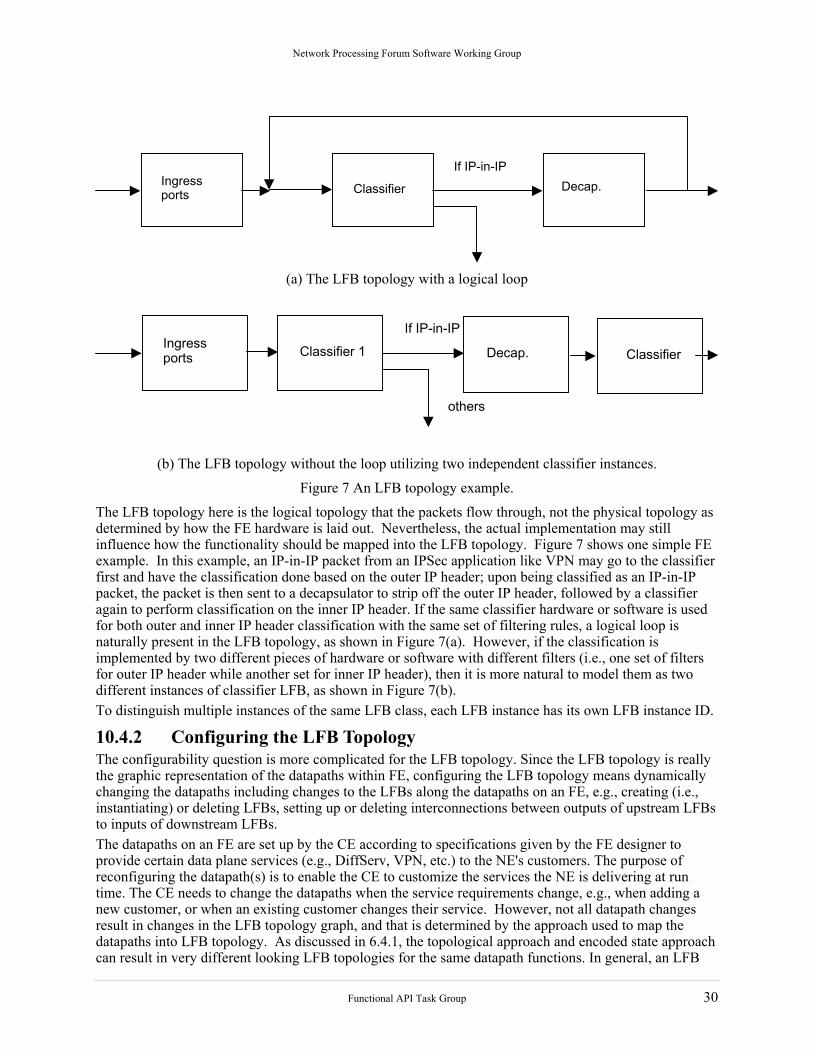
Ingress ports Classifier Decap.
If IP-in-IP
(a) The LFB topology with a logical loop
Ingress ports Classifier 1 Decap.
If IP-in-IP
Classifier
others
(b) The LFB topology without the loop utilizing two independent classifier instances.
Figure 7 An LFB topology example.
The LFB topology here is the logical topology that the packets flow through, not the physical topology as determined by how the FE hardware is laid out. Nevertheless, the actual implementation may still influence how the functionality should be mapped into the LFB topology. Figure 7 shows one simple FE example. In this example, an IP-in-IP packet from an IPSec application like VPN may go to the classifier first and have the classification done based on the outer IP header; upon being classified as an IP-in-IP packet, the packet is then sent to a decapsulator to strip off the outer IP header, followed by a classifier again to perform classification on the inner IP header. If the same classifier hardware or software is used for both outer and inner IP header classification with the same set of filtering rules, a logical loop is naturally present in the LFB topology, as shown in Figure 7(a). However, if the classification is implemented by two different pieces of hardware or software with different filters (i.e., one set of filters for outer IP header while another set for inner IP header), then it is more natural to model them as two different instances of classifier LFB, as shown in Figure 7(b). To distinguish multiple instances of the same LFB class, each LFB instance has its own LFB instance ID.
10.4.2 Configuring the LFB Topology The configurability question is more complicated for the LFB topology. Since the LFB topology is really the graphic representation of the datapaths within FE, configuring the LFB topology means dynamically changing the datapaths including changes to the LFBs along the datapaths on an FE, e.g., creating (i.e., instantiating) or deleting LFBs, setting up or deleting interconnections between outputs of upstream LFBs to inputs of downstream LFBs. The datapaths on an FE are set up by the CE according to specifications given by the FE designer to provide certain data plane services (e.g., DiffServ, VPN, etc.) to the NE's customers. The purpose of reconfiguring the datapath(s) is to enable the CE to customize the services the NE is delivering at run time. The CE needs to change the datapaths when the service requirements change, e.g., when adding a new customer, or when an existing customer changes their service. However, not all datapath changes result in changes in the LFB topology graph, and that is determined by the approach used to map the datapaths into LFB topology. As discussed in 6.4.1, the topological approach and encoded state approach can result in very different looking LFB topologies for the same datapath functions. In general, an LFB
Functional API Task Group 30

Network Processing Forum Software Working Group
topology based on a pure topological approach is likely to experience more frequent topology reconfiguration than one based on an encoded state approach. However, even an LFB topology based entirely on an encoded state approach may have to change the topology at times, for example, to totally bypass some LFBs or insert new LFBs. Since a mix of these two approaches is used to model the datapaths, LFB topology reconfiguration is considered an important aspect of the FE model. Allowing a configurable LFB topology in the FE model does not mandate that all FEs must have such capability. Even if an FE supports configurable LFB topology, it is expected that there will be FE-specific limitations on what can actually be configured. Performance-optimized hardware implementation may have zero or very limited configurability, while FE implementations running on network processors may provide more flexibility and configurability. It is entirely up to the FE designers to decide whether or not the FE actually implements such reconfiguration and how much. It could be a manual change, e.g. a simple runtime switch to enable or disable (i.e., bypass) certain LFBs, or it could be more flexible software reconfiguration: this is all implementation detail internal to the FE and implemented by processes and mechanisms outside the scope of the FE model. In either case, the CE(s) must be able to learn the FE's configuration capabilities. Therefore, the FE model must provide a mechanism for describing the LFB topology configuration capabilities of an FE, (see Section 10 for details): For example: • How many instances of the same class or any class can be created on any given branch of the graph? • Ordering restrictions on LFBs (e.g., any instance of LFB class A must be always downstream of any
instance of LFB class B). Even if the CE is allowed to configure LFB topology for an FE, how can the CE interpret an arbitrary LFB topology (presented to the CE by the FE) and know what to do with it? In other words how does the CE know the mapping between an LFB topology and a particular NE service or application (e.g., VPN, DiffServ, etc.)? First it is unlikely that an FE can support any arbitrary LFB topology; secondly, once the CE understands the coarse capability of an FE, it is up to the CE to configure the LFB topology according to the network service the NE is supposed to provide. So the more important mapping that the CE has to understand is from the high level NE service to a specific LFB topology, not the other way around. We do not expect that the CE has the ultimate intelligence to translate any high level service policy into the configuration data for the FEs, but it is conceivable that within a given network service domain (like DiffServ), a certain amount of intelligence can be programmed into the CE such that the CE has a general understanding of the LFBs involved and so the translation from a high level service policy to the low level FE configuration can be done automatically. Such algorithms are implementation dependent and are outside the scope of the model.
Functional API Task Group 31

Network Processing Forum Software Working Group
Forwarder
Dropper MarkerMeter
Classifier chipIngress
Egress
Scheduler Queue Counter
Network
(a) The Capability of the FE, reported to the CE
A Queue1
Queue2
B Meter1
DropperClassifier
Scheduler
(b) One LFB topology as configured by the CE and accepted by the FE
Functional API Task Group 32

Network Processing Forum Software Working Group
Queue1
AB
Meter1
IPv4 Forwarder Counter1 Dropper1 Queue2
A B C D
A B CD
Queue3 Scheduler A B
Classifie
Meter2
Queue4
Marker1
(c) Another LFB topology as configured by the CE and accepted by the FE
Figure 8 An example of configuring LFB topology.
Figure 8 shows an example where a QoS-enabled router has several line cards that have a few ingress ports and egress ports, a specialized classification chip, a network processor containing codes for FE blocks like meter, marker, dropper, counter, queue, scheduler and IPv4 forwarder. Some of the LFB topology is already fixed and has to remain static due to the physical layout of the line cards. For example, all the ingress ports might be already hard wired into the classification chip and so all packets must follow from the ingress port into the classification engine. On the other hand, the LFBs on the network processor and their execution order are programmable, even though there might exist certain capacity limits and linkage constraints between these LFBs. Examples of the capacity limits might be: there can be no more than 8 meters; there can be no more than 16 queues in one FE; the scheduler can handle at most up to 16 queues; etc. The linkage constraints might dictate that classification engine may be followed by a meter, marker, dropper, counter, queue or IPv4 forwarder, but not scheduler; queues can only be followed by a scheduler; a scheduler must be followed by the IPv4 forwarder; the last LFB in the datapath before going into the egress ports must be the IPv4 forwarder, etc. Once the FE reports such capability and capacity to the CE, it is now up to the CE to translate the QoS policy into the desirable configuration for the FE. Figure 8(a) depicts the FE capability while Figure 8(b) and Figure 8(c) depict two different topologies that the FE might be asked to configure to. Note that both the ingress and egress are omitted in Figure 8(b) and Figure 8(c) for simple representation. The topology in Figure 8(c) is considerably more complex than Figure 8(b) but both are feasible within the FE capabilities, and so the FE should accept either configuration request from the CE.
Functional API Task Group 33

Network Processing Forum Software Working Group
11 The LFB Data Model The data model for a LFB will consist of the following four categories of definitions: • Common data type definitions (Section 11.3) • Metadata definitions (Section 11.4); • Frame format definitions (Section 11.5); • LFB class definitions (Section 11.6). The LFB Template [LFBTEMPLATE] describes the structure of the text that defines the characteristics of an LFB for these categories. Thus, to promote consistency and logical interoperability among LFB classes metadata types MUST be specified in a clearly identified section in the LFB class definitions so that LFB class definitions that require them can simply refer to these types as appropriate. Note also, that the guidelines for frame format have been stated in section 10.3.4. Data types will be used to describe the LFB attributes (see Section 11.6.4). This is similar to the concept of having a common header file for shared data types.
11.1 LFB Capabilities LFB class specifications will define a generic set of capabilities. When an LFB instance is implemented (instantiated) on a vendor's FE, some additional limitations may be introduced. Note that we discuss here only limitations that are within the flexibility of the LFB class specification, that is, the LFB instance will remain compliant with the LFB class specification despite these limitations. For example, certain features of an LFB class may be optional, in which case it must be possible for the CE to determine if an optional feature is supported by a given LFB instance or not. Also, the LFB class definitions will probably contain very few quantitative limits (e.g., size of tables), since these limits are typically imposed by the implementation. Therefore, quantitative limitations should always be expressed by capability attributes. LFB instances in the model of a particular FE implementation will possess limitations on the capabilities defined in the corresponding LFB class. The LFB class specifications must define a set of capability arguments, and the CE must be able to query the actual capabilities of the LFB instance via querying the value of such arguments. The capability query will typically happen when the LFB is first detected by the CE. Capabilities need not be re-queried in case of static limitations. In some cases, however, some capabilities may change in time (e.g., as a result of adding/removing other LFBs, or configuring certain attributes of some other LFB when the LFBs share physical resources), in which case additional mechanisms must be implemented to inform the CE about the changes. The following two broad types of limitations will exist: * Qualitative restrictions. For example, a standardized multi- field classifier LFB class may define a large number of classification fields, but a given FE may support only a subset of those fields. * Quantitative restrictions, such as the maximum size of tables, etc. The capability parameters that can be queried on a given LFB class will be part of the LFB class specification. The capability parameters should be regarded as special attributes of the LFB. The actual values of these arguments may therefore be obtained using the same attribute query mechanisms as used for other LFB attributes. Capability attributes will typically be read-only arguments, but in certain cases they may be configurable. For example, the size of a lookup table may be limited by the hardware (read-only), in other cases it may be configurable (read-write, within some hard limits).
11.2 Naming of LFBs A namespace is used to associate a unique name with each LFB class. The namespace must be extensible so that new LFB class can also be added later to accommodate future innovation in the forwarding plane. Two elements are required to identify an LFB instance executing in an FE: • Instance identifiers, using system-wide unique handles for LFB instances using a datatype determined
by the system integrator, (normally an integer);
Functional API Task Group 34

Network Processing Forum Software Working Group
• LFB class type identifiers are named by an integer type whose value is defined by the NPF. The NPF will determine the relationship between the values it assigns and those assigned by other bodies, e.g. IANA. This could be an algorithmic mapping or a lookup table, or a value stated in an NPF IA.
11.3 General Data Type Definitions Data types will include primitive data types (e.g. integer, ASCII string), as well as compound or derived data types (such as arrays and structures). Compound data types can build on primitive data types and other compound data types. There are three ways that compound data types can be defined. They may be defined as an array of elements of some compound or primitive data type. They may be a structure of named elements of compound or primitive data types (similar to C structures). They may also be defined as augmentations (explained below in section 11.3.3) of existing compound data types. In addition, any data type may be used to define a new type by restricting the range of values that an instance of the data type can take on, and specifying specific semantics that go with that. This is similar to the SNMP notion of a textual convention. For each data type the following information MUST be provided: • Symbolic name of data type. Example: "NPF_IPv4Address_t". • Actual type declaration. Example typedef uint32 NPF_IPv4Address_t; In addition, a data type definition MAY include the following: • Range restrictions. • A set of symbolic names for special values. Example: "NPF_IPv4AddressLoopback". Note that not all attributes will exist at all times in all implementations. While the capabilities will frequently indicate this non-existence, CEs may attempt to reference non-existent or non-permitted attributes anyway. The API mechanisms MUST include appropriate error indicators for this case.
11.3.1 Arrays Compound data types can be defined as arrays of compound or primitive data types. Arrays can only be subscripted by integers, and will be presumed to start with subscript 0. The mechanism defined above for non-supported attributes can also apply to attempts to reference non-existent array elements or to set non-permitted elements. The valid range of the subscripts of the array must be defined either in the definition of the array or in the LFB class which uses the compound type definition.
11.3.2 Structures A structure is comprised of a collection of data elements. Each data element has a data type (either an primitive type or an existing compound type.) and is assigned a name unique within the scope of the compound data type being defined. These serve the same function as "struct" in C, etc.
11.3.3 Augmentations Compound types can also be defined as augmentations of existing compound types. If the existing compound type is a structure, augmentation may add new elements to the type. They may replace the type of an existing element with an augmentation derived from the current type. They may not delete an existing element, nor may they replace the type of an existing element with one that is not an augmentation of the type that the element has in the basis for the augmentation. If the existing compound type is an array, augmentation means augmentation of the array element type. One consequence of this is that augmentations are compatible with the compound type from which they are derived. As such, augmentations are useful in defining attributes for LFB subclasses with backward compatibility. In addition to adding new attributes to a class, the data type of an existing attribute may be replaced by an augmentation of that attribute, and still meet the compatibility rules for subclasses. For example, consider a simple base LFB class A that has only one attribute (attr1) of type X. One way to derive class A1 from A can be simply adding a second attribute (of any type). Another way to derive a
Functional API Task Group 35
Network Processing Forum Software Working Group
class A2 from A can be replacing the original attribute (attr1) in A of type X with one of type Y, where Y is an augmentation of X. Both classes A1 and A2 are backward compatible with class A.
11.4 Metadata Definitions For each metadata type, the following MUST be specified: • Metadata symbolic name. Used to refer to the metadata type in LFB type specifications. Example:
META_CLASSID. • Brief synopsis of the metadata. Example: "Result of classification (0 means no match)". Note: Data type and valid range MUST be declared in the LFB specification being referenced, and MAY be further qualified by LFB specifications that reference declarations made by other LFBs. In addition, the following information MAY BE part of the metadata definition: • Symbolic definitions for frequently used or special values of the metadata. Example, a default name
such as DISCARD_FLOW_ID.
11.5 Frame Type Definitions This part of the LFB model will list packet types (frame types in general) that LFB classes can receive at their inputs and/or emit at their outputs. For each distinct frame type, the following MUST be provided: • Symbolic name of frame type. Example: FRAME_IPV4. • Brief synopsis of the frame type. Example: "IPv4 packet".
11.6 LFB Class Definitions The LFB class definition specifies information such as: • number of inputs and outputs (and whether they are configurable); • metadata read/consumed from inputs; • metadata produced at the outputs; • packet type(s) accepted at the inputs and emitted at the outputs; • packet content modifications (including encapsulation or decapsulation); • packet routing criteria (when multiple outputs on an LFB are present); • packet timing modifications; • packet flow ordering modifications; • LFB capability information; • LFB operational attributes, etc.
Functional API Task Group 36

Network Processing Forum Software Working Group
LFB Instance
Unique LFB Class name
exc:
Output port and output name
Input port and input name
LFB_IPV4_LPM
inout:
IPv4 Hdr
LFB instance name n4
Unique LFB instance Id
Figure 9 Components of a Generic LFB Class Definition an Example for IPv4
Each LFB Class definition MUST provide the following information: • Symbolic name of LFB class. Example: "LFB_IPV4_LPM" • Short synopsis of LFB class. Example: "IPv4 LPM Lookup LFB" • Version indicator • Inheritance indicator (see discussion in Section 11.6.1) • Inputs (see discussion in Section 11.6.2) • Outputs (see discussion in Section 11.6.3) • Attributes (see discussion in Section 11.6.4) • Operational specification (see discussion in Section 11.6.5) There is value to vendors if the operation of LFB classes can be expressed in sufficient detail so that physical devices implementing different LFB functions can be integrated easily into a FE design. This also allows test-cases to be written more easily to check the function of the implementation. Therefore the text description of the LFB operation must be human readable, but sufficiently specific and unambiguous to allow effective testing and efficient design so that interoperability between different LFB implementations and between embedded FEs can be achieved.
11.6.1 LFB Inheritance To support LFB class inheritance, the LFB specification MUST have a place holder for indicating the base class and its version.
11.6.2 LFB Inputs The LFB class definition MUST specify whether or not the number of inputs of the LFB is fixed, and the exact number if fixed. For each LFB input (group), the following MUST be specified: • Symbolic name of the input.” Example: "PKT_IN". Note that this symbolic name must be unique
only within the scope of the LFB class. • Brief synopsis of the input. Example: "Normal packet input". • Indication of whether this input is an input group (i.e., if it is allowed to be instantiated).
Functional API Task Group 37
Network Processing Forum Software Working Group
• List of allowed frame formats. Example: "{FRAME”IPV4, FRAME_IPV6}". Note that this list should refer to symbols specified in the frame definition of the LFB class definition (see Section 11.5).
• List of required metadata. Example: {META_CLASSID, META_IFID}. This list should refer to symbols specified in the metadata definition of the LFB class definition (see Section 10.3.5).For each metadata it should be specified whether the metadata is required or optional. For each optional metadata a default value MAY BE specified, which is used by the LFB if the metadata is not provided at the input.
11.6.3 LFB Outputs For each LFB output (group) the following MUST be specified in the class definition: • Symbolic name of the output. Example: "UNPROC". In case of an output group, the symbolic name
is the prefix used to construct unique symbols for each output instance Example: "PKTOUT". Note that the symbolic name must be unique only within the scope of the LFB class.
• Brief synopsis of the output. Example: "Normal packet output". • Indication of whether this output is an output group (i.e., if it is allowed to be instantiated). • List of allowed frame formats. Example: "{FRAME_IPV4, FRAME_IPV6}". Note that this list
should refer to symbols specified in the frame definition of the LFB class definition (see Section 11.5).
• List of emitted (generated) metadata. Example: {META_CLASSID, META_IFID}. This list should refer to symbols specified in the metadata definition of the LFB class definition (see Section 10.3.5). For each generated metadata, it should be specified whether the metadata is always generated or generated only in certain conditions. This information is important when assessing compatibility between LFBs.
11.6.4 LFB Attributes The operational state of the LFB is modeled by the variables of the LFB, collectively called attributes. Note that the attributes here refer to the operational parameters of the LFBs that must be visible to the CEs. The other variables that are internal to LFB implementation are not included here in the LFB attributes and are not modeled here. These include, for example, flags, single parameter arguments, complex arguments, and tables. The definition of the attributes of an LFB MUST be part of the LFB class definition. To promote consistent and terse definitions of the attributes of LFB classes, commonly used attribute types MAY be defined in the model outside of the LFB class definitions, so that LFB class definitions can "share" these type definitions by simply referring to the types. By analogy with the case of common datatypes, which are specified separately to encourage reuse and interoperability, it may be advisable to specify attribute datatypes in a similar common header, while allowing those necessary for a specific LFB to be stated in the LFB’s definition. What will comprise a data type definition is further discussed in Section 11.3 Attribute types will include the following three categories: • Capability attributes (see Section 11.1 for more on LFB capabilities). Examples:
o Supported optional features of the LFB class; o Maximum number of configurable outputs for an output group; o Metadata pass-through limitations of the LFB; o Maximum size of configurable attribute tables; o Supported access modes of certain attributes (see below).
• Operational attributes, some of them are configurable by the CE, while others might be internally maintained state which are read-only for the CE and necessary for the CE to operate properly. Examples: o Configurable flags and switches selecting between operational modes of the LFB; e.g. Metadata
CONSUME vs. PROPAGATE mode selector.
Functional API Task Group 38

Network Processing Forum Software Working Group
o Tables specific to an LFB function, e.g. ARP tables; o Number of outputs in an output group;
• Statistical attributes (collected by the FE and provided for reading to the CE). Examples: o Packet and byte counters; o Other event counters.
Some of the attributes will be generically available in all LFBs while others will be specific to the LFB class. Examples of generic LFB attributes are: • LFB class inheritance information (see Section 10.3.5.10) • Number and type of inputs (in case the LFB is self-descriptive) • Number and type of outputs (in case the LFB is self-descriptive) • Number of current outputs for each output group • Metadata CONSUME/PROPAGATE mode selector There may be various access permission restrictions on what the CE can do with an LFB attribute. The following categories may be supported: • No-access attributes. This is useful when multiple access modes maybe defined for a given attribute
to allow some flexibility for different implementations. • Read-only attributes. • Read-write attributes. • Write-only attributes. This could be any configurable data for which read capability is not provided to
the CEs • Read-reset attributes. The CE can read and reset this resource, but cannot set it to an arbitrary value.
Example: Counters. • Firing-only attributes. A write attempt to this resource will trigger some specific actions in the LFB,
but the actual value written is ignored. The LFB class may define more than one possible access mode for a given attribute (for example, write-only and read-write), in which case it is left to the actual implementation to pick one of the modes. In such cases a corresponding capability parameter must inform the CE of which mode the actual LFB instance supports. The attributes of the LFB class must be defined as a list. For each attribute the following information MUST be provided: • Reference to the data type (e.g., specified in the generic data type block of the LFB model or in an
LFB specific data type block). • Access permission(s). • Additional range restrictions (i.e., beyond what is specified by the data type definition). • Default value. Applied when the LFB is initialized or reset.
11.6.5 LFB Operational Specification This section of the LFB class specification should verbally describe what the LFB does. This will most likely be embedded in an unstructured text field in the LFB class specification.
Functional API Task Group 39

Network Processing Forum Software Working Group
12 Functional APIs FEs process packets that flow through them, making decisions about forwarding, rewriting or policy on the basis of data maintained in the FE realization. The objects that hold the data are termed resources. Typical examples include information bases for IPv4 forwarding (FIBs) or MPLS label mappings, filter-specifications and mappings to DSCPs for a FE capable of DiffServ QoS, and discard thresholds for RED for congestion management. Resources may be dedicated to a particular packet-processing function, or shared between more than one. It is proposed, for example, that a next-hop information base be a multi-purpose resource that contains the IPv4 next-hop, a MPLS label, or a VPN tunnel descriptor. Resources that collect statistics are more likely to be dedicated to a single function. Resources are created, modified and deleted using so-called “functional” APIs operating in the vertical direction that may be generic or specific to a certain type of networking model (e.g. IPv4, or MPLS). Depending on the type of FE and the logical functions it implements, control of the operation of the FE may take place by modifying the resources. The NPF will define standard resources in the FAPI specifications that it writes. Vendors may add their own resources in any implementation that they provide.
Functional API Task Group 40

Network Processing Forum Software Working Group
13 Guidelines for LFB Selection and API Design Resource APIs are the APIs specified for accessing the resources of individual LFBs. Each logical function represents a particular kind of function that implements a certain algorithm, or group of algorithms, for packet-processing. Choosing the right granularity of logical function to define is important. If the granularity is too large then a huge variety of logical functions will need to be defined to account for variations in forwarding plane functionality. If the granularity is too small then logical functions will partition functions that are normally contained in a single device in a forwarding plane, potentially making it difficult for implementers to map the model representation to the actual hardware. The NPF will specify a collection of LFB types, each of which follows the logical function design guidelines below. These logical function types correspond to well known forwarding plane functions.
13.1 Principles and Heuristics A good general heuristic to use to decide on the size of LFBs is to make them focus on a particular packet processing activity, e.g. a significant algorithmic component and one or more sizeable resources. Things that are so simple as to maintain no inter-packet state (i.e. CRC check) should not be individual logical functions and instead should be part of a larger logical function (i.e. IP forwarder). The designer(s) of an NPF Functional API (FAPI) should select function names which maintain terminology consistent with uses in other NPF Functional APIs. Where possible, synonyms should not be used when naming a function whose behavior is similar to a function in another API; instead, use the same word. The following sub-clauses are meant to act as guidelines in the definition of and use of FAPI APIs to ensure consistency across different FAPI specifications. In some cases application of these guidelines will be difficult as different features may co-vary or variations may be difficult to categorize (e.g. as major vs. minor). API authors should look at prior LFB specifications for guidance when faced with such issues. There may also be cases where an API author believes an exception to the guidelines is necessary. All such exceptions MUST be fully documented in the LFB specification, with reasoning provided as to why an exception is necessary.
13.1.1 Variation in Capacity and Performance Differences in capacity and performance are very common between devices, often occurring even within successive generations of a single vendor's product. Examples of such differences include available space for table entries, available queue depth, clock frequency of a device, or rate at which a device can perform a particular operation. Such information is typically documented via data sheets. The only affect such differences have on FAPI specifications is that queries MAY be defined when it makes sense to do so (e.g. querying estimated number of free table entries). The actual APIs defined for a LFB MUST NOT change as a result of such differences.
13.1.2 Variation in Minor Feature Support Minor features are variations in LFB functionality that do not affect the key functionality of an NPE. An example of variation of minor feature support would be the presence or absence of a statistics counter in an IP forwarder LFB. The presence of the counter does not affect the core functionality of the LFB. Differences in minor feature support are quite common between devices, typically occurring even within minor revisions of a single vendor's product. Such information is typically included in data sheets but also has an effect on the actions software takes that uses the LFBs such devices expose. Minor features SHOULD be accounted for in LFB APIs by defining optional functions that expose the feature in a vendor-neutral fashion, allowing some devices to support the API (and thus feature) and others to omit support for it. This guideline only applies to minor features that are relatively common. If a minor feature is only supported by a single vendor or small fraction of vendors, then it SHOULD NOT be included as part of the standard API specification, even as an optional feature, and instead be presented by the vendor as a vendor-proprietary extension.
Functional API Task Group 41

Network Processing Forum Software Working Group
13.1.3 Variation in Major Feature Support Variation in major feature support is defined as whether a particular feature is present in an NPE or not. An underlying NPE MUST provide packet processing functionality to support the LFB specifications necessary for the advertised major features. Therefore FAPI LFB specifications MUST indicate explicitly the required functionality. As an example, an NPF FAPI specification for an MPLS LFB would specify function signatures for accessing the mandatory and optional functions for MPLS shim header processing, e.g. label processing (mandatory) or support for differentiated services [RFC3270], optional but requiring certain processing if implemented). These are major features with variations according to support for differentiated services or not.
13.1.4 Variation in Major Feature Approach Differences in terms of the approach used to support a feature typically affects the fundamental manner in which a function is implemented and controlled. An example of a difference in major feature implementation is whether IP forwarding is supported using a single prefix-->nexthop table or is supported using two tables, a prefix-->id table and a id-->nexthop table. When major differences exist in the approach used to support a major feature, such differences SHOULD be exposed as different LFBs. In the example given of IP forwarding, two different types of IP forwarding LFBs–would be defined - one set for devices using two tables, and another for devices using a single table.
13.2 Inter-LFB State It is frequently necessary to share state between processing stages (i.e. instantiations of LFBs) in the forwarding plane). The information can be shared by passing per-packet metadata, which is defined in the specification of each functional block. This is frequently used to store keys that are used to index different resources in the stages that the packet passes through. It may be created, modified, or deleted, according to the specific function of the block as described in section 10.3.5.
13.2.1 Transfer of State and Other Information Across Physical Boundaries Between LFBs Where a physical boundary exists between LFBs, e.g. when they reside in different FEs (blades), an open messaging protocol will be used to transfer information between them using horizontal interfaces. The protocol will depend on the implementation of the FE and its LFB composition and can use conveyances defined by the NPF where appropriate. The encoding of PDUs transported by the messaging protocols will be determined by the System Architecture Entity (SAE), as defined in the NPF Message Layer Implementation Agreement [MSGTIA]
13.2.2 Sharing of State and Other Information between LFBs An implementation of an FE MAY use common memory and other physical mechanisms to share state and other information between LFBs. As an implementation mechanism this is outside the scope of the FAPI model.
13.3 Expected Content of LFB Specifications The structure and content of LFB specifications is described in the LFB Template IA [LFBTEMPLATE]. The purpose of this document is to provide LFB designers with a recommended LFB IA contents list (hence structure) and to state what MUST, SHOULD and MAY be given in the text.
Functional API Task Group 42

Network Processing Forum Software Working Group
14 FAPI Relationship to Service APIs and Vendor APIs This section describes the relationship of the functional APIs to the NPF-defined Service APIs as well as to vendor-defined proprietary APIs for devices. FAPI uses a layered model to express the overall relationship of each of these APIs as shown in Figure 10:
Applications using classification functionality
NPF Services APIs C
A VPI/VCIDSCP LPMClassifierClassifier Classifier
Client
NPF Functional APIs
Vendor Specific APIs
Generic D
B ClassifierDatapath
Device DriverDevice Driver
Forwarding ElementMy FE(s)
Figure 10 NPF API Layering
The NPF FAPI TG defines specific APIs for use at the Functional API layer just as the NPF Software Working group has defined APIs at the Services layer. Depending on the implementation, different subsets of the total set of APIs defined in FAPI may be exposed and used by applications. The following subsections provide some examples of potential configurations. It should be noted that these examples are not meant to be exhaustive and other configurations are possible.
Applications using classification functionality
NPF Services APIs C
A VPI/VCIDSCP LPMClassifierClassifier Classifier
Client
D NPF Functional APIsGeneric Classifier
DatapathBVendor Specific APIs
Device DriverDevice Driver
Forwarding ElementMy FE(s)
Functional API Task Group 43

Network Processing Forum Software Working Group
Figure 11 Options for calling FAPI functions via strongly-typed and generic LFB APIs
The calling sequence shown in Figure 10 and Figure 12– Figure 15 are examples of the possible relationships from the service API to the vendor’s hardware. One specific example is the situation where FAPIs are available to implement similar functions, using either application-specific LFBs or generic LFBs. The options for calling sequences are shown in Figure 11, for classification as an illustrative example: • device driver functions are called directly by the applications – NPF APIs are not used, path A; • strongly typed service APIs are used to manage classifier resources specific to individual
applications, expressing the NPE’s functionality, path B; • only the generic classifier is used. Specific strongly typed classification functions are implemented in
terms of the generic classification LFB, path C; and • strongly-typed service APIs use the APIs of a generic classifier in a way specific to the implementer
of the respective LFBs, path D. Every classification LFB can be expressed by the generic classifier’s functionality.
14.1 Domain Specific APIs Top-to-Bottom, Single NPE
NPF_IPv4EntryAdd(NPF_IPv4Entry, ...)NPF_IPv4EntryAdd(NPF_IPv4Entry, ...) NPF Services APIsNPF Services APIs
NPF_F_IPv4EntryAdd(NPF_F_IPv4Entry, ...)NPF_F_IPv4EntryAdd(NPF_F_IPv4Entry, ...) NPF Functional APIsNPF Functional APIs
VS_IPv4EntryAdd(VS_IPv4Entry, ...) VS_IPv4EntryAdd(VS_IPv4Entry, ...) Vendor Specific APIsVendor Specific APIs
vendor specific Forwarding ElementForwarding Element
IPv4 Entry: IPv4 Entry: key: IPv4 Prefix + Length key: IPv4 Prefix + Length data: Next Hop Index...
IPv4 Forwarding IPv4 Forwarding NPENPE
Figure 12 Specific APIs at All Layers
In this example, domain specific APIs are defined by the NPF at the services and functional API layer, and the vendor also implements domain-specific APIs and NPE functionality. In this type of configuration, the APIs at each layer are likely to be quite similar with only minor differences in the parameters of each. Figure 12 shows an example of such an approach for IPv4 forwarding functionality. Furthermore, the vendor specific APIs are not subject to NPF control and are only shown in order to provide a better understanding of the potential relationship of the FAPI to vendor implementations.
Functional API Task Group 44
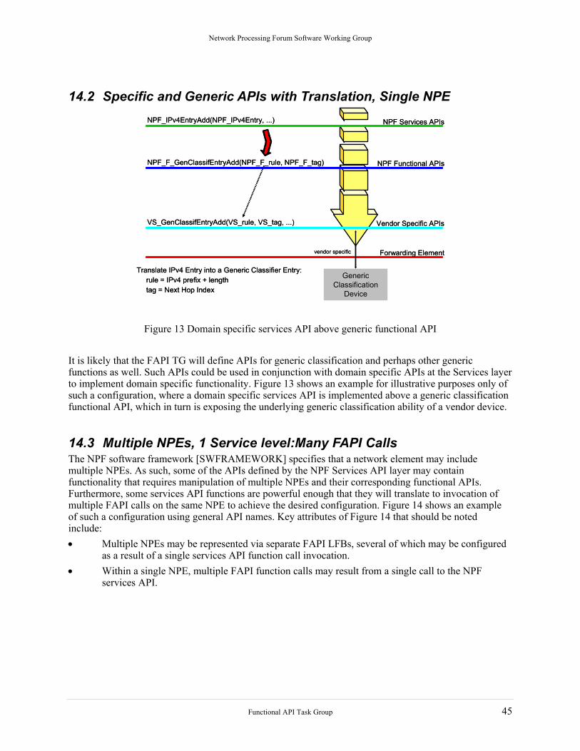
Network Processing Forum Software Working Group
14.2 Specific and Generic APIs with Translation, Single NPE
NPF Services APIs
NPF Functional APIs
Vendor Specific APIs
Forwarding Element
VS_GenClassifEntryAdd(VS_rule, VS_tag, ...)
NPF_F_GenClassifEntryAdd(NPF_F_rule, NPF_F_tag)
NPF_IPv4EntryAdd(NPF_IPv4Entry, ...)
Generic Classification
Device
vendor specific
Translate IPv4 Entry into a Generic Classifier Entry:rule = IPv4 prefix + lengthtag = Next Hop Index
Figure 13 Domain specific services API above generic functional API
It is likely that the FAPI TG will define APIs for generic classification and perhaps other generic functions as well. Such APIs could be used in conjunction with domain specific APIs at the Services layer to implement domain specific functionality. Figure 13 shows an example for illustrative purposes only of such a configuration, where a domain specific services API is implemented above a generic classification functional API, which in turn is exposing the underlying generic classification ability of a vendor device.
14.3 Multiple NPEs, 1 Service level:Many FAPI Calls The NPF software framework [SWFRAMEWORK] specifies that a network element may include multiple NPEs. As such, some of the APIs defined by the NPF Services API layer may contain functionality that requires manipulation of multiple NPEs and their corresponding functional APIs. Furthermore, some services API functions are powerful enough that they will translate to invocation of multiple FAPI calls on the same NPE to achieve the desired configuration. Figure 14 shows an example of such a configuration using general API names. Key attributes of Figure 14 that should be noted include: • Multiple NPEs may be represented via separate FAPI LFBs, several of which may be configured
as a result of a single services API function call invocation. • Within a single NPE, multiple FAPI function calls may result from a single call to the NPF
services API.
Functional API Task Group 45

Network Processing Forum Software Working Group
1 to N mapping of resources in SAPI implementation NPF_xxxAdd(FH77)NPF_F_xxx can be mapped into a Classifier + NPF_F_yyy resources
NPF SAPIsNPF SAPIs
NPF_F_genClassifAdd(GCH)NPF_F_genClassifAdd(GCH)NPF_F_stuffAdd(FH1NPF_F_xxxAdd(FH1)) NPF FAPIsNPF FAPIsNPF_F_otherStuffAddNPF_F_yyyAdd(OSH)(OSH)
VS1_stuffAdd(XXX) VS1_xxxAdd(XXX) VS2_genClassifAdd()VS2_genClassifAdd()
Vendor Specific APIsVS2_otherstuffVS2_yyyAdd() Add()
Vendor Specific APIs
Forwarding ElementForwarding Element
NPE1NPE1 NPE2NPE2 NPE3NPE3
Figure 14 Multiple FAPI Invocations, Multiple NPEs
14.4 Single NPE, Many Service Level:1 FAPI Call Some APIs defined at the services API (and perhaps at the functional API as well) may partition functionality in a manner that is more granular than the functionality provided by a vendor’s implementation. In those cases, multiple separate services or function API calls may be condensed into a single function call in the vendor implementation. Figure 15 provides an example of such a configuration, where multiple NPF function calls may result in addition of a single configuration entry to a NPE. In such a configuration, the software implementation underneath the FAPI must maintain sufficient state as to be able to correlate multiple function calls and make a single function call to the underlying device as a result.
NPF SAPIs NPF SAPIs NPF_F_nnnAdd(FH2)NPF_F_mmmAdd(FH1)
NPF FAPIs NPF FAPIs 2 resources at the FAPI2 resources at the FAPI
synchrosynchro
1 resource in the FE/DD 1 resource in the FE/DD VS1_zzzAdd()Vendor Specific APIsVendor Specific APIs
vendor specificvendor specific Forwarding ElementForwarding Element
FEFE
Figure 15 Multiple NPF Function calls resulting in a single NPE configuration entry
Functional API Task Group 46

Network Processing Forum Software Working Group
APPENDIX A INFORMATIVE ANNEXES
APPENDIX A VARIATIONS ON THE GENERIC FE ARCHITECTURE
FAPI Layer
Meter
IPv4 ForwarderIngress Classifier Egress
Control Plane
Interconnect
Blade 3
Blade 2
Blade 1
Classifier Eth Ingress
Classifier Chip
Phy/ Mac
Blade Functions
IPv4 Forwarder
Meter FramerEgress Data
Plane
DeviceDrivers
NPU OpticalFramer Devices
Blades
Figure 16 Generic Architecture Example
The basic generic NE model is shown in Figure 16. However, this will be implemented in many variations as outlined in the following sections. The list is neither prescriptive nor exhaustive. A common variation will use ForCES protocol for the interconnect as shown in Figure 17.
Device
Figure 17 Basic ForCES CE separation from FE
ForCES ProtocolControl Plane
FAPI Layer
MeterClassifi
erIPv4
ForwarIngress Egress
Data Plane
Blade 3
Blade 2
Eth Ingress
Blade 1
Blades
FAPI Layer
MeterClassifier
IPv4 Forwar
FramerEgress
Blade Functions
Drivers
Phy/ Mac
Classifier Chip
OpticalFramer
NPU
Devices
Functional API Task Group 47

Network Processing Forum Software Working Group
Figure 18 shows various possible interactions between the NPF model and the IETF ForCES protocol. The assumption is that NPF FAPI and the ForCES protocol are semantically identical, that is: • Same LFB model and class definitions. • Same operations. Note: FCL stands for Forwarding Control Layer.
Figure 18 NPF and ForCES Interactions
• Figure 18A shows 2 versions of FCL that can be available from providers. The first, ForCES-FCL,
translates SAPI calls to ForCES protocol messages with no specified NPF FAPI Layer. The second, FAPI-FCL, translates SAPI calls to FAPI calls (current NPF model).
• Figure 18B shows how a ForCES module can be added to a FAPI-FCL module in order to configure ForCES-FEs that may be plugged in the same system containing FAPI-FEs (note that by definition FAPI-FEs do not interpret ForCES messages).
• In the following, it is assumed that the forwarded configuration messages, (ForCES or FAPI) destined to the FE, are interpreted by the FE (e.g. FAPI Implementation is on the FE).
• Figure 18C shows ForCES-FCL communicating through ForCES protocol messages to a ForCES-FE. No NPF FAPIs are involved in this case.
• Figure 18D shows ForCES-FCL communicating through ForCES protocol messages to a FAPI-FE. This FE has a FAPI server configuring its LFBs, thus requiring a translation layer to translate ForCES messages to FAPI calls. This model may be used by integrators that decided to use a FAPI Server in their FEs and implement ForCES as their Messaging Layer.
Functional API Task Group 48

Network Processing Forum Software Working Group
• Figure 18E shows FAPI-FCL communicating through ForCES protocol messages to a ForCES-FE. This model requires a translation layer in the FCL module in order to translate FAPI calls to ForCES protocol messages. This model may be used by integrators that have a FAPI-FCL and purchased a ForCES-FE.
• Figure 18F shows FAPI-FCL communicating through ForCES protocol messages to a FAPI-FE. This model requires a ForCES layer in both the FE and the FCL module. This model may be used by integrators that need a standard/ForCES like protocol for their Inter-process/Messaging communication.
• Figure 18G is the current NPF model with a FAPI-FCL and a FAPI-FE. A proprietary Messaging Layer forwards FAPI function calls between FCL and FEs.
Functional API Task Group 49

Network Processing Forum Software Working Group
APPENDIX B EXAMPLE USAGE OF THE FAPI MODEL & FUNCTION BLOCKS This section combines the APIs and functional blocks described in the previous section to provide examples of how FAPI is expected to be used. Each example provides the sequence of FAPI steps expected to occur in the given scenario. This section should be considered informative only. For the purposes of this example it is not necessary to specify whether the NPF Services APIs are used or not.
APPENDIX C SIMPLE IPV4 ROUTER EXAMPLE
This example assumes a relatively simple system wherein a single blade with Ipv4 forwarding functionality is being controlled and configured via FAPI executing on a control blade. Initially the system is in the “off” state. 1. The first step is to turn the system power on. Interconnects are initialized, memory is allocated,
appropriate drivers and OS code is loaded, etc. All such activity is beyond the scope of NPF. 2. Next, the IPv4 forwarding blade somehow contacts the CP executing in the CP in the control blade.
This might be through proprietary mechanisms, NPF standardized messaging, or via the ForCES protocol [FORCESCH].
3. The CP loads any necessary software for normal operation. This might include implementations of the NPF Services APIs, such as PacketHandler (to support ARP, OSPF and/or BGP protocol) together with applications appropriate to Ipv4 routers (ARP, OSPF, BGP and an SNMP agent for example).
4. The NPF Functional APIs are loaded into memory (perhaps in the form of a statically linked library or a dynamically linked library).
5. The CP software uses the topology discovery APIs to get identifiers for the functional blocks implemented in the forwarding element. Using these APIs the CP retrieves identifiers to two instances of the Ethernet ingress port functional block, one instance of an IPv4 RFC1812 compliant functional block, one instance of a packet handler block, one instance of an Ethernet encapsulation functional block, and two instances of the Ethernet egress port functional block.
6. The CP uses the identifiers it acquired in the previous step to configure the various functional blocks. This might include setting MAC addresses and port speeds, adding LPM-->FlowID entries, and adding FlowID-->DMAC entries to the various functional blocks. The source of this information is outside the scope of NPF specifications.
7. Packets flow through the FE and are processed according to the configuration set up in step 6. The CP will accumulate statistics by requesting counter information using the Interface API, which in turn may be requested from the SNMP agent. The CP may choose to change that configuration on the fly by loading new table entries, deleting entries, etc. Certain packets will be addressed to the system itself: e.g. unicast SNMP requests, ARP responses; multicast messages for OSPF or BGP; or broadcast ARP requests. Some packets may originate from applications in the CP, e.g. requests by, or responses to, the applications just mentioned. These packets will be communicated between CP and FE, e.g. via calls to the PacketHandler.
8. Eventually the system shuts down. Startup and shutdown are beyond the scope of the NPF. The CP software may choose to administratively shut down the Ethernet ports before shutdown via the FAPIs, but that is an implementation decision.
APPENDIX D FIREWALL EXAMPLE
This example assumes a simple system configuration, again with a single blade performing control functions and a single blade performing basic firewall functionality. For the purposes of this example the overall system will function as a basic stateful firewall operating in “bump in the wire” mode.
Functional API Task Group 50

Network Processing Forum Software Working Group
1. The first step is to turn the system power on. Interconnects are initialized, memory is allocated, appropriate drivers and OS code is loaded, etc. All such activity is beyond the scope of NPF.
2. Next, the firewall blade somehow contacts the CP executing in the CE on the control blade. This might be through proprietary mechanisms, NPF standardized messaging, or via the ForCES protocol.
3. The CP loads any necessary software for normal operation. This might include implementations of the NPF Services APIs and policy applications to provide data to configure the firewall functions. For the purposes of this example it is not necessarily to specify whether the NPF Services APIs are used or not.
4. The NPF Functional APIs are loaded into memory (perhaps in the form of a statically linked library or a dynamically linked library).
5. The CP software uses the topology discovery APIs to get handles to the functional blocks implemented in the forwarding blade. Using these APIs the control blade retrieves handles to one instance of an Ethernet ingress port functional block, one instance of a classifier functional block, one instance of a dropper block, one instance of a packet handler functional block, and one instance of an Ethernet egress port functional block.
6. The CP uses the handles it acquired in the previous step to configure the various functional blocks. This might include setting MAC addresses and port speeds, adding a default rule to the classifier that forwards all otherwise unmatched packets to the dropper block, and adding rule entries for passing TCP and UDP packets to the packet handler block.
7. Packets flow through the FE and are processed according to the configuration in step 6. The CP examines received UDP and TCP packets, communicated by the packet handler block, and dynamically installs rules to allow permitted flows to pass while causing other flows to be dropped.
8. Eventually the system shuts down. Startup and shutdown are beyond the scope of the NPF. The CP software may choose to administratively shut down the Ethernet ports before shutdown via the FAPIs, but that is an implementation decision.
Functional API Task Group 51

Network Processing Forum Software Working Group
APPENDIX B ACKNOWLEDGEMENTS
Working Group Chair: Alex Conta, Transwitch, [email protected]
Task Group Chair: Alistair Munro, U4EA Technologies, [email protected] The following individuals are acknowledged for their participation to the Functional API Task Group teleconferences, plenary meetings, mailing list, and/or for their NPF contributions used for the development of this Implementation Agreement. This list may not be all-inclusive since only names supplied by member companies for inclusion here will be listed. The NPF wishes to thank all active participants to this Implementation Agreement, whether listed here or not. The list is in alphabetical order of last names:
Name Company Gamil Cain Intel Corp. Philippe Damon IBM Jason Goldschmidt Sun Reda Haddad Ericsson Zsolt Harazsti Modular Networks, Inc. Hormuzd Khosravi Intel Corp. Vinoj Kumar Agere Systems David Maxwell IDT Alistair Munro (ed.) U4EA Technologies Ltd. Steve Nadas Ericsson David Putzolu (ed.) Intel Corp. John Renwick Agere
Functional API Task Group 52
Network Processing Forum Software Working Group
Functional API Task Group 53
APPENDIX C LIST OF COMPANIES BELONGING TO NPF DURING APPROVAL PROCESS
Agere Systems FutureSoft Nokia
Altera HCL Technologies Nortel Networks
AMCC Hifn NTT Electronics
Analog Devices IBM PMC Sierra
Avici Systems IDT Seaway Networks
Cypress Semiconductor Intel Sensory Networks
Enigma Semiconductor IP Fabrics Sun Microsystems
Ericsson IP Infusion Teja Technologies
Erlang Technologies Kawasaki LSI TranSwitch
ETRI Modular Networks U4EA Group
EZChip Motorola Xelerated
Flextronics NetLogic Xilinx