function point analysis: a quick and easy primer · itmpi005 click to edit master title 1. david...
TRANSCRIPT

T11 Concurrent Session Thursday 06/12/2008 1:00 PM – 2:30 PM
Function Point Analysis: A Quick and Easy Primer
Presented by:
David Garmus & David Herron The David Consulting Group
Presented at: Better Software Conference & EXPO
June 9 – 12 2008: Las Vegas, NV, USA
330 Corporate Way, Suite 300, Orange Park, FL 32043 888-268-8770 904-278-0524 [email protected] www.sqe.com

David Garmus David Garmus is a founder of The David Consulting Group (an SEI CMMI® Approved Transition Partner) and supports software development organizations in achieving software excellence with a metric-centered approach. David is an acknowledged authority in the sizing, measurement, and estimation of software application development. He is a past president of the International Function Point Users Group (IFPUG) and a member of their Counting Practices Committee. David has spoken at numerous conferences and written many articles and several books.
David Herron David Herron is an acknowledged authority in the use of metrics to monitor the impact of Information Technology (IT) on the business and on the advancement of IT organizations to higher levels of software process maturity. He is a noted author and lecturer and has addressed audiences throughout the US and Europe on performance measurement, software process improvement, and outsourcing governance. With David Garmus, David Herron has co-authored two books on functional measurement. David Herron’s current engagements include senior-level consulting and coaching on matters relating to organizational change management, team, and individual mentoring.

ITMPI005
Click To Edit Master Title
1
David Garmus and David Herron
June 2008Better Software Conference
Function Point Analysis: A Quick and Easy Primer

2
Topics of Discussion
Function Point Analysis, Uses and Benefits
• Objectives of Function Point Analysis• Benefits of Function Point Analysis• A High Level View• Function Point Counting Process
Function Point Counting Rules
• Types of Function Point Counts• Steps in Counting• Data Functions• Transactional Functions• General System Characteristics

3
Function Point Analysis is a standardized method for measuring thefunctionality delivered to an end user.
• Consistent method • Easy to learn• Available early in the lifecycle• Acceptable level of accuracy• Meaningful internally and externally
• Objectives• Measure functionality that the user requests and receives• Measure software development and maintenance independently of technology used for implementation
Why Function Point Analysis?

4
• A vehicle to estimate cost and resources required for software development, enhancement and maintenance
• A tool to quantify performance levels and to monitor progress made from software process improvement initiatives
• A tool to determine the benefit of an application to an organization by counting functions that specifically match requirements
• A tool to size or evaluate purchased application packages
Benefits of Using Function Points

5
• Data Functions• Internal Groupings of data called Internal Logical Files (ILF)• External Groupings of data or External Interface Files (EIF)• The term file does not refer to files in the physical sense,
rather refers to logical data stores, entities, objects or super-classes
• Transaction Functions• External Inputs (EI)• External Outputs (EO)• External Inquires (EQ)
• General System Characteristics
We will explore the definitions of each of thesecomponents in the next module
Overview
FP Evaluates These Components
External Input
External Inquiry External
Output
InternalLogical
Files
External Interface
File
Application

6
Function Point Process
1. Determine the type of Function Point count
2. Identify the counting scope and application boundary
3. Count the data functions to determine their contribution to the unadjusted function point count
4. Count the transactional functions to determine their contribution to the unadjusted function point count
5. Determine the value adjustment factor - 14 General System Characteristics
6. Calculate adjusted function point count
Process

7
Types of Function Point Count
• Development Project Function Point Count• Measures the functions provided to users with first install of
the software delivered when project is complete
• Enhancement Project Function Point Count• Measures the modifications to existing application
add, change or delete user functions delivered when project is complete
• When functionality is installed, the application count must be updated to reflect changes in the application functionality
Step 1: Type of Count

8
Types of Function Point Count
• Application Function Point Count
• Measures an installed application • Also referred to as the baseline or installed count• Provides count of the current functions provided to users• Number is initialized when the development project function
point count is completed• It is updated every time completion of an enhancement project
alters the application's functions
Step 1: Type of Count

9
Scope and Boundary
• Definition:• A function point count provides an answer to a business
problem
• Purpose:• Determines the type of function point count and scope of
required count • Influences the positioning of the boundary between the
software under review and the surrounding software
Step 2: Boundary

10
Other Applications
Application Boundary
External Input
External Inquiry
External Output
Other Applications
ExternalInput
External Output
Internal Logical File
External Interface File
Internal Logical File
Diagramming an Application Boundary
Step 2: Boundary

11
• Data functions represent the functionality provided to the user to meet internal and external data requirements
• Internal Logical Files (ILFs) • External Interface Files (EIFs)
• The term file here does not mean file in the traditional data processing sense; in this case, file refers to a logically related group of data and not the physical implementation of those groups of data
Data Functions
Step 3: Data

12
• An internal logical file (ILF) is a user identifiablegroup of logically related data or control information maintained within the boundary of the application
• The primary intent of an ILF is to hold data maintained through one or more elementary processes of the application being counted
Step 3: Data
Internal Logical Files
13
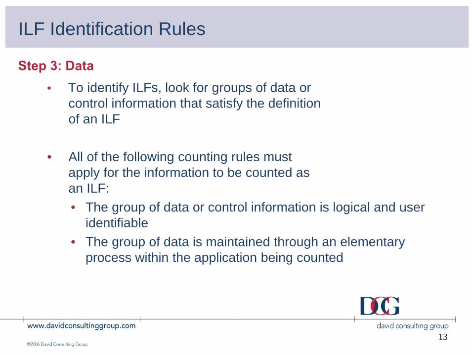
• To identify ILFs, look for groups of data orcontrol information that satisfy the definitionof an ILF
• All of the following counting rules mustapply for the information to be counted asan ILF:• The group of data or control information is logical and user
identifiable• The group of data is maintained through an elementary
process within the application being counted
ILF Identification Rules
Step 3: Data

14
ILF Examples
• Count as Internal Logical Files
• Application transaction data maintained within the application
• ILFs maintained by more than one application
Step 3: Data

15
• An external interface file (EIF) is a user identifiable group of logically related data or control information referenced by the application, but maintained within the boundary of another application
• The primary intent of an EIF is to hold data referenced through one or more elementary processes within the application of the application counted; this means an EIF counted for the application must be an ILF in another application
External Interface Files
Step 3: Data
16
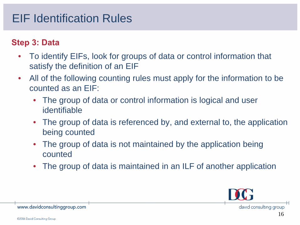
• To identify EIFs, look for groups of data or control information that satisfy the definition of an EIF
• All of the following counting rules must apply for the information to be counted as an EIF:• The group of data or control information is logical and user
identifiable• The group of data is referenced by, and external to, the application
being counted• The group of data is not maintained by the application being
counted • The group of data is maintained in an ILF of another application
Step 3: Data
EIF Identification Rules

17
EIF Examples
• Count as External Interface Files
• Reference data or edit criteria obtained or read from ILFs maintained by other applications
• System information not maintained within counted application, but required to produce outputs/inquiries
Step 3: Data

18
The primary difference between an internal logical file(ILF) and an external interface file (EIF) is that an EIF is not maintained by the application being counted, while an ILF is.
ILF/EIF Difference
Step 3: Data

19
Assign each identified ILF and EIF a functional complexity based on the number of data element types (DETs) and record element types (RETs) associated with the ILF or EIF, within that application
INTERNAL LOGICAL OREXTERNAL INTERFACE FILES:
Record Element Types
Data Elements1-19 20-50 51+
<2 Low2-5 Average High>5
LowLow Average
HighAverage High
(Data SubGroups)
(Sum of all fieldsof all subgroupsof the logical datagrouping)
ILF/EIF Complexity Matrix
Step 3: Data

20
“Instructor Data”Entity Element LengthINSTRUCTOR
Name 30Last NameFirst NameMiddle Init
Address 50City 30State 20Zip 9Telephone 10
COURSES TAUGHTInstructor Name 30
Last NameFirst NameMiddle Init
Course Name 20Course Number 8
CoursesTaught
Dependenton
Instructor
Internal Logical File Example
Step 3: Data

21
Solution
Sample Counting Form
Step 3: Data
DescriptionILF/EIF
EI/EO/ EQRET/ DET
FTR Complexity
INSTRUCTOR DATA ILF 2 8 Low

22
The Customer Address File is used to print the addresses on the bills. No Billing System files are updated with this data.
Completed Orders File updates the Billing Master and cause the bills to be processed.
CustomerAddress File
CompletedOrders File
BILLING SYSTEM
Billing Master
External Interface File Example
Step 3: Data

23
Solution
Step 3: Data
DescriptionILF/EIF
EI/EO/ EQRET/ FTR
DET Complexity
CUSTOMER ADDRESS FILEBILLING MASTER FILECOMPLETED ORDERS FILE
EIFILF─

24
Transaction Functions
• Transactional functions represent the functionality provided to the user for the processing of data by an application
• Transactional functions are defined by their elementary process and primary intent as follows:• For the Elementary Processes where the Primary Intent is to
maintain an ILF or to alter the behavior of the system:• External Inputs (EIs)
• For the Elementary Processes where the Primary Intent is to present information to the user and that perform calculations, derive data, update an ILF or alter the behavior of the system:
• External Outputs (EOs)• For the Elementary Processes where the Primary Intent is to present
information to the user and that do not perform calculations, derive data, update an ILF or alter the behavior of the system
• External Inquiries (EQs)
Step 4: Transactions

25
Legend:PI: primary intent of the transaction functionF: function of the transaction function, but is not the primary intent
and is sometimes presentN/A: the function is not allowed by the transaction function
Summary of Functions (EI, EO, EQ)
Step 4: Transactions
Function EI EO EQAlter the behavior of the system PI F N/A
Maintain one or more ILF PI F N/A
Present information to the user F PI PI

26
Summary Of Processing Logic (EI, EO, EQ)
Step 4: TransactionsPROCESSING LOGIC EI EO EQ
Validations are performed C C C
Mathematical formulae or calculations are performed C M* N
Equivalent values are converted C C C
Data is filtered and selected using specified criteria to compare multiple sets of data C C C
Conditions are analyzed to determine which are applicable C C C
At least one ILF is updated M* M* N
At least one ILF or EIF is referenced C C M
Data or control information is retrieved C C M
Derived data is created C M* N
Behavior of the system is altered M* M* N
Prepare and present information outside the boundary C M M
Capability to accept data or control information that enters the application boundary M C C
Resorting or rearranging of data C C C
27
External Inputs
• An external input is an elementary process that processes data or control information that comes from outside the application’s boundary
• The primary intent of an EI is to maintain one or more ILFs and/or to alter the behavior of the system
Step 4: External Input

28
EI Identification Rules
All of the following counting rules must apply for data being processed to be counted as an external input:
• The data or control information is received from outside the application boundary
• At least one ILF is maintained if the data entering the boundary is not control information that alters the behavior of the system
• For the identified process, one of the three statements must apply:
• Processing logic is unique from processing logic performed by other EIs for the application
• The set of data elements identified are different from the sets identified for other EIs in the application
• The ILFs or EIFs referenced are different from the files referenced by the other EIs in the application
Step 4: External Input

29
EI Examples
Count as External Input• Transactional data• Screen or batch input• Messages from other applications• Control Information• User functions• Physical data which initiates processing
Don’t count as External Input• Reference data (EIFs)• Input side of EQ or EO• Menu screens• Logon screens• Multiple methods of invoking similar logic• Navigation
Step 4: External Input

30
Complexity for External Inputs is based on the number of logical groups (FTRs) and fields (DETs) for the EI
Guideline: When estimating a FP count, use average unless High is obvious
<2 2
>2
Low
Average HighLow
Low Average
HighAverage High
EXTERNAL INPUT:
File Types Data ElementsReferenced 1-4 5-15 16+
(Data Groups)(Fields)
EI Complexity Matrix
Step 4: External Input

31
Course Registration Screen
NAME ____________________ START DATE (PK)______
SSN (PK)_____________________
COURSE # (PK)________________
COURSE TITLE ____________
LOCATION ________________ ACTION (A, C OR D)____
(Both Error and Confirmation Messages Occur)
STUDENT and COURSE are updated/referenced.
Step 4: External Input
External Input Example

32
Solution
Step 4: External Input
DescriptionILF/EIF EI/EO/
EQ
RET/ FTR
DET Complexity
REGISTRATION FORM (Add)REGISTRATION FORM (Change) REGISTRATION FORM (Delete)
EIEIEI
222
885
AvgAvgAvg

33
• An external output (EO) is an elementary process that sends data or control information outside the application’s boundary
• The primary intent of an external output is to present information to a user through the processing logic other than or in addition to the retrieval of data or control information
• The processing logic must contain at least one mathematical formula or calculation, create derived data, maintain one or more ILFs and/or alter the behavior of the system
Step 4: External Outputs
External Outputs

34
All of the following counting rules must apply for the elementary process to be counted as an external output:
• Sends data or control information external to the application’s boundary
• For the identified process, one of the three statements must apply:
• Processing logic is unique from the processing logic performed by other EOs for the application
• The set of data elements identified are different from other EOs in the application
• The ILFs or EIFs referenced are different from files referenced by other EOs in the application
EO Identification Rules
Step 4: External Outputs

35
In addition, one of the following rules must apply:
• The processing logic contains at least one mathematical formula or calculation
• Derived data is created• The processing logic maintains at least one ILF• The processing logic alters the behavior of the system
Step 4: External Outputs
EO Identification Rules

36
External Output Examples
Count as External Output• Data transfers to other applications with calculations• Reports with calculations• On-line reports with calculated information• Derived data displayed on a screen• Message/file sent to another system, that includes an update (send a check
for payment, and update an ILF that the check has been processed)• Note: Summary fields on a report are not counted as a separate EO; these
computed fields are DETs within the same EO
Don’t count as External Output• Reports without other processing (calculations, update, etc.)• Identical reports/unique data values• Resorting or rearrangement of a set of data without other processing logic
Step 4: External Outputs

37
Complexity is based on the number of FTRs/DETs for the EO
File Types Data ElementsReferenced 1-5 6-19 20+
<2 2 or 3
>3
Low
Average HighLow
Low Average
HighAverage High
EXTERNAL OUTPUT:
(Data Groups)(Fields)
EO Complexity Matrix
Step 4: External Outputs
38
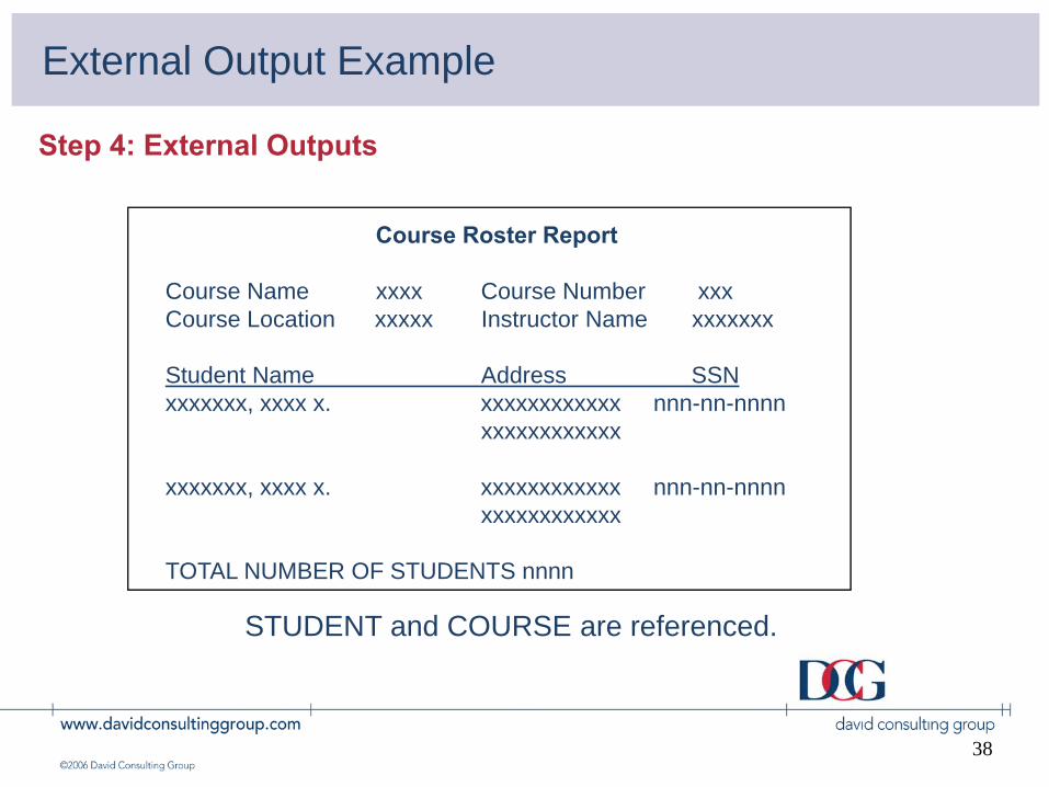
Course Roster Report
Course Name xxxx Course Number xxxCourse Location xxxxx Instructor Name xxxxxxx
Student Name Address SSNxxxxxxx, xxxx x. xxxxxxxxxxxx nnn-nn-nnnn
xxxxxxxxxxxx
xxxxxxx, xxxx x. xxxxxxxxxxxx nnn-nn-nnnnxxxxxxxxxxxx
TOTAL NUMBER OF STUDENTS nnnn
STUDENT and COURSE are referenced.
Step 4: External Outputs
External Output Example

39
Solution
Step 4: External Outputs
DescriptionILF/EIF
EI/EO/ EQRET/ FTR DET Complexity
COURSE ROSTER EO 2 8 Avg

40
• An external inquiry (EQ) is an elementary process that sends data or control information outside the application boundary
• The primary intent of an external inquiry is to present information to the user through the retrieval of data or control information
• The processing logic contains no mathematical formula or calculation, and creates no derived data
• No ILF is maintained during the processing, nor is the behavior of the system altered
Step 4: External Inquiries
External Inquiries
41
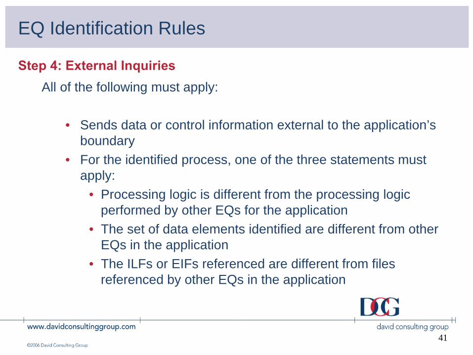
All of the following must apply:
• Sends data or control information external to the application’s boundary
• For the identified process, one of the three statements must apply:
• Processing logic is different from the processing logic performed by other EQs for the application
• The set of data elements identified are different from other EQs in the application
• The ILFs or EIFs referenced are different from files referenced by other EQs in the application
Step 4: External Inquiries
EQ Identification Rules

42
• In addition, all of the following rules must apply:
• The processing logic retrieves data or control information from one or more ILFs or EIFs
• The processing logic does not contain mathematical formula or calculation
• The processing logic does not create derived data• The processing logic does not alter the behavior of the system• The processing logic does not maintain an ILF
Step 4: External Inquiries
EQ Identification Rules

43
External Inquiry Examples
• Count as an External Inquiry• User functions such as view, lookup, display, browse, drop down• Logon screens that provide application specific security• Help - each level• Output that contains no calculated, derived data
• Don’t count as External Inquiry• Multiple methods of invoking the same inquiry logic• Inquiries that can be accessed from multiple areas/screens of an application
(count once)• Logon screens that do not provide security• Derived data vs. retrieval of data• Resorting or rearrangement of the same set of data without other processing
logic
Step 4: External Inquiries

44
Complexity is based on the number of FTRs/DETs for the EQ
EXTERNAL INQUIRY:
File Types Data ElementsReferenced 1-5 6-19 20+
1 2 or 3
>3
Low
Average HighLow
Low Average
HighAverage High
(Fields)(Data Groups)
EQ Complexity Matrix
Step 4: External Inquiries

45
Restaurant Selection
S TypeItalian
x MexicanBistro
Restaurant Selection
Name: TACO BELLLocation: EVERY CORNERGolden Spoon Rating -2Price Range CHEAPReservations Never Needed
Screen1 - input Screen 2 - output
Step 4: External Inquiries
External Inquiry Examples

46
College Credits Report
Student Course Number Course Date Creditsxxxxxxxxxxx, xxx nnnnnnn nn/nn/nnnn nnnnxxxxxxxxxxx, xxx nnnnnnn nn/nn/nnnn nnnnxxxxxxxxxxx, xxx nnnnnnn nn/nn/nnnn nnnnxxxxxxxxxxx, xxx nnnnnnn nn/nn/nnnn nnnnxxxxxxxxxxx, xxx nnnnnnn nn/nn/nnnn nnnn
Step 4: External Inquiries
External Inquiry Examples
(Info is retrieved from Course ILF)

47
Solution
Step 4: External Inquiries
DescriptionILF/EIF EI/EO/
EQ
RET/ FTR
DET Complexity
RESTAURANT SELECTIONCOLLEGE CREDITS REPORT
EQEQ
11
74
LowLow

48
Functionality requested by the user may be organized intological parts that match the five function point components
External Interface File
USERADD, CHGINVOICES PAYMENTS
VENDOR
INVOICES
ACCOUNTS PAYABLE
USER
PAYMENTS
USER
PAYMENTSTATUS
USER
PAIDINVOICES
PURCHASEORDER INFO
PURCHASEORDERSYSTEMExternal Inputs
External Input
External Inquiry
External Output
Internal Logical Files
Managing Requirements

49
Data Communication On-Line Update
Distributed Data or Processing Complex Processing
Performance Objectives Reusability
Heavily Used Configuration Conversion & Install Ease
Transaction Rate Operational Ease
On-Line Data Entry Multiple-Site Use
End-User Efficiency Facilitate Change
General System Characteristics
Step 5: Determine VAF

50
• The value adjustment factor looks at 14 general system characteristics.
• Each characteristic is given a value
• Once all 14 GSCs have been evaluated, the VAF is computed:
Σ(DI) = TDI(TDI * .01) + .65 = VAF
Value Adjustment Factor (VAF)
Step 5: Determine VAF
51
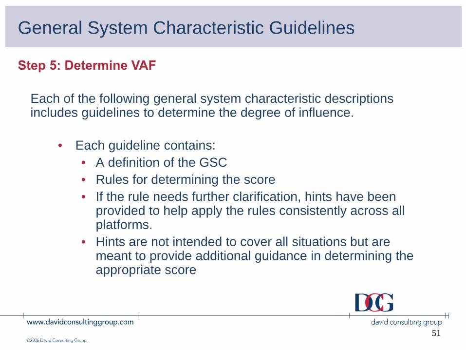
General System Characteristic Guidelines
• Each guideline contains:• A definition of the GSC• Rules for determining the score• If the rule needs further clarification, hints have been
provided to help apply the rules consistently across all platforms.
• Hints are not intended to cover all situations but are meant to provide additional guidance in determining the appropriate score
Step 5: Determine VAF
Each of the following general system characteristic descriptions includes guidelines to determine the degree of influence.

52
Formulas
• Total Degree of Influence (TDI) = Sum of DIs from all 14 GSCs
• Value Adjustment Factor (VAF) = (.65 + (.01 x TDI))
• Adjusted Function Points = Unadjusted FP x VAF
• NOTE: There are different algorithms for:• Development• Enhancement• Original Application • Revised Application Counts
Step 6: Final Calculation

53
• A vehicle to estimate cost and resources required for software development, enhancement and maintenance
• A tool to quantify performance levels and to monitor progress made from software process improvement initiatives
• A tool to determine the benefit of an application to an organization by counting functions that specifically match requirements
• A tool to size or evaluate purchased application packages
Just to Summarize…

54
References
For more information:
• The David Consulting Group• www.davidconsultinggroup.com
• International Software Benchmarking Standards Group• www.isbsg.org.au
• International Function Point Users Group• www.ifpug.org
• Software Engineering Institute, Project Sizing & Estimating• www.cmu.sei.edu