fuller mid-range transmissions trsm0160 - eatonpub/@eaton/@roadranger/...(61 6) 342-3344 every...
TRANSCRIPT

Service Manual
Fuller Mid-Range TransmissionsTRSM0160October 2007
FS-5106AFS-6206A
Before starting a vehicle always beseated in the drivers seat, place thetransmission in neutral, set the park-ing brakes and disengage the clutch.
Before working on a vehicle place thetransmission in neutral, set the park-ing brakes and block the wheels.
Before towing the vehicle place thetransmission in neutral, and lift therear wheels off the ground or discon-nect the driveline to avoid damage tothe transmission during towing.c U T 8 0 0 7 k 1 / 8 8
©1989 Eaton Corporation. All rights reserved.
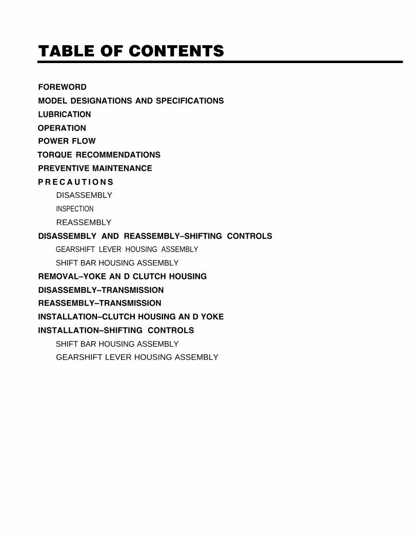
TABLE OF CONTENTS
FOREWORD
MODEL DESIGNATIONS AND SPECIFICATIONS
LUBRICATION
OPERATION
POWER FLOW
TORQUE RECOMMENDATIONS
PREVENTIVE MAINTENANCE
P R E C A U T I O N S
DISASSEMBLY
INSPECTION
REASSEMBLY
DISASSEMBLY AND REASSEMBLY–SHIFTING CONTROLS
GEARSHIFT LEVER HOUSING ASSEMBLY
SHIFT BAR HOUSING ASSEMBLY
REMOVAL–YOKE AN D CLUTCH HOUSING
DISASSEMBLY–TRANSMISSION
REASSEMBLY–TRANSMISSION
INSTALLATION–CLUTCH HOUSING AN D YOKE
INSTALLATION–SHIFTING CONTROLS
SHIFT BAR HOUSING ASSEMBLY
GEARSHIFT LEVER HOUSING ASSEMBLY
FOREWORDThis manual is designed to provide detailed informa-tion necessary to service and repair the Fuller@Transmission listed on the cover.
As outlined in the Table of Contents, the manual isdivided into 3 main sections:
a. Technical information and referenceb. Removal, disassembly, reassembly and
installationc. Options
The format of the manual is designed to befollowed in its entirety if complete disassembly andreassembly of the transmission is necessary. But ifonly one component of the transmission needs to berepaired, refer to the Table of Contents for the pagenumbers showing that component. For example, ifyou need to work on the Shift Bar Housing, you willfind instructions for removal, disassembly and reas-sembly on page 18. Instructions for installation areon page 53. Service Manuals, Illustrated Parts Lists,Drivers Instructions, and other forms of product
service information for these and other Fuller Trans-missions are available upon request. A TechnicalLiterature Order Form may be found in the back ofthis manual. You may also obtain Service Bulletins,detailing information on product improvements, re-pair procedures and other service-related subjectsby writing to the following address:
EATON CORPORATIONTRANSMISSION DIVISIONTechnical Service DepartmentPO. Box 4013Kalamazoo, Michigan 49003(61 6) 342-3344
Every effort has been made to ensure the accuracy of all information in this brochure. However, Eaton Transmission Division makes no expressed orimplied warranty or representation based on the enclosed information. Any errors or omissions may be reported to Training and Publications, EatonTransmission Division, PO, Box 4013, Kalamazoo, Ml 49003,
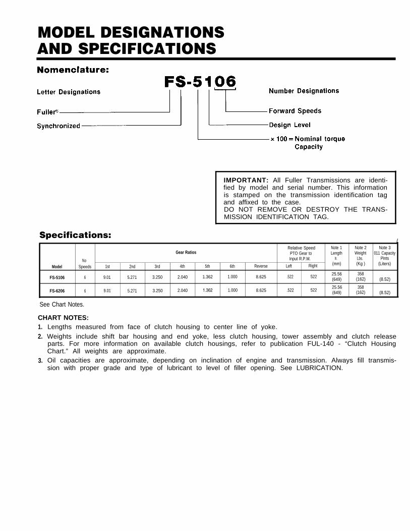
MODEL DESIGNATIONSAND SPECIFICATIONS
IMPORTANT: All Fuller Transmissions are identi-fied by model and serial number. This informationis stamped on the transmission identification tagand affixed to the case.DO NOT REMOVE OR DESTROY THE TRANS-MISSION IDENTIFICATION TAG.
Specifications:/
Relative Speed Note 1Gear Ratios
Note 2 Note 3PTO Gear to Length Weight 011 Capacity
No Input R.P.M. In. Lbs. Pints
Model Speeds 1st 2nd 3rd 4th 5th 6th Reverse Left Right (mm) (Kg ) (Liters)
FS-5106 6 9.01 5.271 3.250 2.040 1.362 1.000 8.625 .522 522 25.56 358(649) (162) (8.52)
FS-6206 6 9.01 5.271 3.250 2.040 1.362 1.000 8.625 .522 52225.56 358(649) (162) (8.52)
See Chart Notes.
CHART NOTES:1.2.
3.
Lengths measured from face of clutch housing to center line of yoke.Weights include shift bar housing and end yoke, less clutch housing, tower assembly and clutch releaseparts. For more information on available clutch housings, refer to publication FUL-140 - “Clutch HousingChart.” All weights are approximate.Oil capacities are approximate, depending on inclination of engine and transmission. Always fill transmis-sion with proper grade and type of lubricant to level of filler opening. See LUBRICATION.
LUBRICATION
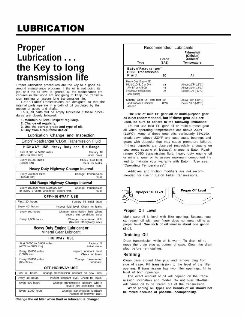
ProperLubrication . . .the Key to longtransmission lifeProper lubrication procedures are the key to a good all-around maintenance program. If the oil is not doing itsjob, or if the oil level is ignored, all the maintenance pro-cedures in the world are not going to keep the transmis-sion running or assure long transmission life.
Eaton® Fuller® Transmissions are designed so that theinternal parts operate in a bath of oil circulated by themotion of gears and shafts.
Thus, all parts will be amply lubricated if these proce-dures are closely followed:
1. Maintain oil level. Inspect regularly.2. Change oil regularly.3. Use the correct grade and type of oil.4. Buy from a reputable dealer.
Lubrication Change and Inspection
I Eaton® Roadranger® CD50 Transmission FluidHIGHWAY USE—Heavy Duty and Mid-Range
First 3,000 to 5,000 miles Factory fill(4827 to 8045 Km) Initial drain,
I Every 10,000 miles Check fluid level.(16090 Km) Check for leaks. I
Heavy Duty Highway Change IntervalEvery 250,000 miles Change transmission(402336 Km) fluid.
Mid-Range Highway Change IntervalEvery 100,000 miles (160,000 Km) Change transmissionor every 3 years whichever occurs first. fluld.
I OFF-HIGHWAY USE First 30 hours Factory fill initial drain, I
Every 40 hours Inspect fluid level. Check for leaks. I
Every 500 hours Change transmission fluld wheresevere dirt conditions exist.
Every 1,000 hours Change transmission fluld(Normal off-highway use).
Heavy Duty Engine Lubricant orMineral Gear Lubricant
HIGHWAY USEFirst 3,000 to 5,000 miles Factory fill(4827 to 8045 Km) initial drain.
I Every 10,000 miles Inspect lubricant level.(16090 Km) Check for leaks. IEvery 50,000 miles Change transmission(80450 Km) lubricant.
OFF-HIGHWAY USE First 30 hours Change transmission lubricant on new units. I
Every 40 hours Inspect lubricant level. Check for leaks. IEvery 500 hours Change transmission lubricant where
severe dirt conditions exist.
Every 1,000 hours Change transmission lubricant(Normal off-highway use).
Recommended LubricantsFahrenheit(Celsius)
Grade AmbientType (SAE) Temperature
Ea ton® Roadranger®
CD50 TransmissionF l u i d 50 All
Heavy Duty Engine 011MIL-L-2104B, C or D or 50 Above 10°F(-12°C.)API-SF or API-CD 4 0 Above 10°F(-12°C.)
(Previous API deslgnations 30 Below 10°F(-12°C)acceptable)
Mineral Gear Oil with rust 90 Above 10°F(-12°C)and oxidation Inhibitor 80W Below 10 °F(-12°C)API-GL-1
The use of mild EP gear oil or multi-purpose gearoil is not recommended, but if these gear oils areused, be sure to adhere to the following limitations:
Do not use mild EP gear oil or multi-purpose gearoil when operating temperatures are above 230°F(110°C). Many of these gear oils, particularly 85W140,break down above 230°F and coat seals, bearings andgears with deposits that may cause premature failures.If these deposits are observed (especially a coating onseal areas causing oil leakage), change to Eaton Road-ranger CD50 transmission fluid, heavy duty engine oilor mineral gear oil to assure maximum component lifeand to maintain your warranty with Eaton. (Also see“Operating Temperatures”.)
Additives and friction modifiers are not recom-mended for use in Eaton Fuller transmissions.
Proper Oil LevelMake sure oil is level with filler opening. Because youcan reach oil with your finger does not mean oil is atproper level. One inch of oil level is about one gallonof oil.
Draining OilDrain transmission while oil is warm. To drain oil re-move the drain plug at bottom of case. Clean the drainplug before re-installing.
RefillingClean case around filler plug and remove plug fromside of case. Fill transmission to the level of the filleropening. If transmission has two filler openings, fill tolevel of both openings.
The exact amount of oil will depend on the trans-mission inclination and model. Do not over fill—thiswill cause oil to be forced out of the transmission.
When adding oil, types and brands of oil should notbe mixed because of possible incompatibility.
Change the oil filter when fluid or lubricant is changed.

LUBRICATION
Operating Temperatures—With Eaton® Roadranger®
CD50 Transmission FluidHeavy Duty Engine Oiland Mineral Oil
The transmission should not be operated con-sistently at temperatures above 250°F (120°C).However, intermittent operating temperaturesto 300°F (149°C) will not harm the transmis-sion. Operating temperatures above 250°Fincrease the lubricant’s rate of oxidation andshorten its effective life. When the averageoperating temperature is above 250°F, thetransmission may require more frequent oilchanges or external cooling.
The following conditions in any combina-tion can cause operating temperatures of over250°F: (1) operating consistently at slowspeeds, (2) high ambient temperatures, (3) re-stricted air flow around transmission, (4) ex-haust system too close to transmission, (5)high horsepower, overdrive operation.
External oil coolers are available to reduceoperating temperatures when the above condi-tions are encountered.
Transmission Oil Coolers are:
Recommended— With engines of 350 H.P. and above
with overdrive transmissions
Required— With engines 399 H.P. and above with
overdrive transmissions and GCW’Sover 90,000 lbs.
— With engines 399 H.P. and above and1400 Lbs.-Ft. or greater torque
— With engines 450 H.P. and above
— With EP or Multipurpose Gear OilMild EP gear oil and multipurpose gear oil arenot recommended when lubricant operatingtemperatures are above 230°F (110°C). In addi-tion, transmission oil coolers are not recom-mended with these gear oils since the oilcooler materials may be attacked by thesegear oils. The lower temperature limit and oilcooler restriction with these gear oils gener-ally limit their success to milder applications.
Proper Lubrication Levelsas Related to TransmissionInstallation AnglesIf the transmission operating angle is morethan 12 degrees, improper lubrication can oc-cur. The operating angle is the transmissionmounting angle in the chassis plus the per-cent of upgrade (expressed in degrees).
The chart below illustrates the safe percentof upgrade on which the transmission can beused with various chassis mounting angles.For example: if you have a 4 degree transmis-sion mounting angle, then 8 degrees (or 14percent of grade) is equal to the limit of 12degrees. If you have a O degree mountingangle, the transmission can be operated on a12 degree (21 percent) grade.
Anytime the transmission operating angle of12 degrees is exceeded for an extendedperiod of time the transmission should beequipped with an oil pump or cooler kit toinsure proper lubrication.
Note on the chart the effect low oil levelscan have on safe operating angles. Allowingthe oil level to fall 1/2" below the filler plughole reduces the degree of grade by approxi-mately 3 degrees (5.5 percent).
Proper Lubrication Levels are Essential!
Transmission Mounting AngleDotted line showing “2 Quarts Low” is forreference only. Not recommended.
5
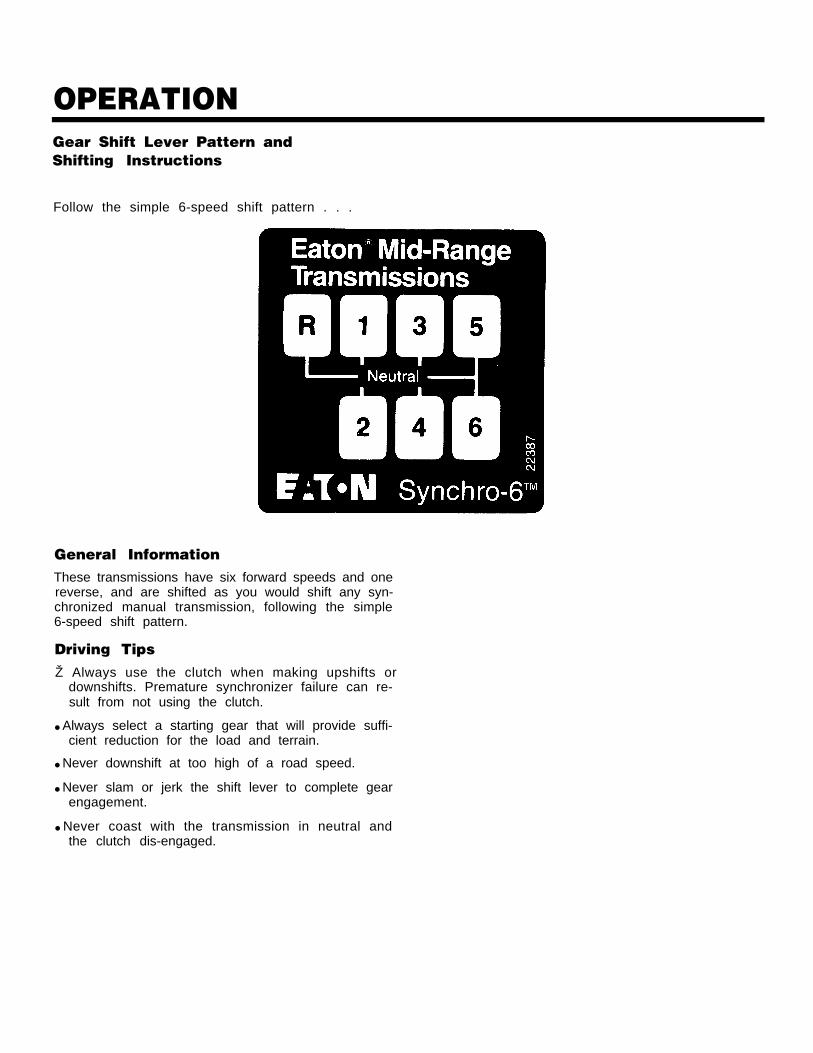
OPERATIONGear Shift Lever Pattern andShifting Instructions
Follow the simple 6-speed shift pattern . . .
General InformationThese transmissions have six forward speeds and onereverse, and are shifted as you would shift any syn-chronized manual transmission, following the simple6-speed shift pattern.
Driving TipsŽ Always use the clutch when making upshifts or
downshifts. Premature synchronizer failure can re-sult from not using the clutch.
● Always select a starting gear that will provide suffi-cient reduction for the load and terrain.
● Never downshift at too high of a road speed.
● Never slam or jerk the shift lever to complete gearengagement.
● Never coast with the transmission in neutral andthe clutch dis-engaged.
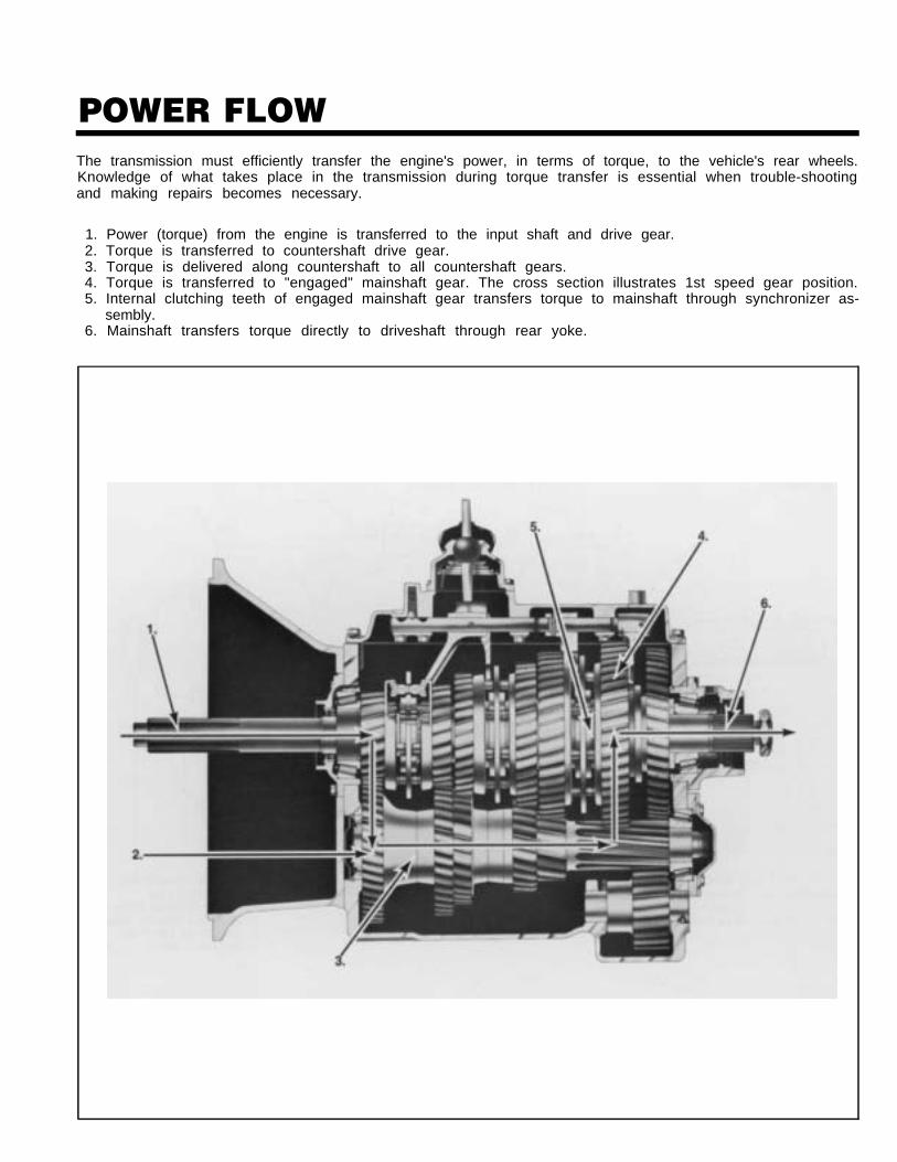
POWER FLOWThe transmission must efficiently transfer the engine's power, in terms of torque, to the vehicle's rear wheels.Knowledge of what takes place in the transmission during torque transfer is essential when trouble-shootingand making repairs becomes necessary.
1. Power (torque) from the engine is transferred to the input shaft and drive gear.2. Torque is transferred to countershaft drive gear.3. Torque is delivered along countershaft to all countershaft gears.4. Torque is transferred to "engaged" mainshaft gear. The cross section illustrates 1st speed gear position.5. Internal clutching teeth of engaged mainshaft gear transfers torque to mainshaft through synchronizer as-
sembly.6. Mainshaft transfers torque directly to driveshaft through rear yoke.
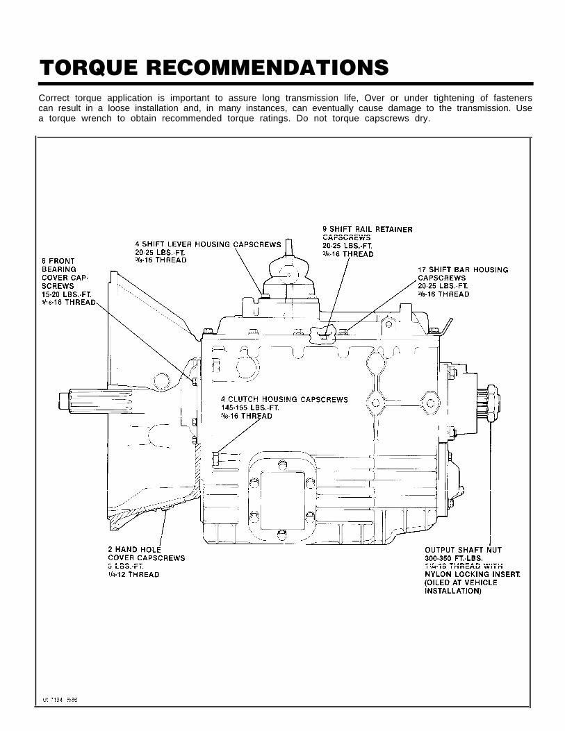
TORQUE RECOMMENDATIONSCorrect torque application is important to assure long transmission life, Over or under tightening of fastenerscan result in a loose installation and, in many instances, can eventually cause damage to the transmission. Usea torque wrench to obtain recommended torque ratings. Do not torque capscrews dry.
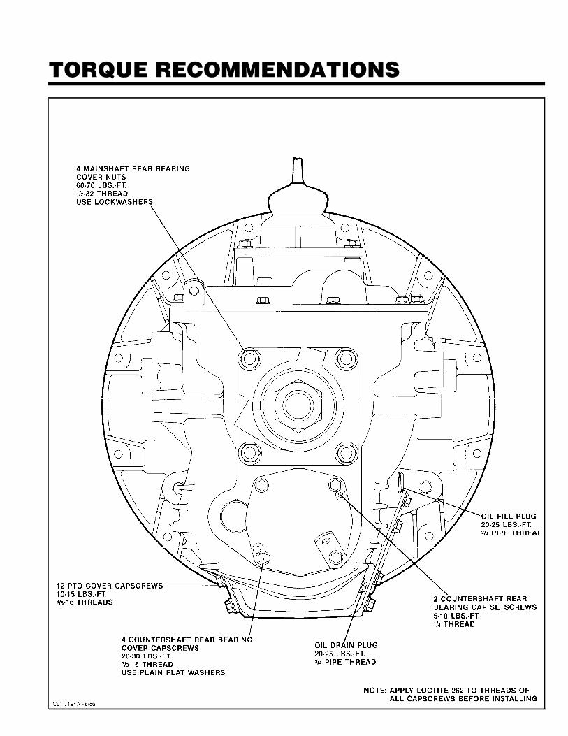
TORQUE RECOMMENDATIONS
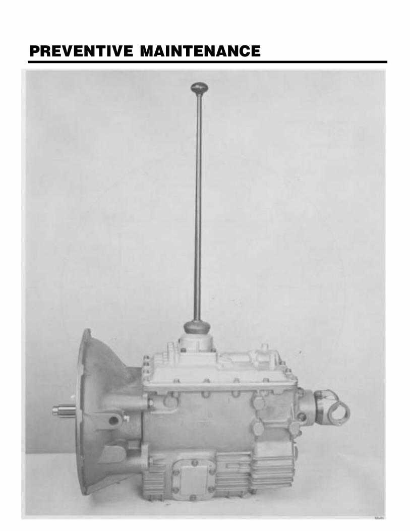
PREVENTIVE MAINTENANCE
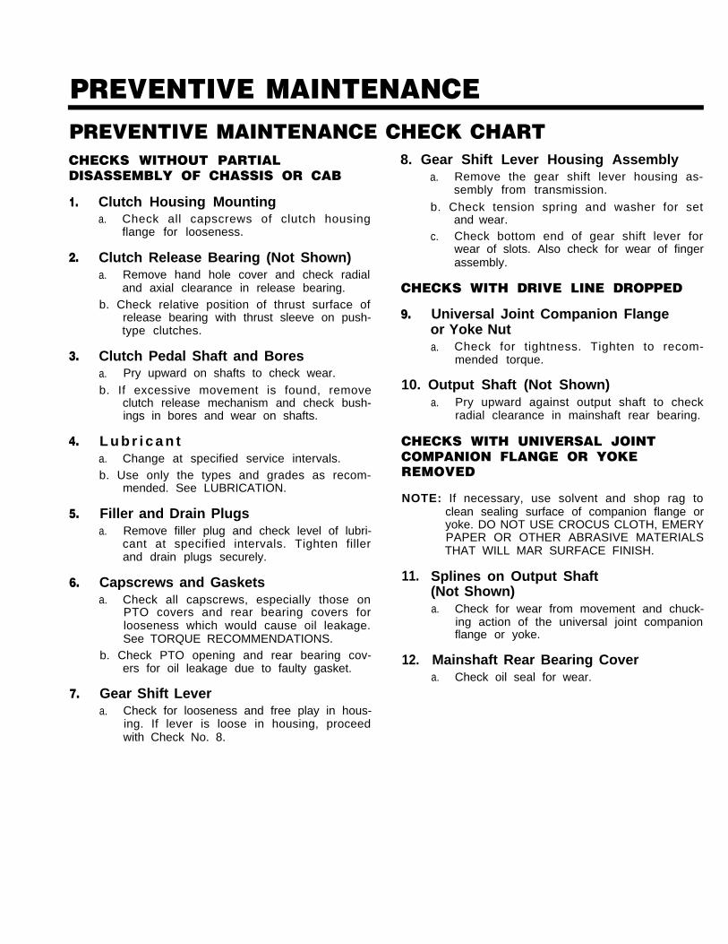
PREVENTIVE MAINTENANCEPREVENTIVE MAINTENANCE CHECK CHARTCHECKS WITHOUT PARTIALDISASSEMBLY OF CHASSIS OR CAB
1.
2.
3.
4.
5.
6.
7.
Clutch Housing Mountinga. Check all capscrews of clutch housing
flange for looseness.
Clutch Release Bearing (Not Shown)a. Remove hand hole cover and check radial
and axial clearance in release bearing.b. Check relative position of thrust surface of
release bearing with thrust sleeve on push-type clutches.
Clutch Pedal Shaft and Boresa. Pry upward on shafts to check wear.
b. If excessive movement is found, removeclutch release mechanism and check bush-ings in bores and wear on shafts.
L u b r i c a n ta. Change at specified service intervals.b. Use only the types and grades as recom-
mended. See LUBRICATION.
Filler and Drain Plugsa. Remove filler plug and check level of lubri-
cant at specified intervals. Tighten fillerand drain plugs securely.
Capscrews and Gasketsa. Check all capscrews, especially those on
PTO covers and rear bearing covers forlooseness which would cause oil leakage.See TORQUE RECOMMENDATIONS.
b. Check PTO opening and rear bearing cov-ers for oil leakage due to faulty gasket.
Gear Shift Levera. Check for looseness and free play in hous-
ing. If lever is loose in housing, proceedwith Check No. 8.
8. Gear Shift Lever Housing Assemblya. Remove the gear shift lever housing as-
sembly from transmission.
b. Check tension spring and washer for setand wear.
c. Check bottom end of gear shift lever forwear of slots. Also check for wear of fingerassembly.
CHECKS WITH DRIVE LINE DROPPED
9. Universal Joint Companion Flangeor Yoke Nuta. Check for tightness. Tighten to recom-
mended torque.
10. Output Shaft (Not Shown)a. Pry upward against output shaft to check
radial clearance in mainshaft rear bearing.
CHECKS WITH UNIVERSAL JOINTCOMPANION FLANGE OR YOKEREMOVED
NOTE: If necessary, use solvent and shop rag to
11.
12.
clean sealing surface of companion flange oryoke. DO NOT USE CROCUS CLOTH, EMERYPAPER OR OTHER ABRASIVE MATERIALSTHAT WILL MAR SURFACE FINISH.
Splines on Output Shaft(Not Shown)a. Check for wear from movement and chuck-
ing action of the universal joint companionflange or yoke.
Mainshaft Rear Bearing Covera. Check oil seal for wear.
PRECAUTIONSDisassemblyIt is assumed in the detailed assembly instructions that the lubricant has been drained from transmission, thenecessary linkage disconnected and the transmission has been removed from vehicle chassis. Removal of thegear shift lever housing assembly is included in the detailed instructions (Disassembly and Reassembly—Shift-ing Controls); however, this assembly must be detached from shift bar housing before transmission can be re-moved.
FOLLOW CLOSELY EACH PROCEDURE IN THE DETAILED INSTRUCTIONS. MAKING USE OF THE TEXT.ILLUSTRATIONS AND PHOTOGRAPHS PROVIDED.
1.
2.
3.
BEARINGS — Carefully wash and relubricate allreusable bearings as removed and protectivelywrap unti l ready for use. Remove bearingsplanned to be reused with pullers designed forthis purpose.
ASSEMBLIES — When disassembling the variousassemblies, such as the mainshaft, countershafts,and shift bar housing, lay all parts on a cleanbench in the same sequence as removed. Thisprocedure will simplify reassembly and reduce thepossibility of losing parts.
SNAP RINGS — Remove snap rings with pliers de-
/ ,
4. CLEANLINESS — Provide a clean place to work. It isimportant that no dirt or foreign material enters theunit during repairs. Dirt is an abrasive and can dam-age bearings. It is always good practice to clean theoutside of the unit before starting the planned dis-assembly.
5. WHEN USING TOOLS TO MOVE PARTS — Alwaysapply force to shafts, housings, etc, with restraint.Movement of some parts is restricted. Never applyforce to the part being driven after it stops solidly.The use of soft hammers, bars and mauls for all dis-assembly work is recommended.
signed for this purpose. Snap rings removed in thismanner can be reused, if they are not sprung orloose.
InspectionBefore reassembling the transmission, check each part carefully for abnormal or excessive wear and damage todetermine reuse or replacement. When replacement is necessary, use only genuine Fuller Transmission parts toassure continued performance and extended life from your unit.
Since the cost of a new part is generally a small fraction of the total cost of downtime and labor, avoid reusinga questionable part which could lead to additional repairs and expense soon after initial reassembly. To aid in de-termining the reuse or replacement of any transmission part, consideration should also be given to the unit’s his-tory, mileage, application, etc.
Recommended inspection procedures are provided in the following checklist.
A. BEARINGS B. GEARS1. Wash all bearings in clean solvent. Check 1.
balls, rollers and raceways for pitting, discolor-ation, and spalled areas. Replace bearings thatare pitted, discolored, spalled, or damagedduring disassembly.
2. Lubricate bearings that are not pitted, discol-ored, or spalled and check for axial and radialclearances.
Replace bearings with excessive clearances.2.
3. Check bearing fits. Bearing inner races shouldbe tight to shaft; outer races slightly tight toslightly loose in case bore. If bearing spinsfreely in bore, however, case should be re-placed.
Check gear teeth for frosting and pitting.Frosting of gear tooth faces present no threatof transmission failure. Often in continuedoperation of the unit, frosted gears will “heal”and not progress to the pitting stage. In mostcases, gears with light to moderate pittedteeth have considerable gear life remainingand can be reused, but gears with advancedstage pitting should be replaced.
Check for gears with clutching teeth abnor-mally worn, tapered, or reduced in length fromclashing in shifting. Replace gears found inany of these conditions.
PRECAUTIONSInspection (cont’d.)
c.
D.
E.
F.
G.
H.
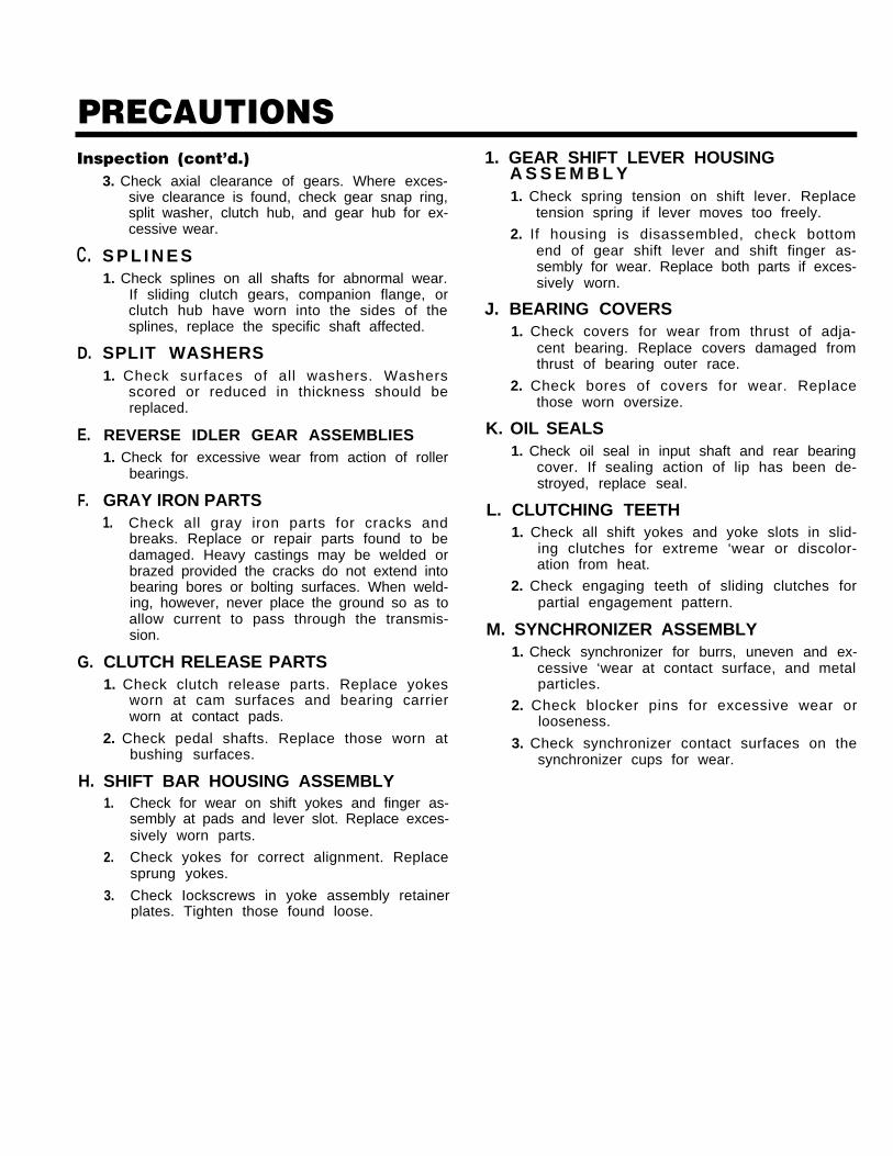
3. Check axial clearance of gears. Where exces-sive clearance is found, check gear snap ring,split washer, clutch hub, and gear hub for ex-cessive wear.
S P L I N E S1. Check splines on all shafts for abnormal wear.
If sliding clutch gears, companion flange, orclutch hub have worn into the sides of thesplines, replace the specific shaft affected.
SPLIT WASHERS1. Check surfaces of all washers. Washers
scored or reduced in thickness should bereplaced.
REVERSE IDLER GEAR ASSEMBLIES1. Check for excessive wear from action of roller
bearings.
GRAY IRON PARTS1. Check all gray iron parts for cracks and
breaks. Replace or repair parts found to bedamaged. Heavy castings may be welded orbrazed provided the cracks do not extend intobearing bores or bolting surfaces. When weld-ing, however, never place the ground so as toallow current to pass through the transmis-sion.
CLUTCH RELEASE PARTS1. Check clutch release parts. Replace yokes
worn at cam surfaces and bearing carrierworn at contact pads.
2. Check pedal shafts. Replace those worn atbushing surfaces.
SHIFT BAR HOUSING ASSEMBLY1.
2.
3.
Check for wear on shift yokes and finger as-sembly at pads and lever slot. Replace exces-sively worn parts.
Check yokes for correct alignment. Replacesprung yokes.
Check Iockscrews in yoke assembly retainerplates. Tighten those found loose.
1. GEAR SHIFT LEVER HOUSINGA S S E M B L Y1. Check spring tension on shift lever. Replace
tension spring if lever moves too freely.
2. If housing is disassembled, check bottomend of gear shift lever and shift finger as-sembly for wear. Replace both parts if exces-sively worn.
J. BEARING COVERS1. Check covers for wear from thrust of adja-
cent bearing. Replace covers damaged fromthrust of bearing outer race.
2. Check bores of covers for wear. Replacethose worn oversize.
K. OIL SEALS1. Check oil seal in input shaft and rear bearing
cover. If sealing action of lip has been de-stroyed, replace seaI.
L. CLUTCHING TEETH1. Check all shift yokes and yoke slots in slid-
ing clutches for extreme ‘wear or discolor-ation from heat.
2. Check engaging teeth of sliding clutches forpartial engagement pattern.
M. SYNCHRONIZER ASSEMBLY1. Check synchronizer for burrs, uneven and ex-
cessive ‘wear at contact surface, and metalparticles.
2. Check blocker pins for excessive wear orlooseness.
3. Check synchronizer contact surfaces on thesynchronizer cups for wear.
PRECAUTIONSReassemblyMake sure that interiors of case and housings are clean. It is important that dirt and other foreign materials bekept out of the transmission during reassembly. Dirt is an abrasive and can damage polished surfaces ofbearings and washers. Use certain precautions, as listed below, during reassembly.
1.
2.
3.
4.
G A S K E T S — Use new gaskets throughout thetransmission as it is being rebuilt. Make sure allgaskets are installed. An omission of any gasketcan result in oil leakage or misalignment ofbearing covers. Install PTO and shift bar housinggaskets dry.
CAPSCREWS — TO prevent oil leakage and loosen-ing, use Loctite 262 thread sealant on all cap-sc rews. For torque rat ings, see TORQUERECOMMENDATIONS.
SHIMS — Apply a light coat of Loctite 510 to both sides of shims before final installation to prevent leakage.
ASSEMBLY — Refer to the illustrations provided inthe detailed disassembly instructions as a guideto reassembly.
5.
6.
7.
INITIAL LUBRICATION — Coat all thrust washers,synchronizers, and bearings with transmission lu-bricant during reassembly to prevent damageduring initial start up.
END PLAY — Maintain .006 -.010 end play on coun-tershaft and mainshaft assemblies.
BEARINGS — Use of a sleeve type driver that con-tacts the inner race of the bearing is recom-mended to prevent damage to the rollers andcage.
UNIVERSAL JOINT COMPANION FLANGE ORYOKE — Pull the companion flange or yoke intoplace with the output shaft nut, using 300-350foot-pounds (407-475 N.m) of torque. Make surethe speedometer drive gear or a replacement spa-cer has been installed. Failure to properly torque
8.
the nut can result in damage to the mainshaftrear bearing.
IMPORTANT: REFER TO THE APPROPRIATE ILLUSTRATED PARTS LIST (SPECl-FIED BY MODEL SERIES) TO ENSURE THAT PROPER PARTS AREUSED DURING REASSEMBLY OF THE TRANSMISSION.
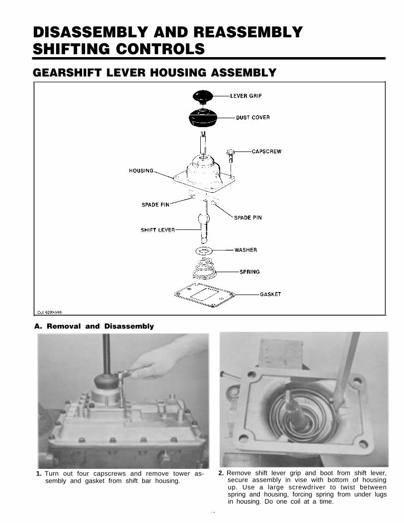
DISASSEMBLY AND REASSEMBLYSHIFTING CONTROLSGEARSHIFT LEVER HOUSING ASSEMBLY
A. Removal and Disassembly
1. Turn out four capscrews and remove tower as-sembly and gasket from shift bar housing.
2. Remove shift lever grip and boot from shift lever,secure assembly in vise with bottom of housingup. Use a large screwdriver to twist betweenspring and housing, forcing spring from under lugsin housing. Do one coil at a time.
15

DISASSEMBLY AND REASSEMBLYSHIFTING CONTROLSGEARSHIFT LEVER HOUSING ASSEMBLY (con't.)
3. Remove tension spring, washer and gearshift leverfrom housing. 4. Remove spade pins from bore in housing.
B. Reassembly of Gearshift Lever Housing Assembly
16-04
16-02
2. Position gearshift lever in housing with spade pinsin lever ball slot and install tension spring washerover ball, dished side up.
1. With gearshift lever housing secured in vise asduring disassembly, install spade pins in bore ofhousing.
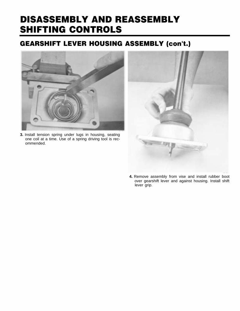
DISASSEMBLY AND REASSEMBLYSHIFTING CONTROLSGEARSHIFT LEVER HOUSING ASSEMBLY (con't.)
3. Install tension spring under lugs in housing, seatingone coil at a time. Use of a spring driving tool is rec-ommended.
4. Remove assembly from vise and install rubber bootover gearshift lever and against housing. Install shiftlever grip.
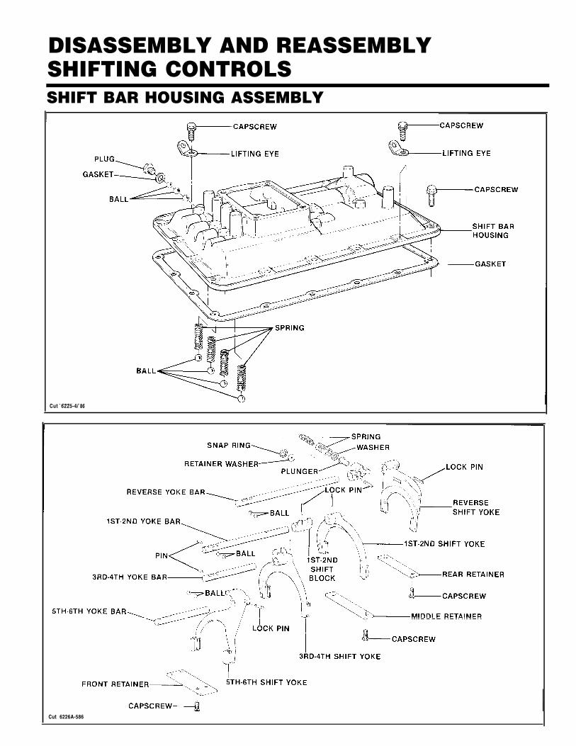
DISASSEMBLY AND REASSEMBLYSHIFTING CONTROLSSHIFT BAR HOUSING ASSEMBLY
Cut 6225-4/ 86
Cut 6226A-586
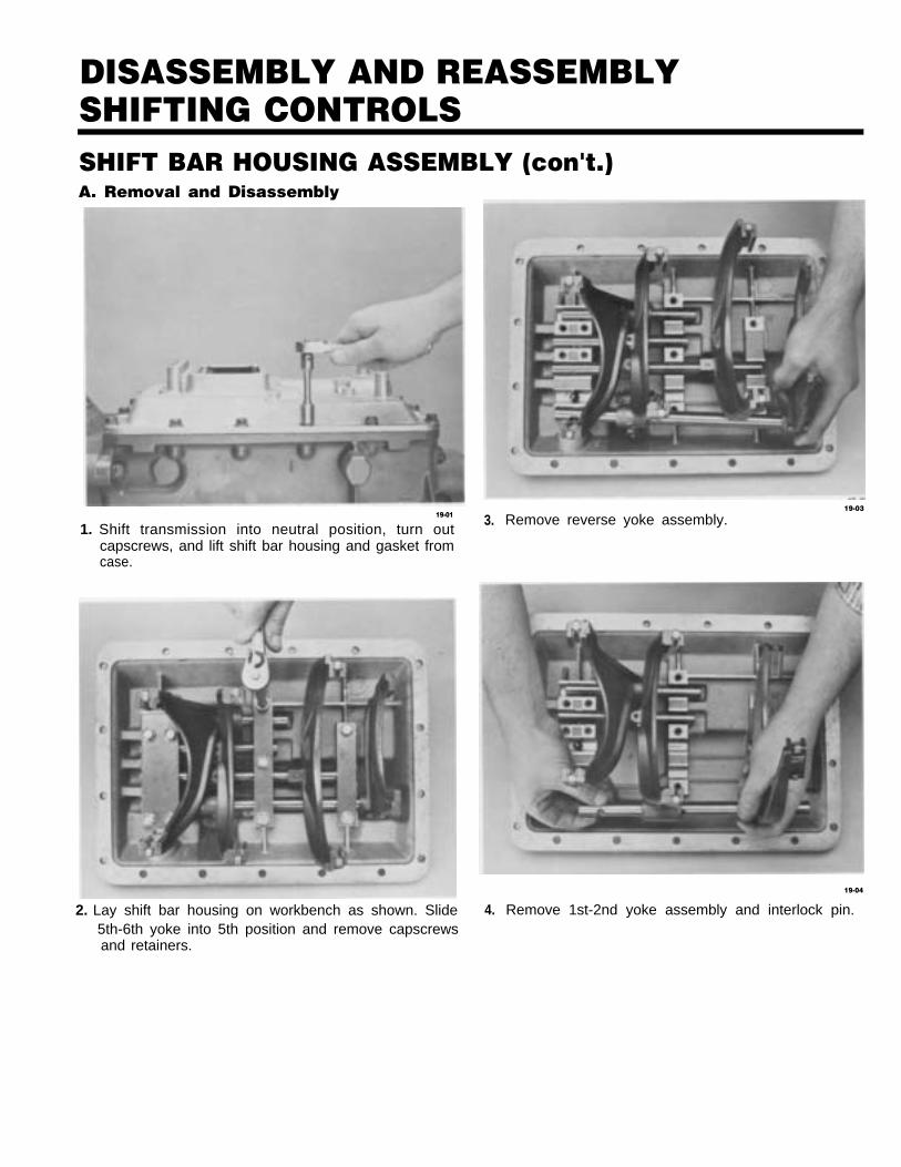
DISASSEMBLY AND REASSEMBLYSHIFTING CONTROLSSHIFT BAR HOUSING ASSEMBLY (con't.)A. Removal and Disassembly
19-01
1. Shift transmission into neutral position, turn out3.
capscrews, and lift shift bar housing and gasket fromcase.
2. Lay shift bar housing on workbench as shown. Slide 4.
19-03
Remove reverse yoke assembly.
19-04
Remove 1st-2nd yoke assembly and interlock pin.5th-6th yoke into 5th position and remove capscrewsand retainers.
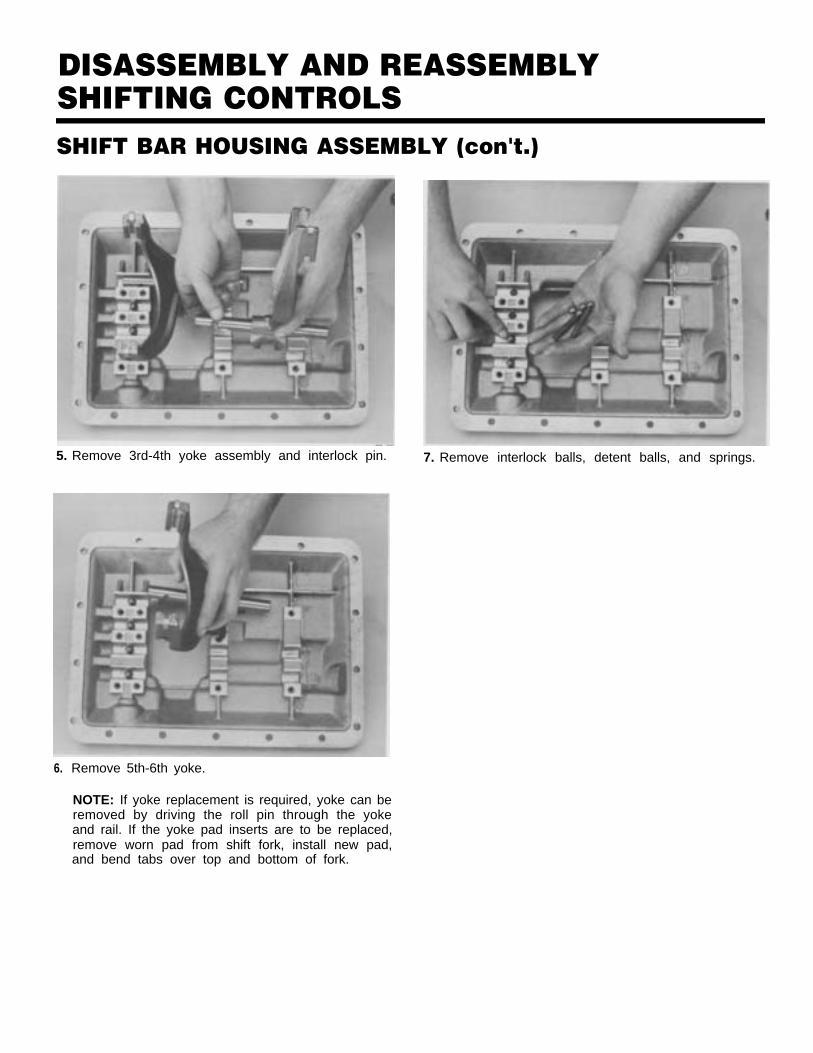
DISASSEMBLY AND REASSEMBLYSHIFTING CONTROLSSHIFT BAR HOUSING ASSEMBLY (con't.)
5. Remove 3rd-4th yoke assembly and interlock pin. 7. Remove interlock balls, detent balls, and springs.
6. Remove 5th-6th yoke.
NOTE: If yoke replacement is required, yoke can beremoved by driving the roll pin through the yokeand rail. If the yoke pad inserts are to be replaced,remove worn pad from shift fork, install new pad,and bend tabs over top and bottom of fork.
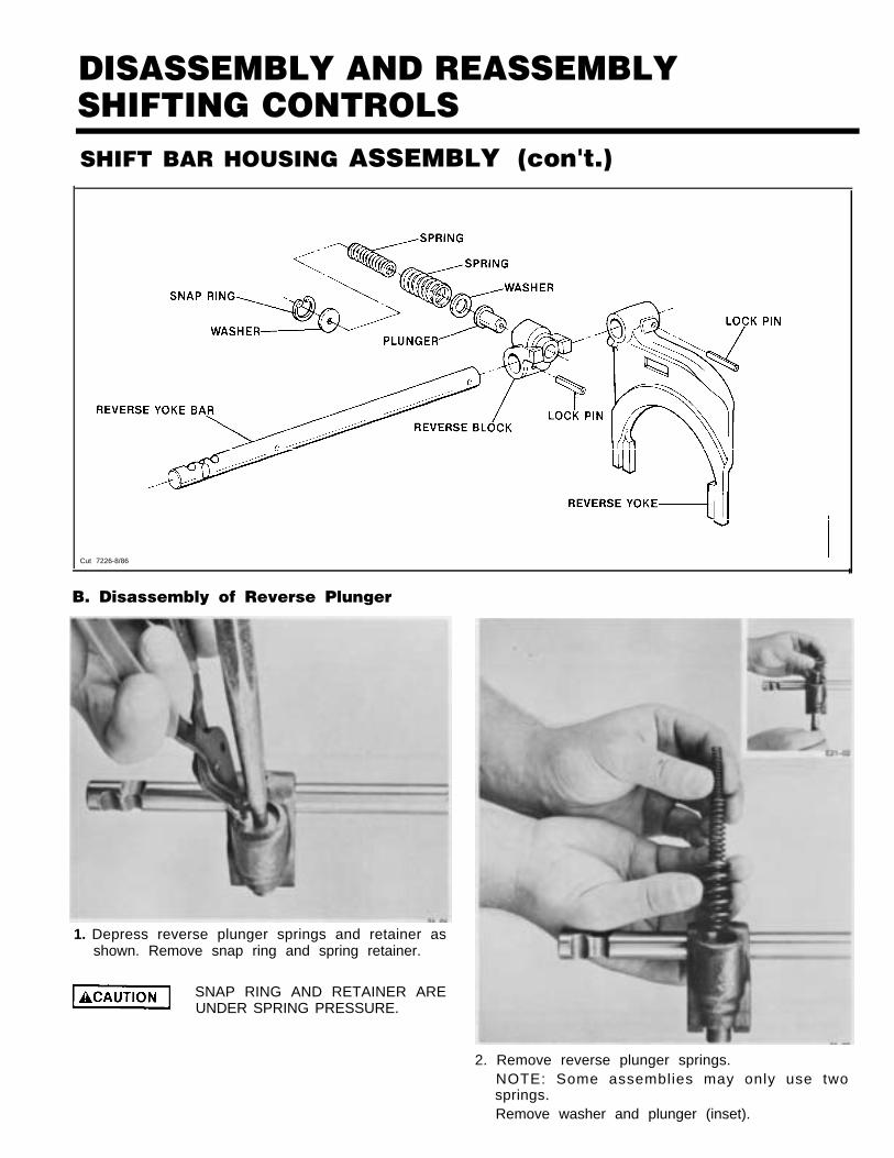
DISASSEMBLY AND REASSEMBLYSHIFTING CONTROLSSHIFT BAR HOUSING ASSEMBLY (con't.)
Cut 7226-8/86I
B. Disassembly of Reverse Plunger
1. Depress reverse plunger springs and retainer asshown. Remove snap ring and spring retainer.
SNAP RING AND RETAINER AREUNDER SPRING PRESSURE.
2. Remove reverse plunger springs.NOTE: Some assemblies may only use twosprings.Remove washer and plunger (inset).

DISASSEMBLY AND REASSEMBLYSHIFTING CONTROLSSHIFT BAR HOUSING ASSEMBLY (conÍ t.)C. Reassembly of Reverse Plunger Assembly
22-01
1. Install plunger and washer as shown and installreverse plunger springs (inset).
D. Reassembly of Shift Bar Housing
22-02
2. Depress reverse plunger retainer and springs andinstall snap ring in groove of shift block.
Cut 7226A-8/86
1. Install interlock balls, detent balls and springs in install 3rd and 4th detent spring and ball. Positionthe following sequence; position (3) balls in the re- (2) balls in adjacent cross bore and install 5th andverse light switch bore and install reverse detent 6th detent spring and ball.spring and ball. Position (2) balls in adjacent cross NOTE: Balls and springs can be used interchan-bore and install 1st and 2nd detent spring and geably.ball. Position (2) balls in adjacent cross bore and
DISASSEMBLY AND REASSEMBLYSHIFTING CONTROLSSHIFT BAR HOUSING ASSEMBLY (conÕt.)
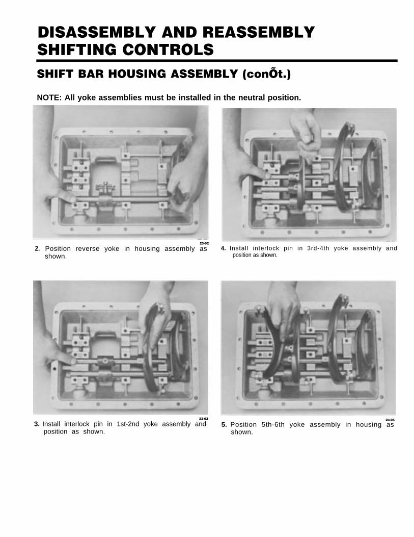
NOTE: All yoke assemblies must be installed in the neutral position.
2.23-02
Position reverse yoke in housing assembly asshown.
4. Install interlock pin in 3rd-4th yoke assembly andposition as shown.
23-03
3. Install interlock pin in 1st-2nd yoke assembly andposition as shown.
23-05
5. Position 5th-6th yoke assembly in housing asshown.
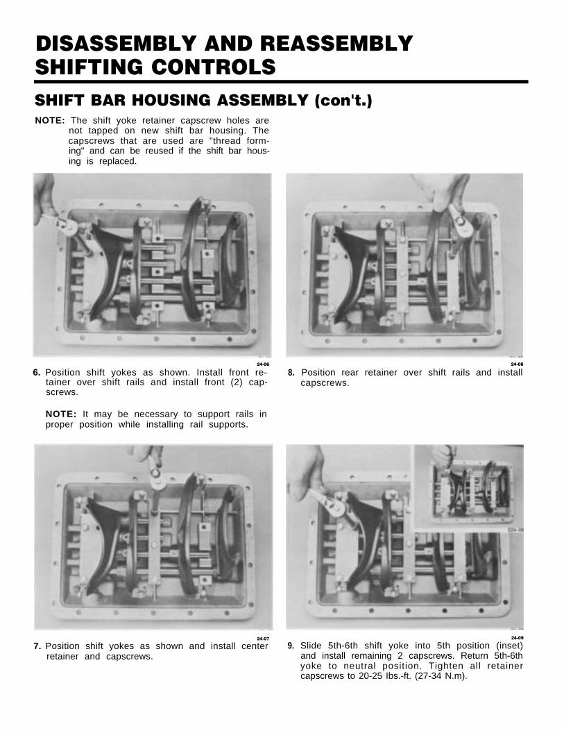
DISASSEMBLY AND REASSEMBLYSHIFTING CONTROLSSHIFT BAR HOUSING ASSEMBLY (con't.)NOTE: The shift yoke retainer capscrew holes are
not tapped on new shift bar housing. Thecapscrews that are used are "thread form-ing" and can be reused if the shift bar hous-ing is replaced.
24-06
6. Position shift yokes as shown. Install front re-tainer over shift rails and install front (2) cap-screws.
NOTE: It may be necessary to support rails inproper position while installing rail supports.
24-07
7. Position shift yokes as shown and install centerretainer and capscrews.
8.
9.
24-08
Position rear retainer over shift rails and installcapscrews.
24-09
Slide 5th-6th shift yoke into 5th position (inset)and install remaining 2 capscrews. Return 5th-6thyoke to neutral position. Tighten all retainercapscrews to 20-25 Ibs.-ft. (27-34 N.m).
REMOVAL - YOKE AND CLUTCH HOUSING
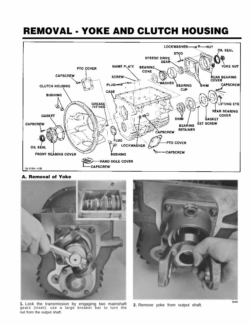
A. Removal of Yoke
1. Lock the transmission by engaging two mainshaft25-02
2. Remove yoke from output shaft.gears ( inset). use a large breaker bar to turn thenut from the output shaft.
REMOVAL - YOKE AND CLUTCH HOUSING
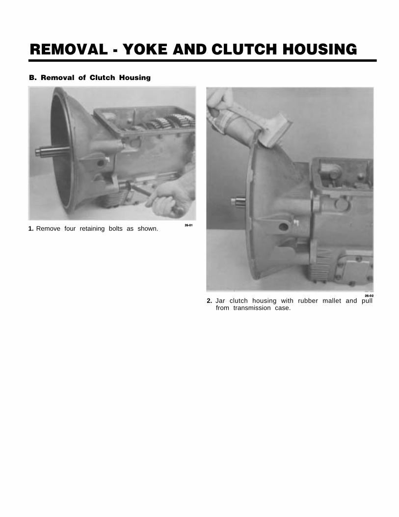
B. Removal of Clutch Housing
1. Remove four retaining bolts as shown.26-01
26-02
2. Jar clutch housing with rubber mallet and pullfrom transmission case.
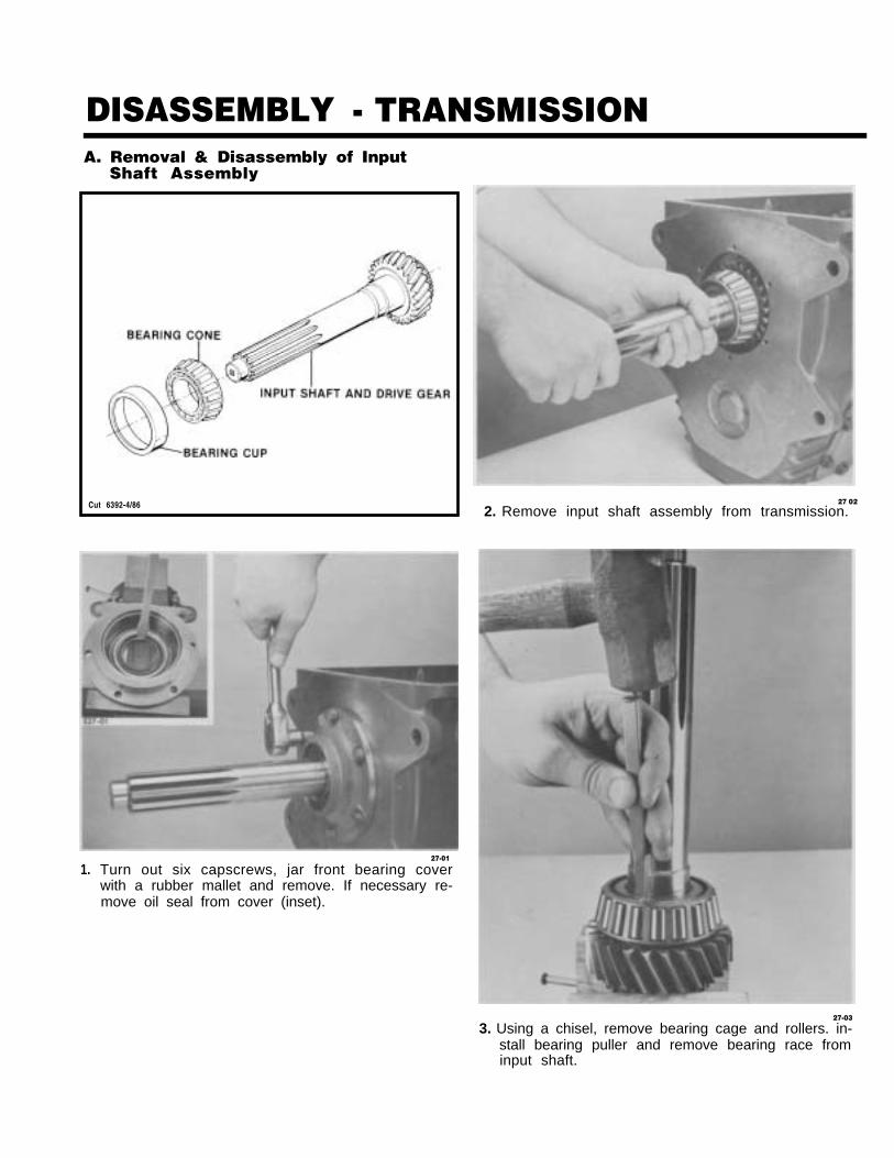
DISASSEMBLY - TRANSMISSIONA. Removal & Disassembly of Input
Shaft Assembly
Cut 6392-4/86
1.27-01
Turn out six capscrews, jar front bearing coverwith a rubber mallet and remove. If necessary re-move oil seal from cover (inset).
27 02
2. Remove input shaft assembly from transmission.
27-03
3. Using a chisel, remove bearing cage and rollers. in-stall bearing puller and remove bearing race frominput shaft.
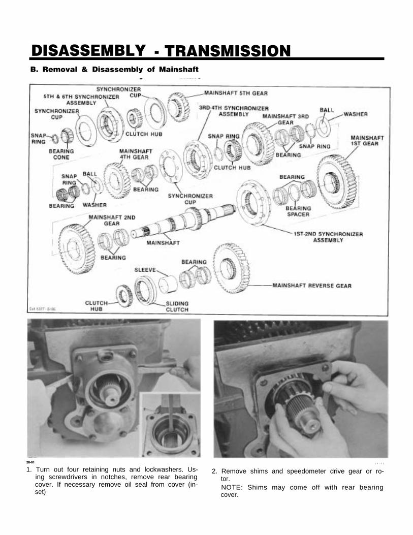
DISASSEMBLY - TRANSMISSIONB. Removal & Disassembly of Mainshaft
28-01 2 8 - 0 2
1. Turn out four retaining nuts and lockwashers. Us- 2. Remove shims and speedometer drive gear or ro-ing screwdrivers in notches, remove rear bearing tor.cover. If necessary remove oil seal from cover (in- NOTE: Shims may come off with rear bearingset) cover.
DISASSEMBLY - TRANSMISSION
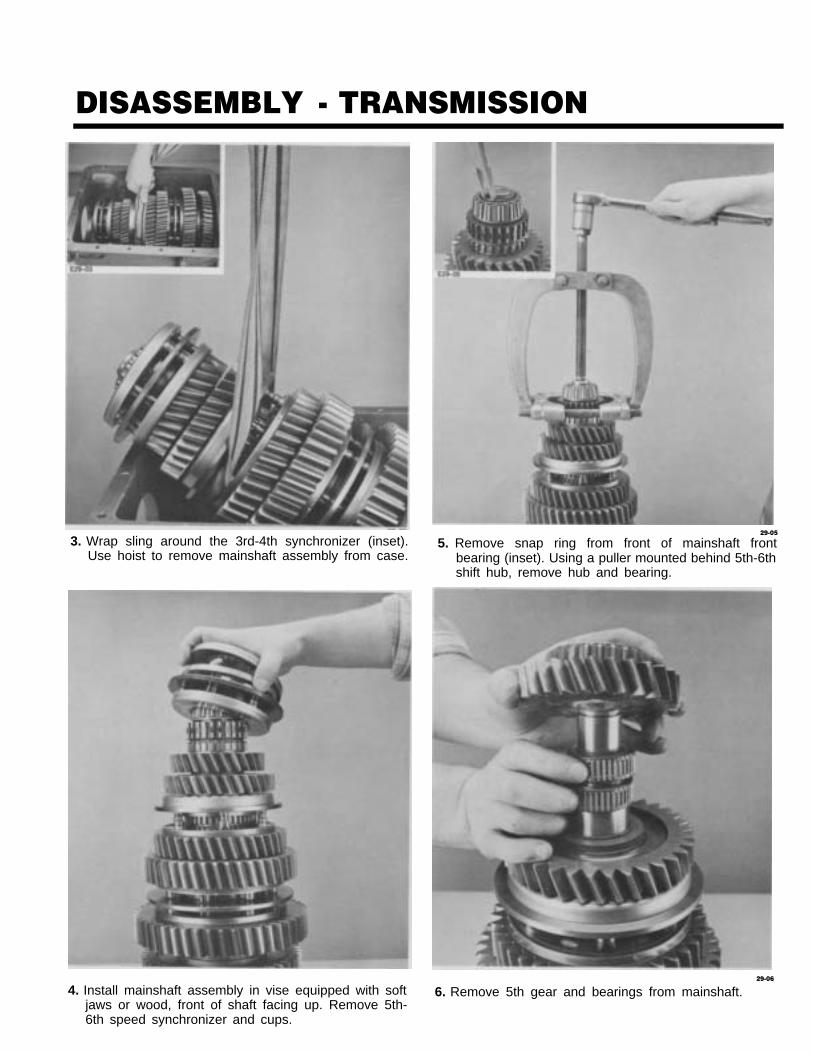
3. Wrap sling around the 3rd-4th synchronizer (inset).Use hoist to remove mainshaft assembly from case.
4. Install mainshaft assembly in vise equipped with softjaws or wood, front of shaft facing up. Remove 5th-6th speed synchronizer and cups.
29-05
5. Remove snap ring from front of mainshaft frontbearing (inset). Using a puller mounted behind 5th-6thshift hub, remove hub and bearing.
29-06
6. Remove 5th gear and bearings from mainshaft.
DISASSEMBLY - TRANSMISSION
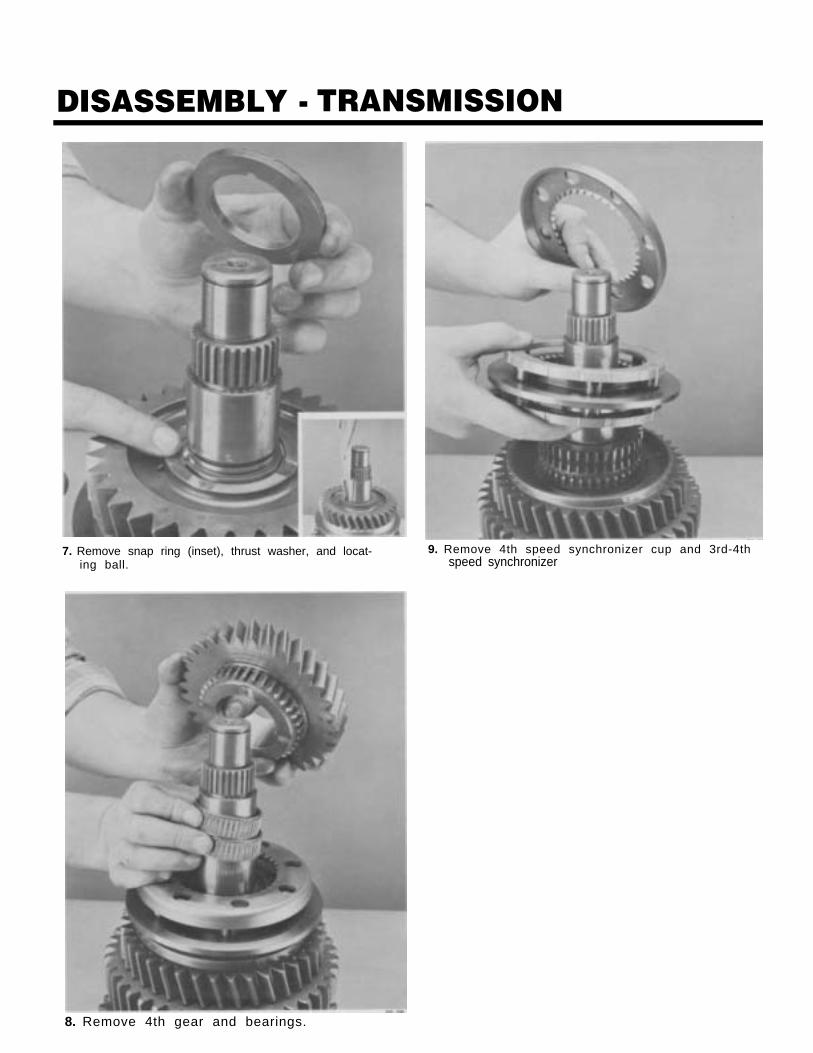
7. Remove snap ring (inset), thrust washer, and locat- 9. Remove 4th speed synchronizer cup and 3rd-4thing ball. speed synchronizer
8. Remove 4th gear and bearings.

DISASSEMBLY - TRANSMISSION
10. Remove snap ring (inset) and 3rd-4th shift hub. 12. Remove snap ring (inset), thrust washer and locat-ing ball.
11. Remove 3rd gear and bearings from mainshaft. 13. Remove 2nd gear and bearings from mainshaft.

DISASSEMBLY - TRANSMISSION
14. Remove 1st-2nd speed synchronizer.
32-15
15. Reposition mainshaft in vise, rear of shaft facing
16. Using a puller (inset), remove reverse gear, spacer,and rear bearing.
Remove reversesliding clutch.
32-17
gear bearings and reverse gearup.
DISASSEMBLY - TRANSMISSION
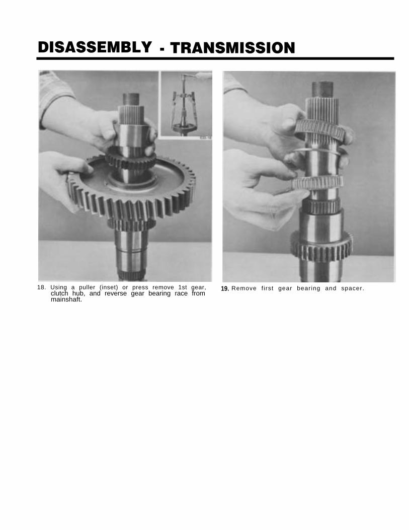
18. Using a puller (inset) or press remove 1st gear, 19. Remove f i rst gear bearing and spacer.clutch hub, and reverse gear bearing race frommainshaft.
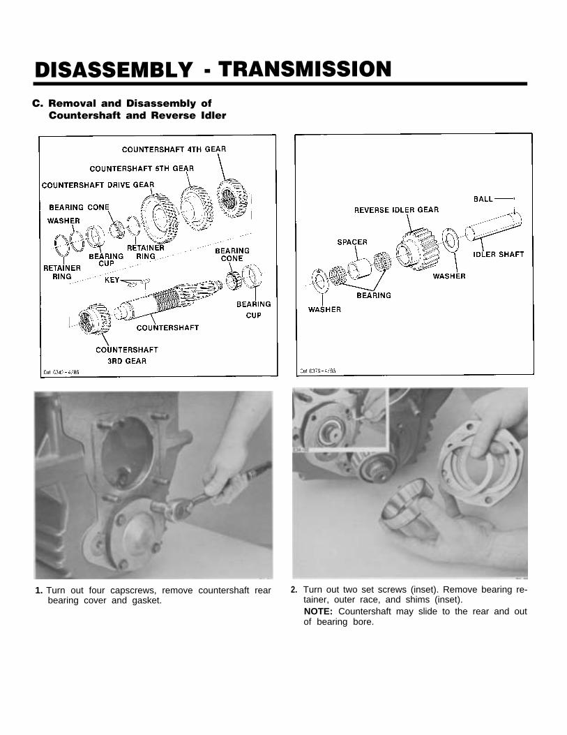
DISASSEMBLY - TRANSMISSIONC. Removal and Disassembly of
Countershaft and Reverse Idler
1. Turn out four capscrews, remove countershaft rearbearing cover and gasket.
2. Turn out two set screws (inset). Remove bearing re-tainer, outer race, and shims (inset).NOTE: Countershaft may slide to the rear and outof bearing bore.
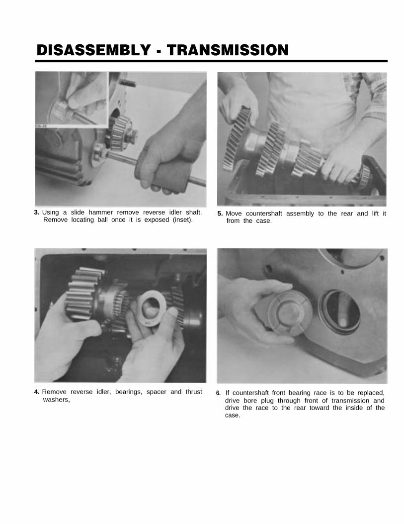
DISASSEMBLY - TRANSMISSION
3. Using a slide hammer remove reverse idler shaft.Remove locating ball once it is exposed (inset).
4. Remove reverse idler, bearings, spacer and thrustwashers,
5. Move countershaft assembly to the rear and lift itfrom the case.
6. If countershaft front bearing race is to be replaced,drive bore plug through front of transmission anddrive the race to the rear toward the inside of thecase.
DISASSEMBLY - TRANSMISSION
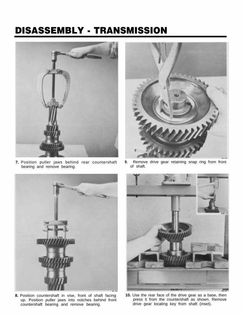
7. Position puller jaws behind rear countershaftbearing and remove bearing.
8. Position countershaft in vise, front of shaft facingup. Position puller jaws into notches behind frontcountershaft bearing and remove bearing.
9. Remove drive gear retaining snap ring from frontof shaft.
10. Use the rear face of the drive gear as a base, thenpress it from the countershaft as shown. Removedrive gear locating key from shaft (inset).
DISASSEMBLY - TRANSMISSION
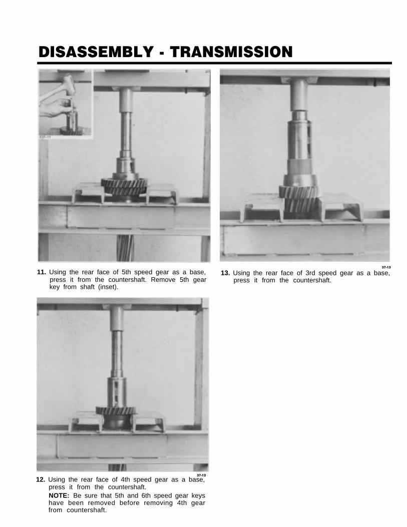
11. Using the rear face of 5th speed gear as a base,press it from the countershaft. Remove 5th gearkey from shaft (inset).
37-13
13. Using the rear face of 3rd speed gear as a base,press it from the countershaft.
37-12
12. Using the rear face of 4th speed gear as a base,press it from the countershaft.NOTE: Be sure that 5th and 6th speed gear keyshave been removed before removing 4th gearfrom countershaft.
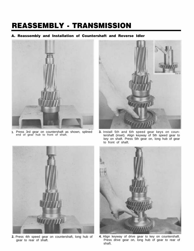
REASSEMBLY - TRANSMISSIONA. Reassembly and Installation of Countershaft and Reverse Idler
1. Press 3rd gear on countershaft as shown, splined 3. Install 5th and 6th speed gear keys on coun-end of gear hub to front of shaft. tershaft (inset). Align keyway of 5th speed gear to
key on shaft. Press 5th gear on, long hub of gearto front of shaft.
2. Press 4th speed gear on countershaft, long hub of 4. Align keyway of drive gear to key on countershaft.gear to rear of shaft. Press drive gear on, long hub of gear to rear of
shaft.
REASSEMBLY - TRANSMISSION
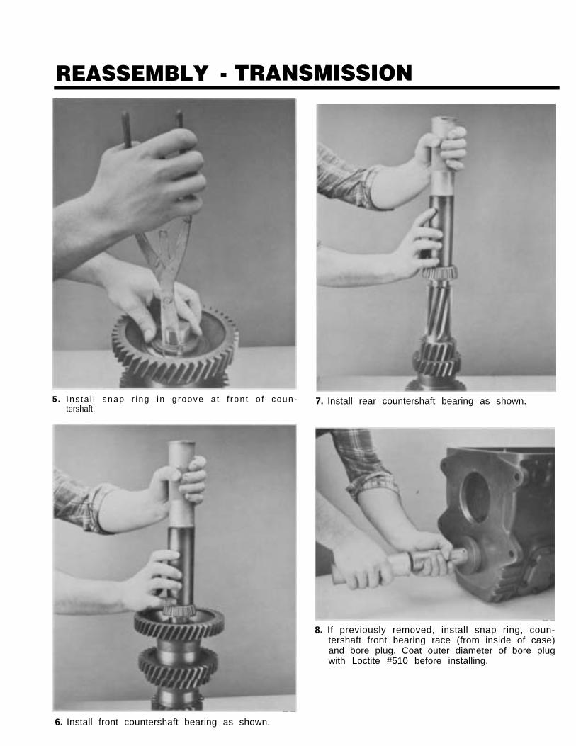
5. I ns ta l l snap r i ng i n g roove a t f r on t o f coun - 7. Install rear countershaft bearing as shown.tershaft.
8. If previously removed, install snap ring, coun-tershaft front bearing race (from inside of case)and bore plug. Coat outer diameter of bore plugwith Loctite #510 before installing.
6. Install front countershaft bearing as shown.
REASSEMBLY - TRANSMISSION
40.09
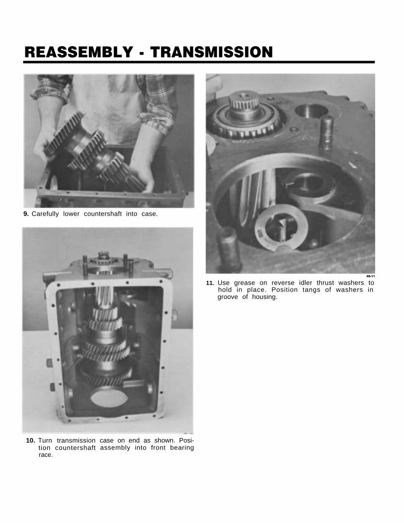
9. Carefully lower countershaft into case.
10. Turn transmissiontion countershaftrace.
case on end as shown. Posi-assembly into front bearing
40-11
11. Use grease on reverse idler thrust washers tohold in place. Position tangs of washers ingroove of housing.
REASSEMBLY - TRANSMISSION
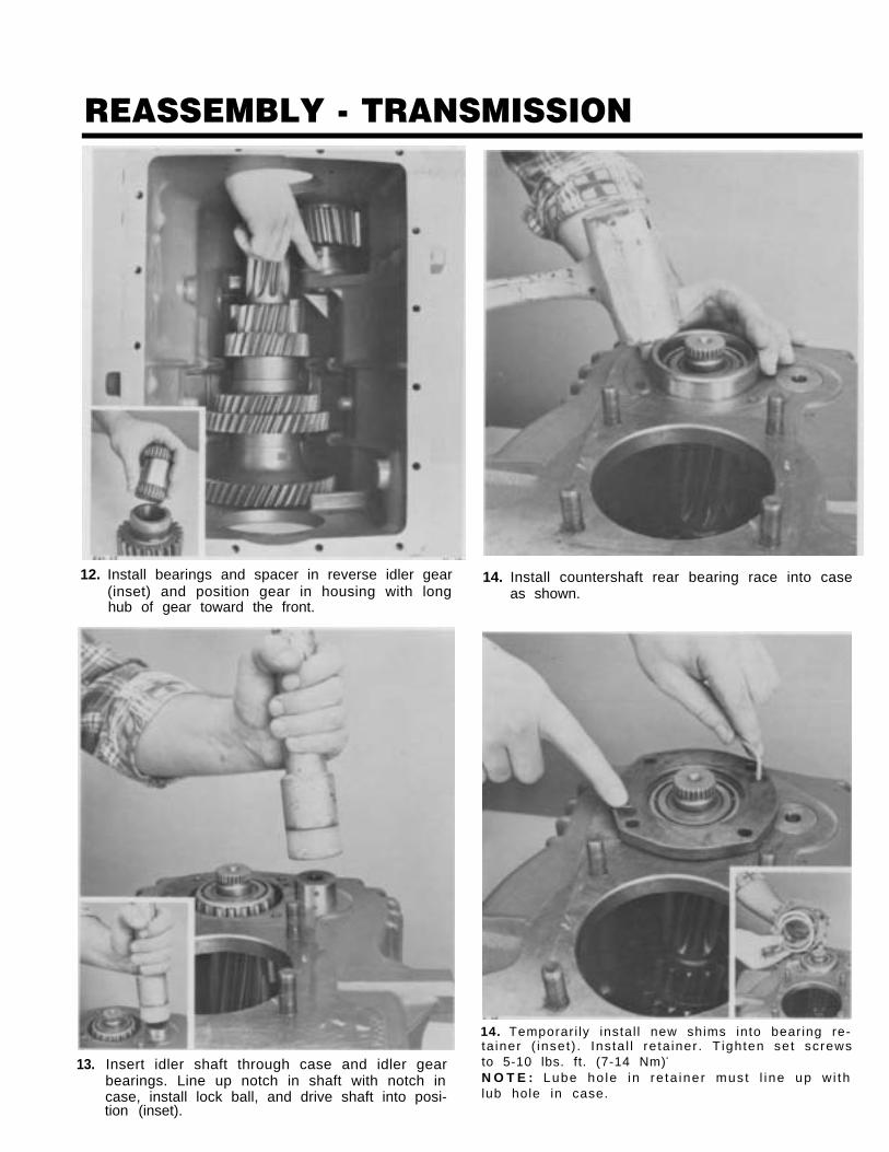
12. Install bearings and spacer in reverse idler gear(inset) and position gear in housing with longhub of gear toward the front.
13. Insert idler shaft through case and idler gearbearings. Line up notch in shaft with notch incase, install lock ball, and drive shaft into posi-tion (inset).
14. Install countershaft rear bearing race into caseas shown.
14. Temporari ly instal l new shims into bearing re-ta iner ( inset) . Insta l l re ta iner . T ighten set screwsto 5-10 lbs. ft. (7-14 Nm).
N O T E : Lube ho le in re ta iner must l ine up w i thlub hole in case.
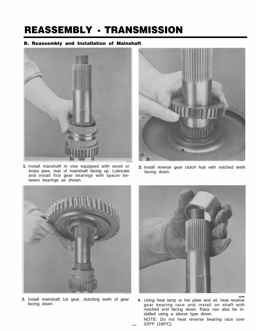
REASSEMBLY - TRANSMISSIONB. Reassembly and Installation of Mainshaft
1. Install manshaft in vise equipped with wood orbrass jaws, rear of mainshaft facing up. Lubricateand install first gear bearings with spacer be-tween bearings as shown.
2. Install mainshaft 1st gear, clutching teeth of gearfacing down.
43
3. Install reverse gear clutch hub with notched teethfacing down.
4.43-04
Using heat lamp or hot plate and oil, heat reversegear bearing race and install on shaft withnotched end facing down. Race can also be in-stalled using a sleeve type driver.NOTE: Do not heat reverse bearing race over320oF (160oC).
REASSEMBLY - TRANSMISSION
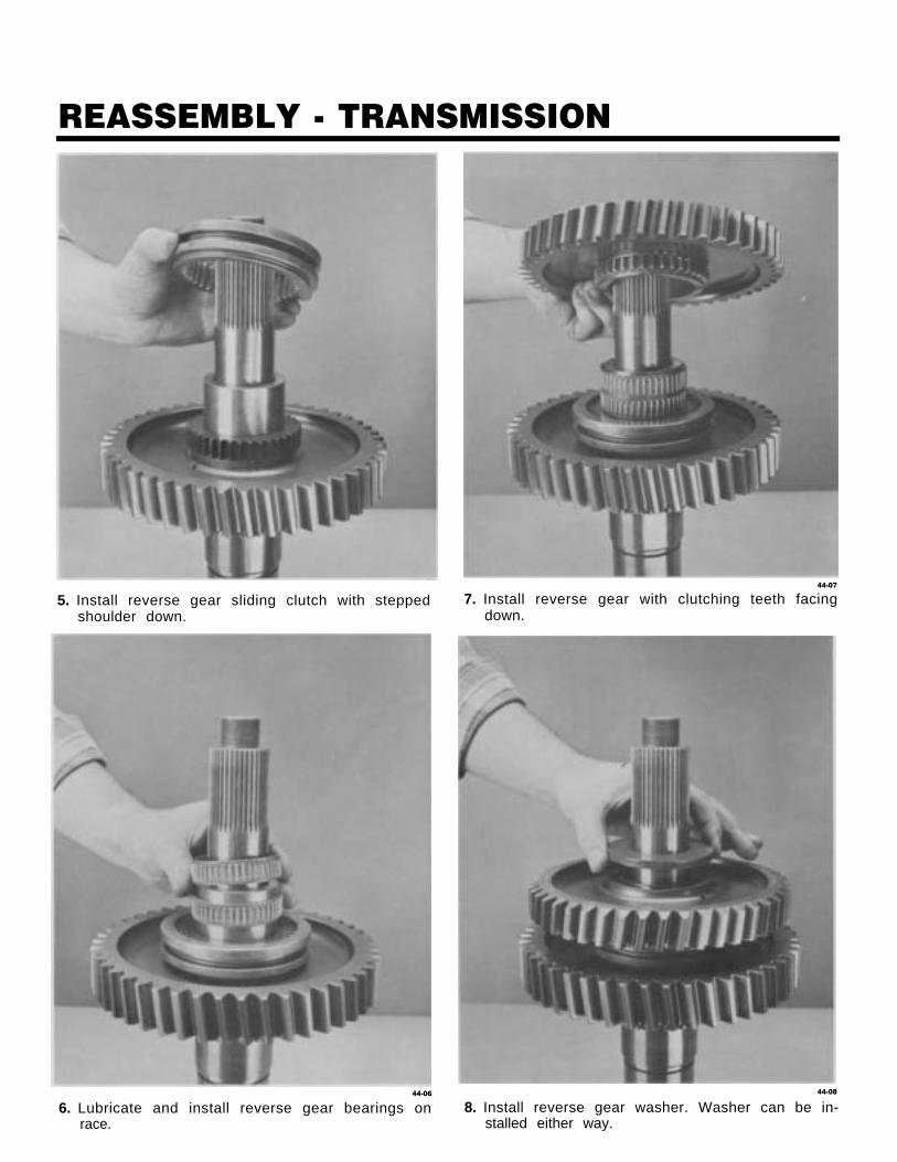
5. Install reverse gear sliding clutch with steppedshoulder down.
44-06
6. Lubricate and install reverse gear bearings onrace.
44-07
7. Install reverse gear with clutching teeth facingdown.
44-08
8. Install reverse gear washer. Washer can be in-stalled either way.
REASSEMBLY - TRANSMISSION
45-09
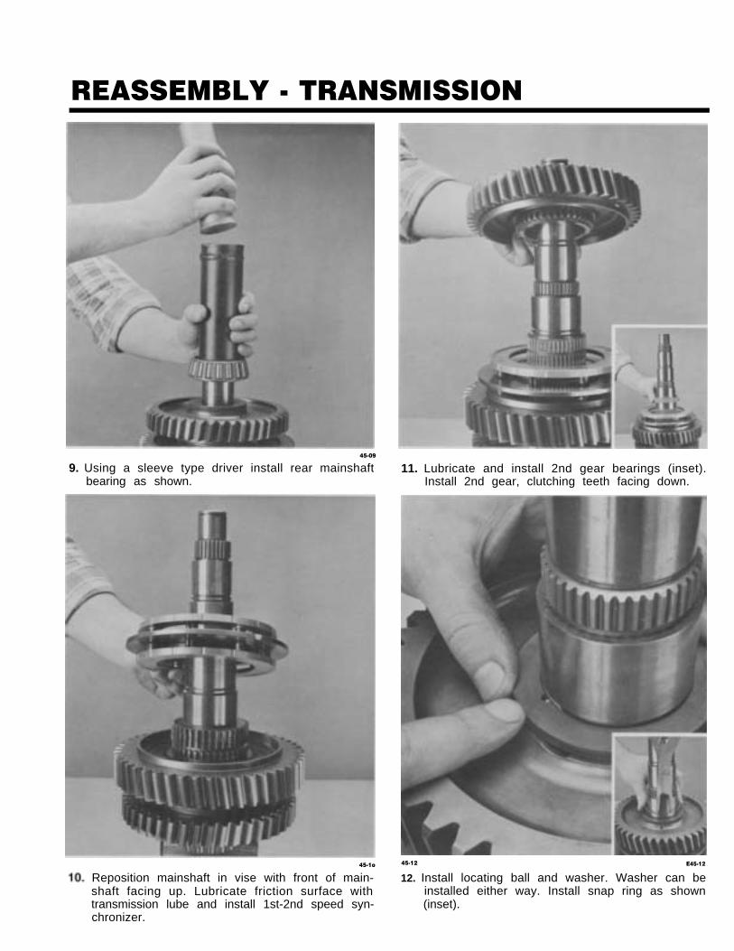
9. Using a sleeve type driver install rear mainshaftbearing as shown.
45-1o
Reposition mainshaft in vise with front of main-shaft facing up. Lubricate friction surface withtransmission lube and install 1st-2nd speed syn-chronizer.
11. Lubricate and install 2nd gear bearings (inset).Install 2nd gear, clutching teeth facing down.
45-12 E45-12
12. Install locating ball and washer. Washer can beinstalled either way. Install snap ring as shown(inset).
REASSEMBLY - TRANSMISSION
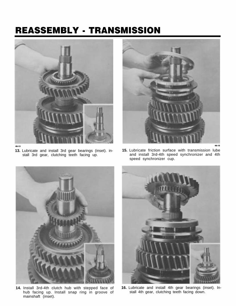
46-13
13. Lubricate and install 3rd gear bearings (inset). in-stall 3rd gear, clutching teeth facing up.
14. Install 3rd-4th clutch hub with stepped face ofhub facing up. Install snap ring in groove ofmainshaft (inset).
46-15
15. Lubricate friction surface with transmission lubeand install 3rd-4th speed synchronizer and 4thspeed synchronizer cup.
16. Lubricate and install 4th gear bearings (inset). ln-stall 4th gear, clutching teeth facing down.
REASSEMBLY - TRANSMISSION
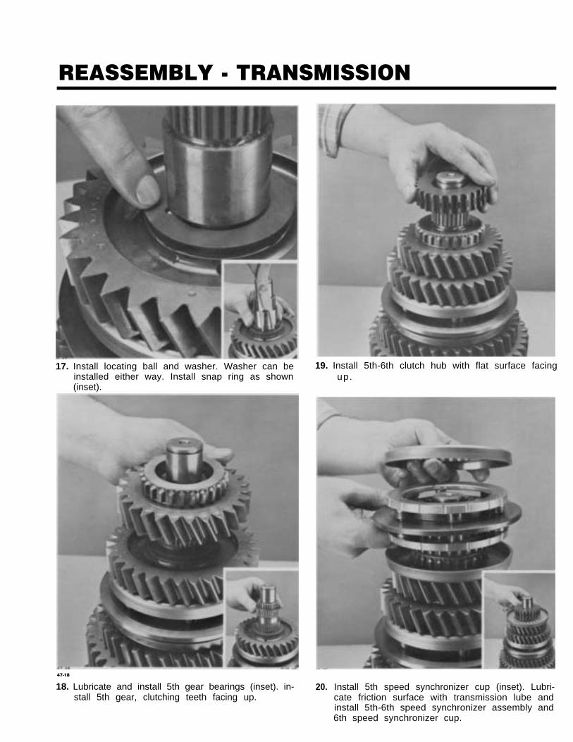
17. Install locating ball and washer. Washer can beinstalled either way. Install snap ring as shown(inset).
19. Install 5th-6th clutch hub with flat surface facingup.
47-18
18. Lubricate and install 5th gear bearings (inset). in-stall 5th gear, clutching teeth facing up.
20. Install 5th speed synchronizer cup (inset). Lubri-cate friction surface with transmission lube andinstall 5th-6th speed synchronizer assembly and6th speed synchronizer cup.

REASSEMBLY - TRANSMISSION
21. Using a sleeve type driver install frontbearing. Install snap ring in grooveshaft (inset).
mainshafton end of
22. Remove mainshaft assembly from vise and placeon bench. Shift synchronizer into 4th gear.
23. Using a sling around the 3rd-4th synchronizercarefully lower mainshaft into case.
48-24
24. Using a sleeve type driver install bearing on in-put shaft.
REASSEMBLY - TRANSMISSION
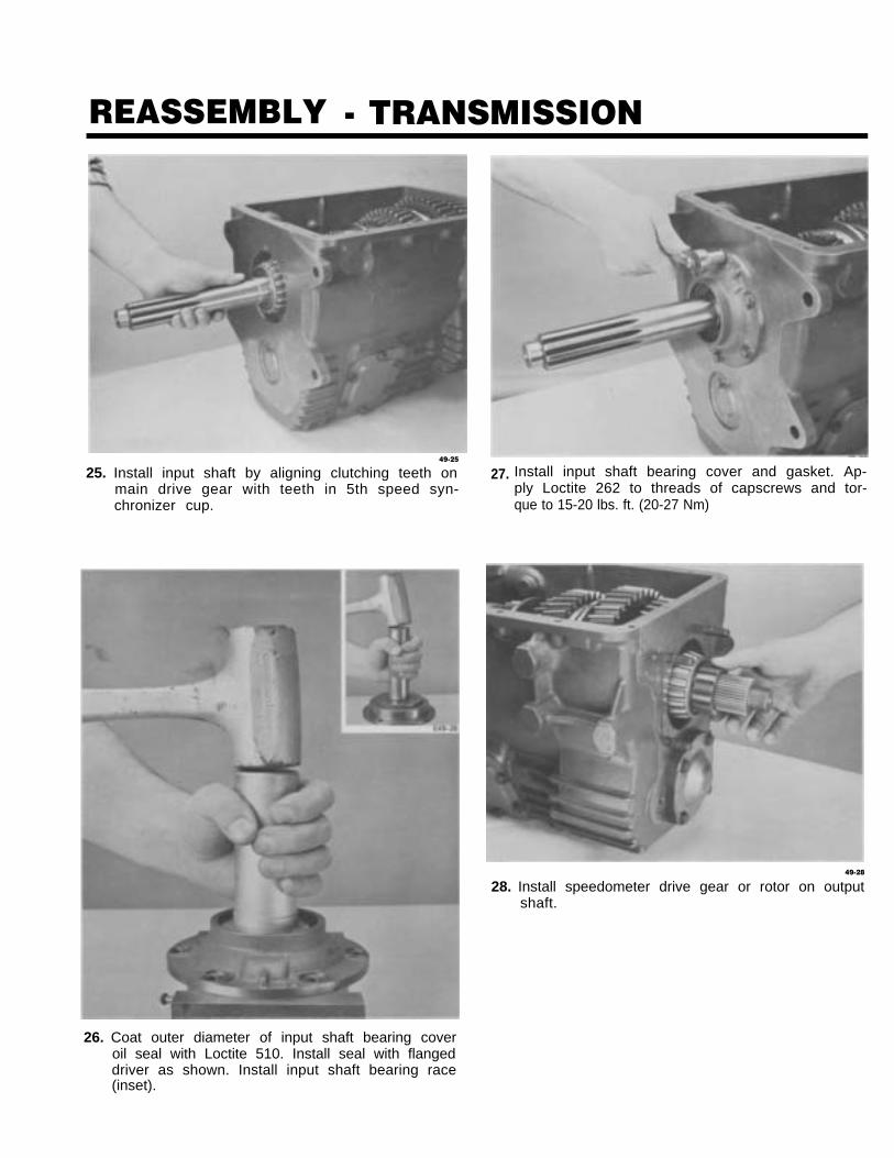
49-25
25. Install input shaft by aligning clutching teeth onmain drive gear with teeth in 5th speed syn-
Install input shaft bearing cover and gasket. Ap-ply Loctite 262 to threads of capscrews and tor-que to 15-20 lbs. ft. (20-27 Nm)chronizer cup.
27.
49-28
28. Install speedometer drive gear or rotor on outputshaft.
26. Coat outer diameter of input shaft bearing coveroil seal with Loctite 510. Install seal with flangeddriver as shown. Install input shaft bearing race(inset).
REASSEMBLY - TRANSMISSION
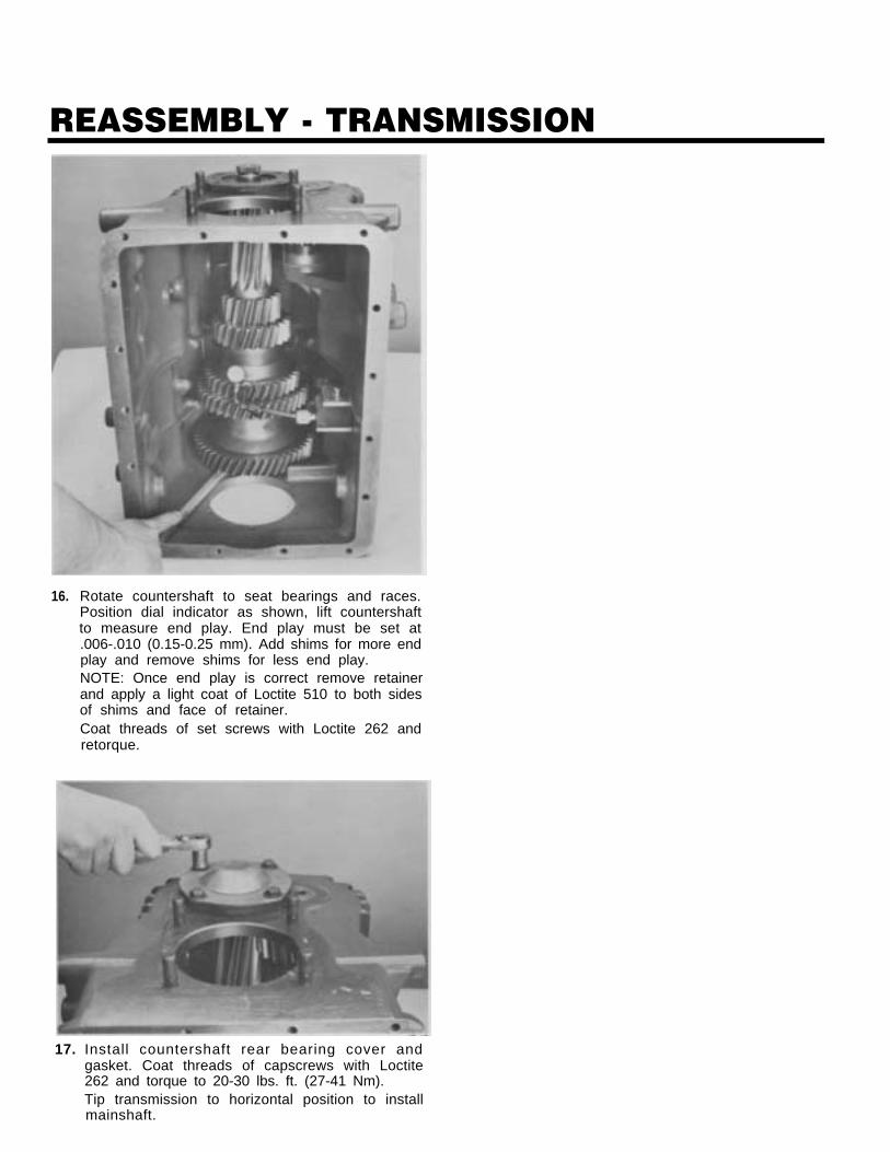
16. Rotate countershaft to seat bearings and races.Position dial indicator as shown, lift countershaftto measure end play. End play must be set at.006-.010 (0.15-0.25 mm). Add shims for more endplay and remove shims for less end play.NOTE: Once end play is correct remove retainerand apply a light coat of Loctite 510 to both sidesof shims and face of retainer.Coat threads of set screws with Loctite 262 andretorque.
17. Install countershaft rear bearing cover andgasket. Coat threads of capscrews with Loctite262 and torque to 20-30 lbs. ft. (27-41 Nm).Tip transmission to horizontal position to installmainshaft.

REASSEMBLY - TRANSMISSION
29. If necessary install rear bearing race (inset). Tem-porarily install shims and rear bearing cover.Tighten nuts to 60-70 lbs. ft. (81-95 Nm).NOTE: Top of rear bearing cover is marked forproper installation.
30. Place transmission in a vertical position asshown. Install yoke and nut. Torque yoke nut to300-350 lbs. ft. (407-475 Nm). Rotate input shaftand mainshaft to seat bearings and races.
31. Position dial indicator as shown. Pry up on out-put shaft to measure end play. End play must beset at .006 -.010 (0.15-0.25 mm rein). Add shims formore end play, remove shims for less end play.NOTE: Once end play is correct remove yokeand rear bearing cover and apply a light coat ofLoctite 510 to both sides of shims.
32. Install rear seal using a flanged driver.
REASSEMBLY - TRANSMISSION
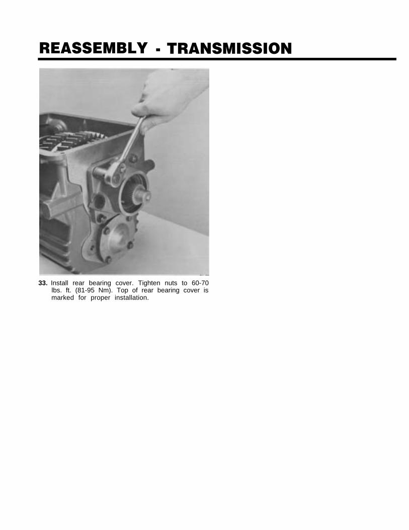
33. Install rear bearing cover. Tighten nuts to 60-70lbs. ft. (81-95 Nm). Top of rear bearing cover ismarked for proper installation.
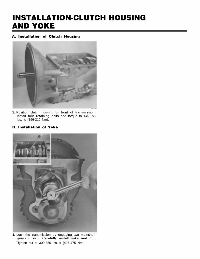
INSTALLATION-CLUTCH HOUSINGAND YOKEA. Installation of Clutch Housing
1. Position clutch housing onInstall four retaining boltslbs. ft. (196-210 Nm).
B. Installation of Yoke
52A-01
front of transmission.and torque to 145-155
1. Lock the transmission by engaging two mainshaftgears (inset). Carefully install yoke and nut.Tighten nut to 300-350 lbs. ft (407-475 Nm).
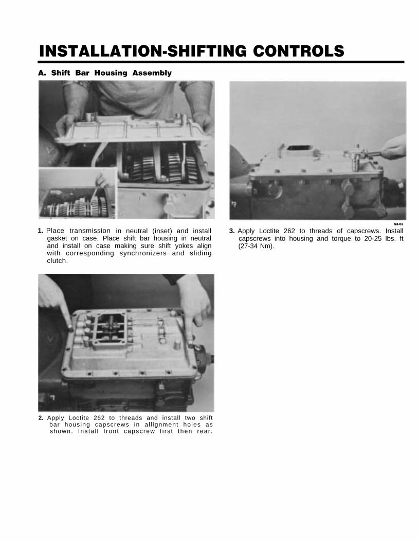
INSTALLATION-SHIFTING CONTROLSA. Shift Bar Housing Assembly
1. Place transmission in neutral (inset) and installgasket on case. Place shift bar housing in neutraland install on case making sure shift yokes alignwith corresponding synchronizers and slidingclutch.
53-03
3. Apply Loctite 262 to threads of capscrews. Installcapscrews into housing and torque to 20-25 lbs. ft(27-34 Nm).
2. Apply Loctite 262 to threads and install two shiftbar housing capscrews in a l l ignment holes asshown. Ins ta l l f ron t capscrew f i r s t then rear .
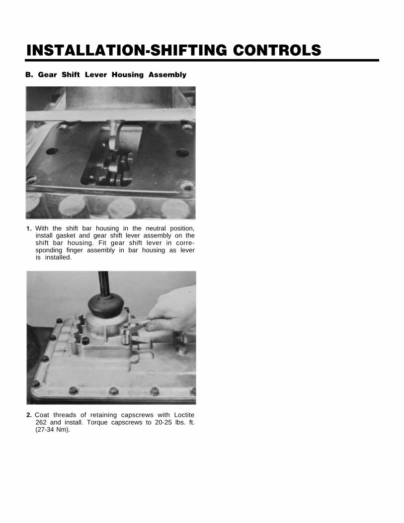
INSTALLATION-SHIFTING CONTROLSB. Gear Shift Lever Housing Assembly
With the shift bar housing in the neutral position,install gasket and gear shift lever assembly on theshift bar housing. Fit gear shift lever in corre-sponding finger assembly in bar housing as leveris installed.
2. Coat threads of retaining capscrews with Loctite262 and install. Torque capscrews to 20-25 lbs. ft.(27-34 Nm).

Copyright Eaton Corporation, 2012. Eaton hereby grant their customers, vendors, or distributors permission to freely copy, reproduce and/or distribute this document in printed format. It may be copied only in its entirety without any changes or modifications. THIS INFORMATION IS NOT INTENDED FOR SALE OR RESALE, AND THIS NOTICE MUST REMAIN ON ALL COPIES.
Note: Features and specifications listed in this document are subject to change without notice and represent the maximum capabilities of the software and products with all options installed. Although every attempt has been made to ensure the accuracy of information contained within, Eaton makes no representation about the completeness, correctness or accuracy and assumes no responsibility for any errors or omissions. Features and functionality may vary depending on selected options.
For spec’ing or service assistance, call 1-800-826-HELP (4357) or visit www.eaton.com/roadranger.In Mexico, call 001-800-826-4357.
Eaton CorporationVehicle GroupP.O. Box 4013Kalamazoo, MI 49003 USA800-826-HELP (4357)www.eaton.com/roadranger
Printed in USA
Roadranger: Eaton and trusted partners providing the best products and services in the industry, ensuring more time on the road.