full waveform digitizing airborne laser scanner for wide ......2015/03/24 · rriegliegl...
TRANSCRIPT
RIEGLRIEGL LMS-Q780 LMS-Q780Full Waveform Digitizing Airborne Laser Scanner for Wide Area Mapping
Airborne Laser Scanning
visit our website www.riegl.com
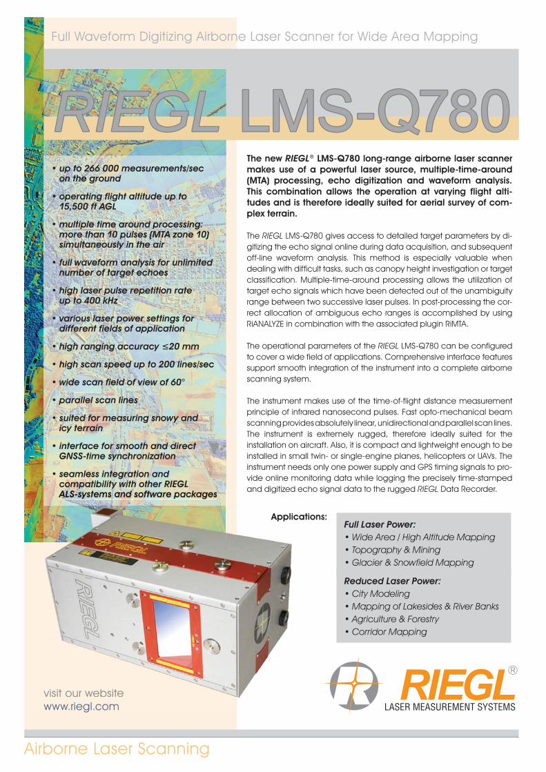
The new RIEGL® LMS-Q780 long-range airborne laser scanner makes use of a powerful laser source, multiple-time-around (MTA) processing, echo digitization and waveform analysis. This combination allows the operation at varying flight alti-tudes and is therefore ideally suited for aerial survey of com-plex terrain.
The RIEGL LMS-Q780 gives access to detailed target parameters by di-gitizing the echo signal online during data acquisition, and subsequent off-line waveform analysis. This method is especially valuable when dealing with difficult tasks, such as canopy height investigation or target classification. Multiple-time-around processing allows the utilization of target echo signals which have been detected out of the unambiguity range between two successive laser pulses. In post-processing the cor-rect allocation of ambiguous echo ranges is accomplished by using RiANALYZE in combination with the associated plugin RiMTA. The operational parameters of the RIEGL LMS-Q780 can be configured to cover a wide field of applications. Comprehensive interface features support smooth integration of the instrument into a complete airborne scanning system.
The instrument makes use of the time-of-flight distance measurement principle of infrared nanosecond pulses. Fast opto-mechanical beam scanning provides absolutely linear, unidirectional and parallel scan lines.The instrument is extremely rugged, therefore ideally suited for theinstallation on aircraft. Also, it is compact and lightweight enough to be installed in small twin- or single-engine planes, helicopters or UAVs. The instrument needs only one power supply and GPS timing signals to pro-vide online monitoring data while logging the precisely time-stamped and digitized echo signal data to the rugged RIEGL Data Recorder.
• up to 266 000 measurements/secon the ground
• operating flight altitude up to 15,500 ft AGL
• multiple time around processing: more than 10 pulses (MTA zone 10)simultaneously in the air
• full waveform analysis for unlimited number of target echoes
• high laser pulse repetition rateup to 400 kHz
• various laser power settings fordifferent fields of application
• high ranging accuracy ≤20 mm
• high scan speed up to 200 lines/sec
• wide scan field of view of 60°
• parallel scan lines
• suited for measuring snowy andicy terrain
• interface for smooth and directGNSS-time synchronization
• seamless integration and compatibility with other RIEGLALS-systems and software packages
visit our websitewww.riegl.com
and digitized ecALALALALALALALALALALALALALALALALALALLLALALALALALALALALALALALALALAALALALALALALALALALALALALALALALALLALLALALALALALALLALLALALLAALLALALALALS-S-S-S-S-S-SSSS-S-S-S-SS-S-S-SS-S-S-S-S-S-S-S-S-S-SS-S-S-S-S-S-SS-S-S-S-S-S-S-S-SS-S-S-S-S-S-S-S-SS-S-SS-S-S-S-S-S-SSS sysysysysysysysysysysysysysysysysysysysysysysysysysysyysysysysysysyysyysysysysysysysysysysyyysyssysyysysysysysysyysysysysysssysyyyyystststststststststststststststststststststststststtststststststststststststststsstsssststsssssttstememememememememememememememememememememememememememememmememmemememememmemmmmemmmmee sssss sssss ssssssssssss sssssss ss sss s anananananananananaanananannnnnnanannnnanannananaaanaannnanananaaanaanananananananaannannnnnanaand d dddd d ddd dd d dddddddddddd dd dddddddddddd ddddddddddddd ddddddddddddddddddd d sososososososososososososososososososossossssssossososossssososossosososossoooooftftftftftftftfftftftftftftftftftftftftffftftftftftftftftftftftffftffftftfttttfffftftftfftffffftfftftftftftftftftftftftfttftfffffffffff wwawwwawawawawawawawawawawwawwaawawawawwawawawwawawawawwwawwawawawaawawawawawwwwwwwww rererererererererererereerererererer ppppppppppppppacacacccacacacaaaa kakakakakakageggegegegesssssssssssssssss
Applications:Full Laser Power:
• Wide Area / High Altitude Mapping • Topography & Mining • Glacier & Snowfield Mapping
Reduced Laser Power: • City Modeling • Mapping of Lakesides & River Banks • Agriculture & Forestry • Corridor Mapping
11) Limitation for range measurement capability, does not considerlaser safety!
12) Standard deviation one sigma @ 250 m range under RIEGL testconditions.
13) Accuracy is the degree of conformity of a measured quantity to its actual (true) value.
14) Precision, also called reproducibility or repeatability, is the degree to which further measurements show the same result.
15) Measured at the 1/e2 points. 0.25 mrad correspond to an increase of 25 cm of beam diameter per 1000 m distance.
16) Practically limited only by the maximum data rate allowed for the RIEGL Data Recorder.
17) Minimum scan speed increasing linearly to 53 lines/sec @ 400 000 Hz PRR @ laser power ≥ 50%
18) Minimum scan speed increasing linearly to 27 lines/sec @ 400 000 Hz PRR @ laser power < 50%
19) Angle between consecutive laser shots, user adjustable
Full Laser Power
Reduced Laser Power
Technical Data RIEGL LMS-Q780
2
Laser Product Classification Class 3B Laser Product according to IEC60825-1:2007 The following clause applies for instruments delivered into the United States: Complies with 21 CFR 1040.10 and 1040.11 except for deviations pursuant to Laser Notice No. 50, dated June 24, 2007.
The instrument must be used only in combination with the appropriate laser safety box.
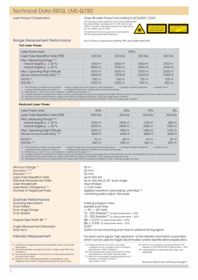
Range Measurement Performance as a function of laser power setting, PRR, and target reflectivity
Minimum Range 11) 50 mAccuracy 12) 13) 20 mmPrecision 12) 14) 20 mmLaser Pulse Repetition Rate up to 400 kHzEffective Measurement Rate up to 266 kHz @ 60° scan angleLaser Wavelength near infraredLaser Beam Divergence 15) ≤ 0.25 mradNumber of Targets per Pulse digitized waveform processing: unlimited 16)
monitoring data output: first pulse
Scanner PerformanceScanning Mechanism rotating polygon mirrorScan Pattern parallel scan linesScan Angle Range ± 30° = 60° totalScan Speed 14 - 200 lines/sec17) @ laser power level ≥ 50% 10 - 200 lines/sec18) @ laser power level < 50%Angular Step Width 19) ≥ 0.012° @ laser power level ≥ 50% ≥ 0.006° @ laser power level < 50%Angle Measurement Resolution 0.001°Scan Sync Option for synchronizing scan lines to external timing signal
Intensity Measurement For each echo signal, high-resolution 16-bit intensity information is provided which can be used for target discrimination and/or identification/classification.
<400 mW3 ns
1064 nm
Laser Power Level 100% Laser Pulse Repetition Rate (PRR) 100 kHz 200 kHz 300 kHz 400 kHzMax. Measuring Range 1) 3)
natural targets ≥ 20 % 4100 m 3500 m 3000 m 2700 m natural targets ≥ 60 % 5800 m 5100 m 4500 m 4100 mMax. Operating Flight Altitude 4700 m 4200 m 3700 m 3300 mAbove Ground Level (AGL) 2) 3) 15500 ft 13700 ft 12000 ft 11000 ftNOHD 4) 200 m 160 m 125 m 105 m ENOHD 5) 1500 m 1200 m 960 m 820 m
1) The following conditions are assumed: • target is larger than the footprint of the laser beam • average ambient brightness • visibility 40 km • perpendicular angle of incidence • ambiguity resolved by multiple-time-around processing 2) Reflectivity ρ ≥ 60 %, max. scan angle 60°, additional roll angle ± 5° 3) In bright sunlight the operational range may be considerably shorter and the operational flight altitude may be considerably lower than under an overcast sky. 4) Nominal Ocular Hazard Distance, based upon MPE according to IEC60825-1:2007, for single pulse condition 5) Extended Nominal Ocular Hazard Distance, based upon MPE according to IEC60825-1:2007, for single pulse condition
Laser Power Level 50% 25% 12% 6%Laser Pulse Repetition Rate (PRR) 400 kHz 400 kHz 400 kHz 400 kHzMax. Measuring Range 6) 8)
natural targets ≥ 20 % 2100 m 1500 m 1120 m 820 m natural targets ≥ 60 % 3200 m 2400 m 1800 m 1350 mMax. Operating Flight Altitude 2600 m 1950 m 1450 m 1100 mAbove Ground Level (AGL) 7) 8) 8600 ft 6400 ft 4800 ft 3600 ft
NOHD 9) 70 m 68 m 44 m 25 mENOHD 10) 560 m 550 m 360 m 250 m 6) The following conditions are assumed: • target is larger than the footprint of the laser beam • average ambient brightness • visibility 40 km • perpendicular angle of incidence • ambiguity resolved by multiple-time-around processing 7) Reflectivity ρ ≥ 60 %, max. scan angle 60°, additional roll angle ± 5° 8) In bright sunlight the operational range may be considerably shorter and the operational flight altitude may be considerably lower than under an overcast sky. 9) Nominal Ocular Hazard Distance, based upon MPE according to IEC60825-1:2007, viewing a single scan line10) Extended Nominal Ocular Hazard Distance, based upon MPE according to IEC60825-1:2007, viewing a single scan line
Technical Data to be continued at page 7

Fig. 2 Data acquisition and post processing
The upper line of the acquisition diagram shows the analog signals: the first (red) pulse relates to a fraction of the laser transmitter pulse, and the next 3 (blue) pulses correspond to the reflections by the branches of the tree; the last pulse corresponds to the ground reflection.
This analog echo signal is sampled atconstant time intervals (middle line) and is, in the following, analog-to-digital converted, resulting in a digital data stream (bottom line of the acquisition section). This data stream is stored in the RIEGL Data Recorder for subse-quent off-line post processing, where the echo signals can be perfectly reconstructed and analyzed in detail to precisely derive target distance, pulse shape as an indi-cator for target type, and other parameters. Based upon RIEGL‘s long-standing expertise and experience in designing, manufacturing and marketing digitizing laser rangefinders for challenging industrial and surveying applications, and due to the careful design of the analog and digital front-end electronics, the LMS-Q780 records the complete information of the echo signal over a wide dynamic range. Thus, in post-processing the signal can be perfectly reconstructed and analyzed in detail to precisely derive target distance, target type, and other parameters.
Laser PulseE
cho
Sig
nalLaser P
ulseEch
o S
igna
lLaser PulseE
cho
Sig
nal
1 2 3
Fig. 1 Echo signals resulting from different types of targets
The waveform digitization feature of the RIEGL LMS-Q780 enables the user to extract most comprehensive informa-tion from the echo signals.Figure 1 illustrates a measurementsituation where 3 laser measurements are taken on different types of targets. The red pulses symbolize the laser signals travelling towards the target with the speed of light. When the signal interacts with the diffusely reflecting target surface, a fraction of the trans-mitted signal is reflected towards the laser instrument, indicated by the blue signals.
In situation 1, the laser pulse hits the canopy first and causes three distinct echo pulses. A fraction of the laser pulse also hits the ground giving rise to another echo pulse.In situation 2, the laser beam is reflected from a flat surface at a small angle of incidence yielding an extended echo pulse width. In situation 3, the pulse is simply reflected by a flat surface at perpendicular incidence resulting in one single echo pulse with a shape identical to the transmitted laser pulse.
3
Echo Signals from Different Targets
Echo Digitization RIEGL LMS-Q780
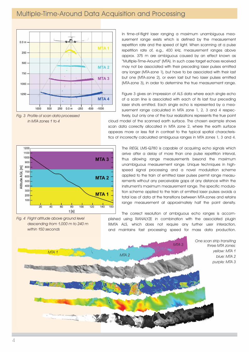
In time-of-flight laser ranging a maximum unambiguous mea-surement range exists which is defined by the measurement repetition rate and the speed of light. When scanning at a pulse repetition rate of, e.g., 400 kHz, measurement ranges above approx. 375 m are ambiguous caused by an effect known as “Multiple-Time-Around” (MTA). In such case target echoes received may not be associated with their preceding laser pulses emitted any longer (MTA-zone 1), but have to be associated with their last but one (MTA-zone 2), or even last but two laser pulses emitted (MTA-zone 3), in order to determine the true measurement range.
Figure 3 gives an impression of ALS data where each single echo of a scan line is associated with each of its last four preceding laser shots emitted. Each single echo is represented by a mea-surement range calculated in MTA zone 1, 2, 3 and 4 respec-tively, but only one of the four realizations represents the true point
cloud model of the scanned earth surface. The chosen example shows scan data correctly allocated in MTA zone 2, where the earth surface appears more or less flat in contrast to the typical spatial characteris-tics of incorrectly calculated ambiguous ranges in MTA zones 1, 3 and 4.
The RIEGL LMS-Q780 is capable of acquiring echo signals which arrive after a delay of more than one pulse repetition interval, thus allowing range measurements beyond the maximum unambiguous measurement range. Unique techniques in high-speed signal processing and a novel modulation scheme applied to the train of emitted laser pulses permit range measu-rements without any perceivable gaps at any distance within the instrument‘s maximum measurement range. The specific modula-tion scheme applied to the train of emitted laser pulses avoids a total loss of data at the transitions between MTA-zones and retains range measurement at approximately half the point density.
The correct resolution of ambiguous echo ranges is accom-plished using RiANALYZE in combination with the associated plugin RiMTA ALS, which does not require any further user interaction,and maintains fast processing speed for mass data production.
Fig. 3 Profile of scan data processed in MTA zones 1 to 4
Fig. 4 Flight altitude above ground level descending from 1,000 m to 240 m within 150 seconds
One scan strip transiting three MTA zones:
yellow: MTA 1blue: MTA 2
purple: MTA 3
MTA 1MTA 2
MTA 3
Multiple-Time-Around Data Acquisition and Processing
4

Poi
nt D
ensi
ty [p
ts/m
2 ]
Speed [kn]
50 7060 80 90 100 110 120 130 140
0.2
0.4
0.6
0.8
1
1.2
1.4
1.6
1.8
5000 ft
6100 ft
7400 ft9000 ft
11000 ft
5000 ft (1520 m)6100 ft (1860 m)7400 ft (2260 m)9000 ft (2740 m)11000 ft (3350 m)
Flight Altitude AGL
1760 m2150 m2600 m3170 m3870 m
Swath Width
Swath Width
Flig
htAl
titud
e AG
L
60°
FOV
Spa
tial S
ampl
ing
Freq
uenc
y [p
ts/m
]
0.3
0.4
1000800
[km
²/h]
600
400
500
300
250
200
180
160
140
120
110
0.5
0.6
0.7
0.8
0.9
Poi
nt D
ensi
ty [p
ts/m
2 ]
Speed [kn]
50 7060 80 90 100 110 120 130 140
0.5
1
1.5
2
3
3.5
2.5
4
4.5
3500 ft
4500 ft
5700 ft
7300 ft
9400 ft
3500 ft (1070 m)4500 ft (1370 m)5700 ft (1740 m)7300 ft (2230 m)9400 ft (2870 m)
Flight Altitude AGL
1230 m1580 m2010 m2570 m3310 m
Swath Width
Swath Width
Flig
ht
Altit
ude
AGL
60°
FOV
Spa
tial S
ampl
ing
Freq
uenc
y [p
ts/m
]
0.6
0.7
0.5
0.9
1.3
1.4
800
600500400
250
200180
160
140
120
90
[km
²/h]
300
100
0.8
1
1.1
1.2
Poi
nt D
ensi
ty [p
ts/m
2 ]
Speed [kn]
50 7060 80 90 100 110 120 130 140
1
2
3
4
5
6
7
8
9
3200 ft
4000 ft
5100 ft
6400 ft8000 ft
3200 ft (980 m)4000 ft (1220 m)5100 ft (1550 m)6400 ft (1950 m)8000 ft (2440 m)
Flight Altitude AGL
1130 m1410 m1790 m2250 m2820 m
Swath width
Swath Width
Flig
htAl
titud
e AG
L
60°
FOV
Spa
tial S
ampl
ing
Freq
uenc
y [p
ts/m
]
0.7
0.9
0.8
1
1.2
1.4
1.6
1.8
2
500
300
200
100
80
70
150
[km
²/h]
120
PRR = 100 kHz, laser power level 100%
400
800
1200
1600
2000
2400
2800
3200
3600
4000
4400
4800
[m] [ft]
Ope
ratin
g Fl
ight
Alti
tude
AG
L
1000
2000
3000
4000
5000
6000
7000
8000
9000
10000
11000
12000
14000
13000
15000
16000
17000
00
500
1000
1500
2000
2500
3000
3500
4000
4500
5000
5500
6000
6500
7000
Max
. Mea
sure
men
t Ran
ge [m
]
0 5 10 15 20 25 30 35 40 45 50 55 60 65 70 75 80
wet
ice
dry
snow
coni
ferio
us tr
ees
dry
asph
alt
deci
duou
s tre
es
terr
a co
tta
cliff
s, s
and,
mas
onry
whi
te p
last
er w
ork,
lim
esto
ne
@ visibility 40 km@ visibility 23 km@ visibility 15 km
MTA 1
MTA 2
MTA 3
MTA 4
ENOHD
5200
5600
PRR = 200 kHz, laser power level 100%
wet
ice
dry
snow
coni
ferio
us tr
ees
dry
asph
alt
deci
duou
s tre
es
terr
a co
tta
cliff
s, s
and,
mas
onry
whi
te p
last
er w
ork,
lim
esto
ne
400
800
1200
1600
2000
2400
2800
3200
3600
4000
4400
4800
[m] [ft]
Ope
ratin
g Fl
ight
Alti
tude
AG
L
1000
2000
3000
4000
5000
6000
7000
8000
9000
10000
11000
12000
14000
13000
15000
16000
17000
0
5200
5600
0
500
1000
1500
2000
2500
3000
3500
4000
4500
5000
5500
6000
6500
7000
Max
. Mea
sure
men
t Ran
ge [m
]
0 5 10 15 20 25 30 35 40 45 50 55 60 65 70 75 80
@ visibility 40 km@ visibility 23 km@ visibility 15 km
MTA 1
MTA 2
MTA 3
MTA 4
MTA 5
MTA 6
MTA 7
MTA 8
ENOHD
PRR = 300 kHz, laser power level 100%
0
500
1000
1500
2000
2500
3000
3500
4000
4500
5000
5500
6000
6500
7000
0 5 10 15 20 25 30 35 40 45 50 55 60 65 70 75 80
wet
ice
dry
snow
coni
ferio
us tr
ees
dry
asph
alt
deci
duou
s tre
es
terr
a co
tta
cliff
s, s
and,
mas
onry
whi
te p
last
er w
ork,
lim
esto
ne
Max
. Mea
sure
men
t Ran
ge [m
]
MTA 1
MTA 2
MTA 3
MTA 4
MTA 5
MTA 6
MTA 7
MTA 8
400
800
1200
1600
2000
2400
2800
3200
3600
4000
4400
4800
5200
5600
[m] [ft]
Ope
ratin
g Fl
ight
Alti
tude
AG
L
1000
2000
3000
4000
5000
6000
7000
8000
9000
10000
11000
12000
14000
13000
15000
16000
17000
0
@ visibility 40 km@ visibility 23 km@ visibility 15 km
ENOHD
Example: LMS-Q780 at 100,000 pulses/sec, laser power level 100% Results: Point Density ~ 0.6 pts/m² Spatial Sampling Frequency ~ 0.53 pts/mCovered Area per Time ~ 320 km²/h
Altitude = 6100ft AGL, Speed = 100 kn
Example: LMS-Q780 at 200,000 pulses/sec, laser power level 100% Results: Point Density ~ 1.6 pts/m² Spatial Sampling Frequency ~ 0.87 pts/mCovered Area per Time ~ 230 km²/h
Altitude = 5700ft AGL, Speed = 80 kn
Example: LMS-Q780 at 300,000 pulses/sec, laser power level 100% Results: Point Density ~ 4 pts/m² Spatial Sampling Frequency ~ 1.35 pts/mCovered Area per Time ~ 140 km²/h
Altitude = 4000ft AGL, Speed = 70 kn
The following conditions are assumed for the Operating Flight Altitude AGL• ambiguity resolved by multiple-time-around (MTA) processing & flight planning
Assumptions for calculation of the Covered Area per Time• 20% overlap of neighboring flight strips. This overlap covers a roll angle of ±5° or a reduction of flight altitude AGL of 20%.• target size ≥ laser footprint
• scan angle 60°• average ambient brightness• roll angle ±5°
Definition of the Spatial Sampling Frequency• The Spatial Sampling Frequency is the reciprocal of the 95th percentile of the distribution function of the maximum distances between neighboring scan points. When considering any individual scan point, the probability to find its most distant neighbor within the reciprocal of the Spatial Sampling Frequency is 95%.
5
Measurement Range & Point Density RIEGL LMS-Q780
Poin
t Den
sity
[pts
/m2 ]
Speed [kn]
5
10
15
20
25
030 40 50 60 70 80 90 100 110 120
1900 ft
2500 ft3300 ft
4300 ft5600 ft
1900 ft (580 m)2500 ft (760 m)3300 ft (1010 m)4300 ft (1310 m)5600 ft (1710 m)
Flight Altitude AGL
670 m 880 m1160 m1510 m1970 m
Swath Width
Swath Width
Flig
htAl
titud
e AG
L
60°
FOV
Spat
ial S
ampl
ing
Freq
uenc
y [p
ts/m
]
1
500
[km
²/h]
300
200150
100
80
60
70
50
45
40
35
31
1.5
2
2.5
3
3.4
Poin
t Den
sity
[pts
/m2 ]
Spat
ial S
ampl
ing
Freq
uenc
y [p
ts/m
]
Speed [kn]
2
4
6
8
10
12
14
16
18
20
0.8
1.21
1.4
1.6
1.8
2
2.2
2.4
2.6
2.8
3
500
300
200
120
100
80
70
60
55
50
150
030 40 50 60 70 80 90 100 110 120
2700 ft
3500 ft
4400 ft5600 ft
7200 ft
2700 ft (820 m)3500 ft (1070 m)4400 ft (1340 m)5600 ft (1710 m)7200 ft (2190 m)
Flight Altitude AGL
950 m1230 m1550 m1970 m2530 m
Swath Width
Swath Width
Flig
htAl
titud
e AG
L
60°
FOV
[km
²/h]
45
40
PRR = 400 kHz, laser power level 50%
wet
ice
dry
snow
coni
ferio
us tr
ees
dry
asph
alt
deci
duou
s tre
es
terr
a co
tta
cliff
s, s
and,
mas
onry
whi
te p
last
er w
ork,
lim
esto
ne
400
1000
2000
2600
3200
[m] [ft]
Ope
ratin
g Fl
ight
Alti
tude
AG
L
1000
2000
6000
10000
00
400
800
1200
1600
2000
2400
2800
3200
3600
4000
4400
4800
Max
. Mea
sure
men
t Ran
ge [m
]
0 5 10 15 20 25 30 35 40 45 50 55 60 65 70 75 80
@ visibility 40 km@ visibility 23 km@ visibility 15 km
MTA 1
MTA 2
MTA 3
MTA 4
MTA 5
MTA 6
MTA 7
MTA 8
ENOHD
PRR = 400 kHz, laser power level 100% M
ax. M
easu
rem
ent R
ange
[m]
0
500
1000
1500
2000
2500
3000
3500
4000
4500
5000
5500
6000
0 5 10 15 20 25 30 35 40 45 50 55 60 65 70 75 80
wet
ice
dry
snow
coni
ferio
us tr
ees
dry
asph
alt
deci
duou
s tre
es
terr
a co
tta
cliff
s, s
and,
mas
onry
whi
te p
last
er w
ork,
lim
esto
ne
MTA 1
MTA 2
MTA 3
MTA 4
MTA 5
MTA 6
MTA 7
MTA 8
@ visibility 40 km@ visibility 23 km@ visibility 15 km
400
800
1200
1600
2000
2400
2800
3200
3600
4000
4400
4800
[m] [ft]
Ope
ratin
g Fl
ight
Alti
tude
AG
L
1000
2000
3000
4000
5000
6000
7000
8000
9000
10000
11000
12000
14000
13000
15000
0
ENOHD
0
500
1000
1500
2000
2500
3000
0 5 10 15 20 25 30 35 40 45 50 55 60 65 70 75 80
wet
ice
dry
snow
coni
ferio
us tr
ees
dry
asph
alt
deci
duou
s tre
es
terr
a co
tta
cliff
s, s
and,
mas
onry
whi
te p
last
er w
ork,
lim
esto
ne
PRR = 400 kHz, laser power level 25%
Max
. Mea
sure
men
t Ran
ge [m
]
MTA 1
MTA 2
MTA 3
MTA 4
400
800
1200
1600
2000
2400
[m] [ft]
Ope
ratin
g Fl
ight
Alti
tude
AG
L
1000
2000
3000
4000
6000
8000
0
@ visibility 40 km@ visibility 23 km@ visibility 15 km
MTA 5
MTA 6
MTA 7
ENOHD
Poin
t Den
sity
[pts
/m2 ]
Speed [kn]
5
10
15
20
25
30
35
40
030 40 50 60 70 80 90 100 110 120
1900 ft2300 ft
2800 ft3300 ft4000 ft
1900 ft (580 m)2300 ft (700 m)2800 ft (850 m)3300 ft (1010 m)4000 ft (1220 m)
Flight Altitude AGL
670 m810 m990 m1160 m1410 m
Swath Width
Swath Width
Flig
htAl
titud
e AG
L
60°
FOV
Spat
ial S
ampl
ing
Freq
uenc
y [p
ts/m
]
1
[km
²/h]
300200150
100
80
60
50
40
35
30
25
22
20
1.5
2
2.5
3
3.5
4
4.3
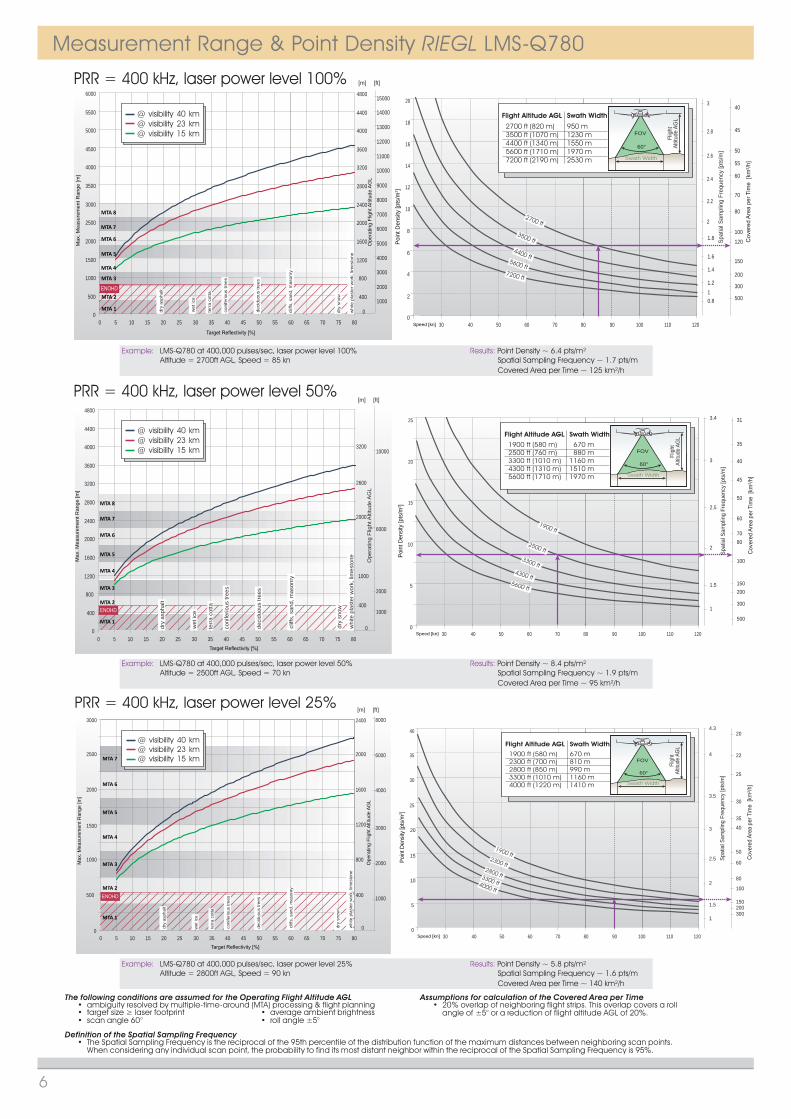
Example: LMS-Q780 at 400,000 pulses/sec, laser power level 50% Results: Point Density ~ 8.4 pts/m² Spatial Sampling Frequency ~ 1.9 pts/mCovered Area per Time ~ 95 km²/h
Altitude = 2500ft AGL, Speed = 70 kn
Example: LMS-Q780 at 400,000 pulses/sec, laser power level 100% Results: Point Density ~ 6.4 pts/m² Spatial Sampling Frequency ~ 1.7 pts/mCovered Area per Time ~ 125 km²/h
Altitude = 2700ft AGL, Speed = 85 kn
Example: LMS-Q780 at 400,000 pulses/sec, laser power level 25% Results: Point Density ~ 5.8 pts/m² Spatial Sampling Frequency ~ 1.6 pts/mCovered Area per Time ~ 140 km²/h
Altitude = 2800ft AGL, Speed = 90 kn
The following conditions are assumed for the Operating Flight Altitude AGL• ambiguity resolved by multiple-time-around (MTA) processing & flight planning
Assumptions for calculation of the Covered Area per Time• 20% overlap of neighboring flight strips. This overlap covers a roll angle of ±5° or a reduction of flight altitude AGL of 20%.• target size ≥ laser footprint
• scan angle 60°• average ambient brightness• roll angle ±5°
Definition of the Spatial Sampling Frequency• The Spatial Sampling Frequency is the reciprocal of the 95th percentile of the distribution function of the maximum distances between neighboring scan points. When considering any individual scan point, the probability to find its most distant neighbor within the reciprocal of the Spatial Sampling Frequency is 95%.
Measurement Range & Point Density RIEGL LMS-Q780
6

Poin
t Den
sity
[pts
/m2 ]
Speed [kn]
5
10
15
20
25
30
35
40
45
50
030 40 50 60 70 80 90 100 110 120
1200 ft1500 ft
1900 ft2400 ft
3000 ft
1200 ft (370 m)1500 ft (460 m)1900 ft (580 m)2400 ft (730 m)3000 ft (910 m)
Flight Altitude AGL
420 m530 m670 m840 m1060 m
Swath Width
Swath Width
Flig
htAl
titud
e AG
L
60°
FOV
Spat
ial S
ampl
ing
Freq
uenc
y [p
ts/m
]
1
[km
²/h]
200150
10080
60
50
40
30
35
25
20
18
16
22
1.5
2
2.5
3
3.5
4
4.5
4.8
PRR = 400 kHz, laser power level 12%
Max
. Mea
sure
men
t Ran
ge [m
]
0
600
1200
1800
2400
0 5 10 15 20 25 30 35 40 45 50 55 60 65 70 75 80
wet
ice
dry
snow
coni
ferio
us tr
ees
dry
asph
alt
deci
duou
s tre
es
terr
a co
tta
cliff
s, s
and,
mas
onry
whi
te p
last
er w
ork,
lim
esto
ne
MTA 1
MTA 2
MTA 3
MTA 4
MTA 6@ visibility 40 km@ visibility 23 km@ visibility 15 km
MTA 5
ENOHD
400
800
1200
1600
[m] [ft]
Ope
ratin
g Fl
ight
Alti
tude
AG
L
1000
2000
3000
4000
5000
0
PRR = 400 kHz, laser power level 6%
Max
. Mea
sure
men
t Ran
ge [m
]
0
600
300
900
1200
1500
1800
0 5 10 15 20 25 30 35 40 45 50 55 60 65 70 75 80
wet
ice
dry
snow
coni
ferio
us tr
ees
dry
asph
alt
deci
duou
s tre
es
terr
a co
tta
cliff
s, s
and,
mas
onry
whi
te p
last
er w
ork,
lim
esto
ne
MTA 1
MTA 2
MTA 3
MTA 4
@ visibility 40 km@ visibility 23 km@ visibility 15 km
400
800
1200
[m] [ft]
Ope
ratin
g Fl
ight
Alti
tude
AG
L
1000
2000
3000
4000
0
ENOHD
Poin
t Den
sity
[pts
/m2 ]
Speed [kn]
10
20
30
40
50
60
70
80
030 40 50 60 70 80 90 100 110 120
850 ft1100 ft
1400 ft1800 ft2200 ft
850 ft (260 m)1100 ft (340 m)1400 ft (430 m)1800 ft (550 m)2200 ft (670 m)
Flight Altitude AGL
300 m390 m490 m630 m770 m
Swath Width
Swath Width
Flig
htAl
titud
e AG
L
60°
FOV
Spat
ial S
ampl
ing
Freq
uenc
y [p
ts/m
]
1.5 150
[km
²/h]
100806050
40
30
25
20
18
16
14
12
11
10
2
2.5
3
3.5
4
4.5
5
6
5.5
Example: LMS-Q780 at 400,000 pulses/sec, laser power level 12% Results: Point Density ~ 15.3 pts/m² Spatial Sampling Frequency ~ 2.6 pts/mCovered Area per Time ~ 50 km²/h
Altitude = 1200ft AGL, Speed = 80 kn
Example: LMS-Q780 at 400,000 pulses/sec, laser power level 6% Results: Point Density ~ 24.7 pts/m² Spatial Sampling Frequency ~ 3.4 pts/mCovered Area per Time ~ 30 km²/h
Altitude = 850ft AGL, Speed = 70 kn
The following conditions are assumed for the Operating Flight Altitude AGL• ambiguity resolved by multiple-time-around (MTA) processing & flight planning
Assumptions for calculation of the Covered Area per Time• 20% overlap of neighboring flight strips. This overlap covers a roll angle of ±5° or a reduction of flight altitude AGL of 20%.• target size ≥ laser footprint
• scan angle 60°• average ambient brightness• roll angle ±5°
Definition of the Spatial Sampling Frequency• The Spatial Sampling Frequency is the reciprocal of the 95th percentile of the distribution function of the maximum distances between neighboring scan points. When considering any individual scan point, the probability to find its most distant neighbor within the reciprocal of the Spatial Sampling Frequency is 95%.
7
Measurement Range & Point Density RIEGL LMS-Q780
Technical Data RIEGL LMS-Q780 (continued)
Data InterfacesConfiguration TCP/IP Ethernet (10/100 MBit), RS232 (19.2 kBd)Monitoring Data Output TCP/IP Ethernet (10/100 MBit)Digitized Data Output High speed serial data link to RIEGL Data RecorderSynchronization Serial RS232 interface, TTL input for 1 pps synchronization pulse, accepts different data formats for GNSS-time information
General Technical DataPower Supply / Current Consumption 18 - 32 V DC / approx. 7 A @ 24 VDC Main Dimensions (L x W x H) / Weight 480 x 212 x 279 mm / approx. 20 kgProtection Class IP54Max. Flight Altitude operating / not operating 18500 ft (5600 m) above Mean Sea Level MSL / 18500 ft (5600 m) above MSL Temperature Range -5°C up to +40°C (operation) / -10°C up to +50°C (storage)
Mounting of IMU-Sensor Steel thread inserts on both sides of the laser scanner, rigidly connected to the inner structure of the scanning mechanism

www.riegl.comInformation contained herein is believed to be accurate and reliable. However, no responsibility is assumed by RIEGL for its use. Technical data are subject to change without notice.
Data Sheet, RIEGL LMS-Q780, 2015-03-24
Dimensional Drawings RIEGL LMS-Q780
RIEGL Laser Measurement Systems GmbHRiedenburgstraße 483580 Horn, AustriaPhone: +43 2982 4211 | Fax: +43 2982 [email protected]
RIEGL USA Inc.Orlando, Florida | [email protected] | www.rieglusa.com
RIEGL Japan Ltd.Tokyo, Japan | [email protected] | www.riegl-japan.co.jp
RIEGL China Ltd.Beijing, China | [email protected] | www.riegl.cn