full text pdf (1.87 mb) - iopscience
TRANSCRIPT
Science and Technology ofAdvanced Materials
Improved fire retardancy of thermoset compositesmodified with carbon nanofibersTo cite this article: Zhongfu Zhao and Jan Gou 2009 Sci. Technol. Adv. Mater. 10 015005
View the article online for updates and enhancements.
You may also likeDynamics of ecosystems and land use inthe Dnieper left-bank forest-steppe for thelast two thousand years: Kurilovka 2 casestudyV E Rodinkova, E V Ponomarenko, E GErshova et al.
-
Charring Rate for Fire Exposed X-LamBernice VY Wong and Kong Fah Tee
-
Development of led-curable intumescentpolymer coatings for fire protection ofbuilding constructionsA Tomakhova, O Zybina, V Suprun et al.
-
Recent citationsA Comprehensive review on thehierarchical performances of eco-friendlyand functionally advanced modified andrecyclable carbon materialsIrfan Shah and Rohana Adnan
-
Lightweight carbon nanotube surfacethermal shielding for carbonfiber/bismaleimide compositesZhe Liu et al
-
Quynh Thuy Nguyen et al-
This content was downloaded from IP address 109.196.2.89 on 16/12/2021 at 06:03

IOP PUBLISHING SCIENCE AND TECHNOLOGY OF ADVANCED MATERIALS
Sci. Technol. Adv. Mater. 10 (2009) 015005 (6pp) doi:10.1088/1468-6996/10/1/015005
Improved fire retardancy of thermosetcomposites modified with carbonnanofibersZhongfu Zhao1 and Jan Gou2
1 State Key Laboratory of Fine Chemicals, Department of Polymer Science and Engineering,School of Chemical Engineering, Dalian University of Technology, 158 Zhongshan Road,Dalian 116012, People’s Republic of China2 Department of Mechanical, Materials and Aerospace Engineering University of Central Florida,FL 32816, USA
E-mail: [email protected]
Received 28 November 2008Accepted for publication 1 February 2009Published 4 March 2009Online at stacks.iop.org/STAM/10/015005
AbstractMultifunctional thermoset composites were made from polyester resin, glass fiber mats andcarbon nanofiber sheets (CNS). Their flaming behavior was investigated with cone calorimeterunder well-controlled combustion conditions. The heat release rate was lowered bypre-planting carbon nanofiber sheets on the sample surface with the total fiber content of only0.38 wt.%. Electron microscopy showed that carbon nanofiber sheet was partly burned andcharred materials were formed on the combusting surface. Both the nanofibers and charredmaterials acted as an excellent insulator and/or mass transport barrier, improving the fireretardancy of the composite. This behavior agrees well with the general mechanism of fireretardancy in various nanoparticle-thermoplastic composites.
Keywords: flame retardance, carbon nanofiber, composites
(Some figures in this article are in colour only in the electronic version)
1. Introduction
In the recent decade, great attention has been paid tonanoparticles for making polymeric nanocompositeswith exceptional properties. These nanoparticles areenvironmentally friendly and will not produce toxic gases.Layered silicates are widely used for an improvement in flameretardancy, but carbon nanotubes (CNTs) have been provedmore efficient [1–9]. It has been found [1–4] that their flameretarding performance can be achieved through the formationof a relatively uniform network of carbon nanotubes, coveringthe entire sample surface without any cracks or gaps. Thenetwork layer re-emits much of the incident radiation backinto the gas phase from its hot surface and thus reduces thetransmitted flux to the underlying polymer layer, slowingdown the polymer pyrolysis rate. To form efficient carbon
nanotube network on the sample surface, enough carbonnanotubes should be compounded with the polymer matrix.However, addition of carbon nanotubes significantly increasesthe viscosity of polymer resin. In addition, it is difficult touniformly disperse CNTs into polymer matrix due tostrong van der Waals force between them. Another kind ofcarbon materials, carbon nanofiber, has been investigatedto enhance thermal property, electrical conductivity andmechanical properties due to its highly extended structuresand cost advantage [10–15]. Both carbon nanotubes andcarbon nanofibers have similar rope-like structures, butcarbon nanofibers have much larger diameters. It has beenpointed out that carbon nanofibers could enhance the fireretardancy of polymers if they are uniformly dispersed inpolymer resins [4]. Just like other nanoparticles, carbonnanofibers form continuous protective barrier/insulator layer
1468-6996/09/015005+06$30.00 1 © 2009 National Institute for Materials Science Printed in the UK
Sci. Technol. Adv. Mater. 10 (2009) 015005 Z Zhao and J Gou
through the accumulation of nanoparticles on the combustingsurfaces [1–4]. Only few flame resistance studies have beenreported using carbon nanofibers [4].
Although nanoparticles have been successfully used toenhance the fire retardancy of polymer nanocomposites, thehost materials are mostly thermoplastic polymers, which havenot been studied much in this regard. Thermoset compositescan be made of various resins at much lower temperature.After being cured, they form cross-linked structures withhigh strength. Thus, these composites, especially when fiberreinforced, have become attractive engineering materials toreplace conventional metals in many important sectors ofindustry such as aircraft, naval constructions, ships, buildingand offshore structures. These materials are susceptibleto combustion and fire damage due to their chemicalstructure. This leads to concerns about their fire retardancyand structural integrity during and after the exposure tofire. In order to increase their market penetration andabide by current stringent aviation and other legislationsto increase safety [16–18], there is an urgent need todevelop an approach to improve the fire retardancy offiber-reinforced composites. When these nanoparticles areblended with thermoset resin prior to fiber impregnation, afew problems occur such as heavy reagglomeration, poorcompatibility, poor processability, leaching, and reducedmechanical properties [19, 20]. In the case of carbonnanofibers, relatively high loading levels will be required dueto their low fire retardation efficiency that would only worsenthe processing issues.
In this article, a novel method is explored to improvethe fire retardancy of fiber-reinforced thermoset composites,in which a freestanding carbon nanofiber sheet is pre-plantedon the sample surface. This method not only reducesaforementioned problems in processing glass fiber/polyestercomposites with nanoparticles but also concentrates carbonnanofiber at the combusting surface; as a result, much lowertotal fiber concentration is sufficient for fire protection (below1 wt.%) [21, 22].
2. Experimental details
2.1. Materials and preparation of samples
Vapor grown carbon nanofibers (Polygraf III PR19) werepurchased from Applied Sciences, Inc. The fibers havediameters of 50–150 nm and lengths of 30–100 µm; theycould be dispersed in aqueous solution with the aid ofsurfactants. Surfactants (Nano Sperse AQ) were ordered fromNanolab Company (USA). Carbon nanofiber sheet was madethrough filtering aqueous solution of the fibers; it had thethickness of 0.23 mm and bulk density of 0.19 g cm−3. Theunsaturated polyester resin (712–6117, Eastman ChemicalCompany) was used as matrix material with the MEKperoxide hardener at a weight ratio of 100 : 1. Glass fiber matshad its surface density of 800 g cm−2 and average thickness of0.85 mm.
The as-received carbon nanofiber powders were groundin a mortar with a small amount of de-ionized water. After
Table 1. Sample composition.
Components fraction (wt.%) Thickness
Samples Glass Resin CNFa CNSb (mm)
GR-CNS 56.7 43 – 0.38 6.9GR-CNF 56.6 43 0.38 – 6.8GR 56.4 43.6 – – 6.9
acarbon nanofiber.bcarbon nanofiber sheet.
Figure 1. Heat release rate curves of GR-CNS, GR-CNF and GR.
grinding, they were transferred into a 500 ml glass beaker,and 400 ml of water was added together with four drops ofsurfactants. Their mixture was subsequently sonicated usinga high intensity sonicator (600-watt Sonicator 3000 fromMisonix Inc) for 20 min at a power of 30–50 watts. After thesolution and probe were cooled down to room temperature,the solution was sonicated for 20 more min under the samecondition. The as-prepared solution was allowed to settleovernight and 300 ml of the suspension was collected.The above process was repeated a few times. The finalmixture was treated with the ultrasonic sonicator for 10 minbefore being filtered with 0.4 µm hydrophilic polycarbonatemembrane with the aid of both vacuum and high-pressure air.
Resin transfer molding process had been used tomanufacture three samples, in which eight plies of glass fibermats were preformed in molds. With the aid of vacuum pump,polyester resin could flow and finally cure inside the channelsof fiber mats and carbon nanofiber sheet. These samples werenamed of GR, GR-CNS and GR-CNF, respectively. Theircomposition is listed in table 1. Only glass fiber mats wereused in sample GR. Carbon nanofiber sheet fraction was only0.38 wt.% of thermoset resin in GR-CNS. To compare theeffect of different addition methods on the fire retardancy,the same loading level of carbon nanofiber was used inGR-CNF. In GR-CNS, one ply of carbon nanofiber sheet wasfirst sealed on the bottom of mold, which became the frontsurface after de-molding. Pure polyester resin was infusedinto GR-CNS and GR. However, to prepare GR-CNF, carbonnanofiber was first dispersed in polyester resin (treated withhigh speed mixer and degassed with vacuum pump) and thentheir mixture was fused into the mold. All samples were curedat room temperature for 24 h and post-cured in the oven for 2 hat 120 ◦C. Samples were cut into 100 × 100 mm2 squares forfire retardancy test.
2
Sci. Technol. Adv. Mater. 10 (2009) 015005 Z Zhao and J Gou
(a)
(b) (c)
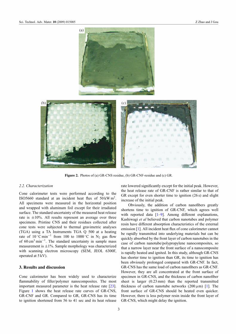
Figure 2. Photos of (a) GR-CNS residue, (b) GR-CNF-residue and (c) GR.
2.2. Characterization
Cone calorimeter tests were performed according to theISO5660 standard at an incident heat flux of 50 kW m2.All specimens were measured in the horizontal positionand wrapped with aluminum foil except for their irradiatedsurface. The standard uncertainty of the measured heat releaserate is ±10%. All results represent an average over threespecimens. Pristine CNS and their residues collected aftercone tests were subjected to thermal gravimetric analyses(TGA) using a TA Instruments TGA Q 500 at a heatingrate of 10 ◦C min−1 from 100 to 1000 ◦C in N2 gas flowof 60 cm3 min−1. The standard uncertainty in sample massmeasurement is ±1%. Sample morphology was characterizedwith scanning electron microscopy (SEM, JEOL 6300F,operated at 5 kV).
3. Results and discussion
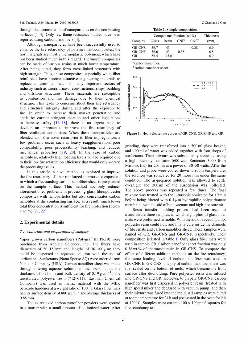
Cone calorimeter has been widely used to characterizeflammability of filler/polymer nanocomposites. The mostimportant measured parameter is the heat release rate [23].Figure 1 shows the heat release rate curves of GR-CNS,GR-CNF and GR. Compared to GR, GR-CNS has its timeto ignition shortened from 56 to 41 sec and its heat release
rate lowered significantly except for the initial peak. However,the heat release rate of GR-CNF is rather similar to that ofGR except for even shorter time to ignition (26 s) and slightincrease of the initial peak.
Obviously, the addition of carbon nanofibers greatlyshortens time to ignition of GR-CNF, which agrees wellwith reported data [1–9]. Among different explanations,Kashiwagi et al believed that carbon nanotubes and polymerresin have different absorption characteristics of the externalemission [1]. All incident heat flux of cone calorimeter cannotbe rapidly transmitted into underlying materials but can bequickly absorbed by the front layer of carbon nanotubes in thecase of carbon nanotube/polypropylene nanocomposites, sothat a narrow layer near the front surface of a nanocompositeis rapidly heated and ignited. In this study, although GR-CNShas shorter time to ignition than GR, its time to ignition hasbeen obviously prolonged compared with GR-CNF. In fact,GR-CNS has the same load of carbon nanofibers as GR-CNF.However, they are all concentrated at the front surface ofspecimen in GR-CNS, and the thickness of carbon nanofibersheet is larger (0.23 mm) than the reported transmittedthickness of carbon nanotube networks (200 µm) [1]. Thefront surface of GR-CNS should be heated even quicker.However, there is less polymer resin inside the front layer ofGR-CNS, which might delay the ignition.
3

Sci. Technol. Adv. Mater. 10 (2009) 015005 Z Zhao and J Gou
Figure 3. SEM images of (a) pristine carbon nanofiber sheet,(b) underlayer residue and (c) upper residue of the burned GR-CNSsample.
For GR-CNF and GR, the heat release rate curves nearlyoverlap except for their ignition stage. Therefore, there is noobvious improvement of fire retardancy through dispersingcarbon nanofibers in the composites. On the contrary,GR-CNS has its heat release rate curve sharply increased atthe early ignition stage and then quickly decreased to thelowest level. GR-CNS has a carbon nanofiber sheet and thusless polymer resin at the front surface. The incident heatflux can be quickly absorbed by the front carbon nanofiber
200 400 600 800 100050
60
70
80
90
100
(a)
(b)
)%( ssol thgie
W
Temperature (oC)
Pristine CNS Underlayer residuesUpper residues
200 400 600 800 1000
0.00
0.05
0.10
0.15t
d/)t.w(d
ATD
Temperature (oC)
Pristine CNS Underlayer residuesUpper residues
Figure 4. (a) TGA and (b) DTA curves of pristine CNS, underlayerresidues and upper residues (pristine CNS: pristine carbon nanofibersheet).
sheet, which can rapidly heat and pyrolyze the surroundingmaterials. As a result, GR-CNS quickly reaches its heatrelease rate peak. After the front layer of GR-CNS hasburned, the heat release rate drops down quickly. Comparedwith GR-CNF and GR, GR-CNS has good fire retardantperformance due to its lower heat release rate before 400 s.After 400 s, GR-CNS still has much polymer left unburned,which leads to higher heat release rate as compared toGR-CNF and GR.
Sample residues were collected at the end of the conecalorimeter tests (figure 2). GR-CNF and GR have less residueleft at the front surface, and most glass fiber mats are exposedwithout being destroyed or contaminated. But GR-CNS hasa unique residue, consisting of two layers. The upper one isblack and has no crack or gaps. It is a soft material witha thickness of 0.64 mm, much larger than pristine carbonnanofiber sheet thickness (0.23 mm). The underlayer residueis much thinner (< 0.1 mm), but it is brittle.
The residual materials of GR-CNS and pristine carbonnanofiber sheet were characterized with SEM (figure 3).The pristine carbon nanofiber sheet mainly consists of
4

Sci. Technol. Adv. Mater. 10 (2009) 015005 Z Zhao and J Gou
0 200 400 600 800 1000
0
20
40
60
80
100
0 200 400 600 800 1000
0.0
0.2
0.4
0.6
0.8
1.0
DT
A d
(wt.
)/d
t)
Polyester resin
Wt.
%
Temperature (°C)
Figure 5. TGA and DTA analyses of polyester resin.
well-dispersed long individual carbon nanofibers forming anetwork (figure 3(a)). In addition, there are some ellipticalparticles originating from the metal catalysts used in thenanofiber synthesis. The underlying residue is a partiallyburned carbon nanofiber sheet with rough surfaces. Comparedto pristine carbon nanofiber, the thinner carbon nanofibers areburned out and thicker ones have survived the combustion(figure 3(b)); those thicker nanofibers have shortened. Clearly,the pristine carbon nanofiber sheet was partially damagedduring the fire test. The upper residue consists of a uniformnetwork of floccules with much smaller pore size thanpristine and underlayer residues (figure 3(c)). Although it isunclear how the upper residue is formed, the existence ofcarbon nanofiber sheet should play an important role in theirformation during combustion.
The residues of GR-CNS and pristine carbon nanofibersheet were characterized by TGA (figure 4). Their thermalstability and weight loss should give important informationto their flame retardant behavior. The weight loss ofpristine carbon nanofiber sheet gradually decreases withthe temperature and there is only ∼3% of weight loss at500 ◦C—a characteristic combustion temperature. However,the underlayer residue shows much higher weight loss∼8% at 500 ◦C. Therefore, the thermal stability of the carbonnanofiber sheet is reduced by combustion. Upper residueshows medium thermal stability with ∼6% of weight loss at500 ◦C. In the temperature range 100–800 ◦C, pristine carbonnanofiber sheet has two weak DTA peaks. Underlayer residueshows similar DTA curves except for the much strongerDTA peaks at temperatures 120–350 ◦C and 400–800 ◦C.Similarly, upper residues exhibit similar two DTA peaksdifferent from those of pristine and underlayer residues. Thesepeaks shift to the higher temperatures of 150–400 ◦C and500–800 ◦C, respectively. This observation can be interpretedas the upper residue has components of carbon nanofiber andsomething else. As mentioned above, the composites consistof glass fiber, carbon nanofiber and polyester. Glass fiberhas good thermal stability at the temperature of the conetests. Therefore, the formation of upper residues should have
Figure 6. Proposed mechanism of fire retardance of GR-CNS(CNF: carbon nanofiber).
relationship with carbon nanofiber and polyester. However,polyester resin completely decomposes at ∼450 ◦C with abroad DTA peak at 280–450 ◦C (figure 5) and cannot be theuncertain component of the upper residue. We suggest thatthe upper residues consist of heavily burned carbon nanofiberand some charred materials from polyester resin. The burnedcarbon nanofiber is covered with those charred materials.They could survive the temperature of combusting surface(∼400–500 ◦C) [2] and protect the underlying polymer resin.
Based on the above results, the fire retardance mechanismis proposed in figure 6. Thermoset composites havecross-linking structures, in which nanoparticles cannot moveuntil the cross-linking structures are destroyed. Therefore,fire retardancy of thermoset composites cannot be achievedthrough the accumulation of nanoparticles on the combustingsurfaces. The formation of carbon nanofiber networks insidethe cross-linking structures plays a crucial role in enhancingthe fire retardancy of thermoset composites. When carbonnanofibers are uniformly dispersed in thermoset resin, thenanofiber concentration should be high enough so that thecarbon nanofiber network is formed. GR-CNF in figure 6has no network of carbon nanofibers due to their lowconcentration (0.38 wt.%). Consequently, GR-CNF has nofire retardancy relative to pure thermoset composites. Ifthe same loading level is used through pre-planting carbonnanofiber sheet on the surfaces of thermoset composites,such as GR-CNS, the network structures of carbon nanofibersheet could work as an insulator/barrier on the combustingsurfaces of thermoset composites. Furthermore, the carbonnanofiber sheet promotes the formation of charred materials,which works together with carbon nanofiber sheet on thecombusting surfaces to enhance the fire retardancy ofthermoset composites.
4. Conclusions
Fire retardancy of thermoset composites was improvedthrough pre-planting carbon nanofiber sheet on their surfaces.This result agrees well with the main mechanism of fireretardancy in nanoparticle-filled thermoplastic nanocompo-sites. Carbon nanofiber sheet promotes the formation ofcharred materials. Carbon nanofiber sheet and charred
5
Sci. Technol. Adv. Mater. 10 (2009) 015005 Z Zhao and J Gou
materials can work together to re-emit the incident radiationback into the gas phase or/and to slow down the escape of thevolatile products generated during combustion. This methodenhanced the fire retardation efficiency of the compositecontaining only 0.38 wt.% of carbon nanofibers, which is farlower than 4 wt% threshold reported previously [4].
References
[1] Kashiwagi T, Grulke E, Hilding J, Harris R H Jr, Awad W andDouglas J F 2002 Macromol. Rapid Commun. 23 761
[2] Kashiwagi T, Grulke E, Hilding J, Groth K, Harris R H Jr andButler K 2004 Polymer 45 4227
[3] Kashiwagi T, Du F M, Winey K I, Harris R H Jr, Shields J Rand Douglas J F 2005 Polymer 46 471
[4] Kashiwagi T, Du F M, Douglas J F, Winey K I, Harris R H Jrand Shields J R 2005 Nature Mater. 4 928
[5] Gilman J W 1999 Appl. Clay Sci. 15 31[6] Zanetti M and Camino G 2001 Polym. Degrad. Stab.
74 413[7] Tang T, Chen X, Chen H, Meng M, Jiang Z and Bi W 2005
Chem. Mater. 17 2799[8] Kashiwagi T, Harris R H Jr, Zhang X, Briber R M, Cipriano
B H and Raghavan S R 2004 Polymer 45 881
[9] Ribeiro S P S, Estevao L R M and Nascimento R S V 2008 Sci.Technol. Adv. Mater. 9 024408
[10] Xu Y J, Higgins B and Brittain W J 2005 Polymer 46 799[11] Xie H, Gu H, Fu M and Zhang X 2006 Int. J. Thermophys.
27 244[12] Kumar S, Rath T, Mahaling R N, Reddy C S, Das C K, Pandey
K N, Srivastava R B and Yadaw S B 2007 Mater. Sci. Eng.B 141 61
[13] Jimenez G A and Jana S C 2007 Carbon 45 2079[14] Klosterman D, Williams M and Heitkamp C 2007 SAMPE J.
43 7[15] Kumar S, Rath T, Mahaling R N and Das C K 2007
Composites: Part A 38 1304[16] Kandola B K, Akonda M H and Horrocks A R 2005 Polym.
Degrad. Stab. 88 123[17] Mortaigne B, Bourbigot S, Le Bras M, Cordellier G, Baudry A
and Dufay J 1999 Polym. Degrad. Stab. 64 443[18] Le Lay F and Gutierrez J 1999 Polym. Degrad. Stab. 64 397[19] Malte H G, Sumfleth J, Gojny F H, Quaresimin M, Fiedler B
and Schulte K 2006 Eng. Fract. Mech. 73 2346[20] Gojny F H, Wichmann M H G, Fiedler B, Bauhofer W and
Schulte K 2005 Composites A 36 1525[21] Gou J H, Liang Y and Wang B 2004 Int. J. Nanosci. 3 293[22] Gou J, O’Braint S, Gu H and Song G 2006 J. Nanomater.
32803 1[23] Babrauskas V and Peacock R D 1992 Fire Saf. J. 18 255
6