full seeding kit - mcelettronica.it · full seeding kit instructions for use no. 1405-fs oem-it...
TRANSCRIPT

–
FULL SEEDING KIT
INSTRUCTIONS FOR USE
NO. 1405-FS
OEM-IT
REV. 0 EN
O.E.M. VERSION (MANUFACTURERS)
MONITORING SYSTEM
FOR PRECISION SEED DRILLS

Instructions for use
FULL SEEDING KIT
2
This product meets the EMC standards as determined in the
2004/108/EC directive and subsequent amendments and reference to the applied EN ISO 14982 standard
Manufacturer : MC elettronica S.r.l.
Address : Via E. Fermi, 450/486
Fiesso Umbertiano (ROVIGO) - ITALY
Tel. +39 0425 754713 Fax +39 0425 741130
E-mail: [email protected]
Internet: www.mcelettronica.it
Manual code : 1405FS-OEM-IT
Issued : February 2017
Edition : February 2017
MC elettronica S.r.l. is not obliged to give notice of any further modifications of the product.
The information given in this manual does not allow unauthorised personnel to tamper with the product in any way.
The warranty on the equipment will no longer be valid if tampering should be detected.
© Copyright MC elettronica 2017
Front panel 1 Reading instrument with automatic scale change
2 LED for millesimal scale
3 LED for centesimal scale
4 Mechanical adjustment of monitor
5 Functions selector switch
6 Cycle LEDs
7 Delay end LED
8 Adjustment buttons

Instructions for use
FULL SEEDING KIT
3
Contents
1. Rules and general warnings ................................................................................ 5 1.1 Introduction ....................................................................................................... 5 1.2 Terms of the warranty ....................................................................................... 6 1.3 Service .............................................................................................................. 6
2. General description .............................................................................................. 7 3. System installation ............................................................................................. 10
3.1 Electrical connections ..................................................................................... 12 3.2 Virtual Terminal assembly ............................................................................... 14 3.3 Sensor installation ........................................................................................... 15
3.3.1 Speed sensor installation ......................................................................... 15 3.3.2 Magnetic sensor installation ..................................................................... 16 3.3.3 Seed sensor and the wiring harness installation ...................................... 17 3.3.4 Flowmeter sensor installation ................................................................... 19 3.3.5 Radar sensor and GPS installation .......................................................... 20
3.4 Operation ........................................................................................................ 21 3.4.1 Seed sensor recognition .......................................................................... 21 3.4.2 Keyboard operation .................................................................................. 24 3.4.3 Main Parameter Screen ........................................................................... 28 3.4.4 Programming screens .............................................................................. 29
3.5 Graphic interface description .......................................................................... 30 3.5.1 Seed drill work screen .............................................................................. 30
3.6 Automatic exclusion of inspection on the rows ................................................ 38 4. Programming ....................................................................................................... 40
4.1 Virtual Terminal programming ......................................................................... 41 4.1.1 Dimmer settings ....................................................................................... 42 4.1.2 Date and Time setting .............................................................................. 43
4.2 Seeding ECU programming ............................................................................ 44 4.2.1 Main parameters ...................................................................................... 44 4.2.2 Menu ........................................................................................................ 45
5. Software updates ................................................................................................ 63 5.1 Virtual Terminal software update .................................................................... 64
5.1.1 ECU software update ............................................................................... 66 6. Programmable parameters................................................................................. 67 7. Alarms .................................................................................................................. 70 8. Maintenance ........................................................................................................ 71
8.1 Routine maintenance ...................................................................................... 71 8.1.1 How to protect the main connector .......................................................... 71
9. Troubleshooting .................................................................................................. 72 10. Technical data ................................................................................................... 73
10.1 7” Virtual Terminal ......................................................................................... 73

Instructions for use
FULL SEEDING KIT
4
10.2 ECU-SEM ..................................................................................................... 73 10.3 Accessories ................................................................................................... 74
10.3.1 Pipe seed sensors.................................................................................. 74 10.3.2 Bracket seed sensors............................................................................. 74 10.3.1 Proximity inductive sensor ..................................................................... 74 10.3.2 Magnetic sensor ..................................................................................... 75

Instructions for use
FULL SEEDING KIT
5
1. Rules and general warnings
1.1 Introduction
This instruction manual provides all specific information needed to know and correctly use the equipment.
After buying the Monitor, read the manual carefully and refer to it any time you have doubts on how to use the equipment or when you have to carry out maintenance operations.
Keep the manual on the machine. If this is not possible, keep it ready at hand.
ALL RIGHTS RESERVED. THIS MANUAL IS INTENDED FOR CUSTOMERS ONLY. ANY
OTHER USE IS FORBIDDEN.

Instructions for use
FULL SEEDING KIT
6
1.2 Terms of the warranty
SUBJECT OF THE WARRANTY: the warranty is applied to the product and to those parts which are marked with the serial number or any other identification number used by MC elettronica;
DURATION OF THE WARRANTY: MC elettronica guarantees the Full Seeding KIT and its accessories for a period of 1 year from the date of manufacture
(printed on the identification label on the back of the Monitor).
The warranty covers the product and any repairs carried out within the agreed terms.
This warranty does not apply in the event of:
accidental damage;
improper use;
changes which have not been agreed upon, improper installation (or set-up);
damage caused when a equipment not manufactured by MC elettronica,
which is mechanically or electrically connected to our instruments, breaks or does not function properly;
force majeure events (lightning, floods, fire or other causes which do not depend on MC elettronica).
Repairs under warranty, which must be carried out in the laboratories of our authorised centres, are entirely free of charge provided the equipment is directly transported to said laboratories or sent carriage free. Transport costs and ensuing risks are entirely borne by the Customer.
The above-mentioned warranty is valid unless otherwise agreed between MC elettronica and the Customer.
!
Warning
MC elettronica declines any liability for damages or direct or indirect costs caused by improper use or inability of the Customer to use the equipment separately and/or together with other equipment.
1.3 Service
Service is available in all countries where the equipment is officially supplied by MC elettronica (during and after the warranty period).
Any kind of operation to be performed on the Full Seeding KIT must be carried out in accordance with the instructions provided in this manual or as agreed with MC elettronica.
If not, the relative terms of the warranty might become null and void.

Instructions for use
FULL SEEDING KIT
7
2. General description
The Full seeding kit is a system designed for application on pneumatic precision seed drills, the main functions of which are:
Check of the sowing distance and seed life for each row (max 48 rows); the data for sowing distance and seed life is represented in numeric format (value) and in analogue format (histograms)
Check of the presence of granular fertiliser (check ON/OFF) for each row (max 48 rows)
Audible and visual alarms in the event of sowing that does not comply or the absence of fertiliser
Calculation of the processed area; a total counter and up to 9 partial counters are available.
Linear distance travelled.
Yield (ha/h)
There are also other functions available such as:
Display of RPM fan and visual and audible alarms (RPMmax and RPMmin programmable)
Display of the quantity of localised herbicide and audible and visual alarms (Δl/ha programmable)
Display for displaying analogue video signal (PAL) of a camera (not supplied);
furthermore, the Full Seeding kit is equipped with other inlets that can be used for other applications and another analogue video input (PAL) that can be configured on request: contact MC Elettronica's Technical Department for further details.
The connection architecture of the Full seeding kit is of modular and self-configuring type; up to a maximum of 48 seed sensors + 48 fertiliser seed sensors (a total of 96 inputs), to which 16 additional inputs for other sensors are added (feed-rate, area counter override, localised herbicide flowmeter, etc.).
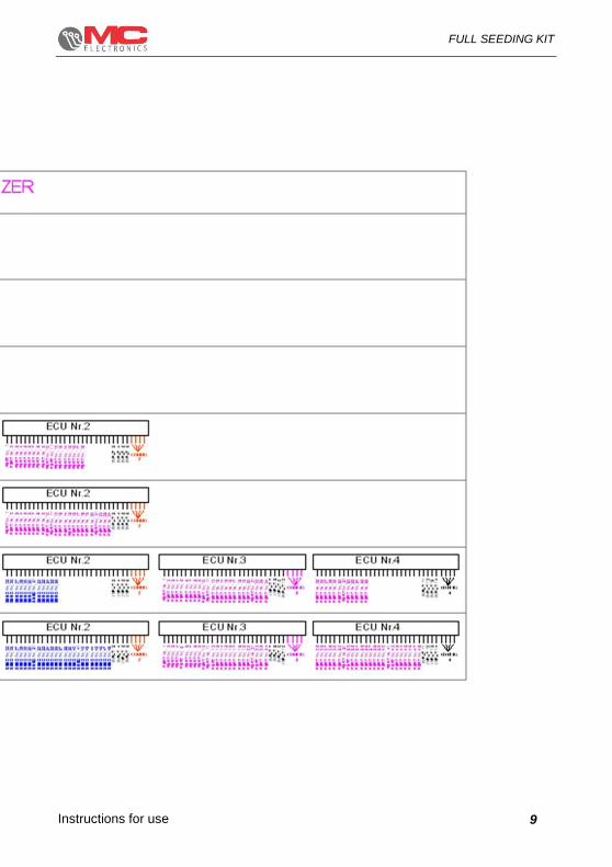
Each seeding ECU can handle 24 seed sensor inputs (24 seed or 24 fertiliser or 12 seed + 12 fertiliser); a connector configuration has been provided for to connect its relative accessory. Each seeding ECU can be connected indifferently to each wiring harness and the KIT will automatically recognise the configuration. The diagram on the next page shows the main configurations (for different configurations, contact Elettronica's Technical Department).

Instructions for use
FULL SEEDING KIT
8
Instructions for use
FULL SEEDING KIT
9

Instructions for use
FULL SEEDING KIT
10
3. System installation
Figure 1 7-inch Virtual Terminal dimensions

Instructions for use
FULL SEEDING KIT
11
Figure 2 Seeding ECU dimensions code 10CEN-ECUSEM
Figure 3 ECU Gateway cod. 10CEN-004

Instructions for use
FULL SEEDING KIT
12
3.1 Electrical connections

Instructions for use
FULL SEEDING KIT
13

Instructions for use
FULL SEEDING KIT
14
3.2 Virtual Terminal assembly
To assemble the Virtual Terminal, proceed as follows:
Screw the suction bracket onto the rear part of the Virtual Terminal using the supplied screws
Fasten the suction bracket onto a clean flat surface. Otherwise, the Virtual Terminal can detach itself and fall during operations
Note: We recommend installing the Virtual Terminal in front of the operator to make it easier to use during the work cycle.
Figure 4 7” Virtual Terminal assembly

Instructions for use
FULL SEEDING KIT
15
3.3 Sensor installation
The Full seeding KIT can be equipped with the following sensors:
Proximity inductive sensor, NPN, 12V, N.A. (always present)
RPM sensor
3.3.1 Speed sensor installation
You can install the speed sensor anywhere there is mechanical movement, applying a metal reference protruding by at least 7 mm (Figure - ref. <C>).
Set the gap between the sensor and the bolts at about 2/3 mm (Figure – ref. <B>).
Fasten the sensor supporting bracket (supplied) securely to a fixed part of the vehicle structure. Fasten the sensor to the bracket using the nut and the lock nut.
The sensor must be installed so as to ensure speed reading with a speed of at least 10 pulses / meter (1000 pulses / 100 metres) in order for the system to work properly.
!
Warning
The sensor cable should be covered with a rubber sheath.
Figure 5 Speed sensor installation
metal reference

Instructions for use
FULL SEEDING KIT
16
3.3.2 Magnetic sensor installation
The inductive sensor to detect turbine RPM must be positioned in front of metal references with a diameter at least equal to the corresponding sensor and protruding from any other metal mass by at least 7mm. The distance between the sensor and its metal reference varies from 2 to 3mm.
The figures below show two different installation examples.
Figure 6 Inductive sensor installationD.18
Figure 7 Inductive sensor installation on gearbox.
!
Warning
The sensor cable should be covered with a rubber sheath.
Bolt
Bushing
RPM sensor RPM sensor
Bushing Bolt
2-3 mm
RPM connection
2mm
1.2mm
E.g.: Gearbox
Inductive sensor

Instructions for use
FULL SEEDING KIT
17
3.3.3 Seed sensor and the wiring harness installation
The seed sensors must be positioned on each single row of the seed drill so that when the seed falls, it passes through the two seed sensor elements.
To install the wiring harness proceed as follows:
distribute the wiring harness cables fastening them to the seed drill's air pipes with clamps, paying attention to the numbers on the cables near the connectors: cable no. 1 corresponds to row no. 1 of the Monitor, cable no. 2 corresponds to row no. 2 of the Monitor, etc... It is important to consider the seed drill's first row (starting from either right or left) as "no. 1 row" and that the other be connected in sequence: Figure shows an example of a six-row wiring harness application taking the first row on the left of the seed drill, as reference;
position the junction box (A) at the centre of the seed drill, fastening it with
clamps;
To install the seed sensors proceed as follows:
If the sowing elements of the seed drill are “high” with the dropping pipes that bring the seeds to the ground, the seed sensors to be installed are code 10FOT-4RXTES (with external electronics) or 10FOT-4RXTIN (with internal electronics) and must be placed at about half the length of the pipe itself.
If the seed drill has "low" sowing elements and the seed falls directly from the disc to the ground, the seed sensors to be installed depend on the type of seed drill and must be directly fitted on the sowing element Figure , following the indications on the datasheet attached to this manual (N.B. the datasheet is
specific to the brand and model of the seed drill used).
!
Warning
make sure that seed sensors do not obstacle the seed-drop or the mechanical functioning of the sowing element.
Figure 8. Wiring harness installation.

Instructions for use
FULL SEEDING KIT
18
Figure 9. Example of seed sensor installation, code 10FOT-4RXTES (with external electronics) or 10FOT-4RXTIN (with internal electronics) on the dropping tube.
Figure 10. Example of seed sensor installation
Optical elements
Clamps
Seed sensor power supply
Electric cable coming from the
junction box
Clamps
4 LED emitter
4 LED receiver

Instructions for use
FULL SEEDING KIT
19
3.3.4 Flowmeter sensor installation
Install the spraying unit with the flowmeter sensor so that only the flow of the sections pass through the sensor.
If installation has been carried out correctly, the computer indicates the flow only when the section valves are open.
!
Attention!
The flowmeter sensor must be installed as far as possible from the pressure regulation valve. Therefore we recommend using a 60-70 cm pipe to make the flow more homogeneous.
NOTE: should it be necessary to adjust the system to a desired pressure, put in a ¾”
TE with a manually adjustable maximum pressure valve between the pump and the adjustment unit. In the event of pressure exceeding the established value, the valve will by-pass the system, discharging the flow into the tank. The installation can be different depending on the flowmeter sensor capacity and can be assembled, on request, with the following capacities: 2/20, 10/100 litres per minute (for different capacity values, contact the supplier).
fixing notch
fixing notches
ring nut
electric cable
ring nut
O-Ring
rotor axis
in ceramic
rotor

Instructions for use
FULL SEEDING KIT
20
3.3.5 Radar sensor and GPS installation
As an alternative to the speed sensor seen in sub-paragraph 3.2.1, it is possible to connect non-MC elettronica radar or GPS sensors to the 24-row Seeding ECU, which allow the system to reach the vehicle feed-rate.
Said sensors can be connected to the 7” VT via adaptive wiring. For more details on how to implement these sensors, contact the MC elettronica technical assistance service.

Instructions for use
FULL SEEDING KIT
21
3.4 Operation
3.4.1 Seed sensor recognition
The Full Seeding kit immediately recognises the number of ECUs and the type of seed sensors connected to them: standard MC Elettronica seed sensors are equipped with initial pulse for recognition;
The Full Seeding kit distinguishes the type of seed sensor, for seeds or fertiliser, and for this reason wiring is available in 3 groups: "only seed" wiring, "only fertiliser" wiring and seed + fertiliser wiring (see diagrams on the previous pages)
when started during the initial test the following screen is displayed, where "HW V-x.xx" and "SW V-x.xx" respectively indicate the 7” VT hardware and software version.
Figure 11
Subsequently on the display the following work screen appears that can be different depending on the number of ECU and seed sensors recognised; there are 4 basic configurations:
- Up to 12 rows - Up to 24 rows - Up to 36 rows - Up to 48 rows
The examples below show some examples of recognised configurations.
IT IS IMPORTANT THAT THE OPERATOR CHECKS THE CORRECT ACQUISITION OF THE SEED SENSORS EVERY TIME IT IS SWITCHED ON: AFTER INITIAL RECOGNITION THE SEED SENSORS THAT HAVE NOT BEEN DETECTED ARE NO LONGER MONITORED UNTIL IT IS NEXT SWITCHED ON

Instructions for use
FULL SEEDING KIT
22
Figure 12 - Example of 12 rows
Figure 13 - Example of 24 rows

Instructions for use
FULL SEEDING KIT
23
Figure 14 - Example of 36 rows
Figure 15 - Example of 48 rows

Instructions for use
FULL SEEDING KIT
24
3.4.2 Keyboard operation
3.4.2.1 Start-up screen
Figure 16
- VT SET: pressing the key shown in the figure above when the system is
starting up displays the Virtual Terminal management menu.
These settings will be explained in detail in the following paragraphs.
1

Instructions for use
FULL SEEDING KIT
25
3.4.2.2 Main screen
Figure 17
The front panel allows the user to view all the data relating to the working cycle. The following elements can be seen on the panel:
1. MENU: displays the “Main parameters” screen, which allows the operator to
quickly change the system operating parameters.
2. RETURN: closes and silences the alarm.
3. ENTER: confirms parameter selection.
4. SCAN: activates/deactivates scrolling of the fields for the distance and
population per row.
1
36
4
577 6
7
8
9
25

Instructions for use
FULL SEEDING KIT
26
If the letter “A” appears instead of the index of the file in question, it gives us the result of the average value of the sowing distance and population among the rows in the system.
5. DATA: Pressing this key once displays the sowing distance summary table
of all the seed sensors; pressing the same key again displays a second table with the seeding population values of every seed sensor.
Figure 18
Index of row in question
Sowing distance Seeding population
Activates the sowing distance and seeding population per row
parameters
Deactivates the sowing distance and seeding population per row
parameters

Instructions for use
FULL SEEDING KIT
27
6. Parameter can be displayed on the variable range
7. Parameter can be displayed on the variable range
8. Parameter can be displayed on the variable range
9. Parameter scrolling key present on keys 9 - 10 - 11.
Icon Description
Partial processed area (hectares or acres)
Total processed area (hectares or acres)
Total hours worked
Linear distance travelled (metres or feet)
Instantaneous yield (hectares/hours or acres/hours)
Icon Description
RPM sensor value
Instantaneous herbicide rate (litres/hectare or gallons/acre)
Total herbicide distributed (litres or gallons)
Activation of camera 1
Ʃ1
1

Instructions for use
FULL SEEDING KIT
28
3.4.3 Main Parameter Screen
Figure 19
Using the following panel, it is possible to display the parameters corresponding to actual machine operation:
1. MENU: displays the system programming screens
2. RETURN: return to the initial work screen.
1
2
1
2

Instructions for use
FULL SEEDING KIT
29
3.4.4 Programming screens
Figure 20
This last window that completes the initial scrolling cycle displays the seed drill use counters:
1. MAIN: goes back to the initial screen
2. UP: increases the selected value.
3. DOWN: decreases the selected value.
4. RETURN: goes back to the previous screen.
5. ENTER: confirms the selection.
1
2
3
5
4
1
2
3
5
4
Instructions for use
FULL SEEDING KIT
30
3.5 Graphic interface description
3.5.1 Seed drill work screen
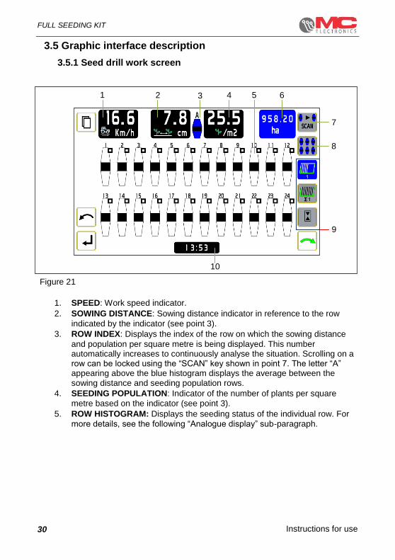
Figure 21
1. SPEED: Work speed indicator.
2. SOWING DISTANCE: Sowing distance indicator in reference to the row
indicated by the indicator (see point 3).
3. ROW INDEX: Displays the index of the row on which the sowing distance
and population per square metre is being displayed. This number automatically increases to continuously analyse the situation. Scrolling on a row can be locked using the “SCAN” key shown in point 7. The letter “A” appearing above the blue histogram displays the average between the sowing distance and seeding population rows.
4. SEEDING POPULATION: Indicator of the number of plants per square
metre based on the indicator (see point 3).
5. ROW HISTOGRAM: Displays the seeding status of the individual row. For
more details, see the following “Analogue display” sub-paragraph.
1 2 3 4 5 6
7
8
9
10

Instructions for use
FULL SEEDING KIT
31
6. VARIABLE RANGE: Variable indicators, based on the parameter selected
by the keys inside block 9. The list of possible displays includes:
- Partial processed area
- Total processed area
- Total hours worked
- Linear distance travelled
- Instantaneous yield
- Total hours worked
- Instantaneous herbicide rate
- Total herbicide distributed
- Activation of camera 1
7. SCAN: activates/deactivates scrolling of the fields for the distance and
population per row. Display touch screen key.
(For more details, see sub-paragraph 3.3.2.2)
8. DATA: Pressing this key once displays the sowing distance summary table
of all the seed sensors; pressing the same key again displays a second table with the seeding population values of every seed sensor. Display touch screen key.
(For more details, see sub-paragraph 3.3.2.2)
9. VARIABLE PARAMETERS: The displayable parameter icons are displays
on the “VARIABLE RANGE” (in blue) described in point 6. Display touch screen key.
(For more details, see sub-paragraph 3.3.2.2)
10. SYSTEM TIME

Instructions for use
FULL SEEDING KIT
32
3.5.1.1 Analogue display
The analogue display in histograms is based on the programmed sowing distance or seed life value (target) (see Programming chapter); the programmed value is assigned the reference of 100% and the histograms provide information concerning the quality of sowing detected, in the range of 100+/-50% according to the following screen :
The colouring of the histograms varies in relation to the alarm threshold set (see Programming chapter): the histogram remains green (or "neutral" until the sowing distance and seed life value detected remain within the programmed threshold, while it becomes red (with an alarm message) when the values detected exceed the threshold; in the following example the alarm threshold is set at 10%:
Number of rows
150% of the target population
(50% of the target sowing distance)
125% of the target population
(75% of the target sowing distance)
100% of the target population
(100% of the target sowing distance)
75% of the target population
(125% of the target sowing distance)
50% of the target population
(150% of the target sowing distance)
Probable "doubles"
Probable
“missing seeds”

Instructions for use
FULL SEEDING KIT
33
Row 4 is sowing within the
programmed alarm threshold
Row 4 is sowing at exactly at the programmed target value
Row 4 is sowing outside the
programmed alarm threshold
Instructions for use
FULL SEEDING KIT
34
3.5.1.2 Tabular display
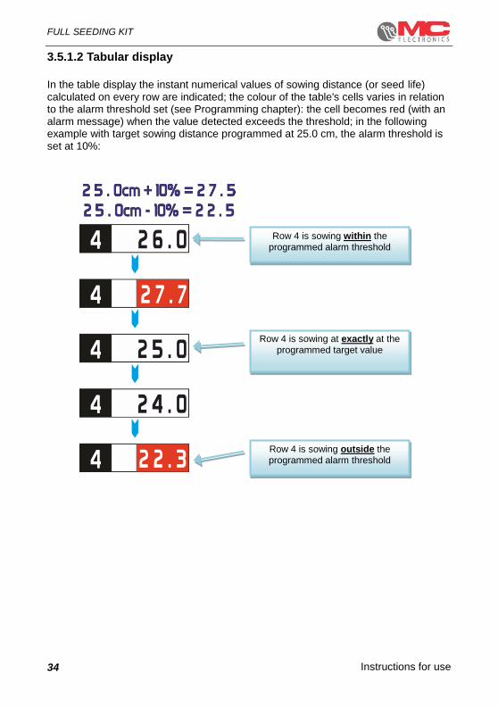
In the table display the instant numerical values of sowing distance (or seed life) calculated on every row are indicated; the colour of the table's cells varies in relation to the alarm threshold set (see Programming chapter): the cell becomes red (with an alarm message) when the value detected exceeds the threshold; in the following example with target sowing distance programmed at 25.0 cm, the alarm threshold is set at 10%:
Row 4 is sowing within the programmed alarm threshold
Row 4 is sowing at exactly at the programmed target value
Row 4 is sowing outside the programmed alarm threshold

Instructions for use
FULL SEEDING KIT
35
3.5.1.3 Display in PASSAGE mode
The Full seeding kit can work in COUNTER mode, as referred to by the information provided in the previous paragraphs, and in PASSAGE mode; in the latter mode, the sowing distance or seed life are not calculated but are only checked by the presence or not of pulses (for further details see the Programming chapter). In passage mode, the numerical indications of the sowing distance and seed life values are replaced by horizontal dashes; the conditions of normal work and alarms are shown in the following images.
Figure 22 Figure 23
Figure 24 Figure 25

Instructions for use
FULL SEEDING KIT
36
3.5.1.4 Fertiliser seed sensor display
Seed sensor signals for granular fertiliser are managed in ON/OFF mode, that is, the presence or not of pulses are checked; the fertilising seed sensors are however recognised when switched on and the alarm sounds when no pulse is detected for a period of time that can be programmed by the operator (see Programming chapter). Both in the histogram display as well as in the tabular display the fertiliser seed
sensors are identified with during normal operation and with in the event of
an alarm, as indicated in the following diagram:
Only the seed sensor has been detected on row 4
Both the seed sensor as well as the fertiliser seed
sensor have been detected on row 4 and the operation of both is
normal
Both the seed sensor as well as the fertiliser seed
sensor have been detected on row 4 and the
fertiliser seed sensor is
signalling an alarm

Instructions for use
FULL SEEDING KIT
37
3.5.1.5 Viewing the excluded rows from inspection
As described in paragraph “3.5 Automatic exclusion of inspection on the rows”, sowing and fertiliser control can be suspended on one or more rows, such as in the finishing manoeuvres on the edges of the field; the Full seeding kit will verify, in any case, the consistency of the signals from the seed sensors, emitting an alarm if one or more of the seed sensors on the excluded rows from the inspection should continue to send pulses (e.g. mechanical exclusion of the mechanism from the faulty row); note: this inspection is only active on the seed sensors and not on the fertiliser seed sensors;
below are some examples :
Row no. 12 was excluded from the
seed/fertiliser inspection and the seed
sensor is not detecting a pulse.
CORRECT
Row no. 12 was excluded from the
seed/fertiliser inspection but the exclusion
device was not activated or it did not work
and the seed sensor of row 12 is still
detecting the seeds;
ALARM
Row no. 12 was excluded from the
seed/fertiliser inspection but the exclusion
device was not activated or it did not work
and the seed sensor of row 12 is still
detecting the seeds and the sowing of row
12 is over the set target
ALARM
Row no. 12 was excluded from the
seed/fertiliser inspection but the exclusion
device was not activated or it did not work
and the seed sensor of row 12 is still
detecting the seeds and the sowing of row
12 is lower than the set target.
ALARM

Instructions for use
FULL SEEDING KIT
38
3.6 Automatic exclusion of inspection on the rows
You can set the Full Seeding kit to automatically consider one or more rows as excluded without acting as described in the previous paragraph;
this feature is active by default, however, this can be enabled or disabled in future software releases.
The automatic exclusion is only active when the machine is moving and the automation only works on the rows in alarm status and is activated by pressing the
Enter key : below is a practical example.
- A finishing is required due to the irregular shape of the field
- Therefore, the sowing inspection must be excluded first on row 8, then on row 7, then on row 6; after a few metres the sowing inspection must be reactivated first on row 6, then on row 7 and lastly on row 8;
Note: all the mechanical (or electronic) closing and reopening operations of the rows are assigned to the operator;
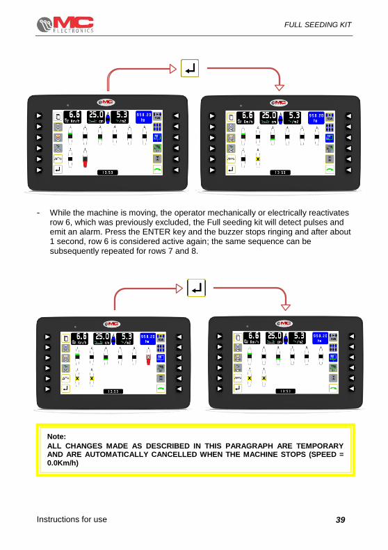
- While the machine is moving, the operator mechanically or electrically excludes row 8, and since the Full seeding kit will no longer detect pulses, an alarm will be emitted. Press the ENTER key and the buzzer stops ringing and after about 1 second, row 8 is considered to be excluded; the same sequence can be subsequently repeated for rows 7 and 6;
Instructions for use
FULL SEEDING KIT
39
- While the machine is moving, the operator mechanically or electrically reactivates row 6, which was previously excluded, the Full seeding kit will detect pulses and emit an alarm. Press the ENTER key and the buzzer stops ringing and after about 1 second, row 6 is considered active again; the same sequence can be subsequently repeated for rows 7 and 8.
Note:
ALL CHANGES MADE AS DESCRIBED IN THIS PARAGRAPH ARE TEMPORARY AND ARE AUTOMATICALLY CANCELLED WHEN THE MACHINE STOPS (SPEED = 0.0Km/h)

Instructions for use
FULL SEEDING KIT
40
4. Programming
In the Full Seeding kit there are 2 different type of programming available:
- Specific programming for the Virtual Terminal
- Specific programming for seeding ECU
THE 7” VIRTUAL TERMINAL MAY BE MATCHED TO DIFFERENT TYPES OF MC
ELETTRONICA ECUs (SOWING, SPRAYING, HAY-MAKING, ETC.) THEREFORE THE
GRAPHIC INTERFACE DEPENDS ON THE ECU CONNECTED AND IS DIFFERENT IN
DIFFERENT CASES, HOWEVER THERE ARE SOME GENERIC PARAMETERS THAT
APPLY TO ALL THE APPLICATIONS (E.G. METRIC OR IMPERIAL UNIT OF
MEASUREMENT) AND THAT ARE THUS PROGRAMMABLE IN THE VIRTUAL
TERMINAL WHILE THE SPECIFIC PARAMETERS FOR EACH APPLICATION (E.G.
SOWING DISTANCE) ARE PROGRAMMABLE IN THEIR RESPECTIVE ECUs VIA THE
VT;

Instructions for use
FULL SEEDING KIT
41
4.1 Virtual Terminal programming
This programming phase is accessible only when switched on, during initial testing when the screen display with the logo appears, with the sequence described below:
Figure 26
1. LANGUAGE: system operation language selection [Italian - English]
2. UNIT OF MEASUREMENT: selection of the type of unit of measurement to use.
[Metric (Km/h, ha, etc.) - Imperial (mph, A, etc.)]
3. BACKLIGHTING: display backlighting intensity adjustment [20-100%].
4. BUZZER VOLUME: buzzer volume adjustment.
[20-100%]
5. DIMMER: automatic "day" to "night" switching mode can be scheduled and vice
versa, the two modes are designed to optimise visibility during the day and not to excessively disturb the operator during evening or night work.
6. DATE: Current time
7. AUTOMATIC SHUTDOWN: Automatic shutdown of the system can be
programmed if the system remains on but unused (= absence of pulses from all the sensors, no button is pressed); after the time set in this parameter, the VT will send the command for general shutdown and the entire system turns off (consumption = mA) to not drain the tractor battery.
8. SOFTWARE UPDATE: VT software update.
1
2
3
4
5
6
7
888
Instructions for use
FULL SEEDING KIT
42
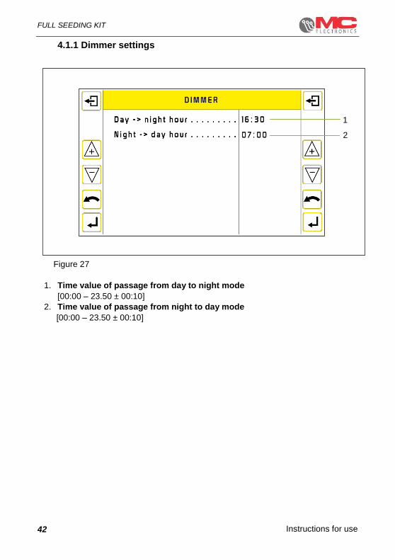
4.1.1 Dimmer settings
Figure 27
1. Time value of passage from day to night mode
[00:00 – 23.50 ± 00:10]
2. Time value of passage from night to day mode
[00:00 – 23.50 ± 00:10]
1
2

Instructions for use
FULL SEEDING KIT
43
4.1.2 Date and Time setting
Figure 28
1. Year [00 – 99 ± 1]
2. Month [01 – 12 ± 1]
3. Day [01 – 31 ± 1]
4. Hour [00 – 23 ± 1]
5. Minutes [00 – 59 ± 1]
1
2
3
4
5

Instructions for use
FULL SEEDING KIT
44
4.2 Seeding ECU programming
4.2.1 Main parameters
Figure 29
At any time during work it is possible to check the main programmed parameters; this information is shown on the menu page which is accessible by pressing the MENU key once. Below is a definition of the parameters summarising system setting:
1. OPERATING MODE: Indicates whether the operating mode has been defined
as “Counter” or “Passage”.
2. SOWING DISTANCE: indicates the distance programmed between one seed
and the next.
3. POPULATION: indicates the number of seeds programmed per square metre.
4. ALARM THRESHOLD: indicates the percentage value of the alarm threshold,
compared to the sowing distance value.
5. FERTILISER CONTROL: Indicates whether fertiliser passage control is
enabled \ disabled.
6. INTERROWS WIDTH: Indicates the set distance to keep between one
seeding row and the next.
1
2
3
4
5
6

Instructions for use
FULL SEEDING KIT
45
4.2.2 Menu
This programming phase is available at all times during work by pressing the menu button twice: the first press will display the main parameters currently scheduled (non-changeable) and with the second press of the menu button you will enter the programming menu.
Defining the parameters that make up this menu, we will have:
OPERATING MODE: The operating
mode defines how the sowing distance and population are calculated and checked. The Full seeding kit allows the operator to choose between COUNTER and PASSAGE mode.
COUNTER mode: the kit calculates and checks the sowing distance and seeding population for every row, counting the pulses coming from the seed sensors; this operating mode is recommended for work with medium/large sized seeds (e.g. corn, beetroot, soybean)
PASSAGE mode: the kit limits itself to
checking the presence of pulses coming from the seed sensors, calculation of the sowing distance or seeding population is NOT calculated. This operating mode is recommended for work with small seeds (e.g. rapeseed, vegetables);
COUNTER operating mode is
never active for the fertiliser seed
sensor signals, which are always
managed with PASSAGE
operating mode

Instructions for use
FULL SEEDING KIT
46
COUNTER MODE MENU: defines the seeding population and density calculation
parameters according to counter mode.
PASSAGE MODE MENU: sets the seeding population and density parameters
according to passage mode.
FERTILISER MENU: manages the fertiliser seed sensor operating and management
parameters.
SENSOR MENU: manages the operating and management parameters of the
various system operation sensors.
INTERROWS WIDTH: Program the width between the rows in cm (or inches); this
data is important both to calculate the area being worked on and to calculate the sowing distance and population. The Full seeding Kit automatically calculates the operating width, multiplying the interrows width data by the number of seed sensors acquired at start-up;
IT IS IMPORTANT THAT THE OPERATOR CHECKS THE CORRECT ACQUISITION OF THE SEED SENSORS EVERY TIME IT IS SWITCHED ON: AFTER INITIAL RECOGNITION THE SEED SENSORS THAT HAVE NOT BEEN DETECTED ARE NO LONGER MONITORED UNTIL IT IS NEXT SWITCHED ON
The most external rows detected are number 1
and number 12, therefore the calculated
work width will be:
interrows width X 12

Instructions for use
FULL SEEDING KIT
47
The most external rows detected are number 2
and number 11, therefore the calculated
work width will be:
interrows width X 10
The most external rows detected are number 1
and number 12, therefore the calculated
work width will be:
interrows width X 12
The most external rows detected are number 2
and number 12, therefore the calculated
work width will be:
interrows width X 11

Instructions for use
FULL SEEDING KIT
48
COUNTER SELECTED: The Full seeding Kit can manage up to 9 different sets of
totalisers independently, for total or partial processed area and for total litres of weed killer distributed. Each set of totalisers can be managed and reset separately from the others.
RPM MENU: enables and disables RPM sensor minimum and maximum threshold
monitoring and the respective alarms.
HERBICIDE MENU: sets the herbicide system operating parameters on the Full
seeding kit.
SEASON COUNTERS: two more overall counters are available, processed area and
hours worked; these counters are increased independently from the set of work counters selected; these counters indicate the total machine work.
RESERVED MENU: the screens contained in this sub-menu are protected by a
password that must be entered on a screen that appears when said screens open, as illustrated in figure 10.
Once the password has been entered correctly, the settings we will edit are necessary to adapt the system to the machine on which it is installed.
Instructions for use
FULL SEEDING KIT
49
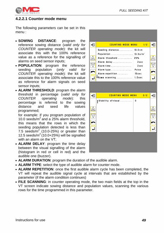
4.2.2.1 Counter mode menu
The following parameters can be set in this menu :
SOWING DISTANCE: program the reference sowing distance (valid only for COUNTER operating mode): the kit will associate this with the 100% reference value as a reference for the signalling of alarms on seed sensor inputs;
POPULATION: program the reference seeding population (only valid for COUNTER operating mode): the kit will associate this to the 100% reference value as reference for alarm signals on seed sensor inputs;
ALARM THRESHOLD: program the alarm
threshold in percentage (valid only for COUNTER operating mode): this percentage is referred to the sowing distance and seed life values programmed;
for example: if you program population of 10.0 seeds/m
2 and a 25% alarm threshold,
this means that the rows in which the seeding population detected is less than 7.5 seeds/m
2 (10.0-25%) or greater than
12.5 seeds/m2
(10.0+25%) will be signalled with an alarm on the VT;
ALARM DELAY: program the time delay
between the visual signalling of the alarm (histogram in red or cell in red) and the audible one (buzzer).
ALARM DURATION: program the duration of the audible alarm.
ALARM TYPE: select the type of audible alarm for counter mode.
ALARM REPETITION: once the first audible alarm cycle has been completed, the
VT will repeat the audible signal cycle at intervals that are established by the parameter (if the alarm condition continues)
FILE SCANNING: in counter operating mode, the two main fields at the top in the
VT screen indicate sowing distance and population values, scanning the various rows for the time programmed in this parameter.

Instructions for use
FULL SEEDING KIT
50
DISPLAY STABILITY: In the counting work mode, the display stability can be
increased or decreased; the higher the set value, the more stable the display will be, that is, only the more serious errors will be indicated. If the set number is low, the display will be less stable and minor errors will also be indicated

Instructions for use
FULL SEEDING KIT
51
4.2.2.2 Passage mode menu
Figure 30
The following parameters can be programmed in this menu:
1. SIGNAL DELAY: In passage mode, the sowing alarm sounds when a pulse is no
longer detected for the time programmed in this parameter; for example: programming this parameter at 3.0 seconds, the sowing alarm sounds if one or more seed sensors do not send pulses for at least 3.0 seconds.
2. ALARM DELAY: Program the time delay between the visual signalling of the
alarm (histogram in red or cell in red) and the audible one (buzzer)
3. ALARM DURATION: Program the duration of the audible alarm
4. ALARM TYPE: Select the Passage mode audible alarm type
5. ALARM REPETITION: Once the first audible alarm cycle has been completed,
the VT will repeat the audible signal cycle at intervals that are established by this parameter (if the alarm condition continues).
1
2
3
4
5

Instructions for use
FULL SEEDING KIT
52
4.2.2.3 Fertiliser menu
Figure 31
1. FERTILISER CONTROL: The Full seeding kit can be equipped with seed
sensors to detect granular fertilisers. This type of sensor works with a different kind of power supply than the seed sensors and requires specific wiring; depending on the type of crop/operation it is possible that the granular fertiliser is or is not distributed along with seeds. Thus, despite being assembled on the machine and electrically connected, the fertiliser seed sensors may not be required, in which case their monitoring can be excluded via this parameter.
2. SIGNAL DELAY: The fertiliser alarm sounds when a pulse is no longer
detected on one or more rows for the time programmed in this parameter; for example: programming this parameter to 3.0 seconds, the fertilising alarm sounds if one or more fertiliser seed sensors do not send pulses for at least 3.0 seconds.
3. ALARM DELAY: Program the time delay between the visual signalling of the
alarm (histogram in red or cell in red) and the audible one (buzzer).
4. ALARM DURATION: Program the duration of the audible alarm
5. ALARM TYPE: Select the type of audible alarm for the fertiliser
6. ALARM REPETITION: Once the first audible alarm cycle has been completed,
the VT will repeat the audible signal cycle at intervals that are established by this parameter (if the alarm conditions continue)
1
2
3
4
5
6

Instructions for use
FULL SEEDING KIT
53
4.2.2.4 Sensors menu
Figure 32
1. SPEED SENSOR: It is possible to program the number of pulses coming from
the speed sensor every linear 100 metres (or 330ft) covered by the machine; you can enter the parameter manually via manual calibration. Assuming that the speed sensor is located so as to detect 4 pulses for every rotation of the seed drill wheel:
1
2
3
4
5
No. of wheel revolutions ( e.g. 50 )
Mark a reference on the wheel
Distance covered (100 metres)
Finish point Starting point

Instructions for use
FULL SEEDING KIT
54
In this example, the parameter to be programmed is 100/2*4 = 200 pulses/100 metres
1. AREA LOCKED SENSOR: Normally the speed sensor is mounted on the seed
drill and during manoeuvres on the field, lifting the seed drill automatically stops the work area counter. Instead, if the sensor is mounted so as to continue to detect pulses during the manoeuvres on the field, it is possible to install a supporting sensor (typically a spring switch) that closes a contact to lock the
counting of the area; in this menu it is possible to enable or disable this sensor. 2. RPM SENSOR: Program the number of pulses per revolution coming from the
RPM fan sensor (if installed)
3. FLOWMETER SENSOR: Program the number of pulses per litre coming from the
flowmeter sensor (if installed) to detect the quantity of localised herbicide,
; we recommend running the practical test described below. Pour a pre-established (and as accurate as possible) amount of water into the tank, (e.g. 50 litres); make a note of the currently programmed value, e.g. 172.0
Reset the "total litres" totaliser by selecting and keeping the button pressed
Bring the localised herbicide system to normal working pressure and drain all the water from the tank. Check the litres displayed by the totaliser, for example 51 litres.
Apply the following formula:
In the example:
Program the new value obtained; 175.4 in the example;
Repeat the test following the same steps, making sure that the quantity displayed corresponds to what was actually introduced.

Instructions for use
FULL SEEDING KIT
55
4. SENSOR DIAGNOSTICS: In this menu you can check the electrical wiring of
various sensors, even when the machine is stopped. The screen shows all the available sensor types and the information displayed corresponds to the status of the sensors themselves, for example: by placing a metal reference in front of the speed sensor, it will go from "OFF" to "ON" and vice versa when the metal reference is removed. For the seed and fertiliser sensors, moving an obstacle (a finger or a screwdriver) in front of the sensor's optical parts, one at a time, you will see the numbers on the display corresponding to the sensor tested; furthermore,
moving the black selection bar with the and keys, the VT will emit an audible signal when its sensor moves from "OFF" to "ON".
Figure 33
Finish point
The lock area sensor is active, the corresponding menu row is selected, therefore the VT will emit an audible signal; all the remaining sensors are not active
Seed sensor no. 1 - 2 - 3 detects pulses, the VT emits an audible signal; all the remaining sensors
are not active.
The speed sensor detects a reference, but the related menu row is not selected therefore there is no corresponding audible signal

Instructions for use
FULL SEEDING KIT
56
4.2.2.4.1 Speed sensor
Figure 34
You can set and calibrate the speed sensor from this menu:
1. SPEED SOURCE: selects the speed source.
You can set the following configurations:
- ECU ESD: sensor connected to the Gateway ESD ECU
- MOD_4800: sensor connected to the seeding ECU, to be used if the ESD is not working.
- VT: sensor connected directly to the VT high frequency input; in this case, evaluate speed data transmission via can-bus
- Bridge module: to pick up the message from Isobus network or other source not compatible with CAN_2 or RS232 on VT
2. MANUAL CALIBRATION: you can manually indicate the speed sensor
calibration value;
3. AUTOMATIC CALIBRATION: run the automatic calibration procedure
1
2
3

Instructions for use
FULL SEEDING KIT
57
4.2.2.4.2 Speed sensor calibration
To run the speed sensor automatic calibration procedure, follow the path: User Settings > Speed Source, then press the AUTO key. This key can only be used when the “Calibration Ratio” field is selected.
The screen that is displayed is like the one shown in point 1. The steps to take for proper calibration are as follows:
1. Position 2 indicators on the ground at a distance of 100 metres from each other.
2. Take the tractor to a previously assigned reference point and press the ENTER key to start measuring.
3. Move forward with the tractor to the second assigned point and press ENTER again to stop measuring, like in point 2. If the pulses are not within the allowed interval, an error will be displayed like in point 3.
4. If the calibration procedure continues with no errors, the pulses accumulated on a 100 metre base will be displayed in the row under the words START - STOP.
Key Symbol Function
Starts / Stops pulse measurement for sensor calibration
①
②
③

Instructions for use
FULL SEEDING KIT
58
4.2.2.5 RPM menu
Figure 35
The following parameters can be programmed in this menu:
1. RPM ALARM: RPM monitoring can be enabled/disabled (for example, the fan if
the corresponding sensor is present), so that the Full Seeding kit signals the alarm.
2. ALARM DELAY: programs the minimum time for which the RPMs detected must
be less than the minimum threshold (RPM MIN) or higher than the maximum threshold (RPM MAX) to trigger the alarm signal.
3. ALARM DURATION: sets the duration of the RPM audible alarm signal.
4. ALARM TYPE: sets the type of RPM audible alarm.
5. MIN RPM: programs the minimum threshold under which the RPM alarm trips
(if enabled).
6. MAX RPM: programs the maximum threshold over which the RPM alarm trips
(if enabled).
1
2
3
4
5
6
Instructions for use
FULL SEEDING KIT
59
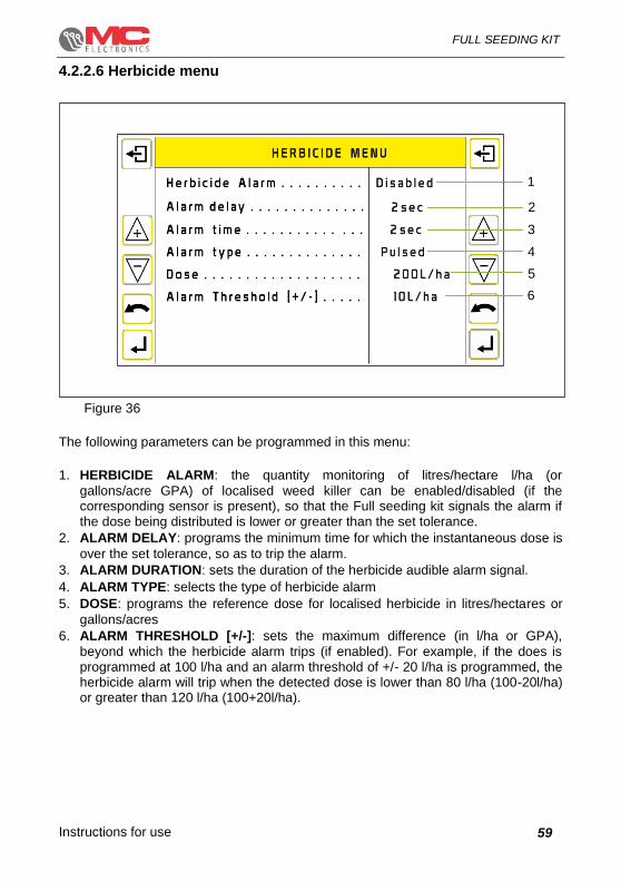
4.2.2.6 Herbicide menu
Figure 36
The following parameters can be programmed in this menu:
1. HERBICIDE ALARM: the quantity monitoring of litres/hectare l/ha (or
gallons/acre GPA) of localised weed killer can be enabled/disabled (if the corresponding sensor is present), so that the Full seeding kit signals the alarm if the dose being distributed is lower or greater than the set tolerance.
2. ALARM DELAY: programs the minimum time for which the instantaneous dose is
over the set tolerance, so as to trip the alarm.
3. ALARM DURATION: sets the duration of the herbicide audible alarm signal.
4. ALARM TYPE: selects the type of herbicide alarm
5. DOSE: programs the reference dose for localised herbicide in litres/hectares or
gallons/acres
6. ALARM THRESHOLD [+/-]: sets the maximum difference (in l/ha or GPA),
beyond which the herbicide alarm trips (if enabled). For example, if the does is programmed at 100 l/ha and an alarm threshold of +/- 20 l/ha is programmed, the herbicide alarm will trip when the detected dose is lower than 80 l/ha (100-20l/ha) or greater than 120 l/ha (100+20l/ha).
1
2
3
4
5
6
Instructions for use
FULL SEEDING KIT
60
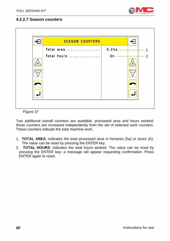
4.2.2.7 Season counters
Figure 37
Two additional overall counters are available, processed area and hours worked; these counters are increased independently from the set of selected work counters. These counters indicate the total machine work.
1. TOTAL AREA: indicates the total processed area in hectares (ha) or acres (A).
The value can be reset by pressing the ENTER key.
2. TOTAL HOURS: indicates the total hours worked. The value can be reset by
pressing the ENTER key; a message will appear requesting confirmation. Press ENTER again to reset.
1
2

Instructions for use
FULL SEEDING KIT
61
4.2.2.8 Reserved menu
Figure 38
To enter the password, you must use the ▼▲ keys to select the number, starting from the most significant digit, and confirming the desired value with the ENTER key. The procedure must be repeated for the 4 digits that make up the password. Pressing the ENTER key on the last digit verifies the entered credentials. If the password is not correct, the system automatically goes back to the “Menu” screen.

Instructions for use
FULL SEEDING KIT
62
Figure 39
1. TOTAL HOURS: Total hours worked
2. h<8 Km/h: Indicates the number of hours worked at speeds greater than 8
Km/h
3. h>8 Km/h: Indicates the number of hours worked at speeds lower than 8 Km/h
4. TOTAL AREA: Total processed area
5. MAX SPEED: Maximum allowed speed
6. BAR GRAPH SENSITIVITY: Main screen graphic sensitivity
7. ROW AUTO-EXCLUSION: File exclusion enabling / disabling
1
2
3
4
5
6
7

Instructions for use
FULL SEEDING KIT
63
5. Software updates
MC Elettronica products are continuously being developed and it is possible for new functions to be added or existing ones to be further improved. For this reason, the Virtual Terminal software and/or the seeding ECU software can be updated directly from the www.mcelettronica.it site in the download section or requested directly from MC Elettronica Service;
The Virtual Terminal has an input for a memory card (SD card) housed on the lower edge, included in the supply. If the SD card is lost, you can use a standard one, provided that it is NOT an HC (High-Capacity) type;
generally the types of files to be used for updates can be of 2 types :
- HEX type files: contain operating programs with Virtual Terminal or ECU
functions
- DAT type files: contain the graphics (images and drawings) specific to the
Virtual Terminal
SD memory card housing
BEFORE CARRYING OUT THE VIRTUAL TERMINAL OR ECU SOFTWARE UPDATE, CHECK THAT ON THE DEVICE'S SD CARD THERE ARE ONLY THE FILES TO BE UPDATED, OTHERWISE THE UPDATING PROCESS MAY NOT BE AVAILABLE

Instructions for use
FULL SEEDING KIT
64
5.1 Virtual Terminal software update
1) To update the system, you must use the SD card supplied along with the USC Kit.
Figure 40
2) Insert the SD card in the slot at the base of the VT. At this point, make sure that the screen is off and take care not to damage the card slot when inserting the card.
Figure 41
3) Access the Bootloader screen by holding down the ON + 1 and 2 keys shown in figure 29 at the same time.
INSERT SD CARD
Figure 42
1
2
Instructions for use
FULL SEEDING KIT
65
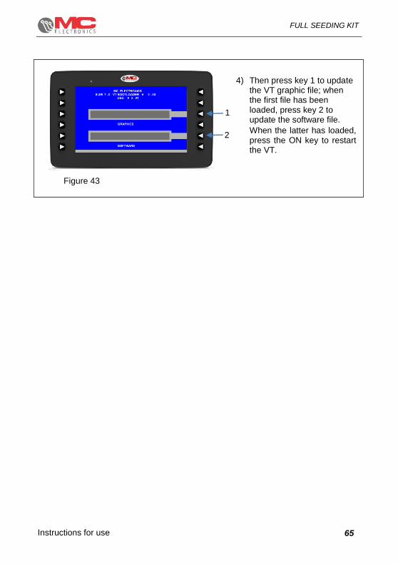
4) Then press key 1 to update the VT graphic file; when the first file has been loaded, press key 2 to update the software file.
When the latter has loaded, press the ON key to restart the VT.
1
2
Figure 43

Instructions for use
FULL SEEDING KIT
66
5.1.1 ECU software update
1) Put the ECU_TL01.hex file on the SD card that is in the USC kit if, for example, you wish to update the Tram Line control unit firmware. Keep in mind that at this point, there must be no other files.
Figure 44
Figure 31 2) Turn on the VT and access the user settings
by holding down the MENU key for 4 seconds. After having displayed the user settings screen, scroll using the DOWN key. Use the ENTER key to confirm the item “Software Update”. A screen like the one to the side will be displayed. Using the UP and DOWN keys, scroll through the list of update files on the SD card.
Figure 45
Figure 32 3) Confirm with ENTER and wait for the updates
to load. When the update is over, the VT will restart automatically.
Figure 46

Instructions for use
FULL SEEDING KIT
67
6. Programmable parameters
Field Unit Minimu
m Maximu
m Resolution Default
Backlighting % 20 100 1 100
Buzzer volume % 20 100 1 100
Language - 0 6 1 0
Unit of measurement - 0 1 1 0
Operating mode - 0 1 1 0
Sowing distance (Counter)
cm 0.1 99.9 0.1 10.0
Seeding population (Counter)
seeds/m2 0.1 99.9 0.1 13.3
Total hours h 0 65535 1 0
Speed calibration coefficient
Pulses/m 0.30 9.99 0.01 2
Total area ha 0.0 9999.9 0.1 0
Alarm threshold (Counter)
% 10 50 1 25
Alarm delay (Counter) s 0 12 1 4
Alarm duration
(counter) s 1 10 1 2
Alarm type
(Counter) - 1 2 1 1
Alarm repetition
(Counter) s 10 240 1 15
Row scan
(Counter) s 0.2 12.0 0.1 2.0
Display stability
(Counter) - 0 50 1 0
Hours h 0 23 1 0
Minutes min 0 59 1 0
Day/night dimmer h
min
0
0
23
50
1
10
5
0

Instructions for use
FULL SEEDING KIT
68
Field Unit Minimu
m Maximu
m Resolution Default
Signal delay
(Passage) s 1.0 10.0 0.1 4.0
Alarm delay
(Passage) s 0 12 1 4
Alarm duration
(Passage) s 1 10 1 2
Alarm type
(Passage) - 1 2 1 1
Alarm repetition
(Passage) s 10 240 1 15
Fertiliser control (Fertiliser)
- 1 2 1 2
Signalling delay (Fertiliser)
s 1.0 10.0 0.1 4.0
Alarm delay
(Fertiliser) s 0 12 1 2
Alarm duration
(Fertiliser) s 1 10 1 4
Alarm type
(Fertiliser) - 1 2 1 1
Alarm repetition
(Fertiliser) s 10 240 1 15
Area locked sensor - 1 2 1 2
RPM sensor Pul/rev 1.0 20.0 0.1 2.0
Flowmeter sensor Pul/litre 10.0 999.9 0.1 172.0
Counter selected - 1 9 1 1
RPM alarm - 1 2 1 2
RPM alarm delay s 0 12 1 2
RPM alarm duration s 1 12 1 2
RPM alarm type - 1 2 1 1
RPM minimum threshold
RPM 0 9999 1 200
RPM maximum threshold
RPM 0 9999 1 2000
Herbicide alarm - 1 2 1 2
Alarm delay
(Herbicide)
s 0 12 1 2
Alarm duration s 1 12 1 2

Instructions for use
FULL SEEDING KIT
69
(Herbicide)
Field Unit Minimu
m Maximu
m Resolution Default
Alarm type
(Herbicide) - 1 2 1 1
Reference value (Herbicide)
l/ha 0 9999 1 200
Alarm threshold
(Herbicide) l/ha 1 999 1 10
Speed source - 1 4 1 1
Instructions for use
FULL SEEDING KIT
70
7. Alarms
The alarms are always displayed based on the priority of the message. They are following by a modulated audible signal to get the operator’s attention regarding the problem that is then displayed on the screen.
When an alarm is generated in the Full seeding kit, it can be due to various parameters that the system monitors during machine operation. The sensitivity, duration and tolerance threshold are defined in the specific programming menus described in paragraph 4.
The events that generate an alarm are listed below:
The operating mode set to “Counter” allows us to make sure that the sowing
distance and the seeding population correspond to the values the operator wants. Instead, if set to “Passage”, the system verifies whether the seed passes within a certain interval.
The Full Seeding kit can be equipped with seed sensors for fertiliser passage;
if it does not pass within a set time, it generates an alarm signal; the same goes
for herbicide distribution monitoring.

Instructions for use
FULL SEEDING KIT
71
8. Maintenance
This chapter gives instructions on how to carry out ordinary and extraordinary maintenance.
Routine maintenance refers to those operations which must be carried out
periodically. As they do not require specific skills, they can be carried out by the users (operators, etc.).
Special maintenance refers to unforeseeable operations due to mechanic or electric
failures. They require specific technical skills, so they should be exclusively carried out by qualified personnel (maintenance personnel etc.).
8.1 Routine maintenance
Ordinary maintenance consists in cleaning the instrument.
Clean the instrument with a wet cloth and mild detergent to avoid erasing the serigraphs on the panel.
!
Warning
Do not use pressure water jets.
Do not use abrasive products, solvents or alcohol.
Do not use hard pointed objects to press on the keyboard.
8.1.1 How to protect the main connector
If the monitor is not used for a long time, disconnect the main signal connector from the wiring. We recommend isolating both connectors (of the monitor and of the wiring harness) with Nylon. If they are not disconnected, no protection is needed.
Instructions for use
FULL SEEDING KIT
72
9. Troubleshooting
In case of appliance malfunctioning, perform the simple checks below to find out what you need to do.
If the problem still remains after carrying out the suggested checks, contact your local dealer or MC elettronica Technical Service.
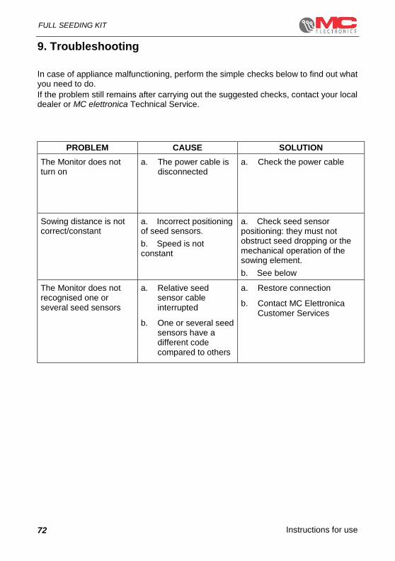
PROBLEM CAUSE SOLUTION
The Monitor does not turn on
a. The power cable is disconnected
a. Check the power cable
Sowing distance is not correct/constant
a. Incorrect positioning of seed sensors.
b. Speed is not constant
a. Check seed sensor positioning: they must not obstruct seed dropping or the mechanical operation of the sowing element.
b. See below
The Monitor does not recognised one or several seed sensors
a. Relative seed sensor cable interrupted
b. One or several seed sensors have a different code compared to others
a. Restore connection
b. Contact MC Elettronica Customer Services

Instructions for use
FULL SEEDING KIT
73
10. Technical data
10.1 7” Virtual Terminal
Power supply voltage : 12-24 Vdc
Maximum absorbed current (excluding sensors)
: 700 mA ( 12V )
350 mA ( 24V )
Operating features
Protection degree : IP65
Mechanical vibrations resistance : 2G
Operating conditions
Room temperature : -20°C ÷ +70°C
Weather conditions : Relative humidity 80%
Transport and storage
Temperature : -25°C ÷ +75°C
10.2 ECU-SEM
Power supply voltage : 10 – 16 Vdc
Absorbed current in stand-by : < 200 uA
Maximum energy consumption : 3.5 A
Operating temperature : -20°C ÷ +70°C
Protection degree : IP65
Inputs : 24 x 1 Khz max NPN inputs
: 2 x 3 Khz max NPN inputs
: 1 x 500 Khz max NPN inputs
: 1 x 1.5 Khz max Namur inputs
Sensor power supply output : 1 x 12V 1A max
: 1 x 8V 2A max
Status LED : 1 x Red/Green Bi-LED
Communication line : 1 x CAN BUS 2.0B ( bit rate: 500 Kbit/s )

Instructions for use
FULL SEEDING KIT
74
10.3 ECU gateway
Power supply voltage : 10 – 16 Vdc
Max consumption only ECU : 400 uA
Operating temperature : -20°C ÷ +70°C
Protection rating : IP67
Communication line : 2 x CAN BUS 2.0B
Dimension : 119 x 134 x 35
10.4 Accessories
10.4.1 Pipe seed sensors
Power supply voltage : 8 - 10 Vdc
Output signal : 70 mA
Working temperature : - 20°C / +70°C
Protection degree : IP 67
10.4.2 Bracket seed sensors
Power supply voltage : 8 - 10 Vdc
Rated current : 70 mA
Working temperature : - 20°C / +70°C
Protection degree : IP 67
10.4.1 Proximity inductive sensor
Power supply voltage : 12 Vdc
Output signal : NPN
Working temperature : - 25°C / +75°C
Max. operation distance : 4 mm
Protection degree : IP 67

Instructions for use
FULL SEEDING KIT
75
10.4.2 Magnetic sensor
Output signal : Contact to ground
Max. working frequency : 100 Hz
Working temperature : - 25°C / +70°C
Max. operation distance : 10 mm (with 12 magnet)
Protection degree : IP 67

Instructions for use
FULL SEEDING KIT
76
CAUTION!!
DO NOT WASH USING A POWER WASHER
WITH PRESSURE JET.
QUESTO PRODOTTO CONTIENE STAGNO E PIOMBO, A FINE CICLO DI VITA DEVE
ESSERE SMALTITO NELLE AREE ADIBITE AL RITIROOPPURE CONSEGNATO DIRETTAMENTE PRESSO
LA SEDE MC ELETTRONICA SRL (ITALY)
WARNING: THIS PRODUCT CONTAINS TIN AND LEAD.
IT MUST BE DISPOSED OF AT THE END OF ITS LIFE CYCLE AT THE DESIGNATED DISPOSAL FACILITIES OR DELIVERED DIRECTLY TO MC ELETTRONICA SRL (ITALY).

Instructions for use 77
FULL SEEDING KIT

Printed in Italy

Instructions for use 79
FULL SEEDING KIT

Printed in Italy
www.mcelettronica.it
Electronic equipment for agriculture