full-range frp failure behaviour in rc beams shear
TRANSCRIPT

Accepted Manuscript
Full-range FRP failure behaviour in RC beams shear-strengthenedwith FRP wraps
G.M. Chen , S.W. Li , D. Fernando , P.C. Liu , J.F. Chen
PII: S0020-7683(17)30336-0DOI: 10.1016/j.ijsolstr.2017.07.019Reference: SAS 9665
To appear in: International Journal of Solids and Structures
Received date: 30 November 2016Revised date: 15 May 2017Accepted date: 20 July 2017
Please cite this article as: G.M. Chen , S.W. Li , D. Fernando , P.C. Liu , J.F. Chen , Full-range FRPfailure behaviour in RC beams shear-strengthened with FRP wraps, International Journal of Solids andStructures (2017), doi: 10.1016/j.ijsolstr.2017.07.019
This is a PDF file of an unedited manuscript that has been accepted for publication. As a serviceto our customers we are providing this early version of the manuscript. The manuscript will undergocopyediting, typesetting, and review of the resulting proof before it is published in its final form. Pleasenote that during the production process errors may be discovered which could affect the content, andall legal disclaimers that apply to the journal pertain.

ACCEPTED MANUSCRIPT
ACCEPTED MANUSCRIP
T
Highlights
Full-range failure behaviour of FRP wraps for shear-strengthening RC beams
Progressive failure process involving both debonding and rupture of FRP
An analytical solution, validated by finite element analysis, is developed
Development of shear contribution by FRP with crack opening quantified

ACCEPTED MANUSCRIPT
ACCEPTED MANUSCRIP
T
Full-range FRP failure behaviour in RC beams
shear-strengthened with FRP wraps
G.M. Chen a, S.W. Li
b, D. Fernando
c, P.C. Liu
a and J.F. Chen
d,e*
a School of Civil and Transportation Engineering, Guangdong University of
Technology, Guangzhou, China.
b Guangzhou Power Supply Bureau, China Southern Power Grid Co. Ltd., Guangzhou,
China.
c School of Civil Engineering, Faculty of Engineering, Architecture and Information
Technology, The University of Queensland.
d College of Civil Engineering and Architecture, Wenzhou University, China.
e School of Natural and Built Environment, Queen‟s University Belfast, Belfast BT9
5AG, UK.
*Corresponding author. Tel.: +44 28 9097 4184; fax: +4428 9097 4278;
E-mail address: [email protected] (J.F. Chen)

ACCEPTED MANUSCRIPT
ACCEPTED MANUSCRIP
T
Abstract: Reinforced concrete (RC) beams can be strengthened in shear by externally
bonded (EB) fibre reinforced polymer (FRP) composites in the forms of side-bonded
FRP strips, FRP U-jackets or FRP wraps. The shear failure of almost all RC beams
shear-strengthened with FRP wraps and some of the beams strengthened with FRP
U-jackets, is due to the rupture of FRP. For an FRP wrapped beam with FRP bonded
to the beam surface, debonding of EB FRP from concrete substrate usually precedes
the ultimate FRP rupture failure, therefore the failure process of the beam is
associated with both FRP debonding and rupture failures. Despite extensive research
in the past decade, there is still a lack of understanding of how the failure of FRP
wraps in such an FRP-strengthened beam progresses and how it affects the shear
behaviour of the beam. This paper presents an analytical study on the progressive
failure of FRP wraps in such strengthened beams. In this study, the debonding and the
subsequent rupture processes are derived and the FRP contribution to the shear
capacity of the beam is quantified. The analytical solution is verified by comparing its
predictions with the predictions of a finite element model. An additional merit of the
analytical solution is that the development of FRP shear contribution with the opening
of the shear crack can be quantitatively determined, providing a useful tool for further
investigation on the shear interaction among different components (FRP, shear
reinforcements, steel shear reinforcements, and concrete) in RC beams
shear-strengthened with FRP.

ACCEPTED MANUSCRIPT
ACCEPTED MANUSCRIP
T
Keywords: Fibre reinforced polymers (FRP); Reinforced concrete beams;
Strengthening; Shear failure; Shear strength; FRP Debonding; FRP Rupture; Stress
distribution; Shear interaction
ACCEPTED MANUSCRIPT
ACCEPTED MANUSCRIP
T
1. Introduction
Externally bonded (EB) fibre-reinforced polymer (FRP) reinforcement has been
increasingly used to enhance the shear resistance of reinforced concrete (RC) beams
in the past two decades due to its unique advantages including high strength-to-weight
ratio, excellent corrosion resistance, and ease of installation (Bank, 2006; Hollaway
and Teng, 2008; Oehlers and Seracino, 2004). Shear strengthening of RC beams using
EB FRP can be achieved in different ways by: (1) bonding FRP laminates around the
entire beam section (referred to as “FRP wraps” hereafter), (2) bonding FRP laminates
to the two sides as well as the tension face of the beam (referred to as “U-strips”
hereafter), and (3) bonding FRP laminates to the two sides of the beam only (referred
to as “side strips” hereafter) (Teng et al., 2002). In RC beams strengthened with EB
FRP, FRP debonding failure is a typical failure mode, where FRP is detached from the
concrete substrate with a thin layer of concrete bonded to the debonded surface of
FRP. RC beams shear-strengthened with FRP side strips, or strengthened with U-strips
predominantly fail due to the debonding of FRP strips from the beam sides (Chen and
Teng, 2003a, b; Teng and Chen, 2009). However, often the failure of RC beams shear
strengthened with FRP wraps (Jirawattanasomkul et al., 2013; Teng et al., 2009) and
in some cases with FRP U-jackets [e.g. FRP U-jackets with anchorage (Chen et al.,
2016; Kim et al., 2014; Mofidi et al., 2012)], are due to the rupture of FRP, usually
preceded by FRP debonding (Cao et al., 2005; Teng et al., 2009).
Extensive studies carried out over the past two decades on RC beams

ACCEPTED MANUSCRIPT
ACCEPTED MANUSCRIP
T
shear-strengthened with EB FRP (Bousselham and Chaallal, 2004, 2006a, b, 2008,
2009; Carolin and Taljsten, 2005a; Islam et al., 2005; Khalifa et al., 1998; Khalifa and
Nanni, 2000, 2002; Leung et al., 2007; Matthys, 2000; Monti and Liotta, 2007;
Pellegrino and Modena, 2002, 2006, 2008; Taljsten, 2003; Triantafillou, 1998) have
led to many design models (Carolin and Taljsten, 2005b; Chaallal et al., 1998; Chajes
et al., 1995; Chen and Teng, 2003a, b; Khalifa et al., 1998; Mofidi and Chaallal, 2011;
Monti and Liotta, 2007; Pellegrino and Modena, 2002, 2006, 2008; Taljsten, 2003;
Triantafillou, 1998; Triantafillou and Antonopoulos, 2000; Ye et al., 2005), some of
which have been adopted in design guidelines (ACI-440.2R, 2008; CNR-DT-200R1,
2013; Concrete-Society, 2012; fib, 2001; GB50608-2010, 2010; HB305, 2008; JSCE,
2001). The majority of these existing design models have assumed that the shear
capacity of the EB FRP shear-strengthened beam (Vu ) is a sum of the shear
contributions of concrete (Vc), steel shear reinforcements (Vs ) and shear strengthening
FRP (Vf) based on simple superposition (i.e. Vu = Vc + Vs + Vf). However, all three
components may not reach their peak values (Vc , Vs , Vf ) simultaneously and adverse
shear interaction may exist among them during the failure process of the strengthened
beam, thus resulting in a shear strength less than the summation of the maximum
shear contribution of each component (Ali et al., 2006; Bousselham and Chaallal,
2004, 2006a, b, 2008; Chen, 2010; Chen et al., 2012, 2013; Chen et al., 2010; Denton
et al., 2004; Khalifa and Nanni, 2000, 2002; Li et al., 2001, 2002; Park et al., 2001;
Pellegrino and Modena, 2002, 2006, 2008; Teng et al., 2002; Teng et al., 2004).
In RC beams shear strengthened using EB FRP and failing due to FRP debonding,

ACCEPTED MANUSCRIPT
ACCEPTED MANUSCRIP
T
an adverse shear interaction usually exists between the external FRP (Vf) and internal
steel shear reinforcements (Vs) (Ali et al., 2006; Chen, 2010; Chen et al., 2012, 2013;
Chen et al., 2010) as explain next. Due to the brittle nature of debonding failures, the
width of the critical shear crack is usually small upon the occurrence of FRP
debonding failure; as a result, some of the internal steel shear reinforcements
intersected by the critical shear crack may not reach yielding (as demonstrated in
Chen et al. (2010)) as assumed in most of the existing studies except a few which
duly considered the shear interactions (Ali et al., 2006; Chen et al., 2012, 2013;
Pellegrino and Modena, 2002, 2006, 2008). Among the few studies considering the
shear interaction, Chen et al. (2012) presented a closed-form solution for the
full-range debonding process of FRP side strips and U strips, allowing different stages
of the shear debonding failure to be understood and the shear contribution of FRP at
different stages quantitatively determined. By evaluating the development of shear
resistance contributed by both external shear-strengthening FRP (based on the
solution of Chen et al. (2012)) and internal steel shear reinforcements as the critical
shear crack widens, Chen et al. (2013) developed a new shear strength model
considering the adverse shear interaction between the internal steel shear
reinforcement and the external FRP; the model provides improved predictions of the
shear strength of FRP shear-strengthened RC beams where FRP debonding governs.
In RC beams shear strengthened using EB FRP and failing due to FRP rupture, the
adverse shear interaction exists mainly between the external FRP (Vf ) and concrete
(Vc), which can be qualitatively explained as follows. As debonding of FRP strips on

ACCEPTED MANUSCRIPT
ACCEPTED MANUSCRIP
T
the beam sides generally precedes the eventual FRP rupture failure as experimentally
observed by Cao et al. (2005) and Teng et al. (2009), it can be reasonably assumed
that the average strain developed in the FRP along the critical shear crack is
proportional to the maximum shear crack width. Based on this assumption, it can be
easily inferred that the average strain in FRP is also affected by the beam size: the
larger the beam size the larger the shear crack width at the FRP rupture failure, and
thus the larger degradation of concrete shear resistance mechanism (i.e. larger
reduction of Vc). Note that the average strain in FRP is usually termed the effective
FRP strain following Chen and Teng (2003a,b). Given the relatively large failure
strain of FRP composites compared to the yield strain of normal steel (Teng et al.
2002), the crack width at FRP rupture failure may be large enough to cause the
yielding of steel shear reinforcements but compromise the shear resistance mechanism
in concrete including the friction along the cracked concrete surfaces, concrete
aggregate interlock and dowel action, and thus cause a degradation in cV (Teng et al.,
2002; Triantafillou and Antonopoulos, 2000). This phenomenon was first observed in
FRP-wrapped columns under cyclic loading (Priestley et al., 1996; Priestley and
Seible, 1995). More recently, the existence of this adverse shear interaction was
clearly observed by Teng et al. (2009) and Jirawattanasomkul Jirawattanasomkul et al.
(2013) in RC beams shear-strengthened by FRP wraps and by Chen et al. (2016) in
RC beams shear-strengthened with well-anchored FRP U-strips (failing by FRP
rupture). Using accurately measured FRP strains, it was shown that the concrete shear
contribution started to decrease while that of FRP was still increasing. In particular, at

ACCEPTED MANUSCRIPT
ACCEPTED MANUSCRIP
T
the ultimate state of the strengthened beams, the effective strain in FRP intersected by
the critical shear crack was found to be 24%-56% of FRP rupture strain (Chen et al.
2016). When FRP with large rupture-strain (e.g. >6%) was used, shear contribution of
concrete was found to degrade by 056.4%, depending on the amount of FRP used,
shear-span to beam depth ratio, and the member size (Jirawattanasomkul et al., 2013).
Based on the limited test results of small specimens (Khalifa et al., 1998; Priestley
and Seible, 1995), existing guidelines normally recommend a strain limit in the range
of 0.004 0.006 (e.g. 0.004 in ACI 440-2R (2008) and 0.006 in fib (2001)), to avoid a
significant degradation of the concrete shear resistance. Whilst this limit provides a
convenient design provision, it does not necessarily prevent the development of wide
cracks (see Denton et al., 2004), especially for large beams as discussed above.
Therefore, quantitative evaluation of the shear contribution of FRP throughout the
failure process of RC beams shear-strengthened with EB FRP is important for
achieving a better understanding of the shear resistant mechanism of EB FRP,
especially for developing a shear strength model capable of accurately considering the
shear interaction among concrete, internal steel and EB FRP. For FRP debonding
failure (of FRP side strips and U strips), such research had been done by the authors
using an analytical solution in Chen et al. (2012). This paper presents a closed-form
solution for the entire failure process of FRP wraps used to enhance the shear
resistance of RC beams where FRP rupture failure usually governs, allowing the
different stages of failure to be clearly explained and understood. A particularly
important outcome of the solution is the explicit expressions that describe the

ACCEPTED MANUSCRIPT
ACCEPTED MANUSCRIP
T
development of shear contribution of externally bonded FRP wraps as the critical
shear crack widens. An additional merit of the closed-form solution is that it can be
directly employed in investigating the effect of shear interaction on the shear strength
of FRP shear-strengthened RC beams where FRP rupture failure governs. It should be
noted that although the solution is developed specifically for FRP wraps, it is also
applicable to other FRP shear-strengthening schemes failing by FRP rupture, such as
RC beams shear-strengthened with well-anchored FRP U-strips (Chen et al., 2016;
Kim et al., 2014; Mofidi et al., 2012). In the following sections, the basic assumptions
of the solution is first presented, followed by solutions for different stages during the
failure process which are then validated by comparing the predictions of the solutions
with finite element (FE) predictions.
2. Basic assumptions
The basic assumptions adopted herein are exactly the same as those assumed for
FRP U strips and side strips which are detailed in Chen et al. (2012). As in (Chen et
al., 2012), the external FRP shear reinforcement is assumed to be in the form of
discrete strips for consistency without loss of generality. This means that the
analytical solution is exact for FRP shear reinforcement in the form of discrete narrow
FRP strips with zero net gaps, but is approximate for discrete FRP strips with
non-zero gaps or continuous FRP sheets as the approach neglects the interactions
between the bonded fibres. It is further assumed that the failure process of the FRP
shear-strengthened beam is dominated by the initiation and widening of a single

ACCEPTED MANUSCRIPT
ACCEPTED MANUSCRIP
T
dominant shear crack (termed as “critical shear crack” hereafter) although other
secondary cracks may exist in practice which are usually less critical as shown in
(Chen et al., 2007; Teng et al., 2006). It is also assumed that the bond-slip behaviour
of the FRP-to-concrete bonded interface is governed by the linearly softening
bond-slip model (Fig. 3(a)). The solution presented here as well as that in Chen et al.
(2012) are different from the solution of Monti et al. (2004) [see also Liotta (2006) for
details] in a number of significant aspects as explained in Chen et al. (2012). The
essential difference lies in that the present solution aims to find the full-range failure
behaviour of FRP while the critical shear crack widens, while Monti et al. (2004) only
attempted to obtain the maximum effective stress in FRP strips and hence the FRP
contribution to the shear capacity of the strengthened beam at the ultimate state.
3. Modelling the behaviour of shear-strengthening FRP using FRP-to-concrete
bonded joints
The present analytical solution is developed based on analytical solutions for the
full-range behaviour of FRP-to-concrete bonded joints with either free (type A joint)
and fixed (type B joint) far end as presented in Chen et al. (2012), with only the bond
behaviour in the fibre direction of the FRP considered (Fig. 1). As explained in Chen
et al. (2012), an FRP U-strip in a shear-strengthened RC beam can be represented
with a type A joint representing the FRP-to-concrete bonded interface above the
effective shear crack, connected at the location of the effective shear crack to a type B
joint representing the interface below the effective shear crack (Figs 1 and 2).

ACCEPTED MANUSCRIPT
ACCEPTED MANUSCRIP
T
Similarly, an FRP wrap can be well represented by two type B joints above and below
the effective shear crack respectively, with their far ends fixed at the beam top and
bottom, and connected with each other at the location of the effective shear crack
(Figs 1 and 2). If an FRP U-strip is well-anchored (i.e. fixed) at the upper end, it can
also be represented by two type B joints above and below the effective shear crack as
with the FRP wrap except that the fixed upper end of FRP is usually not at the beam
top. For the convenience of understanding, a summary of the solution of the full-range
behaviour of type B joint is presented next. Further details of the solution can be
found in Chen et al. (2012).
The full-range load-displacement response of a type B joint can be characterized
by key points O, B‟, D‟ and P‟ when the FRP bond length L is small [i.e. uL a ,
where 2
ua
is the effective bond length of FRP,
1f
f f fE t
is a
dimensionless constant defined to qualify the effective bond length, f and f are
the maximum interfacial shear stress and maximum interfacial slip of the
FRP-to-concrete bonded interface, as shown in Fig. 3(a)], and by key points O, A, B
and P when the bond length is large ( uL a ) as schematically shown in Fig. 3(b).
Accordingly, the full range load-displacement response (i.e. - P ) can be divided
into three segments, namely segments 'OB , ' 'B D , ' 'D P for uL a and OA , AB
and BP for uL a . The interfacial shear stress distributions along the
FRP-to-concrete interface experienced by a type B joint during the loading process
are schematically shown in Fig. 4 for uL a and in Fig. 5 for uL a , corresponding
to the different stages of the load-displacement curve shown in Fig. 3(b). In Figs 4

ACCEPTED MANUSCRIPT
ACCEPTED MANUSCRIP
T
and 5, the letters I, S and D stand for intact [i.e. “rigid part” in Chen et al. (2012)],
softening and debonded zones of the interface respectively.
The solutions for segments OA and AB for the case of uL a and 'OB for
the case of uL a (Fig. 3(b)) of the load-displacement response are the same as
those for a type A joint detailed in Chen et al. (2012). For segments ' 'B D of a type
B joint with a short bond length (L ≤ au), the solution is
max
tanP = + sinf
f f f
LL
E t b
(1)
max = 1 cosf L (2)
where P and are the force and slip at the loaded end of FRP respectively;
1f
f f fE t
is a dimensionless constant defined to qualify the effective bond
length of FRP ua ; f and f are the maximum interfacial shear stress and
maximum interfacial slip of the FRP-to-concrete bonded interface (Fig. 3(a)); fb , ft
and fE are width, thickness and modulus of elasticity of the FRP bonded to the
substrate concrete respectively; L is the bond length of FRP. At the end of this stage
(at point 'D ), the displacement ∆ and the corresponding force P at the loaded end are
f (3)
f
cos ( ) 1P = sin( )+
tan( ) sin
f f
f f f
bLE t b L
L L
(4)
The solution for segment BP of a type B joint with a long bond length ( uL a )
is the same as that for segment ' 'D P for a type B joint with a short bond length
( uL a ) and is given by
ACCEPTED MANUSCRIPT
ACCEPTED MANUSCRIP
T
1
P = sin '
f fb
a
(5)
'
- ' =
sin( )
f
f
L a
a
(6)
where 'a is the length of the softening part of the FRP-to-concrete interface at this
stage (Figs 4(e) and 5(d)) which can be related to the debonded length of the interface
d ( 0 d L ) through
dLa ' (7)
When the FRP-to-concrete interface approaches the state of complete debonding,
'a approaches zero (i.e. d approaches L ). Accordingly, the slope of the
load-displacement curve is
f f f
P
E b tK
L (8)
The maximum stress in FRP is bounded by the tensile strength of FRP ( ff ); in
Fig. 3(b), this is schematically marked as 'P for uL a and P for uL a .
When the debonding front (where interfacial slip 0 and interfacial
stress f ) does not reach the fixed end, the maximum stress in FRP is controlled
by the bond strength ( b ) of the FRP-to-concrete bonded interface above or below
the critical shear crack determined by the solution of a type A joint (Chen et al. 2012),
depending on which one is more critical (i.e. shorter). For instance, if uL a , the
bond strength is given by
2 =
f f
b f f
f
G Et
t (9)

ACCEPTED MANUSCRIPT
ACCEPTED MANUSCRIP
T
When the bond strength b is reached, the FRP slip at the crack is greater than
f and smaller than f f uL a for uL a (i.e. it can be anywhere between
A and B in Fig. 3(b)); for L < au
= 1 cos 1 sin tan( ) f fL L L (10)
which is marked as 'C in Fig. 3(b).
4. Shear contribution of shear-strengthening FRP
Similar to Chen et al. (2012), only the shear tension failure is considered herein
where the shear failure process of an RC beam shear-strengthened with FRP is
assumed to be dominated by the development of a single critical shear crack at an
angle from the beam longitudinal axis (Fig. 6). In practice, while additional shear
cracks are likely to occur, the assumption of a single diagonal crack is generally
conservative for predicting the FRP shear contribution for two reasons: a) the
FRP-concrete bond strength is usually higher when there are multiple cracks
compared with the case with a single crack (Chen et al., 2007; Teng et al., 2006); and
b) more distributed multiple cracks mean that the crack widths are smaller than that of
a single crack, implying less degradation of concrete shear resistance mechanism such
as aggregate interlock. Following Chen and Teng (2003a, b), only the contribution of
the FRP strips intersected by the critical shear crack is considered, with the “crack
tip” located at 0.1d (d is the effective depth of the beam) from the compression face of
the beam at failure and the “crack end” located at the centroid of the steel tension
reinforcement (i.e. intersection of crack and the centroid of steel tension

ACCEPTED MANUSCRIPT
ACCEPTED MANUSCRIP
T
reinforcement) which is ch above the beam bottom, as shown in Fig. 6. The shear
crack between this crack end and the crack tip is termed the “effective shear crack”
hereafter. The vertical distance from the upper edge of FRP strips to the crack tip is
th while that from the lower edge of FRP strip to the crack end is termed as bh , and
vertical distance from the crack tip to the crack end is ,f eh . For FRP wrap, the
bonded FRP strips cover the full height of the beam so that: , 0.9f eh d , 0.1th d
and b ch h ; for fully anchored FRP U-strips or FRP side strips, the upper and lower
edges of the FRP strips may not be extended to the beam top and bottom, as a result,
the value of th ( 0.1th d ) and bh ( b ch h ) should be determined according to the
location where the FRP strips are fully-anchored.
Based on the principle of force equilibrium in the vertical direction, the shear
contribution of shear-strengthening FRP is given by (Chen and Teng, 2003a, b):
,
,
cot cot sin2
f e
f f e f f
f
hV f t w
s
(11)
where ,f ef is the effective (average) stress in the FRP strips intersected by the
effective shear crack; fw is the width of an individual FRP strip perpendicular to the
fibre direction (all FRP strips are assumed to have the same fw ); fs is the
centre-to-centre spacing of FRP strips measured along the longitudinal axis (the FRP
strips are assumed to be evenly distributed); ft is the thickness of the FRP strips;
and are respectively the angles of the effective shear crack and the fibre direction
with respect to beam longitudinal axis. Note that for a continuous FRP sheet/plate (or
FRP strips with zero net gaps):
sinf fw s (12)

ACCEPTED MANUSCRIPT
ACCEPTED MANUSCRIP
T
From Eq. (11) the development of the shear contribution of FRP strips ( fV ) with
the opening-up of a shear crack can be determined if the development of effective
stress of FRP ( ,f ef ) with the widening of the shear crack is known.
The variation of the width of the shear crack along the crack length may take
various forms such as different parabolic forms controlled by a parameter C as
proposed by Chen and Teng (2003a). Li (2015) investigated the effect of the crack
width variation and concluded that a linear crack width variation (C=0 in Chen and
Teng‟s (2003a) model) is the most critical as shown in Fig. 7. Therefore, in this study
the shear crack width is assumed to increase linearly from zero at the crack tip to we at
the crack end (termed as “crack end width” for simplicity hereafter):
,
e
f e
zw z w
h (13)
where z is the vertical downward-coordinate starting from the crack tip (Fig. 6).
Following Chen and Teng‟s (2003a, b) definition, the effective stress in FRP ,f ef
is
,
0,
,
f eh
f e
f e
z dz
fh
(14)
where z is the stress in an FRP strips intersected by the critical shear crack at a
coordinate z . If discrete FRP strips are smeared and treated as an equivalent FRP
continuous sheet/plate, Eq. (14) is applicable to beams strengthened with either FRP
discrete strips or FRP continuous sheets or plates.
In the following section, two different solutions are given for ,f ef for two cases:
thick concrete cover with cosecbh > ua (i.e. ua is effective bond length of FRP)

ACCEPTED MANUSCRIPT
ACCEPTED MANUSCRIP
T
thin concrete cover with cosecbh ≤ ua . It should be noted that in this study the
bond length of FRP strips above the crack end is assumed to be larger than both that
below the crack end and the effective bond length of FRP, that is,
,( + )cosec cosect f e bh h h and ,( + )cosect f e uh h a (Fig. 6). This is believed to be
satisfied for the vast majority (if not all) of practical FRP configurations and beam
sizes.
As mentioned earlier, the FRP-to-concrete bonded interface (Figs 4 and 5) can be
classified as three typical parts according to the different stress states: intact part
(labelled by “I”), softening part (labelled by “S”) and debonded part (labelled by “D”).
Accordingly, the FRP bond area can thus be divided into the following three zones
during the loading process (schematically shown in Figs 8 and 11):
(1) Intact zone (I-zone), where the interface between FRP and concrete is not yet
stressed, which is defined as the “inactive zone” in Chen et al. (2012);
(2) Softening zone (S-zone), where the interface is in a softening state, which is
defined as “mobilized zone” in Chen et al. (2012);
(3) Debonded zone (D-zone), where the interface has debonded completely.
As schematically shown in Figs 8 and 11, I-zone and S-zone are separated by the
“softening front” where m and 0 (also see Figs 4 and 5). S-zone and
D-zone are separated by the “debonding front” where = 0 and = f (also see Figs 4
and 5).
ACCEPTED MANUSCRIPT
ACCEPTED MANUSCRIP
T
5. Development of FRP shear contribution with crack width
When FRP rupture is the governing failure mode, the failure process of FRP in an
RC beam shear-strengthened with FRP can be divided into the following four stages
(Figs 8 and 11):
(1) Softening stage (S-stage) during which no debonding has taken place;
(2) Debonding stage (D-stage) during which partial FRP debonding occurs both
below and above or just above the critical shear crack, depending on the concrete
cover thickness relative to the effective bond length (characterised by effective
bond length of FRP ua ) and the sequence of debonding;
(3) Hardening stage (H-stage) during which the upper fixed end of the FRP wrap
starts to develop a reaction force so that the FRP stress around the critical shear
crack increases to values above the bond strength (i.e. b ) of FRP-to-concrete
bonded interface;
(4) Rupture stage (R-stage) during which the tensile strength (i.e. ff ) of FRP is
reached.
As discussed earlier, the FRP wrap in an FRP shear-strengthened RC beam can be
represented by two type B joints representing the interfaces above and below the
effective shear crack respectively, connected with each other at the location of the
effective shear crack (Fig. 1(d)), with their ends fixed at the beam top and beam
bottom respectively. In terms of boundary conditions and the bonded interfaces, an
FRP wrap differs from an FRP U strip only in that the FRP wrap is fixed at the upper
end of the FRP at the beam top (Fig. 1(d)) while for the FRP U-strip, the upper end of
ACCEPTED MANUSCRIPT
ACCEPTED MANUSCRIP
T
FRP is free to move (Fig. 1(c)). As a result, the failure process of an FRP wraps are
exactly the same as that of an FRP U-strip until the upper fixed end of the FRP wrap
at beam top is mobilized to affect the failure process. In particular, for the four failure
stages of FRP wrap mentioned above, the first two stages (i.e. softening stage and
debonding stage) are exactly the same for the FRP warp and the FRP U-strip, and the
latter two stages (hardening stage and rupture stage) are unique for the FRP wrap.
Next, solutions of the four stages are presented with respect to the thickness of the
concrete cover relative to the effective bond length of FRP (i.e. au ) as in Chen et al.
(2012). Since the solutions for the first two stages (S-stage and D-stage) are exactly
the same as those for the FRP U-strips presented in Chen et al. (2012), only the
solutions for these later two stages (H-stage and R-stage) are presented in detail here
and those for the first two stages are only briefly introduced for completeness
(detailed solutions can be found in Chen et al. (2012)).
5.1 Thick concrete cover with cosecb uh a (Fig. 8)
For a thick concrete cover with cosecb uh a , the failure process of an FRP wrap
can be divided into four successive stages including: 1)softening stage
with 0 m uL a (Fig. 8(a)); 2) partial debonding stage with
,( )cosecu m f e ta L h h (Figs. 8(b)-8(d)); 3) hardening stage with 0dbh (Figs.
8(e) and 8(f)); and 4) FRP rupture stage with 0rh (Fig. 8(g)).
5.1.1 Softening stage with 0 m uL a (Fig. 8(a))

ACCEPTED MANUSCRIPT
ACCEPTED MANUSCRIP
T
The softening stage (Fig. 8(a)) is characterized by a very small crack end width
and a very small mobilized softening zone quantified by the mobilized length L z
in the fibre direction. This stage ends when the maximum mobilized bond length
above the shear crack mL at the crack end reaches au. From Chen et al. (2012), the
effective stress in FRP ,f ef is:
, = f e b frpf D (15)
where frpD is the stress distribution factor as defined in Chen and Teng (2003b)
m m m
m
sin( )cos( )
2 2cos( )frp
L L LD
L
(16)
and b is the bond strength of the type A joint for uL a :
2 =
f f f
b
f f
G E
t t
(17)
The corresponding shear crack width at the crack end is
m1 cos = 2
sin( )e f
Lw
(18)
5.1.2 Partial debonding stage with ,( )cosecu m f e ta L h h (Figs 8(b)-8(d))
This stage can be further divided into two successive sub-stages: (a) two-way
partial debonding stage (I) with cosu m ba L h ec (Fig. 8b), and (b) two-way
partial debonding stage (II) with ,cosec ( )cosecb m f e th L h h (Figs. 8(c) & 8(d)).
The partial debonding stage (I) starts when the most critical FRP fibre (leftmost in
Figs 8(b)-8(d)) intersected by the critical shear crack starts to debond so that the
maximum mobilized length above the shear crack mL is equal to effective bond
length of FRP (i.e. m uL a ) there and the vertical distance from the crack tip to the
intersection of debonding front and the effective crack (marked as point D in Figs

ACCEPTED MANUSCRIPT
ACCEPTED MANUSCRIP
T
8(b)-8(d)) is ,df f eh h . This stage ends, and the two-way partial debonding stage (II)
starts when the softening front below the critical shear crack reaches the beam bottom
(i.e. cosecm bL h ) where FRP is assumed fixed (Fig. 8(b)), and ends when the
softening front of the leftmost FRP fibre reaches the upper edge of the FRP wrap
(i.e. , cosecm f e tL h h , see Fig. 8(d)), which is corresponding to the ultimate state
of FRP U-strip. At the end of the two-way partial debonding stage (II): ,df df uh h and
,e e uw w at which complete debonding of FRP occurs there for FRP U-strips.
During the partial debonding stage (I), the boundary condition of fixed ends does
not affect the bond behaviour of the interface, i.e., the lower softening front is above
the lower fixed boundary. Consequently, the solution for this stage is exactly the same
as that for the two-way partial debonding stage with cosecu m ba L h for FRP
side strips as presented in Chen et al. (2012), which is:
, ,
14
df df
frp
f e f e
h hD
h h
(19)
f2 [1 ( )]
= sin
m ue
L aw
(20)
,=
1 ( )
f e
df
m u
hh
L a (21)
At the end of the partial debonding stage (I), the position of D point (when the
leftmost softening front just reaches the bottom fixed boundary) can be determined by
substituting cosm bL h ec into Eq. (21).
During the partial debonding stage (II), Eq. (19) still apply although point D
moves upwards along the effective shear crack (Figs. 8(c) and 8(d)). Immediately
after the start of the partial debonding stage (II), the maximum mobilized bond length

ACCEPTED MANUSCRIPT
ACCEPTED MANUSCRIP
T
above the crack end mL is larger than that below it ( bL ) at the crack end (i.e.
cosm b bL L h ec ), so Eq. (20) does not apply anymore. However, the crack end
width ew can determined using the compatibility condition that the crack end width
is equal to the sum of crack widths arising from the relative slip between the FRP and
concrete right below the critical shear crack and that right above it:
+
sin( )
t bew
(22)
where f [1 ( )]t m uL a and f [1 ( )]b b uL a are the slips of the leftmost
FRP fibre (along the fibre direction) at the location of crack right above and below the
effective shear crack.
Noting that at dfz h , ( ) 2 sin( )fw z , the following expression can be
obtained for dfh from Eq. (13):
f ,2
= sin
f e
df
e
hh
w
(23)
At the end of the partial debonding stage (II), the maximum mobilized bond
length above the crack end ,( )cosecm f e tL h h while that below it is still
cosb bL h ec ; as a result, the crack end width can be expressed as [according to Eq.
(22)]:
f f ,
,
2 + cos 2=
sin( )
f e t b u
e u
h h h ec aw
(24)
5.1.3 Hardening stage with ,0 db db rh h (or , ,e u e e rw w w ) (Figs 8(e) and 8(f))
The hardening stage starts when the softening front of the leftmost (also the most
critical) fibre reaches the upper edge of the FRP wrap, i.e. , cosecm f e tL h h (see

ACCEPTED MANUSCRIPT
ACCEPTED MANUSCRIP
T
Fig. 8(d)) which corresponds to the ultimate state of an FRP U-strip with ,df df uh h
and ,e e uw w , and ends when the leftmost FRP fibre begins to rupture at which the
crack end width ,e e rw w (Fig. 8(f)). For consistency with Chen et al. (2012), the
intersection of the rightmost fibre in hardening and the effective shear crack is marked
as “H”; the vertical distance from point H to the crack end is defined as dbh (Figs. 8
(e) and 8(f)). With these definition, the hardening stage is also characterized by a
portion of FRP in hardening state in the range of , ,f e db f eh h z h . For the FRP in
hardening state, the total bond length and the length of FRP-to-concrete bonded
interface in softening (referred to as “remaining softening bond length” hereafter) are
termed as zL and ( )a z at the coordinate of z . Consequently, the P
response of the FRP in hardening (i.e. load-slip relationship) can be determined by
Eqs. (5)-(6) ,which is corresponding to segment BP for uL az or segment
' 'D P for z uL a , as shown in Fig. 3(b). If the remaining softening bond length
at the crack end is termed as ea (i.e. ,
( )f e
e z ha a z
), then ea are equal to ua and
ra at the start and end of the hardening stage respectively (i.e. e ua a for ,e e uw w
and e ra a for ,e e rw w ).
For the FRP in hardening state, as the maximum stress above the effective shear
crack is equal to that below the crack based on the principle of force equilibrium, the
remaining softening bond length ( )a z above the effective shear crack is equal to that
below the crack according to Eq. (5). As a result, ( )w z (the crack width at z ),
which is the sum of the crack widths arising from the FRP slip below [i.e.
f f ( ) sin( )b bL a z a z according to Eq. (6)] the effective shear crack

ACCEPTED MANUSCRIPT
ACCEPTED MANUSCRIP
T
and that above it [ f f ( ) sin( )b tL a z a z according to Eq. (6)], can be
expressed as follows (with reference to Eq. (22)):
f f ,2 + cos 2 ( ) sin( ( ))( )=
sin( )
f e t bh h h ec a z a zw z
(25)
According to Eq. (5), the maximum stress of the FRP in hardening state can be
expressed as:
1
(z) = sin ( )
ba z
(26)
where b is the bond strength of the FRP-to-concrete bonded interface without
anchorage (i.e. type A joint) for uL a (see Eq. (17)) .
Substituting Eq. (26) into Eq. (25) gives:
f ,
( ) 22 + cos arcsin
( )( )=
sin( )
f
f e t b
f f
zh h h ec
E t zw z
(27)
where ( )b rz , where r is the FRP rupture stress (i.e. r ff where ff
is the material strength of FRP).
At the end of hardening stage ( e ra a , ,e e rw w ), ,f e
fz hz f
, so the crack end
width can be obtained by substituting ,f e
fz hz f
into Eq. (27):
f ,
,
22 + cos arcsin
= sin( )
f bf e t b
f f
e r
fh h h ec
E fw
(28)
where arcsin b
ff
should be in the range of 0 and 2
.
For the hardening stage (i.e. , ,e u e e rw w w ), Eq. (14) can be rewritten as follows
to determine the effective stress in FRP strips intersected by the effective shear crack:

ACCEPTED MANUSCRIPT
ACCEPTED MANUSCRIP
T
, ,
,
,
, 0
1sin[ ( )]
sin[ ( )]
df f e db f e
df f e db
h h h h
bf e b frp
f e h h h
f L z dz dz dz Dh a z
(29)
where
,
,, , ,
1 11
4 sin[ ( )]
f e
f e db
h
df df db
frp
f e f e f e h h
h h hD dz
h h h a z
(30)
Solving the last term in the right hand side of Eq. (30) requires the relationship
between ( )a z and z . Substituting Eq. (13) into Eq. (25) gives:
f f ,,2 + cos 2 ( ) sin( ( ))
z= sin( )
f e t bf e
e
h h h ec a z a zh
w
(31)
which is a transcendental relationship with no closed-form expression of ( )a z in
terms of z . Within the range of ( )r ua a z a , the ( ) ( )z w z relationship can be
plotted with ( )w z and ( )z determined from Eqs (25) and (26) respectively.
Typical ( ) ( )z w z curves are shown in Fig. 9 for the following typical cases: (a)
tf=0.11mm, hb=50 mm; (b) tf=0.11 mm, hb= 80 mm; (c) tf=0.44 mm, hb= 50 mm; (d)
tf=0.44 mm, hb= 80 mm; (e) tf=0.88 mm, hb=50 mm. The results in Fig. 9 show that
the relationship between ( )z and ( )w z is almost linear (further information can
be found in (Li, 2015)), as schematically shown in Fig. 10. Nothing that
,( ) e uw z w , ( ) bz when ( ) ua z a , and ,( ) e rw z w , r( ) fz f when
( ) ra z a (see Eqs (25) and (26)) , this approximate linear relationship can be
expressed as:
,( ) ( ( ) )b b e uz k w z w (32)
, ,
r bb
e r e u
kw w
(33)
where , ,( )e u e rw w z w , ( )b rz , 2
= f f
b
f
G E
t , r ff ; ,e uw and ,e rw
are crack end widths at the start and the end of the hardening stage respectively, which

ACCEPTED MANUSCRIPT
ACCEPTED MANUSCRIP
T
can be determined by Eqs (24) and (28) respectively.
From Eqs (26) and (32), the last term in the right hand side of Eq. (30) can be
rewritten as:
, ,
, ,
,
, ,
, 2
, ,
1 1 1
sin[ ( )]
1( ( )) ( )
2
f e f e
f e db f e db
e
e u
h h
f e f e bh h h h
w
e e u bb b e u e e u
b e e b ew
zdz dz
h a z h
w w kk w w dw w w
w w w
(34)
Substituting Eq. (34) into Eq. (30), the expression of frpD can be obtained as:
, 2
,
, ,
1 ( )4 2
df df db e e u bfrp e e u
f e f e e b e
h h h w w kD w w
h h w w
(35)
During the hardening stage ( , ,e u e e rw w w ), the height of the softening FRP dfh
can be obtained using Eq. (23). Given that,
,( )f e db
e uz h hw z w
, the crack end width
ew can be obtained according to Eq. (13) from:
,
,
,
f e
e e u
f e db
hw w
h h
(36)
Substituting Eq. (36) into Eq. (35) gives:
2,
, , , ,
14 ( ) 2
df df b e udbfrp
f e f e f e f e db b
h h k whD
h h h h h
(37)
where ,0 db db rh h and ,db rh is the vertical distance from point H to the crack end
(also vertical length of FRP in hardening) at the end of the hardening stage.
Eq. (36) can be alternatively expressed as follows to give dbh :
,
,(1 )e u
db f e
e
wh h
w (38)
ACCEPTED MANUSCRIPT
ACCEPTED MANUSCRIP
T
At the end of the hardening stage, the value of ,db rh can be obtained by setting
,db db rh h and ,e e rw w in Eq. (38) (shown in Fig. 8(f)), as follows:
,
, ,
,
(1 )e u
db r f e
e r
wh h
w (39)
At the end of the hardening stage, the vertical distance from point D to the crack
tip (also the vertical length of FRP in softening) ,df rh can be obtained using Eq. (23)
by replacing ew with ,e rw , as follows:
f ,
,
,
2=
sin
f e
df r
e r
hh
w
(40)
Accordingly, frpD at the end of the hardening stage can be obtained by
substituting ,df rh and ,db rh into Eq. (37):
2
, , , ,
,
, , , , ,
14 ( ) 2
df r df r db r b e u
frp r
f e f e f e f e db r b
h h h k wD
h h h h h
(41)
5.1.4 Rupture stage with 0rh (or ,db db rh h and ,e e rw w ) (Fig. 8(g))
This stage is featured by a portion of ruptured FRP. For convenience of
description, the intersection of rightmost fibre of ruptured FRP and the effective shear
crack is defined as point “R” with a vertical distance rh to the crack end (Fig. 8(g)),
so FRP have ruptured within the range of , ,f e r f eh h z h . As the crack widths at
the location of ,f e r dbz h h h and ,f e rz h h are equal to ,e uw and ,e rw
which can be determined from Eqs (24) and (28) respectively, the crack end with ew
during this stage can be expressed as follows (according to Eq. (13)):
, ,
, ,
, ,
f e f e
e e u e r
f e r db f e r
h hw w w
h h h h h
(42)

ACCEPTED MANUSCRIPT
ACCEPTED MANUSCRIP
T
During this rupture stage, the effective FRP stress can be expressed as follows
(according to Eq. (14)):
, ,
,
,
, 0
1sin[ ( )]
sin[ ( )]
df f e r db f e r
df f e r db
h h h h h h
bf e b frp
f e h h h h
f L z dz dz dz Dh a z
(43)
where
, , 2
, ,
, ,
1 ( )4 2
df df db r e r e u bfrp e r e u
f e f e e b e
h h h h w w kD w w
h h w w
(44)
Substituting Eq. (42) into Eq. (44) gives:
2,
, , , ,
14 ( ) 2
df df r b e udbfrp
f e f e f e f e r db b
h h h k whD
h h h h h h
(45)
Based on Eq. (42), rh , dbh and dfh in the rupture stage can be expressed as:
,
,1e r
r f e
e
wh h
w
(46)
, ,
,
e r e u
db f e
e
w wh h
w
(47)
f ,2
sin
f e
df
e
hh
w
(48)
where , ,e e r e uw w w during the rupture stage and ,e e rw w at the start of the
rupture stage (i.e. at the end of hardening stage).
5.2 Thin concrete cover with cosecb uh a
Similar to the case of thick concrete cover with cosecb uh a , the failure process

ACCEPTED MANUSCRIPT
ACCEPTED MANUSCRIP
T
for the case of thin concrete cover with cosecb uh a can be divided into four
successive stages: 1) softening stage ( 0 m uL a ) (Figs 11(a) and 11(b)), 2) partial
debonding stage [ ,( )cosecu m f e ta L h h ] (Figs 11(c)-11(d), 3) hardening stage
( 0dbh ) (Figs. 11(e) and 11(f)) , and 4) FRP rupture stage ( 0rph ) (Fig. 11(g)). The
solutions for these stages are presented as follows.
5.2.1 Softening stage with 0 m uL a (Figs 11(a) and 11(b))
This stage can be further divided into two sub-stages: 1) softening stage (I) with
0 cosecm bL h (Figs 11(a)) and 2) softening stage (II) with cosecb m uh L a
(Figs 11(b)). For the softening stage (I), the softening front of the leftmost FRP does
not reach the fixed end below the crack end until the end of this stage
when cosecm bL h . Solution of this sub-stage is exactly the same as that of
softening stage of for the strengthened beam with a thick cover, with ,f ef , frpD and
ew determined from Eqs. (15), (16) and (18) respectively. At the start of the softening
stage (II), the softening front of the leftmost FRP fibre below the effective shear crack
has already reached the fixed end. The maximum mobilized bond length of FRP
below the crack cosecb bL h while the softening front of the leftmost FRP fibre
above the crack continues to move upwards, leading to a maximum mobilized bond
length mL larger than bL . Eqs. (15) and (16) can be used to calculate ,f ef and frpD
while ew is determined from:
+
sin( )
t bew
(49)
where t and b are the slips of the leftmost FRP fibre in the fibre direction at

ACCEPTED MANUSCRIPT
ACCEPTED MANUSCRIP
T
the location of crack above and below the effective shear crack respectively.
According to Chen et al. (2012), t can be determined from:
= 1 cost f mL (50)
Substituting the force in FRP at the softening stage (i.e. sin( )
P =f f mb L
, see
Chen et al. (2012) for details) into Eq. (1) gives:
= 1 cos sin sin tan( )b f b f m b bL L L L (51)
Substituting Eqs (50) and (51) into Eq. (49) gives:
2 cos cos sin sin tan( ) =
sin( )
f b m f m b b
e
L L L L Lw
(52)
The expression of Eq. (52) is quite complicated. Chen et al. (2012) has shown that
the prediction of Eq. (52) is close to those of Eq. (18) in predicting the f eV w curve,
Eq. (18) is used to determine the value of ew for simplicity in the rest of this paper if
not otherwise specified. As a result, for the whole softening stage with 0 m uL a ,
Eqs. (15)-(18) can be used to calculate ,f ef , frpD and ew respectively.
5.2.2 Partial debonding stage with ,( )cosecu m f e ta L h h (Figs 11(c)-11(d))
This stage starts when the leftmost FRP strips begins to debond (i.e. m uL a ), and
ends when the softening front of the leftmost FRP fibre reaches the top fixed end of
the beam (i.e. ,( )cosecm f e tL h h ). During this stage, a portion of FRP near the
crack end are partially debonded as with the partial debonding stage for thick concrete
cover (i.e. cosecb uh a ) (Figs 11(c) and 11(d)). In this case Eqs (15) and (19) can be
used to determine ,f ef and frpD respectively, and crack end width ew can be
ACCEPTED MANUSCRIPT
ACCEPTED MANUSCRIP
T
determined by Eq. (49) except that t and b should be determined from (see Chen
et al. (2012)):
= 1t f m uL a (53)
= 1 cos 1 sin tan( )b f b f b bL L L (54)
where cosb bL h ec .
Substituting Eqs (53) and (54) into Eq. (49) gives:
1 cos 1 sin tan( )
sin( )
f f m u f b f b b
e
L a L L Lw
(55)
At the end of this stage, the crack end width ,e uw can be obtained by substituting
, cosm f e tL h h ec and cosb bL h ec into Eq. (55):
,
,
[ csc ] 1 cos csc 1 sin csc tan( csc )
sin( )
f f f e t u f b f b b
e u
h h a h h hw
(56)
5.2.3 Hardening stage with ,0 db db rh h (or , ,e u e e rw w w ) (Figs. 11(e) and 11(f))
This stage starts when the softening front of the leftmost FRP fibre reaches the top
fixed end of the beam (i.e. ,( )cosecm f e tL h h ), and ends when the leftmost FRP
fibre ruptures (i.e. e ra a , ,db db rh h and ,e e rw w ). Similar to the hardening stage
for a thick concrete cover (i.e. cosecb uh a ), this stage is characterized by a portion
of FRP in hardening state (i.e. , ,f e db f eh h z h ). Eqs. (15) and (37) can be used to
determine ,f ef and frpD respectively. As the maximum mobilized FRP bond length
of FRP below the crack end cosecb bL h is less than or equal to ua (i.e. b uL a ),
the remaining softening bond length at the crack end ea above the effective shear
crack (termed as ,e ta ) is not equal to that below the crack (termed as ,e ba ) until

ACCEPTED MANUSCRIPT
ACCEPTED MANUSCRIP
T
,e t ba L although the maximum stress above the effective shear crack is always
equal to that below the crack to satisfy force equilibrium during the whole stage.
Consequently, this stage can be subdivided into two sub-stages: 1) hardening (I) with
,e t ba L ; and 2) hardening (II) with ,e t ba L .
For hardening (I) stage, the P responses of the FRP above the crack end and
that below the crack end correspond to segment BP of type B joint with bond
length uL a and segment ' 'C D of type B joint with bond length uL a
respectively, as shown in Fig. 3. From Eqs (1) and (6), the FRP slip at the crack end
for FRP below the crack (i.e. b ) and that above the crack (i.e. t ) can be determined
from:
tan
= 1 cos + sinbe
b f b f b
f
LL L
E
(57)
,
,
- =
sin( )
f m e t
t f
e t
L a
a
(58)
where ,
( )f e
e z hz
is the FRP stress at the crack end; cosb bL h ec and
,( )cosm f e tL h h ec are maximum mobilized FRP bond lengths (including both
softening and debonded parts) above and below the crack end respectively.
Substituting Eqs (57) and (58) into Eq. (49) gives:
,
,
- tan1 cos + sin
sin( ) =
sin
f m e t bef f b f b
e t f
e
L a LL L
a Ew
(59)
where cosb bL h ec and ,( )cosm f e tL h h ec .
For hardening stage (II), the P responses of the FRP above the crack end and
that below the crack end correspond to segment BP of type B joint with bond

ACCEPTED MANUSCRIPT
ACCEPTED MANUSCRIP
T
length uL a and segment ' 'D P of type B joint with bond length uL a
respectively (see Fig. 3). According to Eq. (6), the FRP slips at the crack end for FRP
below ( b ) and above the crack ( t ) can be determined as:
,
,
- =
sin( )
f b e b
b f
e b
L a
a
(60)
,
,
- =
sin( )
f m e t
t f
e t
L a
a
(61)
where cosb bL h ec and ,( )cosm f e tL h h ec .
According to Eq. (5), it can be inferred that the remaining softening bond length
, ,e b e ta a because the maximum FRP stress ( ,e t ) above the effective shear crack is
always equal to that below the crack ( ,e b ) due to force equilibrium.
Substituting Eqs (60) and (61) into Eq. (49) gives:
2 - 2 sin( ) =
sin
f f m b e e
e
L L a aw
(62)
where , ,e e b e ta a a is the remaining softening bond length of the leftmost FRP
fibre at crack end .
Given that cosb bL h ec and ,( )cosm f e tL h h ec , Eq. (62) is essentially
the same as Eq. (25) because ,f e
e z ha a z
(i.e. ea is the remaining softening bond
length of the leftmost FRP fibre at the crack end ) . Therefore, for hardening stage (II)
the solutions of ,f ef , frpD as well as ew are the exactly same as the hardening
stage for the case with a thick concrete cover. As a result, Eqs (15), (37) and (25) can
be used to determine ,f ef , frpD and ew respectively; and Eqs. (23), (38), (24), (28)
can be used to determine dfh , dbh ,e uw and
,e rw respectively.

ACCEPTED MANUSCRIPT
ACCEPTED MANUSCRIP
T
Comparing Eqs (57)-(59) and Eqs (60)-(62), it can be found that the difference in
the expressions of the crack end width ew between the hardening stages (I) and (II)
only lies in the part of b . For the hardening stage (I), the e ew curves predicted
by Eq. (59) and Eq. (62) are shown in Fig. 12 (where e is the FRP stress at the
crack end) for 0.25 0.9u b ua L a . Fig. 12(a) shows that the difference between the
e ew curves are nearly negligible, with the crack end width ew being slightly
underestimated by Eq. (62). It is noted that in Fig. 12(a) the upper and lower bounds
of e in each curves are b and r respectively, corresponding to the start of the
hardening stage (i.e. the end of debonding stage) and the end of the hardening stage.
Fig. 12(b) shows a close-up of the lower part of the e ew curves shown in Fig.
12(a), it can be seen that for the same e , the difference between the values of ew
predicted by Eq. (59) and (62) significantly decreases when bL increases and
becomes negligible when bL approaches the effective bond length of FRP
(e.g. 0.9 ua ); and for the same bL , the difference of ew significantly decreases when
e increases. This trend is more clearly demonstrated in Fig. 12(c) where e is
plotted against ew , the difference between the values of ew predicted by Eqs (59)
and (62). Fig. 12(c) suggests that the difference between e ew curves predicted by
Eqs (59) and (62) is very limited, especially for the later phase of the hardening stage
when e is approaches r ( r 3900 MPa for the examples shown in Fig. 12). It
is also clear in Fig. 12(c) that the difference between e ew curves predicted by
Eqs (59) and (62) becomes negligible when bL approaches the effective bond length
of FRP ua (e.g. 0.9 ua ). Based on these observations, Eq. (62) is be used to determine

ACCEPTED MANUSCRIPT
ACCEPTED MANUSCRIP
T
the value of ew for the whole hardening stage (i.e. both hardening stage (I) and (II))
in the remainder of this paper for simplicity if not otherwise specified).
5.2.4 Rupture stage with 0rh (or ,db db rh h and ,e e rw w ) (Fig. 11(g))
Similar to the case with a thick concrete cover (i.e. cosecb uh a ), this stage is
characterized by a portion of ruptured FRP characterised by rh , the vertical distance
from point R to crack end. The solution of this stage is exactly the same as that for the
rupture stage of a thick concrete cover (i.e. cosecb uh a ), so Eqs (15) , (45) and (42)
can be used to determine ,f ef , frpD and ew respectively, except that in Eqs (42)
and (45), ,e uw is determined according to Eq. (56) instead of Eq. (24). Nevertheless,
for simplicity, ,e rw can still be determined by Eq. (28) without significant loss of
accuracy, as discussed above in Section 5.2.3.
6. Verification of the closed-form solution
To verify the closed-form solution presented above, its predictions are compared
with the numerical results of the FE model presented in Chen et al. (2010) which was
successfully used to predicted the progressive debonding behaviour of FRP side strips
and U-strips (Chen et al., 2012). In the FE model, the continuous FRP sheet is
represented by 20 discrete FRP strips with each FRP strip simulated using 2-D truss
elements (T2D2) in ABAQUS; and the bond-slip behaviour between the FRP and
concrete is represented by the nonlinear spring element Spring2. As in Chen et al.
(2012b), an element size of 1 mm was adopted for the truss elements representing the

ACCEPTED MANUSCRIPT
ACCEPTED MANUSCRIP
T
FRP strips and compatible number of spring elements simulating the bond-slip
behaviour were used based on a mesh convergence study. In the FE models, the
bond-slip behaviour of the FRP-to-concrete bonded interface was defined using either
the linearly softening bond-slip model (Fig. 3(a)) or the more accurate nonlinear
bond-slip model of Lu et al. (2005). The results of the former are used to verify the
accuracy of the analytical solution presented in this study, and those of the latter are
used mainly to assess the effect of adopting the linearly softening bond-slip model on
the full-range behaviour of FRP wrap in shear-strengthened RC beams, in particular
on the full-range -f eV w responses. The following parameters were used in both
closed-form solution and the FE analyses unless otherwise stated: concrete cylinder
compressive strength fc’ = 30 MPa (with an equivalent cube strength of 37 MPa
according to CEB-FIP (1993)); elastic modulus of FRP Ef = 2.3105 MPa; and tensile
strength of FRP ff = 3900 MPa. In the closed-form solution, the maximum interfacial
shear stress f and interfacial facture energy fG were determined according to Lu
et al.‟s (2005) bond-slip model. The maximum interfacial slip f was then
calculated from 2f f fG (see Fig. 3(a)). The shear crack end was assumed to be
at 50 mm from the beam soffit where FRP is assumed to be fixed (i.e. 50 mmbh )
which is in the practical range as explained in Chen et al. (2010). It was further
assumed that the beam sides are fully covered with FRP (thus ,t b f eh h h h or
0.1th d and b ch h see Fig 6) with all fibres oriented vertically (= 90) and the
angle of the shear crack is = 45.
Analyses were conducted for a series of practical cases in which the beam height

ACCEPTED MANUSCRIPT
ACCEPTED MANUSCRIP
T
varies so that the vertical distance from the crack tip to the crack end ,f eh is in the
range of ,300 600f eh mm, the FRP thickness varies in the range of
0.11-0.88ft mm, and the concrete cover thickness 50 80b ch h mm. Figs 13
and 14 compare the -f eV w curves for , 300f eh mm and , 600f eh mm
respectively for nine typical cases: (1) ft = 0.11 mm, bh = 30 mm; (2) ft = 0.11 mm,
bh = 50 mm; (3) ft = 0.11 mm, bh = 80 mm; (4) ft = 0.44 mm, bh = 30 mm; (5) ft =
0.44 mm, bh = 50 mm; (6) ft = 0.44 mm, bh = 80 mm; (7) ft = 0.88 mm, bh = 30
mm; (8) ft = 0.88 mm, bh = 50 mm; (9) ft = 0.88 mm, bh = 80 mm .
It is noted that the FE model predicts stepwise drops after the -f eV w curve peaks
because each drop represents the rupture of an individual FRP strip. The size of the
stepwise drop would naturally reduce if the continuous FRP sheet is divided into more
„strips‟ in the FE model, and eventually converge to the analytical solution. The
predictions of closed-form solution, which is valid for an equivalent continuous FRP
sheet, generally passes through the mid-point of each stepwise drop of the FE
predicted -f eV w curve. It should also be noted that the following method was used
to determine the peak FRP shear contribution ,f pV and the corresponding crack end
width ,e rw in FE predictions: the descending branch of the FE predicted -f eV w
curve was assumed to pass through the mid-point of each step drop and its
intersection with the ascending branch represents the peak point of the -f eV w curve.
Clearly the -f eV w curves predicted by the closed-form solution are in close
agreement with the FE predictions for all the nine typical cases mentioned above.

ACCEPTED MANUSCRIPT
ACCEPTED MANUSCRIP
T
Table 1 lists the percentage differences of the FRP shear contribution ( ,f pV ) and
crack end width ( ,e rw ) at the peak FRP shear contribution ( ,f pV ) between the
predictions of the closed-form solution and the FE analyses. It can be seen that for the
cases examined, ,f pV and ,e rw are very small, with the absolute maximum
values being 1.23% and 1.92% respectively. This also implies that the linearized
approximation of the ( )z w z curve for FRP in hardening (Eqs (32) and (33))
and the simplification of ew for b uL a (i.e. use Eq (62) instead of Eq (59) for
evaluating ew ), have introduced little errors.
Figures 13 and 14 also show that the FE prediction based on Lu et al.‟s (2005)
nonlinear FRP-concrete bond-slip model is nearly identical to that based on the
simplified linearly softening bond-slip model, although the latter usually predicts a
slightly stiffer response in the initial stage of the -f eV w curve. According to
numerical results not shown here, the percentage differences between the nonlinear
bond slip model and linearly softening bond-slip mode are within 0.2% for both ,e rw
and ,f pV , demonstrating that the shape of the bond-slip curve has insignificant effect
on the shear behaviour in FRP wrapped beams.
7. Concluding remarks
This paper has presented a closed-form solution for the whole failure process of
FRP wraps in RC beams shear-strengthened with wraps. It has been developed based
on the assumptions of a linear critical shear crack shape and the full-range behaviour
of FRP-to-concrete bonded joints based on a linearly softening bond-slip model. The

ACCEPTED MANUSCRIPT
ACCEPTED MANUSCRIP
T
closed-form solution has been validated by comparing its predictions with finite
element predictions. The solution is also applicable to configurations of FRP
side-strips or U-strips when a reliable anchorage system is deployed at the FRP ends
such that FRP rupture (instead of FRP debonding) dominates the final failure.
The closed-form solution is a powerful tool for understanding the behaviour of
FRP wraps. One of the major benefits is that it explicitly describes the development of
shear contribution of externally bonded FRP shear reinforcement to the shear
resistance of the RC beam as the critical shear crack widens. It may further be used
directly to evaluate the effect of the possible shear interaction between external FRP
shear reinforcement, concrete and internal steel stirrups on the shear strength of RC
beams shear-strengthened with FRP.
For RC beams shear-strengthened with FRP wraps or well-anchored FRP U- or
side strips where adverse shear interaction exists mainly between the external FRP (Vf )
and concrete (Vc) as aforementioned, a new shear strength model considering the
shear interaction between FRP and concrete can be developed based on the solution
presented in this paper. As the direct relationship between effective FRP strain and
maximum width of the critical shear crack can be established (e.g. Eqs (15) and (35)),
it can be further used to develop a new criterion of FRP strain limit by specifying a
reasonable crack width for serviceability consideration and to avoid a significant
degradation of the concrete shear resistance. A salient feature of the shear strength
model developed following this approach is that the effect of beam size can be

ACCEPTED MANUSCRIPT
ACCEPTED MANUSCRIP
T
automatically considered. Such a shear strength model is being developed and will be
published in due course.
Acknowledgements
The authors acknowledge the financial support received from the National Natural
Science Foundation of China (Project Nos. 51108097, 51378130, 51578423) and
Guangdong Natural Science Foundation (Project No. S2013010013293). The authors
are also grateful for the financial support received from the Department of Education
of Guangdong Province for Excellent Young College Teacher of Guangdong Province
(Project No. Yq2013056). The first author would like to thank the China Scholarship
Council (CSC) for the scholarship awarded to him as a visiting scholar (File No.
201408440320) in the Department of Civil and Environmental Engineering,
University of California, Berkeley, USA.
ACCEPTED MANUSCRIPT
ACCEPTED MANUSCRIP
T
References
ACI-440.2R, 2008. Guide for the Design and Construction of Externally Bonded FRP
Systems for Strengthening Concrete Structures. American Concrete Institute,
Farmington Hills, Michigan, USA.
Ali, M.S.M., Oehlers, D.J., Seracino, R., 2006. Vertical shear interaction model
between external FRP transverse plates and internal steel stirrups. Eng. Struct. 28,
381-389.
Bank, L.C., 2006. Composites for Construction: Structural Design with FRP Materials.
John Wiley and Sons, Chichester, West Sussex, UK.
Bousselham, A., Chaallal, O., 2004. Shear strengthening reinforced concrete beams
with fiber-reinforced polymer: Assessment of influencing parameters and required
research. ACI Struct. J. 101, 219-227.
Bousselham, A., Chaallal, O., 2006a. Behavior of reinforced concrete T-beams
strengthened in shear with carbon fiber-reinforced polymer - An experimental study.
ACI Struct. J. 103, 339-347.
Bousselham, A., Chaallal, O., 2006b. Effect of transverse steel and shear span on the
performance of RC beams strengthened in shear with CFRP. Compos. Pt. B-Eng. 37,
37-46.
Bousselham, A., Chaallal, O., 2008. Mechanisms of shear resistance of concrete
beams strengthened in shear with externally bonded FRP. J. Compos. Constr. 12,
499-512.
Bousselham, A., Chaallal, O., 2009. Maximum Shear Strength of RC Beams
Retrofitted in Shear with FRP Composites. J. Compos. Constr. 13, 302-314.
Cao, S.Y., Chen, J.F., Teng, J.G., Hao, Z., Chen, J., 2005. Debonding in RC beams
shear strengthened with complete FRP wraps. J. Compos. Constr. 9, 417-428.
Carolin, A., Taljsten, B., 2005a. Experimental study of strengthening for increased
shear bearing capacity. J. Compos. Constr. 9, 488-496.
Carolin, A., Taljsten, B., 2005b. Theoretical study of strengthening for increased
shear bearing capacity. J. Compos. Constr. 9, 497-506.
CEB-FIP, 1993. CEB-FIP Model Code 1990. Thomas Telford, London, UK.
Chaallal, O., Nollet, M.-J., Perraton, D., 1998. Strengthening of RC beams by
externally bonded side CFRP strips. J. Compos. Constr. 2, 111-113.
Chajes, M.J., Januszka, T.F., Mertz, D.R., Thomson, T.A.J., Finch, W.W.J., 1995. Shear
strengthening of reinforced concrete beams using externally applied composite fabrics.
ACI Struct. J. 92, 295-303.
Chen, G.M., 2010. Shear Behaviour and Strength of RC Beams Shear-Strengthened
with Externally Bonded FRP Reinforcement, Department of Civil and Structural
Engineering The Hong Kong Polytechnic University, Hong Kong, China.
Chen, G.M., Teng, J.G., Chen, J.F., 2012. Process of debonding in RC beams
shear-strengthened with FRP U-strips or side strips. International Journal of Solids
and Structures 49, 1266-1282.
Chen, G.M., Teng, J.G., Chen, J.F., 2013. Shear strength model for FRP-strengthened
RC beams with adverse FRP-steel Interaction. J. Compos. Constr. 17, 50-66.

ACCEPTED MANUSCRIPT
ACCEPTED MANUSCRIP
T
Chen, G.M., Teng, J.G., Chen, J.F., Rosenboom, O.A., 2010. Interaction between
Steel Stirrups and Shear-Strengthening FRP Strips in RC Beams. J. Compos. Constr.
14, 498-509.
Chen, G.M., Zhang, Z., Li, Y.L., Li, X.Q., Zhou, C.Y., 2016. T-section RC beams
shear-strengthened with anchored CFRP U-strips. Compos. Struct. 144, 57-79.
Chen, J.F., Teng, J.G., 2003a. Shear capacity of fiber-reinforced
polymer-strengthened reinforced concrete beams: Fiber reinforced polymer rupture.
Journal of Structural Engineering-Asce 129, 615-625.
Chen, J.F., Teng, J.G., 2003b. Shear capacity of FRP-strengthened RC beams: FRP
debonding. Constr. Build. Mater. 17, 27-41.
Chen, J.F., Yuan, H., Teng, J.G., 2007. Debonding failure along a softening
FRP-to-concrete interface between two adjacent cracks in concrete members. Eng.
Struct. 29, 259-270.
CNR-DT-200R1, 2013. Guide for the Design and Construction of Externally Bonded
FRP Systems for Strengthening Existing Structures. Advisory Committee on
Technical Recommendations for Construction, National Research Council, Rome,
Italy.
Concrete-Society, 2012. Design Guidance for Strengthening Concrete Structures
Using Fiber Composite Materials, TR55, 3nd
editon. The Concrete Society, Camberley,
Surrey, UK.
Denton, S.R., Shave, J.D., Poter, A.D., 2004. Shear strengthening of reinforced
concrete structures using FRP composites, in: L.C. Hollaway, M.K.,
Chryssanthopoulos, and S.S. J. Moy (Ed.), Proceedings, Second International
Conference on Advanced Polymer Composites for Structural Applications in
Construction (ACIC 2004). Woodhead Publishing Limited, Cambridge, England,
University of Surrey, pp. 134-143.
fib, 2001. Externally Bonded FRP Reinforcement for RC Structures. Federation
Internationale du Beton (fib), Lausanne, Switzerland.
GB50608-2010, 2010. Technical code for infrastructure application of FRP
composites. Ministry of Housing and Urban-Rural Development, P.R. China, Beijing.
HB305, 2008. Design Handbook for RC Structures Retrofitted with FRP and Metal
Plates: Beams and Slabs. Standards Australia, GPO Box 476, Sydney, NSW,
Australia.
Hollaway, L.C., Teng, J.G., 2008. Strengthening and Rehabilitation of Civil
Infrastructures Using Fibre-reinforced Polymer (FRP) Composites. Woodhead
Publishing Limited, Cambridge England.
Islam, M.R., Mansur, M.A., Maalej, M., 2005. Shear strengthening of RC deep beams
using externally bonded FRP systems. Cem. Concr. Compos. 27, 413-420.
Jirawattanasomkul, T., Dai, J.G., Zhang, D.W., Senda, M., Ueda, T., 2013.
Experimental Study on Shear Behavior of Reinforced-Concrete Members Fully
Wrapped with Large Rupture-Strain FRP Composites. J. Compos. Constr. 18, 12.
JSCE, 2001. Recommendations for Upgrading of Concrete Structures with Use of
Continuous Fiber sheets, Concrete Engineering Series 41. Japan Society of Civil
Engineers, Tokyo, Japan.

ACCEPTED MANUSCRIPT
ACCEPTED MANUSCRIP
T
Khalifa, A., Gold, W.J., Nanni, A., Abel-Aziz, M.I., 1998. Contribution of externally
bonded FRP to shear capacity of RC flexural members. J. Compos. Constr. 2,
195-202.
Khalifa, A., Nanni, A., 2000. Improving shear capacity of existing RC T-section
beams using CFRP composites. Cem. Concr. Compos. 22, 165-174.
Khalifa, A., Nanni, A., 2002. Rehabilitation of rectangular simply supported RC
beams with shear deficiencies using CFRP composites. Constr. Build. Mater. 16,
135-146.
Kim, Y., Quinn, K., Ghannoum, W.M., Jirsa, J.O., 2014. Strengthening of Reinforced
Concrete T-Beams Using Anchored CFRP Materials. ACI Struct. J. 111, 1027-1035.
Leung, C.K.Y., Chen, Z.F., Lee, S., Ng, M., Xu, M., Tang, J.M., 2007. Effect of size
on the failure of geometrically similar concrete beams strengthened in shear with FRP
strips. J. Compos. Constr. 11, 487-496.
Li, A., Diagana, C., Delmas, Y., 2001. CRFP contribution to shear capacity of
strengthened RC beams. Eng. Struct. 23, 1212-1220.
Li, A., Diagana, C., Delmas, Y., 2002. Shear strengthening effect by bonded
composite fabrics on RC beams. Compos. Pt. B-Eng. 33, 225-239.
Li, S.W., 2015. Shear strength models of RC beams shear strengthened with complete
FRP wrap or FRP U-strips with end anchorage, School of Civil and Transportation
Engineering. Guangdong University of Technology, Guangzhou.
Liotta, M.A., 2006. FRP Shear Strengthening in Shear Tests and Design Equations,
Department of Struct Engineering & Geotechnology. University Roma La Sapienza,
Rome.
Lu, X.Z., Teng, J.G., Ye, L.P., Jiang, J.J., 2005. Bond-slip models for FRP
sheets/plates bonded to concrete. Eng. Struct. 27, 920-937.
Matthys, S., 2000. Structural Behaviour and Design of Concrete Members
Strengthened with Externally Bonded FRP Reinforcement, Department of Structural
Engineering. University of Ghent, Belgium, Ghent.
Mofidi, A., Chaallal, O., 2011. Shear Strengthening of RC Beams with EB FRP:
Influencing Factors and Conceptual Debonding Model. J. Compos. Constr. 15, 62-74.
Mofidi, A., Chaallal, O., Benmokrane, B., Neale, K., 2012. Performance of
End-Anchorage Systems for RC Beams Strengthened in Shear with Epoxy-Bonded
FRP. J. Compos. Constr. 16, 322-331.
Monti, G., Liotta, M., 2007. Tests and design equations for FRP-strengthening in
shear. Constr. Build. Mater. 21, 799-809.
Monti, G., Santinelli, F., Liotta, M.A., 2004. Mechanics of FRP shear strengthening
of RC beams, 11th European Conference on Composite Materials (ECCM 11),
Rhodes, Greece.
Oehlers, D.J., Seracino, R., 2004. Design of FRP and Steel Plated RC structures:
Retrofitting Beams and Slabs for Strength, Stiffness and Ductility. Elsevier, UK.
Park, S.Y., Namaan, A.E., Lopez, M.M., Till, R.D., 2001. Shear strengthening effect
of RC beams using glued CFRP sheets, in: Teng, J.G. (Ed.), The International
Conference on FRP Composites in Civil Engineering, Hong Kong, pp. 669-676.

ACCEPTED MANUSCRIPT
ACCEPTED MANUSCRIP
T
Pellegrino, C., Modena, C., 2002. Fiber reinforced polymer shear strengthening of
reinforced concrete beams with transverse steel reinforcement. J. Compos. Constr. 6,
104-111.
Pellegrino, C., Modena, C., 2006. Fiber-reinforced polymer shear strengthening of
reinforced concrete beams: Experimental study and analytical modeling. ACI Struct. J.
103, 720-728.
Pellegrino, C., Modena, C., 2008. An experimentally based analytical model for the
shear capacity of FRP-strengthened reinforced concrete beams. Mech. Compos. Mater.
44, 231-244.
Priestley, M., Seible, F., Calvi, G., 1996. Seismic Design and Retrofit of Bridges.
John Wiley and Sons, New York
Priestley, M.J.N., Seible, F., 1995. Design of seismic retrofit measures for concrete
and masonry structures. Constr. Build. Mater. 9, 365-377.
Taljsten, B., 2003. Strengthening concrete beams for shear with CFRP sheets. Constr.
Build. Mater. 17, 15-26.
Teng, J.G., Chen, G.M., Chen, J.F., Rosenboom, O.A., Lam, L., 2009. Behavior of
RC Beams Shear Strengthened with Bonded or Unbonded FRP Wraps. J. Compos.
Constr. 13, 394-404.
Teng, J.G., Chen, J.F., 2009. Mechanics of debonding in FRP-plated RC beams. Proc.
Inst. Civil Eng.-Struct. Build. 162, 335-345.
Teng, J.G., Chen, J.F., Smith, S.T., Lam, L., 2002. FRP-Strengthened RC Structures.
John Wiley and Sons, Chichester, West Sussex, UK.
Teng, J.G., Lam, L., Chen, J.F., 2004. Shear strengthening of RC beams using FRP
composites. Progress in Structural Engineering and Materials 6, 173-184.
Teng, J.G., Yuan, H., Chen, J.F., 2006. FRP-to-concrete interfaces between two
adjacent cracks: Theoretical model for debonding failure. International Journal of
Solids and Structures 43, 5750-5778.
Triantafillou, T.C., 1998. Shear strengthening of reinforced concrete beams using
epoxy-bonded FRP composites. ACI Struct. J. 95, 107-115.
Triantafillou, T.C., Antonopoulos, C.P., 2000. Design of concrete flexural members
strengthened in shear with FRP. J. Compos. Constr. 4, 198-205.
Ye, L.P., Lu, X.Z., Chen, J.F., 2005. Design proposals for the debonding strengths of
FRP strengthened RC beams in the Chinese design code. Iifc Secretariat, Hong Kong.

ACCEPTED MANUSCRIPT
ACCEPTED MANUSCRIP
T
LIST OF TABLES
Table 1. Comparison between closed-form solution and FE predictions.
hf,e
(mm)
hb
(mm)
tf (mm)
0.11 0.44 0.88
Δwe,r(%) ΔVf,p(%) Δwe,r(%) ΔVf,p (%) Δwe,r(%) ΔVf,p (%)
300
30 0.64 0.31 0.03 0.35 -1.77 0.62
50 0.69 0.69 -0.38 0.80 -1.55 0.15
80 0.73 1.23 -0.12 0.78 -1.92 0.84
600
30 1.02 -0.19 -0.55 -0.01 -1.79 -0.10
50 0.54 0.37 -0.23 -0.03 -1.82 -0.04
80 0.20 0.11 -0.65 0.26 -1.90 0.02
Note: Δ=(AS-FE)/NS×100%; AS=Analytical solution; FE= Finite element prediction;
Vf,p=Peak FRP shear contribution; we,r=Crack end width at Vf,p

ACCEPTED MANUSCRIPT
ACCEPTED MANUSCRIP
T
LIST OF FIGURES
Support
Crack tip
Crack end
tip
FRP strips
Shear crack
FRP strip
point
h
Load
Steel tension reinforcement
A
A
(a)
FRP U-strip
symmetry
h
Concrete
plate/str
ip
symmet
ry
Adhesive FRP side strip
h
Concrete
plate/str
ip
symmet
ry
Adhesive
Location of
shear crack
Concrete
plate/str
ip
symmet
ry
Concrete
plate/str
ip
symmet
ry
Type A joint
Type A joint
Type A joint
Type B joint
Type B joint
Type B joint
h
FRP wrap strip
symmetry
Adhesive
(b) (c) (d)
Fig. 1. RC beam shear-strengthened with FRP strips: (a) elevation; (b) cross-section
A-A for FRP side strip; (c) cross-section A-A for FRP U-strip; (d)
cross-section A-A for FRP wrap strip.

ACCEPTED MANUSCRIPT
ACCEPTED MANUSCRIP
T
FRP strip
symmetry
FRP strip
symmetr
y
tc
bc bf
tf
Concrete prism
FRP plate/strip
symmetry
Adhesive
L
P
P
Concrete prism
FRP plate/strip
symmetry
Free far end
Free far end Elevation prism FRP
plate/strip
symmetry
Plan prism
Loaded end
(a)
FRP strip
symmetr
y
FRP strip
symmetry
tc
bc bf
tf
Concrete prism
FRP plate/strip
symmetry
Adhesive
L
P
P
Concrete prism
FRP plate/strip
symmetry
Fixed far end
Fixed far end Elevation
prism FRP
plate/strip
symmetry
Plan
prism
Loaded end
(b)
Fig. 2. Two types of FRP-to-concrete bonded joints: (a) type A joint; (b) type B joint.

ACCEPTED MANUSCRIPT
ACCEPTED MANUSCRIP
T
f
f
- f
-f
Gf
Gf
(a)
Displacement at the loaded end ∆
Load
P
B'
D'
O
B
PP'
A
Failure load controled by FRP rupture
K P -∆
C'
K P -∆
L<a u L>a u
f f uL a
f
Failure load controlled by FRP rupture
Slip at the loaded end Δ
(b)
Fig. 3. Solution of an FRP-to-concrete bonded joint with a fixed far end (type B joint):
(a) linearly softening bond-slip model; (b) full-range load-displacement
response.

ACCEPTED MANUSCRIPT
ACCEPTED MANUSCRIP
T
(a)
(b)
(c)
(d)
(e)

ACCEPTED MANUSCRIPT
ACCEPTED MANUSCRIP
T
Fig. 4. Interfacial shear stress distributions at various stages for a type B joint
with uL a : (a) development of softening zone; (b) initiation of debonding at
the loaded end (point A in Fig. 3(b)); (c) propagation of debonding (AB in Fig.
3(b)); (d) softening front reaching the fixed end (point B in Fig. 3(b)); (e) final
stage of debonding ( BP in Fig. 3(b)).

ACCEPTED MANUSCRIPT
ACCEPTED MANUSCRIP
T
(a)
(b)
(c)
(d)

ACCEPTED MANUSCRIPT
ACCEPTED MANUSCRIP
T
Fig. 5. Interfacial shear stress distributions at various stages for a type B joint
with uL a : (a) development of softening zone (OB‟ in Fig. 3(b)); (b)
softening front reaching the fixed end (point B‟ in Fig. 3(b)); (c) initiation of
debonding at the loaded end (point D‟ in Fig. 3(b)); (d) final stage of
debonding (D‟P‟ in Fig. 3(b)).
Fig. 6. Notations for a general shear strengthening scheme.

ACCEPTED MANUSCRIPT
ACCEPTED MANUSCRIP
T
0
0.1
0.2
0.3
0.4
0.5
0.6
0.7
0.8
0.9
1
0 0.1 0.2 0.3 0.4 0.5 0.6 0.7 0.8 0.9 1
No
rma
lized
dis
tan
ce f
rom
cra
ck
tip
z/z
b
Normalized crack width w/wmax
C=0
C=0.25
C=0.5
C=0.75
C=0.9
C=1
Normalized crack width w/wmax
Norm
ali
zed
dis
tan
ce f
rom
cra
ck t
ip z
/zb
(a)
0
20
40
60
80
100
120
0 2 4 6 8 10 12 14
FR
P抗
剪贡
献值
Vf(
kN)
裂缝末端宽度we(mm)
:C=0:C=0.25:C=0.5:C=0.75:C=0.9:C=1
hf,e=300mm; tf =0.11mm
Ef =230GPa; ff =3900MPa
Crack end width we (mm)
Sh
ear
forc
e V
f (k
N)
(b)
Fig. 7. Effects of crack shape on f eV w curves: (a) crack shape corresponding to
different values of C; (b) f eV w curves of different values of C.

ACCEPTED MANUSCRIPT
ACCEPTED MANUSCRIP
T
S
(a)
S
D
(b)
S
D
(c)

ACCEPTED MANUSCRIPT
ACCEPTED MANUSCRIP
T
S
D
(d)
S
D
H
(e)
S
D
H
(f)

ACCEPTED MANUSCRIPT
ACCEPTED MANUSCRIP
T
S
D
H
R
(g)
Fig. 8. Failure process of FRP wrap for thick concrete cover (hbcscβ>au): (a)
0≤Lm<au ; (b) au≤ Lm <hbcscβ ; (c) hbcscβ≤Lm<(hf,e+ht)cscβ ; (d) Lm
=(hf,e+ht)cscβ(or we=we,u); (e) hdb>0(or we,u<we<we,r); (f) hdb= hdb,r
(we=we,r) ; (g) hr>0(or we>we,r).

ACCEPTED MANUSCRIPT
ACCEPTED MANUSCRIP
T
1000
1500
2000
2500
3000
3500
4000
1 3 5 7 9 11 13 15 17 19
FR
P s
tres
s at
crack
en
d σ
e(M
Pa)
Crack end width we(mm)
Real Line(tf=0.11mm)
Linearized Line(tf=0.11mm)
Real Line(tf=0.44mm)
Linearized Line(tf=0.44mm)
Real Line(tf=0.88mm)
Linearized Line(tf=0.88mm)
Real curve(hf,e=300mm)
Linearized line(hf,e=300mm)
Real curve(hf,e=600mm)
Linearized line (hf,e=600mm)
Real curve (hf,e=900mm)
Linearized line (hf,e=900mm)
r
bσ
MPa3900=r
Analytical solution (hf,e=300mm)
Linearization (hf,e=300mm)
Analytical solution (hf,e=600mm)
Linearization (hf,e=600mm)
Analytical solution (hf,e=900mm)
Linearization (hf,e=900mm)
1165MPaλt
τσ
f
fb
(a)
1000
1500
2000
2500
3000
3500
4000
1 3 5 7 9 11 13 15 17 19
FR
P s
tres
s at
crack
en
d σ
e(M
Pa)
Crack end width we(mm)
Real Line(tf=0.11mm)
Linearized Line(tf=0.11mm)
Real Line(tf=0.44mm)
Linearized Line(tf=0.44mm)
Real Line(tf=0.88mm)
Linearized Line(tf=0.88mm)
Real curve(hf,e=300mm)
Linearized line(hf,e=300mm)
Real curve(hf,e=600mm)
Linearized line (hf,e=600mm)
Real curve (hf,e=900mm)
Linearized line (hf,e=900mm)
1165MPaλt
τσ
f
fb
r
bσ
MPa3900=r
Real curve (hf,e=300mm)
Linearized Line (hf,e=300mm)
Real curve (hf,e=600mm)
Linearized Line (hf,e=600mm)
Real curve (hf,e=900mm)
Linearized Line (hf,e=900mm)
Analytical solution (hf,e=300mm)
Linearization (hf,e=300mm)
Analytical solution (hf,e=600mm)
Linearization (hf,e=600mm)
Analytical solution (hf,e=900mm)
Linearization (hf,e=900mm)
(b)

ACCEPTED MANUSCRIPT
ACCEPTED MANUSCRIP
T
500
1000
1500
2000
2500
3000
3500
4000
0 2 4 6 8 10 12 14 16 18
FR
P s
tres
s at
crack
en
d σ
e(M
Pa)
Crack end width we(mm)
Real Line(tf=0.11mm)
Linearized Line(tf=0.11mm)
Real Line(tf=0.44mm)
Linearized Line(tf=0.44mm)
Real Line(tf=0.88mm)
Linearized Line(tf=0.88mm)
Real curve(hf,e=300mm)
Linearized line(hf,e=300mm)
Real curve(hf,e=600mm)
Linearized line (hf,e=600mm)
Real curve (hf,e=900mm)
Linearized line (hf,e=900mm)
582.5MPaλt
τσ
f
fb
r
bσ
MPa3900=r
Analytical solution (hf,e=300mm)
Linearization (hf,e=300mm)
Analytical solution (hf,e=600mm)
Linearization (hf,e=600mm)
Analytical solution (hf,e=900mm)
Linearization (hf,e=900mm)
(c)
500
1000
1500
2000
2500
3000
3500
4000
0 2 4 6 8 10 12 14 16 18 20
FR
P s
tres
s at
crack
en
d σ
e(M
Pa)
Crack end width we(mm)
Real Line(tf=0.11mm)
Linearized Line(tf=0.11mm)
Real Line(tf=0.44mm)
Linearized Line(tf=0.44mm)
Real Line(tf=0.88mm)
Linearized Line(tf=0.88mm)
Real curve(hf,e=300mm)
Linearized line(hf,e=300mm)
Real curve(hf,e=600mm)
Linearized line (hf,e=600mm)
Real curve (hf,e=900mm)
Linearized line (hf,e=900mm)
582.5MPaλt
τσ
f
fb
r
bσ
MPa3900=r
Analytical solution (hf,e=300mm)
Linearization (hf,e=300mm)
Analytical solution (hf,e=600mm)
Linearization (hf,e=600mm)
Analytical solution (hf,e=900mm)
Linearization (hf,e=900mm)
(d)

ACCEPTED MANUSCRIPT
ACCEPTED MANUSCRIP
T
0
500
1000
1500
2000
2500
3000
3500
4000
0 2 4 6 8 10 12 14 16 18 20
FR
P s
tres
s at
crack
en
d σ
e(M
Pa)
Crack end width we(mm)
Real Line(tf=0.11mm)
Linearized Line(tf=0.11mm)
Real Line(tf=0.44mm)
Linearized Line(tf=0.44mm)
Real Line(tf=0.88mm)
Linearized Line(tf=0.88mm)
Real Curve(hf,e=300mm)
Linearized Line(hf,e=300mm)
Real Curve(hf,e=600mm)
Linearized Line (hf,e=600mm)
Real Curve (hf,e=900mm)
Linearized Line (hf,e=900mm)
412.9MPaλt
τσ
f
fb
r
bσ
MPa3900=r
Analytical solution (hf,e=300mm)
Linearization (hf,e=300mm)
Analytical solution (hf,e=600mm)
Linearization (hf,e=600mm)
Analytical solution (hf,e=900mm)
Linearization (hf,e=900mm)
(e)
Fig. 9. Comparison between analytical solution and linearized FRP stress at crack end
vs. crack end width relationship for typical cases ( ' 30cf MPa, 230fE GPa,
, 3900f ef MPa): (a) tf=0.11mm, hb=50mm; (b) tf=0.11mm, hb=80mm; (c)
tf=0.44mm, hb=50mm; (d) tf=0.44mm, hb=80mm; (e) tf=0.88mm, hb=50mm.
Real Line
Linearized Line
σ
w
we,r we,u
σr
Analytical Solution
Linearization
σb
Fig. 10. Schematic diagram of linear approximation of ( )z w z curve.

ACCEPTED MANUSCRIPT
ACCEPTED MANUSCRIP
T
S
(a)
S
(b)
S
D
(c)

ACCEPTED MANUSCRIPT
ACCEPTED MANUSCRIP
T
S
D
(d)
S
D
H
(e)
S
D
H
(f)

ACCEPTED MANUSCRIPT
ACCEPTED MANUSCRIP
T
S
D
H
R
(g)
Fig.11. Failure process of FRP wraps for thin concrete cover (hbcscβ≤au): (a) 0≤Lm<
hbcscβ; (b) hbcscβ≤ Lm < au ; (c) au≤Lm<(hf,e+ht)cscβ ; (d) Lm =(hf,e+ht)cscβ(or
we=we,u); (e) hdb>0(or we,u<we<we,r)(f) hdb= hdb,r (we=we,r) ; (g) hr>0(or
we>we,r).
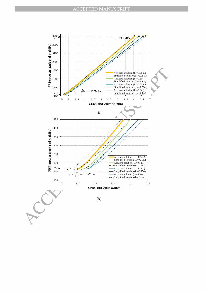
ACCEPTED MANUSCRIPT
ACCEPTED MANUSCRIP
T
1100
1500
1900
2300
2700
3100
3500
3900
1.5 2 2.5 3 3.5 4 4.5 5 5.5 6 6.5 7
FR
P s
tres
s at
crack
en
d σ
e(M
Pa)
Crack end width we(mm)
True Line(L=0.25au)Simplified Line(L=0.25au)系列3系列4系列5系列6系列7系列8
Accurate solution (L=0.25au)
Simplified solution(L=0.25au)
Accurate solution (L=0.5au)
Simplified solution (L=0.5au)
Accurate solution (L=0.75au)
Simplified solution (L=0.75au)
Accurate solution (L=0.9au)
Simplified solution (L=0.9au)
1165MPaλt
τσ
f
fb
r
bσ
MPa3900=r
Accurate solution (Lb=0.25au) Simplified solution(Lb=0.25au) Accurate solution (Lb=0.5au) Simplified solution (Lb=0.5au) Accurate solution (Lb=0.75au) Simplified solution (Lb=0.75au) Accurate solution (Lb=0.9au) Simplified solution (Lb=0.9au)
(a)
1100
1150
1200
1250
1300
1350
1400
1450
1.5 1.7 1.9 2.1 2.3 2.5
FR
P s
tres
s at
crack
en
d σ
e(M
Pa)
Crack end width we(mm)
True Line(L=0.25au)Simplified Line(L=0.25au)系列3系列4系列5系列6系列7系列8
Accurate solution (L=0.25au)
Simplified solution(L=0.25au)
Accurate solution (L=0.5au)
Simplified solution (L=0.5au)
Accurate solution (L=0.75au)
Simplified solution (L=0.75au)
Accurate solution (L=0.9au)
Simplified solution (L=0.9au)
1165MPaλt
τσ
f
fb
bσ
Accurate solution (Lb=0.25au) Simplified solution(Lb=0.25au) Accurate solution (Lb=0.5au) Simplified solution (Lb=0.5au) Accurate solution (Lb=0.75au) Simplified solution (Lb=0.75au) Accurate solution (Lb=0.9au) Simplified solution (Lb=0.9au)
(b)

ACCEPTED MANUSCRIPT
ACCEPTED MANUSCRIP
T
1100
1500
1900
2300
2700
3100
0 0.01 0.02 0.03 0.04 0.05 0.06 0.07 0.08 0.09 0.1 0.11 0.12
FR
P S
tres
s a
t cr
ack
en
d σ
e(M
Pa
)
Δwe (mm)
L=0.25au
L=0.5au
L=0.75au
L=0.9au
Lb=0.25au
Lb =0.5au
Lb =0.75au
Lb =0.9au
1165MPaλt
τσ
f
fb
bσ
(c)
Fig. 12. Comparison between simplified solution and accurate solution for σe -we
curves (, 300f eh mm, ' 30cf MPa, 230fE GPa, 0.11ft mm,
, 3900f ef MPa).

ACCEPTED MANUSCRIPT
ACCEPTED MANUSCRIP
T
0
10
20
30
40
50
60
70
80
0 2 4 6 8 10 12 14
Sh
ear
Fo
rce
(kN
)
Crack Width we(mm)
: FEM Solution(Lu's model)
: FEM Solution(Linear softening model)
: Analytical Solution
FEM solution (Lu et al. (2005) ‟s model)
FEM solution (Linear softening model)
Analytical solution
(a)
0
10
20
30
40
50
60
70
80
0 2 4 6 8 10 12 14
Sh
ear
Fo
rce
(kN
)
Crack Width we(mm)
: FEM Solution(Lu's model)
: FEM Solution(Linear softening model)
: Analytical Solution
FEM solution (Lu et al. (2005) ‟s model)
FEM solution (Linear softening model)
Analytical solution
(b)
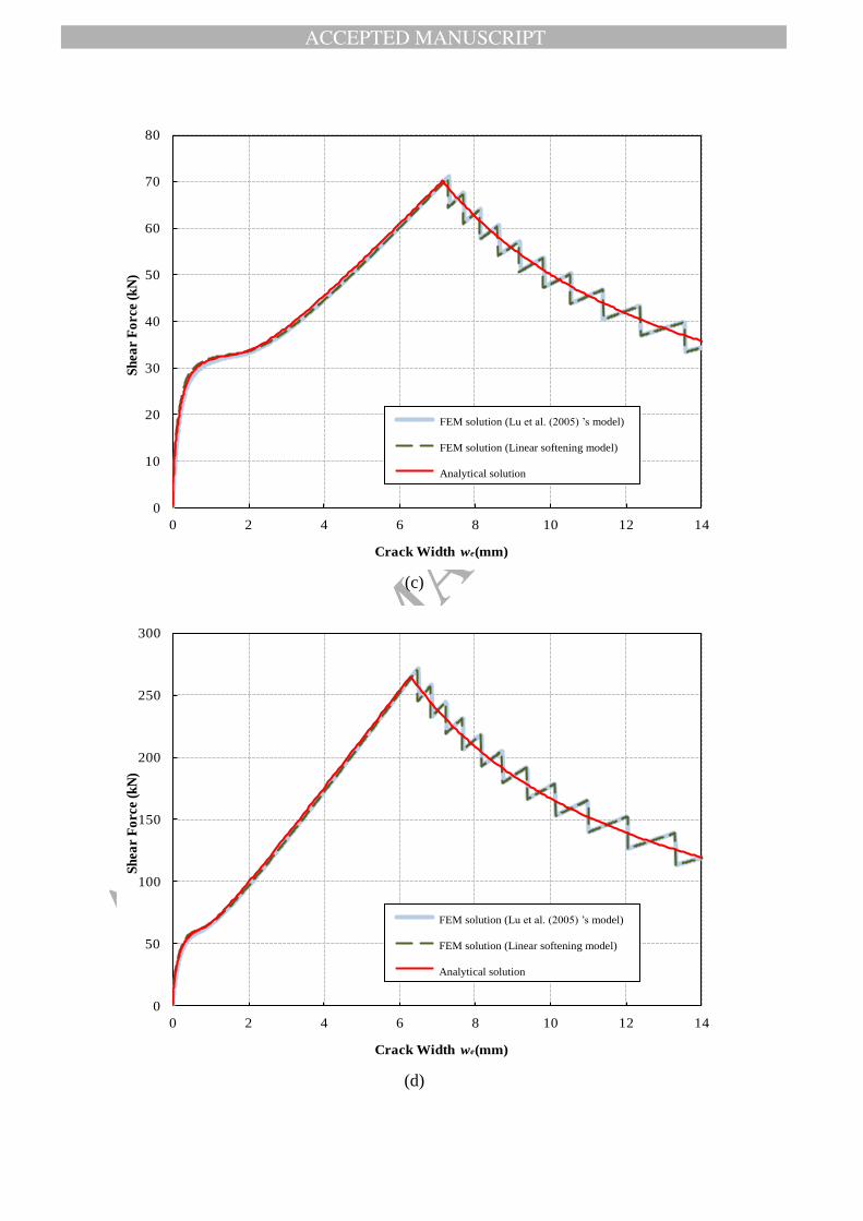
ACCEPTED MANUSCRIPT
ACCEPTED MANUSCRIP
T
0
10
20
30
40
50
60
70
80
0 2 4 6 8 10 12 14
Sh
ear
Fo
rce
(kN
)
Crack Width we(mm)
: FEM Solution(Lu's model)
: FEM Solution(Linear softening model)
: Analytical Solution
FEM solution (Lu et al. (2005) ‟s model)
FEM solution (Linear softening model)
Analytical solution
(c)
0
50
100
150
200
250
300
0 2 4 6 8 10 12 14
Sh
ear
Fo
rce
(kN
)
Crack Width we(mm)
: FEM Solution(Lu's model)
: FEM Solution(Linear softening model)
: Analytical Solution
FEM solution (Lu et al. (2005) ‟s model)
FEM solution (Linear softening model)
Analytical solution
(d)

ACCEPTED MANUSCRIPT
ACCEPTED MANUSCRIP
T
0
50
100
150
200
250
300
0 2 4 6 8 10 12 14
Sh
ear
Fo
rce
(kN
)
Crack Width we(mm)
: FEM Solution(Lu's model)
: FEM Solution(Linear softening model)
: Analytical Solution
FEM solution (Lu et al. (2005) ‟s model)
FEM solution (Linear softening model)
Analytical solution
(e)
0
50
100
150
200
250
300
0 2 4 6 8 10 12 14
Sh
ear
Fo
rce
(kN
)
Crack Width we(mm)
: FEM Solution(Lu's model)
: FEM Solution(Linear softening model)
: Analytical Solution
FEM solution (Lu et al. (2005) ‟s model)
FEM solution (Linear softening model)
Analytical solution
(f)

ACCEPTED MANUSCRIPT
ACCEPTED MANUSCRIP
T
0
100
200
300
400
500
600
0 2 4 6 8 10 12 14
Sh
ear
Fo
rce
(kN
)
Crack Width we(mm)
: FEM Solution(Lu's model)
: FEM Solution(Linear softening model)
: Analytical Solution
FEM solution (Lu et al. (2005) ‟s model)
FEM solution (Linear softening model)
Analytical solution
(g)
0
100
200
300
400
500
600
0 2 4 6 8 10 12 14
Sh
ear
Fo
rce
(kN
)
Crack Width we(mm)
: FEM Solution(Lu's model)
: FEM Solution(Linear softening model)
: Analytical Solution
FEM solution (Lu et al. (2005) ‟s model)
FEM solution (Linear softening model)
Analytical solution
(h)
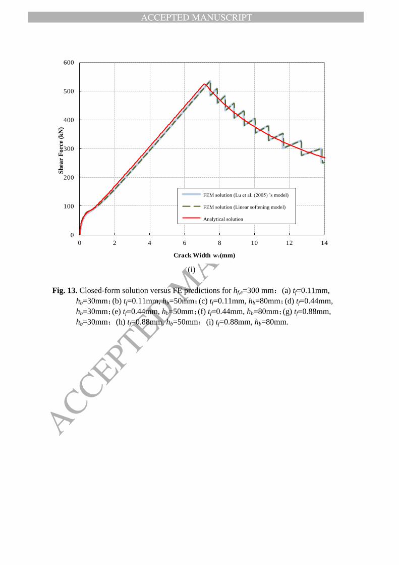
ACCEPTED MANUSCRIPT
ACCEPTED MANUSCRIP
T
0
100
200
300
400
500
600
0 2 4 6 8 10 12 14
Sh
ear
Fo
rce
(kN
)
Crack Width we(mm)
: FEM Solution(Lu's model)
: FEM Solution(Linear softening model)
: Analytical Solution
FEM solution (Lu et al. (2005) ‟s model)
FEM solution (Linear softening model)
Analytical solution
(i)
Fig. 13. Closed-form solution versus FE predictions for hf,e=300 mm:(a) tf=0.11mm,
hb=30mm;(b) tf=0.11mm, hb=50mm;(c) tf=0.11mm, hb=80mm;(d) tf=0.44mm,
hb=30mm;(e) tf=0.44mm, hb=50mm;(f) tf=0.44mm, hb=80mm;(g) tf=0.88mm,
hb=30mm;(h) tf=0.88mm, hb=50mm;(i) tf=0.88mm, hb=80mm.

ACCEPTED MANUSCRIPT
ACCEPTED MANUSCRIP
T
0
20
40
60
80
100
120
140
160
0 2 4 6 8 10 12 14 16 18 20
Sh
ear
Fo
rce
(kN
)
Crack Width we(mm)
: FEM Solution(Lu's model)
: FEM Solution(Linear softening model)
: Analytical Solution
FEM solution (Lu et al. (2005) ‟s model)
FEM solution (Linear softening model)
Analytical solution
(a)
0
20
40
60
80
100
120
140
160
0 2 4 6 8 10 12 14 16 18 20
Sh
ear
Fo
rce
(kN
)
Crack Width we(mm)
: FEM Solution(Lu's model)
: FEM Solution(Linear softening model)
: Analytical Solution
FEM solution (Lu et al. (2005) ‟s model)
FEM solution (Linear softening model)
Analytical solution
(b)

ACCEPTED MANUSCRIPT
ACCEPTED MANUSCRIP
T
0
20
40
60
80
100
120
140
160
0 2 4 6 8 10 12 14 16 18 20
Sh
ear
Fo
rce
(kN
)
Crack Width we(mm)
: FEM Solution(Lu's model)
: FEM Solution(Linear softening model)
: Analytical Solution
FEM solution (Lu et al. (2005) ‟s model)
FEM solution (Linear softening model)
Analytical solution
(c)
0
100
200
300
400
500
600
0 2 4 6 8 10 12 14 16 18 20
Sh
ear
Fo
rce
(kN
)
Crack Width we(mm)
: FEM Solution(Lu's model)
: FEM Solution(Linear softening model)
: Analytical Solution
FEM solution (Lu et al. (2005) ‟s model)
FEM solution (Linear softening model)
Analytical solution
(d)

ACCEPTED MANUSCRIPT
ACCEPTED MANUSCRIP
T
0
100
200
300
400
500
600
0 2 4 6 8 10 12 14 16 18 20
Sh
ear
Fo
rce
(kN
)
Crack Width we(mm)
: FEM Solution(Lu's model)
: FEM Solution(Linear softening model)
: Analytical Solution
FEM solution (Lu et al. (2005) ‟s model)
FEM solution (Linear softening model)
Analytical solution
(e)
0
100
200
300
400
500
600
0 2 4 6 8 10 12 14 16 18 20
Sh
ear
Fo
rce
(kN
)
Crack Width we(mm)
: FEM Solution(Lu's model)
: FEM Solution(Linear softening model)
: Analytical Solution
FEM solution (Lu et al. (2005) ‟s model)
FEM solution (Linear softening model)
Analytical solution
(f)

ACCEPTED MANUSCRIPT
ACCEPTED MANUSCRIP
T
FEM solution (Lu et al. (2005) ‟s model)
FEM solution (Linear softening model)
Analytical solution
(g)
FEM solution (Lu et al. (2005) ‟s model)
FEM solution (Linear softening model)
Analytical solution
(h)

ACCEPTED MANUSCRIPT
ACCEPTED MANUSCRIP
T
FEM solution (Lu et al. (2005) ‟s model)
FEM solution (Linear softening model)
Analytical solution
(i)
Fig. 14. Closed-form solution versus FE predictions for hf,e=600 mm:(a) tf=0.11mm,
hb=30mm;(b) tf=0.11mm, hb=50mm;(c) tf=0.11mm, hb=80mm;(d) tf=0.44mm,
hb=30mm;(e) tf=0.44mm, hb=50mm;(f) tf=0.44mm, hb=80mm;(g) tf=0.88mm,
hb=30mm;(h) tf=0.88mm, hb=50mm;(i) tf=0.88mm, hb=80mm.