full product line north america - cummins power … 938 750 850 680 qst30-g5 epa tier 2 hc6g pcc3201...
TRANSCRIPT
Full Product Line
North America
Fully Integrated, Reliable, Efficient
2 power.cummins.com
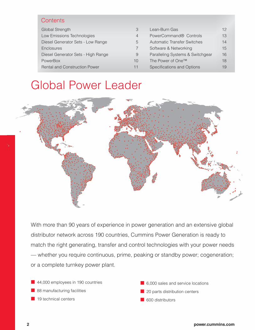
Global Power Leader
With more than 90 years of experience in power generation and an extensive global
distributor network across 190 countries, Cummins Power Generation is ready to
match the right generating, transfer and control technologies with your power needs
— whether you require continuous, prime, peaking or standby power; cogeneration;
or a complete turnkey power plant.
Contents
44,000 employees in 190 countries
88 manufacturing facilities
19 technical centers
6,000 sales and service locations
20 parts distribution centers
600 distributors
Global Strength 3
Low Emissions Technologies 4
Diesel Generator Sets - Low Range 5
Enclosures 7
Diesel Generator Sets - High Range 9
PowerBox 10
Rental and Construction Power 11
Lean-Burn Gas 12
PowerCommand® Controls 13
Automatic Transfer Switches 14
Software & Networking 15
Paralleling Systems & Switchgear 16
The Power of One™ 18
Specifications and Options 19
power.cummins.com 3
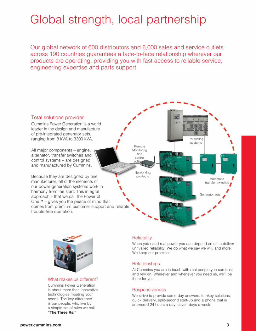
Remote
Monitoring
and
control
software
Networking
products
Paralleling
systems
Automatic
transfer switches
Generator sets
What makes us different?
Cummins Power Generation
is about more than innovative
technologies meeting your
needs. The key difference
is our people, who live by
a simple set of rules we call
“The Three Rs.”
Reliability
When you need real power you can depend on us to deliver
unrivalled reliability. We do what we say we will, and more.
We keep our promises.
Relationships
At Cummins you are in touch with real people you can trust
and rely on. Wherever and whenever you need us, we’ll be
there for you.
Responsiveness
We strive to provide same-day answers, turnkey solutions,
quick delivery, split-second start-up and a phone that is
answered 24 hours a day, seven days a week.
Total solutions provider
Cummins Power Generation is a world
leader in the design and manufacture
of pre-integrated generator sets,
ranging from 8 kVA to 3300 kVA.
All major components – engine,
alternator, transfer switches and
control systems – are designed
and manufactured by Cummins.
Because they are designed by one
manufacturer, all of the elements of
our power generation systems work in
harmony from the start. This integral
approach – that we call the Power of
One™ – gives you the peace of mind that
comes from premium customer support and reliable,
trouble-free operation.
Global strength, local partnership
Our global network of 600 distributors and 6,000 sales and service outlets
across 190 countries guarantees a face-to-face relationship wherever our
products are operating, providing you with fast access to reliable service,
engineering expertise and parts support.

Meeting the latest emissions requirements with our fully integrated generator
set applications.
We are committed to meeting or exceeding
clean air standards worldwide.
Leading the industry in advanced emissions solutions,
we ensure that our generator sets meet U.S. EPA and
EU emissions standards wherever possible.
Our strong history of emission leadership has enabled
us to develop our own emission solutions package
in accordance with EPA and EU regulations and
requirements.
Developing products for a cleaner tomorrow
Cummins Power Generation leads the industry in the
development of cleaner, quieter and more efficient
diesel-powered generator sets. We are committed to
meeting or exceeding all global air quality regulatory
standards for stationary and non-road diesel-engine
generator sets through 2017 and beyond. This protects
public health and conserves vital natural resources.
Low Emissions Technologies
“Clean” power creates powder
Snow Summit Ski Resort, Big Bear Lake, California
A PowerCommand® system provides 12 megawatts of
electricity to power air compressors, water pumps and fan
guns that make up the resort’s snowmaking equipment. The
2 MW diesel generators are designed to meet Southern
California’s strict air-quality requirements.
New technologies to reduce emissions
Since 1996 in the US (EPA) and 1999 in the EU when
emissions regulations for nonroad diesel engines
first went into effect, Cummins Power Generation
has developed technologies that reduce the primary
pollutants in the exhaust of a diesel generator set by
approximately 80 percent. Pollutants such as nitrogen
oxides (NOx), hydrocarbons (HC) and particulate
matter (PM) from diesel engines are precursors to
smog and ozone in many populated areas of the
world. All our emissions-reduction technologies are
accomplished through in-cylinder design improvements
and precise control of the combustion process.
4 power.cummins.com
Cummins Tier 4 Aftertreatment Systems
Cummins Power Generation has developed an EPA-certified
aftertreatment solution for our high-horsepower generators
with power nodes from 750 kW – 2750 kW, using a number of
exclusive features:
• Rapid Response Exhaust Preheaters
• Full compatibility with all Cummins generator control
systems
• Airless diesel emissions fl uid (DEF) injection
• Closed-loop NOx controller
• Diesel particulate fi lter (DPF)
• Selective catalytic reduction (SCR)
• Flexible, modular design

power.cummins.com 5
Diesel Generator Sets 106 kVA to 2500 kVA (50 Hz)
Integrated design and manufacturing combine to give you unequalled
reliability, power quality, rated performance and efficient operation.
Model NameStandby Rating Prime Rating
Engine Model Emissions Compliance
Standard Alternator
Standard Control
Sound Enclo-surekVA kWe kVA kWe
DGDB 106 85 100 80 6BT5.9-G6 - UC3D PCC2100 ••
DGDK 125 100 113 90 6BTA5.9-G3 - UC3E PCC2100 ••
DFEH 440 352 400 320 QSX15-G8 - HC5C PCC2100 ••
DFEJ 500 400 455 364 QSX15-G8 - HC5E PCC2100 ••
DFEK 550 440 500 400 QSX15-G8 - HC5E PCC2100 ••
Model NameStandby Rating
Prime Rating
DCC Rating
Continuous Rating Engine Model Emissions
ComplianceStandard Alternator
Standard Control
kVA kWe kVA kWe kVA kWe kVA kWe
DQGAN 1400 1120 1275 1020 1275 1020 1025 820 QSK50-G4 TA Luft 2g / EPA Tier 2 PI734B PC3.3
DQGAH 1540 1232 1400 1120 1400 1120 1125 900 QSK50-G4 TA Luft 2g / EPA Tier 2 PI734D PC3.3
DQGAK 1540 1232 1400 1120 1400 1120 1200 880 QSK50-G4UR - PI734D PC3.3
DQGAG 1700 1269 1540 1232 1540 1232 1250 1000 QSK50-G4 TA Luft 2g / EPA Tier 2 PI734D PC3.3
DQGAJ 1700 1360 1540 1232 1540 1232 1200 960 QSK50-G4UR - PI734F PC3.3
DQGAM 1825 1460 1650 1320 1650 1320 1425 1140 QSK50-G7 EPA Tier 2 PI734F PC3.3
DQKAH 2000 1600 1825 1460 1825 1460 1400 1120 QSK60-G11 TA Luft 2g / EPA Tier 2 PI734F PC3.3
DQKAG 2250 1800 2000 1600 2000 1600 1400 1120 QSK60-G11 TA Luft 2g / EPA Tier 2 PI734F PC3.3
DQKAJ 2500 2000 2000 1600 2250 1800 1650 1320 QSK60-G18 TA Luft 2g / EPA Tier 2 LVSI804S PC3.3
• Standard • • Option - Not Available

Diesel Generator Sets10 kW to 1000 kW (60 Hz)
6 power.cummins.com
Powered by heavy-duty Cummins engines, PowerCommand® diesel
generator sets are known for their fuel efficiency, responsive transient
performance and rugged reliability.
Model NameStandby Rating Prime Rating
Engine Model Emissions Compliance Standard Alternator Standard Control Sound EnclosurekVA kWe kVA kWe
DSKAA 12.5 10 11.4 9.1 D1703-M EPA Tier 3 YD0431 PC1.1 ••
DSKAB 18.8 15 17 13.6 D1703-M EPA Tier 3 YD0862 PC1.1 ••
DSKBA 25 20 22.8 18.2 V2203-M EPA Tier 3 YD0862 PC1.1 ••
DSKCA 31.3 25 28.4 22.7 V3300 EPA Tier 3 YD0862 PC1.1 ••
DGHCA 37.5 30 33.7 27 4BT3.3-G5 EPA Tier 3 UC2C PCC2100 ••
DGHCB 43.7 35 40 32 4BT3.3-G5 EPA Tier 3 UC2C PCC2100 ••
DSFAA 44 35 40 32 QSB5-G3 EPA Tier 3 UC2C PCC2100 ••
DGHCC 50 40 45 36 4BT3.3-G5 EPA Tier 3 UC2C PCC2100 ••
DSFAB 50 40 44 35 QSB5-G3 EPA Tier 3 UC2C PCC2100 ••
DGHDA 63 50 - - 4BT3.3-G7 EPA Tier 3 UC2C PCC2100 ••
DSFAC 63 50 56 45 QSB5-G3 EPA Tier 3 UC2D PCC2100 ••
DGHDB 75 60 - - 4BT3.3-G7 EPA Tier 3 UC2C PCC2100 ••
DSFAD 75 60 68 54 QSB5-G3 EPA Tier 3 UC2F PCC2100 ••
DSFAE 100 80 90 72 QSB5-G3 EPA Tier 3 UC2G PCC2100 ••
DGDB 125 100 113 90 6BTA5.9-G6 EPA Tier 1 UC3D PCC2100 ••DSGAA 125 100 113 90 QSB7-G5 EPA Tier 3 UC3D PC1.1 ••DSGAB 156 125 141 113 QSB7-G5 EPA Tier 3 UC3E PC1.1 ••DGDK 156 125 141 113 6BTA5.9-G3 EPA Tier 1 UC3E PCC2100 ••
DSGAC 188 150 169 135 QSB7-G5 EPA Tier 3 UC3F PC1.1 ••
DSGAD 219 175 200 160 QSB7-G5 EPA Tier 3 UC3H PC1.1 ••
DSGAE 250 200 225 180 QSB7-G5 EPA Tier 3 UC3H PC1.1 ••
DSHAD 288 230 263 210 QSL9-G2 EPA Tier 3 UCD3J PCC2100 ••
DQDAA 313 250 281 225 QSL9-G7 EPA Tier 3 HC4D PCC2100 ••
DQDAB 344 275 313 250 QSL9-G7 EPA Tier 3 HC4D PCC2100 ••
DQDAC 375 300 338 270 QSL9-G7 EPA Tier 3 HC4E PCC2100 ••
DQHAB 375 300 338 270 QSM11-G4 EPA Tier 3 HC4E PCC2100 ••
DFEG 438 350 400 320 QSX15-G9 EPA Tier 2 HC5C PCC2100 ••
DFEH 500 400 456 365 QSX15-G9 EPA Tier 2 HC5C PCC2100 ••
DFEJ 563 450 513 410 QSX15-G9 EPA Tier 2 HC5D PCC2100 ••
DFEK 625 500 569 455 QSX15-G9 EPA Tier 2 HC5E PCC2100 ••
DQPAA 750 600 681 545 QSK19-G8 EPA Tier 2 HC5F PC2.3 ••
DQCA 750 600 681 545 QSK23-G7 EPA Tier 2 HC6G PCC2100 ••
DQPAB 812 650 681 545 QSK19-G8 EPA Tier 2 HC6H PC2.3 ••
DQCB 938 750 850 680 QSK23-G7 EPA Tier 2 HC6G PCC2100 ••
DQFAE 938 750 850 680 QST30-G17 EPA Tier 4i/4F HC6G PCC3201 ••
DQFAA 938 750 850 680 QST30-G5 EPA Tier 2 HC6G PCC3201 ••
DQCC 1000 800 906 725 QSK23-G7 EPA Tier 2 HC6G PCC2100 ••
DQFAF 1000 800 906 725 QST30-G17 EPA Tier 4i/4F HC6G PCC3201 ••
DQFAB 1000 800 906 725 QST30-G5 EPA Tier 2 HC6G PCC3201 ••
DQFAG 1125 900 1023 818 QST30-G17 EPA Tier 4i/4F HC6H PCC3201 ••
DQFAC 1125 900 1023 818 QST30-G5 EPA Tier 2 HC6H PCC3201 ••
DQFAH 1250 1000 1125 900 QST30-G17 EPA Tier 4i/4F HC6K PCC3201 ••
DQFAD 1250 1000 1125 900 QST30-G5 EPA Tier 2 HC6K PCC3201 ••
• Standard • • Option - Not Available

Diesel Generator Sets1250 kW to 2750 kW (60 Hz)
power.cummins.com 7
Model NameStandby Rating Prime Rating DCC Rating Continuous
Rating Engine Model Emissions Compliance Standard Alternator Standard Control
kVA kWe kVA kWe kVA kWe kVA kWe
DQGAR 1563 1250 1419 1135 1419 1135 1250 1000 QSK50-G8 EPA Tier 4i/4F PI734B PC3.3
DQGAE 1563 1250 1419 1135 1419 1135 1250 1000 QSK50-G5 EPA Tier 2 PI734B PC3.3
DQGAS 1875 1500 1706 1365 1706 1365 1375 1100 QSK50-G8 EPA Tier 4i/4F PI734C PC3.3
DQGAF 1875 1500 1706 1365 1706 1365 1375 1100 QSK50-G5 EPA Tier 2 PI734C PC3.3
DQKAK 2188 1750 2000 1600 2000 1600 1813 1450 QSK60-G16 EPA Tier 4i/4F PI734C PC3.3
DQKAD 2188 1750 2000 1600 2000 1600 1813 1450 QSK60-G6 EPA Tier 2 PI734C PC3.3
DQKAL 2500 2000 2281 1825 2281 1825 2000 1600 QSK60-G16 EPA Tier 4i/4F PI734F PC3.3
DQKAE 2500 2000 2281 1825 2281 1825 2000 1600 QSK60-G6 EPA Tier 2 PI734F PC3.3
DQKAM 2813 2250 2281 1825 2500 2000 N/A N/A QSK60-G17 EPA Tier 4i/4F PI734G PC3.3
DQKAF 2813 2250 2281 1825 2500 2000 N/A N/A QSK60-G14 EPA Tier 2 PI734G PC3.3
DQLG 3125 2500 2844 2275 2844 2275 2500 2000 QSK78-G14 EPA Tier 4i/4F MVSI804S PC3.3
DQLE 3125 2500 2844 2275 2844 2275 2500 2000 QSK78-G12 EPA Tier 2 MVSI804S PC3.3
DQLC 3125 2500 2920 2336 2920 2336 2439 1951 QSK78-G6 - LVSI804R PCC3201
DQLH 3438 2750 3125 2500 3125 2500 2625 2100 QSK60-G14 EPA Tier 4i/4F MVSI804S PC3.3
DQLF 3438 2750 3125 2500 3125 2500 2625 2100 QSK78-G12 EPA Tier 2 MVSI804S PC3.3
DQLD 3438 2750 3125 2500 3125 2500 2700 2200 QSK78-G8 - LVSI804S PCC3201
• Standard • • Option - Not Available

8 power.cummins.com
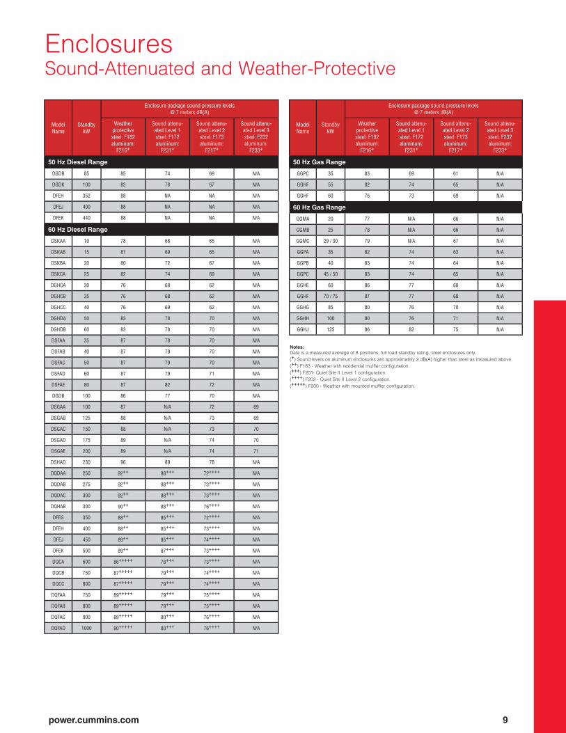
EnclosuresSound-Attenuated and Weather-Protective
Sound-attenuated and weather-protective enclosures from Cummins Power
Generation meet even the strictest sound requirements and provide optimum
protection from inclement weather.
• Three levels of sound attenuation
• Compact footprint, low-profile design
• Easy access to all major generator and engine control components for servicing
• Fully housed, enclosed exhaust silencer ensures safety and protects against rust
• All-steel construction with stainless-steel hardware offers durability
• Direct-mounted to a sub-base fuel tank or lifting base
• Prototype-tested to verify sound attenuation, cooling and ventilation system performance in extreme temperature
environments
• UL2200-listed
• IBC Seismic Certification option available
Acoustical Testing Center
The Acoustical Testing Center (ATC), located at the plant of Cummins
Power Generation in Fridley, Minnesota, U.S., is the largest engine
testing facility of its kind in the world.
• 23,000 sq. ft of total building area
• 13000 sq. ft of Hemi-Anechoic test area
• 5000 sq. ft build area
• Fully capable now of testing generator sets up to 3.3 MW
• Curved hemispherical roof – the preferred acoustical design
• Facility built following the Leadership in Energy and Environmental
Design (LEED) guidelines for green building design.
Fixed-air inlet
and outlet
louvers
Stainless-steel
hardware
Resists rust
Recessed, lockable doors
Provide easy service access
and protect internal equipment
Enclosed
exhaust
system
Ensures
safety
Cambered roof
Prevents water
accumulation12- and 14-gauge
steel construction
Ships assembled
on fuel tank or
lifting base
Choice of
vertical or
horizontal
discharge
Emergency stop
button (standard
on 600–1000 kW)
Non-hydroscopic
sound insulation
Rodent barriers
on inlet and outlet
Flexible oil
and coolant
drain lines with
interior valves
power.cummins.com 9
Model Name
Standby kW
Enclosure package sound pressure levels @ 7 meters dB(A)
Weather protective steel: F182aluminum:
F216+
Sound attenu-ated Level 1steel: F172aluminum:
F231+
Sound attenu-ated Level 2steel: F173aluminum:
F217+
Sound attenu-ated Level 3steel: F232aluminum:
F233+
50 Hz Diesel Range
DGDB 85 85 74 69 N/A
DGDK 100 83 76 67 N/A
DFEH 352 88 NA NA N/A
DFEJ 400 88 NA NA N/A
DFEK 440 88 NA NA N/A
60 Hz Diesel Range
DSKAA 10 78 68 65 N/A
DSKAB 15 81 69 65 N/A
DSKBA 20 80 72 67 N/A
DSKCA 25 82 74 69 N/A
DGHCA 30 76 68 62 N/A
DGHCB 35 76 68 62 N/A
DGHCC 40 76 69 62 N/A
DGHDA 50 83 78 70 N/A
DGHDB 60 83 78 70 N/A
DSFAA 35 87 78 70 N/A
DSFAB 40 87 79 70 N/A
DSFAC 50 87 79 70 N/A
DSFAD 60 87 79 71 N/A
DSFAE 80 87 82 72 N/A
DGDB 100 86 77 70 N/A
DSGAA 100 87 N/A 72 69
DSGAB 125 88 N/A 73 69
DSGAC 150 88 N/A 73 70
DSGAD 175 89 N/A 74 70
DSGAE 200 89 N/A 74 71
DSHAD 230 96 89 78 N/A
DQDAA 250 92++ 88+++ 72++++ N/A
DQDAB 275 92++ 88+++ 73++++ N/A
DQDAC 300 92++ 88+++ 73++++ N/A
DQHAB 300 90++ 88+++ 76++++ N/A
DFEG 350 88++ 85+++ 72++++ N/A
DFEH 400 88++ 85+++ 73++++ N/A
DFEJ 450 89++ 85+++ 74++++ N/A
DFEK 500 89++ 87+++ 73++++ N/A
DQCA 600 86+++++ 78+++ 73++++ N/A
DQCB 750 87+++++ 79+++ 74++++ N/A
DQCC 800 87+++++ 79+++ 74++++ N/A
DQFAA 750 89+++++ 79+++ 75++++ N/A
DQFAB 800 89+++++ 79+++ 75++++ N/A
DQFAC 900 89+++++ 80+++ 76++++ N/A
DQFAD 1000 90+++++ 80+++ 76++++ N/A
Notes:
Data is a measured average of 8 positions, full load standby rating, steel enclosures only.
(+) Sound levels on aluminum enclosures are approximately 2 dB(A) higher than steel as measured above.
(++) F183 - Weather with residential muffler configuration.
(+++) F201- Quiet Site II Level 1 configuration.
(++++) F202 - Quiet Site II Level 2 configuration.
(+++++) F200 - Weather with mounted muffler configuration.
Model Name
Standby kW
Enclosure package sound pressure levels @ 7 meters dB(A)
Weather protective steel: F182aluminum:
F216+
Sound attenu-ated Level 1steel: F172aluminum:
F231+
Sound attenu-ated Level 2steel: F173aluminum:
F217+
Sound attenu-ated Level 3steel: F232aluminum:
F233+
50 Hz Gas Range
GGPC 35 83 69 61 N/A
GGHF 55 82 74 65 N/A
GGHF 60 76 73 69 N/A
60 Hz Gas Range
GGMA 20 77 N/A 66 N/A
GGMB 25 78 N/A 66 N/A
GGMC 29 / 30 79 N/A 67 N/A
GGPA 35 82 74 63 N/A
GGPB 40 83 74 64 N/A
GGPC 45 / 50 83 74 65 N/A
GGHE 60 86 77 68 N/A
GGHF 70 / 75 87 77 68 N/A
GGHG 85 80 76 70 N/A
GGHH 100 80 76 71 N/A
GGHJ 125 86 82 75 N/A
EnclosuresSound-Attenuated and Weather-Protective

Spark-Ignited Generator Sets 20 kW to 895 kW (60 Hz)
Spark-ignited generator sets are a convenient choice for a variety of
emergency and standby applications, including healthcare offices and retail
businesses that require gaseous fuel options to meet local codes or fuel
containment and economic requirements. They are available with natural gas,
propane and dual fuel systems.
10 power.cummins.com
Installation and connection to the
fuel source lines are both basic and
convenient. As with our diesel generator
sets, a complete selection of voltages,
accessories, generator sets and control
options are available for customizing to
your specific needs.
Major features include:
• Multiple control system options,
including NFPA110 compliance
• Natural gas, propane or dual fuel
systems
• Weather-protective and sound-
attenuated enclosures (steel or
aluminum)
• Good motor-starting capability and fast
recovery from transient load changes
• Closed-loop fuel control system and
three-way catalyst to reduce emissions
(select models)
• U.S. EPA emissions compliance
GGMC
Note:
(+) EPA certified for stationary emergency applications.
• Standard • • Option - Not Available
Model Name Fuel Type
Standby Rating Engine
ModelEmissions
ComplianceStandard Alternator
Standard Control Sound Enclosure
kVA kWe
GGMA NG/Propane 25 20 GM i4 3L EPA+ YD0575 PCC1301 ••
GGMB NG/Propane 31 25 GM i4 3L EPA+ YD0700 PCC1301 ••
GGMC Natural Gas 36 29 GM V8 5L EPA+ YD1038 PCC1301 ••
GGMC Propane 38 30 GM V8 5L EPA+ YD1038 PCC1301 ••
GGPA NG/Propane 44 35 GM V8 5L EPA+ UC2C PCC2100 ••
GGPB NG/Propane 50 40 GM V8 5L EPA+ UC2D PCC2100 ••
GGPC Natural Gas 56 45 GM V8 5L EPA+ UC2D PCC2100 ••
GGPC Propane 63 50 GM V8 5L EPA+ UC2D PCC2100 ••
GGHE NG/Propane 75 60 Ford V10 6.8L EPA+ UC2F PCC2100 ••
GGHF Natural Gas 88 70 Ford V10 6.8L EPA+ UC2G PCC2100 ••
GGHF Propane 94 75 Ford V10 6.8L EPA+ UC2G PCC2100 ••
GGHG NG/Propane 106 85Ford V10T
6.8L EPA+ UC3C PCC2100 ••
GGHH NG/Propane 125 100Ford V10T
6.8L EPA+ UC3D PCC2100 ••
GGHJ NG/Propane 156 125Ford V10T
6.8L EPA+ UC3F PCC2100 ••
GFPA Propane 175 140 PSI 8.8L EPA SI NSPS+ UCI274 PCC1302 ••
GFPA Natural Gas 188 150 PSI 8.8L EPA SI NSPS+ UCI274 PCC1302 ••
GFBA CC Natural Gas 218 175 GTA855 EPA SI NSPS++ UCI274 PCC2100 ••
GFAC Natural Gas 218 175 GTA8.3 - UCI274 PCC2100 ••
GFBB CC Natural Gas 256 205 GTA855 EPA SI NSPS++ UCI274 PCC2100 ••
GFBC Cert Natural Gas 312 250 GTA855e EPA SI NSPS+ HC434 PCC2300 ••
GFBC Natural Gas 313 250 GTA855 - HC434 PCC2100 ••
GFEA CC Natural Gas 375 300 GTA19 EPA SI NSPS++ HC434 PCC2100 ••
GFEA Natural Gas 393 315 GTA19 - HC434 PCC2100 ••
GFEB Natural Gas 412 330 GTA19 - HC434 PCC2100 ••
GFEB Cert Natural Gas 437 350 KTA19 SLB EPA SI NSPS+ HC434 PCC2300 ••
GFGA CC Natural Gas 562 450 GTA28 EPA SI NSPS++ HC534 PCC2100 ••
GFGA Natural Gas 606 485 GTA28 - HC534 PCC2100 ••
GFJB CC Natural Gas 625 500 GTA38 EPA SI NSPS++ HC534 PCC2100 ••
GFJC CC Natural Gas 688 550 GTA38 EPA SI NSPS++ HC534 PCC2100 ••
GFJA Natural Gas 725 580 GTA38 - HC534 PCC2100 ••
GFLA CC Natural Gas 750 600 GTA50 EPA SI NSPS++ HC534 PCC2100 ••
GFJB Natural Gas 793 635 GTA38 - HC634 PCC2100 ••
GFLB CC Natural Gas 812 650 GTA50 EPA SI NSPS++ HC634 PCC2100 ••
GFJC Natural Gas 882 690 GTA38 - HC634 PCC2100 ••
GFLC CC Natural Gas 906 725 GTA50 EPA SI NSPS++ HC634 PCC2100 ••
GFLA Natural Gas 950 760 GTA50 - HC634 PCC2100 ••
GFLB Natural Gas 1018 815 GTA50 - HC634 PCC2100 ••
GFLC Natural Gas 1118 895 GTA50 - HC634 PCC2100 ••

power.cummins.com 11
Model Name60 Hz Prime Rating
Engine Model Emissions Compliance Standard Alternator Standard ControlkVA kWe
C60D6R 69 55 QSB5-G1 TPEM (EPA Tier 3) UCI224F PCC1302
C80D6R 90 72 QSB5-G2 TPEM (EPA Tier 3) UCI224G PCC1302
C100D6R 113 90 QSB5-G4 TPEM (EPA Tier 3) UCI274D PCC1302
C150D6R 169 135 QSB7-G3 TPEM (EPA Tier 3) UCI274F PCC1302
C150D6R 169 135 QSB7-G6 EPA Tier4i UCI274F PCC1302
C200D6R 225 180 QSB7-G5 TPEM (EPA Tier 3) UCI274J PCC1302
C200D6R 225 180 QSB7-G6 EPA Tier4i UCI274J PCC1302
C300D6R 338 270 QSM11-G4 TPEM (EPA Tier 3) HCI434E PCC1302
C500D6RG 569 455 QSX15-G9 TPEM (EPA Tier 2) HC5F PCC2100
C800D6RG 906 725 QSK23-G7 TPEM (EPA Tier 2) HCI634H PCC3201
C1000D6RG 1125 900 QST30-G5 TPEM (EPA Tier 2) HCI634K PCC3201
C1500D6RG 1688 1350 QSK50-G4 TPEM (EPA Tier 2) HCI634H PCC3201
C1600D6RG 1813 1450 QSK23-G7 X 2 TPEM (EPA Tier 2) PI734C PCC3201
C2000D6RG 2250 1800 QST30-G5 X 2 TPEM (EPA Tier 2) HCI634K PCC3201
Rental and Construction Power
The Cummins Power Generation rental range of generator sets have been
designed to provide a number of key features and benefits to the customer.
Exceptionally quiet, our rental generator sets are designed to
improve profitability for the owner. With more built features as
standard they provide easier maintenance and transportability,
as well as greater reliability.
Features:• External emergency stop button
• Canopies are compliant to the 2000/14/CE step 2006
and are suitable for the most demanding applications,
particularly in residential areas
• Single point lift up to 100 kVA or patented two point
recessed lift from 150 kVA and above to avoid roof
access and reduce the risk of fall
• For better operation, all packages are proposed in Prime
Power Rating
• Acoustic insulation helps reduce noise levels
• • Internal fill up helps prevent spillage into the
environment
• Fork-lift capability on all models up to 200 kVA
• Easy connection bus bar eliminates the risk of accidental
contact
• Four pole CB with earth leakage protection
• Lockable doors to help prevent unauthorised access
• Window allows visibility of the controller whilst doors are
closed
• Easy Serviceability:
• Large double access door
• Easy access to the fuel and oil fill up, drainage and filters
• Easy external access to the radiator compartment
Additional Features:• Dual frequency capability (except models fitted with
sockets)
• Remote start capability
• Pre-filter fuel/water separator
• Adjustable earth leakage
C250 D2R
C500 D2RC1250 D2R
* RFQ through Custom Applications Group (CAG)
12 power.cummins.com
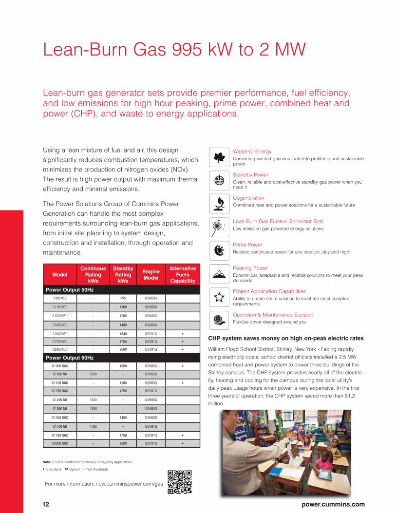
Lean-Burn Gas 995 kW to 2 MW
Lean-burn gas generator sets provide premier performance, fuel efficiency,
and low emissions for high hour peaking, prime power, combined heat and
power (CHP), and waste to energy applications.
Model
Continous
Rating
kWe
Standby
Rating
kWe
Engine
Model
Alternative
Fuels
Capability
Power Output 50Hz
C995N5C - 995 QSK60G
C1160N5C - 1160 QSK60G
C1200N5C - 1200 QSK60G
C1400N5C - 1400 QSK60G
C1540N5C - 1540 QSV91G •
C1750N5C - 1750 QSV91G •
C2000N5C - 2000 QSV91G •
Power Output 60Hz
C1000 N6C – 1000 QSK60G •
C1000 N6 1000 – QSK60G
C1100 N6C – 1100 QSK60G •
C1250 N6C – 1250 QSV91G
C1250 N6 1250 – QSK60G
C1350 N6 1350 – QSK60G
C1400 N6C – 1400 QSK60G
C1700 N6 1700 – QSV91G
C1750 N6C – 1750 QSV91G •
C2000 N6C – 2000 QSV91G •
Waste-to-Energy
Converting wasted gaseous fuels into profitable and sustainable
power
Standby Power
Clean, reliable and cost-effective standby gas power when you
need it
Cogeneration
Combined heat and power solutions for a sustainable future
Lean-Burn Gas Fuelled Generator Sets
Low emission gas powered energy solutions
Prime Power
Reliable continuous power for any location, day and night
Peaking Power
Economical, adaptable and reliable solutions to meet your peak
demands
Project Application Capabilities
Ability to create entire solution to meet the most complex
requeriments
Operation & Maintenance Support
Flexible cover designed around you
Using a lean mixture of fuel and air, this design
significantly reduces combustion temperatures, which
minimizes the production of nitrogen oxides (NOx).
The result is high power output with maximum thermal
efficiency and minimal emissions.
The Power Solutions Group of Cummins Power
Generation can handle the most complex
requirements surrounding lean-burn gas applications,
from initial site planning to system design,
construction and installation, through operation and
maintenance.
CHP system saves money on high on-peak electric rates
William Floyd School District, Shirley, New York - Facing rapidly
rising electricity costs, school district officials installed a 2.5 MW
combined heat and power system to power three buildings of the
Shirley campus. The CHP system provides nearly all of the electric-
ity, heating and cooling for the campus during the local utility’s
daily peak usage hours when power is very expensive. In the first
three years of operation, the CHP system saved more than $1.2
million.
For more information: now.cumminspower.com/gas
Note: (+) EPA certified for stationary emergency applications.
• Standard • • Option - Not Available
power.cummins.com 13
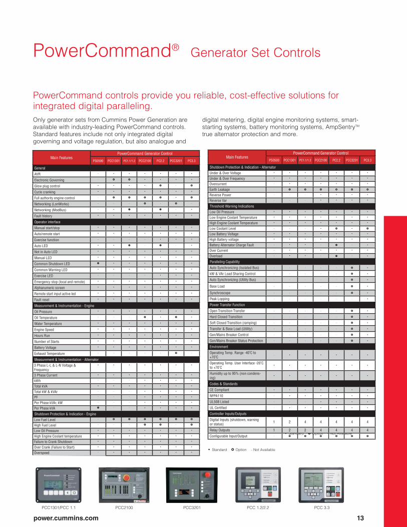
Only generator sets from Cummins Power Generation are
available with industry-leading PowerCommand controls.
Standard features include not only integrated digital
governing and voltage regulation, but also analogue and
digital metering, digital engine monitoring systems, smart-
starting systems, battery monitoring systems, AmpSentryTM
true alternator protection and more.
PowerCommand controls provide you reliable, cost-effective solutions for
integrated digital paralleling.
PowerCommand® Generator Set Controls
PCC2100PCC1301/PCC 1.1 PCC 3.3PCC 1.2/2.2PCC3201
Main FeaturesPowerCommand Generator Control
PS0500 PCC1301 PC1.1/1.2 PCC2100 PC2.2 PCC3201 PC3.3
General
AVR - • • • • • •
Electronic Governing - •• •• • • • •
Glow plug control • • • • •• - ••
Cycle cranking • • • • • • •
Full authority engine control - •• •• •• •• • ••
Networking (LonWorks) - - - •• - •• -
Networking (ModBus) - • •• - •• - •
Fault history • • • • • • •
Operator interface
Manual start/stop • • • • • • •
Auto/remote start • • • • • • •
Exercise function - - - - • • •
Auto LED • • •• - •• - •
Not in Auto LED • • • • • • •
Manual LED • • • • • • •
Common Shutdown LED • • • • • • • •
Common Warning LED • • • • • • •
Exercise LED - - - - • • •
Emergency stop (local and remote) • • • • • • •
Alphanumeric screen • • • • • • •
Remote start input active led • • • • • • •
Fault reset • • • • • • •
Measurement & Instrumentation - Engine
Oil Pressure • • • • • • •
Oil Temperature - - - •• • •• •
Water Temperature • • • • • • •
Engine Speed • • • • • • •
Hours Run • • • • • • •
Number of Starts • • • • • • •
Battery Voltage • • • • • • •
Exhaust Temperature - - - - - •• -
Measurement & Instrumentation - Alternator
3 Phase L-L & L-N Voltage & Frequency
• • • • • • •
3 Phase Current • • • • • • •
kWh - - - • • • •
Total kVA • • • • • • •
Total kW & kVAr - - - • • • •
PF - - - • • • •
Per Phase kVAr, kW - - - • • • •
Per Phase kVA •• - - • • • •
Shutdown Protection & Indication - Engine
Low Fuel Level - •• •• •• •• •• ••
High Fuel Level - - - •• •• - ••
Low Oil Pressure • • • • • • •
High Engine Coolant temperature • • • • • • •
Failure to Crank Shutdown • • • • • • •
Over Crank (Failure to Start) • • • • • • •
Overspeed - • • • • • •
• Standard • • Option - Not Available
Main FeaturesPowerCommand Generator Control
PS0500 PCC1301 PC1.1/1.2 PCC2100 PC2.2 PCC3201 PC3.3
Shutdown Protection & Indication - Alternator
Under & Over Voltage • • • • • • •
Under & Over Frequency • • • • • • •
Overcurrent - • • • • • •
Earth Leakage - •• •• •• •• •• ••
Reverse Power - - - • • • •
Reverse Var - - - • • • •
Threshold Warning Indications
Low Oil Pressure • • • • • • •
Low Engine Coolant Temperature • • • • • • •
High Engine Coolant Temperature • • • • • • •
Low Coolant Level - - - • •• • ••
Low Battery Voltage • • • • • • •
High Battery voltage • • • • • • •
Battery Alternator Charge Fault - • • - •• - •
Over Current - • • • • • •
Overload - • • - •• - •
Paralleling Capability
Auto Synchronizing (Isolated Bus) - - - - - •• •
kW & VAr Load Sharing Control - - - - - •• •
Auto Synchronizing (Utility Bus) - - - - - •• •
Base Load - - - - - •• •
Synchroscope - - - - - •• •
Peak Lopping - - - - - - •
Power Transfer Function
Open Transition Transfer - - - - - •• •
Hard Closed Transition - - - - - •• •
Soft Closed Transition (ramping) - - - - - •• •
Transfer & Base Load (Utility) - - - - - •• •
Gen/Mains Breaker Control - - - - - •• •
Gen/Mains Breaker Status Protection - - - - - •• •
Environment
Operating Temp. Range -40˚C to +70˚C
- • • • • • •
Operating Temp. User Interface -20˚C to +70˚C
• • • • • • •
Humidity up to 95% (non condens-ing)
• • • • • • •
Codes & Standards
CE Compliant • • • • • • •
NFPA110 - • • • • • •
UL508 Listed - - - • • • •
UL Certified - • • • • • •
Controller Inputs/Outputs
Digital Inputs (shutdown, warning or status) 1 2 4 4 4 4 4
Relay Outputs 1 2 2 4 4 4 4
Configurable Input/Output - •• •• •• •• •• ••
• Standard • • Option - Not Available
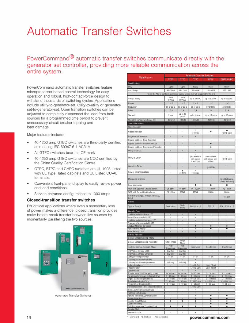
Automatic Transfer Switches
PowerCommand® automatic transfer switches communicate directly with the
generator set controller, providing more reliable communication across the
entire system.
PowerCommand automatic transfer switches feature
microprocessor-based control technology for easy
operation and robust, high-contact-force design to
withstand thousands of switching cycles. Applications
include utility-to-generator-set, utility-to-utility or generator-
set-to-generator-set. Open transition switches can be
adjusted to completely disconnect the load from both
sources for a programmed time period to prevent
unnecessary circuit breaker tripping and
load damage.
Major features include:
• 40-1250 amp GTEC switches are third-party certified
as meeting IEC 60947-6-1 AC31A
• All GTEC switches bear the CE mark
• 40-1250 amp GTEC switches are CCC certified by
the China Quality Certification Centre
• OTPC, BTPC and CHPC switches are UL 1008 Listed
with UL Type Rated cabinets and UL Listed CU-AL
terminals.
• Convenient front-panel display to easily review power
and load conditions
• Service entrance configurations to 1000 amps
Closed-transition transfer switches
For critical applications where even a momentary loss
of power makes a difference, closed transition provides
make-before-break transfer between live sources by
momentarily paralleling the two sources.
14 power.cummins.com
Automatic Transfer Switches
Main FeaturesAutomatic Transfer Switches
GTEC OTEC OTPC BTPC CHPC/OHPCSpecifications
Duty Light Light Heavy Heavy Heavy
Amp Range 40 - 2000 40 - 1200 40 - 4000 150 - 4000 125 - 800
(Select the ATS to suit the largest-sized supply (amps) that will be applied to the ATS)
Voltage Rating up to 480VAC
up to 600VAC up to 600VAC up to 600VAC up to 600VAC
Phases 1 or 3 1 or 3 1 or 3 1 or 3 1 or 3
Frequency 50 or 60Hz 50 or 60Hz 50 or 60Hz 50 or 60Hz 50 or 60Hz
Poles 2,3,4 3,4 3,4 3,4 2,3,4
Warranty 1 year up to 10 years up to 10 years up to 10 years up to 10 years
Operating Temperature Range (C°) -30 to 60 -40 to 60 -40 to 60 -40 to 60 -40 to 60
Switch Mechanism
Open Transition • • • • •
Closed Transition - - ••(>1000A)
••••
(CHPC only)
Programmed Transition • • • • -
Bypass Isolation - Open Transition - - - • -
Bypass Isolation - Closed Transition - - - •• -
Bypass Isolation - Programmed Transition - - - •• -
Utility-to-Genset • • • • •
Utility-to-Utility - -
•(not available with closed transition)
•(not available
with closed tran-sition)
•(OHPC only)
Genset-to-Genset • - ••
(<1000A)•
Service Entrance available -••
(≤1000A)•
(≤1000A) - -
Mechanical Interlock • • • •
•
(disabled during closed transition)
Load Monitoring - - •• •• ••
WCR with Specified Circuit Breakers 25-65kA 14-85kA 14 - 100kA 14 - 100kA 42 - 85kA
WCR with Current Limiting Fuses 26-120kA 200kA 200kA 200kA 200kA
Short-time ratings / 30-cycle rating (UL listed) - - - - 10-42kA
Control
Type of Control Basic micro Basic micro PCC L1 or L2 PCC L2 PCC L2/ L1 or L2
Operator Panel
Load Connected to Normal LED • • • • •
Normal Source Available LED • • • • •
Load Connected to Emergency LED • • • • •
Emergency Source Available LED • • • • •
Load AC Metering Bar Graph - - •• •• ••
Alphanumeric Display - - •• •• ••
Panel Security Lock - - • • •
Control Functions
3-phase Voltage Sensing - Utility • • • • •
3-phase Voltage Sensing - Generator Single Phase Single Phase
• • •
Electrical Isolation from AC - Mains High Impedance
High Impedance Transformer Transformer Transformer
O/U Voltage Sensing Utility U/V Only U/V Only • • •
O/U Voltage Sensing Generator U/V Only U/V Only • • •
Voltage Sensing Accuracy +/- 2% +/- 2% +/- 2% +/- 2% +/- 2%O/U Frequency Sensing Utility - - • • •
O/U Frequency Sensing Generator U/F Only U/F Only • • •
Voltage Imbalance - - Level 2 Cont Level 2 Cont •
Phase Rotation - - Level 2 Cont Level 2 Cont •
Loss of Phase - • • • •
Transfer Normal to Emergency (time) 0 - 300 secs 0 - 300 secs 0 -120 secs 0 -120 secs 0 -120 secsRe-transfer Emergency to Normal (time) 0 - 30 mins 0 - 30 mins 0 - 30 mins 0 - 30 mins 0 - 30 minsEngine Start Delay (adjustable) 0 - 10 sec 0 - 10 sec 0 - 120 secs 0 - 120 secs 0 - 120 secsTime Delay to Engine Stop 0 - 30 mins 0 - 30 mins 0 - 1800 secs 0 - 1800 secs 0 - 1800 secsProgrammed Transition (time) 0 - 10 sec 0 - 10 sec 0 - 60 secs 0 - 60 secs 0 - 60 secsFail to Disconnect Timer (closed transition) - - Level 2 Cont • •
Time & Date-Stamped Event Log - - • • •
Historical Data Display - - • • •
Remote Monitoring/Communication - - •• •• ••
System Data Display - - •• •• ••
Elevator Signal Module •• •• •• •• ••
Load Sequencing - - •• •• ••
Fully-Programmable Exerciser Clock •• •• •• •• ••
Exercise Clock • • • • •
Real-Time Clock - - • • •
• Standard • • Option - Not Available
power.cummins.com 15
Whether you’re using a desktop computer, a laptop or a
cell phone, PowerCommand remote monitoring systems
help you reduce power setup time, operation and
maintenance.
PowerCommand accessories for reliable web-
based monitoring
PowerCommand remote monitoring systems let you
monitor generator set and transfer switch functions via
the Internet. You can:
• Monitor remotely via wireless connection using
cellular or satellite communications
• Communicate via an Ethernet connection, phone line
or available wireless configuration
• Connect via an Internet browser on a remote PC
• Send alarms to cell phones, pagers or e-mail
addresses
• Display voltage and frequency of each source
• Monitor one or two generator sets and up to four
transfer switches
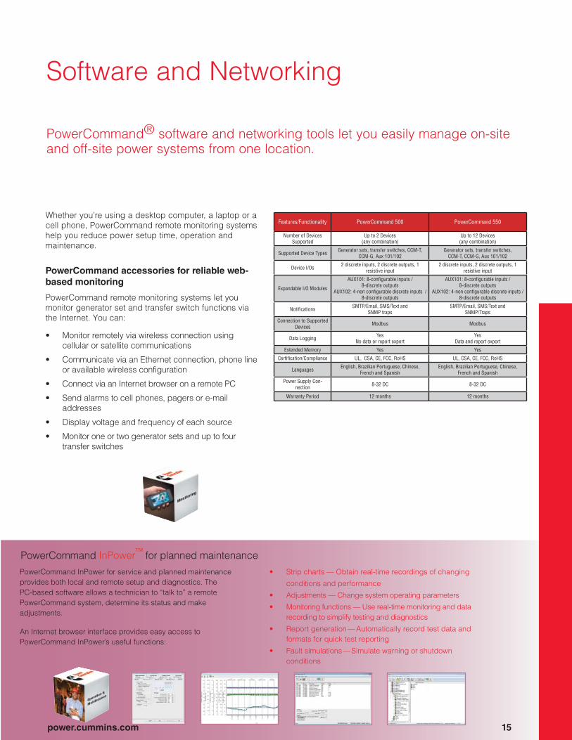
PowerCommand InPower for service and planned maintenance
provides both local and remote setup and diagnostics. The
PC-based software allows a technician to “talk to” a remote
PowerCommand system, determine its status and make
adjustments.
An Internet browser interface provides easy access to
PowerCommand InPower’s useful functions:
• Strip charts — Obtain real-time recordings of changing
conditions and performance
• Adjustments — Change system operating parameters
• Monitoring functions — Use real-time monitoring and data
recording to simplify testing and diagnostics
• Report generation — Automatically record test data and
formats for quick test reporting
• Fault simulations — Simulate warning or shutdown
conditions
PowerCommand InPower™
for planned maintenance
Software and Networking
PowerCommand® software and networking tools let you easily manage on-site
and off-site power systems from one location.
Features/Functionality PowerCommand 500 PowerCommand 550
Number of Devices Supported
Up to 2 Devices(any combination)
Up to 12 Devices(any combination)
Supported Device Types Generator sets, transfer switches, CCM-T, CCM-G, Aux 101/102
Generator sets, transfer switches, CCM-T, CCM-G, Aux 101/102
Device I/Os 2 discrete inputs, 2 discrete outputs, 1 resistive input
2 discrete inputs, 2 discrete outputs, 1 resistive input
Expandable I/O Modules
AUX101: 8-configurable inputs /8-discrete outputs
AUX102: 4-non configurable discrete inputs / 8-discrete outputs
AUX101: 8-configurable inputs /8-discrete outputs
AUX102: 4-non configurable discrete inputs / 8-discrete outputs
Notifications SMTP/Email, SMS/Text and SNMP traps
SMTP/Email, SMS/Text and SNMP/Traps
Connection to Supported Devices Modbus Modbus
Data Logging YesNo data or report export
YesData and report export
Extended Memory Yes Yes
Certification/Compliance UL, CSA, CE, FCC, RoHS UL, CSA, CE, FCC, RoHS
Languages English, Brazilian Portuguese, Chinese, French and Spanish
English, Brazilian Portuguese, Chinese, French and Spanish
Power Supply Con-nection 8-32 DC 8-32 DC
Warranty Period 12 months 12 months

Digital Paralleling Systems &
SwitchgearPowerCommand® paralleling systems are operated by DMC Digital Master
Controls that interface directly with PowerCommand controller generator set
optimizing performance and simplifying operation and service.
16 power.cummins.com
PowerCommand paralleling systems deliver the flexibility
demanded by your complex applications. We use common
control blocks with prototype-tested components. These
systems deliver the features and performance you require
and are supported by the industry’s only local paralleling
service organisation.
Demonstrated Reliability
Integrated paralleling in the generator set controls offers
fast synchronising. Any number of generator sets can be
synchronised in less than 15 seconds in most applications.
PowerCommand paralleling systems give you
demonstrated reliability:
• Industry-leading mean time before failure (MTBF) data
• Innovative failure mode effect analysis
• Prototype testing to validate system design
• Distributed logic designs that isolate issues by
eliminating single points of failure
Switchgear
DMC300DMC1500

power.cummins.com 17
Digital Paralleling Systems &
SwitchgearPowerCommand® paralleling systems are designed around dedicated-
purpose controllers that are prototype-tested for reliability and performance.
Main Features
DMC1000 DMC1500 DMC200 DMC300
Gen to Gen Paralleling
Utility Paralleling
Gen to Gen Paralleling
Utility Paralleling
Gen to Gen Paralleling
Utility Paralleling
Custom FeaturesCustom engineering available - - - - •• ••
Power SectionIntegrated low voltage switchgear •• •• •• •• •• ••
Integrated medium voltage switchgear •• •• •• •• •• ••
Outdoor switchgear enclosure •• •• •• •• •• ••
Protection relay •• •• •• •• •• ••
Switchgear station battery system •• •• •• •• •• ••
Neutral grounding resistor •• •• •• •• •• ••
Load bank •• •• •• •• •• ••
Genset Controller CompatibilityPowerCommand 3100 • • • • • •
PowerCommand 3200 • • • • • •
PowerCommand 3201 • • • • • •
PowerCommand 3.3 • • • • • •
System StartCommon system start directly to gens (bypasses DMC)
• •• - - •• ••
Common system start to genset based on DMC monitoring
- • • • •• ••
Enable/Disable automatic start signal when system is in manual
•• •• • • •• ••
Manual start and breaker open/close control of individual genset from HMI
- - •• •• • •
Genset ParallelingParallel up to 4 gensets • • • • • •
Parallel up to 8 gensets - - •• •• • •
Parallel more than 8 gensets - - - - •• ••
Load Demand
Fixed Sequence •
••(PC 3.3 required
in all Gensets)
•
••(PC 3.3 required
in all Gensets)
• •
Run Hour Sequence •
••(PC 3.3 required
in all Gensets)
•
••(PC 3.3 required
in all Gensets)
•• ••
Multiple Gen Busses - - - - •• ••
NE Function
Neutral Earth Device Control - - •• •• •• ••
Data communications, display, and alarming
Web Serving HMI Screens - - - - •• ••
Genset Summary data at the DMC - - •• •• • •
Real Time Trending - - • • • •
Historical Trending - - • • •• ••
Modbus RTU RS485 BMS Interface • • •• •• •• ••
Modbus RTU RS232 - - •• •• •• ••
Modbus TCP/IP over Ethernet BMS Interface - - •• •• •• ••
Remote monitoring with alarm paging and email - - - - •• ••Supervisory Monitoring Station for on-site/off-site power systems - - - - •• ••
System Annunciator(s) •• •• •• •• •• ••
Audible Alarm • • • • • •
Diagnostics • • • • • •
Operator Interface
HMI 211 Operator Interface • • - - - -15” Color Touch Screen - - • • • •
19” Color Touch Screen - - - - •• ••
42” Color Touch Screen - - - - •• ••
Customized systme HMI - - - - •• ••
Multiple HMI •• •• - - •• ••
• Standard • • Option - Not Available
Main Features
DMC1000 DMC1500 DMC200 DMC300
Gen to Gen Paralleling
Utility Paralleling
Gen to Gen Paralleling
Utility Paralleling
Gen to Gen Paralleling
Utility Paralleling
Redundant CPUHot Standby Redundant CPU and cabling - - - - •• ••ReportsAlarm History - - • • • •Plant Test Report (JACAHO) - - •• •• •• ••Custom Report - - - - •• ••Certification / ComplianceCE Mark • • • • • •UL891 •• • •• • •• •IEC •• • •• • •• •CSA •• • •• • •• •Seismic Zone 4 •• • •• • •• •OSHPD Certified •• • •• • •• •Load Add/ShedPriority Based - 6 Levels/6 Loads •• •• •• •• •• ••
Priority Based - 8 Levels/8 Loads •• •• •• •• •• ••
Priority Based - 10 Levels/10 Loads •• •• •• •• •• ••
Priority Based - 16 Levels/32 Loads •• •• •• •• •• ••
Capacity Based - single bus •• •• •• •• •• ••
Priority Based - multiple bus •• •• •• •• •• ••
Manual Load Add/Shed control •• •• •• •• •• ••
System TestWithout Load • • • • • •
With Load • • • • • •
System Scheduler (Exercise)Test • • • • •• ••
Extended Parallel - •• - •• - ••
Extended Utility Paralleling kW ControlGenset Bus % Level (Open Loop/Base Load) - •• - •• - •
Genset kW (Open Loop/Base Load) - - - - - •
Individual Genset kW (Open Loop/Base Load) - - - - - ••
Genset Bus kW (Closed Loop) - •• - •• - ••
Genset Bus kW with Utility Constraint (Closed Loop/Base Load with export limit)
- •• - •• - ••
Utiity Bus kW (Closed Loop/Peak Shave) - •• - •• - •
Extended Utility Paralleling kVAR ControlGen Bus % Level (Open Loop) - •• - •• - ••
Genset Bus Power Factor (Open Loop) - •• - •• - ••
Genset Bus kVAR (Closed Loop) - •• - •• - ••
Genset Bus Power Factor (Closed Loop) - •• - •• - ••
Utility Bus kVAR (Closed Loop)’ - •• - •• - ••
Utility Bus Power Factor (Closed Loop) - •• - •• - ••
Extended Paralleling ControlRemote start/stop - •• - •• - •
Facility load start/stop - •• - •• - ••
Power Transfer TransitionsOpen Transition - • - • • •
Hard Closed Transition <100 ms -••
(Transfer pair topol-ogy only)
-••
(Transfer pair topol-ogy only)
- ••
Hard Closed Transition non-ramping - • - • - •Soft Closed Transition - • - • - •
• Standard • • Option - Not Available

18 power.cummins.com
The Power of One™
The Power of One has two dimensions. First, it means a single manufacturer
of power generation products. And second, it means a single source for a
complete set of required services. These two dimensions combine to provide
a single source for complete power solutions.
Our Support Capabilities
• System design and application
engineering
• Power Suite™ 5.0 tool for sizing
and applying power generation
equipment
• Project management
• Product customization
• Total solution delivery
• Factory-trained, certified and highly
experienced technicians
• Planned maintenance availability
(PMA)
• Global distribution network with local
support
• Parts availability
• 24/7 emergency response system
• Remote and monitoring control

Emergency Standby Power (ESP):
Applicable for supplying power to varying electrical load for
the duration of power interruption of a reliable utility source.
Emergency Standby Power (ESP) is in accordance with ISO
8528. Fuel stop power in accordance with ISO 3046, AS
2789, DIN 6271 and BS 5514.
Prime Power (PRP):
Applicable for supplying power to varying electrical load
for unlimited hours. Prime Power (PRP) is in accordance
with ISO 8528. Ten percent overload capability is available
in accordance with ISO 3046, AS 2789, DIN 6271 and BS
5514.
Limited-Time Running Power (LTP):
Applicable for supplying power to a constant electrical load
for limited hours. Limited Time Running Power (LTP) is in
accordance with ISO 8528.
Base Load (Continuous) Power (COP):
Applicable for supplying power continuously to a constant
electrical load for unlimited hours. Continuous Power (COP)
in accordance with ISO 8528, ISO 3046, AS 2789, DIN 6271
and BS 5514.
Data Center Continuous (DCC):
Applicable for supplying power continuously to a constant
or varying electrical load for unlimited hours in a data center
application.
Specifications and Options
Every one of our generator sets is covered by a base warranty for round-the-year reliability. To further safeguard your
investment, we’ll extend that protection to cover every major component in our generator sets anywhere in the world.
You can choose from our suite of extended warranty coverage or packages that last for either two years, five years or ten
years to suit your specific needs before the original guarantee comes to an end.
For further details on all Extended Warranty options, please contact your local Cummins Power Generation distributor.
Extending your peace of mind with
our suite of Extended Warranty Options
power.cummins.com 19
Asia Pacific10 Toh Guan Road #07-01TT International TradeparkSingapore 608838
Phone 65 6417 2388Fax 65 6417 2399
BrazilRua Jati, 310, CumbicaGuarulhos, SP 07180-900, Brazil
Phone 55 11 2186 4195Fax 55 11 2186 4729
East AsiaNO. 2, Rongchang East Street Beijing Economic -Technological Development AreaBeijing 100176, P.R. China
Phone 86 10 5902 3000Fax 86 10 5902 3199
Europe, CIS, Middle East and AfricaManston Park Columbus Ave.Manston, Ramsgate, Kent CT12 5BF United Kingdom
Phone 44 1843 255000Fax 44 1843 255902
India35A/ 1/ 2, ErandawanaPune 411 038, India
Phone 91 20 3024 8600Fax 91 20 6602 8090
Latin America3350 Southwest 148th Ave.Suite 205, Miramar, FL 33027, USA
Phone 1 954 431 5511Fax 1 954 433 5797
MexicoEje 122 No. 200 Zona IndustrialSan Luis Potosí, S.L.P. 78395, Mexico
Phone 52 444 870 6700Fax 52 444 824 0082
North America1400 73rd Ave. NEMinneapolis, MN 55432, USA
Phone 1 763 574 5000Fax 1 763 574 5298
For more information contact your local
Cummins distributor. To find the one nearest
you visit www.cumminspower.com/en/locator
© 2013 Cummins Power Generation Inc. All rights reserved. Cummins Power Generation and Cummins are registered trademarks of Cummins Inc. PowerCommand® is a registered trademark of Cummins Power Generation. Our energy working for you.™ and The Power of One™ are trademarks of Cummins Power Generation.
All information contained within this document was correct at time of printing and may be subject to change.F-1186 (11/13)
Cummins Power Generation’s global operations
include 44,000 employees in 190 countries, with
88 manufacturing facilities, 6,000 sales and service
centers and 600 distributor locations.