full precast structure with unbonded · pdf fileaccount multiple interactions/systems....
TRANSCRIPT

http://www.iaeme.com/IJCIET/index.asp 843 [email protected]
International Journal of Civil Engineering and Technology (IJCIET) Volume 8, Issue 10, October 2017, pp. 843–865, Article ID: IJCIET_08_10_089
Available online at http://http://www.iaeme.com/ijciet/issues.asp?JType=IJCIET&VType=8&IType=10
ISSN Print: 0976-6308 and ISSN Online: 0976-6316
© IAEME Publication Scopus Indexed
FULL PRECAST STRUCTURE WITH
UNBONDED POSTTENSION PRESTRESSED
HYBRID FRAME STRUCTURES AT THE
TAMANSARI HIVE OFFICE PARK BUILDING,
JAKARTA, INDONESIA
Gambiro Suprapto
Research and Development
PT. Wijaya Karya Beton, Tbk., Jakarta, Indonesia
Almalik Husin, Widiasih, Andika Hadif Pratama, Iwan Ahmad Sofwan
The Tamansari Hive Office Park Building Project
PT. Wijaya Karya Beton, Tbk., Jakarta, Indonesia
Hari Nugraha Nurjaman
Persada Indonesia University, Jakarta,Indonesia
Riyanto Rivky
PT. Concedo Idea (Consultant), Jakarta, Indonesia
ABSTRACT
The need for high rise buildings in big cities like Jakarta is very urgent right now.
Requirements regarding the quality of concrete, speed and ease of implementation have
become demands. The Tamansari Hive Office Park is designed to meet these terms and
conditions. This building consists of 3 basement floors and upper structure of 12 stories.
The basement and shear wall structures are constructed from cast in place conventional
concrete. While the top structure uses precast components for floor plates, beams and
columns. This paper will describe the shape of beam, column and floor modeling in
precast system structures. Indonesia is one of areas affected by earthquake events. Thus,
earthquake load is a problem to be considered. Design of earthquake resistant buildings
follows the provisions in Building Requirements for Structural Concrete (ACI 318-11),
Indonesian Earthquake Resistance Design Procedures for Building and Non Building
Structures (SNI 1726 – 2002) and some related regulations, particularly design
regulations concerning precast buildings. The earthquake-resistant concept of this
building does not use the concept of strong columns weak beam as earthquake
absorbers, but uses the concept of self centering as described in the PRE cast Seismic
Structural System (PRESSS). This concept is implemented with Unbonded Post-
Gambiro Suprapto, Almalik Husin, Widiasih, Andika Hadif Pratama, Iwan Ahmad Sofwan, Hari
Nugraha Nurjaman and Riyanto Rivky
http://www.iaeme.com/IJCIET/index.asp 844 [email protected]
Tensioned Precast Concrete for Special Moment Frames that connect beams and
columns which meets the requirements of the ACI T1.2-03 Special Hybrid Moment
Frames Composed of Discretely Jointed Precast and Post-Tensioned Concrete
Members and ACI 550.3M-13 Design Specification for Unbonded Post-Tensioned
Precast Concrete Special Moment Frames Satisfying ACI 374.1. In addition, the beam
is also connected to a column with normal reinforcement as a weak connection.
Meanwhile the column to column connection uses grouted splice sleeve. The diaphragm
has important uses in the distribution of seismic forces, so that elements such as beams
and columns accept the forces according to their rigidity. Hollow core slabs are one-
way slab elements that are sheet-shaped and have a certain size. The elements must be
arranged into unity, in order to function as a rigid diaphragm. This paper explain the
using a method of construction without scaffolding for this project. This method will
speed up the installation of precast components and avoid work disruption at under the
floor. While the column to column connection using grouted splice sleeve.
Keyword: Precast, Self Centering, PRESSS, Unbonded Posttension Prestressed, Hollow
Core Slab, Unshoring, Diaphragm.
Cite this Article: Gambiro Suprapto, Almalik Husin, Widiasih, Andika Hadif Pratama,
Iwan Ahmad Sofwan, Hari Nugraha Nurjaman and Riyanto Rivky, Full Precast
Structure with Unbonded Posttension Prestressed Hybrid Frame Structures at The
Tamansari Hive office Park Building, Jakarta, Indonesia, International Journal of Civil
Engineering and Technology, 8(10), 2017, pp. 843–865.
http://www.iaeme.com/IJCIET/issues.asp?JType=IJCIET&VType=8&IType=10
1. INTRODUCTION
The Tamansari Hive Office Park is an office building located in Jakarta, Indonesia. This
building consists of 3 basement floors and 12 floors for the upper structures. The structures of
basement and shear walls are constructed from local casting conventional concrete. While its
upper structures use precast components for floor plates, beams and columns. The purpose of
using the pre-cast system is to speed up the implementation, and maintain quality. The narrow
location also becomes a consideration for the use of precast system. To accelerate the
implementation of this building, strategic steps are taken namely a) using Hollow Core Slab
with spans of ± 8 meters, b) not using scaffold on beams to get free space under floor. Beams
are seated on corbel which is expected to be strong when they gets vertical loads during
construction, c) columns to columns using large-tolerated grouted splice sleeve, making it easier
to mount columns, d) connection between columns is not positioned on the beam-column
connection to keep the quality of concrete in the area and avoid complexity during installing
due to tight reinforcement.
This earthquake-resisting structure system uses PRE-cast Seismic Structural System
(PRESSS) by applying Unbonded Post-Tensioned Precast Concrete Special Moment as
required on ACI 374.1-05 [4] and ACI 550.3M-13 {7]. This system uses the principle of self-
centering in which lateral deformation will be restored by unbonded post-tensioned prestressed.
To distribute lateral loads to the structures of portal and shear walls, diaphragm is required
on the floor. In the conventional structure, the diaphragm is a rigid massive floor. While the
structure with the HCS floor requires a special solution by combining the sheets of HCS into a
single unit.

Full Precast Structure with Unbonded Posttension Prestressed Hybrid Frame Structures at The
Tamansari Hive office Park Building, Jakarta, Indonesia
http://www.iaeme.com/IJCIET/index.asp 845 [email protected]
Figure 1 Tamansari Hive Office Park Building, Jakarta [17]
2. PRECAST STRUCTURE
2.1. Floor
The original floor design of this building is a local cast plate reinforced with secondary beams.
The plates are designed as two-way slabs. The shortages of this system are that it requires the
formwork and scaffolding to be installed continuously at least 3 floors and requires a long time
for concrete maintenance.
Figure 2 Conventional building plan [17]
Figure 2 shows the existence of secondary beams that can cause complexity in creating
formwork, especially when there are differences in the dimensions of crossing secondary
beams. To accelerate and facilitate the implementation, it needs another alternative. One of the
alternatives that can be applied is the use of Hollow Core Slab (HCS). HCS is installed at the
one same direction, so it is called one-way slab. By being installed at one direction, then workers
can focus more on two sides than two-way slabs that should focus on 4 sides, making it easier
to install HCS.
Gambiro Suprapto, Almalik Husin, Widiasih, Andika Hadif Pratama, Iwan Ahmad Sofwan, Hari
Nugraha Nurjaman and Riyanto Rivky
http://www.iaeme.com/IJCIET/index.asp 846 [email protected]
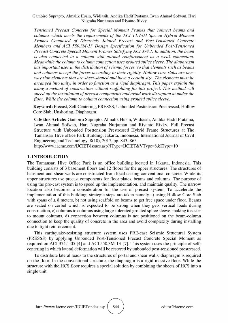
Figure 3 Building Plan with Hollow Core Slab [17]
HCS installation in one direction as shown in Figure 3. The mounting direction does not
always have to follow the pattern as the image in question. As for example, installed in
perpendicular direction to the previous pattern. Benefits obtained when using HCS namely it
does not require secondary beam to stiffen floor, does not require formwork and scaffolding,
does not require long time for concrete maintenance, can use long span so as to reduce
secondary beams, can function as Rigid-Diaphragm through interaction between wet joints and
HCS and beams; and long spans will increase productivity in HCS installation, thereby
shortening the construction implementation.
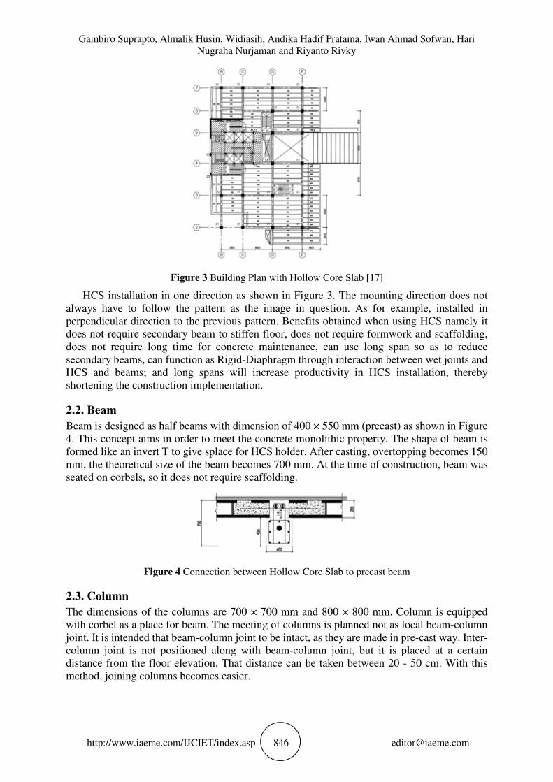
2.2. Beam
Beam is designed as half beams with dimension of 400 × 550 mm (precast) as shown in Figure
4. This concept aims in order to meet the concrete monolithic property. The shape of beam is
formed like an invert T to give splace for HCS holder. After casting, overtopping becomes 150
mm, the theoretical size of the beam becomes 700 mm. At the time of construction, beam was
seated on corbels, so it does not require scaffolding.
Figure 4 Connection between Hollow Core Slab to precast beam
2.3. Column
The dimensions of the columns are 700 × 700 mm and 800 × 800 mm. Column is equipped
with corbel as a place for beam. The meeting of columns is planned not as local beam-column
joint. It is intended that beam-column joint to be intact, as they are made in pre-cast way. Inter-
column joint is not positioned along with beam-column joint, but it is placed at a certain
distance from the floor elevation. That distance can be taken between 20 - 50 cm. With this
method, joining columns becomes easier.
Full Precast Structure with Unbonded Posttension Prestressed Hybrid Frame Structures at The
Tamansari Hive office Park Building, Jakarta, Indonesia
http://www.iaeme.com/IJCIET/index.asp 847 [email protected]
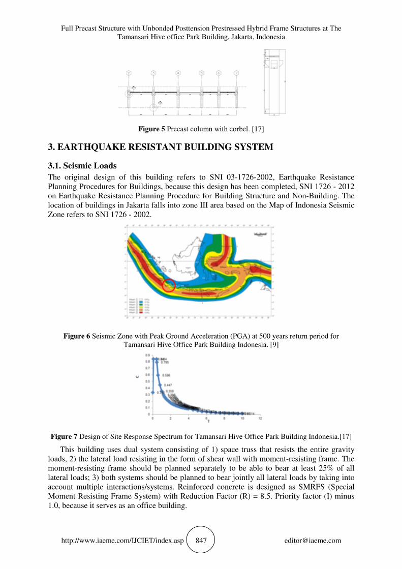
Figure 5 Precast column with corbel. [17]
3. EARTHQUAKE RESISTANT BUILDING SYSTEM
3.1. Seismic Loads
The original design of this building refers to SNI 03-1726-2002, Earthquake Resistance
Planning Procedures for Buildings, because this design has been completed, SNI 1726 - 2012
on Earthquake Resistance Planning Procedure for Building Structure and Non-Building. The
location of buildings in Jakarta falls into zone III area based on the Map of Indonesia Seismic
Zone refers to SNI 1726 - 2002.
Figure 6 Seismic Zone with Peak Ground Acceleration (PGA) at 500 years return period for
Tamansari Hive Office Park Building Indonesia. [9]
Figure 7 Design of Site Response Spectrum for Tamansari Hive Office Park Building Indonesia.[17]
This building uses dual system consisting of 1) space truss that resists the entire gravity
loads, 2) the lateral load resisting in the form of shear wall with moment-resisting frame. The
moment-resisting frame should be planned separately to be able to bear at least 25% of all
lateral loads; 3) both systems should be planned to bear jointly all lateral loads by taking into
account multiple interactions/systems. Reinforced concrete is designed as SMRFS (Special
Moment Resisting Frame System) with Reduction Factor (R) = 8.5. Priority factor (I) minus
1.0, because it serves as an office building.

Gambiro Suprapto, Almalik Husin, Widiasih, Andika Hadif Pratama, Iwan Ahmad Sofwan, Hari
Nugraha Nurjaman and Riyanto Rivky
http://www.iaeme.com/IJCIET/index.asp 848 [email protected]
To anticipate the eccentricity between the center of mass and the center of rotation as well
as the additional eccentricity, a) for 0 < e < 0.3 b, ed = 1.5 e + 0.05 b or ed = e - 0.05 b and
selected between the two of which has the most decisive influence, b) e > 0.3 b, ed = 1.33 e +
0.1 b or ed = 1.17e – 0.1 b or and is selected between the two which has the most decisive
influence. b is the largest horizontal measure of building structure plan on that level floor,
measured perpendicular to the direction of earthquake loading.
Figure 8a Comparison of shear forces at X-dir.[17]
Figure 8b. Comparison of Cumulative shear forces at X-dir.[17]
Figure 8c Comparison of shear forces at Y-dir.[17]
Full Precast Structure with Unbonded Posttension Prestressed Hybrid Frame Structures at The
Tamansari Hive office Park Building, Jakarta, Indonesia
http://www.iaeme.com/IJCIET/index.asp 849 [email protected]
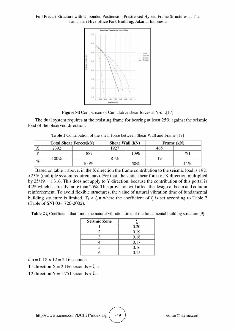
Figure 8d Comparison of Cumulative shear forces at Y-dir.[17]
The dual system requires at the resisting frame for bearing at least 25% against the seismic
load of the observed direction.
Table 1 Contribution of the shear force between Shear Wall and Frame [17]
Total Shear Forces(kN) Shear Wall (kN) Frame (kN)
X 2392 1927 465
Y 1887 1096 791
% 100% 81% 19
100% 58% 42%
Based on table 1 above, in the X direction the frame contribution to the seismic load is 19%
<25% (multiple system requirements). For that, the static shear force of X direction multiplied
by 25/19 = 1.316. This does not apply to Y direction, because the contribution of this portal is
42% which is already more than 25%. This provision will affect the design of beam and column
reinforcement. To avoid flexible structures, the value of natural vibration time of fundamental
building structure is limited. T1 < ζ.n where the coefficient of ζ is set according to Table 2
(Table of SNI 03-1726-2002).
Table 2 ζ Coefficient that limits the natural vibration time of the fundamental building structure [9]
Seismic Zone ζζζζ
1 0.20
2 0.19
3 0.18
4 0.17
5 0.16
6 0.15
ζ.n = 0.18 × 12 = 2.16 seconds
T1 direction X = 2.166 seconds ≈ ζ.n
T2 direction Y = 1.751 seconds < ζn

Gambiro Suprapto, Almalik Husin, Widiasih, Andika Hadif Pratama, Iwan Ahmad Sofwan, Hari
Nugraha Nurjaman and Riyanto Rivky
http://www.iaeme.com/IJCIET/index.asp 850 [email protected]
3.1. Service Performance Limits of X Direction
3.1.1. Service Performance Limits
The performance of service limit is determined based on the inter-level deviation. The
maximum limit of inter-level deviations is 0.03 H/8.5 or 30 mm, taken the smallest value. H is
the height between floors.[9]
3.1.2. Ultimate Performance Limits
The performance of ultimate limits is determined based on the inter-level deviation calculated
from the deviation of the building structure due to the nominal of seismic loading, multiplied
by a multiplier factor as follows: 1) for a regular building structure: ξ = 0,7 R, 2) for irregular
building structures: ξ =�.� �
��� ���� �, where R is the seismic reduction factor of building structure
and the Scale Factor is �.���
��≥ 1, where V1 is the nominal shear force as the first dynamic
response only and Vt is nominal of shear force obtained from the analysis of various spectrum
responses that have been performed. For the state of this building, with R = 8.5, then ξ = 0,7 ×
8.5 = 5.95.[9]
4. PRESSS SYSTEM
This building is designed with PRESSS concept. PRESSS is an earthquake resisting structure
system based on the principle of self-centering, a structure when gets lateral force will be
deformed to a certain distance and then will return to its original position. With self-centering,
seismic energy in the structure will be muffled. This self-centering can be achieved by
implementing unbonded post-tensioned mounted centrically on cross-section of beam and weak
reinforcing installed on the fiber as energy dissipater.
Figure 9a. Hysteresis Loop Rigid Frame
Figure 9b. Hysteresis loop Unbonded Post-Tensioned
Hysteresis loop at Unbonded Post-Tension are different to hysteresis loop with conventional
structure (rigid frame). Conventional moment resisting frames are designed with so-called
strong-column weak-beam criteria to dissipate seismic energy by forming plastic hinges at the
beam ends and at the base of the first story columns to form a global beam-sway mechanism

Full Precast Structure with Unbonded Posttension Prestressed Hybrid Frame Structures at The
Tamansari Hive office Park Building, Jakarta, Indonesia
http://www.iaeme.com/IJCIET/index.asp 851 [email protected]
(Figure 9a.). Although the structure is expected to behave in a ductile manner and dissipate a
significant quantity of seismic energy, there may be significant inelastic residual deformation.
While on the Unbonded Post-Tensioned, structure is capable of deforming to form graphs
such as butterflies (Figure 9b). At 0% drift, frame does not lose its ability. The greater the force
at 0% drift, the structure has the ability to absorb seismic energy. Self-centering concrete
moment frames consist of concrete beams and columns horizontally post-tensioned together so
that a gap can open at the beam-column interface when subjected to a specific applied moment.
Energy dissipation is supplied at the beam-to-column joint through a variety of mechanisms
such as unbonded mild reinforcing steel, friction damping elements and other devices.
Self-centering seismic lateral force resisting systems are capable of fully re-centering when
the lateral forces are removed (herein referred to as full self-centering), eliminating residual
drift. The flag-shaped hysteresis demonstrates self-centering ability since the displacement
returns to negligible values when the lateral forces are removed; however, the system should
be proportioned such that this self-centering can occur. (Figure 9b).
Gambiro Suprapto, Almalik Husin, Widiasih, Andika Hadif Pratama, Iwan Ahmad Sofwan, Hari
Nugraha Nurjaman and Riyanto Rivky
http://www.iaeme.com/IJCIET/index.asp 852 [email protected]
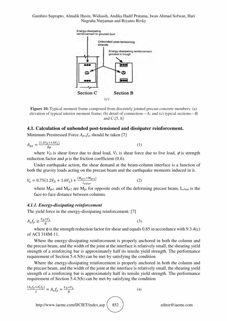
Figure 10. Typical moment frame composed from discretely jointed precast concrete members: (a)
elevation of typical interior moment frame; (b) detail of connection—A; and (c) typical sections—B
and C.[5, 8]
4.1. Calculation of unbonded post-tensioned and dissipater reinforcement.
Minimum Prestressed Force Aps.fse should be taken [7]
��� =(�.�����.���)
∅" (1)
where VD is shear force due to dead load, VL is shear force due to live load, φ is strength
reduction factor and µ is the friction coefficient (0.6).
Under earthquake action, the shear demand at the beam-column interface is a function of
both the gravity loads acting on the precast beam and the earthquake moments induced in it.
#$ = 0.75(1.2#) + 1.6#,) +(-./��-./0)
,1234/ (2)
where Mpr1 and Mpr2 are Mpr for opposite ends of the deforming precast beam, Lclear is the
face-to-face distance between columns.
4.1.1. Energy-dissipating reinforcement
The yield force in the energy-dissipating reinforcement: [7]
��56 ≥�����
∅ (3)
where φ is the strength reduction factor for shear and equals 0.85 in accordance with 9.3.4(c)
of ACI 318M-11.
Where the energy-dissipating reinforcement is properly anchored in both the column and
the precast beam, and the width of the joint at the interface is relatively small, the shearing yield
strength of a reinforcing bar is approximately half its tensile yield strength. The performance
requirement of Section 5.4.5(b) can be met by satisfying the condition
(789:�78; 9:)
�= ��56 =
�����
∅ (4)
Full Precast Structure with Unbonded Posttension Prestressed Hybrid Frame Structures at The
Tamansari Hive office Park Building, Jakarta, Indonesia
http://www.iaeme.com/IJCIET/index.asp 853 [email protected]
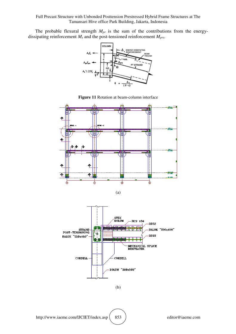
The probable flexural strength Mpr is the sum of the contributions from the energy-
dissipating reinforcement Ms and the post-tensioned reinforcement Mprs.
Figure 11 Rotation at beam-column interface
(a)
(b)
Gambiro Suprapto, Almalik Husin, Widiasih, Andika Hadif Pratama, Iwan Ahmad Sofwan, Hari
Nugraha Nurjaman and Riyanto Rivky
http://www.iaeme.com/IJCIET/index.asp 854 [email protected]
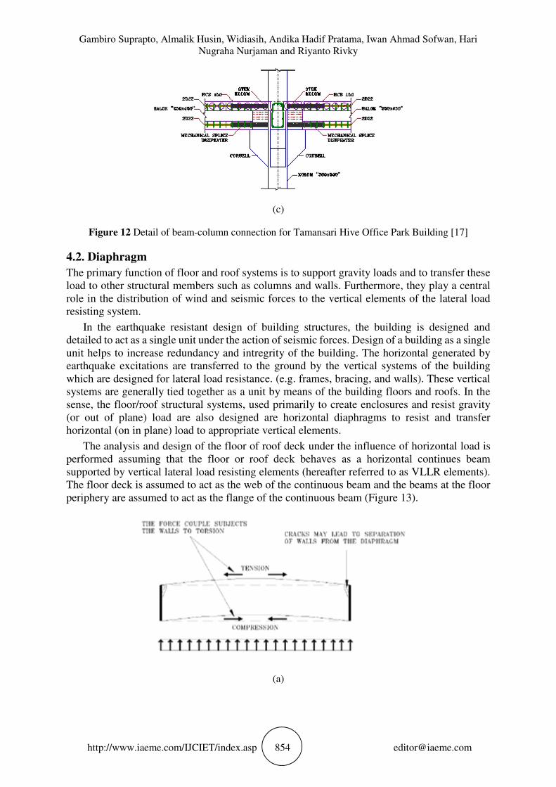
(c)
Figure 12 Detail of beam-column connection for Tamansari Hive Office Park Building [17]
4.2. Diaphragm
The primary function of floor and roof systems is to support gravity loads and to transfer these
load to other structural members such as columns and walls. Furthermore, they play a central
role in the distribution of wind and seismic forces to the vertical elements of the lateral load
resisting system.
In the earthquake resistant design of building structures, the building is designed and
detailed to act as a single unit under the action of seismic forces. Design of a building as a single
unit helps to increase redundancy and intregrity of the building. The horizontal generated by
earthquake excitations are transferred to the ground by the vertical systems of the building
which are designed for lateral load resistance. (e.g. frames, bracing, and walls). These vertical
systems are generally tied together as a unit by means of the building floors and roofs. In the
sense, the floor/roof structural systems, used primarily to create enclosures and resist gravity
(or out of plane) load are also designed are horizontal diaphragms to resist and transfer
horizontal (on in plane) load to appropriate vertical elements.
The analysis and design of the floor of roof deck under the influence of horizontal load is
performed assuming that the floor or roof deck behaves as a horizontal continues beam
supported by vertical lateral load resisting elements (hereafter referred to as VLLR elements).
The floor deck is assumed to act as the web of the continuous beam and the beams at the floor
periphery are assumed to act as the flange of the continuous beam (Figure 13).
(a)
Full Precast Structure with Unbonded Posttension Prestressed Hybrid Frame Structures at The
Tamansari Hive office Park Building, Jakarta, Indonesia
http://www.iaeme.com/IJCIET/index.asp 855 [email protected]
(b)
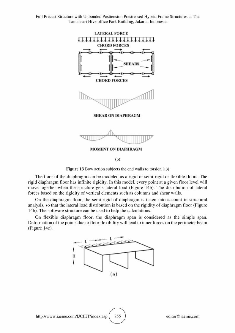
Figure 13 Bow action subjects the end walls to torsion.[13]
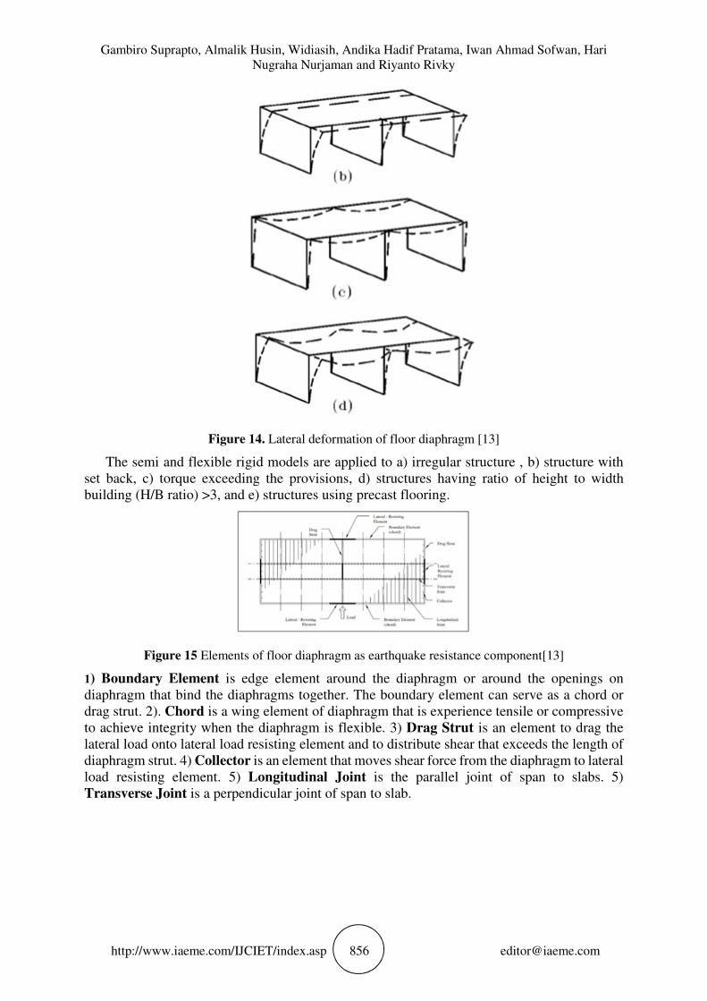
The floor of the diaphragm can be modeled as a rigid or semi-rigid or flexible floors. The
rigid diaphragm floor has infinite rigidity. In this model, every point at a given floor level will
move together when the structure gets lateral load (Figure 14b). The distribution of lateral
forces based on the rigidity of vertical elements such as columns and shear walls.
On the diaphragm floor, the semi-rigid of diaphragm is taken into account in structural
analysis, so that the lateral load distribution is based on the rigidity of diaphragm floor (Figure
14b). The software structure can be used to help the calculations.
On flexible diaphragm floor, the diaphragm span is considered as the simple span.
Deformation of the points due to floor flexibility will lead to inner forces on the perimeter beam
(Figure 14c).
Gambiro Suprapto, Almalik Husin, Widiasih, Andika Hadif Pratama, Iwan Ahmad Sofwan, Hari
Nugraha Nurjaman and Riyanto Rivky
http://www.iaeme.com/IJCIET/index.asp 856 [email protected]
Figure 14. Lateral deformation of floor diaphragm [13]
The semi and flexible rigid models are applied to a) irregular structure , b) structure with
set back, c) torque exceeding the provisions, d) structures having ratio of height to width
building (H/B ratio) >3, and e) structures using precast flooring.
Figure 15 Elements of floor diaphragm as earthquake resistance component[13]
1) Boundary Element is edge element around the diaphragm or around the openings on
diaphragm that bind the diaphragms together. The boundary element can serve as a chord or
drag strut. 2). Chord is a wing element of diaphragm that is experience tensile or compressive
to achieve integrity when the diaphragm is flexible. 3) Drag Strut is an element to drag the
lateral load onto lateral load resisting element and to distribute shear that exceeds the length of
diaphragm strut. 4) Collector is an element that moves shear force from the diaphragm to lateral
load resisting element. 5) Longitudinal Joint is the parallel joint of span to slabs. 5)
Transverse Joint is a perpendicular joint of span to slab.

Full Precast Structure with Unbonded Posttension Prestressed Hybrid Frame Structures at The
Tamansari Hive office Park Building, Jakarta, Indonesia
http://www.iaeme.com/IJCIET/index.asp 857 [email protected]

Gambiro Suprapto, Almalik Husin, Widiasih, Andika Hadif Pratama, Iwan Ahmad Sofwan, Hari
Nugraha Nurjaman and Riyanto Rivky
http://www.iaeme.com/IJCIET/index.asp 858 [email protected]
Figure 15 The parts of floor diaphragm [17]
4.2.1. Diaphragm Design Force [9, 10, 12]
The floor and roof diaphragms should be designed to bear the seismic force designed from
structural analysis based on the equation below:
<�= =∑ �?
@?AB
∑ C.B@?AB
D�= (6a)
where Fpx is a diaphragm design style, Fi is design force applied at i level, wi is a tributary
of weights up to i level and wpx is the tributary weight up to diaphragm at x level.
The forces in (6a) equation cannot be less than:
<�= = 0.2E)�FG�= (6b)
and cannot be exceeded
<�= = 0.4E)�FG�= (6c)
Longitudinal Joints [13]
Grounded keyways between slabs that have capacity to divert longitudinal shear forces from
one slab to another. Taking into account the shear stress of 80 psi (0.55 MPa), then the strength
of the elongated shear threshold is:
φVn = φ(0.08)hn. l (kips) (7a)
φVn = φ(0.55)hn. l (N) (7b)
where hn is the net height of grout key (in inch or mm), l is the lenght of grout key joint (in
inch or mm) and φ is taken by 0.85.

Full Precast Structure with Unbonded Posttension Prestressed Hybrid Frame Structures at The
Tamansari Hive office Park Building, Jakarta, Indonesia
http://www.iaeme.com/IJCIET/index.asp 859 [email protected]
If grout strength is exceeded, or ductility is required, longitudinal joint reinforcement is
installed (Figures 16a and 16b). Longitudinal reinforcement is determined by the formula:
�I9 =�J
∅9:" (8)
where Vu = factored applied shear
Figure 16a. Shear friction steel in butt joint [13]
Figure 16b. Alternate longitudinal shear connections [13]
4.2.3. Transverse Joints
The functions of transverse joints are a) Shear reinforcement for longitudinal joints, b) working
forward the axial tensile or compressive forces that carry loads on the diaphragm to the lateral
load resisting element, c) as a chord rod where tensile strength due to flexure is retained, d)
separating the horizontal beam body where horizontal shear must be transferred to maintain the
height of the composite diaphragm.
The tensile force on the chord is borne by reinforcement which gives bending strength to
the diaphragm.
Gambiro Suprapto, Almalik Husin, Widiasih, Andika Hadif Pratama, Iwan Ahmad Sofwan, Hari
Nugraha Nurjaman and Riyanto Rivky
http://www.iaeme.com/IJCIET/index.asp 860 [email protected]
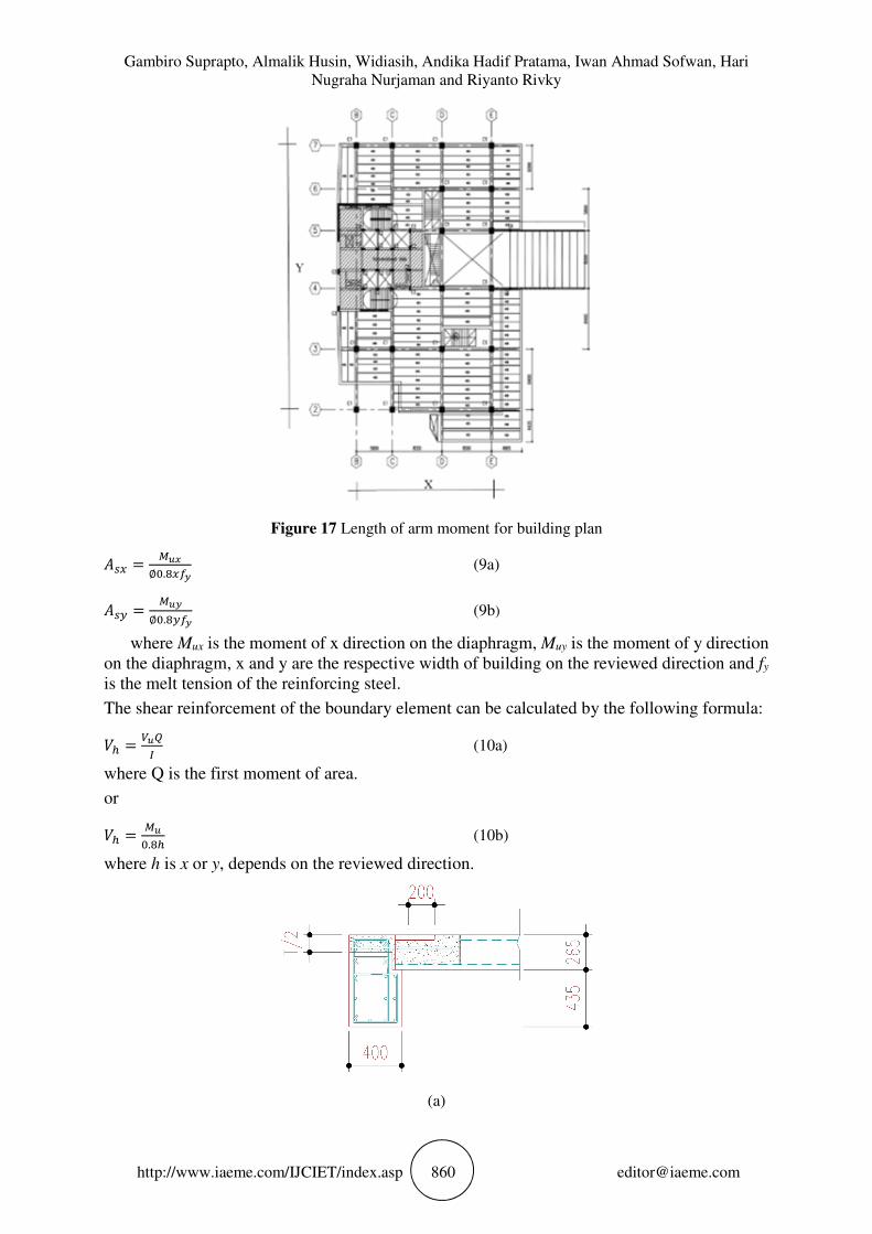
Figure 17 Length of arm moment for building plan
��= =-JB
∅�.�=9: (9a)
��6 =-J:
∅�.�69: (9b)
where Mux is the moment of x direction on the diaphragm, Muy is the moment of y direction
on the diaphragm, x and y are the respective width of building on the reviewed direction and fy
is the melt tension of the reinforcing steel.
The shear reinforcement of the boundary element can be calculated by the following formula:
#K =�JL
M (10a)
where Q is the first moment of area.
or
#K =-J
�.�K (10b)
where h is x or y, depends on the reviewed direction.
(a)
Full Precast Structure with Unbonded Posttension Prestressed Hybrid Frame Structures at The
Tamansari Hive office Park Building, Jakarta, Indonesia
http://www.iaeme.com/IJCIET/index.asp 861 [email protected]
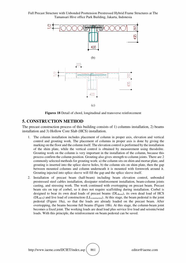
(b)
(c)
Figures 18 Detail of chord, longitudinal and transverse reinforcement
5. CONSTRUCTION METHOD
The precast construction process of this building consists of 1) columns installation, 2) beams
installation and 3) Hollow Core Slab (HCS) installation.
1. The column installation includes placement of column in proper axis, elevation and vertical
control and grouting work. The placement of columns in proper axis is done by giving the
marking on the floor and the column itself. The elevation control is performed by the installation
of the shim plate, while the vertical control is obtained by measurement using theodolite.
Grouting work on the column is very important in the installation of the column, because this
process confirm the column position. Grouting also gives strength to column joints. There are 2
commonly selected methods for grouting work: a) the column sits on shim and mortar plate, and
grouting is inserted into the splice sleeve holes, b) the column sits on shim plate, then the gap
between mounted columns and column underneath it is mounted with formwork around it.
Grouting injected into splice sleeve will fill the gap and the splice sleeve itself.
2. Installation of precast beam (half-beam) including beam elevation control, unbonded
prestressed steel cables installation, dissipater reinforcement installation, beam-column joints
casting, and stressing work. The work continued with overtopping on precast beam. Precast
beam sits on top of corbel, so it does not require scaffolding during installation. Corbel is
designed to bear its own dead loads of precast beams (DLBeam), its own dead load of HCS
(DLHCS) and live load of construction (LLconstruction). At this stage, the beam pedestal is the joint
pedestal (Figure 18a), so that the loads are already loaded on the precast beam. After
overtopping, the beams become full beams (Figure 18b). At this stage, the column-beam joint
becomes a fixed joint. The working loads are dead load plus service live load and seismic/wind
loads. With this principle, the reinforcement on beam pedestal can be saved.
Gambiro Suprapto, Almalik Husin, Widiasih, Andika Hadif Pratama, Iwan Ahmad Sofwan, Hari
Nugraha Nurjaman and Riyanto Rivky
http://www.iaeme.com/IJCIET/index.asp 862 [email protected]
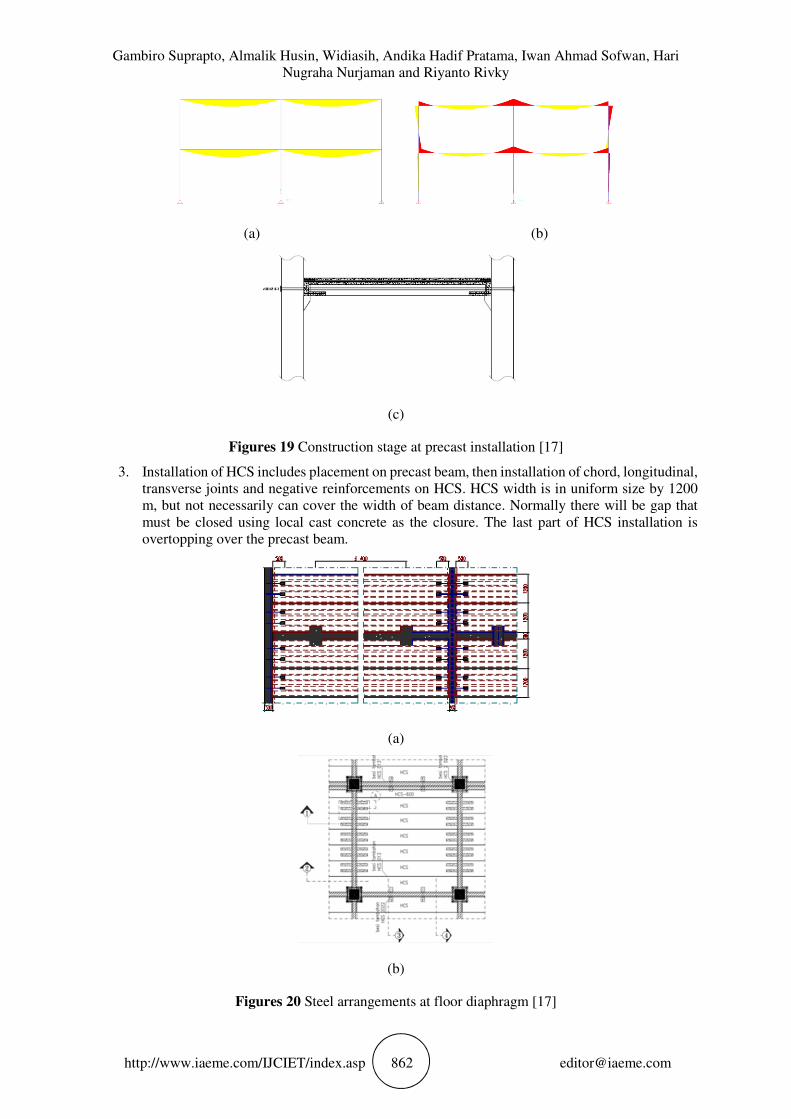
(a) (b)
(c)
Figures 19 Construction stage at precast installation [17]
3. Installation of HCS includes placement on precast beam, then installation of chord, longitudinal,
transverse joints and negative reinforcements on HCS. HCS width is in uniform size by 1200
m, but not necessarily can cover the width of beam distance. Normally there will be gap that
must be closed using local cast concrete as the closure. The last part of HCS installation is
overtopping over the precast beam.
(a)
(b)
Figures 20 Steel arrangements at floor diaphragm [17]

Full Precast Structure with Unbonded Posttension Prestressed Hybrid Frame Structures at The
Tamansari Hive office Park Building, Jakarta, Indonesia
http://www.iaeme.com/IJCIET/index.asp 863 [email protected]
(a)
(b)
(c)
Figures 21 Detail of steel reinforcments at floor diaphragm [17]
Gambiro Suprapto, Almalik Husin, Widiasih, Andika Hadif Pratama, Iwan Ahmad Sofwan, Hari
Nugraha Nurjaman and Riyanto Rivky
http://www.iaeme.com/IJCIET/index.asp 864 [email protected]
6. SUMMARY
1. Precast system can be applied to multi-storey building in seismic areas. Almost all building
components such as floors, beams and columns can be made with precast system.
2. Tamansari Hive Office Park building uses PRESSS system to anticipate seismic load. This
system is expected to reduce the damage to the building, because it uses the principle of self-
centering obtained from the use of unbonded posttension prestressed.
3. Hollow core slabs should be designed as diaphragms that can channel the lateral forces to
vertical elements (columns and shear walls). The main structure with HCS is taken into account
as a semi rigid structure. This applies as a structure that uses precast flooring. HCS is integrated
by installing reinforcements on gaps between HCS (longitudinal and transverse joints) and
reinforcements around floor areas (tension and compression chords).
4. Hollow core slab is a one-way slab that simplifies installation, as there are only 2 installation
limits, compared to two-way slabs that have 4 installation limits. With its long span, then high
installation productivity will be obtained.
5. Installation of pre-casted beams without scaffolding can accelerate the construction and makes
the floor seems roomy and clean.
REFERENCES
[1] F. Naeim, The Seismic Design Handbook, vol. 2nd Edition, Kluwer Academic Publishers,
[2] D.R. Buettner, R.J. Becker, James Beerhower, K. Boyle, J. Butler, L. Collavino, E. J.
Gregory, P. Hynes, P. Kourajian, E. Markle, J. Markle, M.J. Nimmer, W.C. Richardson Jr.,
K. Rosenstern, W. Schrooten, L. Stigler, PCI Manual for The Design of Hollow Core Slabs,
2nd Edition Precast/Prestressed Concrete Institute, 1998.
[3] ACI 318-11, Building Code Requirements for Structural Concrete (ACI 318-14) and
Commentary, American Concrete Institute, 2014.
[4] ACI 374.1-05, Acceptance Criteria for Moment Frames Based on Structural Testing,
American Concrete Institute, 2005.
[5] ACI 550.1R-01, Emulating Cast-in-Place Detailing in Precast Concrete Structures,
American Concrete Institute, 2001.
[6] ACI 550.2R-13, Design Guide for Connections in Precast Jointed Systems, American
Concrete Institute, 2013.
[7] ACI 550.3M-13, Design Specification for Unbonded Post-Tensioned Precast Concrete
Special Moment Frames Satisfying ACI 374.1, American Concrete Institute, 2013.
[8] ACI T1.2-03, Special Hybrid Moment Frames Composed of Discretely Jointed Precast and
Post-Tensioned Concrete Members, American Concrete Institute, 2003.
[9] SNI 03-1726-2002, Tata cara perencanaan ketahanan gempa untuk bangunan gedung,
Badan Standarisasi Nasional, 2002.
[10] SNI 1726:2012, Tata cara perencanaan ketahanan gempa untuk struktur bangunan gedung
dan non gedung, Badan Standarisasi Nasional, 2012.
[11] SNI 2847:2013, Persyaratan beton struktural untuk bangunan gedung, Badan Standardisasi
Nasional, 2013.
[12] S.D. Nakaki, G.R. Stevens, J.R. Harris, NEHRP Recommended Provisions: Design
Example Chapter 8 – Precast Concrete Design, FEMA P-751, 2009.
[13] D.R. Buettner, R.J. Becker, PCI Manual for The Design of Hollow Core Slabs, Second
Edition, Precast/Prestressed Concrete Institute, 1998.
[14] M.D. Herlihy, R. Park , Precast Concrete Floor Support and Diaphragm Action, 1999.
[15] S.K. Ghosh, N.M. Cleland, Untopped Precast Concrete Diaphargms in High-Seismic
Applications, PCI Journal, November – December 2002.
Full Precast Structure with Unbonded Posttension Prestressed Hybrid Frame Structures at The
Tamansari Hive office Park Building, Jakarta, Indonesia
http://www.iaeme.com/IJCIET/index.asp 865 [email protected]
[16] G. Soeprapto, M. Sunarso, Sumarsono, F. Murdono, W. Agustin, R. Siahaan, Effect of
longitudinal joint on the shear-key of hollow core slab which function as an rigid diaphargm,
Sriwijaya International Conference on Engineering, Science and Technology 2016
(SICEST 2016), Matec Web of Conferences 101, 01017 (2017).
[17] B. Raja Sekhara Reddy and K. Shyam Chamberlin. Cost Efficient On Precast Foundation
with Cast In-Situ Foundation For Multi-Storeyed Building. International Journal of Civil
Engineering and Technology, 8(1), 2017, pp. 325–328.
[18] Suma.Yarlagadda, SS.Asadi and S.S. Bhanu Prakash, Efficient Cost Management of
Materials In Conventional and Precast Construction. International Journal of Civil
Engineering and Technology, 8(1), 2017, pp. 307–311
[19] G. Soeprapto, M. Sunarso, Sumarsono, F. Murdono, W. Agustin, R. Siahaan, Effect of
longitudinal joint on the shear-key of hollow core slab which function as an rigid diaphargm,
Sriwijaya International Conference on Engineering, Science and Technology 2016
(SICEST 2016), Matec Web of Conferences 101, 01017 (2017).
[20] Mohini V. Patel and A.B.Pujari, Comparative Analysis and Design For Precast and RCC
EWS Buildings. International Journal of Civil Engineering and Technology, 8(3), 2017, pp.
670–679.