full catalog pdf - pixus technologies
TRANSCRIPT

Pixus Technologies CatalogPixus Technologies Catalog
www.pixustechnologies.com | [email protected] | US: 916.524.8242 | CAN: 519.885.5775
Kaparel, Ripac, & Vario Brand Products
The Power of Embedded Ingenuity

Front Panels – Injector/Extractor Handles . . . . . . . . . . . . . . . . . . . . . . . . . . . . . . . . . . . . . . . . . . . . . . . . . . . . . . . . . . 96
Ejector Handles Face Plate Accessories Drive Bay Chassis Solder Side Covers PMC Panels
13
Contents Kaparel/Rittal Electronic Packaging Catalog
Microcomputer Packaging Systems MPS . . . . . . . . . . . . . . . . . . . . . . . . . . . . . . . . . . . . . . . . . . . . . . . . . . . . . . . . . . . . 14
AdvancedTCA (ATCA) CompactPCI (CPCI) Compact I VMEbus Slim-Box RiTherm CompactPCI Accessories
Backplanes . . . . . . . . . . . . . . . . . . . . . . . . . . . . . . . . . . . . . . . . . . . . . . . . . . . . . . . . . . . . . . . . . . . . . . . . . . . . . . . . . . . . . . . . . . . . . 60
AdvancedTCA CompactPCI VMEbus
Peripherals . . . . . . . . . . . . . . . . . . . . . . . . . . . . . . . . . . . . . . . . . . . . . . . . . . . . . . . . . . . . . . . . . . . . . . . . . . . . . . . . . . . . . . . . . . . . . 92
Alarm Boards Power Entry Modules SCSI Drive Cards
Power Supply Units . . . . . . . . . . . . . . . . . . . . . . . . . . . . . . . . . . . . . . . . . . . . . . . . . . . . . . . . . . . . . . . . . . . . . . . . . . . . . . . . . . 138
Pluggable Open Frame ATX
Subracks . . . . . . . . . . . . . . . . . . . . . . . . . . . . . . . . . . . . . . . . . . . . . . . . . . . . . . . . . . . . . . . . . . . . . . . . . . . . . . . . . . . . . . . . . . . . . . 146
Economical EMC Railway
Cooling . . . . . . . . . . . . . . . . . . . . . . . . . . . . . . . . . . . . . . . . . . . . . . . . . . . . . . . . . . . . . . . . . . . . . . . . . . . . . . . . . . . . . . . . . . . . . . . . 220
Ricool I Ricool II Fan Trays Fans
Instrument Cases/System Enclosures . . . . . . . . . . . . . . . . . . . . . . . . . . . . . . . . . . . . . . . . . . . . . . . . . . . . . . . . . . . . . . . 230
RiBox Vario-Module RiCase
Index . . . . . . . . . . . . . . . . . . . . . . . . . . . . . . . . . . . . . . . . . . . . . . . . . . . . . . . . . . . . . . . . . . . . . . . . . . . . . . . . . . . . . . . . . . . . . . . . . . 262
Table Of Part Numbers CompactPCI Backplane Cross Reference
Section 1_2-51 4/7/04 9:21 AM Page 14

Kaparel/Rittal supplies complete plug-and-play solutions for VME and CompactPCI applications at ahigh level (up to Level 4).
Level 1 = ComponentsLevel 2 = SubassembliesLevel 3 = MPS systems wired/tested
(w/o active boards)Level 4 = MPS systems with active components
such as Drives, CPUs and System Management
Level 5 = MPS systems fully hardware and software configured
The systems are supplied fully assembled, wired andtested, including power supply unit and backplane, to the customer’s individual specifications.Consideration is also given to aspects such as ESDand EMC protection, climate control and the coding of board type plug-in units. Customer satisfaction is guaranteed, thanks to competentadvice at every stage of the process, from the initialconsultation, to application engineering, through toprototype production.
19 Plants, 40 Subsidiaries
Over 8,000 Standard Products
Involvement In Standardization Bodies
And Much More
The Slim-Box system shown here offers theoption of installing two plug-in boards per Uat the front and rear, including high-speed cPCI backplanes. Optionally available with H.110 bus.
Microcomputer systems based on tried-and-tested VMEbus technology, e.g. forhorizontal or vertical installation of VMEbusboards and drives.
15
Microcomputer Packaging Systems (MPS)Ripac AdvancedTCA® Shelves 16Backplanes for AdvancedTCA 16Horizontal Rack-mounted systems for CompactPCI 26-33Development Systems for PICMG 2.0, 2.16 and 2.17 76-79Horizontal Rack-mounted systems for VME 110-113Backplanes for VME 124-131
AdvancedTCA shelf addresses the next generation in telecomm and data embedded platforms.
Section 1_2-51 4/7/04 9:18 AM Page 16

16
AdvancedTCA is a registered trademark ofPICMG® Rittal Corporation reserves the right toimprove, alter or cancel any of its product line.
Order Information
AdvancedTCA® Shelf
Basic Mechanical Elements:The basic elements of the platform are:
The Boards: A mix of IEC 60297-3 dimensions
and PICMG 3.0 specific mechanicalsolutions.
Front Boards (8U x 6HP and 280 mm depth) contain the electronic functions and the requiredconnectors. The PCB is offset to thepitch-line by 6.61 mm and may be1.6 mm to 2.4 mm of nominal thickness and includes a componentside 1 ESD strip and componentside 2 cover attachment holes. The Front Board assembly includes,as mandatory features, a FrontPanel assembly with Alignment/GND Pin, EMC Gasket, ESD strip,Injector/Extractor/Locking handleswith optional microswitch operationfor Hot-Swap and optional M3 retention screws. A component side2 (backside) cover is for PCB stiffening and/or EMI protection is mandatory.
The Connectors: Zone 1: Power and System
Management. Zone 2: Data Transport. Zone 3: Rear I/O. Zone 1 and Zone 2 are controlled by a dedicated Alignment/KeyingDevice. Optional, additional Zone 3 applications provide for a further dedicated Alignment/Keying device.
The Subrack: The Subrack provides for the Front
Board and optional RTM interfaces. The 14 slot or the 16 slot subrack
provides for attachment points of the backplane, as well as alignment/keying, support andmechanical advantage of the insertion and extraction of FrontBoards and optional RTM’s.
The Subrack provides for theoptional Zone 3 I/O and the A/K2alignment/keying interface.
The Shelf: The Shelf consists of the integrated
Subrack, Cooling/Filter Devices,Power Entry Modules, SystemManagement Functions and CableManagement
The Shelf may support either 14slots or 16 slots (for 16 slots inquire)
The 14 slot Shelf may be 19" basedor ETSI based (for ETSI inquire)
The 16 slot Shelf may be 23" basedor ETSI based (please inquire)
The height of the Shelf may be N xU (19"/23") or N x 25 mm (ETSI)
The depth of the Shelf is approxi-mately 390 mm to fit into a 600 mmdeep cabinet
Section 1_2-51 4/7/04 9:18 AM Page 17

17
Order Information AdvancedTCA® Shelf
The 13U x 14 slot AdvancedTCADeveloper Chassis is designed to comply with the electronic requirementsof PICMG 3.0 and provide developerswith an open sided bench top. TheAdvancedTCA platform to architectapplications based on the PICMG 3.0specification. The AdvancedTCADeveloper Chassis accommodates 14slots of 8U x 6 HP x 280 mm FrontBoards and 8U x 6 HP x 70 mm RTM(Rear Transition Modules). The AdvancedTCA Developer Chassisis available with 14 slot Kaparel/RittalFull Mesh or Dual-Star architecturebackplane. The AdvancedTCADeveloper Chassis is cooled by six 115cfm – 48V DC fans and includes dual48V DC input feeds and ESD socket.
Order No.Height 14USide panel No. of slots Usable width HP For front board For RTMs Quantity For 19 inchdepth (mm) EIA 310-D/IEC60297-1
385 14 84 8U x 280 mm 8U x 70 mm 9808623
Vertical 13U - Cooling Vertical 13U - Shelf Management
The AdvancedTCA Developer Chassis
Shelf Cooling Features: Designed to cool 200 Watts/Slot Rear Baffles prevent hot air
re-circulation. RTM is cooled by vacuum effect.
(Approximately 30 Watts/Slot) Field replaceable dust filter located
below lower card guide assembly.
Management interfaces throughout theShelf enable the monitor & control of: Boards PEM (Input/Output Voltages
& Current) Blowers Air inlet temperature Remote alarm signals Air filter present sensor
Section 1_2-51 4/7/04 9:18 AM Page 18
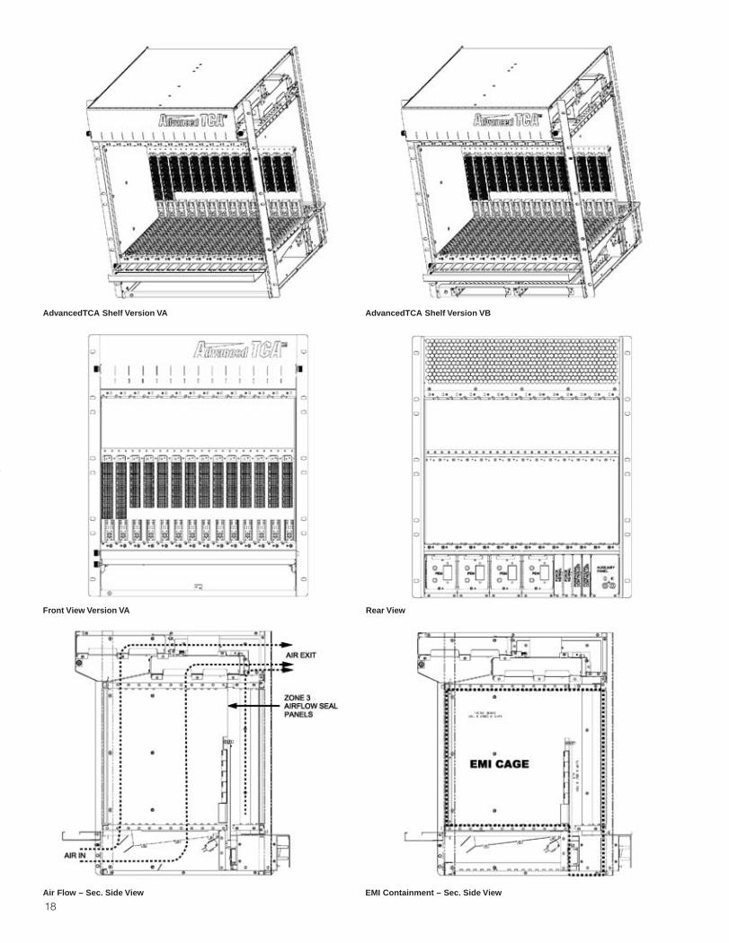
18
Front View Version VA Rear View
Air Flow – Sec. Side View EMI Containment – Sec. Side View
AdvancedTCA Shelf Version VA AdvancedTCA Shelf Version VB
Section 1_2-51 4/7/04 9:18 AM Page 19

19
Order Information AdvancedTCA® Shelf
AdvancedTCA Shelf Version VA-1Description: 19" x 13U x 385 mm depth (base)
(23"/ETSI x 13U/600 x 385 mm depth optional) 14 x 6HP slots for front boards and RTMs 14 slot full mesh backplane, bussed IPMI 2x rear PEMs, redundant (4x optional) Space for 2x rear mounted ShMC Space for 2x rear mounted peripheral controller 1 x rear mounted auxilliary telephony panel 4 x RiCool-2 blowers, dual IPMI, 180cfm/300m3/h 1 x front removable air-filter Optional front and rear cable tray
Order No.Compliant with ShMC PC PEM Qty Shelf
Bussed IPMI 1 3688305FCI Kernel x 1 optional
Kaparel/Kernel/PC 3688323 1 optionalPEM-Basic 3688378 1 optionalPEM-IPMI 3688388 1 optional
ShMC: The choice of the backplane is based on the Shelf Management Controller (ShMC) used. The functionality of the chosen ShMC will define the functionality of the Peripheral Controller (PC). 3688305 is defined for Force Computers (FCI) ShMC rear mount requirements. PEM: There are various types of Power Entry Modules (PEM) available based on application needs. A min of 2 are required, a max of 4 postions are provided for.
AdvancedTCA Shelf Version VB-1Description: 19" x 13U x 385 mm depth (base)
(23"/ETSI x 13U/600 x 385 mm depth optional) 14 x 6HP slots for front boards and RTMs 14 slot full mesh backplane, radial IPMI 2 x rear mounted PEMs (4x optional) Space for 2x front mounted ShMC Space for 2x rear mounted peripheral controller 1 x rear mounted auxilliary telephony panel 4 x RiCool-2 blowers, dual IPMI, 180cfm/300m3/h 1 x front removable air-filter Optional front and rear cable tray
AdvancedTCA Shelf Version VB-2Description: 19" x 13U x 385 mm depth (base)
(23"/ETSI x 13U/600 x 385 mm depth optional) 14 x 6HP slots for front boards and RTMs 14 slot full mesh backplane, bussed IPMI 2 x rear mounted PEMs (4x optional) Space for 2x front mounted ShMC Space for 2x rear mounted peripheral controller 1 x rear mounted auxilliary telephony panel 4 x RiCool-2 blowers, dual IPMI, 180cfm/300m3/h 1 x front removable air-filter Optional front and rear cable tray
Order No.Compliant with ShMC PC PEM Qty Shelf
Radial IPMI 1 3688301Intel CMM x 1 optional
Kaparel/CMM/PC 3688322 1 optionalPEM-Basic 3688378 1 optionalPEM-IPMI 3688388 1 optional
ShMC: The choice of the backplane is based on the Shelf Management Controller (ShMC) used. The functionality of th chosen ShMC will define the functionality of the Peripheral Controller (PC). 3688301 is defined for Intel CMM requirements. PEM: There are various types of Power Entry Modules (PEM) available based on application needs.A min of 2 are required, a max of 4 postions are provided for.
Order No.Compliant with ShMC PC PEM Qty Shelf
Bussed IPMI 1 3688302PP ShMM 3688320 1 optional
Kaparel/ShMM/PC 3688324 1 optionalPEM-Basic 3688378 1 optionalPEM-IPMI 3688388 1 optional
ShMC: The choice of the backplane is based on the Shelf Management Controller (ShMC) used. The functionality of th chosen ShMC will define the functionality of the Peripheral Controller (PC). 3688302 is defined for Pigeon Point (PP) ShMM requirements. PEM: There are various types of Power Entry Modules (PEM) available based on application needs.A min of 2 are required, a max of 4 postions are provided for.
AdvancedTCA Shelf Version VB-3Description: 19" x 13U x 385 mm depth (base)
(23"/ETSI x 13U/600 x 385 mm depth optional) 14 x 6HP slots for front boards and RTMs 14 slot full mesh backplane, bussed IPMI 2 x rear mounted PEMs (4x optional) Space for 2x front mounted ShMC Space for 2x rear mounted peripheral controller 1 x rear mounted auxilliary telephony panel 4 x RiCool-2 blowers, dual IPMI, 180cfm/300m3/h 1 x front removable air-filter Optional front and rear cable tray
Order No.Compliant with ShMC PC PEM Qty Shelf
Bussed IPMI 1 3688343FCI Kernel x 1 optional
Kaparel/Kernel/PC 3688323 1 optionalPEM-Basic 3688378 1 optionalPEM-IPMI 3688388 1 optional
ShMC: The choice of the backplane is based on the Shelf Management Controller (ShMC) used. The functionality of th chosen ShMC will define the functionality of the Peripheral Controller (PC). 3688343 is defined for Force Computers (FCI) ShMC front mount requirements. PEM: There are various types of Power Entry Modules (PEM) available based on application needs.A min of 2 are required, a max of 4 postions are provided for.
Section 1_2-51 4/7/04 9:18 AM Page 20

20
Order Information
AdvancedTCA® Backplanes
The AdvancedTCA Backplanes:Kaparel/Rittal are active members of the PICMG 3.0 subcommittee including acontract for the simulation and routing analysis for the Dual Star, Dual-Dual Starand Full Mesh configurations. Simulations were run using a minimum speed of3.125 Gbps. For the base and Fabric Interface, an 8 mil line width, 10 mils withinthe pair and 35 mils pair to pair achieving a low 0.2% noise coupling. Simulationswere also run on 5 Gbps and above but showed that steps like back drillingand/or silicon equalization options may be required.Kaparel/Rittal offers a complete range of off-the-shelf 14 and 16 slot versions oftheir AdvancedTCA backplanes including Full Mesh, Dual Star, Dual-Dual Star andDual Dual Stare with 1x Mesh overlay. In addition custom designs are available for specific customer applications. A 4 slot Full Mesh version will be available for horizontal chassis applications.The Dual Star version is completed in 14 layers and the Full Mesh in 36 layers,both in Nelco material. This material allows a thinner board as well as provides thesignal integrity required for AdvancedTCA based applications. The backplanes usethe high speed AMP/ERNI ZD connector in zone 2 for signal noise and ease ofrouting differential pairs. The routing uses broadside differential pairs providing lownoise coupling without additional signal layers.Off-the-shelf or custom AdvancedTCA solutions available from Kaparel/Rittal willallow you to get your applications quickly to the market.
The 14 slot Full Mesh AdvancedTCA Backplane
Cool Running: Actual thermal image of Kaparel/Rittal 11401 backplane under fullload conditions – 14 slots at 200W. The red imaging at top is feed through fromload resistors.
The AdvancedTCA BackplanesOrder No. Model No. Slots Description3688760 10401 4 Full mesh bussed IPMI3688763 11401 14 Full mesh bussed IPMI3688307 11404 14 Dual Star bussed IPMI3688317 11601 16 Full mesh bussed IPMI3688429 11604 16 Dual Star bussed IPMI
Note: Radial IPMI versions available, please contact the factory.
AdvancedTCA Shelf AccessoriesAccessories Description Used For Quantity Order No.
Zone 3 air seal 6HP - FR4 Zone 3 1 3688290Filler panel (FP) 8U x 6HP front/rear 1 3688266
FP w/air management 8U x 6HP x 280 mm front 1 3688267FP w/air management 8U x 6HP x 70 mm rear (RTM) 1 3688268
AdvancedTCA Shelf Version HA-1 – HorizontalDescription: 19" x 3U x 385 mm depth (base) 4 x 6HP slots for front boards and RTMs 4 slot full mesh backplane, bussed IPMI Redundant power entry on rear Space for 2x rear mounted ShMC Telco Alarming, rear Front removable fan tray, right side (2 fans) Front removable fan tray, left side (2 fans) Front removable filter, right side Airflow, right to left
Order No.Compliant with ShMC PC PEM Qty Shelf
Bussed IPMI 1 3688299FCI Kernel x 1 optional
Kaparel/Kernel/PC on board 1 included
Note: The choice of the backplane is based on the Shelf Management Controller (ShMC) used. The functionality of th chosen ShMC will define the functionality of the Peripheral Controller (PC). 3688299 is defined for Force Computers (FCI) ShMC front mount requirements. Front to back airflow is not achievable in the 19" format.
Note: Due to the flexibility of the PICMG 3.0 Specification many ShMC solutions may emerge. The above shelf designs are based on sound mechanical research.
Section 1_2-51 4/7/04 9:18 AM Page 21

21
Order Information AdvancedTCA® Face Plates For Front Boards And RTMs
Kaparel/Rittal offers a complete range of theAdvancedTCA face plates, filler panels and handles in brushed stainless steel.A complete custom face plate and filler panel programis available providing custom cut-outs, silk screen oroverlays and several handle styles including lockingand microswitch activation designs. The face platesand filler panels are also available with optional EMCgaskets – adhesive foam, adhesive finger stock ormechanical snap-in styles. The handle locking deviceacts as a grounding feature and securely locks thehandle under seismic Zone 4 conditions (NEBS Level 3).The Kaparel/Rittal AdvancedTCA optional face plateand filler panel design are to be used for both theFront Board and RTM assembled in mirror image. For the front board, the mandatory Component Side 2cover is incorporated into the face plate design. A front slot or RTM air management version is available for Zone 3. Each Face Plate comes with 2 locking latches
attached Injector/extractor handles, HDW and EMI gaskets
must be purchased separately Face Plates provide for the I/O interface Filler plates are used in place of unused/reserved
slots and provide for EMI protection and air-flowmanagement
The AdvancedTCA Face Plate of 6HP is defined inPICMG 3.0
I/O devices requiring a return path to shelf groundshall implement this return path through the FacePlate alignment/GND pin/receptacle
Handle Type 1Microswitch A+B (B position for max I/O)
Type Qty Order No. Material FinishA+B 1 9805161 Steel Zinc plated
B 1 9808691 Steel Zinc plated
Filler Panel – RTM withair management
Filler Panel – Front with air mangement
Filler Panel – Front/RTMwithout air management
Handle Type 1 – Handle w/microswitch A+B actuator
Face Plate Without Side2 Cover – Front/RTM
Face Plate With Side 2Cover – Front
Face Plate With Side 2Cover – RTM
Face Plate With Side 2 Cover – RTM (mandatory)HP Qty Order No. Material6 1 9808764 Stainless
12 1 Inquire Stainless
Face Plate Without Side 2 Cover – Front/RTM (optional)HP Qty Order No. Material6 1 9805172 Stainless
12 1 Inquire Stainless
Face Plate With Side 2 Cover – Front (mandatory)HP Qty Order No. Material6 1 9805174 Stainless
12 1 Inquire Stainless
Filler Panel Without Airflow Baffle – Front/RTM(optional)
Type HP Qty Order No. MaterialFront 6 1 3688266 StainlessRear 6 1 3688266 Stainless
Filler Panel With Airflow Baffle – Front (mandatory)Type HP Qty Order No. MaterialFront 6 1 3688267 Stainless
Filler Panel With Airflow Baffle – Rear (mandatory)Type HP Qty Order No. MaterialRear 6 1 3688268 Stainless
EMI Gaskets For Face Plate And Filler PanelsType U Qty Order No. Material
F 8 1 9805160 FoamS 8 1 3688342 StainlessC 8 1 3654346 Stainless
HardwareType Used for Qty Order No. Head
M2.5 X 6 PCB mtg. 100 3688397 PhillipsM3 X 10 Backplane 100 3688386 Phillips
Handle Type 1 – Handle w/microswitch B actuator
9805172 – Face platew/optional handle and EMI gasket
3688266 – Filler panelw/optional EMI gasket
Handle Type 2 – Handle w/microswitch A actuator
Handle Type 2 – Handle wo/microswitch actuator
Handle/Locking/Microswitch
Face Plate Overlay
AA
C
B
B
Handle Type 2Microswitch A position for 4xPMC, when PMC ismounted to the most outside position of the host
Type Qty Order No. Material FinishA 1 9808692 Steel Zinc platedC 1 9808693 Steel Zinc plated
Section 1_2-51 4/7/04 9:19 AM Page 22

22
Overview Of Systems
CompactPCI
CompactPCI “Slim-Box”
1, 2, 3, 4U/2, 4, 6, 8 slot in AC or DC inputOrder No. see pages 26-33For backplanes see page 61-78
ApplicationsConfiguration of 482.6 mm (19") industrialcomputer systems to the CompactPCI specifications for Telecommunications Automation
Design Features 482.6 mm (19") rack-mounted system for
horizontal installation of computer boardsat the front, and I/O boards at the rear
1U, 2U, 3U, 4U, 300 mm deep Standard cooling from left to right or
right to left Sheet steel, spray-finished (black) Including backplane and fan Fully assembled, wired and tested Configuration for CompactPCI boards to
CompactPCI Spec. 2.0 and 2.1
User Benefits Horizontal installation of double
Euroboards Maximum installation with minimal space
requirements 2/4/6/8 slots at the front for 160 mm and
at the rear for 80 mm boards Hot swap-compatible power supply units,
optionally AC or DC EMC and ESD protection Fully assembled, wired and tested Integral cooling from left to right Complies with CompactPCI spec. 2.0
and 2.1, IEC 60 297-3 and IEEE1101.1/1101.10/1101.11
CompactPCI Systems
4U and 7U, 8 slotOrder No. see page 38For backplanes see pages 61-78
User Benefits Vertical installation of Euroboards/double
Euroboards EMC and ESD protection Fully assembled, wired and tested Targeted air routing from bottom to top Keyable guide rails Complies with CompactPCI spec. 2.0
and 2.1, IEC 60 297-3 and IEEE1101.1/1101.10
CompactPCI Systems
3U, 5 slot/4U, 7 slot horizontalOrder No. see page 38For backplanes see pages 61-78
User Benefits Horizontal installation of double
Euroboards EMC and ESD protection Fully assembled, wired and tested Targeted air routing from front to rear Keyable guide rails Complies with CompactPCI spec. 2.0
and 2.1, IEC 60 297-3 and IEEE1101.1/1101.10
ApplicationsConfiguration of 482.6 mm (19") industrialcomputer systems to the CompactPCI specifications for Telecommunications Automation
Design Features 482.6 mm (19") rack-mounted system for
horizontal installation of doubleEuroboards
3U or 4U, 405 mm deep Clear chromated aluminum Including backplane and power
supply unit Fully assembled, wired and tested Horizontal installation space for double
Euroboards: 5 or 7 slots Configuration for CompactPCI boards to
CompactPCI Spec. 2.0 and 2.1
ApplicationsConfiguration of 482.6 mm (19") industrialcomputer systems to the CompactPCI specifications for Telecommunications Automation
Design Features 482.6 mm (19") rack-mounted system for
vertical installation of Euroboards/doubleEuroboards
4 or 7U, 405 mm deep Clear chromated aluminum Including backplane and power
supply unit Fully assembled, wired and tested Installation space for Euroboards/double
Euroboards: 8-21 slots Configuration for CompactPCI boards to
CompactPCI Spec. 2.0 and 2.1 3U x 160 mm or 6U x 160 mm boards
Section 1_2-51 4/7/04 9:19 AM Page 23

23
Overview Of Systems CompactPCI
CompactPCI Systems
7U, 8 slotOrder No. see page 40For backplanes see pages 61-78
User Benefits Vertical installation of double Euroboards EMC and ESD protection Fully assembled, wired and tested Targeted air routing from front to rear Keyable guide rails Complies with CompactPCI spec. 2.0
Rev. 3.0, IEC 60 297-3 and IEEE1101.1/1101.10
CompactPCI, “Compact-I”
User Benefits Customized system production Cost-effective production of large
quantities
CompactPCI Systems
9U, 12 slot with RiCool and Rear I/OOrder No. see page 44For backplanes see pages 61-78
User Benefits Vertical installation of double Euroboards EMC and ESD protection Fully assembled, wired and tested Targeted air routing Rear I/O transition modules Keyable guide rails Effective ventilation with two RiCool
blowers (204 m3/h) Complies with CompactPCI spec. 2.0
Rev. 3.0, IEC 60 297-3 and IEEE1101.1/1101.10
ApplicationsConfiguration of 482.6 mm (19") industrialcomputer systems to the CompactPCI specifications for Telecommunications Automation Medical
Design Features 482.6 mm (19") rack-mounted system for
vertical installation of double Euroboards 9U, 290.5 mm deep, with rear I/O modules Clear chromated aluminum Including backplane, power supply unit
and 2 radial fans Fully assembled, wired and tested Installation space for plug-in boards:
8 slots Configuration for CompactPCI boards to
CompactPCI Spec. 2.0 Rev. 3.0
ApplicationsConfiguration of 482.6 mm (19") industrialcomputer systems to the CompactPCI specifications for Telecommunications Automation Data communications Computer telephony
Design Features 482.6 mm (19") rack-mounted system for
vertical installation of double Euroboards Outer enclosure made from 1 mm sheet
steel Pull-out interior enclosure made from
aluminum Customer-specific configuration Front boards 6U x 160 mm Rear RTM 6U x 80 mm
ApplicationsConfiguration of 482.6 mm (19") industrialcomputer systems to the CompactPCI specifications for Telecommunications Automation
Design Features 482.6 mm (19") rack-mounted system for
vertical installation of Euroboards/doubleEuroboards
7U, 405 mm deep Clear chromated aluminum Including backplane and power
supply unit Fully assembled, wired and tested Installation space for plug-in boards:
8 slots Configuration for CompactPCI boards to
CompactPCI Spec. 2.0 Rev. 3.0 6U x 160 mm front boards
10U, 17 slot with RiCool and Rear I/OOrder information see page 52For backplanes see page 61-78
Section 1_2-51 4/7/04 9:19 AM Page 24

In Detail: Systems For
CompactPCI
Side Panels And Flanges of clearchromated aluminum
10 mm Pitch Pattern of holes in theside panels facilitates individualsystem configuration
Keyable Red Guide Rails fordefined positioning of the CPU
Horizontal Rails with 10 mm extension for injector/extractor handles
Design Features
Based on the PCI bus architecture, the CompactPCI bus was developedas an industry-compatible version for tough industrial applications. Ituses the tried-and-trusted single and double-Euroboard format. Themechanical requirements conform to IEEE 1101.1/10/11, which meanssimple insertion and with drawal of connectors with a large number ofpins, an ESD concept, as well as coding of the board-type plug in units.
Conductive Surface Finish of allsystem components.
EMC Gaskets of stainless steelmake contact with the individualcomponents.
EMC Front Panels with EMC gaskets ensure reliable contact.
EMC Measures
ESD ProtectionESD pin (C) and ESD contact in theguide rail (A) to discharge staticcharges before making contact withthe board type plug-in unit.
ESD Contactin the PCB guide (B) ensures permanent, direct discharge via the PCB.
ESD Protection
Safety Groundprovides a singe earth ground contact per rear I/O module. Parts are UL recognized.
Maximum Airflow due to the narrow design of the guide railsand horizontal rails.
Individual Airflow Managementensures controlled airflow andoptimum heat dissipation,optionally from bottom to top orfrom front to rear.
RiCool Flat-Pack Blowerensures optimum ventilation. 1U,hotswap-compatible, 204 m3/h,including speed control and faultalarm signal.
Climate Control
Based on the Ripac subrack system, Kaparel/Rittal offers completestandardized systems, including power supply unit and backplane, fullyassembled, wired and tested. In addition to the preassembled systemsshown here, individual solutions can also be configured to suit specificrequirements. We will be happy to assist you at every stage of theprocess, from consultancy and development right through to production.
24
1
2
3
4
Section 1_2-51 4/7/04 9:19 AM Page 25

25
Systems for the configuration ofindustrial computers to theCompactPCI specification
Fully assembled, wired and tested,including backplane and powersupply unit
Individual cooling concepts Conforms to IEC 60 297-3 and IEEE
1101.1/10/11, as well asCompactPCI PICMG 2.0
Product Information Systems For CompactPCI
Backplanes High-speedCompactPCI backplanes. Optionallywith H.110 and connectors for bridges.
Power Supply Units variousinputs/outputs, plug-type or open frame.
Insertion/Extraction Handlesto reliably overcome high insertion/extraction forces.
Live Insertion Microswitches in the insertion/extraction handles de-activate the board type plug-inunit before starting the disconnectionprocess, and activate during insertion.
System Configuration
4
2
5
3
1
5
Section 1_2-51 4/7/04 9:19 AM Page 26

26
Order Information
Slim-Box-AC Maximum Cooling Rack-Mounted System 1U, 2 Slot And 2U, 4 Slot For CompactPCI
Order No. Order No. PageMPS system MPS system
U 1 2Depth 300 mm 300 mmFor PCB depth
- front 160 mm 160 mm- rear 80 mm 80 mm
Part No. 3689177 3689178Model No. 7010 7020Mechanical Supply IncludesDescription Material482.6 mm (19") rack-mounted enclosure with Sheet steel, 1 1
- front/rear slots for boards spray finished 2 4- front slots for PSU 1 2
Guide rails, keyable Polycarbonate 10 20Electrical/Electronic Supply Includes
Technical specificationsMonolithic backplane cPCI 64 bit/66 MHz 1 1For alternative and PICM 2.16, inquire and H.110Power input module with power switch, line filter and fuse 1 1DC fan, left see opposite 3 2DC fan, right see opposite 4 3AccessoriesAC power supply unit* 175 W 9805701 9805701 142AC power supply unit* 200 W 9805703 9805703 142AC power supply unit* 250 W 9805705 9805705 142EMC front panel 6U, 4HP 3685186 3685186 101EMC front panel 6U, 8HP 3685190 3685190 101EMC front panel 3U, 4HP 3685178 3685178 101EMC front panel 3U, 8HP 3685182 3685182 101H.110, 48 V connection cable 3688697 3688697
* Note: These power supplies do not require a minimum load to operate. For power supplies that are used under full load condition, you may want to use the same power supply which requires a minimum load of approximately 5%. These PSU are available. Please inquire.
Note: For open frame or ATX power supply solutions, please contact factory
Model No.PS3310PS3312PS3314
87A10013-A01
Section 1_2-51 4/7/04 9:19 AM Page 27

27
Order Information Slim-Box-AC Rack-Mounted System 1U And 2U For CompactPCI
Technical Specifications: 1 or 2U rack-mounted enclosure
with 482.6 mm (19") mountingbrackets (may be offset approximately 100 mm to the rear)
2/4 slots for cPCI boards at the frontand rear
Enclosure cooling from left to right EMC and ESD-compatible
configuration Integral Monolithic cPCI backplane
64 bit/66 MHz with H.110 bus on J4 Power input module Including fan:
for 1U: 12 VDC, 21 m3/h, for 2U: 12 VDC, 74 m3/h
Optional: Hot swap-compatiblepower supply units with current splitting for redundancy operation(2U)
Custom versions available onrequest
Conforms to IEEE 1101.1/10/11,CompactPCI Spec. 2.0
AC – DC
Power Supply Unit175 W, hot swap-compatible, Order No. see page 90.Note: For open frame or ATX powersupply solutions, please contact factory
Monolithic cPCI Backplanewith H.110 bus (from 2U).
Power Input Module
Section 1_2-51 4/7/04 9:19 AM Page 28

28
Order Information
Slim-Box-AC Rack-Mounted System 3U, 6 Slot And 4U, 8 Slot For CompactPCI
Order No. Order No. PageMPS system MPS system
U 3 4Depth 300 mm 300 mmFor PCB depth- front 160 mm 160 mm- rear 80 mm 80 mmPart No. 3689179 3689180Model No. 7030 7040Mechanical Supply IncludesDescription Material482.6 mm (19") rack-mounted enclosure with Sheet steel, 1 1- front/rear slots for board spray finished 6 8- front slots for PSU 3 3Guide rails, keyable Polycarbonate 30 40Electrical/Electronic Supply Includes
Technical specificationsMonolithic backplane cPCI 64 bit/33 MHz 1 1For alternative and PICMC 2.16, inquire and H.110Power input module with power switch, line filter and fuse 1 1DC fan, left See opposite 1 4DC fan, right See opposite 1 + 1 6AccessoriesAC power supply unit* 175W 9805701 9805701 142AC power supply unit* 200W 9805703 9805703 142AC power supply unit* 250W 9805705 9805705 142EMC front panel 6U, 4HP 3685186 3685186 101EMC front panel 6U, 8HP 3685190 3685190 101EMC front panel 6U, 12HP 3685192 3685192 101EMC front panel 6U, 16HP 3685349 3685349 101EMC front panel 3U, 4HP 3685178 3685178 101EMC front panel 3U, 8HP 3685182 3685182 101EMC front panel 3U, 12HP 3685184 3685184 101EMC front panel 3U, 16HP 3685348 3685348 101H.110, 48 V connection cable 3688697 3688697 –
* Note: These power supplies do not require a minimum load to operate. For power supplies that are used under full load condition, you may want to use the same power supply which requires a minimum load of approximately 5%. These PSU are available. Please inquire.
Note: For open frame or ATX power supply solutions, please contact factory
Model No.PS3310PS3312PS3314
87A10013-A01
Section 1_2-51 4/7/04 9:19 AM Page 29

29
Order Information Slim-Box-AC Rack-Mounted System 3U And 4U For CompactPCI
Technical Specifications: 3 or 4U rack-mounted enclosure
with 482.6 mm (19") mountingbrackets (may be offset approximately 100 mm to the rear)
6/8 slots for cPCI boards at the frontand rear
Enclosure cooling from left to right EMC and ESD-compatible
configuration Integral Monolithic cPCI backplane
64 bit/33 MHz with H.110 bus on J4 Power input module Including fan:
for 3U: 12 VDC, 195 m3/h or 74 m3/h,for 4U: 12 VDC, 74 m3/h
Optional: Hot swap-compatiblepower supply units with currentsplitting for redundancy operation
Custom versions available onrequest
Conforms to IEEE 1101.1/10/11,CompactPCI Spec. 2.0
Power Supply Units, redundant, Order No. see page 90.Note: For open frame or ATX powersupply solutions, please contact factory
Fan in the side panel. Monolithic cPCI Backplanewith H.110 bus.
Section 1_2-51 4/7/04 9:19 AM Page 30

30
Order Information
Slim-Box-DC Rack-Mounted System 1U, 2 Slot And 2U, 4 Slot For CompactPCI
Order No. Order No. PageMPS system MPS system
U 1 2Depth 300 mm 300 mmFor PCB depth
- front 160 mm 160 mm- rear 80 mm 80 mm
Part No. 3689181 3689182Model No. 7010-DC 7020-DCMechanical Supply IncludesDescription Material482.6 mm (19") rack-mounted enclosure with Sheet steel, 1 1
- front/rear slots for boards paint finished 2 4- front slots for PSU
Guide rails, keyable Polycarbonate 10 20Electrical/Electronic Supply Includes
Technical specificationsMonolithic backplane cPCI 64 bit/66 MHz 1 1For alternative and PICMG 2.16, inquire and H.110Power entry module with breaker Single DualDC fan, left See opposite 3 2DC fan, right See opposite 4 3AccessoriesDC power supply unit* 175W 9805702 9805702 142DC power supply unit* 200W 9805704 9805704 142DC power supply unit* 250W 9805706 9805706 142EMC front panel 6U, 4HP 3685186 3685186 101EMC front panel 6U, 8HP 3685190 3685190 101EMC front panel 3U, 4HP 3685178 3685178 101EMC front panel 3U, 8HP 3685182 3685182 101EMC front panel 3U, 16HP 3685348 3685348 101EMC front panel 3U, 16HP 3685348 3685348 101H.110, 48 V connection cable 3688697 3688697 –
* Note: These power supplies do not require a minimum load to operate. For power supplies that are used under full load condition, you may want to use the same power supply which requires a minimum load of approximately 5%. These PSU are available. Please inquire.
Note: For open frame or ATX power supply solutions, please contact factory
Model No.PS3311PS3313PS3315
87A10013-A01
Section 1_2-51 4/7/04 9:19 AM Page 31

31
Order Information Slim-Box-DC Rack-Mounted System 1U And 2U For CompactPCI
Technical Specifications: 1 or 2U rack-mounted enclosure
with 482.6 mm (19") mountingbrackets (may be offset approximately 100 mm to the rear)
2/4 slots for cPCI boards at the frontand rear
Enclosure cooling from left to right EMC and ESD-compatible
configuration Integral Monolithic cPCI backplane
64 bit/66 MHz with H.110 bus on J4 Power input module Including fan:
for 1U: 12 VDC, 21 m3/h, for 2U: 12 VDC, 74 m3/h
Optional: Hot swap-compatiblepower supply units with current splitting for redundancy operation(2U)
Custom versions available onrequest
Conforms to IEEE 1101.1/10/11,CompactPCI Spec. 2.0
Power Supply Unit175 W, hot swap-compatible, Order No. see page 90.Note: For open frame or ATX powersupply solutions, please contact factory
Monolithic cPCI Backplanewith H.110 bus (from 2U).
Power Input Module
Section 1_2-51 4/7/04 9:19 AM Page 32

32
Order Information
Slim-Box-DC Rack-Mounted System 3U, 6 Slot And 4U, 8 Slot For CompactPCI
Order No. Order No. PageMPS system MPS system
U 3 4Depth 300 mm 300 mmFor PCB depth- front 160 mm 160 mm- rear 80 mm 80 mmPart No. 3689183 3689184Model No. 7030-DC 7040-DCMechanical Supply IncludesDescription Material482.6 mm (19") rack-mounted enclosure with Sheet steel, 1 1- front/rear slots for board paint finished 6 8- front slots for PSU 3 3Guide rails, keyable Polycarbonate 30 40Electrical/Electronic Supply Includes
Technical specificationsMonolithic backplane cPCI 64 bit/33 MHz 1 1For alternative and PICMG 2.16, inquire and H.110Power entry module with breakers Dual DualDC fan, left See opposite 1 4DC fan, right See opposite 1 + 1 6AccessoriesDC power supply unit* 175W 9805702 9805702 142DC power supply unit* 200W 9805704 9805704 142DC power supply unit* 250W 9805706 9805706 142EMC front panel 6U, 4HP 3685186 3685186 101EMC front panel 6U, 8HP 3685190 3685190 101EMC front panel 6U, 12HP 3685192 3685192 101EMC front panel 6U, 16HP 3685349 3685349 101EMC front panel 3U, 4HP 3685178 3685178 101EMC front panel 3U, 8HP 3685182 3685182 101EMC front panel 3U, 12HP 3685184 3685184 101EMC front panel 3U, 16HP 3685348 3685348 101H.110, 48 V connection cable 3688697 3688697 –
* Note: These power supplies do not require a minimum load to operate. For power supplies that are used under full load condition, you may want to use the same power supply which requires a minimum load of approximately 5%. These PSU are available. Please inquire.
Note: For open frame or ATX power supply solutions, please contact factory
Model No.PS3311PS3313PS3315
Section 1_2-51 4/7/04 9:19 AM Page 33

33
Order Information Slim-Box-DC Rack-Mounted System 3U And 4U For CompactPCI
Technical Specifications: 3 or 4U rack-mounted enclosure
with 482.6 mm (19") mountingbrackets (may be offset approximately 100 mm to the rear)
6/8 slots for cPCI boards at the frontand rear
Enclosure cooling from left to right EMC and ESD-compatible
configuration Integral Monolithic cPCI backplane
64 bit/33 MHz with H.110 bus on J4 Power input module Including fan:
for 3U: 12 VDC, 195 m3/h or 74 m3/h,for 4U: 12 VDC, 74 m3/h
Optional: Hot swap-compatiblepower supply units with currentsplitting for redundancy operation
Custom configurations available onrequest
Conforms to IEEE 1101.1/10/11,CompactPCI Spec. 2.0
Power Supply Units, redundant, Order No. see page 90.Note: For open frame or ATX powersupply solutions, please contact factory
Fan in the side panel. Monolithic cPCI Backplanewith H.110 bus.
Section 1_2-51 4/7/04 9:19 AM Page 34

34
Order Information
CompactPCI Developer Chassis 8 Slot With RTM
Order No.U 8.5
Side panel Usable width For PCB For cPCIdepth (mm) HP
292 42 6U x 160 mm 9807801maximum 10.5 cPCI slots at 4 HP 60 x 80 mm RTMs
Mechanical Supply IncludesItem Description Material Quantity Page
1 Ripac horizontal rails Aluminum, clear chromated Set 1722 EMC gaskets Stainless steel Various 1003 Side plates Steel, 1 mm plated/painted 24 Guide rails gray/yellow, keyable Polycarbonate UL 94-V0 14 575 Guide Rails red (CPU), keyable Polycarbonate 2 576 Guide rails gray/yellow, RTM’s keyable 16 5778 ESD clips for PCB ESD wipe Stainless steel 16 57910 ESD jack11 2.5U bottom bolted panel, with IEC AC power 2.5 mm aluminum, clear chromated 1
entry/line filter and fan12 Rear bolted panel, 4U, with IEC AC power entry/line filter 2.5 mm aluminum, clear chromated
and fanElectrical/Electronic Supply Includes
Electrical specifications13 Check for PICMG 2.0/2.1 + H.110 backplanes RP 4400 3686877 74
PICMG 2.16 backplanes – 8 slot RP 4918 3686414 76PICMG 2.17 backplanes – 8 slot RP 4818 3689195 78
14 CompactPCI backplane 6.5U x 8 slot See PICMG 2.0/2.1 RP 1400 3686549 7415 AC fans 54 cfm (UL, VDE, CSA) 2 22616 IEC AC socket with line filter 6A (VDE, UL, CSA) 1 12317 DC terminal block for bench top PSU 11819 Optional on/off switch20 AC cable harness 1 DC available upon request
Designed for the hardware and software development of cPCI boardsand systems. An inexpensive solutionwith maximum board access. For usewith Lab type Bench Top PSU.
During the process of developingCompactPCI boards, access to components may be required. This canbe done by using a cPCI extendercard, which tends to be expensive andmay cause possible distortion to sensitive signals. Kaparel/Rittal, theoriginal cPCI packaging company, isintroducing a simple and inexpensivesolution to test and debug cPCI front-loaded and rear-loaded I/O boards –the Kaparel/Rittal cPCI DeveloperSubrack. The cPCI Developer isdesigned so that the power for thebackplane will come from the existingbench top supply. Alternatively, a pluggable power supply may beused in place of PCB slots, or an inexpensive ATX power supply may beplugged directly into the backplane.
Section 1_2-51 4/7/04 9:19 AM Page 35

35
Order Information CompactPCI Developer Chassis
Technical Description:Vented system, 292 mm deep, for desktop applicationPrepared to accommodateCompactPCI boards and drivesDesigned to utilize bench top power suppliesComplies with IEC 60297-3/ -4/ -5-1xx; IEEE 1101.1/.10/.11
Features 8.5UPrepared for the horizontal installation of cPCI front boards •8 slot x 6U x 160 mm boards Max 10 slot x 6U x 160 mm boards8 slot x 6U x 80 mm RTMs. Max 10 slot x 6U x 80 mm RTMs •Optionally, 6U may be converted to 2 x 3U sections (1 slot to 10 slots)For the optional installation of drives •Front/rear interface for CompactPCI defined injector/extractor handles •Keyable PCB guide/slot positions per PICMG 2.10 •Red guides for the system slot •Green guide rails for the pluggable PSU slotGray/yellow guides for peripheral slot identification •ESD clips for PCB ESD wipe •Optional ESD clips for front panel ESD protectionOptional 30A ground sockets for RTM protectionVertical bottom/top cooling •Fully wired and tested •
Options To Be Considered: For alternative cPCI backplanes,
see pages 73-78 For bridges, see page 83 For alternative cPCI/H.110
backplanes, see pages 74-75 For alternative PICMG 2.16 fabric
backplanes, see page 78 For alternative PICMG 2.17 star
fabric backplanes, see page 76
For alternative PSU backplanes, see pages 88-91
For power supplies, see page 91 For DC power entry module,
see page 92 For alarm board, see pages 93-94 For hard disk drive modules,
see page 95 For RiCool blowers,
see pages 222-225
For system thermal evaluation tools,see page 54
For EMC filler panels, see pages 208-209
For front panels and injector/extractor handles, see page 98
For 30A RTM ground contacts, see page 58
Section 1_2-51 4/7/04 9:19 AM Page 36

36
Order Information
Rack-Mount System For CompactPCI 3U, 5 Slot And 4U, 7 Slot
Order No. Order No.U 3 4
Side panel For PCB For cPCI For cPCIdepth (mm)
358 6U x 160 mm 9808466 980802960 x 80 mm RTMs
Mechanical Supply IncludesItem Description Material Quantity Page
1 Ripac subrack system Aluminum, clear chromated 1 1 1462 EMC gaskets Stainless steel Various Various 1003 Covers 1 mm aluminum, clear chromated 2 2 188-1914 Guide rails gray/yellow, keyable Polycarbonate UL 94-V0 8 12 575 Guide rails red (CPU), keyable Polycarbonate 2 2 576 Guide rails gray/yellow, RTMs, keyable 10 14 577 Guide rails green, PSU 2 2 578 ESD clips for PCB ESD wipe Stainless steel 10 14 57910 3U x 21HP front panel 2.5 mm aluminum, clear chromated 1 1 –
4U x 21HP front panel11 Rear bolted panel, 3U, with IEC AC power entry/line filter 2.5 mm aluminum, clear chromated 1
and fan12 Rear bolted panel, 4U, with IEC AC power entry/line filter 2.5 mm aluminum, clear chromated 1
and fanElectrical Supply Includes
Electrical specifications13 CompactPCI backplane 3.5U x 5 slot See PICMG 2.0/2.1 1 7214 CompactPCI backplane 6.5U x 7 slot See PICMG 2.0/2.1 1 7315 DC fans 12 V (UI, VDE, CSA) 226
optional speed control16 IEC AD socket with line filter 6A (VDE, UL, CSA) 1 1 12317 Hot swap PSU, 175W +3.3V/25A, +5V/25A, 97
(UL, VDE, CSA) +12V/8A, -12V/7A18 Power supply 175 W with on/off switch cable 9719 LED display module with on/off switch 3U x HP, 4U x HP +3.3V, +5V, +/-12V fan failure 1 1 12220 AC cable harness 1 DC available upon request
For 300W systems for front boards andRTMs, front to back airflow, no air filter.
Section 1_2-51 4/7/04 9:19 AM Page 37

37
Order Information Rack-Mount System For CompactPCI 3U, 5 Slot And 4U, 7 Slot With RTMs
Technical Description:Vented system, 358 mm deep, forinstallation in 19" (486.2 mm) racks,cabinets or cases. Prepared to accommodateCompactPCI boards and drivesComplies with IEC 60297-3/ -4/ -5-1xx;IEEE 1101.1/.10/.11
Features 3U/4UPrepared for the horizontal installation of cPCI front boards •3U = 5 x 6U x 160 mm boards 4U = 7 x 6U x 160 mm boardsFor the optional installation of drives •3U = W or 4U = W PSU Install •Front/rear interface for CompactPCI defined injector/extractor handles •Keyable PCB guide/slot positions per PICMG 2.10 •Red guides for the system slot •Green guide rails for the pluggable PSU slotGray/yellow guides for peripheral slot identification •ESD clips for PCB ESD wipe •Optional ESD clips for front panel ESD protectionOptional 30A ground sockets for RTM protectionFront to back cooling •EMC design •Fully wired and tested •
Options To Be Considered: For alternative cPCI backplanes,
see pages 73-78 For bridges, see page 83 For alternative cPCI/H.110
backplanes, see pages 74-75 For alternative PICMG 2.16 fabric
backplanes, see page 78 For alternative PICMG 2.17 star
fabric backplanes, see page 76
For alternative PSU backplanes, see pages 88-91
For power supplies, see page 91 For DC power entry module,
see page 92 For alarm board, see pages 93-94 For hard disk drive modules,
see page 95 For RiCool blowers,
see pages 222-225
For system thermal evaluation tools,see page 54
For EMC filler panels, see pages 208-209
For front panels and injector/extractorhandles, see page 98
Illustration:3U MPS system for cPCI
Modification Service:Modifications or custom solutions are available.The Kaparel/Rittal system specialists will assistyou with planning and configuration.
3
31 318
2
7
2 3 2
19
15 10 6 6 11 12
13 14
45 8
45 8
Section 1_2-51 4/7/04 9:19 AM Page 38

38
Order Information
Rack-Mount System For CompactPCI 4U And 7U, 8 Slot, With Muffin Fans
Order No. Order No.U 4 (3+1) 7 (6+1)
Side panel For PCB For cPCI For cPCIdepth (mm)
405 6U x 160 mm 3687803 368780460 x 80 mm RTMs
Mechanical Supply IncludesItem Description Material Quantity Page
1 Ripac subrack system Aluminum, clear chromated 1 1 1462 EMC gaskets Stainless steel various various 1003 Covers, vented 1 mm aluminum, clear chromated 2 2 188-1914 Guide rails gray/yellow, keyable Polycarbonate UL 94-V0 14 14 575 Guide rails red (CPU), keyable Polycarbonate 2 2 576 Guide rails green, PSU Polycarbonate 2 2 577 Fan mounting plate with finger guards 1 mm aluminum 1 1 2278 ESD clips for PCB ESD wipe Stainless steel 8 8 57910 1U front panel with on/off switch and status LEDs 2.5 mm aluminum, clear chromated 1 111 Rear bolted panel, 4U, with IEC AC power entry/line filter 2.5 mm aluminum, clear chromated 1
and PSU12 Rear bolted panel, 7U, with IEC AC power entry/line filter 2.5 mm aluminum, clear chromated 1
and PSUElectrical Supply Includes
Electrical specifications13 CompactPCI backplane 3.5U x 8 slot See PICMG 2.0/2.1 1 7214 CompactPCI backplane 6.5U x 8 slot See PICMG 2.0/2.1 1 7315 DC fans 12 V (UI, VDE, CSA) 3 3 226
optional speed control16 IEC AD socket with line filter 6A (VDE, UL, CSA) 1 1 12317 Hot swap PSU, 175W – 350W +3.3V/25A, +5V/25A, 1 90-91
(UL, VDE, CSA) +12V/8A, -12V/7A19 LED display module with on/off switch +3.3V, +5V, +/-12V fan failure 1 1 12220 AC cable harness 1 DC available upon request
For 300W systems without RTMs, vertical air flow, no air filter
Ripac Rack-Mounted System For CompactPCI 4U, 8 slots. Ripac Rack-Mounted System For CompactPCI 7U, 8 slots.
Section 1_2-51 4/7/04 9:19 AM Page 39

39
Order Information Rack-Mount System For CompactPCI 4U And 7U, 8 Slot With RTMs
Technical Description:Vented system, 405 mm deep, forinstallation in 19" (486.2 mm) racks,cabinets or casesPrepared to accommodateCompactPCI boards and drivesComplies with IEC 60297-3/ -4/ -5-1xx;IEEE 1101.1/.10/.11
Features 4U/7UPrepared for the installation of 8 slots cPCI front boards •4U = 8 x 3U x 160 mm boards 7U = 8 x 6U x 160 mm boardsFor the optional installation of drives •4U = 300W or 7U = 400W open frame PSU install •Front interface for CompactPCI defined injector/extractor handles •Keyable PCB guide/slot positions per PICMG 2.10 •Red guides for the system slot •Gray/yellow guides for peripheral slot identification •ESD clips for PCB ESD wipe •Optional ESD clips for front panel ESD protectionVertical bottom/top cooling •EMC design •Fully wired and tested •
Options To Be Considered: For alternative cPCI backplanes,
see pages 73-78 For bridges, see page 83 For alternative cPCI/H.110
backplanes, see pages 74-75 For alternative PICMG 2.16 fabric
backplanes, see page 78 For alternative PICMG 2.17 star
fabric backplanes, see page 76
For alternative PSU backplanes, see pages 88-91
For power supplies, see page 91 For DC power entry module,
see page 92 For alarm board, see pages 93-94 For hard disk drive modules,
see page 95 For RiCool blowers,
see pages 222-225
For system thermal evaluation tools,see page 54
For EMC filler panels, see pages 208-209
For front panels and injector/extractorhandles, see page 98
Illustration:7U MPS system for cPCI
PUSH TOINHIBIT
INPUT OK
FAULT
POWER SUPPLY
48V INPUT
CompactPCI
-12V+5V +12VRESET +3.3V
1
3
102 6 1919
17
2 54 8
1413
Modification Service:Modifications or custom solutions are available.The Kaparel/Rittal system specialists will assistyou with planning and configuration.
Section 1_2-51 4/7/04 9:19 AM Page 40

40
Order Information
Rack-Mount System For CompactPCI 7U, 8 Slot With Muffin Fans
Order No.U 7 (6 + 0.5 + 0.5)
Side panel Rear internal wiring space (mm) For PCB For cPCIdepth (mm)
405 210 6U x 160 mm (no 60 x 80 RTMs) 3687812Mechanical Supply Includes
Item Description Material Quantity Page1 Ripac subrack system Aluminum, clear chromated 1 1462 EMC gaskets Stainless steel Various 1003 L-shaped covers 1 mm aluminum, clear chromated 2 188-1914 Guide rails gray/yellow, keyable Polycarbonate UL 94-V0 14 575 Guide rails red (CPU), keyable Polycarbonate 2 576 Guide rails green, PSU Polycarbonate 2 577 Air baffle 1 mm aluminum 18 ESD clips for PCB ESD wipe Stainless steel 8 579 Front panel area for air-intake, no filter bottom 6 mm hexagon pattern10 Front panel area, top with on/off switch and status LEDs 1 mm aluminum, clear chromated 111 Air block panel Aluminum FR4 112 Rear panel, hinged 7U, with IEC AC power entry/line filter, 3 fans, PSU 2.5 mm aluminum, clear chromated 1
Electrical Supply IncludesElectrical specifications
13 CompactPCI backplane 6.5U x 8 slot See PICMG 2.0/2.1 1 731415 DC fans 12 V (UI, VDE, CSA) 3 226
optional speed control16 IEC AC socket with line filter 6A (VDE, UL, CSA) 1 12317 Hot swap PSU, 350W +3.3V/25A, +5V/25A, 1 97
(UL, VDE, CSA) +12V/8A, -12V/7A18 LED display module with on/off switch +3.3V, +5V, +/-12V fan failure 1 12219 AC cable harness 1 DC available upon request
For 300W systems without RTMs, Limited cooling redundancy up to250W, no air filter
Ripac Rack-Mounted System For CompactPCI 7U (6 + 2 x .5), 8 slots.
A NEBS compatible subrack for use intelecommunication or telephony applications.It is designed for applications requiring veryhigh airflow in a fail-safe environment.
Section 1_2-51 4/7/04 9:19 AM Page 41

41
Order Information Rack-Mount System For CompactPCI 7U, 8 Slot Without RTMs
Technical Description:Vented system, 405 mm deep, forinstallation in 19" (486.2 mm) racks,cabinets or casesPrepared to accommodateCompactPCI boards and drivesComplies with IEC 60297-3/ -4/ -5-1xx;IEEE 1101.1/.10/.11
Features 4U/7UPrepared for the installation of 8 slots 6U x 160 mm cPCI front boards •For the optional installation of drives •400W open frame PSU installation •Front interface for CompactPCI defined injector/extractor handles •Keyable PCB guide/slot positions per PICMG 2.10 •Red guides for the system slot •Gray/yellow guides for peripheral slot identification •ESD clips for PCB ESD wipe •Optional ESD clips for front panel ESD protectionFront to rear cooling •EMC design •Fully wired and tested •
Options To Be Considered: For alternative cPCI backplanes,
see pages 73-78 For bridges, see page 83 For alternative cPCI/H.110
backplanes, see pages 74-75 For alternative PICMG 2.16 fabric
backplanes, see page 78 For alternative PICMG 2.17 star
fabric backplanes, see page 76
For alternative PSU backplanes, see pages 88-91
For power supplies, see page 91 For DC power entry module,
see page 92 For alarm board, see pages 93-94 For hard disk drive modules,
see page 95 For RiCool blowers,
see pages 222-225
For system thermal evaluation tools,see page 54
For EMC filler panels, see pages 208-209
For front panels and injector/extractor handles, see page 98
Illustration:7U MPS system for cPCI
20
4 5 8
4 5 8
18
20
1
13
6
PUSH TOINHIBIT
INPUT OK
FAULT
POWER SUPPLY
48V INPUT
CompactPCI
Modification Service:Modifications or custom solutions areavailable. The Kaparel/Rittal systemspecialists will assist you with planningand configuration.
Section 1_2-51 4/7/04 9:19 AM Page 42

42
Order Information
Rack-Mount System For CompactPCI 8U, 8 Slot With RiCool Hot-Swap Blowers, With RTMs
Order No.U 8 (6 + 1 + 1)
Side panel Rear internal wiring space (mm) For PCB For cPCIdepth (mm)
312 85.5 6U x 160 mm 980763760 x 80 RTMs
Mechanical Supply IncludesItem Description Material Quantity Page
1 Ripac subrack system Aluminum, clear chromated 1 1462 EMC gaskets Stainless steel Various 1003 Covers 1 mm aluminum, clear chromated 2 188-1914 Guide rails gray/yellow, keyable Polycarbonate UL 94-V0 14 575 Guide rails red (CPU), keyable Polycarbonate 2 576 Guide rails, green (PSU), keyable Polycarbonate 2 577 Guide rails, gray/yellow, (RTMs), keyable Polycarbonate 16 578 ESD clips for PCB ESD wipe Stainless steel 16 579 Front panel hinged for RiCool access 2.5 mm aluminum, clear chromated 110 Front panel for air-intake/filter access with on/off switch and status LEDs 1 mm aluminum, clear chromated 11112 Rear panel with IEC AC connector 2.5 mm aluminum, clear chromated 1
Electrical Supply IncludesElectrical specifications
13 CompactPCI backplane 6.5U x 8 slot See PICMG 2.0/2.1 1 7314 Power supply backplane for 1 x 8HP PSU See PICMG 2.11 1 8715 RiCool blowers 12 V or 24 V or 48 V 48W, 110 cfm each 2 222
static pressure 1.6" H2O16 IEC AC socket with line filter 6A (VDE, UL, CSA) 1 12317 Power supply 1 x 6U x 8HP AC or DC 350W 1 9118 LED display module with on/off switch +3.3 V, +5 V, +/-12 V fan failure 1 12219 AC cable harness 1 DC available upon request
For 450W systems. Limited coolingredundancy up to 300W, no air filter
Ripac Rack-Mounted System For CompactPCI 8U (6 + 1 + 1), 8 slots.
A NEBS compatible subrack for use in telecommunication or telephony applications. It is designed for applications requiring very high airflow in a fail-safe environment.
Section 1_2-51 4/7/04 9:19 AM Page 43

43
Order Information Ripac Rack-Mount System For CompactPCI 8U, 8 Slot With RiCool Blower, With RTMs
Technical Description:Vented system, 291 mm deep, forinstallation in 19" (486.2 mm) racks,cabinets or casesPrepared to accommodateCompactPCI boards and drivesComplies with IEC 60297-3/ -4/ -5-1xx;IEEE 1101.1/.10/.11
Features 8UPrepared for the installation of 8U x 160 mm cPCI front boards •and 8U x 6U x 80 mm RTMsFor the optional installation of drives and pluggable PSUs •6U x 8HP AC or DC power supplies, 350W included •Front/rear interface for CompactPCI defined injector/extractor handles •Keyable PCB guide/slot positions per PICMG 2.10 •Red guides for the system slot •Green guides for the PSU slot •Gray/yellow guides for peripheral slot identification •ESD clips for PCB ESD wipe •Optional ESD clips for front panel ESD protectionOptional 30A GND sockets for RTM protectionFront to rear cooling •EMC design •Forced air cooling with intelligent, hot-swap RiCool blowers •Fully wired and tested •
Options To Be Considered: For alternative cPCI backplanes,
see pages 73-78 For bridges, see page 83 For alternative cPCI/H.110
backplanes, see pages 74-75 For alternative PICMG 2.16 fabric
backplanes, see page 78 For alternative PICMG 2.17 Star
Fabric™ backplanes, see page 76
For alternative PSU backplanes, see pages 88-91
For power supplies, see page 91 For DC power entry module,
see page 92 For alarm board, see pages 93-94 For hard disk drive modules,
see page 95 For RiCool blowers,
see pages 222-225
For system thermal evaluation tools,see page 54
For EMC filler panels, see pages 208-209
For front panels and injector/extractor handles, see page 98
For 30A RTM ground contacts, see page 58
Illustration:No filter
Modification Service:Modifications or custom solutions areavailable. The Kaparel/Rittal systemspecialists will assist you with planningand configuration.
Section 1_2-51 4/7/04 9:19 AM Page 44

44
Order Information
Ripac Rack-Mount System For CompactPCI 9U, 14 Slot With RiCool Hot-Swap Blowers, With RTMs
Order No.U 9 (6 + 1 + 2)
Side panel Rear internal wiring space (mm) For PCB For cPCIdepth (mm)
312 85.5 6U x 160 mm 368730260 x 80 RTMs
Mechanical Supply IncludesItem Description Material Quantity Page
1 Ripac subrack system Aluminum, clear chromated 1 1462 EMC gaskets Stainless steel Various 1003 Covers 1 mm aluminum, clear chromated 2 188-1914 Guide rails gray/yellow, keyable Polycarbonate UL 94-V0 26 575 Guide rails red (CPU), keyable Polycarbonate 2 576 Guide rails, green (PSU), keyable Polycarbonate 4 577 Guide rails, gray/yellow, (RTMs), keyable Polycarbonate 28 578 ESD clips for PCB ESD wipe Stainless steel 28 579 Front panel hinged for RiCool access 2.5 mm aluminum, clear chromated 110 Front panel for air intake/filter access with on/off switch and status LEDs 1 mm aluminum, clear chromated 111 Air filter, front removable Quadrafoam UL 94 112 Rear panel with IEC AC connector 2.5 mm aluminum, clear chromated 1
Electrical Supply IncludesElectrical specifications
13 CompactPCI backplane 6.5U x 8 slot See PICMG 2.0/2.1 1 7314 Power supply backplane for 2 x 8HP PSU See PICMG 2.11 1 8715 RiCool blowers 12 V or 24 V or 48 V 48 W, 110 cfm each 2 222
static pressure 1.6" H2O
16 IEC AC socket with line filter 6A (VDE, UL, CSA) 1 12317 Power supply 6U x 8HP AC or DC 350W 1 9118 LED display module with on/off switch +3.3 V, +5 V, +/-12 V fan failure 1 12219 AC cable harness 1 DC available upon request
For 450W systems. Limited cooling redundancyup to 400W, with air intake filter
Ripac Rack-Mounted System For CompactPCI 9U (6 + 1 x 1.5), 8 slots, withRiCool radial fan.
A 9U x 84HP integrated subrack that acceptsup to fourteen 6U, 64 or 32-bit CompactPCIboards and up to two double-wide (8HP) 6U-power supplies to form a completeCompactPCI system.A NEBS compatible subrack for use intelecommunication or telephony applications.It is designed for applications requiring veryhigh airflow in a fail-safe environment with 80mm transition boards.I/O transition module at the rear.
Section 1_2-51 4/7/04 9:19 AM Page 45

45
Order Information Ripac Rack-Mount System For CompactPCI 9U, 14 Slot With RiCool Blower, With RTMs
Technical Description:Vented system, 291 mm deep, forinstallation in 19" (486.2 mm) racks,cabinets or casesPrepared to accommodateCompactPCI boards and drivesComplies with IEC 60297-3/ -4/ -5-1xx;IEEE 1101.1/.10/.11
Features 9UPrepared for the installation of 14U x 6U x 160 mm cPCI front boards •and 14U x 6U x 80 mm RTMsFor the optional installation of drives and pluggable PSUs •6U x 8HP AC or DC power supplies, 2 x 350W included •Front/rear interface for CompactPCI defined injector/extractor handles •Keyable PCB guide/slot positions per PICMG 2.10 •Red guides for the system slot •Green guides for the PSU slot •Gray/yellow guides for peripheral slot identification •ESD clips for PCB ESD wipe •Optional ESD clips for front panel ESD protectionOptional 30A GND sockets for RTM protectionFront to rear cooling •EMC design •Forced air cooling with intelligent, hot-swap RiCool blowers •Fully wired and tested •
Options To Be Considered: For alternative cPCI backplanes,
see pages 73-78 For bridges, see page 83 For alternative cPCI/H.110
backplanes, see pages 74-75 For alternative PICMG 2.16 fabric
backplanes, see page 78 For alternative PICMG 2.17 Star
Fabric™ backplanes, see page 76
For alternative PSU backplanes, see pages 88-91
For power supplies, see page 91 For DC power entry module,
see page 92 For alarm card, see pages 93-94 For hard disk drive modules,
see page 95 For RiCool blowers,
see pages 222-225
For system thermal evaluation tools,see page 54
For EMC filler panels, see pages 208-209
For front panels and injector/extractor handles, see page 98
For 30A RTM ground contacts, see page 58
Illustration:9U MPS system for cPCI
9
3
13
14
17
191211
7
16
2
15
14
8654
1010
18
Modification Service:Modifications or custom solutions areavailable. The Kaparel/Rittal systemspecialists will assist you with planningand configuration.
Section 1_2-51 4/7/04 9:19 AM Page 46

46
Order Information
Ripac Rack-Mount System For CompactPCI 10U, 14 Slot With RiCool Hot-Swap Blowers, With RTMs
Order No.U 10 (6 + 2 + 2)
Side panel Rear internal wiring space (mm) For PCB For cPCIdepth (mm)
312 85.5 6U x 160 mm 368749860 x 80 RTMs
Mechanical Supply IncludesItem Description Material Quantity Page
1 Ripac subrack system Aluminum, clear chromated 1 1462 EMC gaskets Stainless steel Various 1003 Covers 1 mm aluminum, clear chromated 2 188-1914 Guide rails gray/yellow, keyable Polycarbonate UL 94-V0 32 575 Guide rails red (CPU), keyable Polycarbonate 2 576 Guide rails, green (PSU), keyable Polycarbonate 4 577 Guide rails, gray/yellow, (RTMs), keyable Polycarbonate UL 94-V0 34 578 ESD clips for PCB ESD wipe Stainless steel 32 579 Front panel hinged for RiCool access 2.5 mm aluminum, clear chromated 110 Front panel for air-intake/filter access with on/off switch and status LEDs 1 mm aluminum, clear chromated 111 Air filter, front removable Quadrafoam UL 94 112 Rear panel with IEC AC connector 2.5 mm aluminum, clear chromated 1
Electrical Supply IncludesElectrical specifications
13 CompactPCI backplane 6.5U x 8 slot See PICMG 2.0/2.1 1 7314 Power supply backplane for 2 x 8HP PSU See PICMG 2.11 1 8715 RiCool blowers 12 V or 24 V or 48 V 48W, 110 cfm each 2 222
static pressure 1.6" H2O16 IEC AC socket with line filter 6A (VDE, UL, CSA) 1 12317 Power supply 6U x 8HP AC or DC 350W each 1 9118 LED display module with on/off switch +3.3 V, +5 V, +/-12 V fan failure 1 12219 AC cable harness 1 DC available upon request
For 500W+ systems. With air-plenumfor full cooling redundancy 700W,with air-intake filter
Ripac Rack-Mounted System For CompactPCI 10U (6 + 1 x 1.5), 8 slots, withRiCool radial fan.
A 10U x 84HP integrated subrack thataccepts up to fourteen 6U, 64 or 32-bitCompactPCI boards and up to twodouble-wide (8HP) 6U-power suppliesto form a complete CompactPCI system.A NEBS compatible subrack for use intelecommunication or telephony applications. It is designed for applications requiring very high airflowin a fail-safe environment with 80 mmtransition boards.
Section 1_2-51 4/7/04 9:19 AM Page 47

47
Order Information Ripac Rack-Mount System For CompactPCI 10U, 14 Slot With RiCool Blower, With RTM
2
2
2
19
2
104 5 6 8 18
19
14
13
7
315
Technical Description:Vented system, 291 mm deep, forinstallation in 19" (486.2 mm) racks,cabinets or casesPrepared to accommodateCompactPCI boards and drivesComplies with IEC 60297-3/ -4/ -5-1xx;IEEE 1101.1/.10/.11
Features 10UPrepared for the installation of 14U x 6U x 160 mm cPCI front boards •and 14U x 6U x 80 mm RTMsFor the optional installation of drives and pluggable PSUs •6U x 8HP AC or DC power supplies, 2 x 350W included •Front/rear interface for CompactPCI defined injector/extractor handles •Keyable PCB guide/slot positions per PICMG 2.10 •Red guides for the system slot •Green guides for the PSU slot •Gray/yellow guides for peripheral slot identification •ESD clips for PCB ESD wipe •Optional ESD clips for front panel ESD protectionOptional 30A GND sockets for RTM protectionFront to rear cooling •EMC design •Forced air cooling with intelligent, hot-swap RiCool blowers •Fully wired and tested •
Options To Be Considered: For alternative cPCI backplanes,
see pages 73-78 For bridges, see page 83 For alternative cPCI/H.110
backplanes, see pages 74-75 For alternative PICMG 2.16 fabric
backplanes, see page 78 For alternative PICMG 2.17 Star
Fabric™ backplanes, see page 76
For alternative PSU backplanes, see pages 88-91
For power supplies, see page 91 For DC power entry module,
see page 92 For alarm board, see pages 93-94 For hard disk drive modules,
see page 95 For RiCool blowers,
see pages 222-225
For system thermal evaluation tools,see page 54
For EMC filler panels, see pages 208-209
For front panels and injector/extractorhandles, see page 98
For 30A RTM ground contacts, see page 58
Illustration:No filter
Modification Service:Modifications or custom solutions areavailable. The Kaparel/Rittal systemspecialists will assist you with planningand configuration.
Section 1_2-51 4/7/04 9:19 AM Page 48

48
Order Information
Ripac Rack-Mount System For CompactPCI 11U, 21 Slot With RiCool Hot-Swap Blowers, With RTMs
Order No.U 11 (6 + 1 + 4)
Side panel Rear internal wiring space (mm) For PCB For cPCIdepth (mm)
312 85.5 6U x 160 mm 98085506U x 80 RTMs
Mechanical Supply IncludesItem Description Material Quantity Page
1 Ripac subrack system Aluminum, clear chromated 1 1462 EMC gaskets Stainless steel Various 1003 Covers 1 mm aluminum, clear chromated 2 188-1914 Guide rails gray/yellow, keyable Polycarbonate UL 94-V0 40 575 Guide rails red (CPU), keyable Polycarbonate 2 5767 Guide rails gray/yellow (RTMs), keyable Polycarbonate UL 94-V0 42 578 ESD clips for PCB ESD wipe Stainless steel 42 579 Front panel hinged for RiCool access/control panel 2.5 mm aluminum, clear chromated 110 Front panel for air-intake/filter access 1 mm aluminum, clear chromated 111 Air filter, front removable Quadrafoam UL 94 112 Rear panel with IEC AC connector 2.5 mm aluminum, clear chromated 1
Electrical Supply IncludesElectrical specifications
13 CompactPCI backplane 6.5U x 21 slot See PICMG 2.0/2.1 1 731415 RiCool blowers 12 V or 24 V or 48 V 48W, 110 cfm each 2 222
static pressure 1.6" H2O16 IEC AC socket with line filter 30A (VDE, UL, CSA) 117 Power supply 3 x 1U x 28HP AC or DC 600W each 3 1461819 AC cable harness DC available upon request
For 1200W systems. With air-plenum for full cool-ing redundancy 1800W, with air-intake filter
19 3
13
11
12
16
7
17
10
8754
2
A 11U x 84HP integrated subrack that accepts up to 21 Slot, 6U x 160 mm, 64 or 32 Bit cPCI boards and up to three 1U power supplies to form a completeCompactPCI system.
A NEBS compatible system for use in telecommunication or telephony applica-tions. It is designed for applications requiring very high airflow in a fail-safeenvironment with 80 mm transition boards.
Section 1_2-51 4/7/04 9:19 AM Page 49

49
Order Information Ripac Rack-Mount System For CompactPCI 11U, 21 Slot With RiCool Blowers, With RTMs
Technical Description:Vented system, 312 mm deep, forinstallation in 19" (486.2 mm) racks,cabinets or casesPrepared to accommodateCompactPCI boards and drives.Complies with IEC 60297-3/ -4/ -5-1xx;IEEE 1101.1/.10/.11
Features 11UPrepared for the installation of U x 6U x 160 mm cPCI front boards •and [?] x 6U x 80 mm RTMsFor the optional installation of drives and pluggable PSUs •6U x 8HP AC or DC power supplies, 2 x 350W included •Front/rear interface for CompactPCI defined injector/extractor handles •Keyable PCB guide/slot positions per PICMG 2.10 •Red guides for the system slot •Green guides for the PSU slot •Gray/yellow guides for peripheral slot identification •ESD clips for PCB ESD wipe •Optional ESD clips for front panel ESD protectionOptional 30A GND sockets for RTM protectionFront/rear cooling •EMC design •Forced air cooling with intelligent, hot-swap RiCool blowers •Fully wired and tested •
Options To Be Considered: For alternative cPCI backplanes,
see pages 73-78 For bridges, see page 83 For alternative cPCI/H.110
backplanes, see pages 74-75 For alternative PICMG 2.16 fabric
backplanes, see page 78 For alternative PICMG 2.17 star
fabric backplanes, see page 76
For alternative PSU backplanes, see pages 88-91
For power supplies, see page 91 For DC power entry module,
see page 92 For alarm board, see pages 93-94 For hard disk drive modules,
see page 95 For RiCool blowers,
see pages 222-225
For system thermal evaluation tools,see page 54
For EMC filler panels, see pages 208-209
For front panels and injector/extractorhandles, see page 98
For 30A RTM ground contacts, see page 58
Modification Service:Modifications or custom solutions areavailable. The Kaparel/Rittal systemspecialists will assist you with planning and configuration.
Section 1_2-51 4/7/04 9:19 AM Page 50
50
Order Information
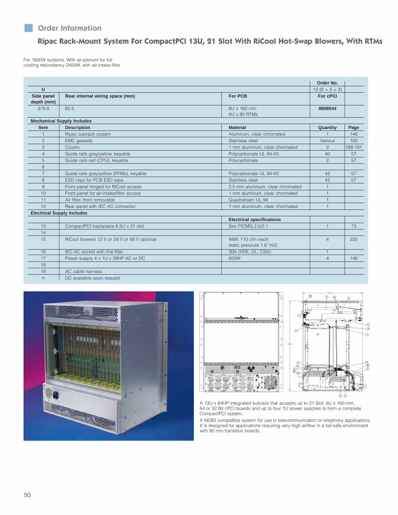
Ripac Rack-Mount System For CompactPCI 13U, 21 Slot With RiCool Hot-Swap Blowers, With RTMs
Order No.U 12 (6 + 3 + 3)
Side panel Rear internal wiring space (mm) For PCB For cPCIdepth (mm)
379.9 85.5 6U x 160 mm 98085446U x 80 RTMs
Mechanical Supply IncludesItem Description Material Quantity Page
1 Ripac subrack system Aluminum, clear chromated 1 1462 EMC gaskets Stainless steel Various 1003 Covers 1 mm aluminum, clear chromated 2 188-1914 Guide rails gray/yellow, keyable Polycarbonate UL 94-V0 40 575 Guide rails red (CPU), keyable Polycarbonate 2 5767 Guide rails gray/yellow (RTMs), keyable Polycarbonate UL 94-V0 42 578 ESD clips for PCB ESD wipe Stainless steel 42 579 Front panel hinged for RiCool access 2.5 mm aluminum, clear chromated 110 Front panel for air-intake/filter access 1 mm aluminum, clear chromated 111 Air filter, front removable Quadrafoam UL 94 112 Rear panel with IEC AC connector 1 mm aluminum, clear chromated 1
Electrical Supply IncludesElectrical specifications
13 CompactPCI backplane 6.5U x 21 slot See PICMG 2.0/2.1 1 731415 RiCool blowers 12 V or 24 V or 48 V optional 48W, 110 cfm each 4 222
static pressure 1.6" H2O16 IEC AC socket with line filter 30A (VDE, UL, CSA) 117 Power supply 4 x 1U x 28HP AC or DC 600W 4 1461819 AC cable harness DC available upon request
For 1800W systems. With air-plenum for fullcooling redundancy 2400W, with air-intake filter
Ripac Rack-Mounted System For CompactPCI 4U, 8 slots
A 13U x 84HP integrated subrack that accepts up to 21 Slot, 6U x 160 mm, 64 or 32 Bit cPCI boards and up to four 1U power supplies to form a completeCompactPCI system. A NEBS compatible system for use in telecommunication or telephony applications.It is designed for applications requiring very high airflow in a fail-safe environmentwith 80 mm transition boards.
Section 1_2-51 4/7/04 9:19 AM Page 51

51
Order Information Ripac Rack-Mount System For CompactPCI 13U, 21 Slot With RiCool Blowers, With RTMs
Technical Description:Vented system, 379.9 mm deep, forinstallation in 19" (486.2 mm) racks,cabinets or casesPrepared to accommodateCompactPCI boards and drives.Complies with IEC 60297-3/ -4/ -5-1xx;IEEE 1101.1/.10/.11
Features 12UPrepared for the installation of 21 x 6U x 160 mm cPCI front boards •and 21 x 6U x 80 mm RTMsFor the optional installation of drives and pluggable PSUs •6U x 8HP AC or DC power supplies, 2 x 350W included •Front/rear interface for CompactPCI defined injector/extractor handles •Keyable PCB guide/slot positions per PICMG 2.10 •Red guides for the system slot •Green guides for the PSU slot •Gray/yellow guides for peripheral slot identification •ESD clips for PCB ESD wipe •Optional ESD clips for front panel ESD protectionOptional 30A GND sockets for RTM protectionFront/rear cooling •EMC design •Forced air cooling with intelligent, hot-swap RiCool blowers •Fully wired and tested •
Options To Be Considered: For alternative cPCI backplanes,
see pages 73-78 For bridges, see page 83 For alternative cPCI/H.110
backplanes, see pages 74-95 For alternative PICMG 2.16 fabric
backplanes, see page 78 For alternative PICMG 2.17 star
fabric backplanes, see page 76
For alternative PSU backplanes, see pages 88-91
For power supplies, see page 91 For DC power entry module,
see page 92 For alarm board, see pages 93-94 For hard disk drive modules,
see page 95 For RiCool blowers,
see pages 222-225
For system thermal evaluation tools,see page 54
For EMC filler panels, see pages 208-209
For front panels and injector/extractorhandles, see page 98
For 30A RTM ground contacts, see page 58
Modification Service:Modifications or custom solutions areavailable. The Kaparel/Rittal systemspecialists will assist you with planning and configuration.
Section 1_2-51 4/7/04 9:19 AM Page 52

52
Order Information
Rack-Mount System For CompactPCI 10U, 21 Slot With RiCool Hot-Swap Blowers, With RTMs
For 500W+ systems. With air-plenum forfull cooling redundancy 700W, with air-intake filter
A NEBS compatible system for use intelecommunication or telephony applications. It is designed for applications requiring very high airflowin a fail-safe environment with 80 mmtransition boards.
Order No. ACU 10 (6 + 2 + 2)
Side panel Rear internal wiring space (mm) For PCB For cPCI recessed flange For cPCI front flangedepth (mm) gray black gray black
310 85.5 6U x 160 mm 9808039 9808038 9807773 98080286U x 80 RTMs
Mechanical Supply IncludesItem Description Material Quantity
1 Ripac subrack system Aluminum, zinc plated, painted 12 EMC gaskets Stainless steel Various3 All visible covers; Color: black; Inquire for options 1 mm steel, zinc plated, painted 24 Guide rails gray/yellow, keyable Polycarbonate UL 94-V0 385 Guide rails red (CPU), keyable Polycarbonate 26 Guide rails green (PSU), keyable Polycarbonate 27 Guide rails gray/yellow (RTMs), keyable Polycarbonate UL 94-V0 428 ESD clips for PCB ESD wipe Stainless steel 209 Front panel removable for RiCool access 1 mm steel, zinc plated, painted 110 Front panel for air-intake/filter access 1 mm steel 111 Air filter, front removable Quadrafoam UL 94 112 Rear panel with IEC AC/DC power entry 1 mm steel, painted 113 Display panel front, removable 1 mm steel, painted 114 19" mounting flanges, recessible 4" 2 mm steel, painted 2 2 – –15 19" mounting flange, front mount – – 2 2
Electrical Supply IncludesElectrical specifications
16 CompactPCI backplane 6.5U x 21 slot See PICMG 2.0/2.1 117 Power supply backplane for 2 x 8HP PSU See PICMG 2.11 118 RiCool blowers 12 V or 24 V or 48 V 48W, 110 cfm each 2
static pressure 1.6" H2O19 IEC AC socket with line filter 6A (VDE, UL, CSA) 120 Dual DC power entry with PEM Dual 48 V 121 Power supply 6U x 8HP AC or DC 350W each 122 LED display module with on/off switch +3.3 V, +5 V, +/-12 V fan failure 123 AC cable harness DC available upon request
13U CompactPCI-I System, with horizontally installed drives.
10U CompactPCI-I System, with horizontally installed drives.
12U CompactPCI-I System, with vertically installed drives.
12U CompactPCI-I System, withincreased air space and power supplyunit mounted in the base.
Section 2_52-103 4/6/04 4:26 PM Page 1

53
Order Information Compact-I Rack-Mount Shelf For CompactPCI 10U, 21 Slot With RiCool Blowers, With RTMs
Technical Description:Vented shelf, 310 mm deep, for installation in 19" (486.2 mm) racks,cabinets or casesPrepared to accommodateCompactPCI boards and drivesComplies with IEC 60297-3/ -4/ -5-1xx;IEEE 1101.1/.10/.11.
Features 10UPrepared for the installation of [?] x 6U x 160 mm cPCI front boards •and [?] 6U x 880 mm RTMs For the optional installation of drives and pluggable PSUs. •Optional 6U x 8HP AC or DC power supplies, 350W/450WFront/rear interface for CompactPCI defined injector/extractor handles •Keyable PCB guide/slot positions per PICMG 2.10 •Red guides for the system slot •Green guides for the PSU slot •Gray/yellow guides for peripheral slot identification •ESD clips for PCB ESD wipe •Optional ESD clips for front panel ESD protectionOptional 30A GND sockets for RTM protection •Powerful front to rear cooling •EMC design •Forced air cooling with intelligent, hot-swap RiCool blowers •Fully wired and tested •
Options To Be Considered: For alternative cPCI backplanes,
see pages 73-78 For bridges, see page 83 For alternative cPCI/H.110
backplanes, see pages 74-75 For alternative PICMG 2.16 fabric
backplanes, see page 78 Front or center mount flanges
available
For alternative PICMG 2.17 star fabric backplanes, see page 76
For alternative PSU backplanes, see pages 88-91
For power supplies, see page 91 For DC power entry module,
see page 92 For alarm board, see pages 93-94 For hard disk drive modules,
see page 95
For RiCool blowers, see page 222-225
For system thermal evaluation tools,see page 54
For EMC filler panels, see pages 208-209
For front panels and injector/extractorhandles, see page 98
For 30A RTM ground contacts, see page 58
The Compact-I system was specificallydeveloped for use in telecommunications,data communications and computertelephony applications. The design,based on a sheet steel outer enclosurewith a pull-out aluminum subrack; facilitates cost-effective mass production.As you would expect, all the requirementsof CompactPCI have been incorporatedinto the development. The basic variantsshown here are merely a selection of typical application examples, and can beconfigured to suit the customer’s specificrequirements. The systems are suppliedfully assembled and prewired includingbackplane and power supply unit.
Section 2_52-103 4/6/04 4:26 PM Page 2

CompactPCI System Cooling Analysis
n RiTherm n
The PS3900 Thermal Load Boards:The RiTherm load board is a conceptthat enables users to validate the thermal characteristics of their systembefore all PCBs are designed. In pastprojects, system designers have oftenunderestimated the need for heat dissipation. This miscalculation of thecooling system can cause costly problems, such as a missed productlaunch. Rittal and Kaparel havedesigned a simple system that willenable you to validate cooling dynamics of your particular systembefore it is built.
The PS6100 Thermal System:The RiTherm system consists of a 10UCompactPCI subrack equipped withtwo powerful hot swappable 12 VRiCool blowers. The cPCI backplaneis of your choice. The system shown isdesigned to accept up to 21 slots offront/rear mounted (6U x 160 mmfront/6U x 80 mm back) RiTherm loadboards simulating your actual cPCI boards.
Features: Simulation of I/O or SBC boards up
to 90W each Support up to 21 load boards Six temperature sensors on each
front load board
Three precision airflow sensors oneach load board
38 configurable resistor loads per6U x 160mm load board
No sensor wires required Uses the J1 connector of the
CompactPCI spec. for power only Uses the J5 connector for rear I/O
load board power interface The load boards will fit into any
IEEE 1101.10 compatible cPCIsystem or subrack
Simple Window user interface withgraphics and data logging
Daisy-chain RS232 port supported Low voltage detector description
Description:The RiTherm load board and theRiTherm system concept are builtaround the PS3900 load board. ThePS3900 load board is a 6U/3UCompactPCI form factor instrumenta-tion board and is cPCI based. It provides a resistive heating array, temperature and airflow sensors.
How To Order RiTherm:You can order either a completeRiTherm system consisting of theRiTherm subrack (chassis) with yourchoice of (No. of slots) cPCI backplane and (No. of) power supplies and drives or the individual
RiTherm PS3900 load boards to beplugged into your cPCI system. Whenordering a RiTherm system, you mustspecify the number of slots to be occupied by the load boards and thepluggable power supply (if used). For choice of cPCI backplanes, see our comprehensive range of cPCI backplanes.
Description Model Order No.10U RiTherm system w/o cPCI
PS3900 3687498backplane and PSU
Load board with airflow sensorsPS3901 36878266U x 160mm
Load board with airflow sensors, PS3903 36879876U x 80mm
Load board with airflow sensors, PS3904 36879883U x 160mm
Thermal accessory kit with software PS3902 3686886and cables
The PS3901 load board
54
Section 2_52-103 4/6/04 4:26 PM Page 3

55
The RiTherm Thermal Development System: Main WindowThe RiTherm Thermal Development System: Details Window
6U
10U
Air Out
Air Out
296.7mm
For PCB6U x 180
For PCB6U x 160
P5
P4
P3
P2
P1
Air In
Air In
Optional front removable
air filter
Air Suction To Cool Rear I/0
CompactPCI System Cooling Analysis RiTherm
PS3902 Thermal DevelopmentSoftware KTDS:Features: Main form plots temperature and
airflow outputs in a single GUI graphfor quick analysis
GUI board profile form displays provide exact temperature and airflow readings at each sensor,along with voltage levels
Board power form provides numberof loads per voltage on an individualboard basis
Can accommodate up to 42 boards
Main Components: 9 to 30 power resistor blanks that
can be individually powered fromeither the +5 V or the +3.3 V powerrails. These resistor banks are distributed evenly across the board,and can be configured to dissipate0-100W of combined power (maximum 40W from the +3.3 V rail,or 100W from the +5 V rail)
4 to 8 power resistor banks that canbe individually powered from eitherthe +12 V or the -12 V power rails,that can dissipate between 0W and23W of combined power
6 calibration-free temperature sensors, placed at various locations
8051 series microcontroller with aRS232C serial host interface. This interface is used to report temperature and airflow measurements to a host PC
Hot Swappable RiCool Blowers (2)
Section 2_52-103 4/6/04 4:26 PM Page 4

56
Airflow BlockersIn order to adequately and consistently cool cPCImodules and power supplies, unoccupied or emptyslots will have to be blocked as they are the majorcause for poor or inconsistent cooling. This is knownas the chimney effect.The airflow blocker is clipped over the installedmodule slot guide rail, preventing air to pass and atthe same time, preventing the insertion of a cPCImodule. The filler panel in turn is bolted in place ofthe cPCI module front panel, contributing to the con-trol of the system airflow and maintaining systemEMI integrity.
By not using an empty slot airflow managementdevice, the cooling efficiency of the cPCI systemmay reach such a reduced degree that cPCImodules stop functioning.The airflow blocker is designed for one 4 HP cPCImodule (160mm deep). The airflow blocker is notsuitable for the 1/2 HP offset power supply guiderail.
ConfigurationMaterial: Plastic UL 94-V0Color: Blue
CompactPCI Airflow Blocker
Description Compatible with Qty. required Qty. Order No.guide rail per slot
Airflow blocker 3684669 1 or 2 1 36879243686063 Top/bottom 1 3688055
System Filler PanelsFiller panels are used to cover unused slots as wellas to ensure intended airflow management,increase safety and prevent EMI emission.
There are two types of filler panels available: 3U and 6U non-EMC (flat w/o gasket) 3U and 6U EMC (U channel w/gasket)
ConfigurationMaterial: AluminumFinish: Chromated
Filler Panels Non-EMC
U Order No.4HP 8HP 12HP 16HP
3 3684891 3684895 3684897 36878296 3684913 3684917 3684919 3687830
Please order screws and retention sleeves separately:Order No. 3658160 (100 pcs. - slotted)Order No. 3684084 (100 pcs. + posidrive)
Filler Panels EMC
U Order No.4HP 8HP 12HP 16HP
3 3685178 3685182 3685184 36853736 3685186 3685190 3685192 3685453
Please order screws and retention sleeves separately:Order No. 3687050 (100 pcs. - slotted)Order No. 3687051 (100 pcs. + posidrive)
CompactPCI Subrack System DividerThis system divider splits 6U systems into 2 x 3Usections. Additional horizontal rails are mountedeither to the left or right side plates. Please state thearea to be divided, by placement (left or right) andby how many HP. Typically a CompactPCI frontpanel is 4HP wide, 4 x 5.08mm (0.2").
For other widths, please inquire.
Note: Horizontal dividing above 3 slots may requirea vertical support at a loss of one slot.
6U/2 x 3U System Divider Order No.4HP-1 slot 36878338HP-2 slots 3687834
12HP-3 slots 3687835
Keying Tool and KeysDescription Color Qty Order No.
Key Gray 100 3684325Key Red 100 3684326
Keying tool Yellow 1 3687956
Keys and programmable keying tool®
Accessories
n RiTherm n
Section 2_52-103 4/6/04 4:26 PM Page 5

57
CompactPCI Module Guide Rails
Description Position Color Offset Retention ESD clip ESD clip Earth/GND* Keying* Qty req. QtyOrder No.used for slot 1/2HP screw PCB front panel contact pegs for 1 cPCI
required available available available available moduleSystem Top/bottom Red No Optional Yes Yes - Yes 2 1 3686063
Peripheral Top/bottom Gray No Optional Yes Yes - Yes 2 1 3684669Rear I/O Top Gray No *M3.5 x 10 Yes - Yes Yes 1 1 3687936Rear I/O Bottom Gray No *M3.5 x 10 Yes - Yes Yes 1 1 3687937
PSU 38 pin Top/bottom Gray No Optional Yes Yes - Yes 2 1 3684669PSU 38 pin Top/bottom Green No Optional Yes Yes - Yes 2 1 3688055PSU 47 pin Top/bottom Green Yes Optional Yes Yes - Yes 2 1 3687832
Note: For earth/ground contact, see page 11. For keying, see page 10 and page 63 of the CompactPCI catalog.* For Torx T-10 compatible drive bits.
The PICMG 2.0 specification onlymakes reference in chapter 4.1.10 tothe system slot identification (guiderails) by defining the color red to identify CPU system slots. All otherslot positions (guide rails) can be ofany other color than red. Additionallythe PICMG 2.11 specification definesin chapter 3.2 a that the pluggablepower supply (PSU) guide rails haveto provide for a 1/2 HP offset and shall
Optional CompactPCI Guide Rail PartsDescription Qty. required for 1 Qty. Order No.
CompactPCI moduleESD clip, PCB 1 or 2 50 3684204ESD clip, front panel 1 or 2 50 3684205Earth/ground contact 1 50 3687951*Retention screw M3.5 x 10 for rear I/O guide rail with or 2 50 3684109without earth/ground contactRetention screw, optional 4 100 3654360Keying pegs, red 1 to 6 100 3684326Keying pegs, gray 1 to 6 100 3684325
* For Torx T-10 compatible drive bits.
For System/Peripheral/Power Supply Slots CompactPCI PCB Guide Rails
be green in color. However, PICMG2.11 defines in appendix B that theexisting practice of using any colorguide rail with (no offset) is alsoacceptable practice for the 38 pin in-rack power supply connector.PICMG2.0 refers in chapter 4.2.1 to the rearI/O guide rails.Material: Plastic UL 94-VO
Section 2_52-103 4/6/04 4:26 PM Page 6

58
The PICMG Telecom InterestSubcommittee (TISC) requested thatIEEE 1101.11 provide a means forallowing the CompactPCI rear I/Omodule front panel to be at protectiveearth potential when fully inserted inthe cPCI system.Typically, rear I/O panels were of a single, monolithic rear panel design –usually hard wired with an earth/ground connection the chassisearth/ground. With the large number of 6U cPCI backplane I/O pins, cPCIrear I/O modules (managing rear I/Owiring/interfaces) are designed to the same modularity and fast interchangeability as the front mounted cPCI active modules.
Note: Typically the earth/ground contact is only necessary in the bottomposition of the subrack/module. This requires one bottom guide I/O rail, oneearth/ground contact and receptacle and one retention screw. The uppersubrack/module position typically requires only one top I/O guide rail andone retention screw. The 160 mm guide rail adapter is only being used ifearth/ground contact is required for system front mounted (160 mm deep)cPCI modules.
If each individual rear I/O module would be earth/ground hard wired witha traditional earth/ground connection,there would be possibly no spaceavailable on the I/O module frontpanel, and in practice this wouldbecome an unmanageable situation.This is why PICMG - TISC required an alternative solution.IEEE 1101.11 defines in chapter 15that the mechanical and electricalrequirements for this type of “pluggable” earth/ground contactshould be only one componenttowards providing earthing/groundingof a complete system. Separately,Kaparel/Rittal submitted their earth/ground contact design (in accordance
For Rear cPCI I/O Modules
Ground Connections n
with IEEE 1101.11) to UL for UL 1950recognition testing (30A).The UL recognized test has beenundertaken with a single earth/groundcontact per rear I/O module only. If theearth/ground contact is present, therear cPCI I/O module front panel ESDclip mounted into the guide rail is notrequired. However, the PCB ESD clip inthe guide rail may still be required towipe the ESD of the I/O module PCBduring insertion.The design of the 80 mm I/O guide railpermits the use of this earth/ groundfeature as a 160 mm guide for frontmounted cPCI modules as well, simply connecting one left hand andone right hand 80 mm guide with aguide rail adapter.
Configuration:cPCI Specifications: PICMG 2.0 (3.6.1 a)
Material: Handle/PCB holders with
earth/ground pin: zinc alloy die-casting, nickel plated (not part of the delivery)
Earth/ground receptacle: zinc alloydie-casting, tin plated
Earth/ground contact: berylliumcopper, silver plated
Assembly screw: M3.5 x 10 hardened steel, chromated
Note: This screw has a Torx feature and requires a Torx T-10 compatibledrive bit.
Earthing/Grounding Connections
Description Qty. Order No.Guide rail I/O - 80 mm top, gray 1 3687936
Guide rail I/O - 80 mm bottom, gray 1 3687937Earth/ground contact and receptacle 50 3687951
Retention screw 50 3684109Guide rail adapter for 160 mm 1 3684110
Section 2_52-103 4/6/04 4:26 PM Page 7

59
A fully connector loaded 6U cPCImodule requires approximately 118lbs./525N force to be inserted into a fully connector loaded cPCI backplane. The safe mating area ofthe 2 mm cPCI connector pin is as little as .078" (2.00 mm). At the same time, the module into subrackassembly permits only a maximum tolerance of plus/minus .035" (0.9 mm)and the backplane bow must be calculated within this plus/minus tolerance (see IEEE 1101.1 chapter11, 8). This requires tremendous atten-tion to mechanical detail and confor-mance to specification when design-ing a cPCI system.
While larger slot count cPCI 6U backplanes may be rigid enough to counter the 118 lbs. force wheninjecting/extracting a cPCI modulefrom the system, certainly the lesserslot width 6U backplanes will bow,resulting in poor interconnection.
For such situations Kaparel/Rittal hasdesigned a backplane stiffener for itscPCI backplane range. Tests haveproven that the backplane flex can bereduced by as much as 70% (6U x 3slot) on Kaparel/Rittal’s 6U cPCI back-planes at a backplane thickness of0.14" (3.5 mm).
cPCI 6U Backplane Stiffener
Description Qty. Order No.Backplane stiffener kit - 6U 1 3688088
This Kaparel/Rittal cPCI backplanestiffener can be retrofitted to allKaparel/Rittal cPCI PS backplaneswithout any physical change to thebackplane itself, permitting full use ofthe backplane front mounted and rearmounted cPCI modules.
Configuration: Backplane stiffener Backplane stiffener to backplane
mounting screw - 5 pcs. Spacer A - 1 piece (used for
non-backplane through hole attachment)
Spacer B - 1 piece (used for backplane through hole attachment)
Material: Extruded aluminum
Reduce Unwanted Backplane Bow Backplane Stiffeners
Section 2_52-103 4/6/04 4:26 PM Page 8

Modular CompactPCI BackplanesModular CompactPCI And Switched Fabric Backplanes Compreh
Product Diversity Knowledge Transfer MPS Expertise Globalization Integrative Thinking
60
Section 2_52-103 4/6/04 4:34 PM Page 9

Let Kaparel/Rittal Back You Up.As you can see, there is nothing conventional about Kaparel/Rittal. And our backplanes are no exception. We offer a comprehensive family of modular CompactPCI 3U and 6U backplanes, with an added 1/2U for efficient power management. What’s more, this unique range of backplanesincludes 32-bit and 64-bit versions, family related and electronicallymatched bridges, cables, power supply backplanes and CompactPCI plus H.110 backplanes. It’s exactly what you would expect fromKaparel/Rittal-the Original CompactPCI Packaging Company.
Kaparel/Rittal RipacCompactPCI Backplanes Technical
Bridging Beyond Eight Slots . . . . . . . . . . . . . . . . . . . . . . . . . . . . . . .64
6U, 6.5U, and 7U Configurations . . . . . . . . . . . . . . . . . . . . . . . . . . . .66
CompactPCI, H.110, and Fabric Pinouts . . . . . . . . . . . . . . . . . . . .66-67
CompactPCI Choice of Backplanes
Modular Applications . . . . . . . . . . . . . . . . . . . . . . . . . . . . . . . . . . . . .70
Modular Series Combination Tables . . . . . . . . . . . . . . . . . . . . . . . . . .71
PS1300 3U Series . . . . . . . . . . . . . . . . . . . . . . . . . . . . . . . . . . . . . . .72
PS1400 and PS1400B 6U Series . . . . . . . . . . . . . . . . . . . . . . . . . . . .73
PS4400 6U Compact PCI/H.110 Series . . . . . . . . . . . . . . . . . . . . . . .74
PS4400B 6U CompactPCI/H.110 Series . . . . . . . . . . . . . . . . . . . . . . .75
PS1410B and PS4410B 6U Backplanes . . . . . . . . . . . . . . . . . . . . . . .73
Custom Applications . . . . . . . . . . . . . . . . . . . . . . . . . . . . . . . . . . . . .82
PS4800 Series 2.17 Backplanes . . . . . . . . . . . . . . . . . . . . . . . . . . . .76
PS4900 Series 2.16 Backplanes . . . . . . . . . . . . . . . . . . . . . . . . . . . .79
23000 Series PXI Backplanes . . . . . . . . . . . . . . . . . . . . . . . . . . . . . .80
CompactPCI Bridge Modules
3U and 6U Front Bridges . . . . . . . . . . . . . . . . . . . . . . . . . . . . . . . . . .64
PS111x and PS112x Rear Pallet Bridges . . . . . . . . . . . . . . . . . . . . . .82
PS1130 Rear Pallet Bridge . . . . . . . . . . . . . . . . . . . . . . . . . . . . . . . . .83
32-bit Low Profile Bridges . . . . . . . . . . . . . . . . . . . . . . . . . . . . . . . . .84
64-bit Low Profile Bridges . . . . . . . . . . . . . . . . . . . . . . . . . . . . . . . . .85
PS1150 H.110 Bridges . . . . . . . . . . . . . . . . . . . . . . . . . . . . . . . . . . .86
Powering CompactPCI
3U Power Supply Backplanes . . . . . . . . . . . . . . . . . . . . . . . . . . . . . .88
6U x 8HP Power Supply Backplanes . . . . . . . . . . . . . . . . . . . . . . . . .89
6U x 16HP Power Supply Backplanes . . . . . . . . . . . . . . . . . . . . . . . .90
3U Power Supplies . . . . . . . . . . . . . . . . . . . . . . . . . . . . . . . . . . . . .142
6U Power Supplies . . . . . . . . . . . . . . . . . . . . . . . . . . . . . . . . . . . . .143
Power Entry Modules (PEMs) . . . . . . . . . . . . . . . . . . . . . . . . . . . . . . .87
Auxiliary Products
System Management: Alarm Boards . . . . . . . . . . . . . . . . . . . . . . . . .93
CompactPCI-SCSI HDD Modules . . . . . . . . . . . . . . . . . . . . . . . . . . .95
hensive Solutions
CompactPCI
Comprehensive Solutions
Backplanes
61
Section 2_52-103 4/6/04 4:34 PM Page 10

62
Overview Of Backplanes
CompactPCI
CompactPCI Backplanes
3.5/6.5U, 2 – 8 slotsOrder No. see page 72
ApplicationsInstallation in CompactPCI computer systemsfor power and signal distribution for plug-inboards and assemblies, e.g. for Telecommunications Automation
Design Features Fiberglass epoxy to DIN 40 802 (type FR 4) 3.5U and 6.5U, 2-8 slots 32 bit/64 bit 8 layer multi-layer System slot on right Voltage supply via ATX-compatible
connectors
User Benefits High-speed backplane Extendible to a maximum of 21 slots via
bridge modules Complies with PCI 2.1 and PICMG 2.0
(CompactPCI spec.)
Switch Fabric Backplanes
7U, Switch Fabric PICMG 2.16, PICMG 2.17Order No. see pages 78-79
User Benefits High-speed backplane H.110 bus optional Up to 21 slots Hot swap-compatible Supports Ethernet Conforms to PCI 2.1, PICMG 2.0
(CompactPCI Spec.), PICMG 2.1 (hot swap), PICMG 2.5 (CCI ComputerTelephony), PICMG 2.16
CompactPCI Backplanes
7U with H.110Order No. see pages 74-75
User Benefits High-speed backplane Including H.110 bus Extendible to a maximum of 21 slots via
jumper modules Hot swap-compatible Conforms to PCI 2.1, PICMG 2.0
(CompactPCI Spec.), PICMG 2.1 (hot swap), PICMG 2.5 (CCI ComputerTelephony)
ApplicationsInstallation in CompactPCI computer systems for power and signal distribution forplug-in boards and assemblies, e.g. for Telecommunications Computer telephony Automation
Design Features Fiberglass epoxy to DIN 40 802 (type FR 4) 7U, 3-8 slots 32/64 bit (for CompactPCI) Including H.110 bus 8 layer multi-layer System slot on right Voltage supply via ATX-compatible
connectors
ApplicationsInstallation in CompactPCI computer systemsfor power and signal distribution for plug-inboards and assemblies, e.g. for Telecommunications Computer telephony
Design Features Fiberglass epoxy to DIN 40 802 (type FR 4) 6U/7U, 8, 16, 21 slots 64 bit (for CompactPCI) Optionally including H.110 bus For plug-type cPCI power supply units
Section 2_52-103 4/6/04 4:34 PM Page 11

63
Overview Of Backplanes CompactPCI
CompactPCI Bridge
CompactPCI Bridge/Low Profile BridgeOrder No. see page 83
ApplicationsCompactPCI bridge to extend the bus by up to nx7 additional slots in each case. Connectsthe CompactPCI backplanes 3.5 and 6.5U and handles all communications between theindividual bus segments.
User Benefits Bus extension by up to 7 additional slots Supports the 64 bit PCI bus Complies with PCI 2.1, CompactPCI 2.1 Low profile bridge without loss of slots
cPCI Power Supply Backplane
6.5U, 8 and 16 HPOrder No. see pages 87-90
User Benefits Accommodates one or two power supply
units (up to 500W) Complies with PICMG 2.0, PICMG 2.11
cPCI Power Supply Backplane
3.5U, 16 HPOrder No. see page 86
User Benefits Accommodates a maximum of two
power supply units (up to 250W) The second power supply unit can be
used for redundancy or to increase the current
Complies with PICMG 2.0, PICMG 2.11
ApplicationsBackplane to accommodate a maximum oftwo power supply units up to 250W in conjunction with CompactPCI backplane3.5U and 6.5U.
ApplicationsBackplanes to accommodate a maximum oftwo power supply units up to 500W in conjunction with CompactPCI backplanes3.5U, 6.5U and H.110.
Design Features Fiberglass epoxy to DIN 40 802 (type FR 4) May be connected to the rear of
CompactPCI backplanes 64 bit DEC 21 15 Low profile bridge for 32 and 64 bits
Low Profile Design
Design Features Fiberglass epoxy to DIN 40 802
(type FR 4) 3.5U, 16HP Accommodates a maximum of two power
supply units (up to 250W) Voltage supply via ATX-compatible
connectors
Design Features Fiberglass epoxy to DIN 40 802 (type FR 4) 6.5U, 8 and 16HP Accommodates one or two power supply
units (up to 500W) Voltage supply via ATX-compatible
connectors
Section 2_52-103 4/6/04 4:34 PM Page 12

64
General CompactPCI Backplane Information
Bridging Beyond Eight Slots
Figure 1 Figure 2 Figure 3
As a pioneer in CompactPCIKaparel/Rittal was the first company todevelop bridging techniques and takesystems beyond 8 slots on a given bussegment, as defined in the PICMG 2.0Specification. This restriction has beendetermined through extensive simulation and characterization andguarantees operation of PCI compliantICs within a 33 MHz CompactPCI bussystem. This slot count restriction canbe overcome by using bridges.A bridge is a device that connects totwo buses and provides a bi-directionaldata path between them. Bridges canconnect between two dissimilar buses(e.g. PCI to ISA) or between buses ofthe same type (PCI to PCI). This following describes CompactPCI toCompactPCI bridges. (See Figure 1.)A CompactPCI bridge attaches to twobus segments and connects them tocreate one single logical bus. The segment on which the system host controller resides is called the “primary”bus, and the other is the “secondary”bus. The bridge device acts as systemhost for the secondary bus segment.The bridge allows full addressing andcommunication access betweendevices on either segment. Bridges can be cascaded to create longer bus configurations.CompactPCI bridges used to extendbeyond 8 slots can be divided into twocategories: integrated and stand-alone.An integrated bridge is part of a specialized single board computer(SBC) board designed to host two bussegments. Several vendors offer thesetypes of SBC boards. The two mostcommon implementations are single-slot and dual-slot. (See Figure 2.)Single-slot dual-bus SBCs host their pri-mary CompactPCI bus on connectorsJ1 and J2 and host the secondary, orbridged, segment on connectors J4and J5 of the same slot. Specializedbackplanes are required to supportthese boards, and the secondary bussegment will be limited to fewer than 8slots to compensate for the non-standardbus routing to the host’s J4 and J5 connectors. Simulation may be necessary. (See Figure 3.)
Dual-slot dual-bus SBCs use two“stacked” boards to span across twoadjacent backplane slots. Thesedevices also require specialized backplane designs, but no special routing is required.Stand-alone bridges are not part of anySBC board. They are dedicateddevices for extending CompactPCIbuses beyond 8 slots. It is important tonote that CompactPCI systems are limited to 8 slots including the bridge.Stand-alone bridges occupy one logical slot on each of the primary andsecondary PCI segments, limiting thenumber of usable slots to 7 on eachbus segment. Kaparel/Rittal offersstand-alone bridges in several styles asdescribed below:
Single-slot Front Bridges:Single-slot front bridges have a standard CompactPCI mechanical formfactor. These bridges connect two segments “vertically” within a singleCompactPCI slot. Specialized backplanes are required to supportthese bridges, and the secondary bussegment may be limited to fewer than 8 slots to compensate for the non-standard bus routing to the bridge’ssecondary bus connector.Kaparel/Rittal’s line of single-slot frontbridges includes the PS1100 andPS1101 – 6U and 3U 32-bit bridgesconnecting to a primary CompactPCIbus on connector J1 and a secondaryCompactPCI bus on connector J2, andthe PS1100 – a 6U 64-bit bridge connecting to a primary CompactPCIbus on connector J1/J2 and a secondaryCompactPCI bus on connector J4/J5.
Dual-slot Rear Bridges:Rear-mount pallet bridges were developed by Kaparel/Rittal to allowmultiple CompactPCI segments to bebridged without sacrificing valuablefront slots. These bridges allow allavailable slots in a system to be usedfor CompactPCI host and peripheral boards.
Order No. DescriptionPS1100 Front board 6U 32 bit CompactPCI bridgePS1101 Front board 3U 32 bit CompactPCI bridge
Section 2_52-103 4/6/04 4:34 PM Page 13

65
specifications are still in the developmentstate or have yet to be ratified asdefacto standards. In order to keeptime-to-market to a minimum thedeployment of Switched Fabrics isbeing leveraged by using existingproduct offerings. This results in transitional systems where legacyCompactPCI© components coexist withSwitch Fabric components.Kaparel/Rittal has introduced methodsof bridging legacy CompactPCI©
components into a Switch Fabric environment to the market includingthe first PICMG 2.16 Ethernet backplaneas well as others like StarFabric andPLX Gigabridge. As an ExecutiveMember of PICMG we constantly striveto offer products to the market utilizingthe latest proven technologies to provide fast-to-market high availabilityand redundancy solutions.
These devices are attached to the rearof the backplane using dedicatedhigh-density connectors, and are significantly smaller and shallower than other pallet bridges, eliminatinginterference with other devices.Kaparel/Rittal’s low-profile bridge family consists of the PS1131 and PS1132,32-bit and 64-bit bridges for systemswith a left-side primary bus and right-side secondary bus, and thePS1133 and PS1134, 32-bit and 64-bitbridges for systems with a right-sideprimary bus and left-side secondarybus. Kaparel/Rittal’s new PS1400B and PS4400B series of modular backplanes are designed for use with low-profile bridges.All CompactPCI bridges used forextending systems beyond 8 slots willrequire backplanes specially designedfor their use. All of Kaparel/Rittal’sbridges and bridgeable backplaneswere designed in tandem to ensure fullinteroperability and reliable functionality.
Switch Fabric Bridges:As the telecom industry moves to thenew Switched Fabric architectures, it brings the promise of true high availability (HA) and redundancy tosystem design. One of the limitationsof current solutions is the fact that moststill limit designers to a maximum of 2system controllers which must reside inthe same chassis. Switched Fabrics onthe other hand, have relatively littlerestrictions on system architecture.The deployment of pure SwitchedFabric systems in the industry is progressing and many of the
Pallet bridges attach to transition-style feed-through connectors on the rear of the backplane, and are oriented parallel to the backplane, spanningseveral slots. One advantage of palletbridges is that they can be used tobridge between physically separatebackplanes, allowing for a modularapproach to CompactPCI systemdesign. Kaparel/Rittal's family of palletbridge products includes the PS1111and PS1112 32-bit bridges, PS1121and PS1122 64-bit bridges, and thePS1130 – a 64-bit pallet bridge specially designed for use withKaparel/Rittal’s PS1300, PS1400 and PS4400 modular series of CompactPCI backplanes.
Low Profile Rear Bridges:Pallet bridges offer several advantagesover front slot bridges, but can interferemechanically with rear transition boardsin some systems. This interference canoften be overcome by modifying thetransition boards’ mechanical design, butfor instances where this is impossible orundesirable Kaparel/Rittal developed aseries of low-profile pallet bridges.
Backplane Solutions For CompactPCI Applications Bridging Beyond Eight Slots
Rear
<16
mm
Front
low profilerear bridge
modularbackplane
The StarFabric Developer logo is a registered trademark of the StarFabric Trade Association. All rights reserved.
The Low Profile AdvantageTotal Profile <16 mm:Kaparel/Rittal’s PS1131-PS1134 offer allthe functionality of our regular profilerear pallet bridges, but with a total profile of <16 mm to the highest component, enabling the use of off-the-shelf rear transition modules, with full IEEE 1101.11 compliance.
Section 2_52-103 4/6/04 4:34 PM Page 14

66
6U and 6.5U CompactPCIBackplanes:Although listed as 6U (233.35 mm),Kaparel/Rittal’s PS1400 series modularbackplanes (see page 73) are actually6.5U (284.15 mm) tall. This extra 0.5Uallows for a better selection of reliablepower connectors. Certain models ofthe power backplanes (see pages 88-91), which are perforated at the 6U mark, may be used in an exact 6U form factor, depending on the particular configuration.
7U CompactPCI/H.110Backplanes:Kaparel/Rittal’s PS4400 modular seriesCompactPCI/ H.110 backplanes (seepages 74-75) are 7U (304.8 mm) tall.As with the PS1400 series, the initial0.5U (bringing the board to 6.5U)allows for a better selection of reliablepower connectors. The second 0.5U(bringing the board to 7U) acts as anairflow baffle at the bottom of the subrack. This enables airflow up theentire length of the front modules, providing greater cooling capacity, and improved system performance.
PS4400 Series Slot Pinouts:In all members of Kaparel/Rittal’sCompactPCI/H.110 backplanes, thePS4400 series (see page 67), there arefive different pinouts for CompactPCIbus connectors (see page 68 forH.110 pinouts). These five pinout designations correspond to differentarrangements and applications of the64-bit or 32-bit CompactPCI bus. AllPS4400 backplanes (and PS4461) useH2 (64-bit host), P2 (64-bit peripheral)and/or B2 (64-bit bridge/peripheral)
H=host P=peripheral 1=32-bit 2=64-bit
Order No. Model No. Slot No.1 2 3 4 5 6 7 8
3686877 PS4400 P2 P2 P2 P2 P2 P2 P2 H23687876 PS4401 P1 H13687873 PS4420 P2 P2 P2 B2 P2 P2 H2 3687877 PS4421 P1 H1 3687874 PS4430 P2 P2 P2 B2 P2 H23687878 PS4431 P1 H1 3687875 PS4440 P2 P2 P2 P2 H23687879 PS4441 P1 H13688507 PS4450 P2 P2 P2 H23688508 PS4460 P2 P2 H23688623 PS4462 P2 H2
pinouts. All other backplanes use H1(32-bit host) and P1 (32-bit peripheral)pinouts. Descriptions of the variousdesignation types are listed below, aswell as along side their respective pinouttables on the following pages (66-69).
Slot Designations:CompactPCI Peripheral Slot (6U Slot):These are 64-bit peripheral slots.BD_SEL# and 64EN# are connected to GND. Pins labeled N/C are not con-nected to anything by the backplane*†
CompactPCI H.110 Slot (P4/J4):All members of the PS4400 series support an H.110 Computer Telephonybus on J4 of all slots. This bus can beextended to up to 21 slots using variousbridge modules (standard pallet or low profile). J5 is loaded with long-tailconnectors for I/O on the rear of the backplane.
CompactPCI Standard Fabric Slot (P3/P5):These slots support nineteen (19) linkports that are uniquely linked to/fromeach node slot. Fabric slots are intended to accept fabric boards.
CompactPCI Extended Fabric Slot (P4):These slots support twenty-four (24)link ports that are uniquely linkedto/from each node slot. Extended fabric slots are intended to accept fabric boards.
General CompactPCI Backplane Information
6U/6.5U/7U Configurations nPin Assignments:At the connector level, pin columns arelabeled left-to-right: Z, A, B, C, D, E, F.Pin rows are labeled from the bottomup:1, 2, 3 etc., to 19 (J3), 22 (J2, J5),or 25 (J1, J4).
Section 2_52-103 4/6/04 4:34 PM Page 15

67
CompactPCI Host Slot P1 and P2 Pinout:These are 64-bit host slots. Host signals ( CLK[n],REQ#[n] and GNT#[n] ) are on J2.
Row ColumnZ A B C D E F
22 GND GA4 GA3 GA2 GA1 GA0 GND
21 GND CLK6 GND N/C N/C N/C GND
20 GND CLK5 GND N/C GND N/C GND
19 GND GND GND N/C N/C SMB_ALERT# GND
18 GND BRSVP2A18 BRSVP2B18 BRSVP2C18 GND BRSVP2E18 GND
17 GND BRSVP2A17 GND PRST# N/C N/C GND
16 GND BRSVP2A16 BRSVP2B16 DEG# (1) GND BRSVP2E16 GND
15 GND BRSVP2A15 GND FAL# (1) N/C N/C GND
14 GND AD[35] AD[34] AD[33] GND AD[32] GND
13 GND AD[38] GND VIO AD[37] AD[36] GND
12 GND AD[42] AD[41] AD[40] GND AD[39] GND
11 GND AD[45] GND VIO AD[44] AD[43] GND
10 GND AD[49] AD[48] AD[47] GND AD[46] GND
9 GND AD[52] GND VIO AD[51] AD[50] GND
8 GND AD[56] AD[55] AD[54] GND AD[53] GND
7 GND AD[59] GND VIO AD[58] AD[57] GND
6 GND AD[63] AD[62] AD[61] GND AD[60] GND
5 GND C/BE[5]# GND VIO C/BE[4]# PAR64 GND
4 GND VIO BRSVP2B4 C/BE[7]# GND C/BE[6]# GND
3 GND N/C GND N/C N/C N/C GND
2 GND N/C N/C GND GNT2# N/C GND
1 GND CLK1 GND REQ1# GNT1# REQ2# GND
25 GND +5V REQ64# ENUM# +3.3V +5V GND
24 GND AD[1] +5V VIO** AD[0] ACK64# GND
23 GND +3.3V AD[4] AD[3] +5V** AD[2] GND
22 GND AD[7] GND +3.3V** AD[6] AD[5] GND
21 GND +3.3V AD[9] AD[8] M66EN C/BE[0]# GND
20 GND AD[12] GND VIO AD[11] AD[10] GND
19 GND +3.3V AD[15] AD[14] GND** AD[13] GND
18 GND SERR# GND +3.3V PAR C/BE[1]# GND
17 GND +3.3V IPMB_SCL IPMB_SDA GND** PERR# GND
16 GND DEVSEL# GND VIO STOP# LOCK# GND
15 GND +3.3V FRAME# IRDY# GND* TRDY# GND
1413 KEY12
11 GND AD[18] AD[17] AD[16] GND** C/BE[2]# GND
10 GND AD[21] GND +3.3V AD[20] AD[19] GND
9 GND C/BE[3]# GND* AD[23] GND** AD[22] GND
8 GND AD[26] GND VIO AD[25] AD[24] GND
7 GND AD[30] AD[29] AD[28] GND** AD[27] GND
6 GND REQ0# PCI_PRESENT# +3.3V CLK0 AD[31] GND
5 GND BRSVP1A5 BRSVP1B5 RST# GND** GNT0# GND
4 GND IPMB_PWR HEALTHY# VIO INTP INTS GND
3 GND INTA# INTB# INTC# +5V** INTD# GND
2 GND TCK +5V TMS N/C N/C GND
1 GND +5V -12V TRST# +12V +5V GND
General CompactPCI Backplane Information PS4400 Series CompactPCI Pinouts
NB- Rear tail length of pins dependent upon slot configuration. Please see PICMG 2.5, or email [email protected] for details.Table Legend:short pins
medium pinslong pins
J2/P
2J1
/P1
Section 2_52-103 4/6/04 4:34 PM Page 16

68
General CompactPCI Backplane Information
PS4400 Series CompactPCI Pinouts
NB- Rear tail length of pins dependent upon slot configuration please see PICMG 2.5, or email [email protected] for details.Table Legend:short pins
medium pinslong pins
Row Column
Z(14) A B C D E F(9)
22 GND GA4(13) GA3(13) GA2(13) GA1(13) GA0 GND
21 GND RSV RSV RSV RSV RSV GND
20 GND RSV RSV RSV GND RSV GND
19 GND RSV RSV RSV RSV RSV GND
18 GND BRSVP2A18 BRSVP2B18 BRSVP2C18 GND BRSVP2E18 GND
17 GND BRSVP2A17 GND RSV RSV RSV GND
16 GND BRSVP2A16 BRSVP2B16 RSV GND BRSVP2E16 GND
15 GND BRSVP2A15 GND RSV RSV RSV GND
14 GND AD[35] AD[34] AD[33] GND AD[32] GND
13 GND AD[38] GND V(I/O)(2) AD[37] AD[36] GND
12 GND AD[42] AD[41] AD[40] GND AD[39] GND
11 GND AD[45] GND V(I/O)(2) AD[44] AD[43] GND
10 GND AD[49] AD[48] AD[47] GND AD[46] GND
9 GND AD[52] GND V(I/O)(2) AD[51] AD[50] GND
8 GND AD[56] AD[55] AD[54] GND AD[53] GND
7 GND AD[59] GND V(I/O)(2) AD[58] AD[57] GND
6 GND AD[63] AD[62] AD[61] GND AD[60] GND
5 GND C/BE[5]# GND V(I/O)(2) C/BE[4]# PAR64 GND
4 GND V(I/O)(2) BRSVP2B4 C/BE[7]# GND C/BE[6]# GND
3(3) GND RSV GND RSV RSV RSV GND
2(3) GND RSV RSV UNC(4) RSV RSV GND
1(3) GND RSV GND RSV RSV RSV GND
25 GND 5V REQ64# ENUM# 3.3V 5V GND
24 GND AD[1] 5V V(I/O)(2)1 AD[0] ACK64# GND
23 GND 3.3V AD[4] AD[3] 5V AD[2] GND
22 GND AD[7] GND 3.3V AD[6] AD[5] GND
21 GND 3.3V AD[9] AD[8] M66EN(6) C/BE[0]# GND
20 GND AD[12] GND V(I/O)(2) AD[11] AD[10] GND
19 GND 3.3V AD[15] AD[14] GND AD[13] GND
18 GND SERR# GND 3.3V PAR C/BE[1]# GND
17 GND 3.3V IPMB_SCL IPMB_SDA GND PERR# GND
16 GND DEVSEL# GND V(I/O)(2) STOP# LOCK# GND
15 GND 3.3V FRAME# IRDY# BD_SEL#(7) TRDY# GND
1413 KEY12
11 GND AD[18] AD[17] AD[16] GND C/BE[2]# GND
10 GND AD[21] GND 3.3V AD[20] AD[19] GND
9 GND C/BE[3]# IDSEL(7) AD[23] GND AD[22] GND
8 GND AD[26] GND V(I/O)(2) AD[25] AD[24] GND
7 GND AD[30] AD[29] AD[28] GND AD[27] GND
6 GND REQ# GND 3.3V CLK AD[31] GND
5 GND BRSVP1A5 BRSVP1B5 RST# GND GNT# GND
4 GND IPMB_PWR HEALTHY#(18) V(I/O)(2) INTP INTS GND
3 GND INTA# INTB# INTC# 5V INTD# GND
2 GND TCK(15) 5V TMS(15) TDO(15) TD(15) GND
1 GND 5V -12V TRST#(15) +12V 5V GND
CompactPCI Peripheral Slot P1 and P2 Pinout:These are 64-bit peripheral slots. BD_SEL# and 64EN# areconnected to GND.
J2/P
2
CompactPCI H.110 (P4) Pinout:All members of the PS4400 series support an H.110Computer Telephony bus on J4 of all slots. This bus can be extended to up to 21 slots using various bridge modules (standard pallet or low profile). J5 isloaded with long-tail connectors for I/O on the rear of the backplane.
Row Column
Z A B C D E F
25 GND SGA4 SGA3 SGA2 SGA1 SGA0 GND
24 GND GA4 GA3 GA2** GA1 GA0 GND
23 GND +12V CT_RESET# (4) CT_EN# -12V** CT_MC GND
22 GND PFS0# (3) N/C N/C** N/C RSVD GND
21 GND -SELVbat PFS1# (3) N/C N/C SELVbatRtn GND
20 GND NP (1) NP (1) NP (1) NP (1) NP (1) GND
19 GND NP (1) NP (1) NP (1) NP (1)** NP (1) GND
18 GND VRG (3) NP (1) NP (1) NP (1) VRGRtn GND
17 GND NP (1) NP (1) NP (1) NP (1)** NP (1) GND
16 GND NP (1) NP (1) NP (1) NP (1) NP (1) GND
15 GND -Vbat NP (1) NP (1) NP (1)* VbatRtn GND
1413 KEY12
11 GND CT_D29 CT_D30 CT_D31 V(I/O)** CT_FRAME_A# GND
10 GND CT_D27 +3.3V CT_D28 +5V CT_FRAME_B# GND
9 GND CT_D24 CT_D25* CT_D26 GND** FR_COMP# GND
8 GND CT_D21 CT_D22 CT_D23 +5V CT_C8_A GND
7 GND CT_D19 +5V CT_D20 GND** CT_C8_B GND
6 GND CT_D16 CT_D17 CT_D18 GND CT_NETREF_1 GND
5 GND CT_D13 CT_D14 CT_D15 +3.3V** CT_NETREF_2 GND
4 GND CT_D11 +5V CT_D12 +3.3V SCLK GND
3 GND CT_D8 CT_D9 CT_D10 GND** SCLK-D GND
2 GND CT_D4 CT_D5 CT_D6 CT_D7 GND GND
1 GND CT_D0 +3.3V CT_D1 CT_D2 CT_D3 GND
J1/P
1J4
/P4
Section 2_52-103 4/6/04 4:34 PM Page 17

69
Row ColumnZ A B C D E F
22 GND LP19_DA+ LP19_DA- GND LP19_DC+ LP19_DC- GND
21 GND LP19_DB+ LP19_DB- GND LP19_DD+ LP19_DD- GND
20 GND LP18_DA+ LP18_DA- GND LP18_DC+ LP18_DC- GND
19 GND LP18_DB+ LP18_DB- GND LP18_DD+ LP18_DD- GND
18 GND LP17_DA+ LP17_DA- GND LP17_DC+ LP17_DC- GND
17 GND LP17_DB+ LP17_DB- GND LP17_DD+ LP17_DD- GND
16 GND LP16_DA+ LP16_DA- GND LP16_DC+ LP16_DC- GND
15 GND LP16_DB+ LP16_DB- GND LP16_DD+ LP16_DD- GND
14 GND LP15_DA+ LP15_DA- GND LP15_DC+ LP15_DC- GND
13 GND LP15_DB+ LP15_DB- GND LP15_DD+ LP15_DD- GND
12 GND LP14_DA+ LP14_DA- GND LP14_DC+ LP14_DC- GND
11 GND LP14_DB+ LP14_DB- GND LP14_DD+ LP14_DD- GND
10 GND LP13_DA+ LP13_DA- GND LP13_DC+ LP13_DC- GND
9 GND LP13_DB+ LP13_DB- GND LP13_DD+ LP13_DD- GND
8 GND LP12_DA+ LP12_DA- GND LP12_DC+ LP12_DC- GND
7 GND LP12_DB+ LP12_DB- GND LP12_DD+ LP12_DD- GND
6 GND LP11_DA+ LP11_DA- GND LP11_DC+ LP11_DC- GND
5 GND LP11_DB+ LP11_DB- GND LP11_DD+ LP11_DD- GND
4 GND LP10_DA+ LP10_DA- GND LP10_DC+ LP10_DC- GND
3 GND LP10_DB+ LP10_DB- GND LP10_DD+ LP10_DD- GND
2 GND LP9_DA+ LP9_DA- GND LP9_DC+ LP9_DC- GND
1 GND LP9_DB+ LP9_DB- GND LP9_DD+ LP9_DD- GND
19 GND SGA4 SGA3 SGA2 SGA1 SGA0 GND
18 GND LPf_DA+ LPf_DA- GND LPf_DC+ LPf_DC- GND
17 GND LPf_DB+ LPf_DB- GND LPf_DD+ LPf_DD- GND
16 GND LP8_DA+ LP8_DA- GND LP8_DC+ LP8_DC- GND
15 GND LP8_DB+ LP8_DB- GND LP8_DD+ LP8_DD- GND
14 GND LP7_DA+ LP7_DA- GND LP7_DC+ LP7_DC- GND
13 GND LP7_DB+ LP7_DB- GND LP7_DD+ LP7_DD- GND
12 GND LP6_DA+ LP6_DA- GND LP6_DC+ LP6_DC- GND
11 GND LP6_DB+ LP6_DB- GND LP6_DD+ LP6_DD- GND
10 GND LP5_DA+ LP5_DA- GND LP5_DC+ LP5_DC- GND
9 GND LP5_DB+ LP5_DB- GND LP5_DD+ LP5_DD- GND
8 GND LP4_DA+ LP4_DA- GND LP4_DC+ LP4_DC- GND
7 GND LP4_DB+ LP4_DB- GND LP4_DD+ LP4_DD- GND
6 GND LP3_DA+ LP3_DA- GND LP3_DC+ LP3_DC- GND
5 GND LP3_DB+ LP3_DB- GND LP3_DD+ LP3_DD- GND
4 GND LP2_DA+ LP2_DA- GND LP2_DC+ LP2_DC- GND
3 GND LP2_DB+ LP2_DB- GND LP2_DD+ LP2_DD- GND
2 GND LP1_DA+ LP1_DA- GND LP1_DC+ LP1_DC- GND
1 GND LP1_DB+ LP1_DB- GND LP1_DD+ LP1_DD- GND
CompactPCI Standard Fabric Slot (P3/P5) Pinout:These slots support nineteen (19) link ports that areuniquely linked to/from each node slot. Fabric slots are intended to accept fabric boards.
Row ColumnZ A B C D E F
25 GND LP20_DA+ LP20_DA- GND LP20_DC+ LP20_DC- GND
24 GND LP20_DB+ LP20_DB- GND LP20_DD+ LP20_DD- GND
23 GND LP21_DA+ LP21_DA- GND LP21_DC+ LP21_DC- GND
22 GND LP21_DB+ LP21_DB- GND LP21_DD+ LP21_DD- GND
21 GND LP22_DA+ LP22_DA- GND LP22_DC+ LP22_DC- GND
20 GND LP22_DB+ LP22_DB- GND LP22_DD+ LP22_DD- GND
19 GND LP23_DA+ LP23_DA- GND LP23_DC+ LP23_DC- GND
18 GND LP23_DB+ LP23_DB- GND LP23_DD+ LP23_DD- GND
17 GND LP24_DB+ LP24_DB- GND LP24_DC+ LP24_DC- GND
16 GND LP24_DA+ LP24_DA- GND LP24_DD+ LP24_DD- GND
15 GND BP(I/O) BP(I/O) BP(I/O) BP(I/O) BP(I/O) GND
14
13 KEY
12
11 GND BP(I/O) BP(I/O) BP(I/O) BP(I/O) BP(I/O) GND
10 GND BP(I/O) BP(I/O) BP(I/O) BP(I/O) BP(I/O) GND
9 GND BP(I/O) BP(I/O) BP(I/O) BP(I/O) BP(I/O) GND
8 GND BP(I/O) BP(I/O) BP(I/O) BP(I/O) BP(I/O) GND
7 GND BP(I/O) BP(I/O) BP(I/O) BP(I/O) BP(I/O) GND
6 GND BP(I/O) BP(I/O) BP(I/O) BP(I/O) BP(I/O) GND
5 GND BP(I/O) BP(I/O) BP(I/O) BP(I/O) BP(I/O) GND
4 GND BP(I/O) BP(I/O) BP(I/O) BP(I/O) BP(I/O) GND
3 GND BP(I/O) BP(I/O) BP(I/O) BP(I/O) BP(I/O) GND
2 GND BP(I/O) BP(I/O) BP(I/O) BP(I/O) BP(I/O) GND
1 GND BP(I/O) BP(I/O) BP(I/O) BP(I/O) BP(I/O) GND
CompactPCI Extended Fabric Slot (P4) Pinout:These slots support twenty-four (24) link ports that areuniquely linked to/from each node slot. Fabric slots areintended to accept fabric boards.
General CompactPCI Backplane Information PS4900 Series CompactPCI Pinouts
NB- Rear tail length of pins dependent upon slot configuration please see PICMG 2.5, or email [email protected] for details.Table Legend:short pins
medium pinslong pins
J5/P
5J3
/P3
J3/P
3
Section 2_52-103 4/6/04 4:34 PM Page 18

70
with all Kaparel/Rittal power supplybackplanes having the option of ATXoutput (see pages 88-91). The pinout of the ATX connector hasbeen improved to provide currentsensing for +3.3VDC power outputwhile maintaining backwards compati-bility with “PC-ATX” power supplies.
Applications:The modular series of backplanes are excellent for use in low volumeapplications (under 100 per year) or in situations that require many differentsystem configurations. These applications can be found in industrialautomation, software or hardwaredevelopment systems. They can also be used in specialized telecommunication, data communicationand telephony applications.
Kaparel/Rittal’s Modular Backplanes:Kaparel/Rittal has designed five seriesof modular backplanes that enablebackplane designs to be expandedpast the 8-slot CompactPCI and 21-slotH.110 limits:PS1300 Series 3U, 32/64-bit, 2-8 slots PS1400 Series 6U, 32/64-bit, 2-8 slots,Rear Board I/OPS1400B Series same as PS1400series, but with low profile CompactPCIbridgesPS4400 Series 7U, 32/64-bit, 2-8 cPCIslots, 2-8 H.110 slots, Rear Board I/OPS4400B Series same as PS4400series, but with low profile CompactPCIbridgesTo save valuable front slot space,Kaparel/Rittal has designed back palletbridges for the PS1400 and PS4400Series.These bridge modules are connected parallel to the rear of the backplanes.Most Kaparel/Rittal backplanes aredesigned to expand the CompactPCIbus from right to left. This enables 8HP host modules to overhang thebackplane and save a valuableCompactPCI slot.All Kaparel/Rittal modular backplaneshave one or more ATX connectors providing power to the backplanes,
General CompactPCI Backplane Information
Modular Applications
Multiple Backplane Configuration:Most of Kaparel/Rittal’s modular series backplanes can be bridged together toincrease slot count beyond the 8 slotsavailable on any one backplane. Boththe CompactPCI bus and the H.110 buscan be bridged, using the PS1130 (seepage 83) CompactPCI bridge moduleand the PS1150 (see page 85) H.110bridge module.
Left or Right Host:In Kaparel/Rittal’s current modular configurations the host PCI slot is on thefar right side of the backplane (if viewedfrom the front of the backplane), with the
the middle and end segments locatedadjacent to this. The positioning of thehost slot ensures that 2 slot wide (ormore) host boards will not overhangperipheral CompactPCI slots, renderingthem unusable. Kaparel/Rittal does,however, offer far left host slots in theform of the PS1405.
No Lost Slot Width:Also with modular configurations, backplanes are butted tightly (1 mm ofspace) together when using multiplebackplanes. This results in no lost slotwidth: 21 electrical slots would use 21physical slot widths.
Section 2_52-103 4/6/04 4:34 PM Page 19

71
Slots Configuration Backplanes required Bridgesrequired Model No. required
2 2 slot backplane PS1361 None3 3 slot backplane PS1360 None4 4 slot backplane PS1350 None5 5 slot backplane PS1340 None6 6 slot backplane PS1330 None7 7 slot backplane PS1320 None8 8 slot backplane PS1300 None9 6+3 slots PS1330+PS1360 110 7+3 or 6+4 slots PS1320+PS1360 or PS1330+PS1350 111 7+4 or 6+5 slots PS1320+PS1350 or PS1330+PS1340 112 6+6 or 7+5 slots 2X PS1330 or PS1320+PS1340 113 7+6 slots PS1320+PS1330 114 7+7 slots 2X PS1320 115 6+6+3 slots 2X PS1330 + PS1360 216 6+6+4 slots 2X PS1330 + PS1350 217 6+6+5 slots 2X PS1330 + PS1340 218 6+6+6 slots 3X PS1330 219 7+6+6 slots PS1320 + 2X PS1330 220 7+6+7 slots 2X PS1320 + PS1330 221 6+6+6+3 slots 3X PS1330 + PS1360 322 6+6+6+4 slots 3X PS1330+ PS1350 323 6+6+6+5 slots 3X PS1330+ PS1340 324 6+6+6+6 slots 4X PS1430 325 7+6+6+6 slots 3X PS1430+ PS1420 3
6U: PS4400 Series CompactPCI Backplanes
PS1330 CompactPCI backplane (end segment)
PS1320 CompactPCI backplane (beginning segment)
PS1221 power supply backplane
PS1260 power supply backplane
PS1420B CompactPCI backplane (end segment)
PS1420B CompactPCI backplane(stand alone segment)
PS1260 power supply backplane
Slots Configuration Backplanes required Bridgesrequired Model No. required
2 2 slot backplane PS1461 None3 3 slot backplane PS1460 None4 4 slot backplane PS1450 None5 5 slot backplane PS1440 None6 6 slot backplane PS1430 None7 7 slot backplane PS1420 None
8 8 slot backplanePS1400 (right host slot) or PS1405 &
None PS1406 for left9 6+3 slots PS1430+PS1460 110 7+3 or 6+4 slots PS1420+PS1460 or PS1430+PS1450 111 7+4 or 6+5 slots PS1420+PS1450 or PS1430+PS1440 112 6+6 or 7+5 slots 2X PS1430 or PS1420+PS1440 113 7+6 slots PS1420+PS1430 114 7+7 slots 2X PS1420 115 6+6+3 slots 2X PS1430 + PS1460 216 6+6+4 slots 2X PS1430 + PS1450 217 6+6+5 slots 2X PS1430 + PS1440 218 6+6+6 slots 3X PS1430 219 7+6+6 slots PS1420 + 2X PS1430 220 7+6+7 slots 2X PS1420 + PS1430 221 6+6+6+3 slots 3X PS1430 + PS1460 322 6+6+6+4 slots 3X PS1430+ PS1450 323 6+6+6+5 slots 3X PS1430+ PS1440 324 6+6+6+6 slots 4X PS1430 325 7+6+6+6 slots 3X PS1430+ PS1420 3
Slots Configuration Backplanes required Bridgesrequired Model No. required
3 3-slot backplane PS4460B None4 4-slot backplane PS4450B None5 5-slot backplane PS4440B None6 6-slot backplane PS4430B None7 7-slot backplane PS4420B None
8 8-slot backplanePS4400B (right host slot) or
NonePS4407B for left
9 6+3 slots PS4432B + PS4460B 110 7+3 or 6+4 slots PS4432B + PS4460B or PS4430B 1
+ PS4450B
11 7+4 or 6+5 slotsPS4432B + PS4450B or PS4430B 1
+ PS4440B12 6+6 or 7+5 slots 2X PS4432B or PS4420B + PS4440B 113 7+6 slots PS4432B + PS4430B 114 7+7 slots 2X PS4420B 115 6+6+3 slots 2X PS4432B + PS4460B 216 6+6+4 slots 2X PS4432B + PS4450B 217 6+6+5 slots 2X PS4432B + PS4440B 218 6+6+6 slots 3X PS4432B 219 7+6+6 slots PS4432B + 2X PS4430B 220 7+6+7 slots 2X PS4432B + PS4430B 221 6+6+6+3 slots 3X PS4432B + PS4460B 3
PS4422B cPCI/H.110 backplane (beginning alone segment)
General CompactPCI Backplane Information Modular Series Combination Tables
3U: PS1300 Series CompactPCI Backplanes
6U: PS1400 Series CompactPCI Backplanes
PS4422B cPCI/H.110 backplane (beginning alone segment)
Section 2_52-103 4/6/04 4:34 PM Page 20

72
Ordering CompactPCI Backplanes
PS1300 Modular Series For 3U CompactPCI Boards Power Inputs
General Description:The PS1300 series of 3.5U 64/32-bitbackplane components allows the construction of CompactPCI systemswith any number of slots. Each backplane in the family containsbetween 2 and 8 slots, and can operatein stand-alone mode with a host CPUboard and power supply. Multiplebackplanes can be linked togetherusing rear-mounting CompactPCIbridge modules (PS1130). In this case,only the rightmost backplane operateswith a host CPU board in the systemslot. A bridge module drives the bus ofthe adjacent backplane, which doesnot contain a host CPU module.
Features: Any slot count is achieved by
connecting backplanes with bridgemodules (PS1130)
2 to 8, 3U single wide (4HP)CompactPCI slots
+5 V, 33 MHz PCI bus interface 32-bit or 64-bit buses available PICMG 2.0 R2.1 CompactPCI and
pre-2.1 compatible User-definable geographic address
for each physical slot PICMG 2.1 R1.0 CompactPCI Hot
Swap Specification compliant ATX-compliant power connectors
Power Inputs:Each of the PS1300 Series has at least1 ATX header, providing power andmeasuring voltages on the backplane.The ATX connector can be found onnewer PC motherboards and powersupplies. The backplanes may eitherbe used with a standard “PC ATX” supply or they may be used with themodular series of power backplanes.
Order Model Slot Bus Physical ATX Pwr. Slot Geographic HotNo. No. count width width conn. expansion addressing swap
3686546 PS1300* 8 64-bit 32HP 3 S • •3687859 PS1301 8 32-bit 32HP 3 S NA •3688419 PS1315B** 8 true 32-bit 32HP 3 S NA •3686547 PS1320 7 64-bit 28HP 2 SBE • •3687860 PS1321 7 32-bit 28HP 2 SBE • •3688420 PS1322B 7 true 32-bit 28HP 2 SBE • •3686548 PS1330 6 64-bit 24HP 2 SBME • •3687861 PS1331 6 32-bit 24HP 2 SBME • •3686575 PS1340 5 64-bit 20HP 2 SBE • •3687862 PS1341 5 32-bit 20HP 2 SBE • •3686576 PS1350 4 64-bit 16HP 1 SBE • •3687863 PS1351 4 32-bit 16HP 1 SBE • •3686578 PS1360 3 64-bit 12HP 1 SBE • •3687864 PS1361 2 64-bit 12HP 1 SBE • •3687865 PS1362 3 32-bit 12HP 1 SBE • •
PS1300: 8 slot, 3.5U, 64-bit **Width throughout modular series is 4HP per slot(see configuration chart).
Order No. Model No. Related products3686571 PS1130 Right rear pallet bridge module (see page 83)3686679 PS1241 Power supply backplane (see page 87)3686684 PS1250 Power supply backplane (see page 87)3688601 PS1260 Power supply backplane (see page 87)3686570 PS1600 Cable assembly (see page 87)
Specifications Electrical:PCI Local Bus Specification Rev 2.1PICMG 2.0 R2.1 cPCI SpecificationPICMG 2.1 R1.0 cPCI HotswapSpecification
Mechanical:IEEE 1101.1-1991IEEE 1101.10-1996
Mechanical:The PS1300 backplanes are 8-layerPCBs which are 3.5U (150.9 mm) talland 0.125" thick (see configurationchart for widths). Two layers are dedicated as ground layers. The backplanes are attached to the subrack
using a series of screws along the topand bottom edges of the backplanes.Approximately every other mountinghole along the top and bottom is connected to digital ground. Theseholes provide a return to the subrackfrom the digital PCI ground planes, andare identified by a ground symbol onthe rear of the backplane. In situationswhere connecting digital ground to the
subrack is not desired, the groundedmounting screws can be left uninstalled.On all backplanes, the mounting holesin the four corners of the board are notgrounded, so these screws may alwaysbe installed.
Legend S=Stand alone B=Beginning segment M=Middle segment E=Ending segment 1 HP=0.200" (4HP = 1 single slot width) NA=Not Applicable *These backplanes require the PS1140 diode termination module. **These backplanes feature true 32-bit user I/Oon the J2 slot, meaning J2 peripheral slots are passthrough only.
PS1300(Front)
Section 2_52-103 4/6/04 4:34 PM Page 21

73
Ordering CompactPCI Backplanes PS1400 And PS1400B Modular Series For 6U CompactPCI Boards
General Description:The PS1400 Series of 6U 64/32-bitbackplane components allows theconstruction of CompactPCI systemswith any number of slots. Each backplane contains between 2 and 8slots, and can operate in stand-alonemode with a host CPU board andpower supply. Multiple backplanes canbe linked together using rear-mountingCompactPCI bridge modules(PS1130). In this case, only the rightmost backplane operates with a host CPU board in the system slot. A bridge module drives the bus of the adjacent backplane, which doesnot contain a host CPU module. Therightmost slot becomes available for a standard CompactPCI peripheralboard. That backplane can, in turn,drive a third backplane via a secondbridge module and so on. Power issupplied to the system through ATX-compliant connectors. StandardATX power supplies or CompactPCIpower supplies mounted inKaparel/Rittal modular power supplybackplanes may be used. The PS1400Bseries has the same configuration asthe PS1400 series, but usesKaparel/Rittal’s low profile bridges.
Order Model Slot Bus Physical ATX Pwr. Rear I/O Slot Geographic Hot 66MHzNo. No. count width width conn. (P3-P5) expansion addressing swap
– PS1400A 8 64-bit 32HP 3 J3, J4, J5 S • • -3687866 PS1401 8 32-bit 32HP 3 NA S • • -3688501 PS1405 8 64-bit 32HP 3 J3, J4, J5 S • • -3689205 PS1420B 7 64-bit 28HP 2 J3, J4, J5 SBE • • -3687867 PS1421 7 32-bit 28HP 2 NA SBE • • -3689206 PS1430B 6 64-bit 24HP 2 J3, J4, J5 SBME • • -3687868 PS1431 6 32-bit 24HP 2 NA SBME • • -3686552 PS1440 5 64-bit 20HP 2 J3, J4, J5 SBE • • •3687869 PS1441 5 32-bit 20HP 2 NA SBE • • •3686579 PS1450 4 64-bit 16HP 1 J3, J4, J5 SBE • • •3687870 PS1451 4 32-bit 16HP 1 NA SBE • • •9817942 PS1455 4 64-bit 16HP 1 J3, J4, J5 SBE • • •3689209 PS1460B 3 64-bit 12HP 1 J3, J4, J5 SBE • • •3686581 PS1461 2 64-bit 12HP 1 J3, J4, J5 SBE • • •3687871 PS1462 3 32-bit 12HP 1 NA SBE • • •
PS1400: 8 slot, 6.5U, 64-bit**Width throughout modular series is4HP per slot (see configuration chart).
**
Features: Any slot count is achieved by
connecting backplanes with bridgemodules (PS1130)
2 to 8, 6U single wide (4HP) cPCI slots
+5 V, 33 MHz PCI bus interface 32-bit or 64-bit busses available User-definable geographic address
for each physical slot PICMG 2.0 R2.1 CompactPCI and
pre-2.1 compatible PICMG 2.1 R1.0 CompactPCI
Hotswap specification compliant ATX-compliant power connectors
(except PS1475) Host slot on right, except PS14x5
(left host) Selectable VI/O (on PS1400B
series only).
Power Inputs:Each of the PS1400 Series has at least1 ATX header for providing power andmeasuring voltages on the backplane.The ATX connector can be found onnewer PC motherboards and powersupplies. The backplanes may either beused with a standard “PC ATX” supply orthey may be used with Kaparel/Rittal’smodular series of power backplanes.
Legend- S=Stand alone B=Beginning segment M=Middle segment E=Ending segment 1 HP=0.200" (4HP = 1 single slot width) NA= Not Applicable;denotes left host
Specifications:Electrical:PCI Local Bus Specification Rev 2.1PICMG 2.0 R2.1 cPCI SpecificationPICMG 2.1 R1.0 cPCI HotswapSpecification
Mechanical:IEEE 1101.1-1991IEEE1101.10-1996
Mechanical:The PS1400 Series backplanes are 8-layer PCBs which are 6.5U (284.3mm) tall, 0.125" thick (see configurationtable for physical widths). Two layersare dedicated ground layers. The backplanes are attached to the subrack using a series of screws
along the top and bottom edges of thebackplanes. Approximately every thirdmounting hole along the top and bottom is connected to digital ground.These holes provide a return to the subrack from the digital PCI groundplanes, identified by a ground symbolon the rear of the backplane. In situations where connecting digitalground to the subrack is not desired,the grounded mounting screws can beleft uninstalled. On all backplanes, themounting holes in the four corners ofthe board are not grounded, so thesescrews may always be installed.
Order No. Model No. Related products3686571 PS1130 Right rear pallet bridge module (see page 83)3686679 PS1241 Power supply backplane (see page 87)3686684 PS1250 Power supply backplane (see page 87)3688601 PS1260 Power supply backplane (see page 87)3686570 PS1600 Cable assembly (see page 87)
Section 2_52-103 4/6/04 4:35 PM Page 22

74
PS4400 Series Overview:General Description:The PS4400 series of 6.5U (for use with6U boards) 64/32-bit backplane com-ponents allows the construction (up to21 slots) of CompactPCI systems with H.110 compatible slots.Each backplane module contains 2 to8 slots, and can operate in stand-alonemode with a host CPU board andpower supply. Multiple backplanes canbe linked together using rear-mountingCompactPCI bridge modules (PS1130)and H.110 bridge modules (PS1150).When CompactPCI bridges are used,only the rightmost backplane operateswith a host CPU board in the systemslot. A bridge module drives the bus of the adjacent backplane, which doesnot contain a host CPU module. Therightmost slot becomes available for a standard CompactPCI peripheralboard. That backplane can, in turn,drive a third backplane via a secondbridge module and so on. The H.110bridge module performs the samefunction for the H.110 bus segment.Power is supplied to the systemthrough ATX-compliant connectors.CompactPCI power supplies mountedin Kaparel/Rittal’s PS1240/50/60 modular power series backplanes, orATX power supplies may be used.
Mechanical:The backplanes are 8-layer PCBswhich are 6.5U tall (for use with 6U boards), 0.125" thick (see the configuration table for widths). Two layers have been dedicated as groundlayers. The backplanes are attached to the subrack using a series ofscrews along the top and bottomedges of the backplanes.Approximately every other mountinghole along the top and bottom is connected to digital ground. Theseholes provide a return to the subrackfrom the digital PCI ground planes.They are identified by a ground symbol on the rear of the backplane.In situations when connecting digitalground to the subrack is not desired,the grounded mounting screws can beleft uninstalled. On all backplanes, themounting holes in the four corners ofthe board are not not grounded, sothese screws may always be installed.
CompactPCI Bridging:The PS1130 CompactPCI bridge module is used to extend theCompactPCI bus beyond the 8 slotsavailable on any one backplane.Multiple PS1130 bridges may be usedto create systems of any slot count upto a maximum of 21, as specified bythe PICMG specification. Where lowprofile bridging is required (due to reartransition boards), the PS4400B seriesbackplanes should be used.
Order Model Physical cPCI H.110 PCI ATX pwr. User cPCI H.110No. No. width slots slots bus conn. I/O slot exp. slot exp.
3686877 PS4400 32HP 8 8 64-bit 3 Yes S SBME9805404 PS4402 32HP 8 7 64-bit 3 Yes S SB3688406 PS4408 32HP 8 7 64-bit 3 Yes S SB3687873 PS4420 28HP 7 7 64-bit 2 Yes SBE SBME3688504 PS4422 28HP 7 6 64-bit 2 Yes SB SB3687874 PS4430 24HP 6 6 64-bit 2 Yes SBME SBME3688505 PS4432 24HP 6 6 64-bit 2 Yes SBE SB3687875 PS4440 20HP 5 5 64-bit 2 Yes SBE SBME3688507 PS4450 16HP 4 4 64-bit 1 Yes SBE SBME3688407 PS4460 12HP 3 3 64-bit 1 Yes SE SE
Legend: S=Stand alone; B=Beginning segment; M=Middle segment; E=Ending segment; 1 HP=0.200" [4HP = 1 single slot width]
PS4400 Modular Series Backplanes
For 6U CompactPCI Boards With H.110 For Pallet Bridge
Features: Any slot count is achieved by
connecting backplanes with bridgemodules (PS1130, PS1150)
2 to 8, 6U single wide (4HP)CompactPCI slots
+5 V, 33 PCI MHz bus interface 32-bit or 64-bit busses available H.110 bus available on J4 of
all slots PICMG 2.0 R2.1 CompactPCI and
pre-2.1 compatible User-definable geographic address
for each physical slot PICMG 2.1 R1.0 CompactPCI Hot
Swap Specification compliant ATX-compliant power connectors
Rear Board I/O:Additional connectors have beenloaded for some members of thePS4400 series to provide rear I/O capa-bility. On the PS44X0 backplanes, J3has contacts that extend through thebackplane for user I/O. J3 is not routed,except for the pins in rows “Z” and “F”which are grounded.
H.110 Bus:On all PS4400 backplanes, the H.110bus is available on J4. J5 has contactsthat extend through the backplane tointerface with a rear board. None of the pins of J5 are connected on thebackplane except for the pins in row “F” which are grounded.
H.110 Bridging:The PS1150 H.110 bridge module isused to extend the H.110 bus beyondthe 8 slots available on any one backplane. Multiple PS1150 bridgesmay be used to create systems of anyslot count up to a maximum of 21, asspecified by the H.110 standard.
PS4402B PS4422B PS4432 PS4440 PS4450B
Section 2_52-103 4/6/04 4:35 PM Page 23

75
PS4400 Series Overview:General Description:The PS4400B series of 7U (for use with6U boards) 64/32-bit backplanes arephysically quite similar to the PS4400series, with the exception of fine-pitchbridge connectors on the rear side toenable low profile, CompactPCI andH.110 bridging. The PS4400B seriestherefore allows the construction (up to 21 slots) of CompactPCI systems with H.110 compatible slots. Eachbackplane module contains between 2 and 8 slots, and can operate instand-alone mode with a host CPUboard and power supply. Multiple backplanes can be linked togetherusing rear-mounting, low profile,CompactPCI bridge modules (PS1132and PS1133) and H.110 bridge modules(PS1150). When CompactPCI bridgesare used, only the rightmost backplaneoperates with a host CPU board in thesystem slot. A bridge module drives thebus of the adjacent backplane, whichdoes not contain a host CPU module.The rightmost slot becomes availablefor a standard CompactPCI peripheralboard. That backplane can, in turn,drive a third backplane via a secondbridge module and so on. The H.110bridge module performs the same function for the H.110 bus segment.Power is supplied to the systemthrough ATX-compliant connectors.CompactPCI power supplies mountedin Kaparel/Rittal’s PS1240/50/60 modular power series backplanes, orATX power supplies may be used.
Features: Any slot count is achieved by
connecting backplanes with lowprofile, CompactPCI and H.110bridge modules (PS1132, PS1133and PS1150)
2 to 8, 6U single wide (4HP)CompactPCI slots
+5 V, 33 PCI MHz bus interface 32-bit or 64-bit busses available H.110 bus available on J4 of all
slots PICMG 2.0 R2.1 CompactPCI and
pre-2.1 compatible User-definable geographic address
for each physical slot PICMG 2.1 R1.0 CompactPCI Hot
Swap Specification compliant ATX-compliant power connectors
Rear Board I/O:Additional connectors have beenloaded for some members of thePS4400 series to provide rear I/O capability. On the PS44X0 backplanes,J3 has contacts that extend through thebackplane for user I/O. J3 is not rout-ed, except for the pins in rows “Z” and“F” which are grounded. Although dif-ferent from the PS4400 series, thePS4400B series use of low profile, CompactPCIbridges enables all rear slots to beused, as per the IEEE specification concerning RTMs.
PS4400B Modular Series Backplanes For 6U Boards With H1.110 For Low Profile Bridge
Low Profile CompactPCIBridging:The PS1132 and PS1133 low profileCompactPCI bridge modules are usedto extend the CompactPCI bus beyondthe 8 slots available on any one back-plane, without losing a single rear slot.Multiple PS1132 and PS1133 bridgesmay be used to create systems of anyslot count up to a maximum of 21, asspecified by the PICMG specification.
H.110 Bus:On all PS4400B backplanes, the H.110bus is available on J4. J5 has contactsthat extend through the backplane tointerface with a rear board. None of the pins of J5 are connected on thebackplane except for the pins in row “F” which are grounded.
H.110 Bridging:The PS1150 H.110 bridge module isused to extend the H.110 bus beyondthe 8 slots available on any one
PS1131 Modular backplane
<16
mm
Rear
Front
Order Model Physical cPCI H.110 PCI ATX pwr. User cPCI H.110No. No. width slots slots bus conn. I/O slot exp. slot exp.
9818080 PS4402B 32 HP 8 7 64-bit 3 P3 S SB3688406 PS4407B 32 HP 8 7 64-bit 3 P3 S SB3688422 PS4420B 28 HP 7 7 64-bit 2 P3 SBE SBME3688423 PS4422B 28 HP 7 6 64-bit 2 P3 SBE SB3688924 PS4430B 24 HP 6 6 64-bit 2 P3 SBME SBME3688927 PS4432B 24 HP 6 5 64-bit 2 P3 SB SB3688925 PS4440B 20 HP 5 5 64-bit 2 P3 SE SBME3688424 PS4442B 20 HP 5 4 64-bit 2 P3 S SB3688425 PS4450B 16 HP 4 4 64-bit 1 P3 SE SBME3688426 PS4452B 16 HP 4 3 64-bit 1 P3 S SB3688508 PS4460B 12 HP 3 3 64-bit 1 P3 SE SE3688427 PS4462B 12 HP 3 2 64-bit 1 P3 S S
Legend: S=Stand alone; B=Beginning segment; M=Middle segment; E=Ending segment; 1 HP=0.200" [4HP = 1 single slot width]
backplane. Multiple PS1150 bridgesmay be used to create systems of anyslot count up to a maximum of 21, asspecified by the H.110 standard. ThePS1150 is also a low profile bridgemodule and therefore does not interfere with rear transition modules.
Section 2_52-103 4/6/04 4:35 PM Page 24

76
PS4800 StarFabric Backplanes:The PS4800 series backplanes supporta StarFabric Topology, as defined in thePICMG 2.17 specification and offerhigh capacity CompactPCI, incorporating StarFabric architecture for developers of next generation telecom networks.
General Description:The PS4800 backplane is a 6U x 84HPCompactPCI StarFabric backplane.Sixteen board slots support two redundant CompactPCI buses, eachhaving one Host slot, six Node Slots,and one Fabric Slot.
Features: Two 8-slot 64-bit CompactPCI
buses operating at 33MHz PCI or 66MHz PCI-X
Selectable V(I/O) (3.3V or 5 V). PICMG 2.1 R2.0 compliant full
Hot Swap PICMG 2.5 R1.0 compliant H.110
CT bus on all Node Slots (PS4800 only)
Support for 8HP Host boards at expense of one Node Slot
Dual redundant StarFabric support (2 Fabrics + 14 Basic Nodes) as outlined in PICMG 2.17 R1.0
The Kaparel/Rittal PS1160StarBridge™ Series of BridgeDevices Include: PS1160 with 1 - SG2010 and
1 - SG1010 and supports 7CompactPCI® slots including HA
PS1161 with 1 - SG2010 and supports 7 CompactPCI slots including HA
PS1165 Right to Left version of thePS1160
PS1166 Right to Left version of thePS1161
PS4810 StarBridge™ Backplane:General Description:Kaparel/Rittal’s StarBridge™ low profilebridges along with the PS4810 back-plane can be used to create a broadrange of main and expansion chassis.
Features: One bus segment or several Zero, one or two system controller
slots Low or high slot countsThis slot geography feature allows any of these configurations to be self-describing for software.
The PS4810 has two 7-slot segments,two 1-slot segments and two connectionpoints for the redundant StarFabric™Links. These are connected to RJ45s toallow interconnecting of chassis withinthe StarFabric™ mesh.
Support for Rear Transition Modules in all board slots
Configurable power slot support for two 6U x 8HP, three 6U x 4HP, three3U x 8HP, or four 3U x 4HP PICMG2.11 R1.0 compatible supplies
Power input headers for H.110 -Vbat, -SELVbat and VRG power signals
ATX power header for auxiliary power input/output
Four fan power connectors providing 12 V and SystemManagement support
PICMG 2.9 R1.0 compliant SystemManagement Bus (SMBus) support on all boards, power supplies,PEMs, fans, and Alarm Board
Support for I2C bridge function onAlarm Board to support >19 SMBus nodes
Kaparel/Rittal StarBridge™
System:The Kaparel/Rittal StarBridge™
Devices and backplanes offer a solution for bridging legacyCompactPCI components overStarFabric technology with the benefitof providing the application withHA/Redundancy.
The solution provides for two 7-slotCompactPCI buses and two redundant controllers interconnecting in a dual starconfiguration.
This Is Accomplished By Utilizing: Two SG2010’s in leaf mode providing
transition to the StarFabric Two SG2010’s in root mode for
full redundancy Segments are tied together by two
SG1010 switches Remaining Link for each switch allow
for connection to an external fabric Can also be extended to coexist with
the PICM 2.17 Specification byremoving the SG1010s and connectingthe StarFabric Links directly into the2.17 fabric
PS1160 StarBridge™ Device:General Description:The PS1160 is a low profile rear bridgedevice (3-3/4" X 2-5/8" X .55") for bridging StarFabric technology. The patented Kaparel/Rittal low profiledesign does not interfere with the RTMs (rear transition modules).
Features: Support for 32/64-bit,
33/66MHz cPCI buses Full HA/Hot Swap control of boards +3.3 V or +5 V V(I/O) Support for up to 6 StarFabric Links Self-configuring as leaf or root node Automatic bridge enable/disable Differential pair status LEDs Serial ROM for register pre-load and
power-up configuration Support for slot geography (PICMG
2.0-3.0-002) Optional IPMB (I2C) bridging
StarFabric Backplanes
PS4800 StarFabric Backplanes
Order Model DescriptionNo. No.
3689193 PS4805 Same as PS4800 minus the H.110 bus3689194 PS4808 8-slot (7U x 32HP) — 1 fabric slot, 6 node slots
with cPCI and H.110, 1 host slot3689195 PS4818 Same as PS4808 minus the H.110 bus3689196 PS4820 21-slot (7U x 84HP) — 7 node slots with cPCI and
H.110, 1 host slot, 1 node slot with H.110 and without cPCI, 1 fabric slot, 7 node slots with cPCI and H.110, 1 host slot, 1 node slot with H.110 and without cPCI, 1 fabric slot and 1 alarm slot
3689197 PS4821 Same as PS4820 minus the H.110 bus3689198 PS4822 Same as PS4820 minus the CompactPCI bus
Section 2_52-103 4/6/04 4:35 PM Page 25

77
StarFabric Platform Integration PS4800 PICMIG 2.17 StarFabric Development Chassis
PS6090-StarFabric™Development Chassis:The PIMG 2.17 StarFabric Specificationprovides a seamless migration pathfrom today’s shared bus architecture toa robust switched interconnect whileretaining the existing hardware and software infrastructure. StarFabric, withits multiple classes of service, enableshigh bandwidth, high availability andscalable point-to-point solutions whichprovide control, voice, cell and packetdata connectivity within a single interconnect.The Kaparel/Rittal PS6090-StarFabricDevelopment Platform provides aPICMG 2.17 compliant system for thedevelopment of next-generation networksystems. The system includes a 6U -PS4800 2.17 backplane in an 9U Rittalchassis and can be configured withpower supplies and the StarGenSFS2100StarFabric Switch. This platformwill give OEMs and integrators a platform to provide fast to market product based on the 2.17 architecture.
Order No. Model No. Description3688409 PS6090 PS6090-StarFabric Development Chassis
Kaparel/Rittal can also provide customStarFabric architecture solutions andintegration services.
Section 2_52-103 4/6/04 4:35 PM Page 26

78
PS4900 Ethernet Switch Fabric Backplane:The PS4900 Series Ethernet SwitchFabric support Switched Ethernet, asdefined in the PICMG 2.16 Specificationand offer high capacity CompactPCI,incorporating Packet Switching architecture for developers of next generation telecom networks.The PS4900 Series of backplanes allowtelephony designs and high availabilitysystems that combine CompactPCI with Ethernet for high-speed systems.The PS4900 Series offers a variety ofoff-the-shelf backpanes that provideflexibility in the overall system configuration.
Ethernet Backplanes
PS4900 Ethernet Switch Fabric Backplane
General Description:The PS4900 backplane is a 7U x 84HP(6U form factor) CompactPCI PacketSwitching Backplane (cPSB), asdefined by PICMG 2.16. Sixteen boardslots support two redundant
Order Model DescriptionNo. No.
3689186 PS4905 Same as PS4900 minus the H.110 bus3689188 PS4908 8-slot (7U x 32HP) — 1 fabric slot, 6 node slots
with cPCI and H.110, 1 host slot3686414 PS4918 Same as PS4908 minus the H.110 bus3686397 PS4920 21-slot (7U x 84HP) — 7 node slots with cPCI and
H.110, 1 host slot, 1 node slot with H.110 and without cPCI, 1 fabric slot, 7 node slots with cPCI and H.110, 1 host slot, 1 node slot with H.110 and without cPCI, 1 fabric slot and 1 alarm slot
3689190 PS4921 Same as PS4920 minus the H.110 bus3689191 PS4922 Same as PS4920 minus the CompactPCI bus
Blank
Pow
er Sup
ply 3
Poer S
upp
ly 2
Pow
er Sup
ply 1
Blank
Fabric B
oard B
Nod
e Board
Nod
e Board
Nod
e Board
Nod
e Board
Nod
e Board
Nod
e Board
System
(CP
U) B
oard
Fabric B
oard A
Nod
e Board
Nod
e Board
Nod
e Board
Nod
e Board
Nod
e Board
Nocd
e Board
System
(CU
P) B
oard
1 2 3 4 5 6 7 8 9 10 11 12 13 14 15 16 17 18 19 20 21FRONT
System
RTC
Nod
e RTC
Nod
e RTC
Nod
e RTC
Nod
e RTC
Nod
e RTC
Nod
e RTC
Fabric A
RTC
System
RTC
Nod
e RTC
Nod
e RTC
Nod
e RTC
Nod
e RTC
Nod
e RTC
Nod
e RTC
Fabric B
RTC
Alarm
Card
PE
M 1
PE
M 2
21 20 19 18 17 16 15 14 13 12 11 10 9 8 7 6 5 4 3 2 1REAR
PS4400 cPSB Configuration:
CompactPCI buses, each having onesystem slot, six node slots, and onefabric slot. Two 8-slot 64-bitCompactPCI buses operating at 33MHzPCI or 66MHz PCI-X.
Features: Selectable V(I/O) (3.3 V or 5 V) when
configured for 33MHz CompactPCI Integrated Shottky diode
bus termination PICMG 2.1 R2.0 compliant
Full Hot Swap Provisions for up to four backplane
stiffeners to control flex PICMG 2.5 R1.0 compliant H.110 CT
buses on all node slots Support for 8HP System Boards at
expense of one node slot Dual redundant switch fabric
support (2 fabrics + 12 nodes) asoutlined in PICMG 2.16 R1.0
Support for Rear Transition Modulesin all board slots
Configurable power slot support fortwo 6U x 8HP, three 6U x 4HP, three3U x 8HP, or four 3U x 4HP supplies
All power slots support PICMG 2.11R1.0 power supply modules
Power input headers for H.110 -Vbat,-SELVbat and VRG power signals
ATX power header for auxiliarypower input/output
Two fan power connectors for 12 Vand System Management support
Support for Kaparel/Rittal proprietaryAlarm Board
Support for two Kaparel/Rittal proprietary Power Entry Modules(PEMs)
AC/DC power input header if PEMsare not used
PICMG 2.9 R1.0 compliant SystemManagement Bus (SMGus) supporton all cards, power supplies, PEMs,fans, and Alarm Board
Support for 12C bridge function on Alarm Board to support >19SMBus nodes
Section 2_52-103 4/6/04 4:35 PM Page 27

79
2.16 Development Platform Integration PS6090-cPSB 2.16 Development Chassis
The PICMG 2.16 Ethernet PacketSwitching Backplane specification isdesigned to vastly increase inter-boardcommunication capabilities of aCompactPCI chassis by moving packetdata off the shared bus architecture ofCompact PCI and onto a fault tolerant,high-speed, switched 10/100/1000Ethernet based fabric.The key elements of CompactPCI/PSBaccording to the PICMG 2.16 standard are: Compact Packet Switching
Backplanes have an Ethernet infrastructure embedded in theCompactPCI midplane that isaccessed via the J3 connector. The Ethernet switching elementresides on one or more of theCompact PCI slots, interconnectingall the slots in the chassis.
All slots operate as standalone “systems on a board” and interfacewith each other through a networkstack on top of the Ethernet.
This enables all slots within a EthernetSwitch Fabric chassis to be interconnect-ed by a reliable and scalable, point-to-point embedded network based onalready established enterprise networkindustry standard/protocols. EthernetSwitch Fabric Backplanes are designedto complement existing CompactPCI systems, maintaining the legacy whileextending the life of this architecture.The Kaparel/Rittal PS6090-cPSBDevelopment Platform provides aPICMG 2.16 compliant system for thedevelopment of next-generation networksystems. The system includes a 6UPS4900 2.16 backplane in a 9UKaparel/Rittal chassis and can be configured with power supplies andPerformance Technologies CPC4406IPnexus fast, flexible and feature-rich10/100/1000 PICMG 2.16 Ethernetswitching platform. This PS6090-cPSBgives OEMs and integrators a platformto provide faster time-to-market products based on the PICMG 2.16architecture.Kaparel/Rittal can also provide customCompactPCI/PSB architecture solutionsand integration services. Call us todayand get a quote on your developmentplatform configuration requirements oryour custom application-specific high-speed backplane. With over 200designs of high-speed backplanes inour library, we can quickly help you getyour product to market.
PS4900 Ethernet PacketSwitching Backplane Overview:The PS4900 backplane is a 6U x 84HPCompactPCI Packet SwitchingBackplane (CPSB), as defined byPICMG 2.16 draft specification. Sixteenboard slots support two redundantCompactPCI buses, each having onesystem slot, six Node Slots, and oneFabric Slot.
Features: Two 8-slot 64-bit CompactPCI
buses operating at 33MHz PCI or66MHz PCI-X
Selectable V(I/O) (3.3V or 5V) PICMG 2.1 R2.0 compliant Full
Hot Swap PICMG 2.5 R1.0 compliant H.110 CT
buses on all Node Slots Dual redundant switch fabric support
(2 fabrics + 14 nodes) System Management Bus (SMB)
compliant with PICMG 2.9 Alarm Board (Slot 17 Rear)
Packet Switched Bus:The PS4900 backplane supports anEthernet-based switch fabric interconnectconforming to the PICMG 2.16CompactPCI Packet SwitchedBackplane draft specification. ThePS4900 has support for two standardFabric Boards and fourteen dual-linkNode Boards. All links are capable of10, 100, or 1000 Mbps Ethernet signaling.
PS3357 Power Supply Overview:The PS3357 (P47 connector) is a high-performance, 350W power supply foruse in 6U CompactPCI computer, test,and telecom systems. The PS3357meets all of the requirements of thePICMG CompactPCI Specification, andis N + 1 redundant and hotswappable.All input and output connections arethrough the backplane. Status indicatorsare located on the front-panel by way of a bi-color LED. Custom and/or 3U configurations are available to meetuser specified requirements.
Order Model DescriptionNo. No.
3688409 PS6090 PS6090-cPSB 2.16 Development Chassis
Section 2_52-103 4/6/04 4:35 PM Page 28

80
PXI Products
23000 Series PXI Backplanes
23000 Series 3U PXI Backplane:General Description:The Kaparel/Rittal 23000 Series of 3UPXI backplanes are PXI R2.0 andPICMG 2.8 draft specification compli-ant. These backplanes have one 64-bitCompactPCI bus and 3 to 7 peripheralslots. Kaparel/Rittal can also providecustom PXI backplane designs andconfigurations to suit particular customer applications.Announced in August 1997, PXI is anopen specification defining how PCtechnology can be successfully appliedto measurement and automation. By leveraging CompactPCI, MicrosoftWindows, and VXI, the PXI specificationbrings together the right technologiesfor PC-based text and measurement,instrumentation and industrial automation.
Model No. PXI backplanesPS23180 1 host slot, 17 peripheral slotsPS23400 1 host slot, 3 peripheral slotsPS23500 1 host slot, 4 peripheral slotsPS23600 1 host slot, 5 peripheral slotsPS23700 1 host slot, 6 peripheral slotsPS23800 1 host slot, 7 peripheral slots
23000 Series Module Allocation — Front Side Modules:
2340001 1 2 3 4
Perip
heralP
eripheral
Star Trig
ger
System
(SB
C)
Blank
2350001 1 2 3 4 5
Perip
heralP
eripheral
Perip
heralS
tar Trigg
erS
ystem (S
BC
)B
lank
2360001 1 2 3 4 5 6
Perip
heralP
eripheral
Perip
heralP
eripheral
Star Trig
ger
System
(SB
C)
Blank
2370001 1 2 3 4 5 6 7
Perip
heralP
eripheral
Perip
heralP
eripheral
Perip
heralS
tar Trigg
erS
ystem (S
BC
)B
lank
2380001 1 2 3 4 5 6 7 8
Perip
heralP
eripheral
Perip
heralP
eripheral
Perip
heralP
eripheral
Star Trig
ger
System
(SB
C)
Blank
2318001 1 2 3 4 5 6 7 8 9 10 11 12 13 14 15 16 17
Perip
heralP
eripheral
Perip
heralP
eripheral
Perip
heralP
eripheral
Perip
heralP
eripheral
Perip
heralP
eripheral
Perip
heralP
eripheral
Perip
heralP
eripheral
Perip
heralS
tar Trigg
erS
ystem (S
BC
)B
lank
Series Overview23180 – 1 Host Slot, 17 peripheral slots23400 – 1 Host Slot, 3 peripheral slots23500 – 1 Host Slot, 4 peripheral slots23600 – 1 Host Slot, 5 peripheral slots23700 – 1 Host Slot, 6 peripheral slots23800 – 1 Host Slot, 7 peripheral slots
Features: 4 to 8 slots wide backplanes routing
one CompactPCI bus with one leftjustified SBC slot and one PXI bus
3U height (5.06 inches) supportingP1 and P2 connector positions
Support for 2 to 7 3Ux4HP peripheralcards
Support for one 3Ux4HP SBC card inphysical slot 1
Power entry via Power Bugs Complies with PICMG 2.1 R1.0 Hot
Swap Specification Supports 32/64 bit, 33/66 MHz (66
MHz only on 5 or less slots) +3.3V or +5.0V V(I/O) Matched clock lines and ground
guarding High current connector power entry User selectable clock source on or
off-board PICMG 2.9 R1.0 compliant System
Management Bus (IPMB)
Section 2_52-103 4/6/04 4:35 PM Page 29

81
Custom CompactPCI Backplane Services Custom Applications Process & Guidelines
Product Request:The Kaparel/Rittal Process beginswhen a customer has an applicationthat is beyond our existing line of standard products. The first step is forone of our Staff Systems Engineers(SSEs) to engage with the customer to determine the exact customerand/or end user requirements for theparticular application. This initial consultation is highly beneficial indetermining the most efficient meansof achieving the desired feature set.This consultation is followed up withthe SSE discussing the application with the Kaparel/Rittal engineering and operations team and providing aquotation and statement of work.
Project/Product Requirements: Functional requirements (feature
set, performance, etc.) Mechanical requirements (physical
size, etc.) Power requirements Regulatory requirements (CE, UL,
CSA, NEBS, etc.) Power requirements Accessories (bridges, subracks,
power supplies, etc.) Schedule requirements (delivery
dates, quantities, etc.)
Design Specification:Once all of the product requirementshave been established, theKaparel/Rittal design team creates thedesign specification document anddevelopment for the product. This document is presented to the Customerfor approval, as well as the option forapproval of the schematic design.
Design And Layout:This stage of the development processbegins with the schematic and themechanical designs and are providedto the customer for sign-off. The designmoves into the final review stage withthe customer and into layout.
The Layout Stage Includes: PCB layout design Documentation (all Kaparel/Rittal
products ship with user manuals) Complete bill of materials (including
customer specified components) Test specificationsOnce the layout stage is completed there is one final review before theproduct is officially released to manufacturing.
Manufacturing And Support:Once the boards are returned from the PCB manufacturer the boards are assembled and pressed in house. From here the boards are tested byKaparel/Rittal’s team of test technicians on specialized equipment to the most rigorous standards in the industry.
Testing Includes:1. PCB Fabrication Testing —
impedance testing and netlist testing2. Pre-production Clock
Skew Testing —shorts test, a voltage or power-uptest, then CompactPCI clock linesare checked for skew
3. Shorts Test — to detect errors such as shorted/badcapacitors or shorted power in theconnectors
4. Voltage or Power Up Test — test checks that all power, groundand VIO voltages are within thecompact PCI specifications
5. 32-bit or 64-bit FunctionalCompactPCI Test — ensures that the 32-bit or 64-bit compact PCI bus has no errors such as bent, broken or missing signal pins.
6. Complete 2 mm Connector Netlist Check — test will perform a continuity test ofthe 2 mm connectors in relation tothe netlist using a Testpro Linetesttest unit
7. Other Testing Available — specific customer a separate test specification or as a separate document will be created and quoted
Kaparel/Rittal is registered to ISO9001:2000 certificate #010894 to assure quality process and resulting products.
Section 2_52-103 4/6/04 4:35 PM Page 30

Model No. DescriptionPS1111 Left-right rear bridge for 32-bit CompactPCI monolithic backplanesPS1112 Right-left rear bridge for 32-bit CompactPCI monolithic backplanesPS1121 Left-right rear bridge for 64-bit CompactPCI monolithic backplanesPS1122 Right-left rear bridge for 64-bit CompactPCI monolithic backplanes
82
Kaparel/Rittal Bridges
PS111x & PS112x Rear Bridges
Electrical
General Description:The PS111x and PS112x bridges areused with Kaparel/Rittal monolithicbackplanes such as the PS1010 andPS1070. They are pallet bridges, and are connected at the rear of thebackplane, allowing for moreCompactPCI slots at the front of thebackplane. The PS11x1 have the primary bus connectors on the left side,while the PS11x2 have them on theright side when viewed form the front of the backplane. The PS111x are 32-bit PCI to PCI bridges, using theIntel 21150 bridge chip, while thePS112x are 64-bit PCI to PCI bridgesusing the Intel 21154 bridge chip.
PS1111 & PS1112 32-bit BridgesFeatures: Bridge two CompactPCI segments Uses Intel 21150 bridge chip 32-bit operation Back bridge, no front space
required Reduced profile:
PS1111 only 0.850" (21.6 mm) thickPS1112 only 0.600" (15.4 mm) thick
Left or right bus direction supported Selectable IDSEL source Compatible with Kaparel/Rittal
PS1010 and PS1070
Mechanical:The bridge module is keyed such that the module cannot be insertedincorrectly. The bridge module PCBmeasures approx. 5.3" wide x 4" high(135 x 102 mm) and are mated parallelto the main CompactPCI backplanefrom the rear using 2 mm connectors.This parallel mating makes the J1 & J2connectors inaccessible for rear mateduser I/O on all 7 slots under the bridge.A Intel 21150 32-bit PCi to 32-bit PCibridge IC performs the bridging function on this card.
Power:The maximum power consumption ofthis bridge module is 0.57W @ +5V and1.2W @ +3.3V. Note that these areworst case figures. Ground and thepower supplies (+5V, +3.3V, +/-12V)are connected from the primary PCIbus to the secondary PCI bus. V(I/O)may be +3.3V or +5V on either side ofthe bridge. The bridge will automaticallydetect the bus voltage and adjust it'sI/O levels accordingly.
PS1111& PS1112 32-bit BridgesFeatures: Bridge two CompactPCI segments Uses Intel 21154 bridge chip 64-bit operation Back bridge, no wasted front space
required Reduced profile:
PS1121 only 0.850" (21.6 mm) thickPS1122 only 0.600" (15.4 mm) thick
Left or right bus direction supported Selectable IDSEL source Compatible with Kaparel/Rittal
PS1010 and PS1071
Mechanical:The bridge module is keyed such thatthe module cannot be inserted incorrect-ly. The bridge module PCB measuresapprox. 5.3" wide x 4" high (135 x 102mm). The modules are mated parallel tothe main cPCI backplane from the rearusing 2 mm connectors. This parallelmating makes the J1 & J2 connectorsinaccessible for rear mated user I/O on all 7 slots under the bridge. A Intel21150 32-bit PCI to 32-bit PCI bridge IC performs the bridging function on this card.
Electrical:The PS1121 and PS1122 use the same configuration as the PS1111 andPS1112, but in 64-bit format with theIntel 21154 chip.
Power:The maximum power consumption ofthis bridge module is 0.75W @ +5V and 2.2W @ +3.3V. Note that these areworst case figures. Ground and thepower supplies (+5V, +3.3V, +/-12V) are connected from the primary PCIbus to the secondary PCI bus. V(I/O)may be +3.3V or +5V on either side ofthe bridge. The bridge will automaticallydetect the bus voltage and adjust itsI/O levels accordingly.
Section 2_52-103 4/6/04 4:35 PM Page 31

83
PS1130 Application Notes:When the PS1130 is used withKaparel/Rittal modular backplanes,there are no configuration options thatneed to be set by the user. (e.g.jumpers, switches, etc.). The PS1130bridge plugs into long tail connectorson the rear side of the backplanes.The PS1130 bridge allows all frontslots to be operational. There are nounusable slots when a PS1130 bridgeis used.The PS1130 is a 64-bit bridge. It canbe used to bridge from 32 or 64-bitsegments to 32 or 64-bit segments.V(I/O) may be +3.3 V or +5 V on eitherside of the bridge. Any combination ofthese voltages is acceptable. Thebridge will automatically detect the bus voltage and adjust its I/O levelsaccordingly.Rear I/O on J3-J5 connectors is notobstructed by the PS1130 bridge.Backplanes are butted tightly (1 mm of space) together when using multiple backplanes.
General Description:This bridge module is a pallet bridge .This allows the bridge to be mountedon the rear of the backplanes, so thatthe maximum number of slots is available on the front of the backplanes.The bridge is a 64-bit PCI to PCIbridge, using the Intel 21154 bridgechip. The bridge module bridges fromright to left. When mounted on thebackplane and viewed from the front,the right connector will act as a peripheral, while the left connector willact as a host. The same bridge moduleis compatible with 3.5U, 6.5U, and 7Umodular series backplanes.
Features: 32 or 64-bit operation 3.3V or 5V operation Intel 21154 PCI-PCI bridge chip Consumes no front slots Compatible with PS1300, PS1400,
and PS4400 modular series CompactPCI backplanes
Mechanical:The bridge module routes the primaryPCI to secondary PCI bus from right toleft when looking at a front view of theCompactPCI backplane. The bridgemodule is keyed such that the modulecannot be inserted incorrectly.The bridge module PCB measuresapproximately. 4" x 4" .The modules are mated parallel to the main CompactPCI backplane from the rear using 2mm connectors.This parallel mating makes the J1 andJ2 connectors inaccessible for rearmated user I/O on all 5 slots under the bridge.
Order No. Model No. Related products3686546 PS1300 3U modular series backplanes (see pg 72)3686549 PS1400 6U modular series backplanes (see pg 73)3686877 PS4400 6U modular series backplanes (see pg 73)3686571 PS1130 Pallet bridge 32/64-bit
Bridging Solutions For CompactPCI Applications PS1130 32- or 64-bit Rear Pallet Bridge
Electrical:Ground is connected from the primaryPCI bus to the secondary PCI bus.The power supplies (+5 V, +3.3 V, +/-12 V) are not connected across thebridge. The power supplies are ACcoupled from primary to secondary topreserve signal integrity. All circuitryon the bridge module derives itspower from the primary.
Electrical
Section 2_52-103 4/6/04 4:35 PM Page 32

84
General Description:The PS1131 and PS1133 bridge modules are low profile pallet bridges .This allows the bridge to be mountedon the rear of the backplanes, so thatthe maximum number of slots is available on the front of the backplane.Also, its profile space of <16 mm (seebelow) to the highest componentenables the use of off-the-shelf reartransition modules. The PS1131 andPS1133 are 32-bit PCI to PCI bridges,using the Intel 21150 bridge chip. ThePS1131 bridges from left to right, whilethe PS1133 bridges from right to left.
Features: Bridges two CompactPCI segments Uses Intel 21150 PCI-PCI
bridge chip 32-bit operation Back bridge, no front space
required Low profile: PS1131 and PS1133
< .395" (10 mm) thick Left or right bus direction supported Selectable IDSEL source Compatible with modular
series backplanes
PS1131 Modular backplane
<16
mm
Rear
Front
Order No. Model No. Related parts3686546 PS1300 3U modular series backplanes (see pg 72)3686549 PS1400 6U modular series backplanes (see pg 73)
Order No. Model No. Description3689210 PS1131 Left-right 32-bit low profile CompactPCI rear bridge9810637 PS1133 Right-left 32-bit low profile CompactPCI rear bridge
Bridging Solutions For CompactPCI Applications
32-bit Low Profile Bridges n
Mechanical:The PS1131 bridge module routes the primary PCI to secondary PCI busfrom left to right when looking at a frontview of the cPCI backplane, while the PS1133 bridges from right to left. The bridge module is keyed such that the module cannot be insertedincorrectly. The bridge module PCBmeasures approximately 2" x 4" x 0.39"thick. The modules are mated parallel tothe main cPCI backplane from the rearusing AMP or Molex surface mount connectors. This parallel mating makesthe J1 connector inaccessible for rearmated transition boards on all slotsunder the bridge. The bridge modulesare not hot swappable. An Intel 2115032-bit PCI to 32-bit PCI bridge IC performs the bridging function on this board.
Power:The maximum power consumption ofthis bridge module is 0.5W @ 5 V and 1 W @ 3.3 V. Note that these are worstcase figures. Power consumption under normal circumstances will be significantly less. Ground is connectedfrom the primary PCI bus to the secondary PCI bus. The power supplies(+5 V, +3.3 V, +/-12 V) are not connected
across the bridge. The power suppliesare AC coupled from primary to secondary to preserve signal integrity.All circuitry on the bridge modulederives its power from the primary or secondary cPCI bus. The only exception to this is V(I/O) from the secondary cPCI bus, which is directlyconnected to the bridge IC for sensingpurposes and used by pull-up resistorson the secondary bus.Different bridge versions are availableto accept V(I/O) of either +3.3 V or +5 V.The maximum power consumption ofthis bridge module is 0.5W @ 5 V and 1 W @ 3.3 V. Note that these are worstcase figures. Power consumptionunder normal circumstances will be significantly less.
Electrical
Ground is connected from the primaryPCI bus to the secondary PCI bus. Thepower supplies (+5 V, +3.3 V, +/-12 V)are not connected across the bridge.The power supplies are AC coupledfrom primary to secondary to preservesignal integrity. All circuitry on thebridge module derives its power fromthe primary or secondary cPCI bus. Theonly exception to this is V(I/O) from thesecondary cPCI bus, which is directlyconnected to the bridge IC for sensingpurposes and used by pull-up resistorson the secondary bus.Different bridge versions are available to accept V(I/O) of either +3.3 V or +5 V. Please contact [email protected] for details.
Section 2_52-103 4/6/04 4:35 PM Page 33

85
General Description:The PS1132 and PS1134 bridge modules are low profile pallet bridges.This allows the bridge to be mountedon the rear of the backplanes, so thatthe maximum number of slots is available on the front of the backplane.Also, its profile space of <16 mm (seepage 28) to the highest componentenables the use of off-the-shelf reartransition modules. The PS1132 andPS1134 are 32-bit PCI to PCI bridges,using the Intel 21154 bridge chip. ThePS1132 bridges from left to right, whilethe PS1134 bridges from right to left.
Features: Bridges two CompactPCI segments Uses Intel 21154 PCI-PCI
bridge chip 64-bit operation Back bridge, no front space required Low profile: PS1132 and PS1134
< .395" (10mm) thick Left or right bus direction supported Selectable IDSEL source Compatible with modular
series backplanes
Power:The maximum power consumption ofthis bridge module is 0.5W @ 5 V and 1 W @ 3.3 V. Note that these are worstcase figures. Power consumptionunder normal circumstances will be significantly less.Ground is connected from the primaryPCI bus to the secondary PCI bus. Thepower supplies (+5 V, +3.3 V, +/-12 V)are not connected across the bridge.The power supplies are AC coupledfrom primary to secondary to preservesignal integrity. All circuitry on thebridge module derives its power fromthe primary or secondary cPCI bus.The only exception to this is V(I/O) fromthe secondary cPCI bus, which isdirectly connected to the bridge IC forsensing purposes and used by pull-up
12HP
Ap
pro
xim
atel
y 3.
7" (
94 m
m)
Bridging Solutions For CompactPCI Applications 64-bit Low Profile Bridges
resistors on the secondary bus.Different bridge versions are availableto accept V(I/O) of either +3.3 V or+5 V.Please contact [email protected] for details.
Mechanical:The PS1132 bridge module routes theprimary PCI to secondary PCI bus fromleft to right when looking at a front viewof the cPCI backplane, while thePS1134 bridges from right to left. Thebridge module is keyed such that themodule cannot be inserted incorrectly.The bridge module PCB measuresapproximately. 2" x 4" x 0.39" thick.The modules are mated parallel to themain cPCI backplane from the rearusing AMP or Molex surface mountconnectors. This parallel mating makesthe J1 connector inaccessible for rearmated transition boards on all slotsunder the bridge. The bridge modulesare not hot swappable. An Intel 2115464-bit PCI to 64-bit PCI bridge IC performs the bridging function on this board.
Specifications: PICMG 2.0 Rev 2.20 CompactPCI PCI Bridge Specification Rev 1.0Related Products see PS1131 andPS1133 (previous page).
Order Model DescriptionNo. No.
9810637 PS1132 Left-right 64-bit low profile CompactPCI rear bridge9812625 PS1134 Right-left 64-bit low profile CompactPCI rear bridge
Electrical
Section 2_52-103 4/6/04 4:35 PM Page 34

86
General Description:The PS1150 is a passive H.110 bridgethat enables you to extend the H.110bus on the PS4400 and PS4400Bseries of modular backplanes. Like allmodular series bridges, the PS1150 isa rear bridge that doesn’t occupy anyvaluable front slots.Multiple PS1150 bridges may be usedto create systems of any slot count upto a maximum of 21, as specified bythe H.110 standard. The H.110 bridgewhen installed on a backplane disables the H.110 bus termination onthat backplane thus leaving one termination at each end of the bus. Thetelephony bus often requires transitionmodule compatible with the IEEE1101.11 the PS1150 is compatible withthese transition modules.
Bridging Solutions For CompactPCI Applications
PS1150 Passive H.110 Rear Bridge
Order No. Model No. Related products3687880 PS1150 Modular series backplanes (see pg 70)
Features: The PS1150 H.110 bridge module is
always mated on the rear side ofthe backplanes in a parallel fashion.This bridge module covers the rearside of J4 connectors.
The PS1150 bridge plugs into highdensity connectors on the rear sideof the backplanes. It will only allowthe user to install it in the correctfashion.
The PS1150 bridge allows all frontH.110 slots to be operational. Thereare no dead slots when a PS1150bridge is used.
Rear I/O on J5 connectors on thePS44XX family is not obstructed bythe PS1150 bridge.
Totally passive bridge. Compatible with IEEE 1101.11
transition modules.
PS1150
PS1150
Section 2_52-103 4/6/04 4:35 PM Page 35

87
Kaparel/Rittal understands the importance of a reliable power source, along withthe importance of maintaining that power throughout the entire system. That’s whywe’ve developed a complete line of power products to cover every aspect of powering CompactPCI systems.
Power Supply Backplanes:Kaparel/Rittal power supply backplanesprovide a flexible interface for thepower supply requirement. As a result,there is no need to modify expensivebackplanes to incorporate redundantpower supplies or N+1 configuration.Kaparel/Rittal offers power backplanesthat accommodate 1, 2, 3, 4, 7, andeven 10 power supplies. Multiplepower supply backplanes may bebridged together for additional power supply requirements.
Power Entry Modules (PEMs):The PS3380 is a 6U, 8HP RTM (reartransition module) that provides -48 Vpower to a CompactPCI backplane for telecom applications. The card connects to the backplane through a rear side blind mating connector. The PS3380 accepts -48 V DC externally and provides filtered -48 V to the backplane. The board is hotswappable for high availability systems and parallel operation forredundant N + 1 applications.
Cable Assemblies:Kaparel/Rittal offers a number ofrugged, standard cable assemblies to support our standard power products, as well as custom assemblies for unique power applications.
Order No. Model No. Description9810337 1600-12 ATX cable harness 12"3686570 1600-16 ATX cable harness 16"9810338 1600-20 ATX cable harness 20"
Power Supplies For CompactPCI Power Modules
Power Supplies:The reliability of any CompactPCI system is heavily dependent on thequality of its power source. Kaparel/Rittalcertifies every power supply we sell forperformance, reliability, and quality. AllKaparel/Rittal power supplies are testedand derated in real subracks in themost rigorous conditions.Kaparel/Rittal offers power supplies in3U (PS3300 Series) and 6U (PS3350Series and PS3400) formats with AC orDC inputs. All Kaparel/Rittal power supplies are hot swappable and havecurrent sharing outputs.
Section 2_52-103 4/6/04 4:35 PM Page 36

88
PS1227 3U x 84HP:The PS1227 is an 84HP wide backplane designed to accept up to seven CompactPCI hot-insertablepower supply modules, and supply DC power to other CompactPCI backplanes. The large number of modules supported by the powerplane enables upwards of 1050W to be managed within a small 3U enclosure.Power is supplied to the PS1227through AC or DC power input taps.Seven, ATX-style, 18 gauge wiring harness assemblies provide an interconnection between the powerbackplane and other CompactPCIbackplanes. These wiring harnessesprovide +5 V, +3.3 V, +12 V, -12 V,GND, and control signals between the two backplanes. These wiring harnesses, the PS1600, can beordered separately. The PS1227 usesthe new P47 power supply connector,as specified in the PICMG 2.11 R1.0Power Interface Specification. In addition, the PS1227 is perforated to allow both horizontal front-to-backairflow, as well as the standard vertical convection.
Order Model Dimensions Power supply Input Output Power Voltage HotNo. No. capacity connector connector input settings swap
3688603 PS1222 3U x 16HP 2 x 1 (3U) dual P47 ATX 500W(2 x 250W) local/remote •3682153 PS1227 3U x 84HP 7 x 1 (3U) multiple P47 ATX 1050W(7 x 150W) local/remote •
Order No. Model No. Related products3686546 PS1300 3U modular series backplanes (see pg 86)3680390 PS3300 3U hot swappable power supplies (see pg 90)3686570 PS1600 20 conductor ATX cable assembly, 16" (see pg 85)
Power Supply Backplane Solutions For CompactPCI Applications
3U Power Supply Backplanes
PS1222 3U x 16HP:The PS1222 is a 3U, 16HP wide backplane designed to accept up totwo CompactPCI hot-insertable power supply modules, and supply DC power to other CompactPCI backplanes. Power is supplied to thebackplane through AC or DC powerinput taps. Two, ATX-style, 18 gaugewiring harness assemblies provide an interconnection between the powerbackplane and other CompactPCIbackplanes. These wiring harnessesprovide +5 V, +3.3 V, +12 V, -12 V,GND, and control signals between the two backplanes. These wiring harnesses, the PS1600, can be ordered separately.The PS1222 uses the new P47 powersupply connector, as specified in the PICMG 2.11 R1.0 Power Interface specification.
Specifications/Compliance:All powerplanes in the PS1220 Seriesmeet the following specifications:PICMG 2.0 R2.1 CompactPCISpecificationPICMG 2.11 R1.0 Power InterfaceSpecification
Section 2_52-103 4/6/04 4:35 PM Page 37

89
PS1250A 6U x 8HP:The PS1250 is a 6.5U (or 6U) tall, 8HPwide power backplane. The PS1250Ais a backwards compatible version ofthe PS1250 with two additional powerbugs. The PS1255 has 1 less +5 voltpower bug than the PS1250A. ThePS1250 may be used with the PS1300or PS1400 series of modularCompactPCI backplanes, or in anyother application where large supplycurrents are required.The PS1250A willaccept 1 Positronic type 500W powersupply. Any power supply that is compatible with the backplane dimensions shown in Figure 4 can beused. Either AC or DC power is supplied to the power plane by meansof a three contact Mate-n-Lok connector.There are 3 ATX-style power connectorson this power plane for distribution ofregulated power to the modularCompactPCI backplanes. The connectors used are Molex “Mini-Fit Jr.”series headers or compatible connectors.These are the same connectors thatare recommended for ATX style PCpower supplies.CompactPCI backplanes are connectedto the power backplanes by means ofcable assemblies (PS1600) with mating“Mini-Fit Jr.” receptacles at either end.These cable assemblies provide +5 V,+3.3 V, +12 V, -12 V, GND, and controlsignals between the two backplanes.The PS1250A also has a row of powertaps for use when large supply currentsare required, or ATX connectors cannotbe used. One power backplane cansupply power to one or moreCompactPCI backplanes, subject tothe current requirements of theCompactPCI backplanes.
PS1255 6U x 16HP:(Offset Connector)The PS1245 uses the same printed circuit board as the PS1240/1, only withits power supply connectors offset tothe left to accommodate PICMG 2.11compliant power supplies. See belowfor details.
PS1257 6U x 8HP:This board is also designed to accommodate rear power entry modulesfor 48 V applications. Either AC or DC power is supplied tothe powerplane by means of a six contact Mate-n-Lok connector. Thereare 2 ATX-style power connectors onthis power plane, for distribution of regulated power to the modular
CompactPCI backplanes. The connectors used are Molex “Mini-Fit Jr.”series headers or compatible connectors.These are the same connectors that arerecommended for ATX style PC powersupplies. The CompactPCI backplaneswill be connected to the power backplanes by means of cable assemblies with mating “Mini-Fit Jr.”receptacles at either end. These wiringharnesses provide +5 V, +3.3 V, +12 V, -12 V, GND, and control signalsbetween the two backplanes. Thesewiring harnesses, the PS1600, can beordered separately. The PS1247 usesthe new P47 power supply connector,as specified in the PICMG2.11 R1.0Power Interface Specification.
PS1258 6U x 8HP:The PS1258 is a 6.5U (or 6U) tall, 8HPwide backplane designed to accept asingle 6U x 8HP CompactPCI hot-insertable power supply modules, andsupply DC power to other CompactPCIbackplanes. This board is alsodesigned to accommodate rear powerentry modules for 48V applications.Either AC or DC power is supplied tothe powerplane by means of a six contact Mate-n-Lok connector. Thereare 2 ATX-style power connectors onthis power plane, for distribution of regulated power to the modularCompactPCI backplanes. The connectors used are Molex “Mini-Fit Jr.”series headers or compatible connectors.These are the same connectors that arerecommended for ATX style PC powersupplies. The CompactPCI backplaneswill be connected to the power back-planes by means of cable assemblieswith mating “Mini-Fit Jr.” receptacles ateither end. These wiring harnesses provide +5 V, +3.3 V, +12 V, -12 V,GND, and control signals between thetwo backplanes. These wiring harnesses,the PS1600, can be ordered separately.The PS1247 uses the new P47 powersupply connector, as specified in thePICMG2.11 R1.0 Power InterfaceSpecification.
Order Model Dimensions Power supply Input Output Power Voltage HotNo. No. capacity connector connector input settings swap
9818073 PS1250A 6U x 8HP1 6U single P38 ATX 500Wlocal/
remote -
3687992 PS1255 6U x 8HP1 6U single P38 ATX 500Wlocal/
remote -
3688602 PS1257 6U x 8HP2 x 1 3U dual P47 ATX300W local/
(2x150W) remote -
3688607 PS1258 6U x 8HP1 6U single P47 ATX500W local/
(1x150W) remote -
Power Supply Backplane Solutions For CompactPCI Applications 6U x 8HP Power Supply Backplanes
PS1250 PS1255
13.14 mm
17.27 mm
5.18 mm
17.27 mm
Section 2_52-103 4/6/04 4:35 PM Page 38

90
PS1240 and PS1241 6U x 16HP:The PS1240 is a 6.5U (or 6U) tall,16HP wide power backplane, intendedfor use with the PS1300 or PS1400series of modular CompactPCI backplanes (see pages 10 and 11), orin any other application where largesupply currents are required. ThePS1240 will accept up to two Positronictype 500W power supplies operating incurrent sharing mode. Any power sup-ply that is compatible with the back-plane dimensions and pinout shownbelow may be used. Either AC or DCpower is supplied to the powerplane by means of a six contactMate-n-Lok connector. There are 5ATX-style power connectors on thispower plane, for distribution of regulatedpower to the modular CompactPCIbackplanes. The connectors used areMolex “Mini-Fit Jr.” series headers orcompatible connectors. These are thesame connectors that are recommendedfor ATX style PC power supplies. The CompactPCI backplanes will beconnected to the power backplanes by means of cable assemblies withmating “Mini-Fit Jr.” receptacles ateither end. The PS1240 also has several rows of power taps for usewhen large supply currents arerequired, or ATX connectors cannot beused (the PS1241 is simply a partiallypopulated version of the PS1240). Onepower backplane can supply power toone or more CompactPCI backplanes,subject to the current requirements ofthe CompactPCI backplanes.
Order Model Dimensions Power supply Input Output Power Voltage HotNo. No. capacity connector connector input settings swap
3687881 PS1240 6U x 16HP 2 x 1 (6U) dual P38 ATX 1000W (2 x 500W) Local/remote •3686679 PS1241 6U x 16HP 2 x 1 (6U) dual P38 ATX 1000W (2 x 500W) Local/remote •3687973 PS1245 6U x 16HP 2 x 1 (6U) dual P38 ATX 1000W (2 x 500W) Local/remote •3688037 PS1247 6U x 16HP 2 x 2 (3U) quad P47 ATX 600W (4 x 150W) Local/remote •3688608 PS1248 6U x 16HP 2 x 1 (6U) dual P47 ATX 1000W (2 x 500W) Local/remote •
Order No. Model No. Related products3686546 PS1300 3U modular series backplanes (see pg 72)3680390 PS3300 3U hot swappable power supplies (see pg 141)3686570 PS1600 20 conductor ATX cable assembly, 16" (see pg 87)
Power Supply Backplane Solutions For CompactPCI Applications
6U x 16HP Power Supply Backplanes
PS1245 6U x 16HP (Offset Connector):The PS1245 uses the same printed circuit board as the PS1240/1, only withits power supply connectors offset tothe left to accommodate PICMG 2.11compliant power supplies. See belowfor details.
PS1247 6U x 16HP:The PS1247 is a 6.5U (or 6U) tall, 16HPwide backplane designed to accept upto four 3U x 8HP (stacked 2 x 2)CompactPCI hot-insertable power supplymodules, and supply DC power to otherCompactPCI backplanes. This board isalso designed to accommodate rearpower entry modules for 48 V applications.Either AC or DC power is supplied tothe powerplane by means of a six contact Mate-n-Lok connector. Thereare four ATX-style power connectors onthis power plane, for distribution of regulated power to the modularCompactPCI backplanes. The connectors used are Molex “Mini-Fit Jr.”series headers or compatible connectors.These are the same connectors that arerecommended for ATX style PC powersupplies. The CompactPCI backplaneswill be connected to the power back-planes by means of cable assemblieswith mating “Mini-Fit Jr.” receptacles ateither end. These wiring harnesses provide +5 V, +3.3 V, +12 V, -12 V,GND, and control signals between thetwo backplanes. These wiring harnesses,the PS1600, can be ordered separately.
The PS1247 uses the new P47 powersupply connector, as specified in thePICMG 2.11 R1.0 Power InterfaceSpecification.
PS1248 6U x 16HP:The PS1248 is a 6.5U (or 6U) tall, 16HPwide backplane designed to accept upto two 6U x 8HP (2 x 1) CompactPCIhot-insertable power supply modules,and supply DC power to otherCompactPCI backplanes. This board isalso designed to accommodate rearpower entry modules for 48 V applications.Either AC or DC power is supplied tothe powerplane by means of a six contact Mate-n-Lok connector. Thereare four ATX-style power connectors onthis power plane, for distribution of
regulated power to the modularCompactPCI backplanes. The connectorsused are Molex “Mini-Fit Jr.” Seriesheaders or compatible connectors.These are the same connectors that arerecommended for ATX style PC powersupplies. The Compact PCI backplaneswill be connected to the power backplanes by means of cable assemblies with mating “Mini-Fit Jr.”receptacles at either end. These wiringharnesses provide +5 V, +3.3 V, +12 V, -12 V, GND, and control signalsbetween the two backplanes. Thesewiring harnesses, the PS1600, can beordered separately. The PS1248 usesthe new P47 power supply connector,as specified in the PICMG 2.11 R1.0Power Interface Specification.
Section 2_52-103 4/6/04 4:35 PM Page 39

91
PS1260 6U x 24HP:The PS1260 & PS1265 are 6.5U (or 6U)tall, 24HP wide power backplanes.They may be used with the PS1300,PS1400, or PS4400 series of modularCompactPCI backplanes, or in anyother application where large supplycurrents are required. Both will acceptup to three Positronic type 500W powersupplies operating in current sharingmode. The PS1260 and PS1265 supportdifferent power supply styles. The PS1260 supports the standardPositronic style used by most cPCIpower supply vendors, includingKaparel/Rittal’s PS335x and PS535xseries of power supplies. The PS1265supports the special “High ProfileCooling Fin” style available from somevendors. Either AC or DC power issupplied to the power plane by meansof two six-contact Mate-n-Lok connectors. There are 8 ATX-stylepower connectors on each of thePS1260 and PS1265, for distribution of
PS1600 Cable Assembly
regulated power to Kaparel/Rittal’s modular CompactPCI backplane families.The connectors used are Molex “Mini-Fit Jr.” series headers or compatibleconnectors. These are the same connectors that are recommended forATX style PC power supplies. TheCompactPCI backplanes will be connected to the power backplanes bymeans of cable assemblies (such asKaparel/Rittal’s PS1600) with mating“Mini-Fit Jr.” receptacles at either end.Both backplanes also have severalrows of power taps for use when largesupply currents are required, or whenATX connectors cannot be used. Thereare 26 power taps per board, connectedto various output voltages.
PS1260 6U x 24HP:The PS1265 is the same board as the PS1260, only with its power supply connectors offset to the left to accommodate PICMG 2.11 power supplies (see below).
Power Supply Backplane Solutions For CompactPCI Applications 6U x 24HP Power Supply Backplanes
Order No. Model No. Related products3686549 PS1400 6U monolithic series backplanes (see pg 73)3686877 PS4400 6U modular series backplanes (see pg 74)9810390 PS3300 6U hot swappable power supplies (see pg 141)3686570 PS1600 20 conductor ATX cable assembly, 16" (see pg 87)
Order Model Dimensions Power supply Input Output Power Voltage HotNo. No. capacity connector connector input settings swap
3688601 PS1260 6U x 24HP 3 x 1 (3U) P38 ATX 1500W (3 x 500W) Local/remote •3687992 PS1255 6U x 24HP 1 (6U) single P38 ATX 1500W (3 x 500W) Local/remote •
PS1260 Front viewPS1260 Rear view
PS1260(Rear)
PS4420 Modular Backplanes
Section 2_52-103 4/6/04 4:35 PM Page 40

92
General Description:The PS3380 is a Power Entry Module(PEM) designed to provide filtered -48 V DC power to a backplane. Theseare 6U, 8HP wide boards which connect to the backplane through arear side blind mating connector.
Feature: 6U height (10.5 inches) Hot swapping capabilities for high
availability systems Parallel operation capabilities for
redundant N+1 applications Provides common-mode and
differential-mode filtering to reduceconducted noise returned to thepower source
Accepts -48 V DC externally and provides filtered -48 V power to the backplane
Provides low power status signalsPSSTA and PSFAIL to the backplane
Provides external access to thePSFAIL signal via a DB9 connectoron the front panel for external alarming
Panel mounted LEDs provide indication that input and output voltages are within range
Current limited to 30A by means ofa 30A breaker/switch which doubles as the ON/OFF control
Optional Initial inrush current limitingof 76A maximum surge (worst case)
Raised front panel breaker/switchactuator trip guard, equipped witha “mechanical intervention” switch
ESD jack Reverse input voltage protection Hysteretic Turn-off, Turn-on
Peripheral Solutions For CompactPCI Applications
PS3380 Power Entry Module
Model No. DescriptionPS3380 Power entry module
Component Side Front Panel
Section 2_52-103 4/6/04 4:36 PM Page 41

93
General Description:The PS3395 is a 6U x 84.2 mm RTM(rear transition module) that will pluginto P1 and P2 connectors on the rearside of the backplane designed to perform various alarming and systemmanagement functions within theMGW5100 system. The board performs four basic operations: 1. Monitor platform status parameters
such as power supply voltage levels,rack temperature, fan speeds andother configurable inputs and allowthe host to retrieve the status ofeach parameter.
2. Manage the output of platformalarm and control signaling.
3. System Management Bus interface.4. Control High Availability (HA) signals
for all boards in the platform.
PS3395 Features:Monitoring and Control: Six tachometer inputs for fan speed
monitoring Six PWM fan speed control outputs Monitoring of system voltages
+3.3 V, +5 V, +12 V, and -12 V Independent monitoring of FAL#
and DEG# lines for up to six power supplies
Independent control of INH# linesfor up to six power supplies
Four temperature sensor inputs Two opto-isolated dry contact
inputs with active HI/LO options
Alarm Features: Four dry contact relay outputs with
NO and NC options Panel mounted LED alarm and
status indicators Optional remote LED board System
Management Features
System Management Features: I2C bus control for up to 17 standard
nodes on bus0 and 16 on bus1 Two front panel accessible RS-232
serial ports for SBC interface
High Availability Features: Individual RESET, HEALTHY, and
BDSEL connections for up to 20peripheral, 2 of which may be SBC boards
Ability to perform specific reset to a given board or general reset ofentire system
General Features: All dry contact inputs and outputs
accessible via DB25 female frontpanel connector
Power on Built In Test (BIT) On line BIT Real Time Clock and Date with
battery backup Field upgradeable firmware Front panel operator push button for
soft reset Header connectors to allow for
optional cable connection Hot insertion support Designed for no single point
of failure Watchdog function
PS3396 Fan Control Board:General Description:The PS3396 is a 2.91" x 0.787" 2-layercontrol board for control and monitoringof 12V fans. It will control up to two (ormore depending upon current draw)fans or fan trays that are not capable ofsupporting PWM input.
Features: Support for 2 Amps @12 V output
current Two fan Tach feedback signals Small form factor Optional heat sink
PS3397 Temperature Sensor Board:General Description:The PS3397 is a 1.5" x 0.75" PCB containing a single temperature sensorIC and a ribbon cable header.Mounting holes are provided to allowplacement of the board anywhere withinthe subrack enclosure.
Features: Supports daisy-chaining of up
to 8 Sensors Easily mounts in subrack chassis Configurable I2C bus address
System Management Solutions Alarm Boards
Order No. Model No. Description3688404 PS3395 Alarm board3688405 PS3396 Fan control board9810933 PS3397 Temperature sensor board
Section 2_52-103 4/6/04 4:36 PM Page 42

94
PS6700 6U x 4HP x 80 mmRTM (Rear Transition Module):The PS6700 connects to the back-plane via 2 mm connectors in the P1and P2 region. The front panel I/O is comprised of alarm and statusLEDs, RS232 and/or RS485 ports,access to dry contact outputs and opto-insulated inputs via a standardHD 26 pin D-sub connector, 2Ethernet RJ45 jacks and alarm cut-off/soft reset switch. All monitored parameters are compared to user-configurableupper and lower thresholds stored inmemory triggering an alarm whenvalues fall outside of this range.Faults can be assigned one of threelevels and a set of response actionsassigned. In addition to the alarmfunctions, the PS6700 also provideshigh availability and hot swappable signaling for up to 20 peripheral and 2 SBC boards on the platform.
Features: Monitoring of a total of 8 system
voltages Full BMC implementation as
defined in PICMG 2.9 R1.0System Management specification
Separate control and monitoringfor up to 6 power supplies
Separate speed control and monitoring for up to 6 fans
Separate control and monitoringof up to 3 PEMs (power entrymodules)
6 temperature sensor inputs Support for 2 split power domains 4 dry contact relay outputs with
NO and NC options 4 opto-isolator inputs with LO/HI
options Provides high availability,
hotswap control for up to 20 slots 3 configurable alarm levels:
critical, major, and minor Built-in self test
General Description:The PS6700 Series modules aredesigned to provide BaseboardManagement Control(BMC) functionality and reporting of alarmconditions in CompactPCI basedsystems. The PS6700 is a hot swappable 6U x 4HP x 80 mm reartransition board that monitors variousdetails of system operation and generates alarm notifications if anyparameter falls outside of the customer programmable tolerances.
PS6701 3U x 8HP x 80 mm Front Board:Provides the same feature set as thePS6700 in a front side 3U x 8HP x 80mm with P1 and P2.
PS6703 6U x 4HP x 80 mm RTM:Is a 6U x 4HP x 80 mm RTM with P1and P3 for backplanes with 6 slots orless. Designed for low slot count (6 orless) backplanes where a RTM site is available (host or peripheral).Same feature set as the PS6700 withthe following exceptions: No split power domain support Separate control and monitoring of
two power supplies No PEM support Speed control and monitoring of up
to two fans (two PWM fan speedcontrol outputs)
High Availability control for up to sixslots (BD_SEL, RESET, HEALTHY,M66EN)
Two analog temperature sensorinputs, or bussed digital
Two I2C bus interfaces (bridged on SIM)
No support for redundantCompactPCI® busses
No support for redundant SIMs Configured as rear transition module
(6U x 4HPx80 mm) with P1 and P3
System Management Solutions
Alarm Boards
Order No. Model No. Description3686398 PS6700 Alarm board 6U x 4HP x 80 mm (P1/P2)3688412 PS6701 Alarm board 6U x 8HP x 80 mm (P1/P2)3688413 PS6703 Alarm board 6U x 8HP x 80 mm (P1/P3)
Section 2_52-103 4/6/04 4:36 PM Page 43

95
Auxiliary Board Solutions PS6600 Series HDD Modules
Mechanical Features:Overall: Physical Dimensions 6U (230 mm) x
40.00 mm x 158.75 mm
Electrical Features: SCSI Controller: LSI Logic
LSI53C1010R Interface 64-bit PCI host bus
(32-bit compatible) Interface Transfer Rate 320MB/s
(parallel) PCI Address Cycle Single (64-bit
addressing) Supports for flash BIOS PROM
Software Drivers: Windows NT/2000 and 95/98 Linux
Order No. Model No. Description3688410 PS6610 Kaparel/Rittal auxiliary boards, single HDD3688411 PS6620 Kaparel/Rittal auxiliary boards, double HDD
Solaris Novell NetWare OS/2 UnixWare Server Management CI MS-DOS VxWorks
*Additional drivers may be availableupon request
Hard Disk Drives:
2 x Ultra 160 SCSI standard
Capacity:
> = 18GB (PS6610)
> = 36GB (PS6620)
*Optional larger drives available upon request
General Description:The PS6600 series are 6U x 8HP SCSIhard disk drive modules intended foruse with CompactPCI backplanes.Using IBM’s Ultrastar 18.2 GB HDD,and LSI's 53C1010R SCSI controller(66MHz), the PS6600 series can offerup to 36GB storage capacity, with an320MB/s (maximum) interface transferrate. The PS6600s connect to theCompactPCI backplane via J1 and J2,with J1 as the primary connection andJ2 being the extension to 64-bit, all witheasy-to-install plug-and-play functionality.
The PS6600 series support most majoroperating systems and are therefore thechoice storage devices for anyCompactPCI application.
NB- Unlike the PS6610, the PS6620 iscompliant to the PICMG 2.1CompactPCI Hot Swap specification.
PS6620PS6610
Section 2_52-103 4/6/04 4:36 PM Page 44

CompactPCI PCB Front Panels & Injector/Extractor Handles
Product Diversity Knowledge Transfer MPS Expertise Globalization Integrative Thinking
Package Your Electronics With RipacWhen it comes to electronics, no one handles today’sdemanding applications better than Kaparel/Rittal Ripachandles, front panels and accessories. Take our handles for instance. Kaparel/Rittal offers a wide range of types, including the CompactPCI specifiedself-locking injector/extractor handle for high pin countapplications and the Type VII flush profile Telecom handlefor limited I/O. What’s more is we can provide advancedfeatures, such as front panel and ESD protection, amicroswitch for full hot swap applications, keying with4096 combinations and drive chassis. Add to that a wholeline of 3U/6U EMC and Non-EMC front panels and yourpackage is complete – more solutions from The OriginalCompactPCI Company.
96
Section 2_52-103 4/6/04 4:38 PM Page 45

CompactPCI Handle Solution, Type IVThe Ripac CompactPCI injector/extractor handle referred to in theCompactPCI specification is designed to meet the IEEE 1101.10 and IEEE1101.11 standards. This Ripac Type IV injector/extractor handle provides forfull front panel I/O usage and is suitable for system (subrack) front and rear(I/O) mounted boards. The handle locking/unlocking device activating in thehandle’s embedded microswitch is a Ripac design feature. This solutioncomplies nicely with the CompactPCI full hot swap requirements.Other features of this handle are: Keying of plug-in PCB boards (4096 combinations)
ESD protection
Grounding connection for plug-in boards
Tying of multiple handles together
Telecom Handle Or Alternative Handle Solution, Type VIIThis injector/extractor handle solution has all the features of the IEEE1101.10/1101.11 and CompactPCI requirements (with limited front panel I/Ospace) and is designed for systems (subracks) conforming to IEEE 1101.10and IEEE 1101.11 standards. However, this handle has one more distinguishing feature: the solder side (component side 2) of the PCB can be optionally increasedby 2.54 mm (0.1”) to provide for more surface mounted component space(this additional feature cannot be implemented for CompactPCI). Suitable aspluggable power supply handle per PICMG Draft 2.11. Tying together ofmultiple handles also available.
CompactPCI Type IV Handles . . . . . . . . . . . . . . . . . . . . . . . . . . . . . . . . . . . . . . . . .98
Type VII Handles . . . . . . . . . . . . . . . . . . . . . . . . . . . . . . . . . . . . . . . . .98
Embedded Microswitch Assembly . . . . . . . . . . . . . . . . . . . . . . . . . . . .99
Keying . . . . . . . . . . . . . . . . . . . . . . . . . . . . . . . . . . . . . . . . . . . . . . . .100
Gasket . . . . . . . . . . . . . . . . . . . . . . . . . . . . . . . . . . . . . . . . . . . . . . . .100
Front Panels – EMC & Non-EMC . . . . . . . . . . . . . . . . . . . . . . . . . . . .101
Adapters . . . . . . . . . . . . . . . . . . . . . . . . . . . . . . . . . . . . . . . . . . . . . .102
Drive Chassis . . . . . . . . . . . . . . . . . . . . . . . . . . . . . . . . . . . . . . . . . .103
Solder Side Cover . . . . . . . . . . . . . . . . . . . . . . . . . . . . . . . . . . . . . . .104
97
CompactPCI
Comprehensive Solutions
Front Panels & Handles
Section 2_52-103 4/6/04 4:38 PM Page 46

98
Perfect Handling Solutions With
CompactPCI Handles n
Injector/extractor handle for insertion and removalof connectors with a large number of pins. Thishandle was specifically designed for use in telecom applications.Only for use in conjunction with front horizontalrails with a 10 mm extension (see page 174).
Optionally with 1/2 HP offset PCB attachment,e.g. for component mounting on both sides
Minimum space requirements, thanks to fold-up handle
Option of installing keys (when using keyableguide rails)
Optional integral microswitch for “live insertion”applications
ESD pin to dissipate static charges prior tomaking contact with the connectors and precisepositioning of the board type plug-in unit
Large labeling area on the front
Optimum leverage for connectors with a largenumber of pins
Type VII Injector/Extractor Handle, Plastic (Typically Used For cPCI PSUs)Handles Without Offset
Installation Packs of Order No.Top 1 3688784
Bottom 1 3688785
Material:Plastic
Supply Includes:injector/extractor handle, assembly parts
Accessories:Keys, see page 100Keyable guide rails, see page 57Keyable guide rails with 1/2HP offset, see page 57Microswitch, see page 99
Handles With 1/2HP OffsetInstallation Packs of Order No.
Top 1 3688780Bottom 1 3688781
Type IVs Injector/Extractor Handle With Push-buttonInjector/extractor handle for the insertion andremoval of rack connectors with a large number ofpins. A metal insert ensures reliable functioning,even at forces of up to 815 N.The injector/extractor handles are only for use inconjunction with horizontal rails with a 10 mm extension. Push-button for locking and unlocking the board
type plug-in unit (cannot be extracted in thelocked position)
Optionally with 1/2HP offset PCB attachment,e.g. for component mounting on both sides
Optional integral microswitch for “live insertion”applications
ESD pin to dissipate static charges before connecting the board type plug-in unit
Keying areas to accommodate keys Integral PCB attachmentMaterial:Plastic/metalSupply Includes:Injector/extractor handle, assembly parts
Self Locking Installation Packs of Order No.
Top 1 3688770Bottom 1 3688771
Connection Pin For Injector/Extractor Handles, Types IV/IVsThe connection pin can be used to connect injector/extractor handles, types IV and VII, side by side.Material:Steel
Packs of Order No.20 3688770
With 1/2 HP OffsetInstallation Packs of Order No.
Top 1 3688772Bottom 1 3688773
Accessories:Keys, see page 100Keyable guide rails, see page 57Keyable guide rails with offset, see page 57Microswitch, see page 99
Section 2_52-103 4/6/04 4:38 PM Page 47

99
13
123 2
Levernot pushed d
Lever Hinge
12
3
~25mm
3
2
1
Front panels with injector/extractor handles may retain the pluggable boards in the system byonly using the self-locking feature of the handle orby using retention screws.
Note: For EMC applications. When using these optional retention screws you may not need to usethe horizontal gasketing mounted to the subracksystem front/rear horizontal rails.
Order No. 3685097 100 pieces
Lever 125mm
Suitable for CompactPCI and other hot swap applications using a front panel injector/extractorhandle operated device.Note: The required blue LED on the front panel isnot offered and may be obtained otherwise.
Microswitch Technical Data.Ratings:
30 V DC, 5-50 mA, resistive load (30,000 cycles)60 V DC, 5 mA, resistive load (30,000 cycles)60 V DC, 500 mA, resistive load (15,000 cycles)
Operating Temp.: -13°F (25°C) to +158°F (+70°C)Humidity: RH 85% maxVibration: 10Hz to 55Hz, 18gShock: 30g, 11 msec
May be inserted into both the CompactPCI and theTelecom handle. Microswitch assembly includes: Microswitch 3 wires, 25 mm x # 32 AWG Plug Retention clip
Order No. 3686536 (1 assembly)The PCB mounted header may be a through holemounted header or a surface mounted header.
Through hole mounted header: Order No. 3686537 1 piece
Surface mounted header: Order No. 3686541 1 pieceNote: Minimum quantity is 10 pieces.
1-2 Microswitch lever pushed down:injector/extractor handle in locked position.
1-3 Microswitch lever not pusheddown: injector/extractor handle un-locked.
2
1
Lever hinge
123
123
Lever hinge
8.55.5 6.6 9.9
2
E7.25 3.7
Ln
Embedded Microswitch Cable Assembly For Hot Swap Applications
Optional Retention Screw For handles Type IVs And VII
Lever contact point
Lever contact point
Optional Retention Screw
Metal injector/extractor handle for insertion andremoval of connectors with a large number of pins(up to 835 N). This handle was specificallydesigned for use in telecom applications.Only for use in conjunction with front horizontalrails with a 10 mm extension
Optionally available with 1/2HP offset Option of installing keys Optional integral microswitch for
“live insertion” applications ESD pin to dissipate static charges Metal design for use in aggressive
atmospheres
Material:Die-cast zinc
Supply Includes:Injector/extractor handle, assembly parts
Type VII Injector/Extractor Handle (Telecom) (For 6U And 9U Applications)Handles Without Offset (4.07 mm)
Installation Packs of Order No.Top* 1 3688790
Bottom* 1 3688791
*Offset spacer no longer required
Accessories:Keys, see page 100Keyable guide rails, see page 57Keyable guide rails with offset, see page 57Microswitch, see below, page 99
Handles With Offset (6.61 mm)Installation Packs of Order No.
Top 1 3688786Bottom 1 3688787
MicroswitchPacks of Order No.
Micrositch retainer 10 3685411Micrositch with harness 1 3686536
assembly
Perfect Handling Solutions With CompactPCI Handles
Section 2_52-103 4/6/04 4:38 PM Page 48

100
Keys are used for keying plug-type assemblies,and prevent them from being used in incorrectslots. The pins are inserted into the chambers ofkeyable guide rails and type IV and VIIinjector/extractor handles. There are 64 differentkeying options in total for each guide rail. When the upper and lower guide rails are bothkeyed, this produces a total of 4,096 different combinations.
Material:Plastic, self-extinguishing to UL 94-V0
Supply Includes:100 keys
Accessories:Keying tool for simple assembly of up to 3 coding keysAccording to PICMG 2.10, IEC 60 297-5-103 and IEEE 1101.10
KeysColor Packs of Order No.Grey 100 3684325Red 100 3684326
Position 1 Position 2
Position 3 Position 4
For simple assembly of keys. Up to 3 coding keysmay be fitted simultaneously. An integral alignmentpin makes positioning easier.
Material:Plastic, UL 94-V0, self-extinguishing
Supply Includes:1 keying tool
Keying ToolPacks of Order No.
1 3687956
To ensure EMC protection between U-channel frontpanels and subrack side panel. There is a choiceof two versions:Version 1: SegmentedVersion 2: One-piece
EMC Gaskets, Vertical
Version 1: Segmened
U Order No. Order No.Packs of 1 Packs of 10
1 3686973 36842362 3686974 36842373 3686975 36842384 3686976 36842396 3686977 36842407 3686978 36842419 3686979 368424210 3686980 368424311 3686981 3684244
Material:Stainless steel
Version 2: One Piece
U Order No.Packs of 1
2 36886103 36886114 36886125 36886136 36886147 36886158 36886349 368861610 368860911 368863312 3688606
Version 1 Version 2
For attaching the PCB. Only required at the top of3U front panels.Material:Die-cast
PCB Holder KitPacks of Order No.
10 3685198
Assembly screws should be ordered separately:
For attaching of Packs of Order No.PCB to PCB 100 3654320
holderFront Panel to 100 3685282PCB holder
Accessories
Section 2_52-103 4/6/04 4:38 PM Page 49

Multiple Handle Panels
101
6U EMC Front Panel Kits With (Single) Type IVs HandlesKit Includes: U-channel front panel 1 piece EMC gasket 1 piece Injector/ejector handle assembly 2 pieces, black Assembly partsOrder optional PCB holders separately.
3U EMC Front Panel Kits With (Single) Type IVs HandlesKit Includes: U-channel front panel 1 piece PCB holder 1 piece EMC gasket 1 piece Injector/ejector handle assembly 1 piece, black Assembly parts
HP Packs of Kit No.4 1 99059948 1 9905995
HP Packs of Kit No.4 1 99059928 1 9905993
When multiple handles are used,please lock the handles with thetying pin. See page 98.
EMC Front Panels For PCBs (U-Channel) For Multiple Handles
U Order No.8HP
3 –6 36878469 –
Material: 2.5 mm aluminum extrudedFinish: clear chromated
3U
6U
>4 HP
>4 HP
Materialremoved
Smart Protection With CompactPCI Front Panels
EMC GasketsU Kit No. 10 pcs3 36842386 36842409 3684242
Material: stainless steel
Single Handle Panels
4 HP
4 HP
6U
3U 3U
6U
> 4 HP
>4 HP
EMC (U-channel)
For CompactPCI handles, see pages 98-99.For filler panels, see pages 208-209.
EMC Front Panels For PCBs (U-Channel) For Single Handles
U Order No.4HP 8HP 12HP 16HP
3 3685524 3685528 3685530 36878386 3685532 3685536 3685538 36878399 3685540 3685544 3685546 -
Material: 2.5 mm aluminum extrudedFinish: clear chromated
Section 2_52-103 4/6/04 4:38 PM Page 50

102
HP U B1 B2 B3 B4 ToleranceX1 X2
4 3 6 9 20.02 - 18.05 - 0.20 0.205 3 6 9 25.10 - 23.13 - 0.20 0.206 3 6 9 30.18 - 28.21 - 0.25 0.207 3 6 9 35.26 - 33.29 - 0.25 0.208 3 6 9 40.34 - 38.37 - 0.25 0.2010 3 6 9 50.50 35.56 48.53 43.06 0.25 0.2012 3 6 9 60.66 45.72 58.69 53.22 0.25 0.20
PCB HolderTo be used for 3U PCBs on the top endand 6U PCBs in the middle (optional).Order No. 3685619 1 pieceKit No. 3685198 10 piecesMaterial:die cast aluminum
2
3
1
PCB
Frontpanel
6U And 9U PCB Front Panels3U PCB Front Panels
3.5±
0.1
6U =
255
.85±
0.1
/ 9U
= 3
89.2
±0.
1
2.5
2.5
PCB
1.0-0.1
2.54 6.
2 0.1
5
3.1
20.02 - 0.2
4.3
PCB Component Side
Top View
B3 + X1
B1 - X1
EMC U-ChannelFront Panel
Non-EMC FlatFront Panel
B1 - X2
7.5±0.1
94.5
±0.
13.
5±0.
1
8.2+
0.2
Max
imum
com
pon
ent s
pac
eon
PC
B fr
ont e
nd 3
U=
8130
94.5
±0.
13.
5±0.
1
2.6+
0.1
2.7 csk
B1 (HP)
B27.5±0.1
122.
5±0.
1
2.6
10.1±0.120.2±0.1
3.4±0.213.8±0.1
19.3
5±0.
1
3.92
PCB componentside
3.92
PCB componentside
10±0.1
B1 (HP)
B4
20.5
6U =
223
.35 -
/ 356
.7
6U =
262
.05-
0.3
/ 9U
= 3
95.4
-0.3
6U =
230
.35-
0.3
/ 9U
= 3
63.7
0-03
6U =
223
.35±
0.1/
356
.7
20.02 - 02
B1
3.5±
0.1 10.0±0.1
2.6+
0.1
8.2+
0.2
3.4±0.213.8±0.1
3.92
19.3
5±0.
1
PCB componentside
2.6+
0.1
3.5±
0.1
3.1
PCB componentside3.92
PCB
112.
85-0
.3
128.
7-0.
3
20.2±0.1
10.1±0.1
Max
imum
com
pon
ent s
pac
eon
PC
B fr
ont e
nd 6
U=
214.
5, 9
U=
347.
5
3.92
23.6
7.85
4HP
4HP
2.3 Ø
2.3 Ø
Note: An electronic file of these drawings is also available. Please contact Kaparel/Rittal.
Front Panel Layout Dimensions
CompactPCI Front Panels n
Section 2_52-103 4/6/04 4:38 PM Page 51

Horizontal Drive Chassis – Non-EMC
Vertical Drive Chassis – EMC
103
Drive Chassis Vertical And Horizontal
EMC design Drives are V (vertically) mounted Front removal drive chassis Will accept 5.25" HH (CD-ROM)
or 3.5" drives Suitable for Ripac EMC and
Non-EMC subracks
Vertical Drive Chassis Support Guides:Provide for a rigid support of the drive chassis in thecPCI system. Made of aluminum extrusion and arebolted on the top/bottom, front/rear horizontal rails.Each kit includes two (2) guides and mounting partssuitable for mounting one (1) vertical drive chassis.Order No: 3686989 1 kit
Vertical Mounted EMC Drive Chassis:Material:Front panel: Aluminum extrudedFinish: Clear chromatedSide plate: Sheet aluminumFinish: Clear chromated
U HP of drive H W1 x 3.5" 3 8 160 20 102 3684468
3 8 160 26 102 3684469
3 8 160 31 102 36844703 10 160 41.5 102 3684471
1 x 3.5" 4 8 160 20 102 3684472
4 8 160 26 102 3684473
4 8 160 31 102 3684474
4 10 160 41.5 102 3684475
1 x 5.25"
4 10 220 41.5 147 3684476
2 x 3.5" 6 8 160 2 x 20 102 3684477
6 8 160 2 x 26 102 3684478
6 8 160 2 x 31 102 3684479
6 10 160 2 x 41 102 3684480
1 x 5.25"6 10 220 41.5 147 3684481
HP
H
EMCGasket
3.92
M2.5 typethread
DriveFront Approximate Front
Kit No.panel depth panel
Type H (Horizontal) Drive ChassisFor 2U, 4U, and 6U Ripac Vario Drive Chassis Subracks Drives are H (horizontally) mounted Front removal drive chassis Will accept 51/4" HH (CD-ROM) or 31/2" drives Backplane pluggable for 31/2" drives Inquire for custom backplane designs
3 1/2" Drive Chassis With Cut-Out For 1 Drive
No. of drives H W Order No.1 20 102 36841181 26 102 36841191 31 102 36841201 41.5 102 3684121
Material: aluminum extruded Finish: clear chromated
3 1/2" Drive Chassis With Cut-Out For 2 Drives
No. of drives H W Order No.2 43 102 36841222 55 102 3684123
Dual Drive Brackets With Cut-Outs For 2 DrivesIncluding Mounting Parts
Bracket Kit No.1 pair 3684125
Material: aluminum extruded Finish: clear chromated
5 1/4" HH Drive Or CD-ROM Chassis With Cut-OutFor 1 Drive
No. of drives H W Order No.1 41.5 147 3684124
All dimensions are in millimeters (mm)
Section 2_52-103 4/6/04 4:38 PM Page 52

Front Panel AdaptersA typical application is when a 3U x 4 HP EMCplug-in unit is installed into a 6U system. Thisadapter kit provides for an additional 3U EMC fillerfront panel to be attached to the top end of theCPCI EMC front panel via a bracket.Note: The top handle is optional.
Packs of Order No.1 3687098
Board AdaptersA typical application is when two 3U CPU boardsare on top of each other, creating a 6U board system, where the enviroment requires two timesP1/J1-P2/J2 (typically two 3U 32-/64-bit CPCIboards in one slot). This kit provides for an adapterplate (FR4) to connect two CompactPCI boards tothe front panel and solder side cover (back cover)mounting holes. A modified 6U front panel isrequired; please inquire for additional information.
Packs of Order No.1 3687471
Ø2.70 CSK 4 places
146.70
153.67
160.52
51.3
5
44.4
5
35.0
0
Solder Side Covers
104
cPCI Solder Side Covers - SolidDescription For PCB size Qty Order No.
Solder side cover - solid 6U x 160 mm 1 3686574Solder side cover - solid 6U x 80 mm 1 3686573Solder side cover - solid 3U x 160 mm 1 3686572
Retention clip - 100 3687955
Accessories
n Solder Side Covers And Panel Adaptersn
A protective solder side cover mounted over thecomponent side 2 (backside) of the PCB may be required to prevent damage of backside components when cPCI front mounted modulesand/or cPCI rear mounted I/O modules areinstalled/extracted from the subrack (cPCI system).All cPCI modules having backside components orthrough-hole pins should provide a means formounting a protective cover (solder side cover).The positioning and the hole size for cPCI solderside cover mounting holes are defined in IEEE1101.11 Annex A and PICMG 2.0. While the solderside covers are optional per PICMG 2.0, the PICMG2.1 hot swap specification shall provide a means formounting a protective cover (solder side cover).Kaparel/Rittal offers two types of cPCI solder sidecovers – solid and vented. Solder side covers aremounted to the backside of the cPCI module PCB atthe front panel end with the existing PCB to frontpanel mounting screw and on the connector sidewith the plastic (removable) retention clip.
Configuration: Pentastat SC660/050C UL 94-VO Anti-static Surface resistivity of 1x10¹⁰ Ω/q Thickness .019"/0.5 mm Clear color Maximum temperature: +162°F/+72°C Non-washable Non-toxic, non-contaminating, reusable,
recyclable
Specifications: IEEE 1101.10 IEEE 1101.11 Annex A PICMG 2.0 PICMG 2.1 UL 94-VO (meets or exceeds
MIL-B-81705-C) Yellow board QMFZ 8; E17348A and E171348B
cPCI Solder Side Covers - Perforated With 2 mm HolesDescription For PCB size Qty Order No.
Solder side cover - perforated 6U x 160 mm 1 3687934Solder side cover - perforated 6U x 80 mm 1 3687933Solder side cover - perforated 3U x 160 mm 1 3687932
Retention clip - 100 3687955
Section 3_104-155 4/7/04 8:46 AM Page 1

105
Accessories n PMC Or CMC Front Panels And Covers
PMC Or CMC Front PanelsFor PCI mezzanine boards (PMC). Conforms to IEEE 1386(CMC)/1386.1(PMC)Material:Die-cast zincSupply Includes:1 front panelAccessories:EMC sealing ring and gasket – see below
Packs of Order No.1 3688659
PMC Front PanelsFor PCI mezzanine boards (PMC). Conforms to IEEE 1386(CMC)/1386.1(PMC)Material:Extruded aluminum section, clear chromatedSupply Includes:1 front panelAccessories:EMC sealing ring and gasket – see below
Packs of Order No.1 3688658
Support Spacer10 mm, for mounting mezzanine boards.Supply Includes:1 support spacer
Packs of Order No.1 3688663
CoversTo conceal unused mezzanine cutouts in 3U and 6U front panels. The covers are simply clipped intothe cutouts.
Packs of Order No.1 3688660
EMC SealsFor inserting into the all-round channel of the mezzanine front panels.Material/Surface Finish:Sealing ring made form conductive carbon filled silicon, sealing gasket made from stainless steel
Options Packs of Order No.Sealing ring 1 3688661
Sealing gasket 1 3688662
Assembly Screws And KeyingAssembly parts for all PMC components are M2.5x6inch screws. To ensure use of correct voltage of mezzanine parent boards. The keying pins are bolted onto the boards.
Packs of Order No.Assembly Parts 100 3688665
Keys 1 3688664
Section 3_104-155 4/7/04 8:47 AM Page 2

In Detail: Kaparel/Rittal Systems For VMEbusBased on tried-and-true VMEbus technology, Kaparel/Rittal offers complete microcomputer assembly systems for the configuration of VMEbus computers. The systemsare supplied complete with power supply unit and backplane, fully assembled, pre-wired and tested. In addition to the pre-configured computer shown here, individualsolutions can also be configured for specific requirements. We will be happy to assist you at every stage of the process, from the initial consultancy and development,through to production.
Systems for the configuration of industrial computers to VME specifications
Fully assembled, pre-wired and tested, including backplane and power supply unit
Individual ventilation concepts
Conforms to IEC 60 297-3 as well as IEEE 1101.1/1101.10 and 1101.11
Design Features
Side Panels And Covers made fromclear chromated aluminum.
10 mm Pitch Pattern Of Holes in the side panels permits individualsystem configuration.
Keyable Guide Rails for the installation of keying pegs.
Horizontal Rails With 10 mm Extension for injector/extractor handles.
Modular CompactPCI BackplanesRack-Mounted System For VMEbus
Product Diversity Knowledge Transfer MPS Expertise Globalization Integrative Thinking
106
1
1
1
3
5
2
4
Section 3_104-155 4/7/04 8:47 AM Page 3

107
EMC Measures
Conductive Connections betweenall system components.
EMC Gaskets made from stainlesssteel make contact with the individual components.
EMC Front Panel with EMC gasketsensures reliable contact.
Climate Control
Maximum Airflow thanks to the slimline design of the guide rails and horizontal rails.
Individual Ventilation Conceptsensure controlled air flow and optimum heat dissipation. Optionallyfrom bottom to top or from front to back.
RiCool Flat-pack Blower ensures optimumventilation. 1U, hot-swap-compatible, 204m3/h, including speed control and faultalarm signal.
ESD Protection
ESD Protection ESD pin (C) and ESDclip in the card guide (A) to dischargestatic charges before contacting theboard type plug-in unit.
ESD Clip in the PCB guide (B)ensures permanent direct discharge via the printed circuit board.
C
B
A
B
A
2
4
3
System Installation
BackplanesHigh-speed backplanes toVME/VME64x specifications.
Power Supply Unitsin various output categories, plug-type or open frame.
Injector/Extractor HandlesTo reliably overcome highinsertion/extraction forces.
Live InsertionMicroswitches in the injector/extractorhandles deactivate the board typeplug-in unit prior to disconnection,and conversely during insertion.
5
Section 3_104-155 4/7/04 8:47 AM Page 4

108
Ripac VME/VME64x “Slim-Box”
1, 2, 3, 4U/2, 4, 6, 8 slot in AC inputOrder No. see pages 110-112For backplanes see page 60
ApplicationsConfiguration of 482.6 mm (19") industrialcomputer systems to the VME specifications for Telecommunications Automation
Design Features 482.6 mm (19") rack-mounted system for
horizontal installation of computer boardsat the front, and I/O boards at the rear
1U, 2U, 3U, 4U, 300 mm deep Standard cooling from left to right or
right to left Sheet steel, spray-finished (black) Including backplane and fan Fully assembled, wired and tested Configuration for VME boards to
VME = VITA-1, VME64x = VITA-1.1
User Benefits Horizontal installation of double
Euroboards Maximum installation with minimal space
requirements 2/4/6/8 slots at the front for 160 mm and
at the rear for 80 mm boards Hot swap-compatible power supply units EMC and ESD protection Fully assembled, wired and tested Integral cooling from left to right Complies with VITA-1, VITA-1.1, IEC 60
297-3 and IEEE 1101.1/1101.10/1101.11
Ripac VME/VME64x Systems
4U and 7U, 12 slotOrder No. see page 116For backplanes see page 60
User Benefits Vertical installation of double Euroboards EMC version Fully assembled, wired and tested Targeted air routing from bottom to top ESD protection Keyable guide rails Complies with IEC 60 297-3 and
IEEE 1101.1/1101.10
Ripac VME/VME64x Systems
3U, 5 slot/4U, 7 slot horizontalOrder No. see page 114For backplanes see page 60
User Benefits Horizontal installation of double
Euroboards EMC version Fully assembled, wired and tested Targeted air routing from front to rear ESD protection Keyable guide rails Complies with IEC 60 297-3 and
IEEE 1101.1/1101.10
ApplicationsConfiguration of 482.6 mm (19") computersystems to VME specifications for Process control Traffic management technology Image processing Automation
Design Features 482.6 mm (19") rack-mounted system for
horizontal installation of doubleEuroboards
3U or 4U, 405 mm deep Clear chromated aluminum Including backplane and power
supply unit Fully assembled, wired and tested Horizontal installation space for double
Euroboards: 5 or 7 slots Installation of VME or VEM64x cards to
VME specification
ApplicationsConfiguration of 482.6 mm (19") industrialcomputer systems to VME specifications for Process control Traffic management technology Image processing Automation
Design Features 482.6 mm (19") rack-mounted system for
vertical installation of Euroboards/doubleEuroboards
4 or 7U, 405 mm deep Clear chromated aluminum Including backplane and power
supply unit Fully assembled, wired and tested Horizontal installation chamber for double
Euroboards: 12 slots Installation of VME or VME64x cards to
VME specification
Overview Of Systems For VMEbus
Section 3_104-155 4/7/04 8:47 AM Page 5

109
Ripac VME/VME64x Systems
ApplicationsConfiguration of 482.6 mm (19") computer systems to VME specifications for Process control Traffic management technology Image processing Automation
Design Features 482.6 mm (19") rack-mounted system for vertical installation of
double Euroboards 7U, 405 mm deep Clear chromated aluminum Includes backplane and power supply unit Fully assembled, wired and tested Installation chamber for Euroboards/double Euroboards: 12 slots Installation of VME or VME64x boards to VME specification
User Benefits Vertical installation of double Euroboards EMC version Fully assembled, wired and tested Targeted air routing from front to rear ESD protection Keyable guide rails Complies with IEC 60 297-3 and IEEE 1101.1/1101.10
7U, 12 SlotsOrder No. see page 118.
Ripac VME/VME64x Systems
ApplicationsConfiguration of 482.6 mm (19") computer systems to VME specifications for Process control Traffic management technology Image processing Automation
Design Features 482.6 mm (19") rack-mounted system for vertical installation of
double Euroboards 9U, 290.5 mm deep, at the rear for I/O modules Clear chromated aluminum Includes backplane and power supply unit Fully assembled, wired and tested Installation chamber for Euroboards/double Euroboards: 12 slots Installation of VME or VME64x boards to VME specification Including 2 radial fans; max. output: 204 m3/h, hot swap, speed control
User Benefits Vertical installation of double Euroboards EMC version Fully assembled, wired and tested Targeted air routing from bottom to top ESD protection
I/O transition modules at the rear Keyable guide rails
Effective ventilation with 2 radial fans RiCool Complies with IEC 60 297-3 and IEEE 1101.1/1101.10/1101.11
9 U, 12 Slots With RiCoolOrder No. see page 120.
Overview Of Systems For VMEbus
Section 3_104-155 4/7/04 8:47 AM Page 6

110
Order Information
Slim-Box-AC Maximum Cooling Rack-Mounted System 1U, 2 Slot And 2U, 4 Slot For VME64x
Order No. Order No. PageMPS system MPS system
U 1 2Depth 300 mm 300 mmFor PCB depth
- front 160 mm 160 mm- rear 80 mm 80 mm
Part No. 3688451 3688452Model No. 7510 7520Mechanical Supply IncludesDescription Material482.6 mm (19") rack-mounted enclosure with Sheet steel, 1 1
- front/rear slots for boards spray finished 2 4- front slots for PSU
Guide rails, keyable Polycarbonate 10 20Electrical/Electronic Supply Includes
Technical specificationsMonolithic backplane VME64x 64 bit/66 MHz 1 1For alternative, inquire and H.110Power input module with power switch, line filter and fuse 1 1DC fan, left see opposite 3 2DC fan, right see opposite 4 3AccessoriesAC power supply unit* 175 W 9805701 9805701 142AC power supply unit* 200 W 9805703 9805703 142AC power supply unit* 250 W 9805705 9805705 142EMC front panel 6U, 4HP 3685186 3685186 101EMC front panel 6U, 8HP 3685190 3685190 101EMC front panel 3U, 4HP 3685178 3685178 101EMC front panel 3U, 8HP 3685182 3685182 101
* Note: These power supplies do not require a minimum load to operate. For power supplies that are used under full load condition, you may want to use the same power supply which requires a minimum load of approximately 5%. These PSU are available. Please inquire.
Note: For VME solutions with open frame or ATX power supplies, please inquire.For VME64x solutions with open frame or ATX power supply, please inquire.
Note: Image of CompactPCI backplane in place of VME64x backplane.
Model No.PS3310PS3312PS3313
Section 3_104-155 4/7/04 8:47 AM Page 7

111
Order Information Slim-Box-AC Rack-Mounted System 1U And 2U For VME64x
Technical Specifications: 1 or 2U rack-mounted enclosure
with 482.6 mm (19") mountingbrackets (may be offset approximately 100 mm to the rear)
2/4 slots for VME boards at the frontand rear
Enclosure cooling from left to right EMC and ESD-compatible
configuration Integral Monolithic VME64x
backplane Power input module Including fan:
for 1U: 12 VDC, 21 m3/h, for 2U: 12 VDC, 74 m3/h
Optional: Hot swap-compatiblepower supply units with current splitting for redundancy operation(2U)
Custome versions available onrequest
Conforms to IEEE 1101.1/10/11,VITA-1, VITA-1.1
AC – DC
Power Supply Unit175 W, hot swap-compatible, Order No. see page 90.
Monolithic 9U VME64x BackplaneNote: CompactPCI backplane shown
Power Input Module
Section 3_104-155 4/7/04 8:47 AM Page 8

112
Order Information
Slim-Box-AC Rack-Mounted System 3U, 6 Slot And 4U, 8 Slot For VME64x
Order No. Order No. PageMPS system MPS system
U 3 4Depth 300 mm 300 mmFor PCB depth- front 160 mm 160 mm- rear 80 mm 80 mmPart No. 3688453 3688454Model No. 7530 7540Mechanical Supply IncludesDescription Material482.6 mm (19") rack-mounted enclosure with Sheet steel, 1 1- front/rear slots for board spray finished 6 8- front slots for PSU 3 3Guide rails, keyable Polycarbonate 30 40Electrical/Electronic Supply Includes
Technical specificationsMonolithic backplane VME64x 64 bit/33 MHz 1 1For alternative, inquire and H.110Power input module with power switch, line filter and fuse 1 1DC fan, left See opposite 1 4DC fan, right See opposite 1 + 1 6AccessoriesAC power supply unit* 175W 9805701 9805701 142AC power supply unit* 200W 9805703 9805703 142AC power supply unit* 250W 9805705 9805705 142EMC front panel 6U, 4HP 3685186 3685186 101EMC front panel 6U, 8HP 3685190 3685190 101EMC front panel 6U, 12HP 3685192 3685192 101EMC front panel 6U, 16HP 3685349 3685349 101EMC front panel 3U, 4HP 3685178 3685178 101EMC front panel 3U, 8HP 3685182 3685182 101EMC front panel 3U, 12HP 3685184 3685184 101EMC front panel 3U, 16HP 3685348 3685348 101
* Note: These power supplies do not require a minimum load to operate. For power supplies that are used under full load condition, you may want to use the same power supply which requires a minimum load of approximately 5%. These PSU are available. Please inquire.
Note: For VME solutions with open frame or ATX power supplies, please inquire.For VME64x solutions with open frame or ATX power supply, please inquire.
Note: Image of CompactPCI backplane in place of VME64x backplane.
Model No.PS3310PS3312PS3314
Section 3_104-155 4/7/04 8:47 AM Page 9

113
Order Information Slim-Box-AC Rack-Mounted System 3U And 4U For VME64x
Technical Specifications: 3 or 4U rack-mounted enclosure
with 482.6 mm (19") mountingbrackets (may be offset approximately 100 mm to the rear)
6/8 slots for VME boards at the frontand rear
Enclosure cooling from left to right EMC and ESD-compatible
configuration Integral Monolithic VME64x
backplane Power input module Including fan:
for 3U: 12 VDC, 195 m3/h or 74 m3/h,for 4U: 12 VDC, 74 m3/h
Optional: Hot swap-compatiblepower supply units with currentsplitting for redundancy operation
Custom versions available onrequest
Conforms to IEEE 1101.1/10/11,VITA-1, VITA-1.1
AC – DC
Power Supply Units, redundant, Order No. see page 139.
Fan in the side panel. Monolithic 9U VME64x BackplaneNote: CompactPCI backplane shown
Section 3_104-155 4/7/04 8:47 AM Page 10

114
Order Information
Rack-Mounted System For VMEbus 3U,5 Slot And 4U,7 Slot Horizontal
Order No. Order No. Order No. Order No. PageMPS system MPS system MPS system MPS system
for VME for VME64x for VME for VME64xU 3 3 4 4Side panel Wiring chamber (w) mm For PCBdepth (mm)405 210 6U x 160 mm 3687698 3687699 3687700 3687696Mechanical Supply IncludesItem Description Material Quantity1 Basic subrack system Aluminum, 1 1 1 1
(side panels, horizontal rails, clear chromated/flanges, EMC gaskets) stainless steel
2 Covers, solid 1 mm aluminum, 2 2 2 2clear chromated
3 Air block panel Epoxy 1 1 1 14 Horizontal subrack Aluminum, 1 1 1 1
height/width splitting clear chromated5 Trim frame for subrack 2.5 mm aluminum, 1 1 1 1
height/width splitting clear chromated6 Mounting base for 2 mm aluminum,
power supply unit anodized 1 1 1 1EMC cover plate for fan Aluminum, 1 1 1 1
clear chromated7 Plastic guide rails PC UL 94-V1 10 – 14 –
7a Keyable plastic guide rails PC UL 94-V0 – 10 – 14
8 EMC front panel 3U or 2.5 mm aluminum, 1 1 1 14U/8HP, for switch/LED clear chromatedEMC rear panel 3U/84HP, 2.5 mm aluminum, 1 1 – –with fan and connector cutout clear chromatedEMC rear panel 4U/84HP, 2.5 mm aluminum, – – 1 1with fan and connector cutout clear chromated
Electrical / Electronic Supply IncludesTechnical specifications
10 DC fan 48 m3/h per fan (UL, 1 1 1 1 226CSA, VDE) Optional
speed control11 Combined unit with integral 6 A (VDE, UL, CSA) 1 1 1 1 123
filter and IEC socket12 Open frame power supply unit 250W, 5 V/ 35 A, 1 1 1 1 140
+12 V/8 A, -12 V/8 A,(VDE, UL, CSA)
13 VME backplane J1, 5 slots, IN-board 1 – – – 131passive, ADC
13 VME64x backplane J1/J2, 5 slots – 1 – – 127(without P0)
13 VME backplane J1, 7 slots, IN-board – – 1 – 131passive, ADC
13 VME64x backplane J1/J2, 7 slots – – – 1 1228 LED display module with For +5 V, ±12 V, 1 1 1 1 122
mains switch fan failure14 AC cable harness X X X X16 Filter module for DC fan Interference voltage 1 1 1 1 122
filter DC available upon request X X X X
Ripac Rack-Mounted System For VMEbus (VME, VME64 x) 3U, 5 slots, horizontal. Ripac Rack-Mounted System For VMEbus (VME, VME64 x) 4U, 7 slots, horizontal.
Section 3_104-155 4/7/04 8:47 AM Page 11

115
Order Information Rack-Mounted System For VMEbus 3U, 5 Slot And 4U, 7 Slot Horizontal n
Deviations For VME64x: Front horizontal rail with 10 mm
extension (type B) Plastic guide rail, keyable Backplane J1/J2 (6U)
Illustration:3U MPS system for VME
Technical Description:Solid subrack, 405 mm deep, forinstallation in 482.6 mm (19") enclosures or casesPrepared to accommodate VMEbusboards and drivesComplies with IEC 60 297- 3 and IEEE1101.1/1101.10
3U 4UFor the horizontal installation of double-Euroboards: 5 slots (20HP) •For the horizontal installation of double Euroboards: 7 slots (28HP) •For the vertical installation of drives: 16HP • •Integral power supply unit, 250W, with automaticrange changeover • •Including VME or VME64x backplane, 5 slots •Including VME or VME64x backplane, 7 slots •Front horizontal rails with 10 mm extensionfor injector/extractor handles (with VME64x) • •Keyable plastic guide rails (for VME64x) • •Cooling from front to rear • •Forced ventilation with 1 DC fan, optional speed control • •EMC protection due to conductive surface finish on all components and EMC gaskets • •Fully assembled, pre-wired and tested • •
Accessories: Backplanes, see page 60 Front panels, see page 96 Power supply units,
see page 138 Air block panel for plastic guide
rails, see page 182 PCB covers, see page 188
Electronic Service:Modifications or custom solutions are available.The Kaparel/Rittal system specialists will assistyou with planning and configuration.
Keying per IEC 60 297- 5-103, IEEE 1101.10
Section 3_104-155 4/7/04 8:47 AM Page 12

116
Ripac rack-mounted system for VMEbus (VME) 4U (3 + 1), 12 slots. Ripac rack-mounted system for VMEbus (VME, VME 64x) 7U (6 + 1), 12 slots.
Order Information
Rack-Mounted System For VMEbus 4U And 7U, 12 Slot (VME/VME64x)
Order No. Order No. Order No. PageMPS system MPS system MPS system
U 4U (3U+1U) 7U (6U+1U) 7U (6U+1U)Side panel Wiring chamber (t) mm For PCB For VME For VME For VME64xdepth (mm)
405 210 3U/6U x 160 mm 3687702 3687703 3687704Mechanical Supply Includes
Item Description Material Quantity1 Basic subrack system (side panels, Aluminum, clear chromated/ 1 1 1
horizontal rails, flanges, EMC gaskets) stainless steel2 Covers, vented 1 mm aluminum, 2 2 2
clear chromated3 Finger guard Polyamide 3 3 34 EMC front panel, 6U/4HP (with 7U) Aluminum, clear chromated – 1 –5 Support, vertical (with 7U) Aluminum, clear chromated – 1 –6 Fan mounting plate 1 mm aluminum, anodized 1 1 17 Plastic guide rails PC UL 94-V1 24 24 –7a Plastic guide rails, keyable PC UL 94-V0 – – 248 EMC front panel 1U/84HP, for switch/LED 2.5 mm aluminum, 1 1 1
clear chromatedRear panel 4U/84HP, horizontally hinged 2.5 mm aluminum, 1 – –with connector cutout clear chromated
9 EMC rear panel 7U/84HP, horizontally 2.5 mm aluminum, – 1 1hinged with connector cutout clear chromated
Electrical/electronic Supply IncludesTechnical specifications
10 DC fan 140 m3/h per fan (VDE, UL, 3 3 3 226CSA) optional speed control
11 Combined unit with integral filter 6 A (VDE, UL, CSA) 1 1 1 123and IEC socket
12 Open frame power supply unit 400W, 5 V/80 A, +12 V/8 A, – – 1 140-12V/8 A, (VDE, UL, CSA)
12a Open frame power supply unit 400W, 3, 3 V/25 A, +5 V/25 A, – – 1 140+12 V/8 A, -12 V/7 A (VDE, UL, CSA)
13 VME backplane J1, 12 slots, IN-board passive, 1 1 – 131ADC
VME64x backplane J1/J2, 12 slots – – 1 131LED display module with mains switch For (3.3 V) +5 V, ±12 V, 1 1 1 122
fan failure14 AC cable harness X X X16 Filter module for DC fan Interference voltage filter 3 3 3 122 DC available upon request X X X
Section 3_104-155 4/7/04 8:47 AM Page 13

117
Order Information Rack-Mounted System For VMEbus 4U And 7U, 12 Slot (VME/VME64x)
Technical Description:Vented subrack, 405 mm deep, for installation in 482.6 mm (19") enclosures or cases. Prepared toaccommodate VMEbus boards anddrives. Complies with IEC 60 297-3 and IEEE 1101.1/ 1101.10.
Accessories: Backplanes, see page 60 Front panels, see page 96 Power supply units, see page 138 Air block panel for plastic guide
rails, see page 182 PCB covers, see page 188
4U 7UOption of installing 12 Euroboards (3U x 160 mm) •For the installation of drives: 36HP •Option of installing 12 double-Euroboards (6U x 160 mm) •For the installation of drives: 32HP, 36HP (for VME 64x) •Integral 400W power supply with wide-range input • •Including VME64x J1/J2 backplane, 12 slots • •Front horizontal rails with 10 mm extension for injector/
•extractor handle (with VME64x)Keyable plastic guide rails (for VME64x) •Cooling from bottom to top • •Forced ventilation with 3 DC fans • •EMC protection, due to conductive surface finish
• •on all components and EMC gasketsFully assembled, pre-wired and tested • •
Deviations For VME64x: Front horizontal rail with 10 mm
extension (type B) Plastic guide rail, keyable 6U backplane
Illustration:7U MPS system for VME
Sample application (RiCase instrumentcase with system configuration) illustrating the diversity of Ripac system solutions.
Ripac box type plug-in units to accommodate PCBs. Order No. see page 213.
Electronic Service:Modifications or custom solutions areavailable. The Kaparel/Rittal system specialists will assist you with planningand configuration.
Section 3_104-155 4/7/04 8:47 AM Page 14

118
Order Information
Rack-Mounted System For VMEbus 7U, 12 Slot (VME, VME64x)
Ripac Rack-Mounted System For VMEbus(VME, VME64 x) 7U (6 + 2 x .5), 12 slots.
Order No. Order No. PageMPS system MPS system
U 7 (6 + 2 x .5) 7 (6 + 2 x .5)Side panel Wiring chamber (t) mm For PCB For VME For VME64xdepth (mm)405 210 6U/160 mm 3687705 3687706Mechanical Supply IncludesItem Description Material Quantity1 Basic subrack system (side panels, Aluminum, clear chromated/ 1 1
horizontal rails, flanges, EMC gaskets) stainless steel 2 Cover plate with 1/2U edge fold and cutouts 1 mm aluminum, 1 1
for switches/LEDs clear chromated3 L-shape cover with 1/2U edge fold, 1 mm aluminum, 1 1
vented at front clear chromated4 EMC front panel, 6U /4HP 2.5 mm aluminum, 1 –
clear chromatedEMC cover plate for fans Aluminum, 3 3
clear chromated5 Vertical support Aluminum, 1 –
clear chromated6 Air baffle plate 1 mm aluminum, 1 1
anodized7 Air block panel, 1/2U Epoxy 1 18 Plastic guide rails PC UL 94-V1 24 –8a Keyable plastic guide rails for VME64x PC UL 94-V0 – 249 EMC rear panel, horizontally hinged, 7U, 2.5 mm aluminum, 1 1
with fan and connector cutout clear chromatedElectrical/Electronic Supply Includes
Technical specifications10 DC fan 140 m3/h per fan (UL, CSA, 3 3 226
VDE) optional speed control11 Combined unit with integral filter and 6 A (VDE, UL, CSA) 1 1 123
IEC socket12 Open frame power supply unit 400W, 5 V/80 A, 1 – 140
+12 V/8 A, -12 V/8 A(VDE, UL, CSA)
Open frame power supply unit 400W, 3.3 V/25 A, – 1 140+5 V/25 A, +12 V/ 8 A, -12 V/7 A (VDE, UL, CSA)
13 VME backplane J1, 12 slots, IN-board 1 – 131passive, ADC
VME64x backplane J1/J2, 12 slots (without P0) – 1 13114 LED display module with mains switch For (3.3 V) +5 V, ±12 V, 1 1 122
fan failure15 Filter module for DC fan Interference voltage filter 3 3 12216 AC cable harness X X DC available upon request X X
Section 3_104-155 4/7/04 8:47 AM Page 15

119
Order Information Rack-Mounted System For VMEbus 7U, 12 Slot (VME, VME64x)
Deviations For VME64x: Front horizontal rail with 10 mm
extension (type B) Plastic guide rail, keyable 6U backplane
Illustration:7U MPS system for VME
Technical Description:Vented subrack, 405 mm deep, forinstallation in 482.6 mm (19") enclo-sures or cases Prepared to accommodate VMEbusboards and drives Complies with IEC 60 297-3 and IEEE1101.1/ 1101.10
Accessories: Backplanes, see page 60 Front panels, see page 96 Power supply units,
see page 138 Air block panel for plastic guide
rails, see page 182 PCB covers, see page 188
7UOption of installing 12 double-Euroboards (6U x 160 mm) •For the installation of drives: 32HP/36HP (for VME64x) •Integral 400W power supply with wide-range input •Including VME or VME64x backplane, 12 slots • Front horizontal rails with 10 mm extension (for VME64x) •Keyable plastic guide rails (for VME64x) •Cooling from front to rear •Forced ventilation with 3 DC fans •EMC protection, due to all-round EMC gaskets •Fully assembled, pre-wired and tested •
Plastic Anti-static Cover:For mechanical protection of the PCBsolder side and EMC gaskets.Order No. see page 201.
Air Block Panel:For guide rails, to prevent air flow onunused slots.Order No. see page 185.
Electronic Service:Modifications or custom solutions areavailable. The Kaparel/Rittal systemspecialists will assist you with planningand configuration.
Section 3_104-155 4/7/04 8:47 AM Page 16

120
Order Information
Rack-Mounted System For VMEbus 9U, 12 Slot (VME64x) With RiCool Radial Fan
Ripac rack-mounted system for VMEbus (VME64x) 9U (6 + 2 x 1.5), 12 slots, with RiCool radial fan.
Installation facility at rear for I/O transition modules.
Order No. PageMPS system
U 9Side panel Wiring chamber (t) mm For PCB For VME64xdepth (mm)
290.5 85.5 6U x 160 mm 3687708Mechanical Supply Includes
Item Description Material Quantity1 Basic subrack system (side panels, Aluminum, clear chromated/stainless steel 1
horizontal rails, flanges, EMC gaskets)2 EMC covers, vented 1 mm aluminum 23 Center horizontal rail 12HP 1 mm aluminum, clear chromated 14 Z rail 12HP Aluminum, clear chromated 45 EMC contact strip Aluminum, clear chromated 26 Plastic guide rails, keyable Polycarbonate UL 94-V0 24
Plastic guide rails for power supply unit Polycarbonate UL 94-V0 26a Plastic guide rails for I/O transition modules Polycarbonate UL 94-V0 247 EMC front panel 6U/36HP 2.5 mm aluminum, clear chromated 18 Front panel 1.5U/84HP, horizontally hinged 2.5 mm aluminum, clear chromated 19 Front panel 1.5U/84HP, vented, horizontally hinged 2.5 mm aluminum, clear chromated 1
for switches/LEDs10 EMC rear panel, 1.5U/84HP, vented 2.5 mm aluminum, clear chromated 111 EMC rear panel, 1.5U/84HP, with connector cutout 2.5 mm aluminum, clear chromated 112 Filter mat 160 mm, 84HP, slide-in 113 Mounting plate for RiCool 1 mm aluminum, anodized 1
Electrical/Electronic Supply IncludesTechnical specifications
14 RiCool DC fan (may be pulled out forwards individually) 204 m3/h, 48 W 2 22215 Combined unit with integral filter and IEC connector 6 A (VDE, UL, CSA) 1 12316 Power supply unit, plug-in type, 6U/12HP 356 W, 5 V/35 A, +12 V/6 A, -12 V/2 A, (VDE, IEC) 1 141-143
VME64x backplane J1/J2, 12 slots 1 131LED display module with mains switch For +5 V, ±12 V, fan failure 1 122
17 Power supply unit backplane 47 pin positronic 2 88-9018 AC cable harness X DC available upon request X
Section 3_104-155 4/7/04 8:47 AM Page 17

Order Information Rack-Mounted System For VMEbus 9U, 12 Slot (VME64x) With RiCool Radial Fan
Technical Description:Vented subrack, 290.5 mm deep, for installation in 482.6 mm (19") enclosures or casesPrepared to accommodate VMEbusboards and drivesComplies with IEC 60 297-3 and IEEE1101.1/ 1101.10
9UOption of installing 12 Euroboards (6U x 160 mm), recessed •For the installation of drives or additional power supply units: 24HP •Integral power supply unit, plug-in type, 6U/12HP, 270 W •Including VME64x backplane, 12 slots •Option of installing 12 I/O modules at the rear •Front horizontal rails with 10 mm extension for injector/
•extractor handlesKeyable plastic guide rails •Cooling from front to rear •Forced ventilation with 2 RiCool radial fans, 12 V/48W
•(may be pulled out forwards)EMC protection, due to conductive surface finish
•on all components and EMC gasketsFully assembled, pre-wired and tested •
Accessories: Backplanes, see page 60 Front panels, see page 96 Power supply units,
see page 138 Air block panel for plastic guide
rails, see page 182 PCB covers, see page 188
Illustration:MPS system, 9U, for VME64x
RiCool Hot-Swap Fan:Maximum output of 204 m3/h with just1U installation space.
Front Panel:With switch module and display boardwith LEDs see page 122.
121
Electronic Service:Modifications or custom solutions areavailable. The Kaparel/Rittal systemspecialists will assist you with planningand configuration.
Section 3_104-155 4/7/04 8:47 AM Page 18

122
Accessories
VMEbus System
Mains Switch Rocker switch 6 A/250V, 2-pole, FASTON
connections (4.7 x 0.8 mm) VDE, UL, CSA, TÜV, SEMKO, DEMCO, SEV,
NEMKO, SETI, BEAB approvals Insulation resistance: > 10 MΩ
Test voltage: 1 kV Frame: 21 x 15 mm Cutout: 19.2 x 12.9 mm Installation depth: 17 mm
Line Cord
Front Panel With LED And Line SwitchFront panel with switch module and display board with LEDs.Supply Includes:EMC partial front plate, 5HPRocker switchDisplay board with LEDs:+3.3 V/+5 V/+12 V/-12 V fan failureAssembly parts
Filter Module For DC Fan With Fault MonitoringThe filter module serves to suppress interference onthe +12 V power supply. In addition, a signal is generated in the event of a fan failure or a significantdrop below the nominal speed (displayed via the LEDdisplay board). Maximum current of fan: 700 mA at an operating
voltage of 12 V DCSupply Includes:1 board2 plug-in connections
Max. current Packs of Order No.6 A 1 3687711
Length Order No.Approximately 2 meters 3686338
Legend for Order No. Order No.LED´s 3U 4U+3,3 V+5 V 3687712 3687714
±12 VAlarm
Packs of Order No.1 3687716
Section 3_104-155 4/7/04 8:47 AM Page 19

123
Combination Unit For Mains InputCombination module consisting of IEC 320 socket, linefilter and 5 x 20 mm fuse holder to IEC 320 and IEC 950.Technical Specifications:Metal enclosure for screw fasteningMains input: via IEC 320 socketMains output: via 3 FASTON contacts(L, N, PE, 6.3 x 0.8)Versions with or without switches.Temperature range: -25°C to +85°CSupply Includes:Enclosure, with integrated IEC 320 socket, line filter
Plastic Covers For VME Printed Circuit BoardsCovers for mechanical protection of the second component side. Optionally available as a perforatedor solid version. Fastening clips are required formounting the perforated covers.Material:0.3 mm plastic, antistatic
Other AccessoriesBackplanes, see page 60Power supply units, see page 138Partial front plates/handles, see page 96Box type plug-in units, see page 187Plastic guide rails, see page 182Keys, see page 186Fans, see page 220Rack-mounted fans, see page 220Guide rails, see page 102
Order No. Order No.Combination Combination
unit with unit withoutswitch switch
3687709 3687710Mains
voltage max. 250 VAC 250 VACLeakage current 2 x 0.32 mA ≤ 500 µA
Max. current 6 A 6 AMounting
holes 40 mm 36 mmInstall. depth 90 mm 56 mm
Cutout 60 x 29 mm 33.9 x 29 mmApprovals VDE, SEMKO, VDE
SEV, UL, CSA
For PCBs Packs of Order No.Solid
3U x 160 mm 1 36856266U x 160 mm 1 36856276U x 80 mm 1 3686146
Fastening clips 100 3687955
60 –
0.5
40
max. R2.5
29
M3
33.9
– 0
.5M3
29
36
max. R2.5
Accessories VMEbus System
Section 3_104-155 4/7/04 8:47 AM Page 20

124
General Technical Data For The VMEbusThe VMEbus, based on standardIEEE 1014 and IEC 821, has become established worldwide as an industry standard. The VME64 is an extension to theVME family according to ANSI/VITA
1-1994, and supports 64-bit data traffic. VME64x is an addition to theVME family according to ANSI/VITA1.1-1997 and is available with anoptional 133-pin, 2 mm J0 connector. 160-pin connectors areused for VME64x. This system remains
backward-compatible, so that assemblies with 96-pin connectors to DIN 41612 can still be used. AllKaparel/Rittal VMEbus boards are of a HIGHSPEED DESIGN. Minimumreflections are achieved, due to evensurge impedance on the signal track.
Consistent shielding of every signaltrace ensures minimum coupling andtherefore guarantees problem-freeoperation, even with an expansion to64-bit mode with the 2e protocol(160Mbyte/s).
Daisy Chain Connection TerminationFor daisy chain connections, a distinction is made between manual daisychaining and automatic daisy chaining. Automatic daisy chaining eliminatesthe need for jumper connection, and time-consuming insertion and extractionare eliminated. Furthermore, possible mis-connections are avoided.Automatic daisy chaining can be achieved in two ways. Kaparel/RittalVMEbuses are generally supplied with automatic daisy chaining.
Pin assignment J1Pin assignment for J1 connector, VME64x
Pin assignment for J1 connector, VMEPin No. Row z Row a Row b Row c Row d
1 MPR D00 BBSY D08 VPC2 GND D01 BCLR D09 GND3 MCLK D02 ACFAIL D10 +V14 GND D03 BG0IN D11 +V25 MSD D04 BG0OUT D12 RSVU6 GND D05 BG1IN D13 -V17 MMD D06 BG1OUT D14 -V28 GND D07 BG2IN D15 RSVU9 MCTL GND BG2OUT GND GAP10 GND SYSCLK BG3IN SYSFAIL GAO11 RTRY1 GND BG3OUT BERR GA112 GND DS1 BR0 SYSRESET +3.3 V13 RSVBUS DS0 BR1 LWORD GA214 GND WRITE BR2 AM5 +3.3 V15 RSVBUS GND BR3 A23 GA316 GND DTACK AM0 A22 + 3.3 V17 RSVBUS GND AM1 A21 GA418 GND AS AM2 A20 + 3.3 V19 RSVBUS GND AM3 A19 RSVBUS
20 GND IACK GND A18 + 3.3 V21 RSVBUS IACKIN SERCLK(1) A17 RSVBUS
22 GND IACKOUT SERDAT(1) A16 + 3.3 V23 RSVBUS AM4 GND A15 RSVBUS
24 GND A07 IRQ7 A14 + 3.3 V25 RSVBUS A06 IRQ6 A13 RSVBUS
26 GND A05 IRQ5 A12 + 3.3 V27 RSVBUS A04 IRQ4 A11 LI/I28 GND A03 IRQ3 A10 + 3.3 V29 SBB A02 IRQ2 A09 LI/O30 GND A01 IRQ1 A08 + 3.3 V31 SBA - 12 V +5 V STDBT + 12 V GND32 GND + 5 V + 5 V + 5 V VPC
Pin assignment J2Pin assignment for J2 connector, VME64x
Pin assignment for J2 connector, VMEPin No. Row z Row a Row b Row c Row d
1 UD User def. + 5 V User def. UD2 GND User def. GND User def. UD3 UD User def. Retry User def. UD4 GND User def. A24 User def. UD5 UD User def. A25 User def. UD6 GND User def. A26 User def. UD7 UD User def. A27 User def. UD8 GND User def. A28 User def. UD9 UD User def. A29 User def. UD10 GND User def. A30 User def. UD11 UD User def. A31 User def. UD12 GND User def. GND User def. UD13 UD User def. + 5 V User def. UD14 GND User def. D16 User def. UD15 UD User def. D17 User def. UD16 GND User def. D18 User def. UD17 UD User def. D19 User def. UD18 GND User def. D20 User def. UD19 UD User def. D21 User def. UD20 GND User def. D22 User def. UD21 UD User def. D23 User def. UD22 GND User def. GND User def. UD23 UD User def. D24 User def. UD24 GND User def. D25 User def. UD25 UD User def. D26 User def. UD26 GND User def. D27 User def. UD27 UD User def. D28 User def. UD28 GND User def. D29 User def. UD29 UD User def. D30 User def. UD30 GND User def. D31 User def. UD31 UD User def. GND User def. UD32 GND User def. + 5 V User def. UD
In order to avoid malfunctions on signal tracks caused by reflections at theopen track end, these must be terminated with the VMEbus. Termination maybe either at the ON/IN board (on the backplane) or the OFF board (external).There are two types of termination - passive and active. The advantage ofactive termination lies in its lower closed-circuit current consumption, whilstpassive termination is distinguished by a superior frequency response and awider temperature range.
Technical Specification
VMEbus n
Section 3_104-155 4/7/04 8:47 AM Page 21

125
Technical Specification VMEbus
Automatic Daisy Chaining J1 And J1/J2
Due to the use of connectors with integral mechanicalswitches, the contact is automatically opened when the daughterboard is inserted, and closed again when it is extracted.
Automatic Daisy Chaining VME64x
In this case, the option for automatic daisy chaining isachieved due to an “or” logic integrated onto the backplane. When the daughterboard is extracted, the logic closes the daisy chain.
Chassis GND Connection
A continuous, electrically conductive chassis GND plane isconnected to the backplane mounting points on the subrack.This facilitates EMC-sealed mounting of the backplane onthe subrack. In the case of VME64x, the subrack and systemearth are RF-coupled by means of capacitors (10nF, 200 Von each slot). Static charges are discharged via a resistor (≥ 1MΩ). A combined connection component is available forconnecting the enclosure earth (screw M4 and FASTON 2.8or 6.3 x 0.8 mm).
Power Connections
Infeed of the main operating voltage + 5 V/+ 3.3 V and GND is achieved via busbars with an M6 screw connection.The auxiliary operating voltages are supplied via double-FASTONs with an additional M4 screw terminal. The arrangement of the feed modules on the backplaneensures optimum power supply to the daughterboards forproblem-free operation.
Utility ConnectorSpecial signals to the power supplyunit and to external LEDs are routedon a separate connector on thebackplanes.Depending on the backplane type, a7-pin, 10-pin or 14-pin connectorwith 2.54 mm spacing is provided.
Pin Assignment, 7 Pins1 GND Sense2 + 5 V Sense3 GND4 + 5 V5 ACFAIL-6 SYSFAIL-7 SYSRESET-
Pin Assignment, 10/14 PinsGND 1 2 GND Sense
(5 V)+ 5 V 3 4 + 5 V SenseACFAIL- 5 6 ACFAIL-SYSFAIL- 7 8 SYSFAIL-SYSRESET- 9 10 SYSRESET-+ 3.3 V 11 12 + 3.3 VGND 13 14 GND Sense
(3.3 V)
Section 3_104-155 4/7/04 8:47 AM Page 22

126
Geographical Address Pin Assignments (VME64x)Slot Number GAP GA4 GA3 GA2 GA1 GA0
Pin J1-D9 Pin J1-D17 Pin J1-D15 Pin J1-D13 Pin J1-D11 Pin J1-D101 Open Open Open Open Open GND2 Open Open Open Open GND Open3 GND Open Open Open GND GND4 Open Open Open GND Open Open5 GND Open Open GND Open GND6 GND Open Open GND GND Open7 Open Open Open GND GND GND8 Open Open GND Open Open Open9 GND Open GND Open Open GND10 GND Open GND Open GND Open11 Open Open GND Open GND GND12 GND Open GND GND Open Open13 Open Open GND GND Open GND14 Open Open GND GND GND Open15 GND Open GND GND GND GND16 Open GND Open Open Open Open17 GND GND Open Open Open GND18 GND GND Open Open GND Open19 Open GND Open Open GND GND20 GND GND Open GND Open Open21 Open GND Open GND Open GND
Pin Assignments J0PIN Number ROW Z ROW A ROW B ROW C ROW D ROW E ROW F
1 GND User defined User defined User defined User defined User defined GND2 GND User defined User defined User defined User defined User defined GND3 GND User defined User defined User defined User defined User defined GND4 GND User defined User defined User defined User defined User defined GND5 GND User defined User defined User defined User defined User defined GND6 GND User defined User defined User defined User defined User defined GND7 GND User defined User defined User defined User defined User defined GND8 GND User defined User defined User defined User defined User defined GND9 GND User defined User defined User defined User defined User defined GND10 GND User defined User defined User defined User defined User defined GND11 GND User defined User defined User defined User defined User defined GND12 GND User defined User defined User defined User defined User defined GND13 GND User defined User defined User defined User defined User defined GND14 GND User defined User defined User defined User defined User defined GND15 GND User defined User defined User defined User defined User defined GND16 GND User defined User defined User defined User defined User defined GND17 GND User defined User defined User defined User defined User defined GND18 GND User defined User defined User defined User defined User defined GND19 GND User defined User defined User defined User defined User defined GND
Technical Specification
VMEbus
Section 3_104-155 4/7/04 8:47 AM Page 23

127
Order Information
Backplanes VME64xTechnical Specifications:
Number of layers 10Layer structure Optimized for best RF protection.
Outer layers designed as shielding surfacePCB thickness 4.3 mmOhmic resistance of signal lines < 1.5 OhmSurge impedance Z of signal lines 50 OhmBasic current consumption with active: <0.1 Atermination on two sidesPower supply:- Busbar with M6 screw terminal x- M4 screw terminal and Faston 6.3 x 0.8 mm x- < 5 slots FASTON .3 x 0.8 mmCurrent carrying capacity of busbar 200 ACurrent carrying capacity of a combined 25 Adouble flat-pin connector/screw terminalCurrent carrying capacity of a 10 AFASTON flat-pin connectorCurrent carrying capacity of the assembly, +3.3 V 12.5 Aper slot +12 V 9.0 A
-12 V 1.5 A+5 VSTDBY 1.5 A+48 V (35-75 V) 3.0 A
Termination of ON/IN board activeInstallation height 6U/6.5UDistance between slots 4HPConnector Press-fit system, quality category 2,
400 connection cycles160 pins compatible with c96J0 optional distance 2 mm, 95/133 pins
Operating temperature range Active termination 0°…+70°CPassive termination -40°…+85°C
Relative humidity 90%, non-condensing
VME64x 6USlot Dimensions Order No. Order No.
(H x W) mm without PO connector with PO connector5 261.6 x 100 3687608 36876097 261.6 x 161.5 3687610 36876119 261.6 x 181.5 9904930 990493210 261.6 x 202 9904931 990493312 261.6 x 242.5 3686634 368647321 261.6 x 425.5 3686635 3686474
VME64x 6.5USlot Dimensions Order No. Order No.
(H x W) mm without PO connector with PO connector5 283.7 x 100 9910012 99100077 283.7 x 161.5 9910013 99100089 283.7 x 181.5 9910014 991000910 283.7 x 202 9904928 990492912 283.7 x 242.5 9910015 991001021 283.7 x 425.5 9910016 9910011
Material:Glass epoxy to DIN 40 802 (type FR4)Supply Includes:1 backplane, fully populated
Accessories for mounting of the backplanes, see page 122-123
Section 3_104-155 4/7/04 8:47 AM Page 24

128
System Bus VME64x
Applications AreasInstallation in VME computer systems for power and signal distribution,for plug-in boards and assemblies for
Medical Process control Traffic guidance systems Image processing Automation MilitaryEspecially suitable for data transfer using fast drivers
Design Features High-speed VME system bus Optical fiber epoxide to DIN 40 802 (type FR4) 6U and 6.5U with 64-bit data width 5, 7, 9, 10, 12, 21 slots Automatic daisy chaining 10 layer multilayer With or without PO connector
User Benefits High-speed backplane Conforms to ANSI/VITA 1.1 and IEEE 1101 Automatic daisy chaining Optionally available with or without PO connector
Order No. see page 127.
System Bus VME J1/J2 Monolithic
Applications AreasInstallation in VME computer systems for power and signal distribution,for plug-in boards and assemblies for
Process control Traffic guidance systems Image processing Automation Medical Military
Design Features High-speed VME system bus Optical fiber epoxide to DIN 40 802 (type FR4) 6U with 32-bit data width 2 - 21 slots Automatic daisy chaining 6 layer multilayer Termination of ON/IN Board passive or active
User Benefits High-speed backplane Conforms to ANSI/VITA 1.1 and IEEE 1101 Automatic daisy chaining Passive or active termination
Order No. see page 130.
Backplanes For VME
Section 3_104-155 4/7/04 8:47 AM Page 25

129
System Bus VME J1
Applications AreasInstallation in VME computer systems for power and signal distribution,for plug-in boards and assemblies for
Process control Traffic guidance systems Image processing Automation Medical Military
Design Features High-speed VME system bus Optical fiber epoxide to DIN 40 802 (type FR4) 3U with 16-bit data width 3 - 21 slots Automatic daisy chaining 6 layer multilayer Termination of ON/IN board passive
User Benefits High-speed backplane Conforms to ANSI/VITA 1.1 and IEEE 1101 Automatic daisy chaining Passive termination
Order No. see page 131.
System Bus VME J2 Monolithic
Applications AreasInstallation in VME computer systems for power and signal distribution,for plug-in boards and assemblies for
Process control Traffic guidance systems Image processing Automation Medical Military
Design Features
High-speed VME system bus Optical fiber epoxide to DIN 40 802 (type FR4) 3U with 16-bit data width 3 - 21 slots 2 layer multilayer Termination of ON/IN Board passive or active
User Benefits High-speed backplane Conforms to ANSI/VITA 1.1 and IEEE 1101 Passive termination
Order No. see page 131.
Backplanes For VME
Section 3_104-155 4/7/04 8:47 AM Page 26

130
Order Information
Backplanes VME J1/J2 MonolithicTechnical Specifications
Number of layers 6Layer structure Optimized for best RF protection.
Outer layers designed as shielding surfacePCB thickness 3.0 - 4.0 mmOhmic resistance of signal lines < 1.5 OhmSurge impedance Z of signal lines 60 OhmBasic current consumption with active: <0.1 Atermination on two sides passive: <1.4 APower supply:- Busbar with M6 screw terminal x- M4 screw terminal and Faston x6.3 x 0.8 mm- < 5 slots FASTON 6.3 x 0.8 mmCurrent carrying capacity of busbar 200 ACurrent carrying capacity of a combined 25 Adouble flat-pin connector/screw terminalCurrent carrying capacity of a 10 AFASTON flat-pin connectorCurrent carrying capacity of the assembly, +5 V 12.5 Aper slot +12 V 9.0 A
-12 V 1.5 A+5 VSTDBY 1.5 A
Termination of ON/IN board passive or activeInstallation height 6UDistance between slots 4HPConnector Press-fit system, quality category 2,
400 connection cyclesC96
Operating temperature range Active termination 0°…+70°CPassive termination -40°…+85°C
Relative humidity 90%, non-condensing
VME J1/J2 monolithicSlot Dimensions Order No. Order No.
(H x W) mm passive active2 261.7 x 39.5 3686475 36864953 261.7 x 59.5 3686476 36864964 261.7 x 80 3686477 36864975 261.7 x 100 3686478 36864986 261.7 x 120.5 3686479 36864997 261.7 x 141 3686480 36865008 261.7 x 161.5 3686481 36865019 261.7 x 181.5 3686482 368650210 261.7 x 202 3686483 368650311 261.7 x 222.5 3686484 3686504
Material:Glass epoxy EPGC 02 (FR 4) to UL 94-V0Supply Includes:1 backplane, fully populated
Accessories for mounting of the backplanes, see page 122-123
VME J1/J2 monolithicSlot Dimensions Order No. Order No.
(H x W) mm passive active12 261.7 x 242.5 3686485 368650513 261.7 x 263 3686486 368650614 261.7 x 283 3686487 368650715 261.7 x 303.5 3686488 368650816 261.7 x 324 3686489 368650917 261.7 x 344 3686490 368651018 261.7 x 364.5 3686491 368651119 261.7 x 385 3686492 368651220 261.7 x 405 3686493 368651321 261.7 x 425.5 3686494 3686514
Section 3_104-155 4/7/04 8:47 AM Page 27

131
Order Information VME J1 System Bus/VME J2 Expansion Bus
VME J1 System Bus
Technical SpecificationsNumber of layers 10 2Layer structure Optimized for best RF protection. Outer layers designed as shielding surfacePCB thickness 3.2 mm 3.2 mmOhmic resistance of signal lines < 1.5 Ohm < 1.5 OhmSurge impedance Z of signal lines 60 Ohm 60 OhmBasic current consumption with passive: <1.6 A <0.6 Atermination on two sidesPower supply:- M4 screw terminal and x x
Faston 6.3 x 0.8 mm- < 5 slots FASTON 6.3 x 0.8 mm FASTON 6.3 x 0.8 mmCurrent carrying capacity of a combined 25 A 25 Adouble flat-pin connector/screw terminalCurrent carrying capacity of a 10 A 10 AFASTON flat-pin connectorCurrent carrying capacity of the assembly, +3.3 V 4.5 A +5 V 4.5 Aper slot +12 V 1.5 A
-12 V 1.5 A+5 VSTDBY 1.5 A
Termination of ON/IN board passive passiveInstallation height 3U 3UDistance between slots 4HP 4HPConnector Press-fit system, quality category 2, Press-fit system, quality category 2,
400 connection cycles 400 connection cyclesC96 C96
Operating temperature range Passive termination -40°…+85°C Passive termination -40°…+85°CRelative humidity 90%, non-condensing 90%, non-condensing
Material:Glass epoxy EPGC (FR 4) to UL 94-V0
Accessories for mounting of the backplanes,see page 122-123
Slot Dimensions Order No.(H x W) mm
3 128.4 x 59.5 36865554 128.4 x 80 36865565 128.4 x 100 36865576 128.4 x 120.5 36865587 128.4 x 141 36865598 128.4 x 161.5 36865609 128.4 x 181.5 368656110 128.4 x 202 3686562
Slot Dimensions Order No.(H x W) mm
12 128.4 x 242.5 368656313 128.4 x 263 368656414 128.4 x 283 368656515 128.4 x 303.5 368656618 128.4 x 364.5 368656720 128.4 x 405 368656821 128.4 x 425.5 3686569
Supply Includes:1 backplane, fully populated
VME J2 Expansion Bus
Material:Glass epoxy EPGC (FR 4) to UL 94-V0
Accessories for mounting of the backplanes,see page 122-123
Slot Dimensions Order No.(H x W) mm
3 128.4 x 59.5 36865854 128.4 x 80 36865865 128.4 x 100 36865876 128.4 x 120.5 36865887 128.4 x 141 36865898 128.4 x 161.5 36865909 128.4 x 181.5 368659110 128.4 x 202 3686592
Slot Dimensions Order No.(H x W) mm
12 128.4 x 242.5 368659313 128.4 x 263 368659414 128.4 x 283 368659515 128.4 x 303.5 368659618 128.4 x 364.5 368659720 128.4 x 405 368659821 128.4 x 425.5 3686599
Supply Includes:1 backplane, fully populated
Section 3_104-155 4/7/04 8:47 AM Page 28

132
Extractor Handle Type I And Type II
Perfect Handling Solutions With…
VME Handles
Suitable for all flat front panels/U-channel front panels
With removal function May be used in combination with horizontal
rails with 10 mm extension
Supply Includes:1 handleAssembly parts
12.6
15
13.3
12.6
15
11.315
30
Type I Extractor Handle, 15 mmColor Packs of Order No.Black 1 3685589*
Type II Extractor Handle, 30 mmColor Packs of Order No.Black 1 3685590*
*With 3U, only one extractor handle is required at the bottom.Suitable for 3U, 6U applications.
Accessories:Identification stripsOrder No. PS 3684328, packs of 100 (see page 183)
Type I extractor handle Type II extractor handle
Identification LabelsIdentification labels for type I, II and IV extractorhandles, 4HP.
Packs of Order No.50 3684328
Plastic Cover For PCBsCover for mechanical protection of the solder sideof the PCB and the EMC gaskets. Attachmentholes as per cPCI or VME specifications.Recommended for PCBs with EMC front panels.
Material:0.3 mm plastic, antistatic
For PCBs Packs of Order No.Solid
3U x 160 mm 1 36856266U x 160 mm 1 36856276U x 80 mm 1 3686146
Fastening clips 100 3687955
Type I handle Type II handle
Section 3_104-155 4/7/04 8:47 AM Page 29

133
Perfect Handling Solutions With
VME64 Extension Handles
Injector/extractor handle for insertion and removalof connectors with a large number of pins. Thishandle was specifically designed for use in telecom applications.Only for use in conjunction with front horizontalrails with a 10 mm extension (see page 148).
Optionally with 1/2 HP offset PCB attachment,e.g. for component mounting on both sides
Minimum space requirements, thanks to fold-up handle
Option of installing keys (when using keyableguide rails)
Optional integral microswitch for “live insertion”applications
ESD pin to dissipate static charges prior tomaking contact with the connectors and precisepositioning of the board type plug-in unit
Large labeling area on the front
Optimum leverage for connectors with a largenumber of pins
Type VII Injector/Extractor Handle, Plastic (Typically Used For VME PSUs)Handles Without Offset
Installation Packs of Order No.Top 1 3688784
Bottom 1 3688785
Material:Plastic
Supply Includes:injector/extractor handle, assembly parts
Accessories:Keys, see page 186Keyable guide rails, see page 182Keyable guide rails with 1/2HP offset, see page 184 Microswitch, see page 99
Handles With 1/2HP OffsetInstallation Packs of Order No.
Top 1 3688780Bottom 1 3688781
Type IVs Injector/Extractor Handle With Push-buttonInjector/extractor handle for the insertion andremoval of rack connectors with a large number ofpins. A metal insert ensures reliable functioning,even at forces of up to 815 N.The injector/extractor handles are only for use inconjunction with horizontal rails with a 10 mm extension. Push-button for locking and unlocking the board
type plug-in unit (cannot be extracted in thelocked position)
Optionally with 1/2HP offset PCB attachment,e.g. for component mounting on both sides
Optional integral microswitch for “live insertion”applications
ESD pin to dissipate static charges before connecting the board type plug-in unit
Keying areas to accommodate keys Integral PCB attachmentMaterial:Plastic/metalSupply Includes:Injector/extractor handle, assembly parts
Self Locking Installation Packs of Order No.
Top 1 3688770Bottom 1 3688771
Connection Pin For Injector/Extractor Handles, Types IV/IVsThe connection pin can be used to connect injector/extractor handles, types IV and VII, side by side.Material:Steel
Packs of Order No.20 3685319
With 1/2 HP OffsetInstallation Packs of Order No.
Top 1 3688772Bottom 1 3688773
Accessories:Keys, see page 186Keyable guide rails, see page 182Keyable guide rails with offset, see page 184Microswitch, see page 99
Section 3_104-155 4/7/04 8:47 AM Page 30

134
VME Flat Front Panels With Type I Or II Extractor Handle
Perfect Handling Solutions With…
VME Front Panels – Complete Sets: 3U/6U/9U With Extractor Handle
U HP a Flat front panels with extractor handlemm Order No. Type I Order No. Type II
3 4 20.0 3684330 36843583 5 25.1 3684331 36843593 6 30.2 3684332 36843603 7 35.3 3684333 36843613 8 40.3 3684334 36843623 10 50.5 3684335 36843633 12 60.7 3684336 36843646 4 20.0 3684337 36843656 5 25.1 3684338 36843666 6 30.2 3684339 36843676 7 35.3 3684340 36843686 8 40.3 3684341 36843696 10 50.5 3684342 36843706 12 60.7 3684343 36843719 4 20.0 – 36843729 8 40.3 – 3684373
Material:Front panel: 2.5 mm aluminum sheetHandle: Plastic
Surface Finish Of Front Panel:Anodized
Supply Includes:1 front panel,2 (1 for 3U) handles, black,1 set of assembly parts,1 PCB holder (for 3U)
Type I handle Type II handle
VME64 Extension U-Channel Front Panels With Type IVs Injector/Extractor Handle
U HP a U-channel front panels with extractor handlemm Order No. Type IVs*
3 4 20.0 99059923 5 25.1 –3 6 30.2 –3 7 35.3 –3 8 40.3 99059933 10 50.5 –3 12 60.7 –6 4 20.0 99059946 5 25.1 –6 6 30.2 –6 7 35.3 –6 8 40.3 99059956 10 50.5 –6 12 60.7 –9 4 20.0 –9 5 25.1 –9 6 30.2 –9 7 35.3 –9 8 40.3 –9 10 50.5 –9 12 60.7 –
* Only in conjunction with front horizontal rails with 10 mm extension
Material:Front panel: Extruded aluminum sheetHandle: Plastic
Surface Finish Of Front Panel:Clear chromated
Supply Includes:1 front panel,2 (1 for 3U) handles, black,1 EMC gasket, vertical1 set of assembly parts,1 PCB holder (for 3U)
Type I handle Type II handle Type IV handle
Section 3_104-155 4/7/04 8:47 AM Page 31

135
Smart Protection With Kaparel/Rittal VME and VME64 Extension Front Panels
Multiple Handle Panels
When multiple handles are used,please lock the handles with thetying pin. See page 98.
VME64 Extension EMC Front Panels ForPCBs (U-Channel) For Multiple Handles
U Order No.8HP
3 –6 36878469 –
Material: 2.5 mm aluminum extrudedFinish: clear chromated
VME Non-EMC Front Panels For PCBs (Flat)For Multiple Handles
U Order No.8HP
3 –6 36878569 –
Material: 2.5 mm aluminum sheetFinish: anodized 1HP = 5.08 mm (0.2")
3U
6U
>4 HP
>4 HP
Materialremoved
EMC Gaskets For EMC Front Mount PanelsU Order No. 10 Piece Kit3 36842386 36842409 3684242
Material: stainless steel
Single Handle PanelsVME Non-EMC Front Panels For PCBs (Flat)For Single Handles
U Order No.4HP 8HP 12HP 16HP
3 3685500 3685504 3685506 36878486 3685508 3685512 3685514 36878499 3685516 3685520 3685522 -
Material: 2.5 mm aluminum sheetFinish: anodized 1HP = 5.08 mm (0.2")
4 HP
4 HP
6U
3U 3U
6U
> 4 HP
>4 HP
VME64 ExtensionEMC (U-channel)
VME Non-EMC (flat)
For cPCI handles, see pages 98-99.For filler panels, see pages 208-209.
VME64 Extension EMC Front Panels ForPCBs (U-Channel) For Single Handles
U Order No.4HP 8HP 12HP 16HP
3 3685524 3685528 3685530 36878386 3685532 3685536 3685538 36878399 3685540 3685544 3685546 -
Material: 2.5 mm aluminum extrudedFinish: clear chromated
Section 3_104-155 4/7/04 8:47 AM Page 32

136
HP U B1 B2 B3 B4 ToleranceX1 X2
4 3 6 9 20.02 - 18.05 - 0.20 0.205 3 6 9 25.10 - 23.13 - 0.20 0.206 3 6 9 30.18 - 28.21 - 0.25 0.207 3 6 9 35.26 - 33.29 - 0.25 0.208 3 6 9 40.34 - 38.37 - 0.25 0.2010 3 6 9 50.50 35.56 48.53 43.06 0.25 0.2012 3 6 9 60.66 45.72 58.69 53.22 0.25 0.20
PCB HolderTo be used for 3U PCBs on the top endand 6U PCBs in the middle (optional).Order No. 3685619 1 pieceKit No. 3685198 10 piecesMaterial:die cast aluminum
2
3
1
PCB
Frontpanel
VME 64x 6U And 9U PCB Front PanelsVME 64x 3U PCB Front Panels
3.5±
0.1
6U =
255
.85±
0.1
/ 9U
= 3
89.2
±0.
1
2.5
2.5
PCB
1.0-0.1
2.54 6.
2 0.1
5
3.1
20.02 - 0.2
4.3
PCB Component Side
Top View
B3 + X1
B1 - X1
VME 64x EMC U-Channel Front Panel
VME Non-EMCFlat Front Panel
B1 - X2
7.5±0.1
94.5
±0.
13.
5±0.
1
8.2+
0.2
Max
imum
com
pon
ent s
pac
eon
PC
B fr
ont e
nd 3
U=
8130
94.5
±0.
13.
5±0.
1
2.6+
0.1
2.7 csk
B1 (HP)
B27.5±0.1
122.
5±0.
1
2.6
10.1±0.120.2±0.1
3.4±0.213.8±0.1
19.3
5±0.
1
3.92
PCB componentside
3.92
PCB componentside
10±0.1
B1 (HP)
B4
20.5
6U =
223
.35 -
/ 356
.7
6U =
262
.05-
0.3
/ 9U
= 3
95.4
-0.3
6U =
230
.35-
0.3
/ 9U
= 3
63.7
0-03
6U =
223
.35±
0.1/
356
.7
20.02 - 02
B1
3.5±
0.1 10.0±0.1
2.6+
0.1
8.2+
0.2
3.4±0.213.8±0.1
3.92
19.3
5±0.
1
PCB componentside
2.6+
0.1
3.5±
0.1
3.1
PCB componentside3.92
PCB
112.
85-0
.3
128.
7-0.
3
20.2±0.1
10.1±0.1
Max
imum
com
pon
ent s
pac
eon
PC
B fr
ont e
nd 6
U=
214.
5, 9
U=
347.
5
3.92
23.6
7.85
4HP
4HP
2.3 Ø
2.3 Ø
Note: An electronic file of these drawings is also available. Please contact Rittal.
Front Panel Layout Dimensions
CompactPCI Front Panels
Section 3_104-155 4/7/04 8:47 AM Page 33

PMC Or CMC Front PanelsFor PCI mezzanine boards (PMC). Conforms to IEEE 1386(CMC)/1386.1(PMC)Material:Die-cast zincSupply Includes:1 front panelAccessories:EMC sealing ring and gasket – see below
Accessories PMC Or CMC Front Panels And Covers n
Packs of Order No.1 3688659
PMC Front PanelsFor PCI mezzanine boards (PMC). Conforms to IEEE 1386(CMC)/1386.1(PMC)Material:Extruded aluminum section, clear chromatedSupply Includes:1 front panelAccessories:EMC sealing ring and gasket – see below
Packs of Order No.1 3688658
Support Spacer10 mm, for mounting mezzanine boards.Supply Includes:1 support spacer
Packs of Order No.1 3688663
CoversTo conceal unused mezzanine cutouts in 3U and 6U front panels. The covers are simply clipped intothe cutouts.
Packs of Order No.1 3688660
EMC SealsFor inserting into the all-round channel of the mezzanine front panels.Material/Surface Finish:Sealing ring made form conductive carbon filled silicon, sealing gasket made from stainless steel
Options Packs of Order No.Sealing ring 1 3688661
Sealing gasket 1 3688662
Assembly Screws And KeyingAssembly parts for all PMC components are M2.5x6inch screws. To ensure use of correct voltage of mezzanine parent boards. The keying pins are bolted onto the boards.
Packs of Order No.Assembly Parts 100 3688665
Keys 1 3688664
137
Section 3_104-155 4/7/04 8:47 AM Page 34

Modular CompactPCI BackplanesPower Supplies For VMEbus And CompactPCI Applications
Product Diversity Knowledge Transfer MPS Expertise Globalization Integrative Thinking
138
Section 3_104-155 4/7/04 8:49 AM Page 35

Power Supplies – PSU’sPower supplies are used in countless appications. Kaparel/Rittal hasselected a specific range, suitable for VME, VME64x and CompactPCIsystem solutions
PSU’s Open Frame for VME and CPCI . . . . . . . . . . . . . . . . . . .140
PSU’s ATX for VME and CPCI . . . . . . . . . . . . . . . . . . . . . . . . .140
PSU’s Pluggable 175 – 350W . . . . . . . . . . . . . . . . . . . . . . . . .141
PSU’s Pluggable 600W . . . . . . . . . . . . . . . . . . . . . . . . . . . . . .144
VMEbus
Pluggable PSU in accordance withPICMG 2.11 suitable for VME64x and CompactPCI system solutions. A pluggable PSU range is offered
1
Pluggable PSU for VME64x andCompactPCI system solutions. A pluggable PSU range is offered
2
PSU’s Open Frame from 100W to1000W. Suitable for VME andCompactPCI system solutions. Since there are countless options,please inquire for an applications specific solution.
3
ATX Low Cost PSU solution for VME,VME64x and CompactPCI systemsolutions. Typically used in very lowcost and non High Availability (HA)applications.
4
139
Section 3_104-155 4/7/04 8:49 AM Page 36

140
PS/2 Design (ATX)
User Benefits Universal applications Approvals: EN, UL, CSA Low cost
Design Features 250/300 or 400 Watts Open Frame design Mounting on mounting base or subrack
rear panel Integral fan Sheet steel enclosure PFC active or passive Optional redundant design Slim line version available
250/300/400 WattsPlease inquire
ApplicationsPower supply units for ATX, VME, VME64xand CompactPCI systems
Overview Of Power Supply Units
n For CompactPCI And VMEbus Systems
Open Frame
100 Watts/400 WattsPlease inquire
ApplicationsPower supply units for VMEbus andCompactPCI systems
User Benefits Minimal space requirements with a high
power output Universal applications Approvals: EN 60 950, UL 1950, IEC 950
and CSA Compact design
Open Frame
600 Watts/1000 WattsPlease inquire
User Benefits Minimal space requirements with a high
power output Universal applications Approvals: EN 60 950, UL 1950, IEC 950
and CSA Compact design
ApplicationsPower supply units for VMEbus andCompactPCI systems
Design Features 100 or 400 watts Open frame design Mounting on mounting base or subrack
rear panel Cooling via fans Wide range input 3 outputs
Design Features 600 or 1000 watts Open frame design Mounting on mounting base or subrack
rear panel Cooling via fans Wide range input 3 outputs
Section 3_104-155 4/7/04 8:49 AM Page 37

141
Overview Of Power Supply Units n For CompactPCI And VMEbus Systems
3U, 6U Plug-In VME64 Ext
175/200/250/350 WattsOrder No. see pages 142-143.
ApplicationsPlug-in power supply unit for VME64 Ext andCompactPCI systems.
User Benefits 482.6 mm (19") compatible Easily exchanged Approvals: EN 60 950 A1 - A4, CSA 22.2,
UL 1950, C Complies with PICMG specifications
600 Watts
Order Informationsee page 144-145.
User Benefits Easily exchanged 3 PSU’s side by side Self cooling Approvals: EN, UL, CSA
Applications Compact PCI and VME64x systems
Design Features Advanced “Cellular Power”™ architecture Up to 5 outputs plus 5V, 1A standby Hot swap version 1.2 to 24V DC outputs AC or DC input Integral LED status indicators I2C serial data bus option 6.8 Watts/cubic inch power density Power factor corrected (AC input) Low profile: 1.6 inches high Hot-pluggable connector
Design Features 175/200/250 or 350 watts 482.6 mm (19") module to IEC 60 207-3 Installation depth 160 mm Mounting in the subrack with the aid of
guide rails Connection via positronic connector
47-pin, PICMG 2.9 4 outputs Power sharing N+1 Redundant
Section 3_104-155 4/7/04 8:50 AM Page 38

142
Power Supply Solutions For CompactPCI And VME64x Applications
PS3310 Series 3U Power Supplies
General Description:The PS3310 Series power supplies offerreliable, versatile 3U power solutions fornearly any application. These powersupplies features the industry-standardP47 output connector and is availablein both AC and DC input models.
The PS3310 Series supplies are only8HP wide, and will fit Kaparel/Rittal’snew 7000 Series line of horizontal, rack-mounted enclosures.
Features: Standard PCI output voltages: 5.0 V,
3.3V, 12.0 V with variable currents Hot Swap, N+1 redundant with
internal OR-ing diodes .99 power factor corrected
AC 90-264 V input, DC 36-72 V Current sharing on 5.0 V and
3.3 V outputs Standard 47 Pin connector
configuration Custom configurations to meet
user specified requirements Excellent performance,
competitively priced 2 Year Warranty Complies with all requirements
of PICMG Power interface specifications
Specifications:Input:Voltage/CurrentAC 90-264 V, 3.2A max, 47-63Hz,1 Phase; DC 36-72, 7.9AFusing:Internal line fuse provided, non-userserviceable AC- 3.15A, 250 V; DC- 10.0APower Factor:0.99 typical at AC 115 V, full loadInrush Current:Thermistor soft start. ~25°C AC coldstart current 15Apk @ 115 V; 30Apk @ 230 VTransient Protection:MOV. Withstands transients as specifiedby IEEE C62.41 3K V (differential andcommon mode)EMI Filtering:Meets IFCC Level B, and EN 55022Level B (conducted)Efficiency:70% typical at 115 V AC, full load.Redundant/Hot Swap:Full power N+1 redundant and hotswap capable
Order No. Model No. Current Dimensions Input Connector Offset +5 V Output +3.3 V Output +12 V Output -12 V Output9805701 PS3310 175W 3U x 84HP AC 47-pin 6.61 mm 25A 20A 5A .5A9805702 PS3311 175W 3U x 84HP DC 47-pin 6.61 mm 25A 20A 5A .5A9805703 PS3312 200W 3U x 84HP AC 47-pin 6.61 mm 30A 25A 5A .5A9805704 PS3313 200W 3U x 84HP DC 47-pin 6.61 mm 33A 33A 5A .5A9805705 PS3314 250W 3U x 84HP AC 47-pin 6.61 mm 33A 33A 6A 1.5A9805706 PS3315 250W 3U x 84HP DC 47-pin 6.61 mm 33A 33A 6A 1.5A
Outputs:Voltage/Current:See table below. Total loading on all out-puts not to exceed overall current rating.Under Voltage Warning:Any output dropping below 10% ornominal triggers the power fail signal.Over Voltage Protection:Non-crowbar type. Any output thatexceeds 25% ± 10% of nominal V out willcause all outputs to latch off. Remoteinhibit, enable or input recycle requiredto reset.
Signals, Indicators And Controls:Remote Enable:Enabled by closed circuit or TTL logic 0.Disabled by open circuit or TTL logic 1.Remote Inhibit:Enabled by open circuit or TTL logic 1.Disabled by closed circuit or TTL logic 0.Power Fail Warning:Loss of input AC causes a TTL compatible signal to go low >4 msecprior to any output dropping out of regulation. At AC turn-on, signal stayslow until all outputs are in regulation. PF signal also triggered by an under volt-age condition on any output.LED Indicator:Dual LEDs. Green indicates input powerON and outputs within regulation. Off orAmber indicates input/output power fault.
Interconnect:I/O Connectors:Positronic Ind. P/N PCIH47M400A1. Mates with PI P/N PCIH47F300A1.
Note: Use of the specified mating connector is required to insure proper“make/break” sequential contact.
Mechanical:Outline:3U x 8HP front panel. Complies withpending PICMG CompactPCI PSUspecifications.Retaining Latches:Supplied with a single Kaparel/RittalOrder No. 3686135 Type VII (Telecom)Lower Latch. Other manufacturers andtypes available. Order No. 3686135 Type VII (Telecom)lower latch. Other manufacturers andtypes available.Guide Rails:Supplied with .260[6.61] offset guiderails for use with Kaparel/Rittal Order No. 3687832 (or equivalent)PSU guides.Weight:Approximately 1.8 lbs/ 1.06 kgs.
Section 3_104-155 4/7/04 8:50 AM Page 39

143
Order No. Model No. Dimensions Output Power input Power output Outputconnector current
9810439 PS3350 6U x 8HP P38 AC:90-264 V, 6A, 47-63 Hz (1 phase) +5 V@40A +3.3 V@25A +12 V@9A -12 V@2A 350W9810437 PS3351 6U x 8HP P38 DC:40-72 V, 12A +5 V@40A +3.3 V@25A +12 V@9A -12 V@2A 350W9810438 PS3352 6U x 8HP P38 AC:90-264 V, 6A, 47-63 Hz (1 phase) +5 V@20A +3.3 V@25A +12 V@9A -12 V@2A 350W9810436 PS3353 6U x 8HP P38 DC:40-72 V, 12A +5 V@20A +3.3 V@25A +12 V@9A -12 V@2A 350W3685528 PS3357 6U x 8HP P47 AC:90-264 V, 7A, 50-60 Hz (1 phase) +5 V@33A +3.3 V@33A +12 V@6A -12 [email protected] 350W3688527 PS3358 6U x 8HP P38 DC:36-72 V, 7.9A +5 V@33A +3.3 V@33A +12 V@6A -12 [email protected] 350W
Power Supply Solutions For CompactPCI And VME64x Applications PS3350 Series 6U Power Supplies
General Description:The PS3350 is a high-performancepower supply for use in 6UCompactPCI computer, test, and telecom systems. The PS3350 meets all of the requirements of the PICMGCompactPCI Specification, while offering N+1 redundancy and beingfully hot swappable. High-density cooling fins are positioned directly inthe airstream. All input and output connections are through the backplane.LED status indicators are located onthe front panel.Model PS3350/PS3352/PS3358 – These models have wide-ranging ACinput with power factor correction in the standard size package.Model PS3351/PS3353 – These modelshave 48-Volt DC input in the standardsize package.Model PS3357 – This model offers wide-ranging AC input with power factor correction in the standard size package, and uses the industry-standard P47 output connector.
Features: 350 Watts in 6U x 8HP
(two slots) x 160 mm Wide range AC input 48 V DC versions available Standard PCI output voltages:
+5 V, +3.3 V,+/-12 V High +5 V and high +3.3 V current
versions available Power factor Correction (PFC) N+1 redundant and hot swappable Internal OR-ing diodes Single wire current sharing on
+5 V, +3.3 V, and +12 V outputs Fully shielded Remote voltage sensing on
+5 V, +3.3 V, and +12 V supplies IEEE 1101.10 compliant front panels Ruggedized mechanical design Optional high profile cooling fins
available on -48 V input version CE mark pending UL, ULC, CE approved EMC approved (see below
for specific standards)
Over-Temperature:Shutdown upon internal heatsink temperature exceeding limits. Recycle power to re-set.Safety:UL, Ulc, CE approvals to EN60950 pending EMC: EN55022 Class A (AC input)
EN55022 Class B (DC input)Cooling:15 CFM / 400LFM forced air requiredthrough power supply cooling fins andenclosureOperating Temperature:-20C to 50C operating temperature withspecified airflowShock/Vibration:Ruggedized construction
Section 3_104-155 4/7/04 8:50 AM Page 40

144
Multi-Output Switcher
1U, Up To 4 Outputs At 600 Watt With I2C Option
Features: Advanced “CellularPower”™
architecture Up to 5 outputs plus 5V, 1A standby Hot-Swap version 1.2 to 24 V DC outputs AC or DC input Integral LED status indicators I2C serial data bus option 6.8 watts/cubic inch power density Power factor corrected (AC Input) Low profile: 1.6 inches high Hot-Pluggable connector
Staged pin lengths Oring diodes on all outputs* 1U, 19" Rack-mount holds two units* Active current sharing on
V1, V2, & V3 Universal 85 to 264VAC input Class B EMI input filter Wide range 36 to 72 VDC input DC input reverse polarity protected Optimized thermal management No minimum load, any output Control and monitoring features
Rack Mount Ordering Guide:Other Combinations of output voltageand current are readily achieved withPowerCassette®. These include singleoutputs, plus standby, up to 600 watts, as well as voltages ranging from 1.2 Vup to 24 V. Contact factory for furtherdetails.
1AC = 90-264V; DC = 40-72V; AR = Auto range; 48 = 48V.
600W +3.3 V 70A +5 V 50A +12 V 10A 5 V 3A - - 9810966 9810967600W +5 V 70A +3.3 V 50A +12 V 10A 5 V 3A - - 9818128 9810965
Max. total power Output V1 Output V2 Output V3 Output V4 Output V5 AC Order No. DC Order No.
Note: Maximum combined current or power for V1 and V2 must not exceed 120A or 500 watts. *Maximum combined power for V3, V4 and V5 for these models must notexceed 120 watts. The table does not show the sixth output which is an independent 5 V 1A standby output and is standard on all models. V4 and V5 can be separately made + or – polarity. Contact factory on this.
Section 3_104-155 4/7/04 8:50 AM Page 41

145
Multi-Output Switcher
Output Specifications: . . . . . . . . . . . . . . . . . . . . . . . . . . . . . . . . . . . . . . . . . . . . . DC Input Specifications:Total Output Power, Continuous, Max . . . . . . . . . . . . . . . . . . . . . . . . . . .600 Watts Input Voltage Range . . . . . . . . . . . . . . . . . . . . . . . . . . . . . . . . . . . . . . . .36-72 DCVoltage Adjustment Range, Min . . . . . . . . . . . . . . . . . . . . . . . . . . . . . . . . . . .±5% Inrush Current Limiting . . . . . . . . . . . . . . . . . . . . . . . . . . . . . . . . . . . . . . . . . .10ATotal Regulation_, V1, V2, V3 . . . . . . . . . . . . . . . . . . . . . . . . . . . . . . . . . . . ..2.0% Input EMI Filter . . . . . . . . . . . . . . . . . . . . . . . . . . . . . . . . . . . . . . . . . . . .StandardTotal Regulation_, V4, V5 . . . . . . . . . . . . . . . . . . . . . . . . . . . . . . . . . . . . . . . .3.0% Input Immunity, ConductedRipple & Noise, Pk-Pk2 . . . . . . . . . . . . . . . . . . . . . . . . . . . . . . . . . . . .1% or 50mV Fast Transients, Line-Line . . . . . . . . . . . . . . . . . . . ..±2K V (EN61000-4-4 Level 3)Holdup Time . . . . . . . . . . . . . . . . . . . . . . . . . . . . . . . . . . . . . . . . . . . . . . . . .20mS Surges, line-Line . . . . . . . . . . . . . . . . . . . . . . . . . ..±500 V (EN61000-4-5 Level 1) Dynamic Response3 . . . . . . . . . . . . . . . . . . . . . . . . . . . . . . . . . . . . . . . . . .300_S Surges, Line-Ground . . . . . . . . . . . . . . . . . . . . . . .±500 V (EN61000-4-5 Level 1)Temperature Coefficient . . . . . . . . . . . . . . . . . . . . . . . . . . . . . . . . . . . .±0.02%/ºC Input Protection . . . . . . . . . . . . . . . . . . . . . . . . . . . . . . . . . . . . .Internal Fuse, 25AMinimum Load, Any Output . . . . . . . . . . . . . . . . . . . . . . . . . . . . . . . . . . . . . . . .0AOverload Protection . . . . . . . . . . . . . . . . . . . . . . . . . . . . . . . . . . . .Auto Recovery General Specifications:Overvoltage Protection, V1, V2, V3 . . . . . . . . . . . . . . . . . . . . . .Latches Shutdown Efficiency4 . . . . . . . . . . . . . . . . . . . . . . . . . . . . . . . . . . . . . . . . .75% at Full LoadRemote Sense, V1, V2, V3 . . . . . . . . . . . . . . . . . . . . . . . . . . .Up to 0.25V Per Wire Switching Frequency, PFC Converter (AC Input) . . . . . . . . . . . . . . . . .48-1 10kHzCurrent Share, V1, V2, V3 . . . . . . . . . . . . . . . . . . . . . . . . . .±10% Full Load Rating Output Converters . . . . . . . . . . . . . . . . . . . . . . . . . . . . . . . . . . . .275kHz NominalOutput Power Good Signal . . . . . . . . . . . . . . . . . . . . . . . . . . . . . . . . . . .TTL High Isolation, Class 1, min. 5Input Power Fail Signal . . . . . . . . . . . . . . . . . . . . . . . . . . . . . . . . . . . . . .TTL High Input-Output (AC Input/DC Input) . . . . . . . . . . . . . . . . . . . .3000 V AC/1500 V DCGlobal Inhibit . . . . . . . . . . . . . . . . . . . . . . . . . . . . . . . . . . . . . . . . . . . . . .TTL Low Input-Ground (AC Input/DC Input) . . . . . . . . . . . . . . . . . . .1500 V AC/1500 V DCEnable . . . . . . . . . . . . . . . . . . . . . . . . . . . . . . . . . . . . . . . . . . . . . . . . . . .TTL Low Output-Ground(AC Input/DC Input . . . . . . . . . . . . . . . . . . . . . .50 V DC/50/ V DCThermal Warming . . . . . . . . . . . . . . . . . . . . . . . . . . . . . . . . . . . . . . . . . . .TTL Low MTBF (Bellcore) . . . . . . . . . . . . . . . . . . . . . . . . . . . . . . . . . . . . . . .200,000 Hours
. . . . . . . . . . . . . . . . . . . . . . . . . . . . . . . . . . . . . . . . . . . . . . . . . . . . . . . . . . . . . . . . . . . . . . . . . . . . . . . . . . . . . . . . . . . . . . . . . . . . . . . . . . . . . . . . . . . . . . . . . . . . . . . . . . . . . . . . . . . . . . . . . . . . . . . . . . . . . . . . . . . . . . . . . . . . . . . . . . . . . . . . .
Safety Standards . . . . . . . . . . . . . . . . . . . . .EN60950,UL 1950, CSA22.2 No. 950
AC Input Specifications:Input Voltage Range . . . . . . . . . . . . . . . . . . . . . . . . . . . . . . . . . . . . .85-264 V AC Environmental SpecificationsPower Factor . . . . . . . . . . . . . . . . . . . . . . . . . . . . . . . . . . . . . . . . . . . . . . . . .0.99 Operating Temperature . . . . . . . . . . . . . . . . . . . . . . . . . . . . .0ºC to 70ºC AmbientInput Frequency . . . . . . . . . . . . . . . . . . . . . . . . . . . . . . . . . . . . . . . . . . . .47-63Hz Derating . . . . . . . . . . . . . . . . . . . . . . . . . . . . . . . . . . . . . . .2.5%/ºC, 50ºC to 70ºCInrush Current Limiting . . . . . . . . . . . . . . . . . . . . . . . . . . . . . . . . . . . . . .30A Peak Storage Temperature . . . . . . . . . . . . . . . . . . . . . . . . . . . . . . . . . . .-40ºC to +85ºCInput EMI Filter6 . . . . . . . . . . . . . . . . . . . . . . . . . . . . . . . . . . . . .EN55022 Curve B Cooling . . . . . . . . . . . . . . . . . . . . . . . . . . . . . . . . . . . . .Integral Ball Bearing Fans
. . . . . . . . . . . . . . . . . . . . . . . . . . . . . . . . . . . . . . . . .FCC20780 pt. 15J Curve BHarmonic Distortion . . . . . . . . . . . . . . . . . . . . . . . . . . . . . . . . . . . . . .EN61000-3-2 Physical SpecificationsInput Immunity, Conducted . . . . . . . . . . . . . . . . . . . . . . . . . . . . . . . . . . . . . . . . . . . . . . . . . . . . . . . . . . . . . . . . . . . . . . . . . . . . . . . . . . . . . . . . . . . . . . . . . . . . . . . . .
. . . . . . . . . . . . . . . . . . . . . . . . . . . . . . . . . . . . . . . . . . . . . . . . . . . . . . . . . . . . .Case Material . . . . . . . . . . . . . . . . . . . . . . . . . . . . . . . . . . . . . . . . . . . .Aluminum
Fast Transients, Line-Line . . . . . . . . . . . . . . . . . . . . .±2kV (EN61000-4-4 Level 3) Dimensions, Inches(mm) . . . . . . . . . . . . . . . . . . . . . . . . . .1.6 H x 5.0 W x 11.0 DSurges, Line-Line . . . . . . . . . . . . . . . . . . . . . . . . . . . . . .±2kV (EN61000-4-5 Level . . . . . . . . . . . . . . . . . . . . . . . . . . . . . . . . . . . . . . . . . . . . . . . . (40.6 x 127 x 279)Surges, Line-Ground . . . . . . . . . . . . . . . . . . . . . . . . .±4kV (EN61000-4-5 Level 4) Weight . . . . . . . . . . . . . . . . . . . . . . . . . . . . . . . . . . . . . . . . . . . . .3.3 lbs. (1.5 kg.)Input Protection . . . . . . . . . . . . . . . . . . . . . . . . . . . . . . . . . . . .Internal Fuse, 15A)
Pin ConnectorsPin Function Pin Function1 +V1 Out 26 +5V,1A Standby2 +V1 Out 27 Enable*3 +V1 Out 28 Spare/ADD GA1*4 +V1 Out 29 V1 External Trim5 +V1 Out 30 +V1 Sense6 +V1 Out 31 +V1 Sense7 V1 & V2 Return 32 V2 External Trim8 V1 & V2 Return 33 +V2 Sense9 V1 & V2 Return 34 -V2 Sense10 V1 & V2 Return 35 V1 Current Share11 V1 & V2 Return 36 +V3 Sense12 V1 & V2 Return 37 -V3 Sense13 V1 & V2 Return 38 Output Power Good/SDA*14 +V2 Out 39 Global Inhibit15 +V2 Out 40 Overtemp.Warming/SCLK*16 +V2 Out 41 V2 Current Share17 +V2 Out 42 Input Power Fail18 +V2 Out 43 Spare/Interrupt*19 V3 Return 44 V3 Current Share20 +V3 Out 45 Chassis Ground21 V4 Out 46 AC Line22 Signal Ground 47 AC Neutral23 V5 Out 48 +DC Input24 V4 & V5 Return 49 -DC Input25 Spare/ADD GAO* 50 Chassis Ground
*Note: For unit to operate, pin 27 must be at TTL LO orshorted to pin 22. Pins 25, 28, 38, 40 and 43 also functionas I2C outputs. All returns and signal ground are connected together
PIN Staging1-20 .300"21-26 .250"
27 .150"28-44 .250"45-47 .450"48-50 .250"
Section 3_104-155 4/7/04 8:50 AM Page 42

146
Product Diversity Knowledge Transfer MPS Expertise Globalization Integrative Thinking
Ripac – The Subrack For Every Application.
Section 3_104-155 4/7/04 8:51 AM Page 43

Ripac – Subrack Systems.The Ripac subrack system is the key to perfect accommodation of high-quality electronics. This single system basis can solve any task.Whether you require a particularly cost-effective system, a system forexceptionally high mechanical requirements or one with RF shielding, Ripac will always guarantee a top quality solution with perfect handling.Even if you require a complete microcomputer system, including multi-layerbackplane technology, high-performance power pack and effective heatdissipation, Ripac is a cost-effective solution. One of Kaparel/Rittal’s main tasks is to develop and test individual parts,then supply these fully assembled and tested in any required configurationand quantity. Kaparel/Rittal electronics – always one idea ahead!
Kaparel/Rittal RipacCompactPCI Backplanes Technical
Subracks Ripac ECO . . . . . . . . . . . . . . . . . . . . . . . . . . . . . . . . . . .152
Subracks Ripac Vario . . . . . . . . . . . . . . . . . . . . . . . . . . . . . . . . . . .154
Subracks Ripac Vario EMC . . . . . . . . . . . . . . . . . . . . . . . . . . . . . . .158
Subracks Ripac Compact . . . . . . . . . . . . . . . . . . . . . . . . . . . . . . . .162
Subracks Ripac Vario Mobil . . . . . . . . . . . . . . . . . . . . . . . . . . . . . . .164
Side panels/flanges . . . . . . . . . . . . . . . . . . . . . . . . . . . . . . . . . . . . .168
Horizontal rails . . . . . . . . . . . . . . . . . . . . . . . . . . . . . . . . . . . . . . . .172
EMC gaskets . . . . . . . . . . . . . . . . . . . . . . . . . . . . . . . . . . . . . . . . . .177
Assembly kits . . . . . . . . . . . . . . . . . . . . . . . . . . . . . . . . . . . . . . . . .180
Guide rails . . . . . . . . . . . . . . . . . . . . . . . . . . . . . . . . . . . . . . . . . . .182
Covers . . . . . . . . . . . . . . . . . . . . . . . . . . . . . . . . . . . . . . . . . . . . . .188
Climate control . . . . . . . . . . . . . . . . . . . . . . . . . . . . . . . . . . . . . . . .192
Front panels/handles . . . . . . . . . . . . . . . . . . . . . . . . . . . . . . . . . . . .200
Box type plug-in units . . . . . . . . . . . . . . . . . . . . . . . . . . . . . . . . . . .212
Connectors . . . . . . . . . . . . . . . . . . . . . . . . . . . . . . . . . . . . . . . . . . .214
Assembly parts . . . . . . . . . . . . . . . . . . . . . . . . . . . . . . . . . . . . . . . .218
147
Ripac – Subrack System
Comprehensive Solutions
Backplanes
Ripac Mechanics For VMEbus And cPCIare shown on pages 16 to 45. Needless to say,the systems shown in this cataloge can also bevaried, supplemented or completely modified tosuit your requirements.
Ripac CompactThis system was specifically designed for applicationswhere there are no 482.6 mm (19") mounting anglesavailable in the enclosure. It may be mounted directlyon the mounting plate or to mounting rails in the cabinet, etc.
Ripac Vario EMCA subrack system for use in applications with EMC requirements. Integral EMC gaskets ensure conductive connection of all metal components.
Section 3_104-155 4/7/04 8:51 AM Page 44
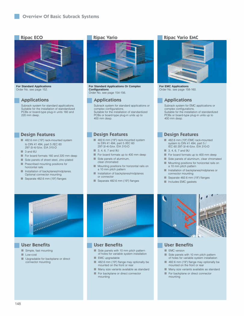
148
Overview Of Basic Subrack Systems
Ripac ECO
For Standard ApplicationsOrder No. see page 152.
ApplicationsSubrack system for standard applications. Suitable for the installation of standardizedPCBs or board-type plug-in units 160 and 220 mm deep.
User Benefits Simple, fast mounting Low-cost Upgradable for backplane or direct
connector mounting
Ripac Vario EMC
For EMC ApplicationsOrder No. see page 158-160.
User Benefits EMC version Side panels with 10 mm pitch pattern
of holes for variable system installation 482.6 mm (19") flange may optionally be
mounted on the front or rear Many size variants available as standard For backplane or direct connector
mounting
Ripac Vario
For Standard Applications Or Complex ConfigurationsOrder No. see page 154-156.
User Benefits Side panels with 10 mm pitch pattern
of holes for variable system installation EMC upgradable 482.6 mm (19") flange may optionally be
mounted on the front or rear Many size variants available as standard For backplane or direct connector
mounting
ApplicationsSubrack system for standard applications orcomplex configurations. Suitable for the installation of standardizedPCBs or board-type plug-in units up to 400 mm deep.
ApplicationsSubrack system for EMC applications or complex configurations. Suitable for the installation of standardizedPCBs or board-type plug-in units up to 400 mm deep.
Design Features 482.6 mm (19") rack-mounted system
to DIN 41 494, part 5 /IEC 60 297-3/-4/-5/xx. EIA 310-D
3 and 6U For board formats 160 and 220 mm deep Side panels of sheet steel, zinc-plated Prescribed mounting positions for
horizontal rails Installation of backplanes/midplanes.
Optional connector mounting Separate 482.6 mm (19") flanges
Design Features 482.6 mm (19") rack-mounted system
to DIN 41 494, part 5 /IEC 60 297-3/-4/-5/xx. EIA 310-D
3, 4, 6, 7 and 9U For board formats up to 400 mm deep Side panels of aluminum,
clear chromated Mounting positions for horizontal rails on
a 10 mm pitch pattern Installation of backplanes/midplanes
or connector Separate 482.6 mm (19") flanges
Design Features 482.6 mm (19") EMC rack-mounted
system to DIN 41 494, part 5 /IEC 60 297-3/-4/-5/xx. EIA 310-D
3, 4, 6, 7 and 9U For board formats up to 400 mm deep Side panels of aluminum, clear chromated Mounting positions for horizontal rails on
a 10 mm pitch pattern Installation of backplanes/midplanes or
connector mounting Separate 482.6 mm (19") flanges Includes EMC gaskets
Section 3_104-155 4/7/04 8:51 AM Page 45

149
Overview Of Basic Subrack Systems
Ripac Compact
For Mounting Plates Or Mounting RailsOrder No. see page 162.
ApplicationsSubrack system for direct mounting in the enclosure. May optionally be mounted on a rail or mounting plate. Suitable for the installation of standardizedPCBs or board type plug-in units.
User Benefits Direct mounting on mounting plates
or rails Variable cable entry from below or above Side panels with 10 mm pitch pattern
of holes for variable system installation For backplane mounting
Ripac Vario Mobil
For Mobile ApplicationsOrder No. see page 164.
User Benefits Suitable for use in rail vehicles EMC version optional Side panels with 10 mm pitch pattern
of holes for variable system installation Fully assembled For backplane and direct connector
mounting
ApplicationsSubrack system for use in rail vehicles.Suitable for the installation of standardizedPCBs or board type plug-in units.
Design Features Rack-mounted system to DIN 41 494,
part 5 /IEC 60 297-3 EIA 310-D Prepared for mounting on top hat rails
or directly on the mounting plate 3 and 6U For board formats up to 160 mm deep Installation width: 21 and 42HP Side panels of aluminum, clear chromated Installation of backplanes/midplanes
Design Features 482.6 mm (19") rack-mounted system to
DIN 41 494, part 5 /IEC 60 297-3EIA 310-D
Tested to EN 50 155 (ElectronicEquipment in Rail Vehicles)
3 and 6U For board formats up to 220 mm deep Side panels of aluminum,
clear chromated Installation of backplanes/midplanes or
connector mounting Fully assembled
Section 3_104-155 4/7/04 8:51 AM Page 46

Modular CompactPCI BackplanesModular Subrack Systems
Product Diversity Knowledge Transfer MPS Expertise Globalization Integrative Thinking
150
Design Features Of Vario, Vario EMC And Vario Mobil
Side Panels And Flangesof clear chromated aluminum.Optional front horizontal rails with 10 mm extension.
10 mm Pitch Patternin the side panels permits depth-variable system configuration.
Complex Application Options A wide choice of size variants isavailable as standard. Also upgrad-able for complex applications.
EMC Shieldingdue to horizontal and vertical EMCgaskets. Also suitable for retro-fitting.
Design Features Of Ripac Compact
Side Panels And Flangesof clear chromated aluminum. 10 mm pitch pattern for variable system installation.
Rail Mounting Rear adapter permits easy snap-fitting directly onto the rail.
Mounting On Mounting PanelsMachined keyholes for direct mounting on mounting panels.
Design Features Of Ripac ECO
Side Panelsof clear chromated aluminum extrusionPrescribed mounting positions for 160and 220 mm board formats.
Cover Mounting The cover simply slides into the horizontal rails.
System Configuration, Accessories
Guide Railsmade of plastic, aluminum or keyable.Order No. see page 182
Coversslotted or solid, snap-type or screw-fastening.Order No. see page 188
ESD EquipmentESD clips for guide rails to discharge static charges.Order No. see page 185
EMC Versionoptional.
KeysFor keying the board type plug-in units.Order No. see page 186
Section 3_104-155 4/7/04 8:51 AM Page 47

At A Glance: Basic Subrack SystemsThe modular concept of Kaparel/Rittal subracks permits a wide range of applications with the minimum number of components, since all Ripac subracks are based on the same horizontal rails and system components.The only difference lies in the design of the side panels and configurationvariants. Equipped with a backplane and power supply, a standard subrackcan be rapidly upgraded to an MPS system, for example. The subracks areshock and vibration-tested and conform to IEC 60 297-3, 60 297-4, 60 297-5-103 and IEEE 1101.1/1101.10.
Subrack system for individual configuration
5 basic versions for different applications
Horizontal rails and accessories to match all variants
EMC upgradable
Fully assembled and wired upon request
VMEbus
151
System Configuration, Accessories
Front Panelsin various designs e.g. with handles, vented or for EMC applications.Order No. see page 199
Front Panel Handlesself locking, made from plastic or aluminum.Order No. see page 199
Assembly Kitsfor combined installation ofEuroboards and double-Euroboards,horizontal or vertical.Order No. see page 180
Section 3_104-155 4/7/04 8:51 AM Page 48

152
Order Information
ECO Subracks 3U And 6U
Order Ño. Order No. Order No. Order No. Pagesubrack side panels subrack side panels
ripac ECO ripac ECO U 3 3 6 6Side panel depth (T) mm A Max.board depth
mm mm180 155 160 3684001 3684502 3684007 3684505240 215 220 3684002 3684503 3684008 3684506
Subrack Aupply Includes (Unassembled) For Backplane MountingU 3 6
Order No. QuantitySide panels see above 2 2 168
A Front horizontal rails 3684562 2 2 173C4 Rear horizontal rails 3688104 2 2 175D1 Rear horiz. rails, centre 3684582 – 1 1761 Threaded inserts 3684610 4 4 177
Assembly screws M4 x 12 3684881 8 10 219Accessories For Additional Configuration (Order Separately)
U 3 6Order No. Quantity required
F Z rail 3684602 2 4 177C5 Rear horiz. rails with integr. Z rail 9901991 2 2 177G Insulating strips 3684611 8 16 178
Cover vented for 175 mm side panel 3688105 2 2 191Cover vented for 210 mm side panel 3688106 2 2 191Cover solid for 175 mm side panel 3688107 2 2 191Cover solid for 210 mm side panel 3688108 2 2 191Mounting block for cover plate 3688109 Variable Variable 191Assembly screws for cover 9902188 Variable Variable 218
Please order insulating stripsand Z rails separately.
3U
6U
HE = UTE = HP
Section 3_104-155 4/7/04 8:51 AM Page 49

153
Order Information ECO Subracks 3U And 6U
Technical Specifications:Overall depth: 175, 235 mmInstallation width: 84HPHeight: 3U, 6UDesigned for backplane mounting, oroptionally, for connector mounting.Suitable for PCB depth 160 and 220 mm
Material/Surface Finish:Side panels: 1.5 mm extruded aluminum, clear chromatedFlanges/horizontal rails: extruded aluminum section, clear chromatedTests:
Vibration and shock-tested to:DIN IEC 68-2-6 test FcDIN IEC 68-2-27 test Ea
Standards:The Ripac subracks are based on system dimensions to DIN 41 494, part 5 and IEC 60 297-3 EIA 310-D.
Accessories:
Handles /front panels/box type plug-in units, from page 199Configuration/climate control, from page 220
A
A
C4
C4
A
A
C4
C4
D1
Horizontal Rail Configurations:
Ripac ECO 3U for backplane.
Ripac ECO 6U for backplane.
Simple assembly of the covers.
Section 3_104-155 4/7/04 8:51 AM Page 50

154
Order Information
Vario Subracks 3U/6U/9U
Order No. Order No. Order No. Order No. Order No. Order No. PageSubrack Ripac Side Subrack Ripac Side Subrack Ripac Side
Vario panels Vario panels Vario panelsU 3 3 3 6 6 6 9 9 9
Side a Max. For For For For For For For For Forpanels mm PCB depth backplane connector subrack backplane connector subrack backplane connector subrack(T) mm mm DIN Ripac DIN Ripac DIN Ripac
41 612 Vario 41 612 Vario 41 612 Vario185 160 160 3684020 3684034 3684511 3684043 3684056 3684529 – – –225 200 160 3684021 3684035 3684512 3684044 3684057 3684530 – – –245 220 220 3684022 3684036 3684513 3684045 3684058 3684531 – – –285 260 220 3684023 3685281 3684514 3684046 – 3684532 – – –305 280 280 3685231 3685233 3684515 3685238 3685240 3684533 – – –345 320 280 3684024 – 3684516 3684047 – 3684534 3684051 3684059 3684547365 340 340 3685232 3685234 3684517 3685239 – 3684535 – – –405 380 340 3684025 – 3684518 3684048 – 3684536 3684052 3684060 3684548465 440 400 3684026 – 3684520 3684049 – 3684538 3684053 3684061 3684549525 500 400 3684027 – 3684521 3684050 – 3684539 3684054 – 3684550585 560 400 – – 3684522 – – 3684540 3684055 – 3684551
Subrack Supply Includes (Unassembled)U 3 3 3 6 6 6 9 9 9
Rail For For Order No. For For Order No. For For Order No.type backplane connector Flanges backplane connector Flanges backplane connector Flanges
Order No. QuantityFlanges 19 inch – 2 2 3684615 2 2 3684617 2 2 3684619 169Side panels See above 2 2 2 2 2 2 168
A Horiz. rails, front 3684562 2 2 2 2 2 2 173I Threaded inserts 3684610 2 2 2 2 2 2 177
C1 Horiz. rails, rear 3684572 2 – 2 – 2 – 175D1 Horiz. rails, rear, center 3684582 – – 1 – 2 – 176G Insulation strips, 21HP 3684611 8 – 16 – 24 – 176C3 Horiz. rails, rear, with 3686159 – 2 – 2 – 2 176
integral Z railsD2 Horiz. rails, rear, center 3687602 – – – 1 – 2
with integral Z railsAssembly screws 3684881 8 8 10 10 12 12 219M4 x 12
84 TE
482.6 (19 )
482.6 (19 )
84 TE
6 H
E3
HE
84 TE
482.6 (19 )
9 H
E
129.
426
2.75
396.
1
T
12.5 a
4.1
4.1
a
T
12.5
12.5
T
a
4.1
124
124
124
124
124
124
19" Flange Section
Section 3_104-155 4/7/04 8:51 AM Page 51

155
Order Information Vario Subrack 3U/6U/9U
Technical Specifications:Overall depth: 185, 225, 245, 285, 305,345, 365, 405, 465, 525, 585 mmInstallation width: 84HPHeight: 3U, 6U, 9UMay be upgraded to EMC version with additional EMC gaskets.
Material:Side panels: 2.5 mm aluminum sheet482.6 mm (19") flanges and horizontalrails: Extruded aluminum
Surface Finish:Clear chromated
Tests:Vibration and shock-tested to:DIN IEC 68-2-6 test FcDIN IEC 68-2-27 test Ea
Standards:The Ripac subrack is based on systemdimensions to DIN 41 494, part 5 andIEC 60 297-3 IEC 60 297-AIEC 60 297-5-103EIA 310-D
Accessories:EMC accessories, from page 177Handles/front panels/box type plug-in units, from page 199For cooling, see page 220
A
A
A
A
C1+G
C1+G
C3
C3
A
A
C1+G
C1+G
D1+G
A
A
C3
C3
D2
A C1+G
D1+G
D1+G
A C1+G
Horizontal Rail Configurations:
Ripac Vario 3UTop: For backplane mtgBottom: For direct connector mtg.
Ripac Vario 6UTop: For backplaneBottom: For direct connector mtg.
Ripac Vario 9Ufor backplane mtg.
A
A
C3
D2
D2
C3
Ripac Vario 9Ufor direct connector mtg.
Section 3_104-155 4/7/04 8:51 AM Page 52

156
Order Information
Vario System Subracks 4U And 7U
Order No. Order No. Order No. Order No. Order No. Order No. Order No. Order No. PageSubrack Side Subrack Side Subrack Side Subrack Side
Vario panels Vario panels Vario panels Vario panelsU 4 4 4 4 4 4 7 7 7 7
(3 + 1) (3 + 1) (3 + 1) (3 + 2x1/2) (3 + 2x1/2) (3 + 2x1/2) (6 + 1) (6 + 1) (6 + 2x1/2) (6 + 2x1/2)Side a Max. For For For For For For For For For Forpanel mm PCB backplane connector subrack backplane connector subrack backplane subrack backplane subrack
depth (T) depth DIN Ripac DIN Ripac Ripac Ripacmm mm 41 612 Vario 41 612 Vario Vario Vario245 220 220 3685235 – 3685850 – – 3685891 – 3685897 – 3685894285 260 220 3684028 3684037 3684523 3684031 3684040 3684526 – 3685743 – 3685895305 280 280 3685236 – 3685794 – – – – – – –345 320 280 3684029 3684038 3684524 3684032 3684041 3684527 – 3685744 – 3685745365 340 340 3685237 – 3685795 – – – – – – –405 380 340 3684030 3684039 3684525 3684033 3684042 3684528 3684064 3684541 3684062 3684543465 440 400 – – 3685796 – – 3685892 3684065 3684542 3684063 3684544
Subrack Supply Includes (Unassembled)Rail U 4 4 4 4 4 4 7 7 7 7type (3 + 1) (3 + 1) (3 + 1) (3 + 2x1/2) (3 + 2x1/2) (3 + 2x1/2) (6 + 1) (6 + 1) (6 + 2x1/2) (6 + 2x1/2)
For For Order No. For For Order No. For Order No. For Order No.backplane connector Flange backplane connector Flange backplane Flange backplane Flange
Order No. QuantityFlange 19" – 2 2 3684616 2 2 3684616 2 3684618 2 3684618 169Side panels see above 2 2 2 2 2 2 168
A Horiz. rails, front 3684562 2 2 2 2 2 2 173I Threaded inserts 3684610 2 2 2 2 2 2 177
C1 Horiz. rails, rear 3684572 2 – 2 – 2 2 175D1 Horiz. rails, rear, 3684582 – – – – 1 1 176
centerG Insulating strips 3684611 8 – 8 – 16 16 178
21 HPC3 Horiz. rails, rear 3686159 – 2 – 2 – – 176
with integral Z railsD2 Horiz. rails, rear, 3687602 – – – – – –
center, with integral Z railsAssembly screws 3684881 8 8 8 8 10 10 219M4 x 12
a
4.1
T
T
4.1
a
262.
7526
2.75
a
4.1
T
T
4.1
a
124
124
129.
412
9.4
124
124
124
124
35.1
84 TE482.6 (19″)
482.6 (19″)
84 TE
84 TE
482.6 (19″)
482.6 (19″)
84 TE
3 H
E1
HE
3 H
E1 /
2 H
E
1 /2
HE
1 /2
HE
1 /2
HE
1 H
E6
HE
6 H
E
12.5
12.5
12.5
12.5
35.1
19" Flange Section
Section 4_156-199 4/7/04 8:53 AM Page 1

157
Order Information Vario System Subracks 4U And 7U
Technical Specifications:Overall depth: 245, 285, 305, 345, 365,405, 465 mmInstallation width: 84HPHeight: 4U, 7U
May be upgraded to EMC version withadditional gaskets.
Material:Side panels: 2.5 mm aluminum sheet 482.6 mm (19") flangesand horizontal rails:Extruded aluminum
Surface Finish:Clear chromated
Tests:Vibration and shock-tested to:DIN IEC 68-2-6 test FcDIN IEC 68-2-27 test Ea
Standards:The Ripac subrack is based on systemdimensions to DIN 41494 494, part 5and IEC 60 297-3, IEC 60 297-4, IEC60 297-5-103, EIA 310-D.
Accessories:EMC accessories, from page 177
Handles/front panels/box type plug-in units, from page 199
For cooling, see page 220
A
A
C1+G
C1+G
A
A
C3
C3
A
A
C1+G
C1+G
A
A
C3
C3
A
A
C1+G
C1+G
D1+G
A
A
C1+G
C1+G
D1+G
Horizontal Rail Configurations:
Ripac Vario 4U (3U + 1U)Top: For backplane mountingBottom: For direct connector mounting.
Ripac Vario 4U (3U + 2 x 1/2U)Top: For backplane mountingBottom: For direct connector mounting.
Ripac Vario 4U (6U + 2 x 1/2U)for backplane mounting.
Ripac Vario 7U (6U + 1U)for backplane mounting.
Section 4_156-199 4/7/04 8:53 AM Page 2

158
Order Information
Vario EMC System Suback 3U/6U/9U
Order No. Subrack Order No. Order No. Subrack Order No. Order No. Subrack Order No. PageVario EMC Side panels Vario EMC Side panels Vario EMC Side panels
U 3 3 3 6 6 6 9 9 9Side panel a Max. card For backplane For subrack For backplane For subrack For backplane For subrack
depth mm depth mm Ripac Ripac Ripac(T) mm Vario EMC Vario EMC Vario EMC
245 220 160 3684128 3684142* 3684513 3684156 3684169* 3684531 – – –285 260 220 3684129 3684143* 3684514 3684157 3684170* 3684532 – – –305 280 220 3685241 3685243* 3684515 3685242 3685244* 3684533 – – –345 320 280 3684130 3684144* 3684516 3684158 3684171* 3684534 3684162 3684175* 3684547405 380 340 3684131 3684145* 3684518 3684159 3684172* 3684536 3684163 3684176* 3684548465 440 400 3684132 3684146* 3684520 3684160 3684173* 3684538 3684164 3684177* 3684549525 500 400 3684133 3684147* 3684521 3684161 3684174* 3684539 3684165 3684178* 3684550585 560 400 – – 3684522 – – 3684540 3684166 3684179* 3684551
*Front horizontal rails with 10 mm extension for type IV or VII injector/extractor handles
Subrack Supply Includes (Unassembled)U 3 3 3 6 6 6 9 9 9
Rail For backplane Order No. For backplane Order No. For backplane Order No.type Flange/ Flange/ Flange/
EMC gasket EMC gasket EMC gasketOrder No. Quantity
Flanges – 2 2* 3684615 2 2* 3684617 2 2* 3684619 169Trim sections – 2 2* 3684634 2 2* 3684636 2 2* 3684638Side panels See above 2 2* 2 2* 2 2* 168EMC gaskets, vertical – 4 4* 3686975 4 4* 3686977 4 4* 3686979 179Covers, slotted – 2 2* 2 2* 2 2* 188Mounting blocks 3684884 Depending on depth 190
K EMC gaskets for 3684807 4 4* 4 4* 4 4* 177covers
A Front horiz. rails 3684562 4 3* 4 2* 4 2* 173I Threaded inserts 3684610 4 4* 4 4* 4 4* 177B Front horiz. rails
with 10 mm exten. 3684567 – 1* – 2* – 2* 173C1 Rear horiz. rails 3684572 2 2* 2 2* 2 2* 175D1 Rear horiz.
rails, center 3684582 – – 1 1* 2 2* 176G Insulating strips
21HP 3684611 8 8* 16 16* 24 24* 176Assembly screws 3684881 12 12* 14 14* 16 16* 219M4 x 12
9U
HE = UTE = HP
19" Flange SectionTear Trim Section
4.1
4.1
T
124
124
12.5
a12.5
a
124
T
129.
426
2.75
6 H
E
482.6 (19 )
84 TE
84 TE
482.6 (19 )
3 H
E
12.5
T
a
4.1
124
124
124
396.
1
9 H
E
84 TE
482.6 (19 )
6U
3U
19" Flange/sectionTear Trim Section
Section 4_156-199 4/7/04 8:53 AM Page 3

159
Order Information Vario EMC System Subrack 3U/6U/9U
Technical Specifications:Overall depth: 245, 285, 305, 345, 405,465, 525, 585 mmInstallation width: 84HPHeight: 3U, 6U, 9U
Material:Side panels:2.5 mm aluminum sheetFlanges and horizontal rails:Extruded aluminumCovers: Aluminum
Surface Finish:Clear chromated
Tests:Vibration and shock-tested to:DIN IEC 68-2-6 test FcDIN IEC 68-2-27 test Ea
Standards:The Ripac subrack is based on systemdimensions to DIN 41 494, part 5 and IEC 60 297-3, -4, -5-103, EIA 310-D.
Accessories:Handles/front panels/box type plug-in units, from page 199
For cooling, see page 220
C1+G
C1+G
A
A
B
B
A
A
C1+G
C1+G
A
A
A
A
A
A
C1+G
D1+G
D1+G
C1+G C1+G
C1+G
D1+G
D1+G
A
A
B
B
Horizontal Rail Configurations:
Ripac Vario EMC 3UTop: For backplane mountingBottom: For backplane/front horizontal rails with 10 mm extension.
Ripac Vario EMV 6UTop: For backplane mountingBottom: For backplane/front horizontal rails with 10 mm extension.
Ripac Vario EMV 9Ufor backplane mounting.
Ripac Vario EMV 9Ufor backplane mounting/front horizontal rails with 10 mm extension.
A
A
C1+G
C1+G
D1+G
A
A
A
A
B
B
C1+G
C1+G
D1+G
Section 4_156-199 4/7/04 8:53 AM Page 4

a
4.1
T
T
4.1
a
124
124
129.
412
9.4
35.1
12.5
12.5 84 TE
482.6 (19″)
482.6 (19″)
84 TE
3 H
E1
HE
3 H
E1 /
2 H
E1 /
2 H
E
a
4.1
T
T
4.1
a
262.
7526
2.75
124
124
124
124
12.5
12.5
35.1
84 TE482.6 (19″)
482.6 (19″)
84 TE
1 /2
HE
1 /2
HE
1 H
E6
HE
6 H
E
160
Order Information
Vario EMC System Subracks 4U And 7U
Order No. Subrack Order No. Subrack Order No. Subrack Order No. Subrack PageVario EMC Vario EMC Vario EMC Vario EMC
U 4 4 4 4 7 7 7 7(3 + 1) (3 + 1) (3 + 2x1/2) (3 + 2x1/2) (6 + 1) (6 + 1) (6 + 2x1/2) (6 + 2x1/2)
Side panel a Max. card For For For For For For For Fordepth (T) mm mm depth mm backplane backplane* backplane backplane* backplane backplane* backplane backplane*
285 260 220 3684134 3684148 3684137 3684151 3684187 3684192 – –345 320 280 3684135 3684149 3684138 3684152 3684188 3684193 3684189 3684196405 380 340 3684136 3684150 3684139 3684153 3684180 3684194 3684190 3684197465 440 400 – – – – 3684181 3684195 3684191 3684198
*Front horizontal rails with 10 mm extension for type IV or VII injector/extractor handles
Subrack Supply Includes (Unassembled)Rail U 4 4 4 4 7 7 7 7type (3 + 1) (3 + 1) (3 + 2x1/2) (3 + 2x1/2) (6 + 1) (6 + 1) (6 + 2x1/2) (6 + 2x1/2)
For For For For For For For Forbackplane backplane* backplane backplane* backplane backplane* backplane backplane*
Best.-Nr.2 flanges 3684616 3684618 1692 trim sections, rear 3684635 3684637 1712 side panels 285 mm deep 3684523 3684526 3685743 3685895 1682 side panels 345 mm deep 3684524 3684527 3685744 3685745 1682 side panels 405 mm deep 3684525 3684528 3684541 3684543 1682 side panels 465 mm deep 3685796 3685892 3684542 3684544 168
EMC gaskets, vertical 4 4 3 3 4 4 3 3 179Cover, flat, slotted 2 2 – – 2 2 – – 188Cover, L-shaped, – – 2 2 – – 2 21/2U, top unslotted, bottom slotted at front (1set)Mounting blocks 3684884 Depending on depth 190
K EMC gaskets for covers 3684807 4 4 2 2 4 4 2 2 177A Front horizontal rails 3684562 6 5 4 3 6 4 4 2 173I Threaded inserts 3684610 6 6 4 4 6 6 4 4 177B Front horizontal rails with 3684567 – 1 – 1 – 2 – 2 173
10 mm extensionC1 Rear horizontal rails 3684572 2 2 2 2 2 2 2 2 175D1 Rear horizontal rails, center 3684582 – – – – 1 1 1 1 176G Insulating strips 21HP 3684611 8 8 8 8 16 16 16 16 178
Assembly screws M 4 x 12 3684881 16 16 12 12 18 18 14 14 219
19" Flange/Section/Rear Trim Section
4U(3U + 1U)
4U(3U + 2 x .5U)
7U(6U + 2 x .5U)
7U(6U + 1U)
HE = UTE = HP
Section 4_156-199 4/7/04 8:53 AM Page 5

161
Order Information Vario EMC System Subrack 4U And 7U
Technical Specifications:Overall depth: 285, 345, 405, 465 mmInstallation width: 84HPHeight: 4U, 7U
Material:Side panels:2.5 mm aluminum sheetFlanges and horizontal rails:Extruded aluminumCovers: Aluminum
Surface Finish:Clear chromated
Tests:Vibration and shock-tested to:DIN IEC 68-2-6 test FcDIN IEC 68-2-27 test Ea
Standards:The Ripac subrack is based on systemdimensions to DIN 41 494, part 5, IEC 60 297-3, IEC 60 297-4, IEC 60 297-5-103, EIA 310-D, IEEE 1101.1 and 1101.10
Horizontal Rail Configurations:
4U (3U + 1U)Top: For backplaneBottom: For backplane mounting/front horizontal rails with 10 mm extension.
4U (3U + 2x1/2U)Top: For backplaneBottom: For backplane mounting/front horizontal rails with 10 mm extension.
7U (6U + 1U)Top: For backplaneBottom: For backplane mounting/front horizontal rails with 10 mm extension.
7U (6U + 2x1/2U)Top: For backplaneBottom: For backplane mounting/front horizontal rails with 10 mm extension.
dB
MHz
1
100
0.01 0.05 0.1 0.5 5 10 50 100 500 1000 5000
80
60
40
20
0
120
Accessories:Handles/front panels/box type plug-inunits, from page 199For cooling, see page 220
Section 4_156-199 4/7/04 8:53 AM Page 6

162
Order Information
Compact System Subracks 3U And 6U
Order No. Subrack Order No. EMC Subrack PageU 3 3 3 3 6 3 3 3 3 6HP 21 21 42 42 42 21 21 42 42 42Mounting Mounting Mounting Mounting Mounting Mounting Mounting Mounting Mounting Mounting Mounting
rail plate rail plate plate rail plate rail plate plateSide panel a Max. PCB For For For For For For For For For Fordepth (T) mm depth backplane backplane backplane backplane backplane backplane backplane backplane backplane backplane
mm mm mounting mounting mounting mounting mounting mounting mounting mounting mounting mounting225 200 160 3687667 3687669 3687671 3687673 3687680 3687682 3687684 3687686 3687688 3687690285 260 220 3687668 3687670 3687672 3687674 3687681 3687683 3687685 3687687 3687689 3687691
Subrack Supply Includes (Unassembled) For Backplane MountingRail type
Side panels 2 2 2 2 2 1 1 1 1 1 168Side panels for cable entry – – – – – 1 1 1 1 1EMC tight cable entry – – – – – 1 1 1 1 1Trim sections 4 2 4 2 2 4 2 4 2 2 171Flange with keyhole – 2 – 2 2 – 2 – 2 2EMC front/rear panels – – – – – – 1 – 1 1 169EMC rear panels for mounting – – – – – 1 – 1 – –rail adapterRear panel for mounting 1 – 1 – – – – – – –rail adapterMounting rail adapter 1 – 1 – – 1 – 1 – –EMC gaskets, vertical – – – – – X X X X X 179Covers, vented – – – – – 2 2 2 2 2 188
A Front horizontal rails 4 2 4 2 2 4 4 4 4 4 173C1 Rear horizontal rails 2 2 2 2 2 2 2 2 2 2 175I Threaded inserts 4 2 4 2 2 4 4 4 4 4 177G Insulating strips 21 HP 2 2 4 4 8 2 2 4 4 8 178D1 Rear horizontal rails, center – – – – 1 – – – – 1 176
AccessoriesGuide rails See page 182 – 187Vented covers for 160 PCB 3687624 3687624 3687625 3687625 3687625 Included in supply 191Vented covers for 220 PCB 3687692 3687692 3687677 3687677 3687677 Included in supply 191
F Z rails, DIN 41 612 3684599 3684599 3684600 3684600 3684600 3684599 3684599 3684600 3684600 3684600 177
a
2.75 2.75T
T 2.752.75
a
132
(3 H
E)
251.64/144.96
37.4
357
.15
213.64/106.96
269.64/162.96
132
(3 H
E)
7.5 213.64/106.96
2.75 2.75T
a
265.
35 (6
HE
)
251.64/144.96
190.
5
57.1
537
.43
57.1
5
213.64/106.96
269.64/162.96
3U 6U HE = U
EMC TightCable Entry Device
Section 4_156-199 4/7/04 8:53 AM Page 7

163
Order Information Compact System Subrack 3U And 6U
Cable Inlet:EMC version: Side cable entry throughEMC PG screwed cable entry in theside panel.Non-EMC version: Cable entry fromabove/below
Standards:Ripac subracks are based onthe system dimensions toDIN 41 494, part 5 andIEC 60 297-3, IEEE 1101.1/101.1 and1101.10.
Technical Specifications:Overall depth: 225, 285 mmFor PCB depth: 160 mm and 220 mmInstallation width: 21 and 42HPHeight: 3U, 6UPrepared for mounting on DIN rail ormounting plate
Material:Side panels: 2.5 mm aluminum Flanges and horizontal rails:Extruded aluminum
Surface Finish:Clear chromated
Tests:Vibration and shock-tested to:DIN IEC 68-2-6 test FcDIN IEC 68-2-27 test Ea
Accessories:Handles/front panels/box type plug-in units, from page 199For cooling, see page 220
A
A
C1+G
C1+G
A
A
A
A
C1+G
C1+G
Configurations:
3UTop: For mounting rail Bottom: For mounting plate.
6UTop: For mounting rail Bottom: For mounting plate.
Rail InstallationSimply snap onto the rail by using special adapters.
Mounting Plate InstallationUsing flanges with machined keyholes.
A
A
C1+G
C1+G
D1+G
A
A
A
A
C1+G
C1+G
D1+G
Section 4_156-199 4/7/04 8:53 AM Page 8

164
Order Information
Vario Mobil System 3U And 6U – For Mobile Use
Order No. Subrack Order No. Order No. Order No. Subrack Order No. Order No. PageRipac Vario Mobil Side panels Subrack Ripac Vario Mobil Side panels Subrack
Ripac Vario Ripac VarioMobil EMC Mobil EMC
U 3 3 3 3 6 6 6 6Side panel a Max. card For For For subrack For For For For subrack Fordepth (T) mm depth mm backplane connector Ripac Vario backplane backplane connector Ripac Vario backplane
mm mounting DIN 41 612 mounting mounting DIN 41 612 mounting245 220 220 3687782 3687780 3684513 3687784 3687783 3687781 3684531 3687785
Subrack Supply Included (Assembled)U 3 3 3 3 6 6 6 6
Rail For For For For For Fortype backplane connector backplane backplane connector backplane
Order No. QuantityFlanges 19" – 2 2 3684615 2 2 2 3684617 2 169Trim section – – – 3684634 2 – – 3684636 2 171Side panels See above 2 2 – 2 2 2 – 2 168EMC gaskets, vertical – – – 3686975 2 – – 3686977 2 179Covers, vented 3684695 – – – 2 – – – 2 188Mounting blocks 3684884 – – – 20 – – – 20 190
K EMC gaskets for 3684807 – – – 4 – – – 4 177cover plate
A Front horizontal rails 3684562 4 4 – 4 4 4 – 4 173I Threaded inserts 3684610 4 4 – 4 4 4 – 4 177
C1 Rear horizontal rails 3684572 2 – – 2 2 – – 2 175D1 Rear horizontal 3684582 – – – – 1 – – 1 176
rails, centerG Insulating strips 21 HP 3684611 8 – – 8 16 – – 16 178C3 Rear horizontal rails with 3686159 – 2 – – – 2 – – 176
integral Z railsD2 Rear horizontal rails, 3687602 – – – – – 1 – –
center with integral Z railsAssembly screws 3684881 12 12 – 12 14 14 – 14 219M4 x 12Assembly screws 3684883 – – – 60 – – – 60 219M3 x 6
124
12.5 a
T
4.1
129.
4
3U (EMC version)
6U (EMC version)
Flange/Trim Section
3 H
E
84 TE
482.6 (19")
12.5
124
124
T
a
4.1
262.
75
6 H
E
482.6 (19")
84 TE
Section 4_156-199 4/7/04 8:53 AM Page 9

165
Order Information Vario Mobil System 3U And 6U – For Mobile Use
Technical Specifications:Overall depth: 245 mmInstallation width: 84HPHeight: 3U, 6U
Material:Side panels: 2.5 mm aluminum sheet 482.6 mm (19") flanges and horizontal rails: Extruded aluminumCovers: Aluminum
Surface Finish:Clear chromated
Standards:The Ripac subrack is based on the system dimensions to DIN 41 494, part 5, IEC 60 297-3, IEC 60 297-4, IEC60 297-5-103 and EIA 310-D.
Tests:Vibration and shock-tested to:DIN IEC 68-2-6 test FcDIN IEC 68-2-27 test EaThe subracks have been tested for use in the German national railway. The test was conducted in accordancewith standard EN 50 155 (electronicequipment for rail vehicles). The configuration of the tested subracksconforms to IEC 61587-1.
A
A
A
A
C1+G
C3
C1+G A
A
A
C3 A
A
A C1+G
D1+G
A
A
C3
C3
D2
C1+G A
A
A
A
A
A
A
A
C1+G
C3
C1+G A
A
A
C3 A
A
A C1+G
D1+G
A
A
C3
C3
D2
C1+G A
A
A
A
Horizontal Rail Configurations:
Ripac Vario Mobil EMC 3UTop: For backplane mountingBottom: For connector mounting.
Ripac Vario Mobil EMC 6UTop: For backplane mountingBottom: For connector mounting.
Ripac Vario Mobil 3UTop: For backplane mountingBottom: For connector mounting.
Ripac Vario Mobil 6UTop: For backplane mountingBottom: For connector mounting.
Accessories:Handles /front panels/box type plug-in units, from page 199For cooling, see page 220
Section 4_156-199 4/7/04 8:53 AM Page 10

166
Ripac Subrack Components And Accessories
Section 4_156-199 4/7/04 8:53 AM Page 11

167
Version 5
CoversVersion 1
Version 3 Version 4
Version 2
ComponentsSide panels . . . . . . . . . . . . . . . . . . . . . . . . . . . . . . . . . . .168Flanges . . . . . . . . . . . . . . . . . . . . . . . . . . . . . . . . . . . . . .169
AccessoriesHorizontal rails . . . . . . . . . . . . . . . . . . . . . . . . . . . . . . . . .172EMC gaskets . . . . . . . . . . . . . . . . . . . . . . . . . . . . . . . . . .177
Vertical Divider KitsFor combined installation of Euroboardsand double-Euroboards in 6U subracks . . . . . . . . . . . . . . . . . . . . . . . . . . . . . . . . .180in 6U subracksincluding guide rails . . . . . . . . . . . . . . . . . . . . . . . . . . . . .180in 9U subracks recessed . . . . . . . . . . . . . . . . . . . . . . . . . . . . . . . . . . . . .180for 6U PCBs . . . . . . . . . . . . . . . . . . . . . . . . . . . . . . . . . . .180in 9U subracksFront panel as cover . . . . . . . . . . . . . . . . . . . . . . . . . . . . .180Vertical support . . . . . . . . . . . . . . . . . . . . . . . . . . . . . . . .181
Horizontal Mounting KitsFor horizontal installation of6U/9U PCBsin 3U/4U subracks . . . . . . . . . . . . . . . . . . . . . . . . . . . . . .181Trim frame . . . . . . . . . . . . . . . . . . . . . . . . . . . . . . . . . . . .181Trim frame, vented . . . . . . . . . . . . . . . . . . . . . . . . . . . . . .181Divider panels
Guide RailsFor 80, 160, 220 and 280 mmPCBsPlastic . . . . . . . . . . . . . . . . . . . . . . . . . . . . . . . . . . . . . . . .182Plastic for ESD clips . . . . . . . . . . . . . . . . . . . . . . . . . . . . .182Aluminum . . . . . . . . . . . . . . . . . . . . . . . . . . . . . . . . . . . . .182Plastic, keyable . . . . . . . . . . . . . . . . . . . . . . . . . . . . . . . . .183for rear connection . . . . . . . . . . . . . . . . . . . . . . . . . . . . . .183Aluminum, keyable . . . . . . . . . . . . . . . . . . . . . . . . . . . . . .184with offset (telecom) . . . . . . . . . . . . . . . . . . . . . . . . . . . . .184ESD clipfor keyable plastic guide rails . . . . . . . . . . . . . . . . . . . . . .185Keys . . . . . . . . . . . . . . . . . . . . . . . . . . . . . . . . . . . . . . . . .186Board ejector//PCB retainer . . . . . . . . . . . . . . . . . . . . . . .187for box type plug-in units, types I and II . . . . . . . . . . . . . .187
CoversCovers, version 1 . . . . . . . . . . . . . . . . . . . . . . . . . . . . . . .188Covers, version 2 . . . . . . . . . . . . . . . . . . . . . . . . . . . . . . .189Covers, version 3 . . . . . . . . . . . . . . . . . . . . . . . . . . . . . . .189Covers, version 4 . . . . . . . . . . . . . . . . . . . . . . . . . . . . . . .190Mounting blocks . . . . . . . . . . . . . . . . . . . . . . . . . . . . . . . .190Covers, version 5(snap fastening) . . . . . . . . . . . . . . . . . . . . . . . . . . . . . . . .191Covers for Ripac Eco . . . . . . . . . . . . . . . . . . . . . . . . . . . .191*EMC gaskets for covers . . . . . . . . . . . . . . . . . . . . . . . . .191
Ripac Subrack Installation
Over 8,000 Standard Products
Involvement In Standardization Bodies
And Much More
Section 4_156-199 4/7/04 8:53 AM Page 12

168
Individual Subrack Components
Side Panels And Flanges
Side Panels For Vario, Vario EMC, Compact And Vario Mobil SystemAttachment holes and anti-twist half shears on a 10 mm pitch pattern.
Material:2.5 mm aluminumSurface Finish:Clear chromated
Accessories:Mounting flanges,see page 169Rear flange,see page 170
D (T) a Packs Height (U) Order No.mm mm of 3 4 (3 + 1) 4 (3 + 2 x 1/2) 6 7 (6 + 1) 7 (6 + 2 x 1/2) 9 10 11185 160 1 3684511 – – 3684529 – – – – –225 200 1 3684512 3685793 3685890 3684530 3685896 3685893 3685797 – –245 220 1 3684513 3685850 3685891 3684531 3685897 3685894 – – –285 260 1 3684514 3684523 3684526 3684532 3685743 3685895 – – –305 280 1 3684515 3685794 – 3684533 – – 3685798 – –345 320 1 3684516 3684524 3684527 3684534 3685744 3685745 3684547 – -365 340 1 3684517 3685795 – 3684535 – – 3685799 – –405 380 1 3684518 3684525 3684528 3684536 3684541 3684543 3684548 3684545 –425 400 1 3684519 – – 3684537 – – – – –465 440 1 3684520 3685796 3685892 3684538 3684542 3684544 3684549 3684546 3684552525 500 1 3684521 – – 3684539 3685898 3685959 3684550 3685899 3684553585 560 1 3684522 – – 3684540 – – 3684551 – 3684554
fl 4.1
fl 2
a
T
10
12.5
74110
132
18
11
T
a
1012.5
176.
4574110
1144
.45
21.1
18
fl 4.1
fl 2
T
a
176.
45
10
12.5
1874110
1122.2
3
154.
45
fl 4.1
fl 2
T
a
10
12.5
265.
35
1874110
121.
68
133.
35
11
fl 4.1
fl 2
a
T
10
12.5
309.
8
1874110
121.
68
133.
35
21.7
544.4
5
11
fl 4.1
fl 2
a
T
10
12.5
117411
0
121.
6822
.23
133.
35
309.
8
18
132.
23
fl 4.1
fl 2
T
a
10
12.5
1874110
121.
68
133.
35
11
266.
7
398.
7
fl 4.1
fl 2
a
T
10
12.5
65.5
5
88.9
110
121.
68
133.
35
7411
266.
7
400.
05
443.
15
21.1 18
fl 4.1
fl 2
T
a
10
12.5
18
487.
6
110
74
121.
68
133.
35
1121.1
266.
7
400.
05
fl 4.1
fl 2
3U 4U (3U + 1U) 4U (3U + 2 x 1/2U)
6U 7U (6U + 1U) 7U (6U + 2 x 1/2U)
9U 10U 11U
Section 4_156-199 4/7/04 8:53 AM Page 13

169
482.6 mm (19") Front Flange With T ChannelTo fit all Ripac Vario, Ripac Vario EMC, RipacCompact and Ripac Vario Mobil subracks. The T-slot can be used for the attachment of components, for strain relief or for cable routing.EMC gaskets may be fitted for EMC applications.
Material:Extruded aluminum section
Surface Finish:Clear chromated
Supply Includes:1 front flange
Accessories:EMC gaskets, vertical,see pages 171,179
U Packs Order No.of
3 1 36861926 1 36861939 1 3686194
482.6 mm (19") Mounting FlangeFor all Ripac Vario subracks.
Material:Extruded aluminum
Surface Finish:Clear chromated
Supply Includes:1 mounting flange
Accessories:EMC gaskets, vertical,see pages 171,179
U Packs Order No. Order No.of With Without
Handle Holes Handle Holes2 1 – 36846143 1 3684622 36846154 1 3684623 36846166 1 3684624 36846177 1 3684625 36846189 1 – 368461910 1 – 368462011 1 – 3684621
28
2.5
2.5
5
20
8.2
4.3
2.25
10
7.5
28
2.5
2.5
3.8
5
20
482.6 mm (19") Mounting Flange, RecessedTo fit all Ripac Vario, Ripac Vario EMC, RipacCompact and Ripac Vario Mobil subracks. For recessed mounting in the enclosure.
Material:Extruded aluminum
Surface Finish:Clear chromated
Supply Includes:1 mounting flange
U Packs Order No.of
3 1 36846264 1 36846276 1 36846287 1 36846299 1 368463010 1 368463111 1 3684632
Note: Assembly screws, nuts and washers shouldbe ordered separately.
Packs of Order No.4 set 3687015
Accessories:EMC gaskets, vertical,see page 179
22.75
2.5
25
2.5
Individual Subrack Components Side Panels And Flanges
Section 4_156-199 4/7/04 8:53 AM Page 14

170
Individual Subrack Components
Side Panels And Flanges
Side Panels For ECO SystemAttachment holes for 160 / 220 mm PCB installation. Continuous pitch pattern of holes top and bottom for cover attachment.
Material:2.5 mm aluminum
Surface Finish:clear chromate
Supply Includes:1 side panel
Rear FlangeTo fit all subrack versions. Guarantees an 84HP trimon the rear of the subrack. Integral profile toaccommodate EMC gaskets.
Material:Extruded aluminum
Surface Finish:Clear chromated
Supply Includes:1 trim
Accessories:EMC gaskets, vertical, see pages 171,179
U Order No. Packs of 1 Order No. Packs of 22 3684633 –3 3684634 36852764 3684635 –6 3684636 36852777 3684637 –9 3684638 –10 3684639 –11 3684640 –
D (T) Packs of Max. board Height (U) Order No.mm depth mm 3U 6U180 1 160 3684502 3684505240 1 220 3684503 3684506
Handles For SubracksThe handles are mounted on the flanges via handle holes.
Material:Die-cast aluminum
Surface Finish:Painted, silver-gray
Supply Includes:2 handles, assembly parts
U Packs of Order No.4 2 36360103 2 36360107 2 36660106 2 3666010
For all subracks Ripac Vario, Ripac Vario EMC, Ripac Compact and Ripac Vario Mobil
2
2.5
20
5
2.5
ø 4.1
ø 2
117411
0
132 19" flange
12.5
10
18
aT1
27.8 2.6
ø 4.1
ø 2
117411
0
121.
68
133.
35
19" flange
12.1
10
1826
5.35
aT1
3U
Top view of side plate
6U
Section 4_156-199 4/7/04 8:53 AM Page 15
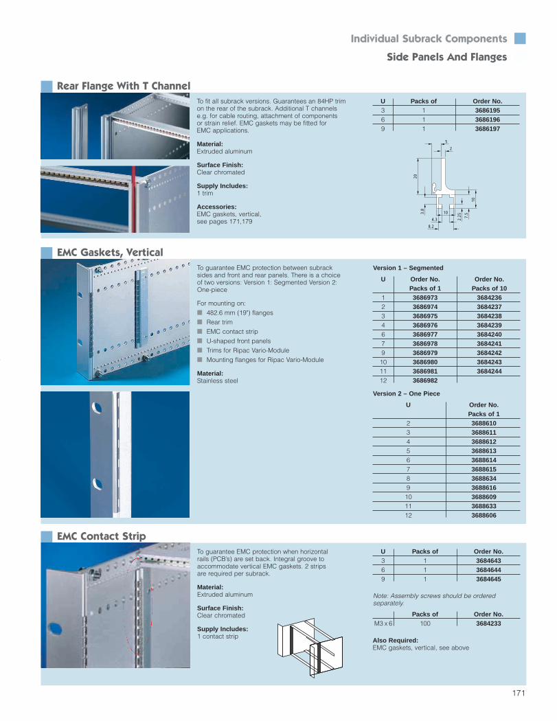
171
Individual Subrack Components Side Panels And Flanges
Rear Flange With T ChannelTo fit all subrack versions. Guarantees an 84HP trimon the rear of the subrack. Additional T channelse.g. for cable routing, attachment of components or strain relief. EMC gaskets may be fitted for EMC applications.
Material:Extruded aluminum
Surface Finish:Clear chromated
Supply Includes:1 trim
Accessories:EMC gaskets, vertical,see pages 171,179
U Packs of Order No.3 1 36861956 1 36861969 1 3686197
10
4.3
2
5
10
7.5
2.25
3.8
20
8.2
EMC Gaskets, VerticalTo guarantee EMC protection between subracksides and front and rear panels. There is a choiceof two versions: Version 1: Segmented Version 2:One-piece
For mounting on: 482.6 mm (19") flanges Rear trim EMC contact strip U-shaped front panels Trims for Ripac Vario-Module Mounting flanges for Ripac Vario-Module
Material:Stainless steel
EMC Contact StripTo guarantee EMC protection when horizontal rails (PCB’s) are set back. Integral groove toaccommodate vertical EMC gaskets. 2 strips are required per subrack.
Material:Extruded aluminum
Surface Finish:Clear chromated
Supply Includes:1 contact strip
U Packs of Order No.3 1 36846436 1 36846449 1 3684645
U Order No. Order No.Packs of 1 Packs of 10
1 3686973 36842362 3686974 36842373 3686975 36842384 3686976 36842396 3686977 36842407 3686978 36842419 3686979 368424210 3686980 368424311 3686981 368424412 3686982
U Order No.Packs of 1
2 36886103 36886114 36886125 36886136 36886147 36886158 36886349 368861610 368860911 368863312 3688606
Version 1 – Segmented
Version 2 – One Piece
Packs of Order No.M3 x 6 100 3684233
Note: Assembly screws should be orderedseparately.
Also Required:EMC gaskets, vertical, see above
Section 4_156-199 4/7/04 8:53 AM Page 16

172
Individual Subrack Components
Horizontal Rails
Ripac Extrusion System: Complete, Simple And Well-OrganizedMain
extrusionsAFront horizontalrail
BFront hori-zontal railwith 10mmextensionfor extractorhandle typeIV or VII
B1Double fronthorizontalrail with 10 mmextension
C1Rear horizontalrail
C3Rear horizontalrail with integral Z rail
C4Rear horizontalrail for Ripac ECO
C5Rear horizontalrail with integral Zrail for Ripac ECO
D1Rear horizontalrail, center
D2Rear horizontalrail, center,with integralZ rail
Additionalextrusions
ERear adapter rail,center, toaccommo-date plasticguide rails
FZ rail forconnectors
GInsulatingstrip*
HConductivestrip*
IThreadedinsert
JIdentificationstrip
KEMC gasket,horizontal
– – – – – – –
– – – –– –
– – – –– –
– – – –– –
– –
– –
––––
All system requirements are coveredby just a few basic horizontal railtypes. This is a well-organized, cost-effective range to fit all subracksystems and the instrument case/rackmounted enclosure range Ripac Vario-Module.
* For conductive or insulated attachment of backplanes
Section 4_156-199 4/7/04 8:53 AM Page 17

173
Individual Subrack Components Horizontal Rails
Front Horizontal Rail (A)For accommodation of guide rails and securing offront panels. HP pitch pattern of holes for exact mounting of
guide rails M 4 thread at ends Straight-through core hole Horizontal rail 192HP for cutting to length
Material:Extruded aluminum
Surface Finish:Clear chromated2)Flash anodized
15.25
1.2
2.3
27
3.4
5.2
6.6
10
24.5
Usable Packs of Order No.width (HP)
4 (left) 1 36845924 (right) 1 36849558 (left) 1 3684593
8 (right) 1 368495612 1 368459416 1 368459520 1 368459621 1 368598540 1 368496042 1 368456063 1 368456184 1 368456284 2 36852671)
192 1 36880002)
1) Including 4 assembly screws
Packs of Order No.M4 x 12 100 3654300
Front Horizontal Rail (B) With 10 mm Extension For Type IV And VII Injector/Extractor HandleFor accommodation of guide rails and securing of front panels. Front projection and hole pattern based on IEEE
1101.10 when using type IV and VII injectors/extractors
HP pitch pattern of holes for exact mounting of guide rails
M 4 thread at ends Straight-through core hole Horizontal rail 192HP for cutting to length
Usable Packs of Order No.width (HP)
40 1 368496142 1 368456563 1 368456684 1 368456784 2 36852691)
192 1 36880012)
1) Including 4 assembly screws
Packs of Order No.M4 x 12 100 3654300
Material:Extruded aluminum
Surface Finish:Clear chromated2)Flash anodized
Note: Order assembly screws separately.
Note: Order assembly screws separately.
EMC gaskets, see page 177
EMC gaskets, see page 177
Section 4_156-199 4/7/04 8:53 AM Page 18

174
Double Front Horizontal Rail, With 10 mm Extension (B1)-Version 2
Under B1 there are 3 Versions available:Version 1 for Dual PCB sizes (2 x 3U or 3U and 6U)
above each other or mixed PCB sizes (2 x 3U next to 6U or 6U + 3U next to 9U)
Version 2 for maximum load carrying in a minimum overall system height or for the horizontalmounting of PCBs in a Pizza Box
Version 3 for max load carrying in combinations with other standard front horizontal rails (see above)
Double horizontal rails are designed for: Improved load carrying (48 kg [8.8 lbs] per
PCB at 4HP Improved connector force encounter (over 1000N
[225 lbf] per slot) Anti twist Injector/Extractor Handle interface 9U applications Max airflow design (max gap between
front/rear rail)
Individual Subrack Components
Double Horizontal Rails
Double Front Horizontal Rail, With 10 mm Extension (B1)-Version 1For the attachment of Guide Rails on both sides.One side with 10 mm extensionOne side without 10 mm extension
Material/Surface Finish:Clear chromated
EMC gaskets, see page 177
For the attachment of Guide Rails on one side only.One side with 10 mm extensionOne side without 10 mm extension
Material/Surface Finish:Clear chromated
EMC gaskets, see page 177
Usable Packs of Order No.width (HP)
84 1 3688704
Note: Order assembly screws separately.
Packs of Order No.M4 x 12 100 3654300
Note: Order assembly screws separately.
Packs of Order No.M4 x 12 100 3654300
19.959.35
6.00
20.00
12.75
10.00
Double Front Horizontal Rail, With 10 mm Extension (B1)-Version 3For the attachment of guide rails on one side only.
Material/Surface:Clear chromated
EMC gaskets, see page 177
34.35
20.00
12.756.00 9.35 19.00
11.00
Usable Packs of Order No.width (HP)
84 1 3688024
Note: Order assembly screws separately.
Packs of Order No.M4 x 12 100 3654300
Usable Packs of Order No.width (HP)
84 1 3687724
23.359.35
6.00
20.00
12.75
10.00
EMC improvement (no gap between 2 rails) Dual or mixed PCB size applications (2 x 3U
in 6U, etc)
Section 4_156-199 4/7/04 8:53 AM Page 19

175
Individual Subrack Components Horizontal Rails
Rear Horizontal Rail (C1)For accommodation of guide rails and securing ofZ rails, insulating or contact strips. HP pitch pattern of holes for precise installation
of guide rails M 2.5 for fastening the Z rails, insulating or
contact strips and backplanes M4 thread at ends Straight-through core hole Horizontal rail 192HP for cutting to length
Material:Extruded aluminum
Surface Finish:Clear chromated2)Flash anodized
5.4
6
9
6
11.75
23.5
8
Usable Packs of Order No.width (HP)
21 1 368599140 1 368496242 1 368457063 1 368457184 1 368457284 2 36852681)
192 1 36880022)
1) Including 4 assembly screws
Packs of Order No.M4 x 12 100 3654300
Rear Horizontal Rail With Channel For Ripac ECO (C4)To accommodate guide rails and for the attachmentof Z rails, insulating strips or contact strips. HP pitch pattern of holes for precise installation
of guide rails Channel to slide in cover plates Threaded inserts (PS3684610) are additionally
required for mounting backplanes/Z rails M4 thread at ends Straight-through core hole Not suitable for mounting under cover plates
Material:Extruded aluminum
Surface Finish:Clear chromated
Note: M4 x 12 assembly screws should be orderedseparately, see above.
Usable Packs of Order No.width (HP)
84 1 3688104
1.45
1.4
11.75
3.4
1.4
2.3
10
23.5
Note: Order assembly screws separately.
Section 4_156-199 4/7/04 8:53 AM Page 20

176
Individual Subrack Components
Horizontal Rails
Rear Horizontal Rail With Integral Z Rail (C3)For accommodation of guide rails. Integral Z rail formounting of DIN 41 612 connectors. HP pitch pattern of holes for exact mounting of
guide rails 84 threaded holes M2.5 for fitting DIN 41 612
connectors M4 thread at ends Straight-through core hole
Material:Extruded aluminum
Surface Finish:Clear chromated
28
20
212.8
10.6
119
2.1
3.5
12.211.8
22.4
6.3
Usable Packs of Order No.width (HP)
42 1 368619163 1 368691984 1 3686159
Note: Order assembly screws separately.
Packs of Order No.M4 x 12 100 3654300
Rear Horizontal Rail, Center (D1)When using 6 U PCBs or modules. Mounting facility for Z rails, insulating or contact strips and backplanes. 84 threaded holes M2.5 M4 thread at ends Straight-through core hole Horizontal rail 192HP for cutting to length
Material:Extruded aluminum
Surface Finish:Clear chromated2)Flash anodized
3.2
7.25
6.75
15.3 8
10.5
21.3
Usable Packs of Order No.width (HP)
40 1 368496342 1 368458063 1 368458184 1 368458284 1 36852701)
192 1 36880032)
1)including 2 assembly screws
Packs of Order No.M4 x 12 100 3654300
Rear Adapter Rail, Center (E)When dividing 6U into 2 x 3U, the adapter rail fastened to the center horizontal rail accommodates the guide rails. HP pitch pattern of holes for precise installation
of guide rails M4 and M2.5 thread at ends Straight-through core hole Horizontal rail 192HP for cutting to length
Material:Extruded aluminum
Surface Finish:Clear chromated2)Flash anodized
2.15
15.2
12.3
6
14.9
3.2
13
16.8
6.15
21.3
Usable Packs of Order No.width (HP)
4 1 36845858 1 368458612 1 368458716 1 368458820 1 368458940 1 368496442 1 368459063 1 368600584 1 368459184 1 36852721)
192 1 36880042)
1)including 2 assembly screws
Packs of Order No.M4 x 12 100 3654300
Note: Order assembly screws separately.
Note: Order assembly screws separately.
Section 4_156-199 4/7/04 8:53 AM Page 21

177
Individual Subrack Components Horizontal Rails
Z Rail For Connectors DIN 41 612 (F)With 84 x M2.5 thread.
Material:Extruded aluminum
Surface Finish:Clear chromated
8.25 21
.5
1
3
Usable Packs of Order No.width (HP)
4 1 36845978 1 368459820 1 368459940 1 368496542 1 368460063 1 368460184 1 368460284 2 3685271
Note: Order assembly screws separately.
Packs of Order No.M2.5 x 6 100 3654340
Threaded Insert (I)With M 2.5 threaded holes in a 1HP pitch pattern.For pushing into front horizontal rails and rear railsof Ripac ECO, type A and type B.
Material:Steel
Surface Finish:Zinc-plated, passivated
Usable Packs of Order No.width (HP)
4 1 36846038 1 368460412 1 368460516 1 368460620 1 368460721 1 368614940 1 368496642 1 368460863 1 368460984 1 3684610
EMC Gaskets, Horizontal (K)As horizontal EMC protection. For snapping ontothe front horizontal rails.
Material:Stainless steel
Usable Packs of Order No.width (HP)
For upper / lower horizontal rail40 1 368497484 1 368480884 10 3684246
When dividing 6U into 2 x 3U, betweentwo horizontal rails
84 1 368578984 10 3685229
Identification Strips (J)For identifying the installation positions on the subrack, self-adhesive. The following versions are available: 4 mm wide: For front rails, horizontal rails 4 mm wide: For rear horizontal rails 2 mm wide: For front horizontal rails (groove)
Width Packs of Labeling Order No.4 mm 2 1 ... 84 3687575*4 mm 2 1 ... 168 36875774 mm 2 84 ... 1 3687574*2 mm 2 1 ... 84 3687576*
* Extended delivery times
Section 4_156-199 4/7/04 8:54 AM Page 22

178
Contact Strip (H)
Insulating Strip (G)
Perforated Strip
Individual Subrack Components
Horizontal Rails
Usable Packs of Order No.width (HP)
84 1 368461284 2 3685273
Usable Packs of Order No.width (HP)
21 1 368461121 8 3685274
Usable Packs of Order No.width (HP)
84 2 3685275
For conductive mounting of backplanes. Length 8HP Slides onto the rear horizontal railMaterial:AluminumSurface Finish:Clear chromated
For insulated mounting of backplanes. Length 21HP Snaps onto the rear horizontal railMaterial:Plastic, self-extinguishing to UL 94-V0
Material:AluminumSurface Finish:Clear chromated
Rear horizontal rail equipped with insulatingstrip (top) and contact strip (bottom).
8.75
4.2
8.75
4.2
1
5
EMC Gaskets, HorizontalUsable Packs of Order No.
width (HP)For upper/lower horizontal rail
40 1 368497484 1 368480884 10 3684246
When dividing 6U into 2 x 3U,between two horizontal rails
84 1 368578984 10 3685229
For horizontal EMC protection. Snap onto the front horizontal rails.Material:Stainless steel
Section 4_156-199 4/7/04 8:54 AM Page 23

179
Accessories n Components For EMC Assembly
EMC Gaskets For Cover PlatesHP Packs of Order No.84 10 3684245
For EMC shielding between the horizontal rails and covers.Material:Stainless steel
EMC Gaskets, VerticalTo guarantee EMC protection between subracksides and front and rear panels. There is a choiceof two versions: Version 1: Segmented Version 2:One-piece
For mounting on: 482.6 mm (19") flanges Rear trim EMC contact strip U-shaped front panels Trims for Ripac Vario-Module Mounting flanges for Ripac Vario-Module
Material:Stainless steel
EMC Contact StripTo guarantee EMC protection when horizontal rails are set back. Integral groove to accommodatevertical EMC gaskets. 2 strips are required per subrack.
Material:Extruded aluminum
Surface Finish:Clear chromated
Supply Includes:1 contact strip
U Packs of Order No.3 1 36846436 1 36846449 1 3684645
U Order No. Order No.Packs of 1 Packs of 10
1 3686973 36842362 3686974 36842373 3686975 36842384 3686976 36842396 3686977 36842407 3686978 36842419 3686979 368424210 3686980 368424311 3686981 368424412 3686982
U Order No.Packs of 1
2 36886103 36886114 36886125 36886136 36886147 36886158 36886349 368861610 368860911 368863312 3688606
Version 1 – Segmented
Version 2 – One Piece
Packs of Order No.M3 x 6 100 3684233
Note: Assembly screws should be orderedseparately.
Also Required:EMC gaskets, vertical, see above
Section 4_156-199 4/7/04 8:54 AM Page 24

180
Accessories
Vertical Divider Kits n
Divider Kit
Divider Kit Incl. Guide Rails
Front Panel
HP (B) HP (A) Order No.6U 2 x 3U68 14 368422061 21 368422154 28 368422242 40 368422340 42 3684224
HP HP Number Order No. Order No.*(B) (A) of slots for extrator
3U handles80 4 1 3685037 368513776 8 2 3685038 368513870 12 3 3685039 368513966 16 4 3685040 368514062 20 5 3685041 3685141
U HP Packs of Order No.6 2 1 36851769 2 1 3685268
For combined installation of Euroboards and doubleEuroboards in 6U and 9U subracks.Material:AluminumSurface Finish:Clear chromatedSupply Includes:2 front horizontal rails1 adapter rail2 threaded inserts1 vertical support (from 12HP)Assembly partsAccessories:Front panels, see belowEMC gaskets, see pages 177-179
For combined installation of Euroboards and doubleEuroboards in 6U subracks.Supply Includes:2 front horizontal rails1 adapter rail2 threaded inserts1 vertical support (from 12HP)2 guide rails per slotAssembly partsAccessories:Front panels, see belowEMC gaskets, see pages 177-179
Divider Kit, Recessed
6U (2 x 3U)
*Front horizontal rail with 10 mm extensionSee page 172 for details.
HP HP Number Order No. Order No.*(B) (A) of slots for extractor
3U handles80 4 1 3685058 368515876 8 2 3685059 368515970 12 3 3685060 368516066 16 4 3685061 368516162 20 5 3685062 3685162
9U (6U Recessed)
*Front horizontal rail with 10 mm extensionSee page 172 for details.
For set back installation of 6U PCBs in9U subracks of more than 160 mm PCB depth.Supply Includes:2 front horizontal rails1 divider panel2 threaded inserts2 guide rails per slotAssembly partsAccessories:EMC gaskets, see pages 177-179
To conceal the vertical rails of the divider kit; must be ordered in addition to the divider kit for Euroboards/double Euroboards.Material:AluminumSurface Finish:Clear chromatedSupply Includes:1 front panel1 vertical EMC gasket (for EMC)Assembly part
EMC Version
U HP Packs of Order No.6 2 19 2 1 3684738
HP (B) HP (A) Order No.9U 1 x 6/1 x 3U80 4 368422576 8 368422670 12 368422766 16 368422862 20 3684229
9U (1 x 6U + 1 x 3U)
6U (2 x 3U)
AB
B
A
A
A
front panel
Section 4_156-199 4/7/04 8:54 AM Page 25

181
Accessories Vertical Divider Kits/Horizontal Mounting Kits
Vertical Support
Horizontal Mounting Kit
Trim Frame For Horizontal Mounting Kit, Vented
U Packs of Order No.6 1 36846789 1 3684679
3U 4UOrder No. Order No.
6U horizontal 3684206 36842089U horizontal 3684207 3684209
U HP For 3U For 4Uhorizontal subracks subracks
Order No. Order No.6 63 3685787 3685788
Required for combined installation of single, double and triple Euroboards in one subrack.Material:Extruded aluminumSurface Finish:Clear chromated
For horizontal installation of 6U/9U PCBs in 3U/4U subracks. Horizontal installation space:
3U subrack: 20HP (5 slots)4U subrack: 28HP (7 slots)
Vertical installation space:(for double Euroboards only)31HP (without trim frame)28HP (with trim frame)
Material:Aluminum, clear chromatedSupply Includes:2 front horizontal rails2 rear horizontal rails.5 rear horizontal rails, center2 threaded inserts4/6 insulating strips4 connecting partsAssembly parts
To cover the front rails of the horizontal mounting kit.Ventilation holes prevent hot spots from developingon the printed circuit boards.Material:AluminumSurface Finish:Anodized, clear chromated (EMC version)Supply Includes:1 trim frameEMC accessories (for EMC version)
Trim Frame For Horizontal Mounting Kit U HP For 3U For 4U
horizontal subracks subracksOrder No. Order No.
6 56 3685783 36857859 84 3685784 3685786
U HP For 3U For 4Uhorizontal subracks subracks
Order No. Order No.6 63 3685291 3685292
Note:Captive screws and plastic collars should beordered separately.
Note:Alignment screws should be ordered separately.Order No. 3687.050 (slotted), packs of 100
EMC Trim Frame:
To cover the front rails of the horizontal mounting kit.Material:AluminumSurface Finish:AnodizedSupply Includes:1 trim frame
3U 4U Order No. Order No.
6U horizontal 3684210 36842129U horizontal 3684211 3684213
Section 4_156-199 4/7/04 8:54 AM Page 26

182
Subrack Accessories
Guide Rails
Guide Rails (Plastic)
Guide Rails (Plastic) For ESD Clip Installation
Guide Rails (Aluminum)
PCB Packs Order No. Order No.depth of snap-in/screw snap-in
fastening* fastening 160 mm 1 3684657 3684654220 mm 1 3684658 3684655280 mm 1 3684659 3684656
PCB Packs Order No. Order No.depth of without* for
end pieces endpieces160 mm 1 3687526 3684663220 mm 1 3687527 3684664280 mm 1 3687528 36846651 meter 1 3684666 –
For 160, 220 and 280 mm PCBs up to a nominal thickness of 2 mm.2 versions are available: for snap-in and screw fastening for snap-in fastening (see photo)Material:Fiberglass-reinforced polycarbonate(UL 94 V-1), RAL 7032
For 160, 220 and 280 mm PCBs up to a nominalthickness of 2 mm. By installing ESD clips, an electrical connection can be made between the PCBand the subrack assembly.Material:Fiberglass-reinforced polycarbonate (UL 94 V-1), RAL 7032Accessories:ESD clips, see below
For extreme mechanical loads. Suitable for nominal PCB thicknesses of 1.6 mm. A distinction is madebetween guide rails with and without end pieces. Guide rails without end pieces are screwed directly onto the horizontal rail.Material:Aluminum
ESD Clips
Packs of Order No.Screw M2.5 x 6 100 3654340Nut M2.5 100 3654370Retaining cage M2.5 100 9901417
Note: Order assembly material separately.
To create an electrical connection between the PCB and subrack, or to discharge static charges of thePCB. May be installed in guide rails for ESD clips“installation” and “end pieces for guide rails”.
End Pieces For Guide Rails (Aluminum)Packs of Order No.
End piece, front 1 3684668End piece, rear 1 3685759ESD clips 10 3687726
Metal ESD clips, Order No. 3687726 may be fittedin order to discharge static charges.Material:Fiberglass-reinforced polycarbonate, UL 94-V1Accessories:ESD clips, see above
Packs of Order No.100 3654360
*Note: Order assembly screws separately.
PCB Packs Order No.depth of
160 mm 1 3684660220 mm 1 3684661280 mm 1 3684662
Packs of Order No.10 368772650 3650990
Section 4_156-199 4/7/04 8:54 AM Page 27

183
Subrack Accessories n Guide Rails
Guide Rails (Plastic), Keyable
Ground ContactPacks of Order No.
Housing + 1 set 3689036contact springHousing + 50 sets 3687951contact springAssembly screw 50 3684109M3.5 x 12 mm
Guide rails 4HP, keyable, to IEEE 1101.10. For a nominal thickness of 1.6 – 2.0 mm Keying areas for the installation of keys
(see page 186) Option of installing ESD clips to discharge static
charges (see page 185) Narrow design for maximum air flow Various color variants for distinction between
the slots:– red for CPU,– green for power supply,– yellow and gray for board type plug-in units
slot identification.
Ensures a pluggable ground connection.Only for use with 80 mm guide rails for I/O boardtype plug-in units. UL recognized for 30A.Material:Die-cast zincSupply Includes:Housing, contact spring
Keyable Guide Rails For I/O AssembliesColor For PCB Packs Guide Rail Guide Raildepth of top bottom
Order No. Order No.Grey 75 mm 1 3687936 3687937
Yellow 75 mm 1 3689097 3689098
Guide rails 4HP, keyable, to IEEE 1101.10. Designed to accommodate a ground contact forassembly of a pluggable earth connection. For a nominal thickness of 1.6 – 2.0 mm For 75 mm deep PCBs Keying areas for the installation of keys
(see page 186) Option of installing ESD clips to discharge static
charges (see page 185) Narrow design for maximum air flow For cPCI or VME applications
For PCB Packs Gray Red Green Yellowdepth of Order No. Order No. Order No. Order No.
160 mm 10 3685257 – – –220 mm 10 3685258 – – –280 mm 10 3685259 – – –160 mm 1 3684669 3686063 3687832* 3689089
3688055 3689090220 mm 1 3686136 – – 3689092280 mm 1 3684954 – – 3689093
Only for use in conjunction with injector/extractorhandles, types IV and VII (see page 98).Material:Polycarbonate, basic material to UL 94-V0Accessories:Keys, see page 186ESD clips, see page 182
* With 1/2HP offset
Only for use in conjunction with injector/extractorhandles, types IV and VII (see page 98).Material:Polycarbonate, basic material to UL 94-V0Accessories:Keys, see page 186ESD clips, see page 182Ground contact, see below
ESD clipPCB guide
KeysESD clipfor front panel
Section 4_156-199 4/7/04 8:54 AM Page 28

184
Accessories
Guide Rails n
Keyable Guide Rails, With 1/2 HP Offset
Aluminum Center Part For Three-Part Guide RailsFor PCB Order No. Order No.
depth Packs of 1 Packs of 10220 mm 3684673 3685260280 mm 3684674 3685261340 mm 3684675 3685262400 mm 3684676 3685263
Guide rails with .5HP offset. Guide part for use in telecommunications applications. This allowsPCBs to be populated on both sides. Green guiderails with offset are prescribed in the Compact PCIstandard for the installation of power packs (PICMG 2.11) For PCB thickness 1.6 – 2.0 mm 4HP x 160/220 mm Narrow design for maximum air flow Coding areas for the installation of keys
(see page 186) Option of installing ESD clips to discharge
static charges (see page 185)Only for use in conjunction with type IV and VII handles – Telecom (see page 98).
For a PCB thickness of 1.6 – 2.0 mm.Material:AluminumSurface Finish:Clear chromated
Keyable Universal Guide Rails (Aluminum), Three-Part
For PCB Packs Color Order No.depth of
Gray 3686137160 mm 1 Yellow 3689090
Green 3687832Gray 3686136
220 mm 1 Yellow 3689092Green –
End Pieces For Three-Part Guide RailsPacks of Order No.
Front end piece 1 3685790Rear end piece 1 3684670
For a PCB thickness of 1.6 – 2.0 mm.Material:Polycarbonate, self-extinguishing to UL94-VO
Note: When ordering individually, one front andone rear end piece is required for each guide rail.
Insulating Center Part For Three-Part Guide RailsFor PCB depth No. of insulating
strips required160 mm 1220 mm 2280 mm 3340 mm 4400 mm 5
The insulating center part slides onto the aluminum center part.Length: 60 mmMaterial:Plastic, self-extinguishing to UL 94-V0
Guide rails, keyable, with aluminum center part, for high mechanical loads. Suitable for a nominal thickness of 1.6 – 2.0 mm.
Packs of Order No.1 3684677
10 3685264
Material:Polycarbonate, self-extinguishing to UL94-VOSupply Includes:1 guide railAccessories:Keys, see page 186ESD clips, see page 182Extractor handles, type IV, VII with offset,see page 98
The guide rails comprise the following individual components:2 end pieces 1 aluminum center partInsulating center part(s)
Section 4_156-199 4/7/04 8:54 AM Page 29

185
Accessories Guide Rails
Air Block Panel For Unused Slots 4HPTo conceal unused slots and prevent airflow. Snap-fastens onto keyable guide rails in unused slots.Suitable for all 4HP x 160 mm standard Guide Rails (not offset)Material:Polycarbonate UL 94-V0Color:Blue
ESD ClipPacks of Order No. Order No.
ESD clip ESD clip for for PCB front panel
50 3684204 3684205
For keyable guide rails. To discharge static charges. ESD clip for PCB guide (B)
For permanent, direct discharge from the PCB before connector contact
ESD clip for front panel (A)To discharge static charges in conjunction with an ESD pin (C). Inserted into the end piece of the guide rail
Only for use in conjunction with extractor handlewith ESD pin (type IV, type VII).
Material:Stainless steelSupply Includes:50 ESD clips
For 4HP plastic Packs of Order No.guide rail160 mm 1 3687924
ESD ClipPCB guide
KeysESD Clipfront panel
Section 4_156-199 4/7/04 8:54 AM Page 30

186
Accessories
n Keying n
KeysKeys are used for keying plug-type assemblies, and prevent them from being used in incorrect slots. The keys are inserted into the chambers of keyableguide rails and type IV and VII injector/extractorhandles. There are 64 different keying options intotal for each guide rail. When the upper and lowerguide rail are both keyed, this produces a total of4,096 different combinations.
Keying ToolPacks of Order No.
1 3687956For simple assembly of keys. Up to 3 coding keysmay be fitted simultaneously. An integral alignmentpin makes positioning easier.Material:Plastic, UL 94-V0Supply Includes:1 keying tool
Color Packs of Order No.Gray 100 3684325Red 100 3684326
Material:Plastic, self-extinguishing to UL 94-V0Supply Includes:100 keysAccessories:Keying tool for simple assembly of up to 3 keys
Standards:IEEE 1101.10, IEC 60 297-5-103,PICMG 2.10
Position 1 Position 2
Position 3 Position 4
Section 4_156-199 4/7/04 8:54 AM Page 31

187
Accessories n Board Ejector
PCB Ejector/RetainerTo secure and extract PCBs without a front panel.Fastens to the PCB. The retainer can be used on itsown as a PCB retainer.Material:Fiberglass-reinforced polycarbonate (UL 94-V0), RAL 7032PCB ejector/retainerPCB retainer
Packs of Order No. Order No.PCB ejector/ PCB retainer
retainer only10 3687014 3687052
Plastic Guide Rails For Box Type Plug-In UnitsFor PCB depth Packs of Order No.
160 mm 10 3606140220 mm 10 3606200
For PCB thickness 1.6 mm. For use in conjunction with slotted cover plates forbox type plug-in units. Order No. see page 213.Material:NorylSupply Includes:10 guide rails
Section 4_156-199 4/7/04 8:54 AM Page 32

188
Accessories
Covers n
Covers Version 1To fit all Vario System subracks, Vario EMC,Compact and Mobil. To cover the overall subrackdepth (EMC application) or to protect connectors. Flat design top and bottom Optionally perforated or solid For mounting on the subrack side panel
with the aid of mounting blocks. For EMC applications, additional mounting blocks must be fitted over the entire subrack depth
T
d1
EMC Gaskets For CoversHP Packs of Order No.84 10 3684245
For EMC shielding between the horizontalrails and covers.Material:Stainless steel
Single Unit SetHP For side panel Cover depth Order No. Order No.
depth T (mm) d1 (mm) Perforated Solid Perforated Solid21 225 192 3687618* 3687620* – –21 285 252 3687619* 3687621* – –42 175 142 3684957* 3687626* – –42 225 192 3687623* 3687627* – –42 245 212 3684958* 3687628* – –42 285 252 3685642* 3687629* – –84 175 142 3684681* 3684680* 3685245 368525084 225 192 3684694* 3684683* – –84 235 202 3685851* 3685813* – –84 245 212 3684695* 3684684* 3685246 368525184 285 252 3684696* 3684685* – –84 295 262 3685855* 3685814* – –84 305 272 3685852* 3684686* 3685247 368525284 345 312 3684698* 3684687* – –84 365 332 3685853* 3684688* 3685248 368525384 405 372 3684700* 3684689* 3685249 368525484 465 432 3684701* 3684691* – –84 525 492 3684702* 3684692* – –84 585 552 3684703* 3684693* – –
Packs of Order No.Mounting blocks 10 3684234Assembly screws 100 3684233EMC gaskets 10 3684245
*The following should be ordered separately:
Material:1.0 mm aluminum, hole diameter4 mm in vented versionSurface Finish:UntreatedSet Supply Includes:
2 covers8 mounting blocks at 28.5 mm24 assembly screws
Single Unit Supply Includes:1 cover
Section 4_156-199 4/7/04 8:54 AM Page 33

189
Accessories Covers
Covers Version 2To fit all subracks Vario System subracks, Vario EMC, Compact and Mobil. To cover the PCB depth. Flat design top and bottom Optionally perforated or solid For mounting on the subrack side
panel with the aid of mounting blocksMaterial:1.0 mm aluminum, hole diameter 4 mm in vented version
d1
d2
Covers Version 3
Single Unit SetHP For side panel Cover depth Order No. Order No.
depth T (mm) d1 (mm) Perforated Solid Perforated Solid21 160 142 3687630* 3687634* – –21 220 202 3687631* 3687635* – –42 160 142 3684957* 3687636* – –42 220 202 3687633* 3687637* – –42 280 262 3687638* 3687639* – –84 160 142 3684681* 3684680* 3685245 368525084 220 202 3685851* 3685813* – –84 280 262 3685855* 3685814* – –84 340 322 3685856* – – –84 400 382 3685857* – – –
Packs of Order No.Mounting blocks 10 3684234Assembly screws 100 3684233
*The following should be ordered separately:
Surface Finish:UntreatedSet Supply Includes:2 covers8 mounting blocks @ 28.5 mm24 assembly screwsSingle Unit Supply Includes:1 cover
Single UnitHP For side panel Cover depth Order No.
depth T (mm) d1 (mm) Perforated Solid84 285 270 3684720* 3684714*84 345 330 3684721* 3684715*84 405 390 3684722* 3684716*84 465 450 3684723* 3684717*84 525 510 3684724* 3684718*84 585 570 3684725* 3684719*
Packs of Order No.Mounting blocks 10 3684234Assembly screws 100 3684233EMC gaskets 10 3684245
To fit all Vario System subracks, Vario EMC, and Mobil.To cover the overall subrack depth (EMC application). Cover with 1U fold (no. 1), to conceal the 1U
section in the subrack In addition, a flat cover (no. 2) is also required Front optionally perforated or solid Suitable for subracks 4U (3 + 1), 7U (6 + 1), 11U For mounting on the subrack side panel with the
aid of mounting blocks. For EMC applications,mounting blocks must be fitted over the entiresubrack depth
Material:1.0 mm aluminum, hole diameter4 mm in vented versionSurface Finish:UntreatedSingle Unit Supply Includes:1 cover with 1U fold
T
d3
Pos. 2
Pos. 1
*The following should be ordered separately:
Section 4_156-199 4/7/04 8:54 AM Page 34

190
Accessories
Covers n
Covers Version 4To fit all Vario System subracks, Vario EMC, and Vario Mobil. To cover the overall subrack depth. Covers top/bottom with .5U fold to cover the .5U
section in the subrack Front optionally perforated or solid Suitable for subracks 4U (3 + 2 x .5) and
7U (6 + 2 x .5) For mounting on the subrack side panel with the
aid of mounting blocksFor EMC applications, additional mountingblocks must be mounted across the entire depth
d3
T
Mounting Blocks
Packs of Order No.Mounting blocks 10 3684234Assembly screws 100 3684233EMC gaskets 10 3684245
Material:1.0 mm aluminum, hole diameter4 mm in vented versionSurface Finish:UntreatedSingle Unit Supply Includes:1 cover with .5U edge fold
Packs of Order No.Mounting blocks 10 368423428.5 mm long
*The following should be ordered separately:
For mounting covers, versions 1 – 4, on the subrackside panel. For EMC applications, additional mounting blocks must be fitted across the entiresubrack depth.Material:Die-castSurface Finish:Nickel-platedThe table shows the number of mounting blocksrequired to install 1 cover with EMC shielding.
Single UnitHP For side panel Cover depth Order No.
depth T (mm) d1 (mm) Perforated Solid84 285 270 3684732 368472684 345 330 3684733 368472784 405 390 3684734 368472884 465 450 3684735 368472984 525 510 3684736 368473084 585 570 3684737 3684731
Packs of Order No.Assembly 100 3684233screws M3 x 6
No. of mounting Coverblocks for maximum depth (mm)
EMC protection4 1428 19210 21212 25214 27216 31218 33220 37224 43228 49232 552
*The following should be ordered separately:
Section 4_156-199 4/7/04 8:54 AM Page 35

191
Accessories Covers
Covers (Snap Fastening) Version 5To fit all Vario System subracks, Vario EMC,Compact and Vario Mobil.To cover the overall subrack depth or PCB depth.Simple Assembly: Side folds with half shears facilitates fast assembly
(without mounting blocks) by simply snap-fastening Side notches for fitting horizontal rails in 160, 220
or 280 mm depth Optionally perforated or solid
Covers
Material:1.0 mm aluminum, hole diameter 4 mm in vented versionSurface Finish:UntreatedSupply Includes:1 cover 2 gaskets
For Ripac ECO subracks.Covers the entire subrack depth. Optionally perforated or solid Covers are inserted into the horizontal rails and
secured at the sides Mounting clips may optionally be used for
additional support
Single UnitHP For side panel Cover depth Order No.
depth T (mm) d1 (mm) Perforated Solid21 160 mm 175/185 3687624 –21 160/220 mm 235 3687692 –42 160 mm 175/185 3687625 –42 160/220 mm 235 3687677 –42 160 mm 245 3687640 –84 160 mm 175/185 3687641 368764784 160 mm 245 3687642 368764884 160/220 mm 235 3687643 368764984 160/220 mm 285 3687644 368765084 160/220 mm 305 3687645 368765184 160/220/280 mm 345 3687646 3687652
HP For side panel Order No.depth (mm) Perforated Solid
84 175 3688105 368810784 235 3688106 3688108
Material:Sheet steelSurface Finish:Zinc-platedSupply Includes:1 cover
Accessories:Mounting clips, Order No. 3688109, packs of 1Assembly screws, Order No. 9902188, packs of 1
Section 4_156-199 4/7/04 8:54 AM Page 36

192
The built-up of heat from electronic components seriously impairs the performance of electronic systems and components. Particularly in modern industrial computers,heat loss levels are often on a par with those of room heaters. To make matters worse, the installation space inside the subracks is densely packed with electronic components. For this reason, effective heat dissipation is vital to prolong service life and operational reliability. Kaparel/Rittal’s Ripac subrack system was designed withthese aspects in mind. The slimline design of the horizontal rails and guide rails permits unrestricted airflow between the PCBs. This is supplemented with forced air movement devices for optimal cooling performance.
In Detail: Subrack Climate Control
Vertical Cooling
Rack-mounted FanInstalled below the subrack in theenclosure. It ensures permanent aircirculation to prevent the formation ofhot spots.
FansAre installed directly in the subrack,below or above the PCBs, with the aidof fan mounting plates, thereby preventing heat accumulation.
Front To Back Cooling
Air Baffle Plateand...
Air Block PanelEnsure controlled air-flow in the subrack.
Rear PanelsWith cutouts for the installation of 80 or 120 mm fans. The fan cutouts maybe covered with a finger guard orEMC filter.
Front To Back Cooling With The RiCool Blowers
RiCool BlowerBlowers which combine maximum output (204m3/h unimpeded airflow) with minimum spacerequirements (1U). The air is drawn in vertically,diverted through 90° and discharged to the rear. Recommended for high heat losses from approximately 700W upwards. 500W in redundant mode.
Air FiltersFitted beneath the board type plug-inunits filter the air.
MountingAt the top, in the subrack on a mountingplate. Hot swap version standard.
Section 4_156-199 4/7/04 8:54 AM Page 37

193
Product Information Subrack Climate Control
Optimum air-flow conditions in the subrack Detailed solutions for controlled air-flow Innovative hot-swap RiCool blower for high heat
losses, only occupying a space of 1U Tailored airflow management
Kaparel/Rittal Enclosure Climate ControlNaturally, all components in Kaparel/Rittal’sworld-leading enclosure climate control range are also available to protect sensitive micro-electronics. This guarantees enhanced opera-tional reliability and longer service life. Ourbrochures “The Perfect Climate” and Catalog 30contain details of cooling units, heat exchangers,fan-and-filter units, heaters and a wide range ofuseful and important accessories.
Cross-flow BlowersAs cross-flow blowers are distiguishedfrom other blower and fan designs bytheir high air throughput in the mostconfined space, coupled with low-noise operation.
For Rack-mounted Cooling UnitsA service flap on top ensures problem-free access to the thermostatfor adjusting the setpoint.
More detailed information about climate control can be found in theRittal Catalog 30 or the brochure “The Perfect Climate”.
Section 4_156-199 4/7/04 8:54 AM Page 38

194
Accessories
n Subrack Cooling n
Vertical Cooling From Bottom To Top
D
1 H
E
d
1 Airflow via normal convection or forced-air cooling devices in the enclosure or housing outside of the subrack.
2 Vertical forced airflow, supported by fansinstalled at the bottom of the subrack (1U). Forthe cooling of enclosures and housings, rackmounted fans, rack-mounted heat exchangersand rack-mounted cooling units are also available.
Fan Mounting PlateFor installing 120 mm fans in 4U/7U/11U subrack.For mounting on the subrack side panels.Material:1.5 mm aluminumSurface Finish:AnodizedSupply Includes:1 fan mounting plate
U For PCB No. of HP Order No. Order No.depth fan mounting Fan mounting plate Fan mounting plate
plates required DC fan AC fan160 mm 1220 mm 1
1 280 mm 2 85 3684317 3684235340 mm 2400 mm 3
Diagonal Cooling From Front To Back
T
7 H
E
t
Diagonal airflow from front to back allows individualcooling of PCBs in both a vertical and horizontalinstallation position.An air baffle and air partition ensures controlled airflow.
Note: Terminal block, Order No. 3686805 is also required for each subrack.
122
122
122
1 2 3
4 5 6
1 2 3
122
122
122
85 TE
7 8 9
1 2 3
4 5 6
HE = U, T = Depth
TE = HP
Section 4_156-199 4/7/04 8:54 AM Page 39

195
Air BaffleFor controlled airflow in 7U subracks.For mounting on the subrack side panels with the aidof mounting blocks.Material:1 mm aluminumSurface Finish:AnodizedSupply Includes:1 air baffle, assembly parts
Subrack Depth a bOrder No.depth (t) mm
(T) mm285 90 71 56* 3685302345 150 48 67 3685303405 210 108 67 3684320465 270 168 67 3684321525 330 228 67 3684322
Air PartitionFor controlled airflow in the subrack. The partitionsare mounted to the horizontal rails together with the backplanes.Assembly screws and washers, Order No. 3684019, Packs of 100 sets.Material:EpoxySupply Includes:1 air partition
Air Block For Unused SlotsTo block unused slots and prevent air-flow.The air block panel is mounted between the plasticguide rails by simply snap-fastening.Material:Polycarbonate, self-extinguishing to UL 94–VOColor:Blue
Product Information Subrack Climate Control
a
120°
a
7
b
7
90°
125
b
7
7
125
*
HE = U
U Order No.1/2 36848701 36848713 3684872
For plastic PacksOrder No.guide rail of
160 mm 1 3687924
Section 4_156-199 4/7/04 8:54 AM Page 40

196
Accessories
Ventilation – Front/Rear Panel
Front/Rear Panels For Ventilation
Ventilation–EMC Front/Rear Panels
U HP Order No.1 84 36848122 84 36848133 84 3684814
Note: Captive screws should be ordered separately.
Material:2.5 mm aluminumSurface Finish:AnodizedSupply Includes:1 front panel
Material:2.5 mm aluminumSurface Finish:Clear chromatedSupply Includes:1 front panel1 contact strip1 gasket strip1 vertical EMC gasketAssembly parts
Type Packs of Order No.slotted 100 3685097
HE
Ø 5
TE
U HP Order No.1 84 36842812 84 36842823 84 3684283
HE=UTE=HP
Ventilation–EMC Front/Rear PanelsMaterial:2.5 mm aluminumSurface Finish:AnodizedSupply Includes:1 rear panel
U HP For fan Order No.3 85 80 mm 36848394 85 80 mm 36848406 85 120 mm 36848417 85 120 mm 36848429 85 120 mm 368484310 85 120 mm 368484411 85 120 mm 3684845
Type Packs of Order No.slotted 100 3685097
Note: Captive screws should be ordered separately.
Accessories:Fans, see pages 226-227
HE=UTE=HP
HE
Ø 5
TE
85 TE
3/4
HE
85 TE
77
71.5
71.5
77
6/7/
9/10
/11
HE 10
5
116
105
16
HE=UTE=HP
Section 4_156-199 4/7/04 8:54 AM Page 41

197
Accessories Ventilation–Front/Rear Panel
EMC Rear Panels For Fan Installation
Rear Panels, Hinged For Fan Installation
Note: Captive screws should be ordered separately.
Material:2.5 mm aluminumSurface Finish:Clear chromatedSupply Includes:1 rear panel1 contact strip1 gasket strip1 vertical EMC gasketAssembly parts
Material:2.5 mm aluminumSurface Finish:AnodizedSupply Includes:1 rear panel1 set of hinges including assembly parts
Type Packs of Order No.slotted 100 3685097
77
71.5
71.5
77
105
116
105
84 TE
3/4
HE
84 TE6/
7/9/
10 H
E
27.4
16
U HP For fans Order No.3 84 80 mm 36842844 84 80 mm 36842856 84 120 mm 36842867 84 120 mm 36842879 84 120 mm 368428810 84 120 mm 368428911 84 120 mm 3684290
85 TE
3/4
HE
85 TE
77
71.5
71.5
77
6/7/
9/10
/11
HE 10
5
116
105
16
HE=UTE=HP
EMC Rear Panels, Hinged For Fan InstallationMaterial:2.5 mm aluminumSurface Finish:Clear chromatedSupply Includes:1 rear panel1 contact strip1 gasket strip1 vertical EMC gasket1 set of hingesAssembly parts
U HP For fan Order No.3 84 80 mm 36843114 84 80 mm 36843126 84 120 mm 36843137 84 120 mm 36843149 84 120 mm 368431510 84 120 mm 3684316
77
71.5
71.5
77105
116
105
84 TE
3/4
HE
84 TE
6/7/
9/10
HE
16
HE=UTE=HP
Accessories:Fans, see pages 226-227
U HP For fans Order No.3 85 80 mm 36843044 85 80 mm 36843056 85 120 mm 36843067 85 120 mm 36843079 85 120 mm 368430810 85 120 mm 368430911 85 120 mm 3684310
Section 4_156-199 4/7/04 8:54 AM Page 42

Modular CompactPCI BackplanesHandles/Front Panels/Box Type Plug-in Units
Product Diversity Knowledge Transfer MPS Expertise Globalization Integrative Thinking
198
included with supply may be combined
Micro-switches Guide rail keyable Keys Front panels PCB holderFlat U-channel – EMC
HandlesType I
– – –
Type II– – –
Type IV/IVs
Type VII
109a 9b 2 3
1
Section 4_156-199 4/7/04 8:54 AM Page 43

199
Front panels PCB holderFlat U-channel
(EMC)
HandlesType V
Type VI
Handles, Front PanelsType I, II, IV, VII
* Flat front panels with extractor handle type I , II . . . . . . . . . . . . .200* U-channel front panels with extractor handle type I , II, IV . . . . . .2001 PCB holder (die-cast) . . . . . . . . . . . . . . . . . . . . . . . . . . . . . . . . .205* Plastic cover for PCBs . . . . . . . . . . . . . . . . . . . . . . . . . . . . . . . .2012 Flat front panels for extractor handles type I , II, IV, VII . . . . . . . .2023 U-channel front panels for extractor handles type I , II, IV, VII . . .2024 EMC gaskets, vertical . . . . . . . . . . . . . . . . . . . . . . . . . . . . . . . . .2055 Extractor handle type I . . . . . . . . . . . . . . . . . . . . . . . . . . . . . . . .2036 Extractor handle type II . . . . . . . . . . . . . . . . . . . . . . . . . . . . . . . .2037 Injector/extractor handle type IV . . . . . . . . . . . . . . . . . . . . .203-2048 Injector/extractor handle type VII . . . . . . . . . . . . . . . . . . . . .203-2049 Keys . . . . . . . . . . . . . . . . . . . . . . . . . . . . . . . . . . . . . . . . . . . . . .20510 Microswitches . . . . . . . . . . . . . . . . . . . . . . . . . . . . . . . . . . . . . . .204
Type V and VI* Flat front panels with type V handle and PCB holder . . . . . . . . . .20613 Flat front panels for handles type V and VI . . . . . . . . . . . . . . . . .20614 U-channel front panel for handles type V and VI . . . . . . . . . . . .20615 Handle type V (aluminum) . . . . . . . . . . . . . . . . . . . . . . . . . . . . .20716 Handle type V (plastic) . . . . . . . . . . . . . . . . . . . . . . . . . . . . . . . .207* Identification strips . . . . . . . . . . . . . . . . . . . . . . . . . . . . . . . . . . .20717 Handle type VI . . . . . . . . . . . . . . . . . . . . . . . . . . . . . . . . . . . . . .20718 PCB holder . . . . . . . . . . . . . . . . . . . . . . . . . . . . . . . . . . . . . . . . .20819 Front panels as filler panels, flat . . . . . . . . . . . . . . . . . . . . . . . . .208* Front panels as filler panels, U-channel . . . . . . . . . . . . . . . . . . .20920 Front panels, hinged . . . . . . . . . . . . . . . . . . . . . . . . . . . . . . . . .210* EMC front panels, hinged . . . . . . . . . . . . . . . . . . . . . . . . . . . . . .210* Rear panels for fan installation . . . . . . . . . . . . . . . . . . . . . . .196-19721 Front panels for ventilation . . . . . . . . . . . . . . . . . . . . . . . . . . . . .196* PMC front panels . . . . . . . . . . . . . . . . . . . . . . . . . . . . . . . . . . . .211
Box Type Plug-in Units22 Ripac box type plug-in units . . . . . . . . . . . . . . . . . . . . . . . .212-215* Accessories for Ripac box type plug-in units . . . . . . . . . . . .216-217* Box type plug-in units for drive chassis . . . . . . . . . . . . . . . . . . . .216
The color coding in the modular diagram opposite serves to distinguish between the types. It bears no relation to the color coding in the table of contents.* Not illustrated
may be combined
13 14 18
Section 4_156-199 4/7/04 8:54 AM Page 44

200
Accessories
Front Panels - Complete Sets: 3U/6U/9U With Extractor Handle
Flat Front Panels With Type I Or II Extractor Handle
U HP a Flat front panels with extractor handlemm Order No. Type I Order No. Type II
3 4 20.0 3684330 36843583 5 25.1 3684331 36843593 6 30.2 3684332 36843603 7 35.3 3684333 36843613 8 40.3 3684334 36843623 10 50.5 3684335 36843633 12 60.7 3684336 36843646 4 20.0 3684337 36843656 5 25.1 3684338 36843666 6 30.2 3684339 36843676 7 35.3 3684340 36843686 8 40.3 3684341 36843696 10 50.5 3684342 36843706 12 60.7 3684343 36843719 4 20.0 – 36843729 8 40.3 – 3684373
Material:Front panel: 2.5 mm aluminum sheetHandle: Plastic
Surface Finish Of Front Panel:Anodized
Supply Includes:1 front panel2 (1 for 3U) handles, black1 set of assembly parts1 PCB holder (for 3U)
Type I handle Type II handle
VME64 Extension U-Channel Front Panels With Type IVs Injector/Extractor Handle
U HP a U-channel front panels with extractor handlemm Order No. Order No. Order No.
Type I Type II Type IVs*3 4 20.0 3684344 3684374 36844133 5 25.1 3684345 3684375 36944143 6 30.2 3684346 3684376 36844153 7 35.3 3684347 3684377 36844163 8 40.3 3684348 3684378 36844173 10 50.5 3684349 3684379 36844183 12 60.7 3684350 3684380 36844196 4 20.0 3684351 3684381 36844206 5 25.1 3684352 3684382 36844216 6 30.2 3684353 3684383 36844226 7 35.3 3684354 3684384 36844236 8 40.3 3684355 3684385 36844246 10 50.5 3684356 3684386 36844256 12 60.7 3684357 3684387 36844269 4 20.0 – 3684388 36844279 5 25.1 – – 36844289 6 30.2 – – 36844299 7 35.3 – – 36844309 8 40.3 – 3684389 36844319 10 50.5 – – 36844329 12 60.7 – – 3684433
* Only in conjunction with front horizontal rails with 10 mm extension
Material:Front panel: Extruded aluminum sheetHandle: Plastic
Surface Finish Of Front Panel:Clear chromated
Supply Includes:1 front panel,2 (1 for 3U) handles, black,1 EMC gasket, vertical1 set of assembly parts,1 PCB holder (for 3U)
Type I handle Type II handle Type IV handle
Section 5_200-257 4/7/04 8:58 AM Page 1

201
Accessories Front Panels – Complete Sets: 3U/6U/9U With Extractor Handle n
Identification LabelsIdentification labels for type I, II and IV extractorhandles, 4HP.
Packs of Order No.100 3684328
Dimensional Drawings For Complete Sets Front Panels With Extractor Handle, Type I, II Or IVs
14 29
41
2.6
6.1M2.5
15
12.6
22.9
2.6
6.1
M2.5
26
14
15
12.6
22.9
38 38
2.6
47.5
M2.5
8.5
23.6
389.
2
9 H
E
a (8 — 12 TE)
5.9a (4 — 7 TE)
a (8 — 12 TE)
6 H
E
5.9
255.
85
3.3
a (4 — 7 TE)
a (8 — 12 TE)
7.47
14.8
5
3 H
E
3.3
5.9
122.
5
7.47
14.8
5
a (4 — 7 TE)
3.3
29
Type II
3U 6U 9U
ExtractorsType I
X
Type IVs
Plastic Cover For PCBsCover for mechanical protection of the solder sideof the PCB and the EMC gaskets. Attachmentholes as per cPCI or VME specifications.Recommended for PCBs with EMC front panels.
Material:0.3 mm plastic, antistatic
For PCBs Packs of cPCI Order No. cPCI Order No. VME Order No.Perforated Solid Solid
3U x 160 mm 1 3687932 3686572 36856266U x 160 mm 1 3687934 3686574 36856276U x 80 mm 1 3687933 3686573 3686146
Fastening clips 100 3687955 – –
Section 5_200-257 4/7/04 8:58 AM Page 2

202
Accessories
Front Panels For Handles, Type I, II, IV, VII
Flat Front Panel For Handles, Types I, II, IV Or VIIMaterial:2.5 mm aluminum sheetSurface Finish:Anodized
HP a Flat front panels(TE) mm Order No. 3U Order No. 6U Order No. 9U
4 20.0 3685500 3685508 36855165 25.1 3685501 3685509 36855176 30.2 3685502 3685510 36855187 35.3 3685503 3685511 36855198 40.3 3685504 3685512 368552010 50.5 3685505 3685513 368552112 60.7 3685506 3685514 3685522
Supply Includes:1 front panelNote: From a front panel width of 4HP (with 3U)and 7HP (with 6U) upwards assembly partsshould be ordered separately.Collar screws and plastic collars, Order No. RP 3658160, packs of 100
U-Channel Front Panels For Handles, Types I, II, IV Or VIIMaterial:2.5 mm aluminum extrudedSurface finish:Clear chromatedSupply Includes:1 front panel
HP a U-channel front panels(TE) mm Order No. 3U Order No. 6U Order No. 9U
4 20.0 3685524 3685532 36855405 25.1 3685525 3685533 36855416 30.2 3685526 3685534 36855427 35.3 3685527 3685535 36855438 40.3 3685528 3685536 368554410 50.5 3685529 3685537 368554512 60.7 3685530 3685538 3685546
Note: From a front panel width of 4HP (with 3U)and 7HP (with 6U) upwards assembly screwsshould be ordered separately.
Alignment Screws
Design Packs of Order No.Slotted 100 3687050
Posidrive 100 3687051
7.47
14.8
5 a (4 — 7 TE)
112.
85
94.5
2.6
8.2
10
3.4
2.5
2.5
a (8 — 12 TE)
7.47
14.8
5
128.
7
3.3
5.9
122.
5
19.3
5 10
20.2
3.1
94.5
2.6
2.5
2.5
a (4 — 7 TE)
230.
35
223.
35
3.4
10
8.2
2.6
2.5
2.5
19.3
5
a (8 — 12 TE)
262.
05
5.9
3.3
255.
85
2.6
3.1
20.2
10
223.
352.
52.
5
a (4 — 7 TE)
3.4
10
8.2
2.6
356.
7
363.
7
2.5
2.5
389.
2
395.
4
a (8 — 12 TE)5.9
3.3
10
20.219.3
5
2.6
3.1
356.
72.
52.
5
3U 6U 9U
Section 5_200-257 4/7/04 8:58 AM Page 3

203
Accessories Injector/Extractor Handles, Type I, II, IV, IVs, VII n
Extractor Handle Type I And Type II Suitable for all flat front panels/U-channel
front panels With removal function May be used in combination with horizontal
rails with 10 mm extension
Supply Includes:1 handleAssembly parts
12.6
15
13.3
12.6
15
11.315
30
Type I Extractor Handle, 15 mmColor Packs of Order No.Black 1 3685589*
Type II Extractor Handle, 30 mmColor Packs of Order No.Black 1 3685590*
*With 3U, only one extractor handle is required at the bottom.Suitable for 3U, 6U applications.
Accessories:Identification lables Order No. 3684328, packs of 100 (see page 201)
Type I extractor handle Type II extractor handle
Type IVs Injector/Extractor Handle With Push-buttonInjector/extractor handle for the insertion andremoval of rack connectors with a large number ofpins. A metal insert ensures reliable functioning,even at forces of up to 815 N.The injector/extractor handles are only for use inconjunction with horizontal rails with a 10 mm extension. Push-button for locking and unlocking the board
type plug-in unit (cannot be extracted in thelocked position)
Optionally with 1/2HP offset PCB attachment,e.g. for component mounting on both sides
Optional integral microswitch for “live insertion”applications
ESD pin to dissipate static charges before connecting the board type plug-in unit
Keying areas to accommodate keys Integral PCB attachment
Self Locking Installation Packs of Order No.
Top 1 3688770Bottom 1 3688771
Connection Pin For Injector/Extractor Handles, Types IV/IVsThe connection pin can be used to connect injector/extractor handles, types IV and VII, side by side.Material:Steel
Packs of Order No.20 3688770
With 1/2 HP OffsetInstallation Packs of Order No.
Top 1 3688772Bottom 1 3688773
Accessories:Keys, see page 205Keyable guide rails, see pages 183-184Keyable guide rails with offset, see page 184Microswitch, see page 204
Injector/extractor handle for insertion and removal of connectors with a large number of pins. This handlewas specifically designed for use in telecom applications.Only for use in conjunction with front horizontal rails witha 10 mm extension (see page 173). Optionally with 1/2 HP offset PCB attachment, e.g.
for component mounting on both sides Minimum space requirements, thanks to fold-up handle Option of installing keys (when using keyable
guide rails) Optional integral microswitch for “live insertion”
applications ESD pin to dissipate static charges prior to making
contact with the connectors and precise positioning of the board type plug-in unit
Large labeling area on the front Optimum leverage for connectors with a large
number of pins
Type VII Injector/Extractor Handle, Plastic (Typically Used For cPCI PSUs)Handles Without Offset
Installation Packs of Order No.Top 1 3688784
Bottom 1 3688785
Material:PlasticSupply Includes:injector/extractor handle, assembly partsAccessories:Keys, see page 205Keyable guide rails, see pages 183-184Keyable guide rails with 1/2HP offset, see page 184Microswitch, see page 204
Handles With 1/2HP OffsetInstallation Packs of Order No.
Top 1 3688780Bottom 1 3688781
Material:Plastic/metalSupply Includes:Injector/extractor handle, assembly parts
Section 5_200-257 4/7/04 8:58 AM Page 4

Type VII Injector/Extractor Handle (Telecom)Metal injector/extractor handle for insertion andremoval of connectors with a large number of pins(up to 835 N). This handle was specifically designed for use in telecom applications.Only for use in conjunction with front horizontal railswith a 10 mm extension. Optionally available with 1/2HP offset Option of installing keys Optional integral microswitch for “live insertion”
applications ESD pin to dissipate static charges Metal design for use in aggressive atmospheresMaterial:Die-cast zincSupply Includes:Injector/extractor handle, assembly parts
Handles Without OffsetInstallation Packs of Order No.
Top 1 3688790Bottom 1 3688791
Handles With OffsetInstallation Packs of Order No.
Top 1 3688786Bottom 1 3688787
Accessories:keys, see page 00Keyable guide rails, see page 00Keyable guide rails with offset, see page 00Microswitch, see page 00
Microswitch Including Cable And ConnectorFor “live insertion” applications.For mounting in type IV and VII injector/extractor handles.Supply Includes:Microswitch, connector type Molex 51021-0200,mounting clips, 3 cables, 25 mm x #32 AWG, fully assembled
Packs of Order No.1 set 3686536
204
MicroswitchPacks of Order No.
Microswitch retainer 10 3685411Microswitch with harness 1 3686536
assembly
Accessories
Injector/Extractor Handles, Microswitch
Section 5_200-257 4/7/04 8:58 AM Page 5

205
Accessories Front Panels
EMC Gaskets, VerticalTo ensure EMC protection between U-channel frontpanels and subrack side panel. There is a choice oftwo versions:Version1: SegmentedVersion 2: One-piece
Material:Stainless steel
KeysKeys are used for keying plug-type assemblies, andprevent them from being used in incorrect slots. Thepins are inserted into the chambers of keyableguide rails and type IV and VII injector/extractorhandles. There are 64 different keying options intotal for each guide rail. When the upper and lowerguide rails are both keyed, this produces a total of4,096 different combinations.Material:Plastic, self-extinguishing to UL 94-V0Supply Includes:100 keysAccessories:Keying tool for simple assembly of up to 3 coding keysIEEE 1101.10, PICMG 2.10, IEC 60 297-5-103
Color Packs of Order No.Gray 100 3684325Red 100 3684326
Keying ToolFor simple assembly of keys. Up to 3 keys may befitted simultaneously. An integral alignment pinmakes positioning easier.Material:Plastic, UL 94-V0, self-extinguishingSupply Includes:1 keying tool
Packs of Order No.1 3687956
PCB Holder KitFor attaching the PCB. Only required at the top of 3U front panels.Material:Die-cast
Packs of Order No.1 3685198
Assembly screws should be ordered separately:
For attaching of Packs of Order No.PCB to PCB 100 3654320
holderFront panel to 100 3685282PCB holder
Version 1:
U Order No. Order No.Packs of 1 Packs of 10
1 3686973 36842362 3686974 36842373 3686975 36842384 3686976 36842396 3686977 36842407 3686978 36842419 3686979 368424210 3686980 368424311 3686981 3684244
Version 2:
U Order NoPacks of 1
2 36886103 36886114 36886125 36886136 36886147 36886158 36886349 368861610 368860911 368863312 3688606
Version 1 Version 2
Position 1 Position 2
Position 3 Position 4
Section 5_200-257 4/7/04 8:58 AM Page 6

206
Accessories
Front Panels With Handles n
Front Panels With Type V Handle And Dual PCB HolderComplete kitsMaterial:2.5 mm aluminum, natural anodizedHandle: aluminum, natural anodizedPCB holder: polycarbonate RAL 7032Supply Includes:1 front panel1 (2) handle(s)1 (2) PCB holder(s)assembly partsAccessories:For identification strips for handles, see page 207
a
7.465.085.08
6.5
2.7
2.5
a
5.085.087.46
6.5
2.5
2.7
7.465.085.08
B
5.9
3.3
a
14.8
599
133.
353.
12.
713
3.35
b
255.
8526
2.05
122.
5
99
a
B
128.
7
14.8
53.
1
5.9
3.3
2.5
2.7
5.085.087.46
2.5
2.5
2.5
2.5
b
Front Panels For Type V And VI HandlesMaterial:2.5 mm aluminum sheetSurface Finish:Anodized
HP a W Order No. Order No.(B) 3U 6U
H=128.7 H=262.053 14.9 – 3652000 36522004 20.0 – 3652010 36522105 25.1 – 3652020 36522206 30.1 – 3652030 36522307 35.2 – 3652040 36522409 40.3 – 3652050 365225010 50.5 35.6 3652060 365226012 60.6 45.7 3652070 365227014 70.8 55.9 3652080 –
107
9099
2.5
10.6
15
7.35
88.9
10.8
5
14
5.92.5
262.
05
3.3
255.
85
2.7
B
a
7.46
a
B
3.3
5.92.5
7.46
122.
5
128.
7
2.7
7.35
10.6
2.5
118.
35
9090
9999
88.9
10.8
526
.35
88.9
107
107
14
14
1515
Supply Includes:1 front panelAccessories:Handles, type V and VI, see page 207
HP a B b Packs of Model No. 3U Model No. 6U3 14.9 – – 1 3685569 36855784 20.0 – – 1 3685570 36855795 25.1 – – 1 3685571 36855806 30.2 – 15.2 1 3685572 36855817 35.2 – 20.3 1 3685573 36855828 40.3 – 25.4 1 3685574 368558310 50.5 35.6 35.6 1 3685575 368558412 60.6 45.7 45.7 1 3685576 368558514 70.8 55.9 55.9 1 3685577 3685586
Note: Captive screws and plastic collars should beordered separately. Order No. 3658160 (Slotted), packs of 100 sets.Order No. 3684084 (Posidrive), packs of 100 sets.
U-shaped Front Panel For Type V And VI HandleMaterial:2.5 mm aluminumSurface Finish:Clear chromatedSupply Includes:1 front panel1 vertical EMC gasketAccessories:Handles, type V, see page 207Handles, type VI, see page 207Note: Alignment screws should be ordered separately.Order No.RP 3687050 (slotted), packs of 100.
HP a B Packs Order No. Order No.of 3U 6U
4 20.0 – 1 3687655 36876606 30.2 – 1 3687656 36876618 40.3 – 1 3687657 368766210 50.5 35.6 1 3687658 368766312 60.6 45.7 1 3687659 3687664
Section 5_200-257 4/7/04 8:58 AM Page 7

207
Accessories Front Panels With Handles n
Type V Handle, PlasticMaterial:PlasticSupply Includes:1 handleAccessories:Assembly kit should be ordered separately,Order No.RP 3687519, packs of 1 set.Identification strip, self-adhesive,Order No.RP 3687693, packs of 1, 0.5 m.
HP Color Packs of Order No.3 Gray 1 36854904 Gray 1 36854918 Gray 1 368549212 Gray 1 368549320 Gray 1 36854943 Black 1 36854954 Black 1 36854968 Black 1 368549712 Black 1 368549820 Black 1 3685499
Type V Handle, AluminumMaterial:AluminumSurface Finish:AnodizedSupply Includes:1 handle
HP Order No. HP Order No.3 3685595 8 36856004 3685596 10 36856015 3685597 12 36856026 3685598 14 36856037 3685599 1 m 3685604
Note: Assembly kit should be ordered separately.Order No. 3687146, packs of 1 set(1 fastening piece, 1 square nut, 1 cheese head screw).2 packs are required for 6HP.
Identification Strips For Type V Handles, AluminumFor individual labeling of the handles.Material:0.5 mm aluminumSurface Finish:Anodized
HP Packs of Order No.3 1 36857464 1 36857475 1 36857486 1 36857497 1 36857508 1 368575110 1 368575212 1 368575314 1 3685754
1 m 1 36857580.5 m 5 3606300
Type VI Handle, AluminumMaterial:AluminumSurface Finish:AnodizedSupply Includes:1 handle
HP Order No. HP Order No.3 3685605 12 36856124 3685606 14 36856135 3685607 21 36856146 3685608 28 36856157 3685609 42 36856168 3685610 84 368561710 3685611 1 m 3685618
Note: Assembly kit should be ordered separately. Order No. 3687146See type V handle, aluminum, for details.
Section 5_200-257 4/7/04 8:58 AM Page 8

208
Accessories
Front Panels – Handle, Type V, VI n
Dual PCB Holders For Front PanelsFor securing PCBs to front panels.Material:NorylSupply Includes:PCB holderAssembly parts
Packs of Order No.10 3606330
Filler Panels – Non EMCMaterial:Filler panel 2.5 mm aluminum sheet natural anodizedSupply Includes:1 front panelNote: Captive screws and plastic collars should be ordered separately. Order No. 3658160 (slotted), packs of 100.
b
B
a
7.46
5.9
3.3
H
H —
6.2
HP a Width b Order No. Order No. Order No. Order No. Order No. Order No. Order No. Order No. Order No.(B) 1U 2U 3U 4U 6U 7U 9U 10U 11U
H = 39.8 H = 84.25 H = 128.7 H = 173.15 H = 262.05 H = 306.5 H = 395.4 H = 439.85 H = 484.32 9.8 – – – – 3684889 – 3684911 – 3684738 – –3 14.9 – – – – 3684890 – 3684912 – – – –4 20.0 – – – – 3684891 – 3684913 – 3684739 – –5 25.1 – – – – 3684892 – 3684914 – – – –6 30.1 – – – – 3684893 – 3684915 – – – –7 35.2 – – – – 3684894 – 3684916 – – – –8 40.3 – – – – 3684895 – 3684917 – 3684740 – –10 50.5 35.6 – – – 3684896 – 3684918 – – – –12 60.6 45.7 – – – 3684897 – 3684919 – 3684741 – –14 70.8 55.9 – – – 3684898 – 3684920 – – – –20 101.3 86.4 – – – 3684899 – 3684921 – – – –21 106.4 91.4 – – 3685350 3684900 – 3684922 – – – –24 121.7 106.7 – – 3685429 – – – – – – –27 136.8 121.9 – – – 3684901 – 3684923 – – – –28 141.9 127.0 – – – 3684902 – 3684924 – – – –40 202.9 188.0 – – – 3684903 – 3684976 – 3684977 – –42 213.0 198.1 – 3684885 3684887 3684904 3684908 3684925 3684928 3684742 3684753 368475460 304.5 289.6 – – – 3684905 – – – – – –63 319.7 304.8 152.4 – – 3684906 3684909 3684926 3684929 – – –84 426.4 411.5 203.2 3684886 3684888 3684907 3684910 3684927 3684930 3684743 3684751 368475285 413.5 411.5 203.2 – – 3684744 3684745 3684746 3684747 3684748 3684749 3684750
Section 5_200-257 4/7/04 8:58 AM Page 9

209
Filler Panels, U-shaped For EMCMaterial:2.5 mm aluminum, extrudedSurface Finish:Clear chromatedSupply Includes:1 front panel, one-part or three-part 1 vertical EMC gasket1 contact strip (three-part only)1 gasket strip (three-part only)Note: Order alignment screws separately.Order No. RP 3687050 (slotted), packs of 100.
a
B7.47
2.3
H
H —
6.2
2.5
c
d
2.3
b7.47
2.5
H —
6.2
H
B
a
HP a Width b c d Order No. Order No. Order No. Order No. Order No. Order No. Order No. Order No. Order No.(B) 1U 2U 3U 4U 6U 7U 9U 10U 11U
H=39.8 H = 84.25 H = 128.7 H = 173.15 H = 262.05 H = 306.5 H = 395.4 H = 439.85 H = 484.32 9.8 – – – – – – 3685177 – 3685185 – 3685193 – –3 14.9 – – – – – – 3686138 – 3686139 – 3686140 – –4 20.0 – – – – – – 3685178 – 3685186 – 3685194 – –5 25.1 – – – – – – 3685179 – 3685187 – – – –6 30.1 – – – – – – 3685180 – 3685188 – – – –7 35.2 – – – – – – 3685181 – 3685189 – – – –8 40.3 25.4 – – – – – 3685182 – 3685190 – 3685195 – –10 50.5 35.6 – – – – – 3685183 – 3685191 – – – –12 60.6 45.7 – – – – – 3685184 – 3685192 – 3685196 – –14 70.8 55.9 – – – – – 3684249 – 3684258 – 3684278 – –16 80.9 66.0 – – – – – 3685373 – 3685453 – – – –20 101.3 86.4 – – – – – 3684250 – 3684259 – 3684279 – –21 106.4 91.4 – – – – – 3684272 – 3684275 – – – –27 136.89 121.9 61.0 – – – – – – – – – – –28 141.9 127.0 61.0 – – – – 3684251 – 3684260 – – – –40 202.9 188.0 91.5 – – – – 3684273 – 3684276 – 3684280 – –42 213.0 198.1 96.5 – – – – 3684252 3684255 3684261 3684264 3684267 – –60 304.5 289.6 96.5 193.0 – – – 3684274 – 3684277 – – – –63 319.7 304.8 101.6 203.2 – – – 3684253 3684256 3684262 3684265 3684268 – –84 426.4 411.5 101.6 203.2 304.8 3684247 3684248 3684254 3684257 3684263 3684266 3684269 3684270 3684271
Accessories Front Panels n
2 – 14 HP version one-part; > 14 HP version three-part
Section 5_200-257 4/7/04 8:58 AM Page 10

210
Accessories
Front Panels, Hinged
Front Panels, HingedMaterial:2.5 mm aluminumSurface Finish:AnodizedSupply Includes:1 front panel1 set of hingesAssembly parts*Note: With rear mounting of 42HP and 84HP hinged panels, additional rear flanges must beattached at the rear of the subrack, see page 170.
U HP Order No. Order No.Vertically HorizontallyHinged Hinged
3 42* 3652600 36525003 84* 3652610 36525103 85 – 36842914 85 – 36842926 42* 3652620 36525206 84* 3652630 36525306 85 – 36842937 85 – 36842949 85 – 368429510 85 – 368429611 85 – 3684297
EMC Front Panels, HingedMaterial:2.5 mm aluminumSurface Finish:Clear chromatedSupply Includes:1 front panel1 set of hinges 1 contact strip1 gasket strip 1 vertical EMC gasketAssembly parts, see page 218
U HP Order No.Horizontally Hinged
3 84 36842984 84 36842996 84 36843007 84 36843019 84 3684302
10 84 3684303
Note: Rear Panels For Fan Installationsee pages 196-197
Front/Rear Panels, For Ventilationsee page 196
*Note: With rear mounting of 42 HP and 84 HP hinged panels, additional rear flanges must beattached at the rear of the subrack, see page 170.
Section 5_200-257 4/7/04 8:58 AM Page 11

211
PMC Or CMC Front PanelsFor PCI mezzanine boards (PMC). Conforms to IEEE 1386(CMC)/1386.1(PMC)Material:Die-cast zincSupply Includes:1 front panelAccessories:EMC sealing ring and gasket – see below
Accessories PMC Or CMC Front Panels And Covers n
Packs of Order No.1 3688659
PMC Front PanelsFor PCI mezzanine boards (PMC). Conforms to IEEE 1386(CMC)/1386.1(PMC)Material:Extruded aluminum section, clear chromatedSupply Includes:1 front panelAccessories:EMC sealing ring and gasket – see below
Packs of Order No.1 3688658
Support Spacer10 mm, for mounting mezzanine boards.Supply Includes:1 support spacer
Packs of Order No.1 3688663
CoversTo conceal unused mezzanine cutouts in 3U and 6U front panels. The covers are simply clipped intothe cutouts.
Packs of Order No.1 3688660
EMC SealsFor inserting into the all-round channel of the mezzanine front panels.Material/Surface Finish:Sealing ring made form conductive carbon filled silicon, sealing gasket made from stainless steel
Options Packs of Order No.Sealing ring 1 3688661
Sealing gasket 1 3688662
Assembly Screws And KeyingAssembly parts for all PMC components are M2.5x6inch screws. To ensure use of correct voltage of mezzanine parent boards. The keying pins are bolted onto the boards.
Packs of Order No.Assembly Parts 100 3688665
Keys 1 3688664
Section 5_200-257 4/7/04 8:58 AM Page 12
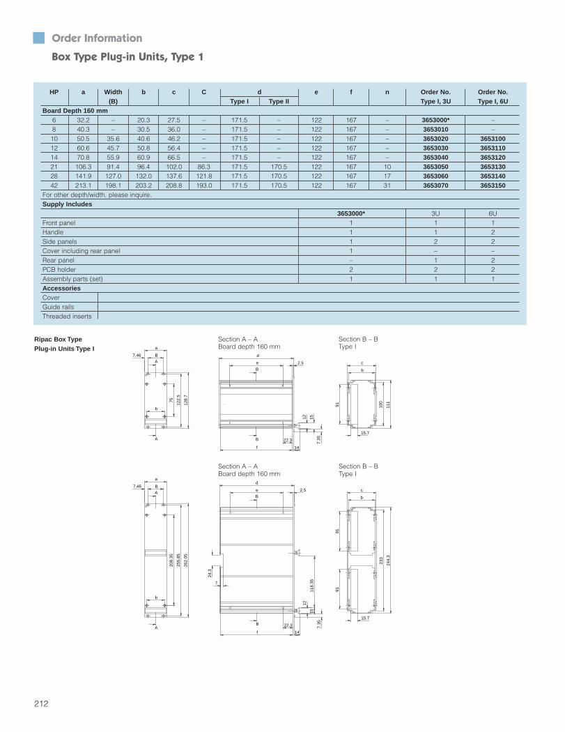
212
Order Information
Box Type Plug-in Units, Type 1
HP a Width b c C d e f n Order No. Order No.(B) Type I Type II Type I, 3U Type I, 6U
Board Depth 160 mm6 32.2 – 20.3 27.5 – 171.5 – 122 167 – 3653000* –8 40.3 – 30.5 36.0 – 171.5 – 122 167 – 3653010 –10 50.5 35.6 40.6 46.2 – 171.5 – 122 167 – 3653020 365310012 60.6 45.7 50.8 56.4 – 171.5 – 122 167 – 3653030 365311014 70.8 55.9 60.9 66.5 – 171.5 – 122 167 – 3653040 365312021 106.3 91.4 96.4 102.0 86.3 171.5 170.5 122 167 10 3653050 365313028 141.9 127.0 132.0 137.6 121.8 171.5 170.5 122 167 17 3653060 365314042 213.1 198.1 203.2 208.8 193.0 171.5 170.5 122 167 31 3653070 3653150
For other depth/width, please inquire.Supply Includes
3653000* 3U 6UFront panel 1 1 1Handle 1 1 2Side panels 1 2 2Cover including rear panel 1 – –Rear panel – 1 2PCB holder 2 2 2Assembly parts (set) 1 1 1AccessoriesCoverGuide railsThreaded inserts
Ripac Box Type Plug-in Units Type I
b
111
100
15.7
c
9191
91
b
c
15.7
233
244.
3
12
22.3
f 14
d
2.5e
7
7.35
24.3
B
B
1511
8.35
15
14
e 2.5
d
f
22.3
12
7.35
B
B
b
B7.46
a
208.
35
255.
85
262.
05
A
A
a
B7.46
b
75
122.
5
128.
7
A
A
Section A – ABoard depth 160 mm
Section B – BType I
Section A – ABoard depth 160 mm
Section B – BType I
Section 5_200-257 4/7/04 8:58 AM Page 13

213
Order Information Box Type Plug-in Units, Type 1 n
Material:Front Panel:2.5 mm aluminum, natural anodizedRear Panel:2 mm aluminum, naturalModule Sections:Extruded aluminum section, natural anodizedHandle:Aluminum, natural anodizedPCB Holder: Plastic
Box type plug-in units in specialsizes or with printing available on request.
Technical Specifications:Installation depth:160 and 220 mmHeight: 3U and 6U to DIN 41 494, part 5 Rear panel to accommodate individual connectors
Box Type Plug-in Unit, Type IStandard rear panel with cutout for connector.
Covers (Accessory)for box type plug-in units, vented orunvented, slide-in or screw fastening. Order No. see page 214.
EMC Box Type Plug-in Unitwith EMC front panel.On request.
PCB Holderfor securing PCBs.Order No. see page 216.
Section 5_200-257 4/7/04 8:58 AM Page 14

214
Accessories
Ripac Box Type Plug-in Units, Individual Components
Index Box type plug-in units, indiv. comp. Type I Type II Packs of 8 HP 10 HP 12 HP 14 HP 21 HP 28 HP 42 HPFront Panels Of 2.5 mm Aluminum, Anodized Surface Finish
For 3U • • 1 3685769 3685629 3685630 3685631 3685636 3685637 36856381 For 6U (for 1 handle) • • 1 3685767 3685633 3685634 3685635 3685639 3685640 3685641
For 6U (for 2 handle) • • 1 – 3687520 3687521 3687522 3687523 3687524 3687525EMC Front Panels Of 2.5 mm Aluminum, Surface Finish Clear Chromated (Only For Use In Conjunction With 10HP Box Type Plug-in Unit)
1aFor 3U/10HP box type plug-in unit • • 1 – – 3687587 – – – –For 6U/10HP box type plug-in unit • • 1 – – 3687588 – – – –
EMC gaskets for front panels
1bFor 3U • • 1 – – 3686975 – – – –For 6U • • 1 – – 3686977 – – – –
Handle Type VOf extruded aluminum section, • • 1 3685600 3685601 3685602 3685603 3685761 3685762 3685763
2 anodized surface finishOf plastic • • 1 3685492 – 3685493 – 3685494 – –
Identification strips
3Of 1.4 mm aluminum, • • 1 3685751 3685752 3685753 3685754 3685755 3685756 3685757anodized surface finish
Covers Of 1 mm Aluminum, Clear Chromated/1.2 mm Sheet Steel, Zinc-plated, Passivated (With Vent Slots)
4aUnvented, for board depth 160 mm • • 1 3687555 3685689 3685690 3685691 3685692 3685693 3685694Unvented, for board depth 220 mm • • 1 3687562 3685701 3685702 3685703 3685704 3685705 3685706
4bVented, for board depth 160 mm • • 1 3687585 3685683 3685684 3685685 3685686 3685687 3685688Vented, for board depth 220 mm • • 1 – 3685695 3685696 3685697 3685698 3685699 3685700Vent slots for plastic guide rails, • • 1 – 3687556 3687557 3687558 3687559 3687560 3687561
4c for card depth 160 mmVent slots for plastic guide rails, • • 1 – 3687563 3687564 3687565 3687566 3687567 3687568for card depth 220 mm
Side Panel Of Extruded Aluminum Section, Anodized3U, for board depth 160 mm • • 1 3685645
56U, for board depth 160 mm • • 1 36856483U, for board depth 220 mm • • 1 36856466U, for board depth 220 mm • • 1 3685649
Rear Panel Of 2.0 mm Aluminum, Untreated/1.2 mm Sheet Steel, Spray Finished6a For 1 connector • 1 3687536 3685707 3685708 3685709 3685710 3685711 3685712
Box Type Plug-in Units, Types I And II In 3U And 6UType I for one connector/Type II for several connectors
Type I
Type I
Section 5_200-257 4/7/04 8:58 AM Page 15

215
Accessories Box Type Plug-in Units, Type V And Type VI In 3U And 6U n
Index Box type plug-in units, indiv. comp. Type V Type VI Packs of 6 HP 7 HP 8 HP 10 HP 12 HP 14 HPFront Panels Of 2.5 mm Aluminum, Anodized Surface Finish
1For 3U • • 1 – 3685628 3685769 3685629 3685630 3685631For 6U • • 1 – 3685632 3685767 3685633 3685634 3685635
Trapezoid HandleOf extruded aluminum section, • • 1 – 3685599 3685600 3685601 3685602 3685603
2 anodized surface finishOf plastic • • 1 – – 3685492 – 3685493 –
Identification Strips
3Of 1.4 mm aluminum, • • 1 – 3685750 3685751 3685752 3685753 3685754anodized surface finish
Covers Of 1 mm Aluminum, Clear Chromated Surface FinishUnvented, 3U, for board depth 160 mm • 1 – 3685658 3685776 3685659 3685660 3685661
4aUnvented, 3U, for board depth 220 mm • 1 – 3685674 3685777 3685675 3685676 3685677Unvented, 6U, for board depth 160 mm • 1 – 3685662 3685764 3685663 3685664 3685665Unvented, 6U, for board depth 220 mm • 1 – 3685678 3685765 3685679 3685680 3685681Unvented, 3U, for board depth 160 mm • 1 – 3685650 3685772 3685651 3685652 3685653
4bUnvented, 3U, for board depth 220 mm • 1 – 3685666 3685773 3685667 3685668 3685669Unvented, 6U, for board depth 160 mm • 1 – 3685654 3685715 3685655 3685656 3685657Unvented, 6U, for board depth 220mm • 1 – 3685670 3685716 3685671 3685672 3685673
Side Panel Of Extruded Aluminum Section, Anodized3U, for board depth 160 mm • • 1 – 36856456U, for board depth 160 mm • • 1 – 36856483U, for board depth 220 mm • • 1 – 36856466U, for board depth 220 mm • • 1 – 3685649
Assembly Parts For Box Type Plug-in Units, Types I, II, V, VIDescription For installation of: Packs of Order No.Assembly kit for box type plug-in units, type I/II, 3U Box type plug-in units, type I/II, 3U 1 set 3687589Assembly kit for box type plug-in units, type I/II, 6U Box type plug-in units 16U 1 set 3687590Assembly kit for box type plug-in units, type V/VI Box type plug-in units, type V/VI 1 set 3685294Assembly kit for box type plug-in units with EMC front panel Box type plug-in units with EMC front panel 1 set 3687591Assembly kit for plastic handles Plastic handles on box type plug-in units 1 set 3687519For more screws, see pages 218-219
Type V, With Cover (Unvented)/Type VI, With Cover (Vented)
1
32 4a
5
1
32
4b
5
Type V Type VI
Section 5_200-257 4/7/04 8:58 AM Page 16

216
Accessories
Ripac Box Type Plug-in Units For Drives
Vertical Drive ChassisFor the installation of drives or CD-ROMs. May beinstalled in all Ripac subracks and special subracksfor drive chassis Optionally prepared for EMC or non-EMC Accommodation for 3-1/2" or 5-1/4" drives or
CD-ROM, vertical Front panel and support plate integratedMaterial:Front panel: 2.5 mm aluminumSupport plate: Aluminum
Surface Finish:Clear chromatedSupply Includes:1 front panel with support plate1 EMC gasket (with EMC modules)Assembly parts
Guide Rail For Drive ChassisThis ultra low profile guide rail has been developedfor rigid drive chassis in the Ripac Vario subrack fordrive chassis. 2 guide rails are required for eachdrive chassis.Supply Includes:1 guide rail including alignment pin
TE
HE
H
7.47
B
For installation depth Packs of Order No.160 mm 1 3686989
PCB Holders In Box Type Plug-in Units Type I, II, V, VIFor fastening PCBs in box type plug-in units.Material:PBT (Pocan 4235)
Packs of Order No.2 + assembly screws 3606321
Installation Front panel Approximate Front panel Order No.drives depth of drive cutout
U (HE) HP (TE) H Width (B) EMC non-EMC1 x 3-1/2" 3 8 160 20 102 3684468 3685077
3 8 160 26 102 3684469 36850783 8 160 31 102 3684470 36850793 10 160 41.5 102 3684471 3685080
1 x 3-1/2" 4 8 160 20 102 3684472 36850814 8 160 26 102 3684473 36850824 8 160 31 102 3684474 36850834 10 160 41.5 102 3684475 3685084
1 x 5-1/4" 4 10 220 41.5 147 3684476 36850852 x 3-1/2" 6 8 160 2 x 20 102 3684477 3685086
6 8 160 2 x 26 102 3684478 36850876 8 160 2 x 31 102 3684479 36850886 10 160 2 x 41 102 3684480 3685089
1 x 5-1/4" 6 10 220 41.5 147 3684481 36850901 x 3-1/2" 3 8 160 – – – 3685091
3 10 160 – – – 36850921 x 3-1/2" 4 8 160 – – – 3685093
4 10 160 – – – 36850942 x 3-1/2" 6 8 160 – – – 3685095
6 10 160 – – – 3685096
Note: Assembly screws should be ordered separately (2 assembly screws are required per guide rail) Order No.3654340, packs of 100
Section 5_200-257 4/7/04 8:58 AM Page 17

217
Accessories Ripac Box Type Plug-in Units/Installation n
Covers For Type I And II Box Type Plug-in UnitsWithout vent slots. For slide-in fastening in the boxtype plug-in units. The covers with vent slots aresuitable for the installation of plastic guide rails.Material:1.0 mm aluminum, clear chromated(cover plates without vent slots)1.2 mm sheet steel, zinc-plated, passivated(cover plates with vent slots)Note: Assembly screws should be ordered separately:Order No. 3685289, packs of 100Supply Includes:1 cover
Unit Packs of Order No. Order No.width Vented Solid
Board Depth 160 mm8HP 1 – 368755510HP 1 3687556 368568912HP 1 3687557 368569014HP 1 3687558 368569121HP 1 3687559 368569228HP 1 3687560 368569342HP 1 3687561 3685694
Board Depth 220 mm8HP 1 – 368756210HP 1 3687563 368570112HP 1 3687564 368570214HP 1 3687565 368570321HP 1 3687566 368570428HP 1 3687567 368570542HP 1 3687568 3685706
Slide-in Cover
Screw-fastened Cover
Cover Plates For Type I And II Box Type Plug-in UnitsSlide-in, with ventilation holes (EMC).Material:1.0 mm aluminumSupply Includes:2 covers
Unit Packs of Order No. Order No.width 160 mm 220 mm8HP 1 3687585 –10HP 1 3685683 368569512HP 1 3685684 368569614HP 1 3685685 368569721HP 1 3685686 368569828HP 1 3685687 368569942HP 1 3685688 3685700
Guide Rails For Type I And II Box Type Plug-in UnitsFor guiding several PCBs in a single box type plug-in unit. May be installed in covers with vent slots.Material:Noryl
For PCB Packs of Order No.thickness 1.6 mm
160 mm 10 3606140220 mm 10 3606200
Threaded Inserts For Box Type Plug-in Units Type I, II, V, VIFor securing accessories to the outside of the module side panel. The threaded inserts slide into the side section and the assembly is fastened with M2.5 set screws,Order No.RP 3687020.Material:SteelSurface Finish:Zinc-plated, passivated
Module depth Packs of Order No.160 mm 4 3653600220 mm 4 3653610
Section 5_200-257 4/7/04 8:58 AM Page 18

218
Assembly Parts
For the attachment of: Dimensions Description Order No. Packs of Order No.Packs of 1
Front panels to unit side panels M3 x 8Panhead csk-screw ISO
3606550 100 36858267047-4.8-Z-A2F
Rear panels to box type plug-in units M3 x 8Panhead screw ISO
3606560 100 36858257045-4.8-Z-A2F
PCB holders (plastic) to front panel, top M2.5 x 10Panhead csk-screw ISO
3606610 100 36858317047-4.8-Z-A2F- Horizontal rails to side panels Panhead self-locking- Divider panels to horizontal rails M4 x 12 screw similar to DIN ISO 3654300 100 3684881- Horizontal rails to vertical supports 7045-8.8-Z-A2F- PCBs to PCB holder
Panhead screw(die-cast with 3U), top M2.5 x 8ISO 7045-4.8-Z-A2F
3654320 100 3685828- PCBs to extractor handles with 6U- PCB holders (plastic) to type V/VI handles,
Panhead screwbottom M2.5 x 10ISO 7045-4.8-Z-A2F
3654330 100 3685830- PCBs to PCB holders (plastic)- Connectors to Z rails- Z rails to horizontal rails
Panhead screw- Type V/VI handles to partial front plates, M2.5 x 6ISO 7045-4.8-Z-A2F
3654340 100 3685827bottom right for > = 5HP
- Aluminum guide rails to horizontal railsAluminum guide rails to horizontal rails
M2.5 Retaining cage 9901417 100 9901398(fastening of square nuts)Type V handle (plastic) to front panels Mounting kit for handles
type V (plastic) 3687519 1 setCover black – 3687584Cover gray – 3687582
M2.5 Hex nut – 3685834M2.5 x 16 Screw – 3687583M2.5 x 12 Screw – 3685833
M2.5 Square nutDIN 502-11H-A2F – 3685955
Connectors to PCBs (IEC 60603) M2.5 x 12Panhead screw ISO
3654350 100 36858337045-4.8-Z-A2F
Guide rails (plastic) to horizontal rails M2.2 x 6Screw for plastic
3654360 100 3685838WN 1413- Flat front panels to handles type V, VI
M2.5Square nut
3654370 100 3685955- Aluminum guide rails to horizontal rails DIN 562-11H-A2F
Flat front panels to horizontal rails M2.5 x 11Collar screws (cheese-
3658160100
–head) and plastic collars sets
Plastic collars 3687021 100 3685837
M2.5 x 11 Collar screws (cheesehead) 100 3685832
PCB to type III handle 3.0 x 8Screw for plastic
3658190 100 3686035WN 1412- PCBs to PCB holders (plastic)
M2.5Hex nut
3658210 100 3685834- PCB holders to front panels, top ISO 4032-8Backplanes to threaded inserts Mounting kit for backplanes: 3684019 100 –
2.7 - Washer, PE natural DIN 125 – 3685835
Covers to mounting blocks M3 x 6Csk-screw
3684233 100 3684883ISO 7046-1-4.8-Z-A2F
Covers to side panels Mounting block 3684234 10 3684884
Type V/VI handles to front panels Bracket 3684435 100 3685760
Female connector to PCB attachment 2.5 x 0.3 x 10 Pop rivet DIN 7340-B-CuZn 3684482 100 3685836
Section 5_200-257 4/7/04 8:58 AM Page 19

219
Assembly Parts
For the attachment of: Dimensions Description Order No. Packs of Order No.Packs of 1
Type V handles (plastic) to front panels Baying kit 3687519 1 set –
Fans to fan mounting plate/rear panel Mounting kit for fans: 3685197 4 set –
M4 x 12- Panhead screw
– 3685969ISO 7046-1-4.8-Z-A2F
M4- Hex nut
– 3685809ISO 4032-8
4.3- Serrated washer
– 3685808DIN 6797-A-Fst
Covers to side panels Mounting kit for cover plates: 3685256 24 sets –
Mounting block 3684234 10 3684884
M3 x 6 - Csk-screw ISO 7046-1-4.8-Z-A2F 3684233 100 3684883
PCB holder (die-cast) to front panels, top M2.5 x 8Panhead csk-screw DIN
3685282 100 3685829ISO 7047-8.8-Z-A2F- Covers/box type plug-in units type I/II
M2.5 x 5 Csk-screw ISO 7046-1-4.8-Z-A2F 3685289 100 3685954- Contact/spring sections for 3-part front panels- Handles on front panels for box type
plug-in units M2.5 x 6 Csk-screw ISO 7046-1-4.8-Z-A2F 3685290 100 3685953- Front panels to hinge strip
To join two 4HP extractor handles, type IV 2 x 20 Cylinder pin ISO 2338-A-St 3685319 20 3686935
Holder (horizontal assembly kit),M2.5 x 5
Csk-screw similar to DIN 3686916 100 3686914for backplane installation to horizontal rail ISO 7046-1-4.8-Z-A2F
- Holder (horizontal assembly kit), M2.5 x 8 Csk-screw similar to DIN 3686917 100 3686915for horizontal rail
ISO 7046-1-4.8-Z-A2F- Vertical supports to horizontal railsSpring and contact sections on 3-part
M2.5 x 5Panhead screw DIN
3686924 100 3686923front panels without countersink ISO 7046-4.8-Z-A2FRecessed flanges to side panel Mounting kit for recessed flanges: 3687015 4 sets –
- Panhead self-locking M4 x 8 screw similar to DIN ISO – 3684882
7045-8.8-Z-A2F
M4 - Hex nut ISO 4032-8 – 3685809
4.3 - Washer – 200611
Fastening the threaded insertsM2.5 x 8 Grub screw ISO 7434-14H 3687020 100 3686015in horizontal rails
Front panels to horizontal rails Plastic collars 3687021 100 3685837
EMC front panels to horizontal rails M2.5 x 11 Centering screw, slotted 3687050 100 3686002
EMC front panels to horizontal rails M2.5 x 11 Centering screw, posidrive 3687051 100 3686001
Front panels to horizontal rails M2.5 x 11 Collar screw, cheese-head 3685097 100 3685832
Type V/VI handles (aluminum) to front panels Mounting kit for type V/VI handles 3687146 1 set –
- Panhead screw M2.5 x 6 ISO 7045-1-4.8-Z- 3654340 100 3685827
A2F
- Bracket 3685625 50 3685760
M2.5- Square nut
3654370 100 3685955DIN 562-11H-A2F
Section 5_200-257 4/7/04 8:58 AM Page 20

Product Diversity Knowledge Transfer MPS Expertise Globalization Integrative Thinking
Supercool, Hot Swappable RiCool System BlowerCool Solutions. . .
220
Section 5_200-257 4/7/04 9:03 AM Page 21
19 Plants, 40 Subsidiaries
Over 8,000 Standard Products
Involvement In Standardization Bodies
And Much More
Cool Off With RiCool.Kaparel/Rittal Ripac has literally set the standard for
CompactPCI packaging solutions. And our new RiCool Blower
Assembly helps to keep the innovations coming. These super-
cool, hot swappable blowers deliver 220cfm system airflow at
70% efficiency (versus 20% when using typical 4.7" tubeaxial
muffin fans) in only a 1U form factor. RiCool is an ideal solution
for systems with PCBs exceeding 35W to 70W (average at 21
slots) heat loss and requiring a hotplug redundant blower. In
addition, Kaparel/Rittal also offers a wide variety of conventional
AC and DC fan solutions for applications which do not exceed
30W (average at 21 slots) heat dissipation. So when things heat
up, cool them off with Kaparel/Rittal Ripac cooling solutions.
Kaparel/Rittal RipacRiCool Blower Assembly
RiCool-1 Data And Specifications . . . . . . . . . . . . . . . . . . . . . . . .222
RiCool-2 Data And Specifications . . . . . . . . . . . . . . . . . . . . . . . .224
Conventional AC/DC Tubeaxial Muffin Fan Cooling
Conventional AC/DC Fans . . . . . . . . . . . . . . . . . . . . . . . . . . . . .226
RiTherm Thermal Analysis System
Thermal Load Boards And System . . . . . . . . . . . . . . . . . . . . . . .228
221
Section 5_200-257 4/7/04 9:03 AM Page 22

222
Cooling For VME64x/CompactPCI
RiCool-1 Blower 110cfm (190m3/h)
The powerful RiCool-1 blowers havebeen designed to provide effectivecooling for CompactPCI systems whichrequire a redundant cooling featureand/or have a heat dissipation of over 500W.The ability of the RiCool-1 blower togenerate 1.6"/40.64mm (H2O) of staticpressure confirms that the RiCool-1blower is able to provide effectivecooling in a densely packed CompactPCI system.By comparison, a typical systemcooled with three 4.7" x 4.7" 18W(110cfm at free delivery) muffin fans,generates only 0.22" to 0.40" (H2O)static pressure point of a muffin fanassembled, fully loaded CompactPCIsystem is 0.3" to 0.5" (H2O). Underthose conditions one RiCool-1 blowerprovides at least 40% higher airflow.
Each 19" CompactPCI system canaccept two RiCool-1 blowers.
Electromagnetic Emissions For RiCool-1 BlowersThe RiCool-1 blowers comply with theEMI Standard per FCC part 15, sub-part J of Docket 20780, Class A & Bemissions limit across the frequencyspectrum from 30MHz to 1GHz.
SafetyRiCool-1 is in conformity with therequirements of the Low VoltageDirective, Nr. 73/23/EEC EN 60950:1992 +A1 +A2 +A3 +A4 +A11.
Features And Benefits Uses only 1U of rack height Available in 12V, 24V and 48V dc Fan alarm via fan speed sensor Optional speed control Designed to move air effectively
through densely packed subracks Easy access Hot swapable for fast and easy
maintenance Ability to use two blowers in 19”
applications Locked rotor protection Polarity protection Automatic restart capability
ConfigurationMaterial: clear zinc chromate steelhousingIncludes: complete fan assembly:ready for mounting in subrack, withMolex 15-06-0061 6 pin male mini-fitconnectorAirflow Direction: exhausts outwardfrom back of subrack
Power Consumption: 48WOperating Temperature:-10°C to +60°C / +14°F to +140°F
RiCool-1 Blower Performance Datacfm: 110cfm(190m3/h)Static Pressure: 40.64mm (1.6 inch) of H2OVoltages: 12, 24, 48V dcRated Current: 4, 2, 1 AmpsNoise Level Free Blowing: 56.2dBaWeight: 5 lbs. (2.3 Kg)
RiCool-1 Blower ConstructionHousing: cold rolled steelImpeller: Noryl™ 94V0Bearing: ball bearingPower/alarm connector:Molex15-06-0061Alarm Signal: rpm sensorLife At Full Speed:60,000 hrs @ 40°C50,000 hrs @ 50°C
Please inquire for separate AC/DCRiCool-1 power supply.
RiCool-1 is also available in 19” blower trays (see above photo).Please note that the airflow, powerconsumption, rated current and weightare double for the 19” fan trays. For more information, please contactthe factory.
.4
0 20 40 60 80 100 120
.8
1.2
1.6
Performance diagram3344.012/.024/.048
Pst
Pst
V
VStatic pressure difference (inches of H2O)
Air displacement (cfm)
Typical performance diagram of tubeaxial muffin fans
Typical performance diagram of RiCool
.3
File No. E191011
Section 5_200-257 4/7/04 9:03 AM Page 23

223
Cooling For VME64x/CompactPCI n RiCool-1 Blower 110cfm (190m3/h)
Alarm Characteristics Pin #3 inverted alarm, max load of
0.05A at 60V DC Pin #6 non-inverted alarm, max load
of .015A at 5.5V DC Trigger speed at 40% of max speed 10 second signal delay Alarm condition causes +5V DC
increase in supply voltage measuredbetween pin #3 and pin #1
Customer supplied pull-up resisterat interfacing alarm required to limitcurrent to blower alarm circuit
RiCool-1 Blowers
Description Qty Order No.RiCool-1 blower 12V 1 3344012RiCool-1 blower 24V 1 3344024RiCool-1 blower 48V 1 3344048RiCool-1 blower 48V 1 3688063
with internal thermistors
44.40
4.20
4.20
8.40
13.4
6.9
Connector Detail
(209.560)
LargeAir Intake
8.250
(209.560)8.250
(43.1)1.70
Front View(209.560)
Top View
18.75 diam. Extraction holes
®
Air flow
(13.437).529
Rear View
(209.560)
(43.1)1.70
46.5
3 2 1
6 5 4
Pin #3, inverted alarm (blue-low on pass)
Pin #2, program speed control (yellow)
Pin #1, second ground (green)
Pin #4, power (-) (black)
Pin #5, power (+) (red)
Pin #6, non-inverted alarm (blue/white-high on pass)
Air exit
Temperature/Speed Control Thermistors
Description Qty Order No.PTC thermistor for 12V 1 3686887PTC thermistor for 24V 1 3686888PTC thermistor for 48V 1 3686889
Note: The thermistors come with a 600mm (2') cable
RiCoo-1l Hot Plug Connector
Description Qty Order No.6 Pin Molex RiCool-1 1 Part of RiCool
mounted receptacle 15-06-00616 Pin Molex cPCI system 1 9810117mounted plug 15-06-0065
Pin Location Description
Pin #1, second motor ground(green)Pin #2, program speed control (yellow)Pin #3, inverted alarm (blue-low on pass)Pin #4, power (-) (black)Pin #5, power (+) (red)Pin #6, non-inverted alarm(blue/white-high on pass)
Section 5_200-257 4/7/04 9:03 AM Page 24

224
Cooling For VME64x/CompactPCI
RiCool-2 Blower 180cfm (300m3/h)
RiCool-2 is a follow-on developmentto the highly successful RiCool-1blower
RiCool-1 was primarily designed forCompactPCI and VME systems withheat loss from 30W to 70W per slot(21 slots)
RiCool-2 is primarily designed froAdvancedTCA systems with a heatloss of 200W per slot (14 slots)
Uses only 1U of rack height Initially available in 48V, followed by
12V and 24V Designed to move air effectively
through densely packed subracks Hot swappable for fast and easy
access/maintenance Ability to use 2 or 4 blowers in a
19" application For indoor applications
Mechanical:Housing: stainless steelWeight: 1.72Kg (3.8 lbs)Conductive Surface:recycling per EN 60730Base Tray: 1.5mm (16 gauge)Cover: 0.8mm (18 gauge)Wheel: polycarbonate, black, UL 94-V0Connector:Version 1: Molex 15-06-0061Version 2 and 3: DIN 41612 Type C, 30 pin
Temperature Range:Operating Temperature:-10°C – +75°CStorage Temperature:-40°C – +80°C
Humidity: 0 to 95% RH, non-condensingNoise:65dB (A) at full speed, free blowing55dB (A) at 70% speed, free blowing
MTBF:Life At Full Speed:60,000h at 40°C50,000h at 50°C>35,000h at 70°CHigher MTBF at 70% of full speed at40°C expected under normal operatingconditions.
Performance: 180cfm (300m3/h) High static pressure at zero flow of
2.8 – 3.0 inch (71mm) H2O; idealwhen air filters are used (typicalmuffin fans have 0.3 – 0.4 inch H2O)
Service Friendly Field Replaceableunit (FRU) design
Hot Swap, redundant design Optional configurations:
• RiCool-1 minimum control functions
• PICMG 2.9 compatible controlfunctions
• PICMG 3.0 IPMI compatible control functions
COTS (Commercial Off The Shelf)12V, 24V and 48V solutions
48V now available, 12V and 24Vplease inquire
.4
0 20 40 60 80 100 120 140 160 180
.8
1.2
1.6
1.8
2.0
2.2
2.6
2.8Performance diagram
Pst
Pst
V
VStatic pressure difference (inches of H2O)
Air displacement (cfm)
Typical performance diagram of tubeaxial muffin fans
Typical performance diagram of RiCool-1Typical performance diagram of RiCool-2
.3
Section 5_200-257 4/7/04 9:03 AM Page 25

225
VME64x/CompactPCI n RiCool-2 Blower 180cfm (300m3/h)
RiCool-2 Version 3 Connector Connector Pin-Out For Version 3
Motor Specifications:Nominal Voltage: 48 VDC (12 VDCand 24 VCD optionally available)Operating Voltage Range:48 VDC = 36-72 VDCLow Start Voltage: 32 VDCNominal Running Current:48V/1.7 AmpsStart Current: ramps to any desiredset-pointLocked Rotor Current: 2.1 AmpsNominal Running Power: 80 WattsNominal Speed: 4500 rpm +/-10%(free delivery)Start Up Time: 15 sec. MaxMotor Type: brushless DCMotor Protection:by integrated circuit, fuseBearings: permanently lubricated ballbearingsAir Flow: 160cfm min 180cfm maximum at full powerAcoustic: 65 dBA at full power, 55 dBA at 70% of full powerLocked Rotor Protection: electronicPolarity Protection: yesAutomatic Restart Capability:integrated circuit
Version 3 Features: Polarity protected Locked rotor protection Automatic restart Programmability On board thermistor Input fusing Over temperature alarm LED Red LED Blue Toggle switch Temperature sensor Flame sensor Dual power input The RiCool-2 blower will have the
means to detect a failure in thebase management controller (BMC)and/or management application(MA). Upon detecting a failure, the blower will revert to a self sustaining mode of operation.
Sensors (thermistors, hall-effectswitches, voltage, etc.) will supportall of the sensor device commandsderived by the BMC. Sensor devicecommands are defined in section3.0 of PICMG 3.0.
Base Tray Mounted PCB Includes: All basic motor controls Mezzanine control board connec-
tions Thermistor located in outlet air
stream Temperature sensor Flame sensor 1 LED red for fail per PICMG 3.0 1 LED blue for hot swap removal
per PICMG 3.0 1 toggle switch for hot swap
removal per PICMG 3.0 PCB is designed for 48V/24V/12V
blower applications
Regulatory Compliances: UL recognized per category
CPWV2: fans, electric components CUL recognized per category
CPWV8: fans, electric cert. Canada TUV certified to EN 60950 CE mark to comply with:
Maschinernrichtlinien 89/392EWG Niederspannungsrichtlinien73/23/EEC
FCC part 15, subpart J of Docket20780, Class A & B radiated andconducted emissions spectrumfrom 30MHz to 1GHz
Physical protection when installed,IP20 EN 60335-2-40 (safety of electrical equipment) EN 60201(safety of electrical machines)
Version 2: PICMG 2.9 system management bus (SMBus) compatible
Version 1: RiCool-1 compatible(with improved airflow performance)
Version Compatibility VDC Qty Order No.3 PICMG 3.0 48 1 36882972 PICMG 2.9 48 1 inquire1 RiCool-1+ 48 1 inquire1 RiCool-1+ 24 1 inquire1 RiCool-1+ 12 1 inquire
1. A1 Motor Power +/-(1)2. A2 N/C (2)3. A3 48V_B (2)4. A4 N/C (2)5. A5 GND (1)6. A6 GA7 (2)7. A7 IPMB Power (2)8. A8 GA5 (2)9. A9 IPMB Power (2)10. A10 GA2 (2)11. B1 Motor Power +/-(1)12. B2 N/C (2)13. B3 48V_A (2)14. B4 N/C (2)15. B5 Flame Sensor (2)
16. B6 GA6 (2)17. B7 12C Data 1(2)18. B8 GA4 (2)19. B9 12C Data 0 (2)20. B10 GA1 (2)21. C1 Enable A (3)22. C2 Enable B (3)23. C3 N/C (2)24. C4 FPS Ground (1)25. C5 IPMB Enable (3)26. C6 GND (2)27. C7 12C Clock 0 (2)28. C8 GA3 (2)29. C9 12C Clock 0 (2)30. C10 GA0 (2)
30 1
C
DIN 41612-Type C – 30 Pin
B
A
Section 5_200-257 4/7/04 9:03 AM Page 26

226
Dimensions A B Bearing Rated voltage Voltage Wattage Noise Temperature Volume flow Packs of Order No.(mm) of fan V (DC) range volt level dB (A) range °C in m3/h
80 79.5 71.5 Ball bearing 12 8.0-14.0 2.2 34 – 20...+ 65 65 1 368664980 79.5 71.5 Ball bearing 24 21.6-26.4 2.4 36 – 20...+ 65 65 1 3686650120 119.0 104.8 Ball bearing 12 8.0-12.6 5.4 45 – 20...+ 65 65 1 3686647120 119.0 104.8 Ball bearing 24 21.0-27.0 5.4 45 – 20...+ 65 65 1 3686648
Accessories
Fan
AC FanFor subracks and microcomputer systems.Supply Includes:1 fan without connection cable
Note: Assembly parts must be ordered separately. Order No. 3685197, packs of 1 set (4 assembly screws)
Cable length Packs of Order No.610 mm (UL) 1 3686658
1000 mm 1 3686659
DC FanIncluding temperature-dependent speed control viaadditional temperature sensor.Supply Includes:1 fan with connection cable (310 mm)
Note: Assembly parts must be ordered separately. Order No. 3685197, packs of 1 set (4 assembly screws)
4.3
7
38AB
Dimensions A B Bearing Rated voltage Wattage Noise Temperature Volume flow Packs of Order No.(mm) of fan V (AC) / Hz level dB (A) range °C in m3/h
80 79.5 71.5 Ball bearing 115/60 11.0 42 – 40...+ 95 57 1 368664580 79.5 71.5 Ball bearing 230/50 12.0 37 – 40...+ 90 48 1 3686646120 119.0 105.0 Ball bearing 115/60 18.0 51 – 40...+ 90 180 1 3686643120 119.0 105.0 Ball bearing 230/50 19.0 47 – 40...+ 85 160 1 3686644
4.3
2232
310
AB
AC fan
DC fan with speed control and alarm signal
Dimensions A B Bearing Rated voltage Voltage Wattage Noise Temperature Volume flow Packs of Order No.(mm) of fan V (DC) range volt level dB (A) range °C in m3/h
80 79.5 71.5 Ball bearing 12 8.0-15.0 1.8 34 – 20...+ 75 75 1 368761280 79.5 71.5 Ball bearing 24 12.0-28.0 2.1 34 – 20...+ 75 75 1 3687613120 119.0 104.8 Ball bearing 12 6.0-15.0 2.6 39 – 20...+ 75 75 1 3687614120 119.0 104.8 Ball bearing 24 12.0-28.0 2.6 39 – 20...+ 75 75 1 3687615
DC fan without speed control, with alarm signal
Section 5_200-257 4/7/04 9:03 AM Page 27

227
Accessories n Fan
Temperature Sensor
M
Finger Guard
Voltage Packs of Order No.12 V (DC) 1 368665724 V (DC) 1 3686657
For fans with speed control.Supply Includes:1 temperature sensor
For AC/DC fans.Material:Polyamide self-extinguishing to UL 94-VOColor:BlackSupply Includes:1 finger guard
4.3
RC
R(NTC)
For fans Packs of Order No.80 mm 1 3686656120 mm 1 3686655
EMC Shielding PlateFor AC/DC fans.Material:1 mm aluminumSurface Finish:Clear chromatedSupply Includes:1 EMC shielding plate
For Fans Packs of Order No.80 mm 1 3686359120 mm 1 3686329
+ Power supply
- EarthTemperaturesensorAlarm signal(optional)
Typ
e 10
/Typ
e 17
Alarm signal
Alarm power supply
+ Motor
- Motor
Temperature sensor
Finger guardRear panel
EMC filter guard
Fan
Section 5_200-257 4/7/04 9:03 AM Page 28

228
Order Information
Rack-Mounted Fans For 482.6 mm (19") Air Throughput 320/480 m3/h n
1
2
2
20621
4 432
120
55
482.6 (19″)
426
43.6
(1
HE
)
85/1
05
Two basic types provide universal applications,both for the ventilation of individual subracksand for enclosures and cases.Technical Description Rack-mounted Fans: Versions with a distance between axis
– of 85 mm for 160 mm deep PCBs and– of 105 mm for 220 mm deep PCBs
Fan unit with speed control SK 3342.500:with fault evaluation via floating contact
Technical Description Vario Rack-mounted Fan: Via an additional guide frame, may
be used in: – Subracks 84HP – 482.6 mm (19") mounting angles
The guide frame offers a high level offlexibility, i.e. simply slide in the fan insert, lock into position
Tapped strips inserted in the guide frameensure variable positioning of the fan insert in the subrack
Pre-configured connectors ensure secure, problem-free inter-connection
Fan unit with speed control SK 3352500Fault evaluation via floating contact
Supply Includes:Rack-mounted fan/Vario rack-mounted fan:Fully wired unit ready for connection,including terminal strip and assembly parts.
410
73100
482.6 (19″)
18020
0
43.6
(1
HE
)
85/1
05
Rack-mounted FanMay be fitted to 482.6 mm (19") mounting angles
Vario Rack-mounted FanBy means of additional guide frame,may be used in: Subrack 84HP 482.6 mm (19") mounting level
Mounted between a pair of 482.6 mm (19") -mounting angles
LED display(version with monitoring
HE = U
Mounted in subracks 84HP
LED display(version with monitoring HE = U
Mounted between a pair of 482.6 mm(19") -mounting angles
SK Rack-mounted Fan Vario SK Rack-mounted FanOrder No. SK Order No. SK
2 fansDistance between axes 85 mm
33400241) 33401151) 3340230 – 33500241) 33501151) 3350230 –
3 fansDistance between axes 85 mm
33410241) 3341115 3341.230 – 33510241) 33511151) 3351230 –
3 fansDistance between axes 105 mm
3342024 33421151) 3342230 33425002) 33520241) 33521151) 3352230 33525001)2)
Rated operating voltage Volt24 V (DC) 115 V (AC) 230 V (AC) 24 V (DC) 24 V (DC) 115 V (AC) 230 V (AC) 24 V (DC)
115-230 V 115-230 V (AC) (AC)
Matching guide frame – – – – 33561001) 3355100 3355100 33571001)1) Delivery times available on request 2) Version with monitoringAccessoriesTemperature indicator 230 V (AC) 3114024 3114115 3114100 3114024 3114024 3114115 3114100 3114024Thermostat 3110000 3110000Speed control 3120000 3120115 3120000 – 3120000 3120115 3120000 –
Technical SpecificationsOrder No. SK 3340230 3340115 3340024 3341230 3341115 3341024 33425002)
3350230 3350115 3350024 3351230 3351115 3351024 33525002)3342230 3342115 33420243352230 3352115 3352024
Rated operating voltage AC 230 V AC 115 V DC 24 V AC 230 V AC 115 V DC 24 V DC 24 VAC 115-230 V
Frequency 50/60 Hz 50/60 Hz - 50/60 Hz 50/60 Hz - 50/60 HZRated current 0.24 A/0.22 A 0.46 A/0.46 A 0.49 A 0.36 A/0.33 A 0.69 A/0.69 A 0.74 A 0.85 APre-fuse T 6 ANumber of fans 2 3Air throughput, unimpeded air flow 320 m3/h 480 m3/hOperating temperature - 10˚C to + 55˚CNoise level 51 dB (A) 52 dB (A) 51 dB (A) 51 dB (A) 52 dB (A) 51 dB (A)
Section 5_200-257 4/7/04 9:03 AM Page 29

229
Order Information
Air throughput 320 m3/h 480 m3/h
Voltage24 V
115 V 230 V 24 V (DC) 115 V 230 V24 V (DC)
(DC)115-230 V
(AC)No. of fans 2 3Distance between axis 85 mm 105 mm 85 mm 105 mm 85 mm 105 mmOrder No. 3340024 3340115 3340230 3341024 3342024 3341115 3342115 3341230 3342230 3342500SK rack-mounted fan
Order No. 3350024 3350115 3350230 3351024 3352024 3351115 3352115 3351230 3352230 3352500Vario rack-mounted fanOrder No. Matching 3356100 3355100 3356100 3355100 3357100Guide frame for Vario SK
Guide Frame Supply Includes:Guide frame including connector andfitted connection cable (3 m), bracketfor optional attachment to the 482.6 mm(19") system, assembly parts.
Note: Rack-mounted fan with 48 Vavailable on request
Also Required:Order a guide frame to suit the application.Approvals for all rack-mounted fans, CE compliant
Section 5_200-257 4/7/04 9:03 AM Page 30

Product Diversity Knowledge Transfer MPS Expertise Globalization Integrative Thinking
Diversity In Perfection. Instrument Cases/System Enclosures
230
Section 5_200-257 4/7/04 9:04 AM Page 31

19 Plants, 40 Subsidiaries
Over 8,000 Standard Products
Involvement In Standardization Bodies
And Much More
231
As well as the classic Kaparel/Rittal
instrument case, with its numerous
application benefits, the RiCase
instrument case will also impress you,
with its modern design in numerous
colour variants and, above all,
its all-metal enclosure construction.
The Ripac Vario-Module system
enclosure is fully compatible with the
latest Ripac subrack range, making it
ideal for individual installation and
configuration as a microcomputer
system. All in all, the design and
function of this range are sure
to impress.
RiBoxSystem enclosure for the horizontal installationof single boards or the installation of routers,hubs and modems.
Ripac Vario-Module Shown left as an instrument case in 7U. The 6U subracks are cooled diagonally. The fans are located on the rear panel.Optionally also as a rack-mounted enclosure.
RiCaseThe modular all-metal enclosure is a perfect“safe” for valuable electronics. The styling and colour add innovative design touches,emphasizing the value of the electronics within.
Section 5_200-257 4/7/04 9:04 AM Page 32

232
Overview Of System Enclosures And Instrument Cases
RiBox Ripac Vario-Module
ApplicationsSystem enclosure for use as instrument case or as a rack-mountedenclosure. For the installation of Euroboards and double Euroboards(horizontal), bridges, hubs, routers or modems.
ApplicationsSystem enclosure for use as instrument case or as a rack-mountedenclosure. For the installation of PCBs and board type plug-in units.Suitable for mobile and non-mobile applications.
User Benefits Minimum space requirements of just 1U Simple and fast assembly May easily be changed from instrument case to
rack-mounted enclosure EMC upgradable Individual finishing to customer wishes
User Benefits May easily be changed from instrument case to
rack-mounted enclosure EMC upgradable Depth-variable interior installation Wide range of accessories Neutral design
Design Features 482.6 mm (19") system enclosure to IEC 60 297-1 Optional use as instrument case or rack-mounted enclosure Height: 1U/2U Installation width: 84HP Optionally includes a mounting kit for installing a double Euroboard Mounting plate (accessories) for individual population Extruded aluminum section Protection category IP 40
Design Features 482.6 mm (19") system enclosure to IEC 60 297-1 Optional use as instrument case or rack-mounted enclosure Heights: 1 - 8U Installation widths: 42, 63, 84HP Depths: 250 - 370 mm Protection category IP 40 Extruded aluminum section Depth-variable interior installation
System EnclosuresOrder No. see page 234.
System EnclosuresOrder No. see pages 238-247.
Section 5_200-257 4/7/04 9:04 AM Page 33

233
Overview Of System Enclosures And Instrument Cases
RiCase
ApplicationsInstrument case for the installation of 482.6 mm (19") slide-in equipmentand components. Suitable for mobile and non-mobile applications.
User Benefits High level of stability Optionally as Tower enclosure 3 colors as standard Ergonomic handle, feet and door variants For mobile and non-mobile use
Design Features Instrument case to IEC 60 297-3 Heights: 1 - 12U Installation widths: 269.2 mm (1/2 19") and 482.6 mm (19") Depths: 300 - 540 mm Protection category IP 40 Extruded aluminum section Symmetrical design Depth-/height-variable interior installation
Instrument CasesOrder No. see page 252-261.
Section 5_200-257 4/7/04 9:04 AM Page 34

234
Order Information
RiBox System Enclosures 1U/2U
Order No. 482.6 mm (19") rack mount Order No. 482.6 (19") rack mountincluding mounting kit for double Euroboards
U 1 1 1 1 1 – –Width (B) mm 482.6 (19") 482.6 (19") 482.6 (19") 482.6 (19") 482.6 (19") 482.6 (19") 482.6 (19")Depth (T) mm 150 200 250 300 350 250 350Order No. 3687814 3687815 3687816 3687817 3687818 3684072 3684073Supply IncludesSide panel 2 2 2 2 2 2 2Front panel 1 1 1 1 1 1 1Rear panel 1 1 1 1 1 1 1Base/cover tray 2 2 2 2 2 2 2Mounting kit - - - - - 1 1
Order No. desktop housingU 1 1 1 1 1 - -Width (B) mm 447 447 447 447 447 - -Depth (T) mm 150 200 250 300 350 - -Order No. 3687819 3687820 3687821 3687822 3687823 - -Supply IncludesSide panel 2 2 2 2 2 - -Front panel 1 1 1 1 1 - -Rear panel 1 1 1 1 1 - -Base/cover tray 2 2 2 2 2 - -AccessoriesEMC set 3684080 3684080 3684080 3684080 3684080 3684080 3684080Mounting plate 3684074 3684075 3684076 3684077 3684078 – –
437
466.3
T
482.6 (19″)
447 T1 = T — 7
13.4
HE
34.52.9
40.9
44.1
13.4
437
447
T
T1 = T — 7
482.6 mm (19") Rack Mount
Desktop Housing
19" RiBoxU 2 2 2 2 2# of cPCI or VME slots 3 3 3 3 3Width mm 447 (17.64") 447 (17.64") 447 (17.64") 447 (17.64") 447 (17.64")Depth mm 150 (5.91") 200 (7.87") 250 (9.84") 300 (11.81") 350 (13.78")Order No. 1 pc. 3689044 3689045 3689046 3689047 3689048Finish Clear chromated, conductiveFor the desktop version of the RiBox (same Width(W) and Depth(D) dimensions), please contact the factory. If recessed or flexible 19" rack mounting flanges are required, please contact the factory.
Section 5_200-257 4/7/04 9:04 AM Page 35

235
Order Information RiBox System Enclosures 1U/2U n
Minimal space requirement of just 1U
Designed as either a desktop orrack unit
Individual finishing to customerwishes
Simple assembly with only 4screws
EMC upgrades available
The housing system RiBox wasdesigned for the horizontal mounting ofsingle boards and board type plug-in units, and for the installation of routers, hubs or modems.
Technical Specifications:System enclosures 1U/2U, 150/200/250/300 or 350 mm deepEasy to assemble with just 4 screwsOptionally for use as an instrumentcase or rack-mounted enclosureFront panel to hold a cover film to conceal the screwsMaximum possible interior useful spaceOptional EMC upgrades with additionalEMC gasketsOption of installing 1 VME orCompactPCI board horizontally or 1U
Mounting Kit And Plate of sheet steel for individual installations.Order No. see page 234.
EMC SetOrder No. see page 234.
Horizontal Circuit-board Mounting.
Material/Surface Finish:Side Panels:Extruded aluminum section, untreatedBase/Cover Trays: Aluminum, clear chromatedFront/Rear Panel: Extruded aluminum section, clear chro-matedMounting Plate: Sheet steelSystem enclosure 1U/2U to IEC 60 297-1.Optionally available for rack-mounting in the enclosure or as aninstrument case version.
Section 5_200-257 4/7/04 9:05 AM Page 36

236
In Detail:
System Enclosure Ripac Vario-Module
The ideal enclosure solution for variable applications. The Ripac Vario-Modulesystem enclosure can be used either as an instrument case or rack-mountedenclosure, due to the installation of corner trims or 482.6 mm (19") flanges in thefront section, which allow it to be adapted to suit existing applications.
Design Features
Front Corner Trim Piecefor configuration as an instrument case.
Front Flangesfor configuration as a rack-mountedenclosure.
Variable Interior Installationwith system components from theRipac subrack range.
Basic EMC Protectiondue to the all-metal enclosure with conductive contact points.
EMC Expansion Flangesand corner trim panels prepared forthe installation of EMC gaskets.
PE Conductor Setfor connecting the cover plates/gland plates to the side panels withProtective Earth conductors.
Support Stand/Carrying Handleto fit all 3, 4 and 6U enclosures.Adjustable on a 30 ° angle.
Rear Adjustable Feet may be retro-fitted. They providemechanical protection for the connectionelements and allow power cables to bewound up during transportation.
Front Handlesfor mounting on the flanges (with mounting holes).
Microcomputer Packaging Systemwith a backplane and power supplyunit, the Ripac Vario-Module is easilyupgraded to a complete MPS system.
Keyboard Lid 4U, 84HPfor retrospective, front mounting on4U high, 84HP wide enclosures.Prepared to accommodate mechanical or membrane keyboards.
Acrylic Front Doorshorizontally hinged to protect theinstalled control components.
Section 5_200-257 4/7/04 9:05 AM Page 37

Product Diversity Knowledge Transfer MPS Expertise Globalization Integrative Thinking
Product Information System Enclosure Ripac Vario-Module
May be used as an instrumentcase or rack-mounted enclosure
Basic EMC protection, thanks toall-metal enclosure
EMC-upgradable Portable
237
Section 5_200-257 4/7/04 9:05 AM Page 38

238
Order Information
Ripac Vario-Module 2U, 3U/42 HP, 63HP
Rail Ripac Vario-Module Packs 2U 3U Pagetype of
Installation width (HP) 42 42 42 42 63 63Depth (mm) 250.4 310.4 250.4 310.4 250.4 310.4Enclosure Order No. VM without vent holes 1 3981000 3981020 - - - -Enclosure Order No. VM with vent holes 1 - - 3981040 3981070 3981050 3981080e 22 28 22 28 22 28B1 235.6 253.6 235.6 235.6 342.3 342.3B2 251.6 251.6 251.6 251.6 358.3 358.3
Expansion Accessories/Individual PartsCorner trim pieces for assembly as 2 3981300 3981300 3981310 3981310 3981310 3981310 246 instrument caseMounting flanges for assembly as rack-mounted unit– without handle holes 2 3981200 3981200 3981210 3981210 3981210 3981210 246– with handle holes 2 - - 3981260 3981260 3981260 3981260 246
A Front horizontal rails (not suitable for 1 3684560 3684560 3684560 3684560 3684561 3684561 173depth-adjustable installation)
B Front horizontal rails, with 10 mm extension 1 3684565 3684565 3684565 3684565 3684566 3684566 173for injector/extractor handles (not suitable for depth-adjustable installation)
C1 Rear horizontal rails 1 3684570 3684570 3684570 3684570 3684570 3684570 175F Z rail DIN 41 612 1 3684600 3684600 3684600 3684600 3684601 3684601 177G Insulating strips (21HP) 1 3684611 3684611 3684611 3684611 3684611 3684611 178H Conductive strips (84HP) 1 3684612 3684612 3684612 3684612 3684612 3684612 178I Threaded inserts 1 3684608 3684608 3684608 3684608 3684609 3684609 177
EMC ExpansionK EMC gaskets, horizontal 1 3684807 3684807 3684807 3684807 3684807 3684807 177
– top/bottom cover to horizontal railEMC gaskets, vertical 1 3686974 3686974 3686975 3686975 3686975 3686975 179Front/rear panel, EMC see pages 200-211
Other AccessoriesFront/rear panels see pages 200-211Carrying handles 2 3981350 3981360 3981350 3981360 3981350 3981360 247Front handles* 2 - - 3636010 3636010 3636010 3636010 246Acrylic front door 1 - - 3981420 3981420 3981430 3981430 247Rear adjustable feet 4 3901000 3901000 3901000 3901000 3901000 3901000 247
*Only in conjunction with mounting flanges with handle holes
T
e x 10 = f
78.1
122.
45
e x 10 = f
T
TE
2 H
E
88.0
5
76.2
B1
B2
3 H
E
132.
5
57.1
5
TE
B1B2
2U 3USection B-B
T = DepthHE = UTE = HP
Section 5_200-257 4/7/04 9:05 AM Page 39

239
Horizontal Rails Configuration
Order Information Ripac Vario-Module 2U, 3U/42 HP, 63HP n
Supply Includes:2 side panels1 top cover with/without vent holes1 bottom cover with/ without
vent holes4 horizontal rails4 threaded inserts2 rear corner trim pieces for
EMC gasketsAssembly parts
Technical Specifications:May be used as a rack mounted unit orinstrument caseExternal dimensions to DIN 41 494, part 1 for installation in enclosures,482.6 mm (19")Installation dimensions for board typeplug-in units to DIN 41 494, part 5 andDIN IEC 60 297-3 and IEEE1101.1/1101.10
Protection Category:IP 40 for non-vented version
Material/Surface Finish:Side panels: Extruded aluminum section, spray finished in RAL 7035Horizontal rails: Extruded aluminum section, spray finished in RAL 7035Corner trim: Die-cast zinc, spray finished in RAL 7035Covers: Sheet steel, spray finished in RAL 7035Side trim: Extruded aluminum section, spray finished in RAL 7035Contact paints: Conductive
A
A
C
C
A
A
Corner Trim PiecesWith channel to hold EMC gasketsOrder No. see page 246.
1) Equipped As An Instrument Case:Front corner trim must be ordered separately.
2) Equipped As A Rack-Mounted Unit:Mounting flanges must be ordered separately.
Included in the supply
To be ordered separately, dependingon application
Ripac Vario-Module Accessories:See page 246-247
Horizontal Rails:From page 173
Color:RAL 7035RAL 5018
Section 5_200-257 4/7/04 9:05 AM Page 40

240
Order Information
Ripac Vario-Module 1U, 2U, 3U/84HP
TE1 H
E
B1B2
43.6
31.7
5
TE
2 H
E
88.0
5
76.2
B1
B2
3 H
E
132.
5
57.1
5
TE
B1B2
35.1
T
e x 10 = f
78.1 12
2.45
e x 10 = f
T
T
e x 10 = f
1U
T = DepthHE = UTE = HP
Rail Ripac Vario-Module Packs 1U 2U 3U Pagetype of
Installation width (HP) 84 84 84 84 84 84 84 84Depth (mm) 250.4 310.4 370.4 250.4 310.4 250.4 310.4 370.4Enclosure Order No. VM 1 3981001 3981002 3981003 3981010 3981030 - - -without vent holesEnclosure Order No. VM with vent holes 1 - - - - - 3981060 3981090 3981100e 22 28 34 22 28 22 28 34B1 449.0 449.0 449.0 449.0 449.0 449.0 449.0 449.0B2 465.1 465.1 465.1 465.1 465.1 465.1 465.1 465.1
Expansion Accessories/Individual PartsTop cover, non vented 1 - - - 3981900 3981910 3981900 3981910 3981920Top cover, vented 1 - - - 3981940 3981950 3981940 3981950 3981960Bottom cover, non vented 1 - - - 3981700 3981710 3981700 3981710 3981720Bottom cover, vented 1 - - - 3981740 3981750 3981740 3981750 3981760Corner trim pieces for assembly as 2 3981570 3981570 3981570 3981300 3981300 3981310 3981310 3981310 246 instrument caseMounting flanges for assembly as rack-mounted unit– without handle holes 2 3981580 3981580 3981580 3981200 3981200 3981210 3981210 3981230 246– with handle holes 2 - - - - - 3981260 3981260 3981280 246
A Front horizontal rails (not suitable for 1 3684562 3684562 3684562 3684562 3684562 3684562 3684562 3684562 173depth-adjustable installation)
B Front horizontal rails with 10 mm 1 - - - 3684567 3684567 3684567 3684567 3684567 173 extension for injector/extractor handles (not suitable for depth-adjustable installation)
C1 Rear horizontal rails 1 3684572 3684572 3684572 3684572 3684572 3684572 3684572 3684572 175F Z rail DIN 41 612 1 - - - 3684602 3684602 3684602 3684602 3684602 177G Insulating strips (21HP) 1 - - - 3684611 3684611 3684611 3684611 3684611 178H Conductive strips (84HP) 1 - - - 3684612 3684612 3684612 3684612 3684612 178I Threaded inserts 1 3684610 3684610 3684610 3684610 3684610 3684610 3684610 3684610 177
EMC ExpansionK EMC gaskets, horizontal 1 3684807 3684807 3684807 3684807 3684807 3684807 3684807 3684807 177
– for top/bottom cover to horizontal railEMC gaskets, vertical 1 3686973 3686973 3686973 3686974 3686974 3686975 3686975 3686975 179Front/rear panel, EMC See pages 200-211
Other AccessoriesFront/rear panels See pages 200-211Carrying handles 2 3981350 3981360 3981370 3981350 3981360 3981350 3981360 3981370 247Front handles* 2 - - - - - 3636010 3636010 3636010 246Acrylic front door 1 - - - - - 3981440 3981440 3981440 247Rear adjustable feet 4 3901000 3901000 3901000 3901000 3901000 3901000 3901000 3901000 247
*Only in conjunction with mounting flanges with handle holes
2U 3U
Section 5_200-257 4/7/04 9:05 AM Page 41

241
Horizontal Rails Configuration
Order Information Ripac Vario-Module 1U, 2U, 3U/84HP n
Supply Includes:2 side panels1 top cover with/without vent holes1 bottom cover with/without vent holes 4 horizontal rails4 threaded inserts2 rear corner trim pieces for
EMC gasketsAssembly parts
Technical Specifications:May be used as a rack mounted unit orinstrument caseExternal dimensions to DIN 41 494, part1 for installation in enclosures, 482.6mm(19")Installation dimensions for board typeplug-in units to DIN 41 494, part 5 andDIN IEC 60 297-3 and IEEE1101.1/1101.10
Protection Category:IP 40 for non-vented version
Material/Surface Finish:Side panels: Extruded aluminum section, spray finished in RAL 7035*Horizontal rails: Extruded aluminum section, spray finished in RAL 7035Corner trim: Die-cast zinc, spray finished in RAL 7035Covers: Sheet steel, spray finished in RAL 7035Side trim: Extruded aluminum section, spray finished in RAL 7035Contact points: Conductive*Colors: (see page 239)
A
A
C
C
A
A
Front Horizontal Rail With 10 mmExtensionFor injector/extractor handlesOrder No. see page 246.
1) Equipped As An Instrument Case:Front corner trim must be ordered separately.
2) Equipped As A Rack-Mounted Unit:Mounting flanges must be ordered separately.
Included in the supply
To be ordered separately, depending on application
The front horizontal rails (A or B) and rear horizontal rails (C and D) are equipped as per the table on page 172.
Ripac Vario-Module Accessories:See pages 246-247
Horizontal Rails:From page 173
Section 5_200-257 4/7/04 9:05 AM Page 42

242
Order Information
Ripac Vario-Module 4U, 6U
168.
5
122.
4533
.65
122.
4512
2.45
255.
9
4U (3 + 1) T = DepthHE = UTE = HP
4 H
E
17711
4.5
101.
6
6U
6 H
E
265.
9
248
190.
5
Rail Ripac Vario-Module Packs 4U 6U Pagetype of (3 + 1)
Installation width (HP) 84 84 84 84 84 84Depth (mm) 250.4 310.4 370.4 310.4 370.4 430.4Enclosure Order No. VM without 1 - - - - - -vent holesEnclosure Order No. VM with vent holes 1 3981110 3981120 3981130 3981140 3981150 3981160e 22 28 34 28 34 40B1 449.0 449.0 449.0 449.0 449.0 449.0B2 465.1 465.1 465.1 465.1 465.1 465.1
Expansion Accessories/Individual PartsTop cover, solid 1 3981900 3981910 3981920 3981910 3981920 3981930Top cover, vented 1 3981940 3981950 3981960 3981950 3981960 3981970Bottom cover, solid 1 3981700 3981710 3981720 3981710 3981720 3981730Gland plate, vented 1 3981740 3981750 3981760 3981750 3981760 3981770Corner trim pieces for assembly as 2 3981320 3981320 3981320 3981330 3981330 3981330 246 instrument caseMounting flanges for assembly asrack-mounted unit– without handle holes 2 3981220 3981220 3981220 3981230 3981230 3981230 246– with handle holes 2 3981270 3981270 3981270 3981280 3981280 3981280 246
A Front horizontal rails (not suitable for 1 3684562 3684562 3684562 3684562 3684562 3684562 173depth-adjustable installation)
B Front horizontal rails with 10 mm 1 3684567 3684567 3684567 3684567 3684567 3684567 173extension for injector/extractor handles (not suitable for depth-adjustable installation)
C1 Rear horizontal rails 1 3684572 3684572 3684572 3684572 3684572 3684572 175D1 Rear horizontal rails, center 1 - - - 3684582 3684582 3684582 176E Rear adapter rail, center 1 - - - 3684591 3684591 3684591 176F Z rail DIN 41 612 1 3684602 3684602 3684602 3684602 3684602 3684602 177G Insulating strips (21HP) 1 3684611 3684611 3684611 3684611 3684611 3684611 178H Conductive strips (84HP) 1 3684612 3684612 3684612 3684612 3684612 3684612 178I Threaded inserts 1 3684610 3684610 3684610 3684610 3684610 3684610 177
EMC ExpansionK EMC gaskets, horizontal
– for top/bottom cover to horizontal rail 1 3684807 3684807 3684807 3684807 3684807 3684807 177EMC gaskets, vertical 1 3686976 3686976 3686976 3686977 3686977 3686977 179Front/rear panel, EMC See pages 200-211
Other AccessoriesFront / rear panels See pages 200-211Carrying handles 2 3981350 3981360 3981370 3981360 3981370 3981380 247Front handles* 2 3636010 3636010 3636010 3666010 3666010 3666010 246Acrylic front door 1 3981450 3981450 3981450 3981460 3981460 3981460 247Rear adjustable feet 4 3901000 3901000 3901000 3901000 3901000 3901000 247
*Only in conjunction with mounting flanges with handle hole
Section 5_200-257 4/7/04 9:05 AM Page 43

243
Horizontal Rails Configuration
Order Information Ripac Vario-Module 1U, 2U, 3U/84HP n
Supply Includes:2 side panels1 top cover with/without vent holes1 bottom cover with/without vent holes 4 horizontal rails4 threaded inserts2 rear corner trim pieces for
EMC gasketsAssembly parts
Technical Specifications:May be used as a rack mounted unit orinstrument caseExternal dimensions to DIN 41 494, part 1 for installation in enclosures,482.6 mm (19")Installation dimensions for board typeplug-in units to DIN 41 494, part 5 andDIN IEC 60 297-3 and IEEE1101.1/1101.10
Protection Category:IP 40 for solid version
Material/Surface Finish:Side panels: Extruded aluminum section, spray finished in RAL 7035*Horizontal rails: Extruded aluminum section, spray finished in RAL 7035Corner trim: Die-cast zinc, spray finished in RAL 7035Covers: Sheet steel, spray finished in RAL 7035Side trim: Extruded aluminum section, spray finished in RAL 7035Contact points: Conductive*Colors: (see page 239)
A A
C
C
A
A
A
A
1) Equipped As An Instrument Case:Front corner trim must be ordered separately.
2) Equipped As A Rack-Mounted Unit:Mounting flanges must be ordered separately.
Included in the supply
To be ordered separately, depending on application
Ripac Vario-Module Accessories:See pages 246-247
Horizontal Rails:From page 173
A
A
C
C
A
A
Section 5_200-257 4/7/04 9:05 AM Page 44

244
Order Information
Ripac Vario-Module 7U, 8U
300.
4
122.
4512
2.45
33.6
5
T
35.6
7
258.
04
35.6
7
6 H
E
1 H
E1
HE
e x 10 = f
7U (6 + 1)
T = DepthHE = UTE = HP
7 H
E
310.
4
57.1
588
.988
.9
248
8 H
E
265.
9
336.
9
279.
4
TE
B1
B2
101.
610
1.6
8U (2 x 3 + 2 x 1)
Rail Ripac Vario-Module 7/8U Packs 7U 8U Pagetype of (6 + 1) (2 x 3 + 2 x 1)
Installation width (HP) 84 84 84 84 84 84Depth (mm) 310.4 370.4 430.4 310.4 370.4 430.4Enclosure Order No. VM without 1 - - - 3981175 3981185 3981195vent holesEnclosure Order No. VM with 1 3981170 3981180 3981190 - - - vent holese 28 34 40 28 34 40B1 449.0 449.0 449.0 449.0 449.0 449.0B2 465.1 465.1 465.1 465.1 465.1 465.1
Expansion Accessories/Individual PartsTop cover, non vented 1 3981910 3981920 3981930 3981910 3981920 3981930Top cover, vented 1 3981950 3981960 3981970 3981950 3981960 3981970Bottom cover, non vented 1 3981710 3981720 3981730 3981710 3981720 3981730Bottom cover, vented 1 3981750 3981760 3981770 3981750 3981760 3981770Corner trim pieces for assembly as 2 3981340 3981340 3981340 3981590 3981590 3981590 246 instrument caseMounting flanges for assembly asrack-mounted unit– without handle holes 2 3981240 3981240 3981240 3981250 3981250 3981250 246– with handle holes 2 3981290 3981290 3981290 3981560 3981560 3981560 246
A Front horizontal rails (not suitable for 1 3684562 3684562 3684562 3684562 3684562 3684562 173depth-adjustable installation)
B Front horizontal rails, with 10 mm 1 3684567 3684567 3684567 3684567 3684567 3684567 173extension for injector/extractor handles not suitable for depth-adjustable installation)
C1 Rear horizontal rails 1 3684572 3684572 3684572 3684572 3684572 3684572 175D1 Rear horizontal rails, center 1 3684582 3684582 3684582 3684582 3684582 3684582 176E Rear adapter rail, center 1 3684591 3684591 3684591 3684591 3684591 3684591 176F Z rail DIN 41 612 1 3684602 3684602 3684602 3684602 3684602 3684602 177G Insulating strips (21HP) 1 3684611 3684611 3684611 3684611 3684611 3684611 178H Conductive strips (84HP) 1 3684612 3684612 3684612 3684612 3684612 3684612 178I Threaded inserts 1 3684610 3684610 3684610 3684610 3684610 3684610 177
EMC ExpansionK EMC gaskets, vertical See pages 171, 177, 188
Front/rear panel, EMC See pages 200-211Other Accessories
Front / rear panels See pages 200-211Carrying handles 2 3981360 3981370 3981380 3981360 3981370 3981380 247Front handles* 2 3666010 3666010 3666010 - - - 246Acrylic front door 1 3981470 3981470 3981470 - - - 247Rear adjustable feet 4 3901000 3901000 3901000 3901000 3901000 3901000 247
*Only in conjunction with mounting flanges with handle holes
Section 5_200-257 4/7/04 9:05 AM Page 45

245
Horizontal Rails Configuration
Order Information Ripac Vario-Module 7U, 8U n
Supply Includes:2 side panels1 top cover with/without vent holes1 bottom cover with/without vent holes 4 horizontal rails4 threaded inserts2 rear corner trim pieces for
EMC gaskets2 side trim pieces, centerAssembly parts
Technical Specifications:May be used as a rack mounted unit orinstrument caseExternal dimensions to DIN 41 494, part 1 for installation in enclosures,482.6 mm (19")Installation dimensions for board typeplug-in units to DIN 41 494, part 5 andDIN IEC 60 297-3 and IEEE1101.1/1101.10
Protection Category:IP 40 for non-vented version
Material/Surface Finish:Side panels: Extruded aluminum section, spray finished in RAL 7035*Horizontal rails: Extruded aluminum section, spray finished in RAL 7035Corner trim: Die-cast zinc, spray finished in RAL 7035Covers: Sheet steel, spray finished in RAL 7035Side trim: Extruded aluminum section, spray finished in RAL 7035Contact points: Conductive*Colors: (see page 239)
D
A
A
C
C
A
A
A
A
A
A
C
C
B
B
C
C
B
B
A
A
A
A
1) Equipped As An Instrument Case:Front corner trim must be ordered separately.
2) Equipped As A Rack-Mounted Unit:Mounting flanges must be ordered separately.
Included in the supply
To be ordered separately, depending on application
Ripac Vario-Module Accessories:See pages 246-247
Horizontal Rails:From page 173
Section 5_200-257 4/7/04 9:05 AM Page 46

246
Accessories
Ripac Vario-Module
Front FlangesRequired when the Ripac Vario-Module is to beused as a rack-mounted enclosure. The flanges havea channel to hold vertical EMC gaskets.Order No. see page 171.Material:Aluminum, clear chromated
Front Corner Trim PiecesRequired when the Ripac Vario-Module is to beused as an instrument case. The corner trim pieceshave a channel to hold vertical EMC gaskets.Order No. see page 171.Material:Die-cast zincColor:RAL 7035
EMC GasketsThe enclosures can be fitted or retro-fitted to meetEMC requirements using EMC gaskets from theRipac range.EMC gaskets, verticalOrder No. see page 171.EMC gaskets, horizontalOrder No. see page 177.
U Packs Order No.* Order No.**of
1 2 3981580* –2 2 3981200* –3 2 3981210* 3981260**4 2 3981220* 3981270**6 2 3981230* 3981280**7 2 3981240* 3981290**8 2 3981250* 3981560**
*Without handle holes **With handle holes
U Packs of Order No.1 2 39815702 2 39813003 2 39813104 2 39813206 2 39813307 2 39813408 2 3981590
Front Panels/Rear PanelsTo cover the front and rear of the enclosure. Also available with hinges, vented for fan installation, oras an EMC version.Order No. see pages 200-210
Front HandlesCan only be used in conjunction with mountingflanges with handle holes.Material:Die-cast zinc, spray finished
For U Packs of Order No.3 and 4 2 36360106 and 7 2 3666010
FeetWith fold-out support stand.Load capacity up to 20 kg.Material:Plastic, RAL 7035
Packs of Order No.2 3919000
Enclosure PopulationSystem components from the Ripac range can be used for individual interior installation of the enclosures (see page 149.)
Section 5_200-257 4/7/04 9:05 AM Page 47

247
Accessories Ripac Vario-Module n
Support Stand/Carrying HandleTo fit all 3U, 4U and 6U enclosures, adjustable on a30 degree increments.Material:Extruded aluminum section/die-cast, spray finishedin RAL 7035Supply Includes:1 support stand/carrying handle, assembly parts
Note: Corner trim for support stands/carrying han-dles should be ordered separately.
Acrylic Front Doors, HingedTo protect installed control components.Material:Side panels: Aluminum, spray finished in RAL 7035Window: Smoked acrylicSupply Includes:1 front door, assembly parts
Carrying HandlesFor ergonomic transportation, even with stackedcases. May also be used as a support stand. Not suitable for use in conjunction with flanges.Maximum load 350 N.Material:Die-cast zinc and extruded aluminum section, sprayfinished in RAL 7035.
Rear Adjustable FeetFor retro-fitting to the rear. Dual function: Mechanical protection of connection components Also acts as a cable tidy during transportationMaterial:PA, color RAL 7035 to UL 94-V0, self-extinguishing
Earthing SetFor connecting the cover plates/gland plates to theside panels with PE conductors.Supply Includes:Green/yellow PE conductor cable, 1.5mm2, withwasher, flat eyebolt and assembly parts
Keyboard Lid 4U, 84 HPFor retrospective, front mounting on a 4U high, 84HPwide Ripac Vario-Module. Suitable for accommodating mechanical or sealed-membrane keyboards.Material:Aluminum, spray finished in RAL 7035
For enclosure depth Packs of Order No.250.4 mm 2 3981350310.4 mm 2 3981360370.4 mm 2 3981370430.4 mm 2 3981380
German patent no. 40 34 773
Packs of Order No.4 3901000
Packs of Order No.4 3900000
For Ripac Packs Order No.Vario-Module of
42HP 1 398139063HP 1 398140084HP 1 3981410
German patent no. 41 10 873
Corner trim Packs Order No.for VM of
3U 2 39813104U 2 39815006U 2 3981510
U For Ripac Packs of Order No.Vario-Module
3 42HP 1 39814203 63HP 1 39814303 84HP 1 39814404 84HP 1 39814506 84HP 1 39814607 84HP 1 3981470
German patent no. 41 10 872
U Packs of Order No.4 1 3981480
Section 5_200-257 4/7/04 9:05 AM Page 48

Cooling
248
In Detail:
RiCase
RiCase, the all-metal enclosure, provides the perfect framework for valuable electronics. Extruded aluminum sections and die-cast components create an extremelyrobust yet lightweight enclosure. The screw fastenings are concealed by specially designed and protective elements. Mounting angles at the front and rear allow theinstallation of 482.6 mm (19") components. The RiCase desktop enclosure is supplied “flatpack”, i.e. partially assembled with ready-made side panels, cover andbase trays. Handles, a support stand/carrying handle, a folding keyboard or a glazed door are easily retrofitted.
Design Features/EMC Measures
A High Level Of Stability and protection due to extruded aluminum sections and die-cast components.
Stable, Non-slip Design guaranteed by 10 mm high cornercaps. The resulting gap to the desktopor lower enclosure offers good airflowand ventilation conditions.
Symmetrical Layoutfor 482.6 mm (19") population atfront and rear. Mounting angles frontand rear allow installation of 482.6mm (19") components.
For Door Fitting the slide-in strip without tapped holes can be exchanged for a slide-in strip with tapped holes.
Vertical VentilationHoles in the base and cover traysallow natural convection from bottom to top.
Ventilation can be additionally improvedby fitting a rack-mounted fan.
Diagonal VentilationAir inlet is at the front via a frontpanel with vent slots. The heatedinterior air is dissipated via a fanmounted on the rear door.
D
1 H
E
d
T
7 H
E
t
Depth- And Height-variable Installationwith the aid of slide-in strips. Simplyslide into the desired channel andattach as required.
D
1 H
E
d
Section 5_200-257 4/7/04 9:05 AM Page 49

Product Diversity Knowledge Transfer MPS Expertise Globalization Integrative Thinking
249
Color Variants
RAL 5018 RAL 5012 RAL 7030
RiCase enclosures are supplied in three color variants as standard. Other colors can also be supplied on request.
Desktop enclosure for the installation of 482.6 mm (19") rack-mounted equipment and components
All-metal design affords a high level ofmechanical protection
Ergonomic handle, base and door variants
For mobile and stationary use 3 color variants as standard
Product Information RiCase
Section 5_200-257 4/7/04 9:05 AM Page 50

250
Doors And Covers
In Detail:
RiCase
RiCase enclosures can be configured individually to suit the respective application using doors, handles and front and rear panels.
Handling
Horizontal Carrying Handles allow easy transportation, even ofpopulated enclosures.
Support Stand/carrying Handle for portable use, adjusts in 30˚ increments. (Order No. see page 258).
Tower Feetensure stability of the enclosures,even with vertical installation.
The rear is sealed with a blankingplate. However, the symmetricalarrangement also permits populationfrom the rear.(Order No. see page 261).
The hinged rear door (also for faninstallation) is equipped with a security lock. (Order No. see page 260).
The Front Door– featuring acrylic glazing or aluminum plate with left-hand or right-hand hinge, asrequired – protects the display and control components. The painted aluminum frame section is equipped with a security lock (Order No. see page 259).
Tower VersionIn conjunction with a correspondingfront door and tower feet, RiCases maybe configured as tower enclosures.
Keyboard LidSuitable for the installation of 482.6mm (19") keyboards. Horizontallyhinged with security lock.(Order No. see page 258).
A hinged blanking plate improves handling and provides easier access to the rear components(Order No. see page 261).
Precise Stackability is guaranteed, thanks to the designercorners of the bottom and top RiCase,which slot into one another in a non-slip, stable arrangement.
Depending on siting conditions, thehorizontally hinged rear panel canprove particularly useful e.g. for usewith the tower version.(Order No. see page 261).
Section 5_200-257 4/7/04 9:05 AM Page 51

251
Configuration as a tower version Front doors made from aluminum or
acrylic glazing Stackable
Product Diversity Knowledge Transfer MPS Expertise Globalization Integrative Thinking
Product Information RiCase
Section 5_200-257 4/7/04 9:05 AM Page 52

252
Order Information
RiCase 269.2 mm (.5 19")/1U, 2U, 3U, 4U
Enclosure for subrack width Packs 1U 2U 3U 4U Page269.2 mm ( 1/2 19") ofDepth (T) mm 300.0 420.0 300.0 540.0 300.0 420.0 540.0 420.0 540.0Order No. RCNon vented, RAL 5018
1 3750100 – 3750200 – 3750210 3750300 – 3750400 –
Order No. RCNon vented, RAL 5012*
1 3750102 – 3750202 – 3750212 3750302 – 3750402 –
Order No. RCNon vented, RAL 7030*
1 3750104 – 3750204 – 3750214 3750304 – 3750404 –
Order No. RCVented, RAL 5018
1 – 3750110 – 3750220 – 3750350 3750360 – 3750450
Order No. RCVented, RAL 5012*
1 – 3750112 – 3750222 – 3750352 3750362 – 3750452
Order No. RCVented, RAL 7030*
1 – 3750114 – 3750224 – 3750354 3750364 – 3750454
H 77.5 77.5 121.9 121.9 166.4 166.4 166.4 210.8 210.8H1 45.0 45.0 89.4 89.4 133.8 133.8 133.8 178.3 178.3B 348.6 348.6 348.6 348.6 348.6 348.6 348.6 348.6 348.6a 280.6 280.6 280.6 280.6 280.6 280.6 280.6 280.6 280.6b 251.6 251.6 251.6 251.6 251.6 251.6 251.6 251.6 251.6c 237.2 237.2 237.2 237.2 237.2 237.2 237.2 237.2 237.2d – 1 – 2 – 1 2 1 2Weight (kg)vented/non vented
3.3/3.4 4.2/4.4 3.7/3.8 5.4/6.1 4.1/4.2 5.2/5.4 6.1/6.8 5.8/6.0 6.8/7.5
AccessoriesHorizontal carrying handles 2 3751250 3751260 3751250 3751270 3751250 3751260 3751270 3751260 3751270 258
Support stand/carrying handle
RAL 5018 1 3751200 3751200 3751200 3751200 3751200 3751200 3751200 3751200 3751200 258
RAL 5012* 1 3751202 3751202 3751202 3751202 3751202 3751202 3751202 3751202 3751202 258
RAL 7030* 1 3751204 3751204 3751204 3751204 3751204 3751204 3751204 3751204 3751204 258
Blanking plate/rear panel 3 3746000 3746000 3747000 3747000 3748000 3748000 3748000 3749000 3749000 260Front door, vertically hinged 1 – – – – 3751300 3751300 3751300 3751300 3751300 254Slide rails 2 3751500 3751510 3751500 3751520 3751500 3751510 3751520 3751510 3751520 256Mounting angles,482.6 mm (19")
2 3751650 3751650 3751660 3751660 3751670 3751670 3751670 3751680 3751680 256
Threaded inserts 8 3751700 3751700 3751710 3751710 3751720 3751720 3751720 3751730 3751730 256Trim section 2 – – – – 3751900 3751900 3751900 3751910 3751910 257* Extended delivery times
B
a
b
c
HEH
9.5
6.3
31.7
5
44.4
5
12.7
B
A
B
HE
(H
1)
B – B
T
5050
63.5
120
100
d x
120
X
40
30
67.5
12.5
30
7.5
353
5
X
B = WidthT = DepthHE = U
Section 5_200-257 4/7/04 9:05 AM Page 53

253
Order Information RiCase 269.2 mm (.5 19")/1U, 2U, 3U, 4U n
Technical Specifications:Depth: 300 mm, 420 mm, 540 mmInstallation Width: 269.2 mm (1/2 19")Installation Options: 269.2 mm (1/2 19") slide-in equipmentand modular assemblies to DIN 41 494, part 5 and IEC 60 297-3Protection Category:IP 42 non vented version.
Material/Surface Finish:Cover trays: Extruded aluminum section/die-cast, spray finished in RAL 7035Side panels: Extruded aluminum section, spray finished in RAL 7035,colors RAL 5018/5012/7030*Corner caps: Plastic, RAL5018/5012/7030*482.6 mm (19") mount-ing bracket:Extruded aluminum section,clear chromated
Hinged Blanking PlateVertically hinged for installation intoelectronic enclosures or cases.
The Horizontal Carrying Handleswith a load bearing capacity of up to30 kg, are easily retro-fitted.
Supply Includes:2 side panels2 cover trays8 corner caps8/12/16 cover caps
(300 /420 / 540 mm depth)4 482.6 mm (19") mounting angles4 threaded inserts4 plain inserts1 rear panelEnclosures are supplied partially assembled* RAL 5018: turquoise
RAL 5012: light blueRAL 7030: stone grayRAL 7035: light gray
Special dimensions and colors on request.RiCase accessoriesfrom pages 256-261Subrack systemsfrom page 146
Section 5_200-257 4/7/04 9:05 AM Page 54

254
Order Information
RiCase 482.6 mm (19")/3U, 4U, 6U, 7U
Enclosure for subracks P. 3U 4U 6U 7U 9U 12Uwidth 482.6 mm (19") ofDepth (T) mm 300.0 420.0 300.0 420.0 300.0 420.0 540.0 420.0 540.0 420.0 540.0 540.0Order No. RC
1 3750310 3750320 3750410 3750420 3750600 3750610 3750620 3750700 3750710 3750900 3750910 3750000Non-vented, RAL 5018Order No. RC
1 3750312 3750322 3750412 3750422 3750602 3750612 3750622 3750702 3750712 3750902 3750912 3750002Non-vented, RAL 5012*Order No. RC
1 3750314 3750324 3750414 3750424 3750604 3750614 3750624 3750704 3750714 3750904 3750914 3750004Non-vented, RAL 7030*Order No. RC
1 3750330 3750340 3750430 3750440 3750630 3750640 3750650 3750720 3750730 3750920 3750930 3750030Vented, RAL 5018Order No. RC
1 3750332 3750342 3750432 3750442 3750632 3750642 3750652 3750722 3750732 3750922 3750932 3750032Vented, RAL 5012*Order No. RC
1 3750334 3750344 3750434 3750444 3750634 3750644 3750654 3750724 3750734 3750924 3750934 3750034Vented, RAL 7030*H 166.4 166.4 210.8 210.8 299.7 299.7 299.7 344.2 344.2 433.1 433.1 566.5H1 133.8 133.8 178.3 178.3 267.2 267.2 267.2 311.7 311.7 400.6 400.6 534.0B 562.0 562.0 562.0 562.0 562.0 562.0 562.0 562.0 562.0 562.0 562.0 562.0a 494.0 494.0 494.0 494.0 494.0 494.0 494.0 494.0 494.0 494.0 494.0 494.0b 465.0 465.0 465.0 465.0 465.0 465.0 465.0 465.0 465.0 465.0 465.0 465.0c 450.6 450.6 450.6 450.6 450.6 450.6 450.6 450.6 450.6 450.6 450.6 450.6d – 1 – 1 – 1 2 1 2 1 2 2Weight vented 5.3 6.9 5.7 7.5 6.5 8.5 10.8 9.1 11.5 10.1 12.9 15.0(kg) non vented 5.4 7.1 7.2 7.7 6.6 8.7 12.2 9.3 12.9 10.3 14.3 16.4AccessoriesHoriz. carrying handles 2 3751250 3751260 3751250 3751260 3751250 3751260 3751270 3751260 3751270 3751260 3751270 3751270
RAL 5018 1 3751210 3751210 3751210 3751210 3751210 3751210 3751210 3751210 3751210 3751210 3751210 3751210RAL 5012* 1 3751212 3751212 3751212 3751212 3751212 3751212 3751212 3751212 3751212 3751212 3751212 3751212RAL 7030* 1 3751214 3751214 3751214 3751214 3751214 3751214 3751214 3751214 3751214 3751214 3751214 3751214
Blanking plate/rear panel 3 3751600 3751600 3751610 3751610 3751620 3751620 3751620 3751630 3751630 3751530 3751530 3751540Rear door, solid 1 3751100 3751100 3751110 3751110 3751120 3751120 3751120 3751130 3751130 – – –Rear door, for fan 1 3751150 3751150 3751160 3751160 3751170 3751170 3751170 3751180 3751180 – – –Front door, vert. hinged 1 3751320 3751320 3751330 3751330 3751340 3751340 3751340 3751350 3751350 – – –Slide rails 2 3751500 3751510 3751500 3751510 3751500 3751510 3751520 3751510 3751520 3751510 3751510 3751520Mounting angles,
2 3751670 3751670 3751680 3751680 3751690 3751690 3751690 3751640 3751640 3751780 3751780 3751790482.6 mm (19")Threaded inserts 8 3751720 3751720 3751730 3751730 3751740 3751740 3751740 3751750 3751750 3751760 3751760 3751770Trim section 2 3751900 3751900 3751910 3751910 3751920 3751920 3751920 3751930 3751930 3751820 3751820 3751830* Extended delivery times
Supportstand/carryinghandles
B = WidthT = DepthHE = U
Babc
HEH
9.5
6.3
31.7
544
.45 12
.7
T
5050
63.5
120
100
d x
120
B
A
B
X
40
30
67.5
12.5
30
7.5
353
5
HE
(H
1)
B – B
X
Section 5_200-257 4/7/04 9:05 AM Page 55

255
Order Information RiCase 482.6 mm (19")/3U, 4U, 6U, 7U n
Technical Specifications:Depth: 300 mm, 420 mm and 540 mmInstallation Width: 482.6 mm (19")Installation Options: 482.6 mm (19") slide-in equipment andmodular assemblies to DIN 41 494,part 5 and IEC 60 297-3Protection Category:IP 42 non vented version.
Material/Surface Finish:Cover Trays: Extruded aluminum section/die-cast, spray finished in *RAL 7035Side Panels: Extruded aluminum section, spray finished in RAL 7035,colors RAL 5018/5012/7030*Corner Caps: Plastic, RAL 5018/5012/7030* 482.6 mm (19") Mounting Angles:Extruded aluminum section, clear chromated
Supply Includes:2 side panels,2 cover trays,8 corner caps,8/12/16 cover caps
(300/420/540 mm depth),2 482.6 mm (19") mounting angles,2 threaded inserts,4 untapped strips.Enclosures are supplied partiallyassembled.* RAL 5018: turquoise
RAL 5012: light blueRAL 7030: stone grayRAL 7035: light gray
Special dimensions and colors on request.RiCase accessories from pages 256-261Subrack-systemsfrom page 146
The Support Stand/carrying Handleof solid aluminum, is adjustable on a30° increments.
The Keyboard Lidis designed for 482.6 mm (19") keyboards and has a security lock.
Section 5_200-257 4/7/04 9:05 AM Page 56

256
Accessories
RiCase – Interior Installation
Mounting Angles For 482.6 mm (19")For additional installation of subracks.Material:Extruded aluminum sections, clear chromatedSupply Includes:2 mounting anglesAssembly partsNote: 1 pack of threaded inserts and 2 packs of mounting rails and spacers are required for depth-adjustable installation.
For enclosure height Packs of Order No.1U 2 37516502U 2 37516603U 2 37516704U 2 37516806U 2 37516907U 2 37516409U 2 3751780
12U 2 3751790
Slide RailsTo support heavy slide-in equipment.Material:1.5 mm sheet steel, yellow passivatedSupply Includes:2 slide rails, assembly partsNote: Threaded inserts should be ordered separately.
Enclosure depth Packs of Order No.300 mm 2 3751500420 mm 2 3751510540 mm 2 3751520
Earthing SetFor compliance with electrical protection measures;fits all Rittal RiCase enclosures.Supply Includes:Insert strip, pointed grub screws, green/yellow connection lead, serrated washer, nut
Packs of Order No.4 3798000
Threaded InsertsFor fastening mounting angles, slide rails, mounting kits, cable trunking etc. Slides into thegrooves of the side panels.Material:Extruded aluminum sections, clear chromatedSupply Includes:8 threaded inserts
For enclosure height Packs of Order No.1U 8 37517002U 8 37517103U 8 37517204U 8 37517306U 8 37517407U 8 37517509U 8 375176012U 8 3751770
Mounting Rails For depth-variable installation of the
mounting angles For static or pull-out installation of
component shelvesMaterial:Aluminum, clear chromatedSupply Includes:2 mounting rails Assembly partsNote: Threaded inserts and spacers should beordered separately.
For enclosure depth Packs of Order No.420 mm 2 3751410540 mm 2 3751420
Section 5_200-257 4/7/04 9:05 AM Page 57

257
Accessories RiCase – Interior Installation n
SpacersFor securing mounting rails. With 471 mm component shelves, the mounting rails are screwed directly to the side panel.Supply Includes:4 spacersNote: Threaded inserts should be ordered separately.
Assembly kit for Packs of Order No.Depth-adjustable 4 3751450mounting angles
Component shelf install- 4 3751460ation 409mm wide2
Component shelf install- Direct installationation 417 mm wide2
3751
.450
3751
.400
/.410
/.420
3751
.460
3751
.400
/.410
/.420
3751
.400
/.410
/.420
Trim SectionTo cover the sides on the left and right of the subrack when no rear door or rear panel is used.Material:Extruded aluminum section, spray finished in RAL 7035Supply Includes:2 trim sectionsAssembly parts
For enclosure height Packs of Order No.3U 2 37519004U 2 37519106U 2 37519207U 2 37519309U 2 375182012U 2 3751830
16.5
471
mm
ver
sion
Dep
th-a
dju
stab
le v
ersi
on
409
mm
ver
sion
M6 Assembly ScrewsFor captive nuts, including plastic washers. Description Packs of Order No.
Cheese-head screw 100 2093200Phillips-head screw 100 2089000
M6 Captive NutsFor fastening accessories with contact of thesubrack to the enclosure/frame.
For fastening accessories without contact of thesubrack to the enclosure/frame.
Packs of Order No.50 2094200
Packs of Order No.50 2092200
Section 5_200-257 4/7/04 9:05 AM Page 58

258
Accessories
RiCase – External Mounting
Horizontal Carrying HandlesFor easy, secure transportation May be retrofitted Load capacity 30 kg/pair
Material:End pieces: Die-cast, spray finished in RAL 7035Center part: Extruded aluminum section, painted inRAL 7035
Supply Includes:2 carrying handles, assembly parts
For enclosure Packs of Order No.depth
300 mm 2 3751250420 mm 2 3751260540 mm 2 3751270
Support Stand /Carrying Handles Support stand/carrying handle
adjustable in 30° increments Suitable for retro-fitting to 2 – 7U For 269.2 mm (1/2 19") and 482.6 mm (19")
wide enclosures Load capacity 30 kg
Material:Hinged part: Die-cast, spray finished in RAL 7035,other colors RAL 5018/5012/7030Center part: Extruded aluminum section, spray finished in RAL 7035 with plastic coating
Supply Includes:1 support stand/carrying handleAssembly parts
For Col. W Order No.enclosure width RAL mm
269.2 mm (1/2 19") 5018 392 3751200269.2 mm (1/2 19") 5012* 392 3751202269.2 mm (1/219") 7030* 392 3751204
482.6 mm (19") 5018 605 3751210482.6 mm (19") 5012* 605 3751212482.6 mm (19") 7030* 605 3751214
W = total width handle* Extended delivery times
Keyboard LidSuitable for the installation of 482.6 mm (19") keyboards. Horizontally hinged with security lock Removable cover plate
Material:Frame section: Extruded aluminum section/die-cast, spray finished in RAL 7035Base and cover plate: Aluminum,spray finished in RAL 7035
Supply Includes:1 keyboard lid, assembly parts
Note: Only in conjunction with support stand/carrying handle.
For enclosure width H Packs of Order No.(U)
482.6 mm (19") 4 1 3751800482.6 mm (19") 6 1 3751810
12°
131.5
170
H
499 40
12.5
1617.3
12.5
55
25.5 1920.6
AA
RAL 5018 RAL 5012 RAL 7030
Section 6_258-Index 4/7/04 9:06 AM Page 1

259
Accessories RiCase – External Mounting n
Front Door, Vertically HingedFor mechanical protection of built-in control components. Optional right-hand or left-hand hinges With security lock
Material:Frame section: Extruded aluminum section, spray finished in RAL 7035Corner pieces: Die-cast aluminum, spray finished inRAL 7035 Pane: Smoked acrylic
Supply Includes:1 front door, assembly parts
For W (B) H Order No.enclosure width mm (U)
269.2 mm (1/2 19") 289 3 3751300269.2 mm (1/2 19") 289 4 3751310
482.6 mm (19") 503 3 3751320482.6 mm (19") 503 4 3751330482.6 mm (19") 503 6 3751340482.6 mm (19") 503 7 3751350
B
39.6
12.5
H
36
12.5
40
Aluminum Front Door, Vertically HingedFor mechanical protection of built-in control components. Optional right-hand or left-hand hinges With security lock
Material:Frame section: Extruded aluminum section, spray finished in RAL 7035Corner pieces: Die-cast aluminum, spray finished in RAL 7035 Aluminum plate
Supply Includes:1 front door, assembly parts
For W (B) H Order No.enclosure width mm (U)482.6 mm (19") 503 3 3751360482.6 mm (19") 503 4 3751370482.6 mm (19") 503 6 3751380
B
39.6
12.5
H
36
12.5
40
Front Door For TowerFor mechanical protection of built-in control components. Optional right-hand or left-hand hinges With security lock
Material:Frame section: Extruded aluminum section, spray finished in RAL 7035Corner pieces: Die-cast aluminum, spray finished in RAL 7035 Pane: Smoked acrylic
Supply Includes:1 front door, assembly parts
For W (B) H Order No.enclosure width mm (U)482.6 mm (19") 503 3 3751390482.6 mm (19") 503 4 3751430
12.5
12.540499
474
25.5
H
H –
25
423
H1
A A
Tower FeetFor vertical positioning of enclosures. May be retrofitted.Material:Plastic to UL 94-V0, self-extinguishing RAL 5018Supply Includes:4 tower feet, assembly parts
Color RAL Packs of Order No.5018 1 set 37518505012 1 set 37518527030 1 set 3751854
RAL 5018 RAL 5012 RAL 7030
Section 6_258-Index 4/7/04 9:06 AM Page 2

260
Accessories
RiCase – External Mounting
Rear PanelTo cover the rear. May be screw fastened, incl.mounting angles.Material:2/3 mm aluminum, natural anodizedSupply Includes:1 rear panel2 482.6 mm (19") mounting anglesAssembly parts
For enclosure width 482.6 mm(19")e1 e2 H Packs of Order No.
(U)57.15 – 3 1 3751600101.6 – 4 1 3751610190.5 – 6 1 375162057.15 88.9 7 1 3751630120.6 101.6 9 1 3751530190.6 13.3 12 1 3751540
YY
H
482.6
6.8
+ 0.
5
Rear Door, SolidTo cover the rear. Hinged, with security lock Optional right-hand or left-hand hingesMaterial:Aluminum, spray finished in RAL 7035Supply Includes:1 rear door, hinged Assembly parts
For H Packs Order No.enclosure width (U) of482.6 mm (19") 3 1 3751100482.6 mm (19") 4 1 3751110482.6 mm (19") 6 1 3751120482.6 mm (19") 7 1 3751130
493
H
2.5
Rear Door, For Fan InstallationTo cover the rear. With security lock Optional right-hand or left-hand hinges For 120 mm fanMaterial:Aluminum, spray finished in RAL 7035Supply Includes:1 rear door, hinged Assembly parts
For H H1 Order No.enclosure width (U)482.6 mm (19") 3 66.65 3751150482.6 mm (19") 4 88.90 3751160482.6 mm (19") 6 83.50 3751170482.6 mm (19") 7 83.50 3751180
6 HE
H
493
H1
104.8
217
2.5
Fan Expansion KitWith one fan, including assembly parts and connection cable (0.61 m).Technical Specifications:Rated operating voltage: 230 V/115 VPower consumption: 19/18 W at 50/60 HzAir throughput (unimpeded air flow): 140/165 m3/h, 50/60 HzTemperature range: – 10° C to + 55° C
Fan Packs of Order No.230 V AC 1 set 7980000115 V AC 1 set 7980110
i. L. = 4749
35
12.5
Section 6_258-Index 4/7/04 9:06 AM Page 3

261
Accessories RiCase – External Mounting n
Blanking PlatesMaterial:3 mm aluminum, natural anodized 482.6 mm (19")2 mm aluminum, natural anodized 269.2 mm (1/2 19")
Note: Order mounting angles for 482.6 mm (19")blanking plates separately if used used as rear panel.
U Packs of Order No. Order No.269.2 mm 482.6 mm(1/2 19") (19")
1 3 3746000 19312002 3 3747000 19322003 3 3748000 19332004 3 3749000 19342006 3 – 19362007 3 – 19352009 3 – 1939200
12 3 – 1937200
Ventilation Front PlatesFor venting enclosures from front or rear.Material:3 mm aluminum, natural anodized
Width U P. of Order No.482.6 mm (19") 1 3 2231000482.6 mm (19") 2 3 2232000482.6 mm (19") 3 3 2233000
Blanking Plate, Vertically HingedFor installation in electronic enclosures or cases.Material:Hinges: Die-cast zinc, zinc-platedBlanking plate: 3 mm aluminum, natural anodizedSupply Includes:2 hinges, 1 front plate, assembly parts
Note: Order mounting angles for 482.6 mm (19")cases separately if used as rear panel.
Width U b mm Order No.482.6 mm (19") 3 57.15 1940000482.6 mm (19”) 6 190.50 1941000
X
X
4.5
b
157.5
10.3
13.5
22
18
6.8
HE
35 15
HE = U
Cutout for hinge
90° recessed
Blanking Plate, Horizontally HingedFor installation in electronic enclosures or cases.Material:Hinges: Die-cast zinc, zinc-platedBlanking plate: 3 mm aluminum, natural anodizedSupply Includes:2 hinges, 1 front plate, assembly parts
Note: Order mounting angles for 482.6 mm (19")cases separately if used as rear panel.
Width U b mm Order No.482.6 mm (19") 3 37.7 1944000482.6 mm (19") 6 37.7 1945000
X
X
16.5
20.515
7.5
4.5
HE
6.8
10.3
13.5
b35
HE = U
Cutout for hinge
90° recessed
Section 6_258-Index 4/7/04 9:06 AM Page 4

Index
A – Z
262
AAC fan for subracks 226Accessories
- for Subrack 166-191- for cPCI systems 96-105- for RiCase 256-261- for Ripac Vario-Module 246-247- for VME systems 122-123- fan 226-227- RiTherm 56
AdvancedTCA 16-21Adaptor 104Adaptor rail for subracks 176Air baffle 195Air block panel 56, 185, 195Air partition 195Alarm board cPCI 93, 94Assembly parts for subracks 218-219
BBackplanes
- bridges for cPCI backplanes 82-86- cPCI 72-73- cPCI with H.110 74-75- Power supply boards 88-91- Switch Fabric 2.16 79- StarFabric 76- VME 2.17 77- VME64x VXI 127- VME J1 Gigabridge 131- VME J1/J2 monolithic 130- VME J2 131- PXI 80- Cross reference 264-265
Backplane stiffeners 59Bezel for PMC 105, 211Blanking plates
- 482.6 mm (19") 261- for ventilation 261- hinged 261
Board adapter 104Box type plug-in units 212-217
- for drives 216- individual components 214
Bridges for cPCI backplanes 82-86
CCable harness 87Carrying handles
- for RiCase 258- for Ripac Vario-Module 247
Climate control for subracks 193
Combination unit for mains input 123Compact-I system 53CompactPCI – see cPCIConnection cable (see line cord)Connection pin
- for extractor handles 98, 133, 203Contact strips for subracks 171Corner trim pieces
- for Ripac Vario-Module 246Covers
- for box type plug-in units 217- for subracks 188-191, 217- Solder 104, 132- for PCBs 201
cPCI- accessories 96-105- backplanes 72-75- power supply units 91, 140-141- rack-mounted systems 26-33, 36-53- alarm board 93-94- hard drive modules 95- handles 98- front panels 102
DDC fan for subracks 226Developer chassis 34-35, 79Divider kits, vertical 180Drive chassis 103
EEarthing set
- for RiCase 256- for Ripac Vario-Module 247
EMC contact strip 179EMC gaskets
- for Ripac Vario-Module 246- for subracks 100, 137, 171, 177-179,
188, 211 EMC rear hinged ventilation panels 197EMC set for RiBox 234EMC shielding plate for fans 196, 227ESD clips for guide rails 182ESD contact clip 185Extractor handles for front panels 132, 134,
200-204
FFan expansion kit 260Fan for subracks 226Fan mounting plate 194Fan RiCool 192
Feet for Ripac Vario-Module 246, 247Filter module for DC fan 122Filler panels 56, 208-209Finger guard 227Flanges
- for subracks 169-171- for RiCase Tower 246- for Ripac Vario-Module 246
Front handles - for Ripac Vario-Module 246
Front panels- CompactPCI 102, 136- EMC 211- for fan installation 210- for ventilation 210- hinged 210- PMC 137, 211- with LED/mains switch 122- Ripac Vario-Module 246- U-shaped 206- Adapters 104
GGround contact 58, 183Guide rails
- for box type plug-in units 217- for drive chassis 216- for power supply units 180, 182-185- for subracks 180, 182-185- keyable 183-184- PCB 57
HHandles
- for front panels 200, 206-207- for Ripac Vario-Module 247- for subracks 170
Hard Drive Module cPCI 95Hinged blanking plates 261Horizontal drive chassis 103Horizontal mounting kits 181Horizontal rails for subracks 172-178
IIdentification labels 132, 201Identification strips
- for extractor handles 201, 207- for subracks 177, 201, 207
Injector/extractor handles- for front panels 98-99, 203-204
Section 6_258-Index 4/7/04 9:08 AM Page 5

Index A – Z
263
Instrument cases- RiBox 234-235- RiCase 248-261- Ripac Vario-Module 236-247
Insulating strip for subracks 178
KKeyable guide rails 183Keyboard lid
- for RiCase 258- for Ripac Vario-Module 247
Keying tool 56, 100, 186, 205Keys for guide rails 56, 100, 187, 205
LLine cord 122
MMains switch 122Microswitch assembly 99, 204Modular applications 70Modular cPCI bridge 82-86Modular low profile bridge 65, 75, 84-86Mounting angles
- for RiCase 256Mounting blocks for covers 190Mounting kits, horizontal 181Mounting plate for RiBox 234Mounting rails for RiCase 256MPS systems 14-59
OOpen frame power supply units 140-141
PPCB ejector/retainer 187PCB holder kit
- for box type plug-in unit 216- for front panels 100, 205, 208
Perforated strip for subracks 178Plastic cover
- for cPCI boards 104- for VME boards 123
PMC covers 105, 211Power entry modules 92
Power supply backplanes 88-91Power supply units
- ATX 140- for cPCI and VME 140-141- open frame 140- plug-in 141, 144- redundant 140
PXI backplanes 80
RRack-mounted fans 228-229Rack-mounted system, 26-33, 36-53, 106-127Rear adjustable feet
- for Ripac Vario-Module 247Rear doors for RiCase 260Rear panels 260
- for fan installation 260- for RiCase 260- Ripac Vario-Module 246- for ventilation 197- solid 260
Redundant power supply units 140Retention screw 99RiBox 234-235RiCase 248-261RiCool blowers 192, 222-225Ripac
- Compact 162-163- ECO 152-153- Vario 154-157- Vario EMC 158-161- Vario Mobil 164-165- Vario-Module 236-247
RiTherm 54-55
SStarfabric 76-77Slide Rails 256Slim-Box 26-33, 110-113Solder side cover 104Spacers for RiCase 257Subracks
- climate control 193- EMC gaskets 100, 137, 171, 177-179,
188, 211- installation 166-191- mounting flanges 169-171- Ripac Compact 162-163- Ripac ECO 152-153- Ripac Vario 154-157- Ripac Vario EMC 158-161- Ripac Vario Mobil 164-165- side panels 168-169, 170-system divider 56
Support stand/carrying handle- for RiCase 258- for Ripac Vario-Module 247
System enclosure- RiBox 234-235- Ripac Vario-Module 236-247
TTemperature sensor 227Threaded inserts
- for box type plug-in units 217- for RiCase 256- for subracks 177
Tower feet for RiCase 259Trim frame for horizontal mounting kits 181Trim section
- for RiCase 257- for subracks 171
UU-channel front panels 202
VVentillation front plates 196Vertical cooling 192, 194Vertical divider kits 180-181Vertical drive chassis 103, 216VME
- accessories 122-123- backplanes 127, 130-131- power supply units 91, 140, 141- rack-mounted systems 114-123
VME64x U-channel front panels 134, 200
ZZ rails 177
Section 6_258-Index 4/7/04 9:08 AM Page 6

Modular Backplanes
cPCI Backplane Cross Reference
264
Model Dimensions cPCI H.110 Bus cPCI PCI-X cPCI H.110 IPMB Geographic Shelf Bridging Specifications PageNumber W x H Slots Slots Width Speed Speed Seg. Seg. Buffer Address Address (PICMG)PS1300 32HPx3U 8 x 3U - 64-bit 33MHz - S - - Y - pal. 2.0,2.1 72PS1301 32HPx3U 8 x 3U - 32-bit 33MHz - S - - Y - pal. 2.0,2.1 72PS1315 32HPx3U 8 x 3U - 32-bit 33MHz - ? - - Y - pal. 2.0,2.1 72PS1320 28HPx3U 7 x 3U - 64-bit 33MHz - S - - Y - pal. 2.0,2.1 72PS1321 28HPx3U 7 x 3U - 32-bit 33MHz - SBE - - Y - pal. 2.0,2.1 72PS1322 28HPx3U 7 x 3U - 32-bit 33MHz - SBE - - Y - LP 2.0,2.1 72PS1330 24HPx3U 6 x 3U - 64-bit 33MHz - SMBE - - Y - pal. 2.0,2.1 72PS1331 24HPx3U 6 x 3U - 32-bit 33MHz - SMBE - - Y - pal. 2.0,2.1 72PS1340 20HPx3U 5 x 3U - 64-bit 33MHz - SE - - Y - pal. 2.0,2.1 72PS1341 20HPx3U 5 x 3U - 32-bit 33MHz - SE - - Y - pal. 2.0,2.1 72PS1350 16HPx3U 4 x 3U - 64-bit 33MHz - SE - - Y - pal. 2.0,2.1 72PS1351 16HPx3U 4 x 3U - 32-bit 33MHz - SE - - Y - pal. 2.0,2.1 72PS1360 12HPx3U 3 x 3U - 64-bit 33MHz - SE - - Y - pal. 2.0,2.1 72PS1361 12HPx3U 3 x 3U - 32-bit 33MHz - SE - - Y - pal. 2.0,2.1 72PS1362 12HPx3U 3 x 3U - 32-bit 33MHz - SE - - Y - pal. 2.0,2.1 72PS1400 32HPx6U 8 x 6U - 64-bit 33MHz - S - - Y - pal. 2.0,2.1 73
PS1400A 32HPx6U 8 x 6U - 32-bit 33MHz - S - - Y - pal. 2.0,2.1 73PS1401 32HPx6U 8 x 6U - 32-bit 33MHz - S - - Y - pal. 2.0,2.1 73PS1405 32HPx6U 8 x 6U - 64-bit 33MHz - SE(lft host) - - Y - pal. 2.0,2.1 73PS1420 28HPx6U 7 x 6U - 64-bit 33MHz - SBE - - Y - pal. 2.0,2.1 73
PS1420B 28HPx6U 7 x 6U - 64-bit 33MHz - SBE - - Y - LP 2.0,2.1 73PS1421 28HPx6U 7 x 6U - 32-bit 33MHz - SBE - - Y - pal. 2.0,2.1 73PS1430 24HPx6U 6 x 6U - 64-bit 33MHz - SBE - - Y - pal. 2.0,2.1 73
PS1430B 24HPx6U 6 x 6U - 64-bit 33MHz - SBE - - Y - LP 2.0,2.1 73PS1431 24HPx6U 6 x 6U - 32-bit 33MHz - SBE - - Y - pal. 2.0,2.1 73PS1440 20HPx6U 5 x 6U - 64-bit 33MHz - SE - - Y - pal. 2.0,2.1 73PS1441 20HPx6U 5 x 6U - 32-bit 33MHz - SE - - Y - pal. 2.0,2.1 73PS1450 16HPx6U 4 x 6U - 64-bit 33MHz - SE - - Y - pal. 2.0,2.1 73
PS1450B 16HPx6U 4 x 6U - 64-bit 33MHz - SE - - Y - LP 2.0,2.1 73PS1451 16HPx6U 4 x 6U - 32-bit 33MHz - SE - - Y - pal. 2.0,2.1 73PS1455 16HPx6U 4 x 6U - 64-bit 33MHz - SE(lft host) - - Y - pal. 2.0,2.1 73PS1460 12HPx6U 3 x 6U - 64-bit 33MHz - SE - - Y - pal. 2.0,2.1 73
PS1460B 12HPx6U 3 x 6U - 64-bit 33MHz - SE - - Y - LP 2.0,2.1 73PS1461 12HPx6U 2 x 6u - 64-bit 33MHz - SE - - Y - pal. 2.0,2.1 73PS1462 12HPx6U 3 x 6U - 32-bit 33MHz - SE - - Y - pal. 2.0,2.1 73
PS1465B 12HPx6U 3 x 6U - 64-bit 33MHz - SE(lft host) - - Y - LP 2.0,2.1 73PS1475B 8HPx6U 3 x 6U - 64-bit 33MHz - SE(rt host) - - Y - LP 2.0,2.1 73PS4400 32HPx6U 8 x 6U 8 x 6U 64-bit 33MHz - S SMBE - Y - pal. 2.0,2.1 74
PS4400B 32HPx6U 8 x 6U 8 x 6U 64-bit 33MHz - S SMBE - Y - LP 2.0,2.1 74PS4401 32HPx6U 2 x 6U 8 x 6U 32-bit 33MHz - S SMBE - Y - pal. 2.0,2.1 74PS4402 32HPx6U 8 x 6U 7 x 6U 64-bit 33MHz - S SB - Y - pal. 2.0,2.1 74
PS4402B 32HPx6U 8 x 6U 7 x 6U 64-bit 33MHz - S SB - Y - LP 2.0,2.1 74PS407B 32HPx6U 8 x 6U 8 x 6U 64-bit 33MHz - S(lft host) SB - Y - LP 2.0,2.1 74PS4420 28HPx6U 7 x 6U 7 x 6U 64-bit 33MHz - SBE SBME - Y - pal. 2.0,2.1 74
PS4420B 28HPx6U 7 x 6U 7 x 6U 64-bit 33MHz - SBE SBME - Y - LP 2.0,2.1 74PS4421 28HPx6U 2 x 6U 7 x 6U 32-bit 33MHz - S SBME - Y - pal. 2.0,2.1 74PS4422 28HPx6U 7 x 6U 6 x 6U 64-bit 33MHz - SBE SB - Y - pal. 2.0,2.1 74
PS4422B 28HPx6U 7 x 7U 6 x 6U 64-bit 33MHz - SBE SB - Y - LP 2.0,2.1 74PS4430 24HPx6U 6 x 6U 6 x 6U 64-bit 33MHz - SBME SBME - Y - pal. 2.0,2.1 74
PS4430B 24HPx6U 6 x 6U 6 x 6U 64-bit 33MHz - SBME SBME - Y - LP 2.0,2.1 74PS4431 24HPx6U 2 x 6U 6 x 6U 32-bit 33MHz - S SBME - Y - pal. 2.0,2.1 74PS4432 24HPx6U 6 x 6U 5 x 6U 64-bit 33MHz - SBME SB - Y - pal. 2.0,2.1 74
PS4432B 24HPx6U 6 x 6U 6 x 6U 64-bit 33MHz - SBME SB - Y - LP 2.0,2.1 74PS4440 20HPx6U 5 x 6U 5 x 6U 64-bit 33MHz - SE SBME - Y - pal. 2.0,2.1 74PS4441 20HPx6U 2 x 6U 5 x 6U 32-bit 33MHz - S SBME - Y - pal. 2.0,2.1 74PS4442 20HPx6U 5 x 6U 4 x 6U 64-bit 33MHz - SE SB - Y - pal. 2.0,2.1 74
PS4442B 20HPx6U 5 x 6U 4 x 6U 64-bit 33MHz - SE SB - Y - LP 2.0,2.1 74PS4450B 16HPx6U 4 x 6U 4 x 6U 64-bit 33MHz - SE SBME - Y - LP 2.0,2.1 74PS4452B 16HPx6U 4 x 6U 4 x 6U 64-bit 66MHz - SE SBME - Y - LP 2.0,2.1 74PS4460B 12HPx6U 3 x 6U 3 x 6U 64-bit 33MHz - SE SBME - Y - LP 2.0,2.1 74PS4461B 12HPx6U 3 x 6U 3 x 6U 32-bit 33MHz - SE SBME - Y - LP 2.0,2.1 74PS4462B 12HPx6U 3 x 6U 3 x 6U 32-bit 33MHz - SE SBME - Y - LP 2.0,2.1 74
Section 6_258-Index 4/7/04 9:08 AM Page 7

StarFabric 2.17 Backplanes
CompactPCI Packet Switching 2.16 Backplanes (cPSB)
Power Backplanes
Bridges
cPCI Backplane Cross Reference
265
Model Dimensions cPCI H.110 Fabric Bus cPCI PCI-X cPCI H.110 IPMB Geographic Shelf Specifications PageNumber W x H Slots Slots Slots Width Speed Speed Seg. Seg. Buffer Address Address (PICMG)PS4800 84HPx6U 14x6U 12x6U 2x6U 64-bit 33MHz - - - - - Y 2.0,2.1,2.5,2.9,2.17 76PS4805 84HPx6U 14x6U - 2x6U 64-bit 33MHz - - - - - - 2.0,2.1,2.5,2.9,2.17 76PS4808 32HPx6U 7x6U 6x6U 1x6U 64-bit 33MHz - - - - - - 2.0,2.1,2.5,2.9,2.17 76PS4818 32HPx6U 7x6U - 1x6U 64-bit 33MHz - - - - - - 2.0,2.1,2.5,2.9,2.17 76PS4820 84HPx6U 14x6U 16x6U 2x6U 64-bit 33MHz - - - - - - 2.0,2.1,2.5,2.9,2.17 76PS4821 84HPx6U 14x6U - 2x6U 64-bit 33MHz - - - - - - 2.0,2.1,2.5,2.9,2.17 76PS4822 84HPx6U - - 2x6U - - - - - - - - 2.0,2.1,2.5,2.9,2.17 76
Model Dimensions cPCI H.110 Fabric Bus cPCI PCI-X cPCI H.110 IPMB Geographic Shelf Specifications PageNumber W x H Slots Slots Slots Width Speed Speed Seg. Seg. Buffer Address Address (PICMG)PS4900 84HPx6U 16x6U 12x6U 2x6U 64-bit 33MHz 66MHz - - - Y Y 2.0,2.1,2.5,2.9,2.16 78PS4905 84HPx6U 16x6U - 2x6U 64-bit 33MHz 66MHz - - - - - 2.0,2.1,2.5,2.9,2.16 78PS4908 32HPx6U 6x6U 6x6U 1x6U 64-bit 33MHz 66MHz - - - - Y 2.0,2.1,2.5,2.9,2.16 78PS4918 32HPx6U 6x6U - 1x6U 64-bit 33MHz 66MHz - - - - Y 2.0,2.1,2.5,2.9,2.16 78PS4920 84HPx6U 14x6U 16x6U 2x6U 64-bit 33MHz 66MHz - - - - - 2.0,2.1,2.5,2.9,2.16 78PS4921 84HPx6U 14x6U - 2x6U 64-bit 33MHz 66MHz - - - - - 2.0,2.1,2.5,2.9,2.16 78PS4922 84HPx6U - - 2x6U 64-bit 33MHz 66MHz - - - - - 2.0,2.1,2.5,2.9,2.16 78
Model Number Dimensions W x H Power Supply Capacity Input Connector Output Connector Power Input Voltage Settings Specifications (PICMG) PagePS1222 16HPx3U 2x1 (3U) dual P47 ATX 500W(2x250W) local/remote 2.0,2.11 88PS1227 84HPx3U 7x1 (3U) multiple P47 ATX 1050W(7x150W) local/remote 2.0,2.11 88PS1240 16HPx6U 2x1 (6U) dual P38 ATX 1000W(2x500W) local/remote 2.0,2.11 88PS1241 16HPx6U 2x1 (6U) dual P38 ATX 1000W(2x500W) local/remote 2.0,2.11 90PS1245 16HPx6U 2x1 (6U) dual (left) P38 ATX 1000W(2x500W) local/remote 2.0,2.11 90PS1247 16HPx6U 2x2 (3U) quad P47 ATX 600W(4x150W) local/remote 2.0,2.11 90PS1248 16HPx6U 2x1 (6U) dual P47 ATX 1000W(2x500W) local/remote 2.0,2.11 90PS1250 8HPx6U 1(6U) single P38 ATX 500W(1x500W) local/remote 2.0,2.11 89PS1255 8HPx6U 1(6U) single(left) P38 ATX 500W(1x500W) local/remote 2.0,2.11 89PS1257 8HPx6U 2x1(6U) dual P47 ATX 300W(2x150W) local/remote 2.0,2.11 89PS1258 8HPx6U 1(6U) single P47 ATX 500W(1x150W) local/remote 2.0,2.11 89PS1260 24HPx6U 3x1(6U) multiple P38 ATX 1500W(3x500W) local/remote 2.0,2.11 91PS1265 24HPx6U 3x1(6U) multiple(left) P38 ATX 1500W(3x500W) local/remote 2.0,2.11 91
Model Number Description Specifications PagePS1100 Front board 6U 32-bit CompactPCI bridge PCI Bridge Spec., PICMG2.0 69PS1101 Front board 3U 32-bit CompactPCI bridge PCI Bridge Spec., PICMG2.0 69PS1111 Left-right rear bridge for 32-bit CompactPCI monolithic backplanes PCI Bridge Spec., PICMG2.0 87PS1112 Right-left rear bridge for 32-bit CompactPCI monolithic backplanes PCI Bridge Spec., PICMG2.0 87PS1121 Left-right rear bridge for 64-bit CompactPCI monolithic backplanes PCI Bridge Spec., PICMG2.0 87PS1122 Right-left rear bridge for 64-bit CompactPCI monolithic backplanes PCI Bridge Spec., PICMG2.0 87PS1130 Right-left rear bridge for 32 or 64-bit modular series backplanes PCI Bridge Spec., PICMG2.0 83PS1131 Left-right 32-bit low profile CompactPCI rear bridge PCI Bridge Spec., PICMG2.0 84PS1132 Left-right 64-bit low profile CompactPCI rear bridge PCI Bridge Spec., PICMG2.0 85PS1133 Right-left 32-bit low profile CompactPCI rear bridge PCI Bridge Spec., PICMG2.0 84PS1134 Right-left 64-bit low profile CompactPCI rear bridge PCI Bridge Spec., PICMG2.0 85PS1150 H.110 passive rear bridge module PCI Bridge Spec., PICMG2.0 86
Section 6_258-Index 4/7/04 9:08 AM Page 8

266
Part Number Page200611 2191931200 2611932200 2611933200 2611934200 2611935200 2611936200 2611937200 2611939200 2611940000 2611941000 2611944000 2611945000 2612089000 2572092200 2572093200 2572094200 2572231000 2612232000 2612233000 2613110000 2283114024 2283114100 2283114115 2283120000 2283120115 2283340024 228,2293340115 228,2293340230 228,2293341024 228,2293341115 228,2293341230 228,2293342024 228,2293342115 228,2293342230 228,2293342500 228,2293344012 2233344024 2233344048 2233350024 228,2293350115 228,2293350230 228,2293351024 228,2293351115 228,2293351230 228,2293352024 228,2293352115 228,2293352230 228,2293352500 228,2293355100 228,2293356100 228,2293357100 228,2293606140 187,2173606200 187,2173606300 2073606321 2163606330 2083606550 2183606560 2183606610 2183636010 170,238,240,242,2463650990 1823652000 2063652010 206
Part Number Page3652020 2063652030 2063652040 2063652050 2063652060 2063652070 2063652080 2063652200 2063652210 2063652220 2063652230 2063652240 2063652250 2063652260 2063652270 2063652500 2103652510 2103652520 2103652530 2103652600 2103652610 2103652620 2103652630 2103653000 2123653010 2123653020 2123653030 2123653040 2123653050 2123653060 2123653070 2123653100 2123653110 2123653120 2123653130 2123653140 2123653150 2123653600 2173653610 2173654300 173,174,175,176,2183654320 100,205,2183654330 2183654340 182,216,2183654346 213654350 2183654360 57,182,2183654370 182,2183658160 208,2183658190 2183658210 2183666010 170,242,244,2463680390 88,903682153 883684002 1523684007 1523684008 1523684019 2183684020 1543684021 1543684022 1543684023 1543684024 1543684025 1543684026 154
Part Number Page3684027 1543684028 1563684029 1563684030 1563684031 1563684032 1563684033 1563684034 1543684035 1543684036 1543684037 1563684038 1563684039 1563684040 1563684041 1563684042 1563684043 1543684044 1543684045 1543684046 1543684047 1543684048 1543684049 1543684050 1543684051 1543684052 1543684053 1543684054 1543684055 1543684056 1543684057 1543684058 1543684059 1543684060 1543684061 1543684062 1563684063 1563684064 1563684065 1563684072 2343684073 2343684074 2343684075 2343684076 2343684077 2343684078 2343684080 2343684084 2063684109 573684109 58,1833684110 583684118 1033684119 1033684120 1033684121 1033684122 1033684123 1033684124 1033684125 1033684128 1583684129 1583684130 1583684131 1583684132 158
Table Of Part Numbers
200611
Section 6_258-Index 4/7/04 9:08 AM Page 9

Table Of Part Numbers 3684355
267
Part Number Page3684133 1583684134 1603684135 1603684136 1603684137 1603684138 1603684139 1603684142 1583684143 1583684144 1583684145 1583684146 1583684147 1583684148 1603684149 1603684150 1603684151 1603684152 1603684153 1603684156 1583684157 1583684158 1583684159 1583684160 1583684161 1583684162 1583684163 1583684164 1583684165 1583684166 1583684169 1583684170 1583684171 1583684172 1583684173 1583684174 1583684175 1583684176 1583684177 1583684178 1583684179 1583684180 1603684181 1603684187 1603684188 1603684189 1603684190 1603684191 1603684192 1603684193 1603684194 1603684195 1603684196 1603684197 1603684198 1603684204 57,1853684205 57,1853684206 1813684207 1813684208 1813684209 1813684210 1813684211 1813684212 181
Part Number Page3684213 1813684220 1803684221 1803684222 1803684223 1803684224 1803684225 1803684226 1803684227 1803684228 1803684229 1803684233 171,179,188,189,
190,218,2193684234 188,189,190,218,2193684235 1943684236 100,171,179,2053684237 100,171,179,2053684238 100,101,135,171,179,2053684239 100,171,179,2053684240 100,101,135,171,179,2053684241 100,171,179,2053684242 100,101,135,171,179,2053684243 100,171,179,2053684244 100,171,179,2053684245 179,188,189,1903684246 177,1783684247 2093684248 2093684249 2093684250 2093684251 2093684252 2093684253 2093684254 2093684255 2093684256 2093684257 2093684258 2093684259 2093684260 2093684261 2093684262 2093684263 2093684264 2093684265 2093684266 2093684267 2093684268 2093684269 2093684270 2093684271 2093684272 2093684273 2093684274 2093684275 2093684276 2093684277 2093684278 2093684279 2093684280 2093684281 1963684282 1963684283 1963684284 1973684285 197
Part Number Page3684286 1973684287 1973684288 1973684289 1973684290 1973684291 2103684292 2103684293 2103684294 2103684295 2103684296 2103684297 2103684298 2103684299 2103684300 2103684301 2103684302 2103684303 2103684304 1973684305 1973684306 1973684307 1973684308 1973684309 1973684310 1973684311 1973684312 1973684313 1973684314 1973684315 1973684316 1973684317 1943684320 1953684321 1953684322 1953684325 56,57,100,186,2053684326 56,57,100,186,2053684328 132,201,2033684330 134,2003684331 134,2003684332 134,2003684333 134,2003684334 134,2003684335 134,2003684336 134,2003684337 134,2003684338 134,2003684339 134,2003684340 134,200,2193684341 134,2003684342 134,2003684343 134,2003684344 2003684345 2003684346 2003684347 2003684348 2003684349 2003684350 2003684351 2003684352 2003684353 2003684354 2003684355 200
Section 6_258-Index 4/7/04 9:08 AM Page 10
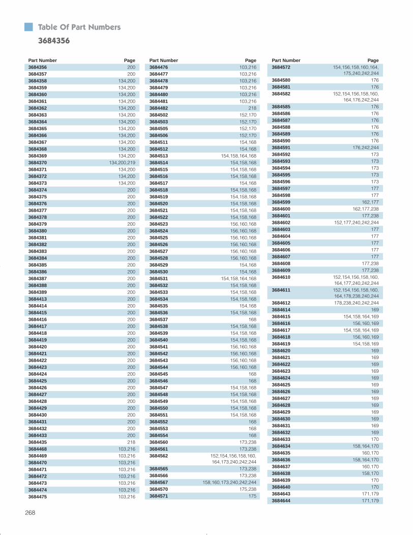
Part Number Page3684356 2003684357 2003684358 134,2003684359 134,2003684360 134,2003684361 134,2003684362 134,2003684363 134,2003684364 134,2003684365 134,2003684366 134,2003684367 134,2003684368 134,2003684369 134,2003684370 134,200,2193684371 134,2003684372 134,2003684373 134,2003684374 2003684375 2003684376 2003684377 2003684378 2003684379 2003684380 2003684381 2003684382 2003684383 2003684384 2003684385 2003684386 2003684387 2003684388 2003684389 2003684413 2003684414 2003684415 2003684416 2003684417 2003684418 2003684419 2003684420 2003684421 2003684422 2003684423 2003684424 2003684425 2003684426 2003684427 2003684428 2003684429 2003684430 2003684431 2003684432 2003684433 2003684435 2183684468 103,2163684469 103,2163684470 103,2163684471 103,2163684472 103,2163684473 103,2163684474 103,2163684475 103,216
Table Of Part Numbers
3684356
268
Part Number Page3684476 103,2163684477 103,2163684478 103,2163684479 103,2163684480 103,2163684481 103,2163684482 2183684502 152,1703684503 152,1703684505 152,1703684506 152,1703684511 154,1683684512 154,1683684513 154,158,164,1683684514 154,158,1683684515 154,158,1683684516 154,158,1683684517 154,1683684518 154,158,1683684519 154,158,1683684520 154,158,1683684521 154,158,1683684522 154,158,1683684523 156,160,1683684524 156,160,1683684525 156,160,1683684526 156,160,1683684527 156,160,1683684528 156,160,1683684529 154,1683684530 154,1683684531 154,158,164,1683684532 154,158,1683684533 154,158,1683684534 154,158,1683684535 154,1683684536 154,158,1683684537 1683684538 154,158,1683684539 154,158,1683684540 154,158,1683684541 156,160,1683684542 156,160,1683684543 156,160,1683684544 156,160,1683684545 1683684546 1683684547 154,158,1683684548 154,158,1683684549 154,158,1683684550 154,158,1683684551 154,158,1683684552 1683684553 1683684554 1683684560 173,2383684561 173,2383684562 152,154,156,158,160,
164,173,240,242,2443684565 173,2383684566 173,2383684567 158,160,173,240,242,2443684570 175,2383684571 175
Part Number Page3684572 154,156,158,160,164,
175,240,242,2443684580 1763684581 1763684582 152,154,156,158,160,
164,176,242,2443684585 1763684586 1763684587 1763684588 1763684589 1763684590 1763684591 176,242,2443684592 1733684593 1733684594 1733684595 1733684596 1733684597 1773684598 1773684599 162,1773684600 162,177,2383684601 177,2383684602 152,177,240,242,2443684603 1773684604 1773684605 1773684606 1773684607 1773684608 177,2383684609 177,2383684610 152,154,156,158,160,
164,177,240,242,2443684611 152,154,156,158,160,
164,178,238,240,2443684612 178,238,240,242,2443684614 1693684615 154,158,164,1693684616 156,160,1693684617 154,158,164,1693684618 156,160,1693684619 154,158,1693684620 1693684621 1693684622 1693684623 1693684624 1693684625 1693684626 1693684627 1693684628 1693684629 1693684630 1693684631 1693684632 1693684633 1703684634 158,164,1703684635 160,1703684636 158,164,1703684637 160,1703684638 158,1703684639 1703684640 1703684643 171,1793684644 171,179
Section 6_258-Index 4/7/04 9:08 AM Page 11

Table Of Part Numbers 3684093
269
Part Number Page3684645 171,1793684654 1823684655 1823684656 1823684657 1823684658 1823684659 1823684660 1823684661 1823684662 1823684663 1823684664 1823684665 1823684666 1823684668 1823684669 56,57,1833684670 1843684673 1843684674 1843684675 1843684676 1843684677 1843684678 1813684679 1813684680 188,1893684681 188,1893684683 1883684684 1883684685 1883684686 1883684687 1883684688 1883684689 1883684691 1883684692 1883684693 1883684694 1883684695 164,1883684696 1883684698 1883684700 1883684701 1883684702 1883684703 1883684714 1893684715 1893684716 1893684717 1893684718 1893684719 1893684720 1893684721 1893684722 1893684723 1893684724 1893684725 1893684726 1903684727 1903684728 1903684729 1903684730 1903684731 1903684732 1903684733 190
Part Number Page3684734 1903684735 1903684736 1903684737 1903684738 180,2083684739 2083684740 2083684741 2083684742 2083684743 2083684744 2083684745 2083684746 2083684747 2083684748 2083684749 2083684750 2083684751 2083684752 2083684753 2083684754 2083684807 158,160,164,238,240,2423684808 177,1783684812 1963684813 1963684814 1963684839 1963684840 1963684841 1963684842 1963684843 1963684844 1963684845 1963684870 1953684871 1953684872 1953684881 152,154,156,158,160,164,2183684882 2193684883 164,218,2193684884 158,160,164,218,2193684885 2083684886 2083684887 2083684888 2083684889 2083684890 2083684891 56,2083684892 2083684893 2083684894 2083684895 56,2083684896 2083684897 56,2083684898 2083684899 2083684900 2083684901 2083684902 2083684903 2083684904 2083684905 2083684906 2083684907 2083684908 208
Part Number Page3684909 2083684910 2083684911 2083684912 2083684913 56,2083684914 2083684915 2083684916 2083684917 56,2083684918 2083684919 56,2083684920 2083684921 2083684922 2083684923 2083684924 2083684925 2083684926 2083684927 2083684928 2083684929 2083684930 2083684954 1833684955 1733684956 1733684957 188,1893684958 1883684960 1733684961 1733684962 1753684963 1763684964 1763684965 1773684966 1773684974 177,1783684976 2083684977 2083685037 1803685038 1803685039 1803685040 1803685041 1803685058 1803685059 1803685060 1803685061 1803685062 1803685077 2163685078 2163685079 2163685080 2163685081 2163685082 2163685083 2163685084 2163685085 2163685086 2163685087 2163685088 2163685089 2163685090 2163685091 2163685092 2163685093 216
Section 6_258-Index 4/7/04 9:08 AM Page 12

Part Number Page3685094 2163685095 2163685096 2163685097 196,197,2193685137 1803685138 1803685139 1803685140 1803685141 1803685158 1803685159 1803685160 1803685161 1803685162 1803685176 1803685177 2093685178 26,28,30,32,56,110,112,2093685179 2093685180 2093685181 2093685182 26,28,30,32,56,110,112,2093685183 2093685184 28,32,56,112,2093685185 2093685186 26,28,30,32,56,110,112,2093685187 2093685188 2093685189 2093685190 26,28,30,32,56,110,112,2093685191 2093685192 28,32,56,112,2093685193 2093685194 2093685195 2093685196 2093685197 2193685198 100,102,136,2053685229 177,1783685231 1543685232 1543685233 1543685234 1543685235 1563685236 1563685237 1563685238 1543685239 1543685240 1543685241 1583685242 1583685243 1583685244 1583685245 188,1893685246 1883685247 1883685248 1883685249 1883685250 188,1893685251 1883685252 1883685253 1883685254 1883685256 2193685257 183
Table Of Part Numbers
3685094
270
Part Number Page3685258 1833685259 1833685260 1843685261 1843685262 1843685263 1843685264 1843685267 1733685268 175,1803685269 1733685270 1763685271 1773685272 1763685273 1783685274 1783685275 1783685276 1703685277 1703685281 1543685282 100,205,2193685289 217,2193685290 2193685291 1813685292 1813685294 2153685302 1953685303 1953685319 133,2193685348 28,30,32,1123685349 28,323685350 2083685373 56,2093685411 99,2043685429 2083685453 56,2093685490 2073685491 2073685492 207,214,2153685493 207,214,2153685494 207,2143685495 2073685496 2073685497 2073685498 2073685499 2073685500 135,2023685501 2023685502 2023685503 2023685504 135,2023685505 2023685506 135,2023685508 135,2023685509 2023685510 2023685511 2023685512 135,2023685513 2023685514 135,2023685516 135,2023685517 2023685518 2023685519 2023685520 135,202
Part Number Page3685521 2023685522 135,2023685524 101,135,2023685525 2023685526 2023685527 2023685528 101,135,143,2023685529 2023685530 101,135,2023685532 101,135,2023685533 2023685534 2023685535 2023685536 101,135,2023685537 2023685538 101,135,2023685540 101,135,2023685541 2023685542 2023685543 2023685544 101,135,2023685545 2023685546 101,135,2023685569 2063685570 2063685571 2063685572 2063685573 2063685574 2063685575 2063685576 2063685577 2063685578 2063685579 2063685580 2063685581 2063685582 2063685583 2063685584 2063685585 2063685586 2063685589 132,2033685590 132,2033685595 2073685596 2073685597 2073685598 2073685599 207,2153685600 207,214,2153685601 207,214,2153685602 207,214,2153685603 207,214,2153685604 2073685605 2073685606 2073685607 2073685608 2073685609 2073685610 2073685611 2073685612 2073685613 2073685614 2073685615 207
Section 6_258-Index 4/7/04 9:08 AM Page 13

Table Of Part Numbers 3686192
271
Part Number Page3685616 2073685617 2073685618 2073685619 102,1363685625 2193685626 123,132,2013685627 123,132,2013685628 2153685629 214,2153685630 214,2153685631 214,2153685632 2153685633 214,2153685634 214,2153685635 214,2153685636 2143685637 2143685638 2143685639 2143685640 2143685641 2143685642 1883685645 214,2153685646 214,2153685648 214,2153685649 214,2153685650 2153685651 2153685652 2153685653 2153685654 2153685655 2153685656 2153685657 2153685658 2153685659 2153685660 2153685661 2153685662 2153685663 2153685664 2153685665 2153685666 2153685667 2153685668 2153685669 2153685670 2153685671 2153685672 2153685673 2153685674 2153685675 2153685676 2153685677 2153685678 2153685679 2153685680 2153685681 2153685683 214,2173685684 214,2173685685 214,2173685686 214,2173685687 214,2173685688 214,217
Part Number Page3685689 214,2173685690 214,2173685691 214,2173685692 214,2173685693 214,2173685694 214,2173685695 214,2173685696 214,2173685697 214,2173685698 214,2173685699 214,2173685700 214,2173685701 214,2173685702 214,2173685703 214,2173685704 214,2173685705 214,2173685706 214,2173685708 2143685709 2143685710 2143685711 2143685712 2143685715 2153685716 2153685743 156,160,1683685744 156,160,1683685745 156,160,1683685746 2073685747 2073685748 2073685749 2073685750 207,2153685751 207,214,2153685752 207,214,2153685753 207,214,2153685754 207,214,2153685755 2143685756 2143685757 2143685758 2073685759 1823685760 218,2193685761 2143685762 2143685763 2143685764 2153685765 2153685767 214,2153685769 214,2153685772 2153685773 2153685776 2153685777 2153685783 1813685784 1813685785 1813685786 1813685787 1813685788 1813685789 177,1783685790 1843685793 1683685794 156,168
Part Number Page3685795 156,1683685796 156,160,1683685797 1683685798 1683685799 1683685808 2193685809 2193685813 188,1893685814 188,1893685825 2183685826 2183685827 218,2193685828 2183685829 2193685830 2183685831 2183685832 218,2193685833 2183685834 2183685835 2183685836 2183685837 218,2193685838 2183685850 156,1683685851 188,1893685852 1883685853 1883685855 188,1893685856 1893685857 1893685890 1683685891 156,1683685892 156,160,1683685893 1683685894 156,1683685895 156,160,1683685896 1683685897 156,1683685898 1683685899 1683685953 2193685954 2193685955 218,2193685959 1683685969 2193685985 1733685991 1753686001 2193686002 2193686005 1763686015 2193686035 2183686063 56,57,1833686135 1423686136 183,1843686137 1843686138 2093686139 2093686140 2093686146 123,132,2013686149 1773686159 154,156,164,1763686191 1763686192 169
Section 6_258-Index 4/7/04 9:08 AM Page 14

Part Number Page3686923 2193686924 2193686935 2193686973 100,171,179,205,2403686974 100,171,179,205,238,2403686975 100,158,164,171,179,
205,214,238,2403686976 100,171,179,205,2423686977 100,158,164,171,179,
205,214,2423686978 100,171,179,2053686979 100,158,171,179,2053686980 100,171,179,2053686981 100,171,179,2053686982 171,1793686989 2163687014 1873687015 169,2193687020 217,2193687021 218,2193687050 202,206,209,2193687051 202,2193687052 1873687098 1043687146 207,2193687471 1043687498 46,543687507 2143687519 207,215,218,2193687520 2143687521 2143687522 2143687523 2143687524 2143687525 2143687526 1823687527 1823687528 1823687536 2143687555 214,2173687556 214,2173687557 214,2173687558 214,2173687559 214,2173687560 214,2173687561 214,2173687562 214,2173687563 214,2173687564 214,2173687565 214,2173687566 214,2173687567 214,2173687568 214,2173687574 1773687575 1773687576 1773687577 1773687582 2183687583 2183687584 2183687585 214,2173687587 2143687588 2143687589 2153687590 215
Table Of Part Numbers
3686193
272
Part Number Page3686193 1693686194 1693686195 1713686196 1713686197 1713686329 2273686338 1223686359 2273686397 783686398 943686414 34,783686473 1273686474 1273686475 1303686476 1303686477 1303686478 1303686479 1303686480 1303686481 1303686482 1303686483 1303686484 1303686485 1303686486 1303686487 1303686488 1303686489 1303686490 1303686491 1303686492 1303686493 1303686494 1303686495 1303686496 1303686497 1303686498 1303686499 1303686500 1303686501 1303686502 1303686503 1303686504 1303686505 1303686506 1303686507 1303686508 1303686509 1303686510 1303686511 1303686512 1303686513 1303686514 1303686536 99,2043686537 993686541 993686546 72,83,84,88,903686547 723686548 723686549 34,83,84,913686552 733686555 1313686556 1313686557 131
Part Number Page3686558 1313686559 1313686560 1313686561 1313686562 1313686563 1313686564 1313686565 1313686566 1313686567 1313686568 1313686569 1313686570 72,73,87,88,90,913686571 72,73,833686572 104,2013686573 104,2013686574 104,2013686575 723686576 723686578 723686579 733686581 733686585 1313686586 1313686587 1313686588 1313686589 1313686590 1313686591 1313686592 1313686593 1313686594 1313686595 1313686596 1313686597 1313686598 1313686599 1313686634 1273686635 1273686643 2263686644 2263686645 2263686646 2263686647 2263686648 2263686649 2263686650 2263686655 2273686656 2273686657 2273686658 2263686659 2263686679 72,73,903686684 72,733686877 34,66,74,83,913686886 543686887 2233686888 2233686889 2233686914 2193686915 2193686916 2193686917 2193686919 176
Section 6_258-Index 4/7/04 9:08 AM Page 15

Table Of Part Numbers 3688342
273
Part Number Page3687591 2153687602 154,156,1643687608 1273687609 1273687610 1273687611 1273687612 2263687613 2263687614 2263687615 2263687618 1883687619 1883687620 1883687621 1883687623 1883687624 162,1913687625 162,1913687626 1883687627 1883687628 1883687629 1883687630 1893687631 1893687633 1893687634 1893687635 1893687636 1893687637 1893687638 1893687639 1893687640 1913687641 1913687642 1913687643 1913687644 1913687645 1913687646 1913687647 1913687648 1913687649 1913687650 1913687651 1913687652 1913687655 2063687656 2063687657 2063687658 2063687659 2063687660 2063687661 2063687662 2063687663 2063687664 2063687667 1623687668 1623687669 1623687670 1623687671 1623687672 1623687673 1623687674 1623687677 162,1913687680 1623687681 162
Part Number Page3687682 1623687683 1623687684 1623687685 1623687686 1623687687 1623687688 1623687689 1623687690 1623687691 1623687692 162,1913687693 2073687696 1143687698 1143687699 1143687700 1143687702 1163687703 1163687704 1163687705 1183687706 1183687708 1203687709 1233687710 1233687711 1223687712 1223687714 1223687716 1223687724 1743687726 1823687780 1643687781 1643687782 1643687783 1643687784 1643687785 1643687802 443687803 383687804 383687812 403687814 2343687815 2343687816 2343687817 2343687818 2343687819 2343687820 2343687821 2343687822 2343687823 2343687826 543687829 563687830 563687832 57,142,183,1843687833 563687834 563687835 563687838 101,1353687839 101,1353687846 101,1353687848 1353687849 1353687856 1353687859 72
Part Number Page3687860 723687861 723687862 723687863 723687864 723687865 723687866 733687867 733687868 733687869 733687870 733687871 733687873 66,743687874 66,743687875 66,743687876 663687877 663687878 663687879 663687880 863687881 903687924 56,185,1953687932 104,2013687933 104,2013687934 104,2013687936 57,58,1833687937 57,58,1833687951 57,58,1833687955 104,123,132,2013687956 56,100,186,2053687973 903687987 543687988 543687992 89,913688000 1733688001 1733688002 1753688003 1763688004 1763688024 1743688037 903688055 56,57,1833688063 2233688088 593688104 152,1753688105 152,1913688106 152,1913688107 152,1913688108 152,1913688109 152,1913688160 2063688266 20,213688267 20,213688268 20,213688290 203688297 2253688299 203688307 203688317 203688320 193688322 193688323 193688324 193688342 21
Section 6_258-Index 4/7/04 9:08 AM Page 16

Table Of Part Numbers
3688378
274
Part Number Page3688378 193688386 213688388 193688397 213688404 933688405 933688406 74,753688407 743688409 77,793688410 953688411 953688412 943688413 943688419 723688420 723688422 753688423 753688424 753688425 753688426 753688427 753688429 203688451 1103688452 1103688453 1123688454 1123688501 733688504 743688505 743688507 66,743688508 66,753688527 1433688601 72,73,913688602 893688603 883688606 100,171,179,2053688607 893688608 903688609 100,171,179,2053688610 100,171,179,2053688611 100,171,179,2053688612 100,171,179,2053688613 100,171,179,2053688614 100,171,179,2053688615 100,171,179,2053688616 100,171,179,2053688623 663688633 100,171,179,2053688634 100,171,179,2053688658 137,2113688659 137,2113688660 137,2113688661 137,2113688662 137,2113688663 137,2113688664 137,2113688665 137,2113688697 26,28,30,323688704 1743688760 203688763 203688770 98,133,2033688771 98,133,2033688772 98,133,203
Part Number Page3688773 98,133,2033688780 98,133,2033688781 98,133,2033688784 98,133,2033688785 98,133,2033688786 99,2043688787 99,2043688790 99,2043688791 99,2043688924 753688925 753688927 753689036 1833689044 2343689045 2343689046 2343689047 2343689048 2343689089 1833689090 183,1843689092 183,1843689093 1833689097 1833689098 1833689177 263689178 263689179 283689180 283689181 303689182 303689183 323689184 323689188 783689190 783689191 783689193 763689194 763689195 34,763689196 76,783689197 763689198 763689205 733689206 733689209 733689210 843746000 252,2613747000 252,2613748000 252,2613749000 252,2613750000 2543750002 2543750004 2543750030 2543750032 2543750034 2543750100 2523750102 2523750104 2523750110 2523750112 2523750114 2523750200 2523750202 2523750204 252
Part Number Page3750210 2523750212 2523750214 2523750220 2523750222 2523750224 2523750300 2523750302 2523750304 2523750310 2543750312 2543750313 2543750320 2543750322 2543750324 2543750330 2543750332 2543750334 2543750340 2543750342 2543750344 2543750350 2523750352 2523750354 2523750360 2523750362 2523750364 2523750400 2523750402 2523750404 2523750410 2543750412 2543750414 2543750420 2543750422 2543750424 2543750430 2543750432 2543750434 2543750440 2543750442 2543750444 2543750450 2523750452 2523750454 2523750600 2543750602 2543750604 2543750610 2543750612 2543750614 2543750620 2543750622 2543750624 2543750630 2543750632 2543750634 2543750640 2543750642 2543750644 2543750650 2543750652 2543750654 2543750700 254
Section 6_258-Index 4/7/04 9:08 AM Page 17

Table Of Part Numbers 9808038
275
Part Number Page3750702 2543750704 2543750710 2543750712 2543750714 2543750720 2543750722 2543750724 2543750730 2543750732 2543750734 2543750900 2543750902 2543750904 2543750910 2543750912 2543750914 2543750920 2543750922 2543750924 2543750930 2543750932 2543750934 2543751100 254,2603751110 2603751120 254,2603751130 254,2603751150 254,2603751160 254,2603751170 254,2603751180 254,2603751200 252,2583751202 252,2583751204 252,2583751210 254,2583751212 254,2583751214 254,2583751250 252,254,2583751260 252,254,2583751270 252,254,2583751300 252,2593751310 2593751320 254,2593751330 254,2593751340 254,2593751350 254,2593751360 2593751370 2593751380 2593751390 2593751410 2563751420 2563751430 2593751450 2573751460 2573751500 252,254,2563751510 252,254,2563751520 252,254,2563751530 254,2603751540 254,2603751600 254,2603751610 254,2603751620 254,2603751630 254,260
Part Number Page3751640 254,2563751650 252,2563751660 252,2563751670 252,254,2563751680 252,254,2563751690 254,2563751700 252,2563751710 252,2563751720 252,254,2563751730 252,254,2563751740 254,2563751750 254,2563751760 254,2563751770 254,2563751780 254,2563751790 254,2563751800 2583751810 2583751820 254,2573751830 254,2573751850 2593751852 2593751854 2593751900 252,254,2573751910 252,254,2573751920 254,2573751930 254,2573798000 2563900000 2473901000 238,240,242,244,2473919000 2463981000 2383981001 2403981002 2403981003 2403981010 2403981020 2383981030 2403981040 2383981050 2383981060 2403981070 2383981080 2383981090 2403981100 2403981110 2423981120 2423981130 2423981140 2423981150 2423981160 2423981170 2443981175 2443981180 2443981185 2443981190 2443981195 2443981200 238,240,2463981210 238,240,2463981220 242,2463981230 240,242,2463981240 244,2463981250 244,2463981260 238,240,246
Part Number Page3981270 242,2463981280 240,242,2463981290 244,2463981300 238,240,2463981310 238,240,246,2473981320 242,2463981330 242,2463981340 244,2463981350 238,240,242,2473981360 238,240,242,244,2473981370 240,242,244,2473981380 242,244,2473981390 2473981400 2473981410 2473981420 238,2473981430 238,2473981440 240,2473981450 242,2473981460 242,2473981470 244,2473981480 2473981500 2473981510 2473981560 244,2463981570 240,2463981580 240,2463981590 244,2463981700 240,2423981710 240,242,2443981720 240,242,2443981730 242,2443981740 240,2423981750 240,242,2443981760 240,242,2443981770 242,2443981900 240,2423981910 240,242,2443981920 240,242,2443981930 242,2443981940 240,2423981950 240,242,2443981960 240,242,2443981970 242,2447980000 2607980110 2609805073 110,1129805160 219805161 219805172 219805174 219805404 749805701 26,28,110,112,1429805702 30,32,1429805703 26,28,1429805704 30,32,1429805705 26,28,110,112,1429805706 30,32,1429807081 349807637 429807773 529808028 529808029 369808038 52
Section 6_258-Index 4/7/04 9:08 AM Page 18

Table Of Part Numbers
9910016
276
Part Number Page9808039 529808466 369808544 509808550 489808623 179808691 219808692 219808693 219808764 219810117 2239810337 879810338 879810390 919810436 1439810437 1439810438 1439810439 1439810637 84,859810933 939810965 1449810966 1449810967 1449812625 859817942 739818073 899818080 759818128 1449901398 2189901417 182,2189901991 1529902188 152,1919904928 1279904929 1279904930 1279904931 1279904932 1279904933 1279905992 101,1349905993 101,1349905994 101,1349905995 101,1349910007 1279910008 1279910009 1279910010 1279910011 1279910012 1279910013 1279910014 1279910015 1279910016 127
Section 6_258-Index 4/7/04 9:08 AM Page 19

Table Of Model Numbers
277
Model Number PagePS1400B 65,70,73PS1401 73PS1405 70,71,73PS1406 71PS1420 71PS1420B 73PS1421 73PS1430 71PS1430B 73PS1431 73PS1440 71,73PS1441 73PS1450 71,73PS1451 73PS1455 73PS1460 71PS1460B 73PS1461 71,73PS1462 73PS1600 72,73,88,90,91PS23180 80PS23400 80PS23500 80PS23600 80PS23700 80PS23800 80PS3300 87,88,90,91PS3310 26,28,110,112,142PS3311 30,32,142PS3312 26,28,110,112,142PS3313 30,32,110,142PS3314 26,28,112,142PS3315 30,32,142PS3350 87,143PS3351 143PS3352 143PS3353 143PS3357 79,143PS3358 143PS3380 87,92PS3395 93PS3396 93PS3397 93PS3400 87PS3900 54PS3901 54PS3902 54,55PS3903 54PS3904 54PS4400 65,66,70,74,75,78,83,91PS4400B 65,70,71,75PS4401 66PS4402 74PS4402B 75PS4407B 71,75PS4408 74PS4420 66,74PS4420B 71,75PS4421 66PS4422 74PS4422B 75PS4430 66,74PS4430B 71,75PS4431 66
Model Number PagePS4432 74PS4432B 71,75PS4440 66,74PS4440B 71,75PS4441 66PS4442B 75PS4450 66,74PS4450B 71,75PS4452B 75PS4460 66,74PS4460B 71,75PS4462 66PS4462B 75PS4800 76PS4805 76PS4808 76PS4810 76PS4818 76PS4820 76PS4821 76PS4822 76PS4900 78,79PS4905 78PS4920 78PS4921 78PS4922 78PS6090 77,79PS6100 54PS6600 95PS6610 95PS6620 95PS6700 94PS6701 94PS6703 94
Model Number Page7010 267020 267030 287040 287510 1107520 1107530 1127540 11210401 2011401 2011404 2011601 2011604 201600-12 871600-16 871600-20 877010-DC 307020-DC 307030-DC 327040-DC 3287A10013-A01 26,28,30PS1100 64PS1101 64PS1111 65,82PS1112 65,82PS1121 65,82PS1122 65,82PS1130 65,70,72,73,83PS1131 65,84PS1132 65,75,85PS1133 65,75,84PS1134 65,85PS1150 70,75,86PS1160 76PS1222 88PS1227 88PS1240 90PS1241 72,73,90PS1245 90PS1247 90PS1248 90PS1250 72,73PS1250A 89PS1255 89,91PS1257 89PS1258 89PS1260 72,73,91PS1300 65,70,71,72,83,84,88,90PS1301 72PS1315B 72PS1320 71,72PS1321 72PS1322B 72PS1330 71,72PS1331 72PS1340 71,72PS1341 72PS1350 71,72PS1351 72PS1360 71,72PS1361 71,72PS1362 72PS1400 65,70,71,73,83,84,91PS1400A 73
Section 6_258-Index 4/7/04 9:08 AM Page 20