fuel supply system - industrial … turbine power plant fuel supply system ct-gt04-24a-sd revision 0...
TRANSCRIPT
FUEL SUPPLY SYSTEM
TRAINING SYSTEM DESCRIPTION (GT-GT04-24A-SD)
Combustion Turbine Plant
March 11, 2003

Combustion Turbine Power Plant Fuel Supply System
CT-GT04-24A-SD
Revision 0 – March 11, 2003 Page 1
PREFACE
This System Description has been designed to assist you in meeting the requirements of Module
(CT-GT04) of the Plant Operator Training Program. It contains information about the
Combustion Turbine Fuel Supply System associated with the GT24A Combustion Turbine. This
includes system purpose, flow path, and details about major system components and operation.
The Operator(s) is/are responsible for learning the information contained in this document. The
Operator(s) is/are also responsible for obtaining any required certifications and making proper
inspections, logging/recording, reporting, minimizing wastewater and excessive emissions.
A separate document, System Operating Procedure (CT-GT04-24A-SOP), covers detailed
operation of the Combustion Turbine GT24A Fuel Supply System.
Employees need to be aware of environmental impacts involved with this system. Improper
operation of this system could cause contamination, excess wastewater and excessive emissions.
Any leak and/or spill that discharges to the floor drains or to State waters must be reported
immediately as outlined in the Spill and Counter Measure Plan.

Combustion Turbine Power Plant Fuel Supply System
CT-GT04-24A-SD
Revision 0 – March 11, 2003 Page 2
FUEL SUPPLY SYSTEM DESCRIPTION
TABLE OF CONTENTS
1.0 Introduction ....................................................................................................................... 4
1.1 Purpose .............................................................................................................................. 4
1.2 Basic System Description .................................................................................................. 4
1.2.1 System Parameters ............................................................................................................ 5
1.3 System Flowpaths .............................................................................................................. 5
2.0 System Major Components ............................................................................................... 8
2.1 Fuel Gas System and Burner Supply Systems .................................................................. 9
2.1.1 Fuel Gas Supply ................................................................................................................ 9
2.1.1 Fuel Gas Building Equipment ......................................................................................... 10
2.1.2 Fuel Gas Control Block ................................................................................................... 11
2.1.2.1 EV Combustor Fuel Gas Supply to Burners ................................................................... 11
2.1.2.2 EV Combustor Fuel Gas Supply to Burners Controls ..................................................... 13
2.1.2.3 SEV Combustor Fuel Gas Supply to Burners ................................................................. 14
2.1.2.4 SEV Combustor Fuel Gas Control .................................................................................. 14
2.2 Fuel Oil System ............................................................................................................... 15
2.2.1 Fuel Oil Block ................................................................................................................. 16
2.2.2 Fuel Oil Control Block .................................................................................................... 19
3.0 System Operation ............................................................................................................ 22
3.1 System Startup ................................................................................................................. 22
3.2 Normal Operation ............................................................................................................ 25
3.3 System Shutdown ............................................................................................................ 27
4.0 References ....................................................................................................................... 29

Combustion Turbine Power Plant Fuel Supply System
CT-GT04-24A-SD
Revision 0 – March 11, 2003 Page 3
List of Figures:
Figure 1 – Fuel Gas Twin Filter Arrangement
Figure 2 – Fuel Gas Control Block
Figure 3 – Fuel Oil Control Block
Figure 4 - Fuel Oil Sump
Figure 5 – Fuel Oil Pump
Figure 6 – Fuel Oil Control Block
List of Drawings
Drawing 1 – Fuel Gas System Simplified Diagram
Drawing 2 – Fuel Oil Building Simplified Diagram
Drawing 3 – Fuel Oil Supply Simplified Diagram

Combustion Turbine Power Plant Fuel Supply System
CT-GT04-24A-SD
Revision 0 – March 11, 2003 Page 4
1.0 Introduction
Chapter Objectives:
Describe the purpose of the Fuel Supply System.
1. State, from memory, the purpose of the Fuel Supply System.
2. Draw a simplified Fuel Supply System diagram. Describe the flow path through
the device and how the Fuel Supply System performs its functions.
3. State, from memory, the names and purpose of the major Fuel Supply System
components.
4. List the normal Fuel Supply System operating parameters.
1.1 Purpose
The purpose of the Unit 6 or Unit 7 GT24A Style Fuel Supply System is to supply and control
the pressure and volume of Fuel, (Fuel Gas or No. 2 Diesel) sent to the Combustion Turbine EV
and SEV Combustors.
1.2 Basic System Description
(Refer to Drawing 1 when reading this section
The Fuel Supply System is made up of the Fuel Gas System and the Fuel Oil System.
Fuel Gas is supplied from Texas Eastern and Tennessee Supply lines to the Plant Site.
The Fuel Gas, as it pertains to the GT24A Combustion Turbine, functions as the primary fuel
source for firing the EV and SEV combustors. Additionally the Fuel Gas acts as the fuel supply
to the ignitors and pilot as well.
No. 2 Diesel Fuel supplied to the Combustion Turbine Plant location acts as the secondary fuel
source for firing the EV and SEV Combustors.

Combustion Turbine Power Plant Fuel Supply System
CT-GT04-24A-SD
Revision 0 – March 11, 2003 Page 5
1.2.1 System Parameters
Number Of Fuel Oil Tanks Two (2)
Fuel Oil Tank Capacity Each 1.1 million gallons
Fuel Oil Pump discharge pressure 133 Bar
Minimum Fuel Gas Supply Pressure 650 psi
Twin filter DP (Differential At Which
Fuel Oil Filters Are Swapped) . Eight (8) Bar
Pressure Limiting Valve (Located Downstream
Of The Twin Filter Arrangement Set Pressure) 25 Bar
LP Fuel Oil Pressure Limiting Valve Set Pressure 1.7 Bar
Fuel Oil Sump Level Alarms Greater than 400 mm (and)
Less than 250 mm
1.3 System Flowpaths
(Refer to Drawings 1, 2, and 3 while reading this section.)
Fuel Gas Supply
Fuel Gas, supplied from Texas Eastern and Tennessee Supply lines to the Plant Site, routes
through the associated unit’s Fuel Gas Supply line and to its associated twin filter arrangement
(MBP31 AA001). From the in-service filter, the fuel gas is directed to a tee type piping
arrangement routing to the EV and SEV Combustor Main Shutoff valves.
Main Shutoff Valve MBP31 AA001 routes fuel gas toward the EV Combustor. A header vent
valve take-off, located downstream of the main shutoff valve, is used to evacuate the fuel gas
supply header between the shutoff valve and the EV Combustor Trip/Shutoff Valve (MBP41
AA001). A dirt trap (MBP31 AT001) is located downstream of the main shutoff valve and vent
connection. Fuel Gas within the EV Combustor supply line is directed to trip/shutoff valves for
the EV Combustor Pilot, Ignitor, and to line supplying the EV Combustor. Each line is equipped
with a Trip Shutoff Valve, a throttling valve and a vent valve located between the associated
trip/shutoff valve and throttling valve arrangement. The relief/vent arrangement for each line

Combustion Turbine Power Plant Fuel Supply System
CT-GT04-24A-SD
Revision 0 – March 11, 2003 Page 6
allows gas trapped between the closed Trip and Throttling valves to vent to a location above the
building roof.
Main Shutoff Valve MBP31 AA001 also routes fuel gas to the SEV Combustor. Fuel Gas within
the SEV Combustor supply line is directed to a trip/shutoff valve for the SEV Combustor. This
line is equipped with a Trip Shutoff Valve, a throttling valve and a vent valve located between
the trip/shutoff valve and throttling valve arrangement. A relief/vent arrangement is provided to
allow gas trapped between the closed Trip and Throttling valve to vent to the header it shares
with the EV vent allowing vented gas to flow to a location above the building roof.
Fuel Oil Supply
The Fuel Oil Supply system is the secondary method of firing of the EV and SEV Combustors.
Fuel Oil Supply (located within the Fuel Oil Building, is routed through the Main Fuel Shutoff
Valve (MBN31 AA001). When OPEN, fuel oil passes on to the header supplying the twin filter
arrangement (MBN31 AT001). A low pressure limiting valve (MBN31 DP001) functions to
route excess supply pressure to the Fuel Oil Sump. A fuel oil sump pump (MBN35 AP001)
directs the flow of oil collected within the Fuel Oil Sump to the Fuel Oil Return. A centrifugal
type vent arrangement within the sump allows for vapors within the sump to be vented to
atmosphere, via a connection routing vapors to a location outside of the building.
Fuel oil passing through the in-service Twin-Filter, via ganged three way valves, routes to the
Fuel Oil Pump (MBN31 AP001). The Fuel Oil Pump discharges through a minimum flow valve
(or orifice arrangement) to the Fuel Oil System from fuel pump. The Fuel Oil Pump minimum
flow valve (MBN32 AA001) ensures minimum flow through the fuel oil pump, reducing the
potential for pump cavitation. Fuel oil flowing through the minimum flow valve routes through
a normally open gate type isolation valve and combines with the Sump Pump (MBN35 AP001)
discharge, routing to the fuel oil return piping. The fuel oil building is equipped with a heating
and ventilation system (MBN36 AN001) routing vapors trapped within the building to
atmosphere (outside the confines of the building).

Combustion Turbine Power Plant Fuel Supply System
CT-GT04-24A-SD
Revision 0 – March 11, 2003 Page 7
The Fuel Oil Supply Header routes No. 2 Diesel, pressurized by the pump, to the EV Combustor
Trip Shutoff Valve (MBN40 AA001) and to its flow control valve (MBN41 AA001). A Fuel Oil
Drain Valve (MBN50 AA001) tees from the piping downstream of the trip valve. A Shutoff
valve (MBN42 AA010), also located downstream of the EV Combustor trip valve acts to isolate
flow to the SEV Combustor. Flow to the SEV Combustor is controlled control valve
(MBNAA001). This line is also equipped with a drain valve (MBN52 AA001). Each drain
valve, when OPEN, routes flow to the fuel oil sump.

Combustion Turbine Power Plant Fuel Supply System
CT-GT04-24A-SD
Revision 0 – March 11, 2003 Page 8
2.0 System Major Components
Chapter Objectives:
Describe how the Fuel Supply System Components perform their functions, and how
they interface with other System components.
1. Draw from memory a diagram of the Fuel Supply System showing major
components.
2. State, from memory, the names and purposes of major Fuel Supply System
components.
3. Describe the construction of and flow paths through the major components.
The GT24A Fuel Supply System (as found on Units 6 and 7) consists of the following major
components:
1. Fuel Gas System
Fuel Gas Supply
Fuel Gas Building Equipment
Fuel Gas Control Block
EV Combustor Fuel Gas Supply to Burners
SEV Combustor Fuel Gas Supply to Burners
2. Fuel Oil Supply System
Fuel Oil Block
Fuel Oil Control Block
Combustion Turbine Power Plant Fuel Supply System
CT-GT04-24A-SD
Revision 0 – March 11, 2003 Page 9
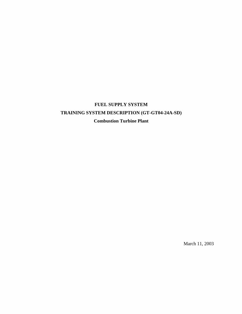
Figure 1 – Fuel Gas Twin Filter Arrangement
2.1 Fuel Gas System and Burner Supply Systems
(Refer to Drawing 1 when reading this section.)
The Fuel Gas System delivers the fuel gas supplied by the gas supply system to the EV and SEV
burners at a flow rate corresponding to the power output demanded of the gas turboset and in the
condition required for operation.
2.1.1 Fuel Gas Supply
Fuel Gas for the Units 6 and 7 Combustion Turbines is supplied from Texas Eastern and
Tennessee Supply lines to the Plant Site. Fuel gas supply pressure is 650 psig. The fuel gas is
routed to the unit via a 10-inch line. The fuel gas is filtered via twin filter arrangement (MBP01
AT001). The twin filters, one filter normally in service, allows for the removal of entrained

Combustion Turbine Power Plant Fuel Supply System
CT-GT04-24A-SD
Revision 0 – March 11, 2003 Page 10
debris and moisture from the fuel gas supply. The Twin Filter Arrangement is illustrated on
Figure 1. The inlet and outlet valves of the twin filter arrangement are ganged together,
allowing flow to the filters to be swapped in a single action. Each filter is equipped with a vent
and drain valve arrangement. Differential pressure is measured across each filter and is indicated
locally. Increased differential pressure is indicative of filter cleanliness, indicating the need to
swap to the alternate filter. A differential pressure alarm for each filter is also is provided.
A gas flow integrator is located downstream of the twin filter arrangement. The flow integrator
is used to measure the amount of fuel gas flow to the Unit Turboset. From the integrator, the
fuel gas continues flowing through a 10-inch line and to a dual 6-inch outlet tee routing to the
Fuel Gas Building.
2.1.1 Fuel Gas Building Equipment
The 6-inch lines direct the flow of fuel gas to the EV and SEV Combustor Fuel Gas Main and
Shutoff valves. The Fuel Gas Main Shutoff Valves are motor operated valves with manual
drives, used to completely isolate the flow of fuel gas flowing through the associated 6-inch
supply line. Each Fuel Gas Main Shutoff Valve (MBP31 AA001 to the EV Combustor and
MBP32 AA001 to the SEV Combustor) is actuated by an electric motor. Each motor is equipped
with a motor heater. The motor heaters function to prevent condensation from occurring within
the motor, since this leads to premature motor failure. Main Shutoff Valve MBP31 AA001,
when OPEN routes fuel gas toward the EV Combustor. A header vent valve take-off, located
downstream of the main shutoff valve, when OPEN vents to atmosphere, any fuel gas from the
fuel gas supply header trapped between the shutoff valve and the EV Combustor Trip/Shutoff
Valve (MBP41 AA001), as well as to gas trapped between the Ignition gas shutoff valve and the
pilot gas shutoff valve. A dirt trap (MBP31 AT001) is located downstream of the main shutoff
valve and vent connection. The dirt trap is used to separate entrained debris from the Fuel Gas.

Combustion Turbine Power Plant Fuel Supply System
CT-GT04-24A-SD
Revision 0 – March 11, 2003 Page 11
Figure 2 – Fuel Gas Control Block
2.1.2 Fuel Gas Control Block
The fuel gas control block is equipped with trip/shutoff valves, control valves, and relief valves
serving the EV and SEV Combustor. Electro hydraulic controlled servomotors control positions
of the control valves and their associated gas flows. Control oil in the hydraulic safety system
(MBX42) and power oil to fuel gas (MBX44) operate the servomotors. The Fuel Gas Control
Block is illustrated on Figure 2.
2.1.2.1 EV Combustor Fuel Gas Supply to Burners
There are three separate fuel gas supplies to the EV Combustor. These are the ignition gas
supply, the EV Pilot supply and the EV Combustor Main Burner (PREMIX) supply. The
equipment is grouped together in the Fuel Gas Control Block.
Ignition Gas
Ignition gas is supplied to the turboset for initial light off of the ignition torches. The ignition
gas supply header takes off downstream of the Fuel Oil Building dirt trap, upstream of the EV
Combustor Trip/Shutoff Valve MPT41 AA001. Ignition gas is routed through the Trip Shut Off

Combustion Turbine Power Plant Fuel Supply System
CT-GT04-24A-SD
Revision 0 – March 11, 2003 Page 12
Valve MBP60 AA010, through throttle valve MBP60 AA020 to the EV Combustor ignition
torches. The ignition torch Trip/Shutoff Valve and Throttle Valve are control air to OPEN and
spring to CLOSE. A relief/vent valve (MBP60 AA030) is provided to vent the ignition header
when the trip and throttle valves are CLOSED. The relief/vent valve is CLOSED by control air
and OPENED by a spring. The relief valve, when OPEN routes fuel gas, trapped between the
Shutoff Valve and the Throttle Valve to atmosphere, at a location above the building roof.
Ignition torch temperature is measured. When the temperature exceeds its differential
temperature requirement in a preset time, an enable signal is issued for continuation of the Gas
turbine starting program.
Pilot Gas
The pilots are lit after the ignition torches and are used to light off the main EV burners. The
pilot gas supply header takes off downstream of the Fuel Oil Building dirt trap, upstream of the
EV Combustor Trip/Shutoff Valve MPT41 AA001. Pilot gas is routed through the Trip Shut Off
Valve MBP43 AA003 through throttle valve MBP43 AA002 to the EV Combustor pilots. The
pilots function to ignite the main EV burners. The pilot gas Trip/Shutoff Valve and Throttle
Valve are hydraulic (via power oil and control oil to the associated servomotor) to OPEN and
spring to CLOSE. A relief/vent valve (MBP53 AA001) is provided to vent the pilot gas header
when the trip and throttle valves are CLOSED. The vent valve is hydraulically CLOSED (via
servomotor) and OPENED by a spring. The relief valve, when OPEN routes fuel gas, trapped
between the Shutoff Valve and the Throttle Valve to atmosphere, at a location above the building
roof.
EV Combustor Burners Supply
The EV Combustor burners are enabled for light off after the pilot ignites and supply the hot
combustion gases required to rotate the HP turbine. The flames of the ignition torches light off
the EV Combustor burners. The EV Combustor Burner fuel gas supply header takes off
downstream of the Fuel Oil Building dirt trap. EV Combustor Burner fuel gas is routed through
the Trip Shut Off Valve MBP41 AA001 and then through throttle valve MBP41 AA002 to the

Combustion Turbine Power Plant Fuel Supply System
CT-GT04-24A-SD
Revision 0 – March 11, 2003 Page 13
EV Combustor burners. The fuel gas Trip/Shutoff Valve and Throttle Valve are hydraulic (via
power oil and control oil to the associated servomotor) to OPEN and spring to CLOSE. A
relief/vent valve (MBP51 AA001) is provided to vent the EV Combustor Main Burner fuel gas
header when the trip and throttle valves are CLOSED. The vent valve is hydraulically CLOSED
(via servomotor) and OPENED by a spring. The relief valve, when OPEN routes fuel gas,
trapped between the Shutoff Valve and the Throttle Valve to atmosphere, at a location above the
building roof.
Temperature downstream of the valve is measured. TIA MBP 41CT002 monitors and transmits
the temperature of the EV Combustor gas supply to the control room. Should the temperature
reach a preset level, an alarm actuates. TP MBP41CT001 locally measures the temperature
within the header. When OPEN it directs the flow of fuel gas to the EV Combustor Gas Flow
Control Valve (MBP41 AA002).
2.1.2.2 EV Combustor Fuel Gas Supply to Burners Controls
When the temperature differential measured at the ignition torches exceeds the requirement in a
preset time frame, the enable signal is given to continue the starting program. The main ignition
sequence is then unblocked. Control valve MBP43 AA002 for EV-Pilot gas opens to the ignition
position (gas flow for main ignition). The gas required for main ignition flows into the EV
combustor through fuel gas control MBP43 and the EV burners, where it ignites by the flame of
the ignition torches (MBM11 AV211 and AV631). When at least two (2) of the three (3)
monitors detect flame within a preset time delay after unblocking, the enable signal is given for
continuation of the starting program.
The ignition gas system and auxiliary air system are shut-off. The valves return to their “at rest”
position (trip valve and control valve closed with vent valve/relief open). Control valve MBP43
AA002 continues to open slowly. The fuel flow increases and the gas turboset is brought up to
nominal speed and is available for increased loading.

Combustion Turbine Power Plant Fuel Supply System
CT-GT04-24A-SD
Revision 0 – March 11, 2003 Page 14
During low load range, the EV burners are supplied by fuel gas control valve MBP43. As
nominal load is reached, fuel gas control MBP41 starts to supply fuel gas. Control Valve
MBP41 AA002 starts to open and simultaneously control valve MBP43 AA002 starts to close
until after a preset time, all gas is supplied by fuel gas control MBP41. During the changeover,
the two control valves function such that the sum of the gas supplied maintains a preset constant
loading gradient of the gas turboset. Control Valve MBP41 AA002 continues to open slowly.
The fuel flow and power output increases. When a higher preset percentage of nominal load is
reached, SEV burners start to operate.
2.1.2.3 SEV Combustor Fuel Gas Supply to Burners
Main Shutoff Valve MBP32 AA001 routes fuel gas to the SEV Combustor. HP Turbine exhaust
is also directed to the SEV Combustor. Hot flue gas from the SEV Combustor is directed to the
LP turbine. This line is equipped with a Trip Shutoff Valve (MBP42 AA001) a throttling valve
(MBP42 AA002) and a vent valve (MBP52 AA001) located between the trip/shutoff valve and
throttling valve arrangement. The relief/vent arrangement is provided to allow gas trapped
between the closed Trip and Throttling valve to vent to the header it shares with the EV vent
allowing vented gas to flow to a location above the building roof.
The SEV Combustor fuel gas Trip/Shutoff Valve and Throttle Valve are hydraulically actuated
(via power oil and control oil to the associated servomotor) to OPEN and spring to CLOSE. A
relief/vent valve (MBP52 AA001) is provided to vent the SEV Combustor Main Burner fuel gas
header when the trip and throttle valves are CLOSED. The vent valve is hydraulically CLOSED
(via servomotor) and OPENED by a spring.
2.1.2.4 SEV Combustor Fuel Gas Control
As a higher preset percentage of nominal load is reached, SEV-burners start to operate. Control
Valve MBP42 AA002 starts to open and supplies fuel gas to the SEV burners. The hot gases
exiting the HP turbine ignite the fuel gas supplied to the SEV burners. The air supplied by
burner carrier air system (MBH70) cools the SEV burners and also maintains the optimum
combustion in SEV Combustor (MBM20).

Combustion Turbine Power Plant Fuel Supply System
CT-GT04-24A-SD
Revision 0 – March 11, 2003 Page 15
While the gas turboset is in operation, control valves MBP41 AA002, MBP42 AA002, and
MBP43 AA002 regulate the supply of gas according to the power output demand. The
demanded power output operates as the control mode. The turbine inlet temperature is limited to
the preset maximum.
Control oil in the hydraulic safety system (MBX42 and power oil to fuel gas (MBX44) operate
the associated servomotors.
2.2 Fuel Oil System
The fuel oil system supplies the EV burners and the SEV burners at a flow rate corresponding to
the power output demanded of the gas turboset and in the conditions required for operation. Trip
valves are provided to interrupt the supply of fuel to the burners whenever an emergency trip is
initiated.
Figure 3 – Fuel Oil Block

Combustion Turbine Power Plant Fuel Supply System
CT-GT04-24A-SD
Revision 0 – March 11, 2003 Page 16
2.2.1 Fuel Oil Block
The Fuel Oil Block is illustrated on Figure 3. Fuel oil supply system MBN31 delivers the fuel
through main shutoff valve MBN31 AA001 and twin filter MBN31 AT001 to fuel pump MBN32
AP001 at the required pressure. The main fuel oil shutoff valve (MBN31 AA001) is motor
operated and has manual positioning available as well. Torque meter switches are included to
stop the motor at its limits of travel. A motor heater is provided to prevent condensation from
occurring within the valve actuator. The fuel oil is directed through a 4-inch line toward the twin
filter arrangement. A low pressure (LP) pressure-limiting valve (MBN31 DP001) is provided to
control the pressure supplied to the twin filter arrangement to a value of 1.7 Bar, and protecting
the fuel supply system from over pressure when the system is at a standstill. Should header
pressure be greater than the valve setting, the fuel oil is routed to the Fuel Oil Sump.
Figure 4 - Fuel Oil Sump
Combustion Turbine Power Plant Fuel Supply System
CT-GT04-24A-SD
Revision 0 – March 11, 2003 Page 17
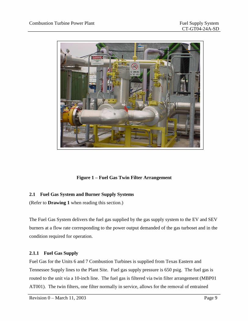
Fuel Oil Sump
The Fuel Oil Sump is equipped with a Fuel Oil Sump Pump. The Fuel Oil Sump is illustrated on
Figure 4. The Fuel Oil Sump Pump is 460 VAC motor driven and equipped with a motor heater.
The motor heater is in service whenever the pump is out of service. The Fuel Oil Sump Pump
starts and stops as required, maintaining the level in the fuel oil sump. The sump pump starts
when the level in the sump reaches the level switch LS MBN35 CL001 (at greater than 400 mm).
As soon as the sump level drops below the lower level, less than 250 mm, the pump shuts down.
Level alarms are provided. MBL35 CL003, a sump high level switch functions to initiate a
second ON command to the pump and initiates an alarm in the control room. If the level in the
tank continues to rise, reaching the maximum level, level switch (MBL34 CL004) actuates and
initiates load shedding of the gas turboset.
Twin Filters
The fuel oil is filtered via twin filter arrangement (MBN31 AT001). The twin filters, one filter
normally in service, allows for the removal of entrained debris from the No. 2 Diesel fuel oil
supply. The inlet and outlet valves of the twin filter arrangement are ganged together, allowing
flow to the filters to be swapped in a single action. Each filter is equipped with a vent and drain
valve arrangement. Differential pressure is measured across each filter and is indicated locally.
Increased differential pressure is indicative of filter cleanliness, indicating the need to swap to
the alternate filter. A differential pressure alarm for each filter is also is provided, alarming at
0.8 bar. Vents and drains are provided for each filter, routing to the Fuel Oil Sump.

Combustion Turbine Power Plant Fuel Supply System
CT-GT04-24A-SD
Revision 0 – March 11, 2003 Page 18
Figure 5 – Fuel Oil Pump
Fuel Oil Pump
Filtered oil routes to the Fuel Oil Pump (MBN32 AP001). The Fuel Oil Pump is illustrated on
Figure 5. Pressure and temperature upstream of the pump are measured. MBN31 CP003
measures the pressure before the pump.. During startup, MBN31 CP003 prevents startup
program progress until such time as the pressure has reached its preset minimum pressure.
During turboset operation (while firing with fuel oil) if pressure drops below minimum, an alarm
is initiated in the control room. MBN 31 CP004 is provided to measure and locally indicate Fuel
Oil Pump supply pressure. The Fuel Oil Pump boosts the pressure of the fuel oil to 133 Bar for
delivery to the EV and SEV Combustors. A minimum flow valve and flow integrator are
provided. The minimum flow valve (MBN32 AA001) protects the fuel oil pump from
overheating. Until the gas turboset requires a preset fuel flow, a portion of the fuel flows
through the valve, through the fuel oil return system and back to the main fuel oil tank.
Combustion Turbine Power Plant Fuel Supply System
CT-GT04-24A-SD
Revision 0 – March 11, 2003 Page 19
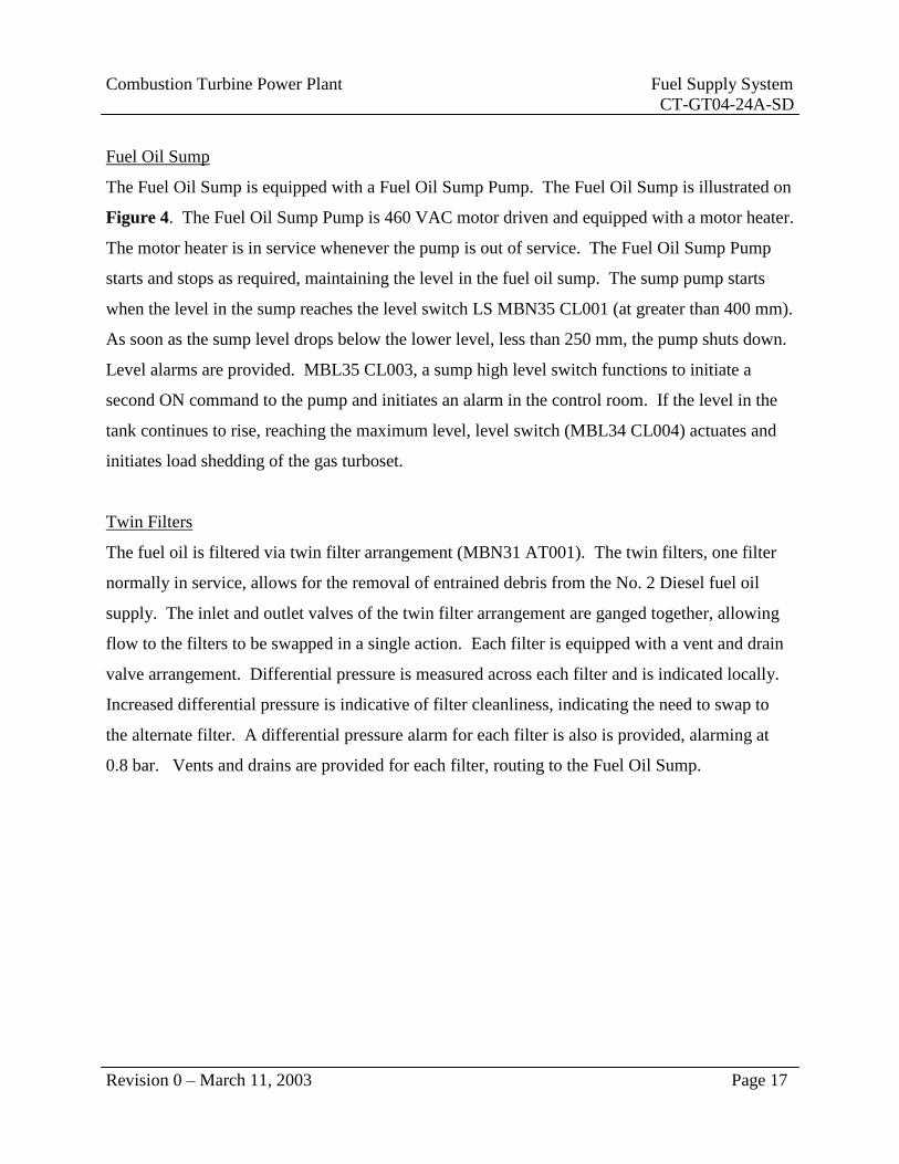
(MBN32 CF001), is an orifice type fuel flow element. The total fuel delivered is displayed in
the control room. Pressure after the fuel pump is measured and displayed in the control room.
MBN32 CP001 and CP002 are the measuring devices. If the pressure in at least one of these
instruments drops below the low level, a control room alarm actuates. If the pressure in at least
one of these instruments drops below the low-low pressure level, turboset load shedding occurs.
Figure 6 – Fuel Oil Control Block
2.2.2 Fuel Oil Control Block
The fuel oil from the fuel oil block routes to the fuel oil trip valve (MBN40 AA001). This is the
first valve in the Fuel Oil Control Block. The trip valve is hydraulically actuated to the open
position from its servomotor and is closed via spring pressure. The trip valve acts to isolate or
allow flow to the trip/shutoff valves and control valves supplying fuel oil to the EV and SEV
combustors.

Combustion Turbine Power Plant Fuel Supply System
CT-GT04-24A-SD
Revision 0 – March 11, 2003 Page 20
The following valves are equipped with servomotors and are grouped together on the Fuel Oil
Control Block:
Trip valve (MBN40 AA001)
Control valve (MBN41 AA001)
Control valve (MBN42 AA001)
The control valves are positioned via their associated servomotors, controlled by electrohydraulic
transducers MBN41 AU001 and MBN42 AU001. Power oil from the power oil system MBX44
operates the servomotors.
Additionally, the following valves are operated by control air and are grouped together on the
fuel oil control block.
Shutoff Valve to SEV Combustor (MBN42 AA010)
Fuel Oil Drain Valve (MBN50 AA001)
Fuel Oil Drain Valve (MBN51 AA001)
Fuel Oil Drain Valve (MBN52 AA001)
Pilot valves MBN41 AA101, AA201, AA301, AA401, AA501 and AA601 for the EV burners
and MBN42 AA101, AA201, AA301, AA401, AA501, and AA601 for SEV burners are
normally closed by spring force.
For deaeration of the fuel oil lines, solenoid valve MBX36 AA045 changes over. Pilot valves
MBN41 AA101 of sector 1 and MBN41 AA201 of sector two (2) OPEN. The air is blown
through these sector valves into the EV combustor. Heater MBN 36 AH010 maintains the
temperature in the fuel oil block at or above the preset value. Fan MBN36 AN001 ventilates the
fuel oil block during operation of the turboset.
Pressure limiting valve MBN31 DP001 is installed in the branch line before the fuel oil twin
filter. One of the twin filters is normally in service. Manual changeover between the two (2)
filter vessels is attained using changeover valve MBN31 AA012. The filter vessel that is not in

Combustion Turbine Power Plant Fuel Supply System
CT-GT04-24A-SD
Revision 0 – March 11, 2003 Page 21
service is available for cleaning is emptied through return lines using drain valve MBN31
AA005 and AA021 or MBN31 AA006 and AA022, during gas turboset operation. The
corresponding vent valve, MBN31 AA007 or AA008 has to be opened.
On refilling, during changeover, the filter vessel placed in operation must be deaerated using its
associated vent valve (MBN31 AA007 or AA008). The drain valves must be closed prior to
filling.
During normal operation all vent and drain valves of the filter are closed. Measurement of fuel
oil flow is quantified using a flow meter (MBN32 CF001), installed after the minimum flow
valve (MBN11001).
Orifice MBN35 BP005 is used for continuous deaeration of the sump pump. The uncooled air
for the air blast system (MBH72) is supplied from HP cooling air. This air flows through the EV
burners into the combustor and atomizes the fuel oil in the EV burners. The air supplied from
the burner carrier air system (MBH70) to SEV burners cools the SEV burners and also maintains
optimum combustion in the SEV combustor.
Shutoff Valve MBH70 AA001 and Purge Valve MBH70 AA002 are OPEN. Purge valve
MBH70 AA003 is CLOSED. A portion of the air from system MBH70 flows through the
shutoff and purge valves (MBH70 AA001 and AA002) before the distribution pipes into fuel gas
control MBP42. Then the air flows through fuel gas distribution and SEV burners into the SEV
combustor. This prevents hot gas from entering and coking/clogging the gas nozzles of the SEV
burners.

Combustion Turbine Power Plant Fuel Supply System
CT-GT04-24A-SD
Revision 0 – March 11, 2003 Page 22
3.0 System Operation
Chapter Objectives:
Describe the GT24A Fuel Supply System during:
- System Startup
- Normal Operation
- System Shutdown
NOTE: This system operation section is included for instructional purposes only,
and should not be used as an operating procedure.
3.1 System Startup
The Fuel Supply System must be available for service prior to starting the Combustion Turbine.
It is necessary to verify that all equipment clearance orders have been removed and that air
intake equipment is available for service. All confined space entry permits must be removed
with manways bolted up tight. Twin Filters must be verified as available for service. Valve
alignments must be inspected. All relay system trips must be reset. Any standing alarms must
be cleared.
Fuel Gas Supply System
When “Automatic Start Gas” is selected, startup of the turboset begins. Relief valves (MBP31
AA002, MPB51 AA001, MBP52 AA001 and MBP53 AA001) CLOSE. Main Shutoff valves
(MBP31 AA001 and MBP32 AA001) both OPEN. Gas flows to the trip valves (MBP41 AA001,
MBP42 AA001, and MBP43 AA001). These valves are CLOSED. The following message
appears “Main shutoff valves OPEN and gas relief valves CLOSED”, enabling the startup
program to continue.
The variable guide vane rows OEPN to startup position. When ignition speed is reached, trip
valves (MBP41 AA001, MBP42 AA001 and MBP43 AA001) OPEN. When MBP41 AA001
leaves the CLOSED position, the three (3) flame monitors (MBM11 CR001, CR002, and
CR003) are unblocked. Ignition with fuel gas MBP60, ignition fuel system MBQ 30, control air

Combustion Turbine Power Plant Fuel Supply System
CT-GT04-24A-SD
Revision 0 – March 11, 2003 Page 23
system MBX36 (auxiliary air for ignition torches) and the ignition torches (MBM11 AA211 and
AA631) are activated. The ignition fuel lights off.
When the temperature measured at the ignition torches exceeds the preset differential
requirement in a preset time frame, the enable to proceed signal is issued for continuation of the
starting program.
The main ignition sequence is unblocked. Control Valve MBP43 AA002 for EV pilot gas
OPENS to the ignition position (gas flow for main ignition). The gas required for main ignition
flows into the EV Combustor through fuel gas control MBP43 and the EV Burners, where it
ignites from the flames of the ignition torches.
The ignition gas system and auxiliary air system shut off. The valves return to their “At Rest”
position. Control Valve MBP43 AA002 continues to slowly OPEN. The fuel flow increases and
the speed of the gas turboset increases to nominal speed and is subsequently loaded.
Fuel Oil
While the gas turboset is at standstill, fuel oil pump MBN32 AP001 is out of service (standstill).
Main shutoff valves, the trip valve, and control valves are CLOSED.
After “Automatic Start Fuel Oil” is selected, the main shutoff valve (MBN31 AA001) OPENS.
Fuel oil pressure builds up as far as fuel oil pump (MBN32 AP001). After the pressure has
reached its preset level, the fuel pump starts, increasing pressure for operation up to the trip valve
(MBN40 AA001).
To protect the fuel pump from overheating, due to cavitation, minimum flow valve (MBN32
AA001), directs the minimum flow through the return system back through the return system to
its source, the fuel oil tank.

Combustion Turbine Power Plant Fuel Supply System
CT-GT04-24A-SD
Revision 0 – March 11, 2003 Page 24
The reverse flow opening in this valve closes automatically when the flow to the combustor is
adequate to prevent fuel oil pump overheating.
Pilot valves, oil for EV burners (MBN41 AA101, AA201, AA301, AA401, AA501, and
AA601), fuel oil drain valves (MBN50 AA001 MBN51 AA001 and MBN52 AA001) remain
CLOSED. The turboset’s variable guide vane rows OPEN to their start position. When ignition
speed is reached, trip valve (MBN40 AA001) and shutoff valve (MBN42 AA010) OPEN. Drain
valves (MBN50 AA001, MBN51 AA001 and MBN52 AA001) CLOSE.
When the trip valve leaves the CLOSED position, the three (3) flame monitors (MBM11 CR001,
CR002, and CR003) are unblocked.
Ignition fuel system (MBQ30) and Control Air System (MBX36-auxiliary air for ignition
torches) are placed in service and the ignition torches are actuated. The ignition fuel lights off.
When temperature measured at the ignition torches exceeds its temperature minimum, within a
preset time delay, the enable signal is issued for continuation of the starting program.
For quick deaeration of the fuel oil control (MBN41) solenoid valve MBX36 AA045 changes
over, control air flows to the pilot valves (MBN41 AA101 and AA201) of sectors 1 and 2 and
opens the valves. Control valve MBN41 AA001 OPENS completely for a given time frame.
The fuel oil flows in the fuel oil control and presses the air through the pilot valves (MBN41
AA101 and AA201) and the bypass orifices to pilot valves (MBN41 AA301, AA401, AA501,
and AA601) and the EV burners into the EV combustor. Control Valve MBN41 AA001
CLOSES to minimum (oil flow for main ignition). The oil for main ignition flows through the
EV burners into the EV combustor where it is atomized by the air blast system. It ignites by the
flames of the ignition torches (MBM11 AV211 and AV631).
The ignition gas system (MBQ30), the auxiliary air system (MBX36) are shut off. The valves
return to their “At Rest” position. The ignition torches (MBM11 AV211 and AV631) shut off.

Combustion Turbine Power Plant Fuel Supply System
CT-GT04-24A-SD
Revision 0 – March 11, 2003 Page 25
If at least two (2) of the three (3) flame monitors detect the flames, the enable signal is provided
for continuation of the starting sequence.
Control valve MBN41 AA001 continues to OPEN slowly. The fuel flow increases and the gas
turboset is brought up to nominal speed and loading.
3.2 Normal Operation
Fuel Gas
During low load operation, EV burners are supplied fuel gas via control MBP43. As TAT1
reaches a preset value, fuel gas control MBP41 starts to supply fuel gas. Control Valve MBP41
AA001 starts to OPEN and control valve MBP43 AA002 starts to simultaneously CLOSE until
all gas is supplied by MBP41. During this transition, the two (2) control valves are controlled
using the sum of the gas supplied to maintain a constant loading gradient.
Control Valve MBP41 AA0012 continues to slowly OPEN. The fuel flow and turboset power
output increase. As a higher preset TAT1 is reached, the SEV burners start to operate. Control
Valve MBP42 AA0021 starts to OPEN and supplies fuel gas to the SEV burners. The gas for the
SEV burners ignites due to the hot gases coming from the EV combustor. The air supplied by
the burner carrier air system (MBH70) cools the SEV burners and maintains optimum
combustion in the SEV combustor.
During operation, control valves (MBP41 AA002, MBP42 AA002, and MBP43 AA002) regulate
the supply of gas according to the power output demand. Turbine inlet temperature is monitored
and limited to its maximum value.
Fuel Oil
Under lower load, the EV burners are supplied by fuel oil control (MBN41) and the SEV burners
are not in operation. When a preset level for TAT1 is reached, SEV burners start to operate.
Pilot valves (MBN42 AA101, AA201, AA301, AA401, AA501, and AA601) remain CLOSED.

Combustion Turbine Power Plant Fuel Supply System
CT-GT04-24A-SD
Revision 0 – March 11, 2003 Page 26
Control valve MBN42 AA001 OPENS to minimum stroke. Fuel flows in the supply lines for the
SEV Burners and pressurizes the air remaining in the lines through the bypasses to pilot valves
and the SEV burners into the SEV combustor. When a preset fuel oil pressure after the control
valve is reached, indicating the supply lines are filled with fuel oil, pilot valves for SEV burners
OPEN, the fuel flows into the SEV combustor. The oil for the SEV burners ignites from the hot
gasses exiting from the EV combustor. The air supplied by burner carrier air system (MBH70)
cools the SEV burners, maintains an optimum combustion in SEV combustor (MBM20) and
prevents hot gasses from entering the fuel gas control (MBP42).
While the turboset is in operation, control valves (MBN41 AA001 and MBN42 AA001) regulate
the supply of fuel oil according to the power output demand. The turbine inlet temperature
operates as the control mode.
Should the power output drop below its preset minimum load, control valve MBN42 AA001
CLOSES and the SEV burners shut off. SEV Combustor is then out of service.
After shutdown of the SEV burners, purge valves (MBU42 AA015 and AA016) OPEN
according to the purging sequence. Water flows through the pilot valves (MBU42 AA101,
AA201, AA301, AA401, AA501, and AA601), non-return supply lines of the SEV burners and
purges the remaining oil from the lines to prevent coking of the oil lances. When the power
output increases again, the SEV combustor is returned to service.
Leakages from control valves (MBN41 AA001 and MBN42 AA001), trip valve (MBN40
AA001), shutoff valve (MBN42 AA010), and valves (MBN50 AA001, MBN51 AA001 and
MBN52 AA001) flow through fuel oil drain (MBN50) into the fuel oil sump/tank (MBN35
BB001). The centrifugal extractor (MBN35 BT001) separates fuel from the air.
Fuel samples may be taken or the leakage flow from the valves in the fuel oil control measured at
the changeover valve (MBN50 AA002).

Combustion Turbine Power Plant Fuel Supply System
CT-GT04-24A-SD
Revision 0 – March 11, 2003 Page 27
Leakage from the pump is sent directly to the tank (MBN35 BB001). When fuel reaches the set
upper level, the pump (MBN35 AP001) switches on and pumps the fuel from the sump tank
through the fuel return system (MBN34) into the selected Fuel Oil Storage tank.
When the fuel has dropped to its lower level, the pump switches OFF.
To avoid load shedding during emergency, fuel leakage can be drained through the shutoff valve
(MBN35 AA005).
3.3 System Shutdown
Fuel Gas Operation
During normal shutdown:
Load is removed by slowly closing control valves (MBP41 AA002 and MBP42 AA002). When
TAT1 drops below a preset level, control valve MBP42 AA002 CLOSES completely and the
SEV combustor shuts off.
When TAT1 drops further below another preset level, control valve MBP41 AA002 CLOSES
and control valve MBP43 AA002 OPENS. During this transition, the two (2) control valves are
controlled such that the sum of the gas supplied maintains a constant deloading gradient of the
turboset.
After idling for five minutes, the gas turboset is tripped and runs down. Control Valve MBP43
AA002, trip valves (MBP41 AA001, MBP42 AA001 and MBP43 AA001) CLOSE. Relief
Valves (MBP51 AA001, MBP52 AA001 and MBP53 AA001) OPEN, relieving the line pressure
between the trip and control valves.
Main Shutoff Valves (MBP31 AA001 and MBP32 AA001) CLOSE and relief valves (MBP31
AA001 and MBP32 AA002) OPEN, relieving pressure tripped between the main shutoff valves
and the trip valves.

Combustion Turbine Power Plant Fuel Supply System
CT-GT04-24A-SD
Revision 0 – March 11, 2003 Page 28
Fuel Oil Operation
Initially load is reduced by closing the control valves (MBN41 AA001 and MBN42 AA001).
When TAT1 drops below a preset level, control valve MBN42 AA001 CLOSES completely and
the SEV burners are shut off. After the SEV burners shutdown, purge valves (MBU42 AA015
and AA016) OPEN to purge the burners. Water flows through the pilot valves (MBU42 AA101,
AA201, AA301, AA401, AA501, and AA601) and non-return valves (MBU42 AA110, AA210,
AA310, AA410, AA510, and AA610) into the fuel oil supply line of the SEV burners, purging
the oil remaining in this line out into the combustor, to prevent coking of the oil lances.
Control valve MBN41 AA001 to the EV burners continues to CLOSE until the machine is in
idle. After five minutes on idle, the turboset trips and runs down. Control Valve MBN41
AA001, trip valve MBN40 AA001, and shutoff Valve MBN42 AA010 all CLOSE.
Shutoff Valve MBH72 AA001 of the Air Blast System (MBH72) CLOSES.
After the trip, purge valves (MBU41 AA015 and AA016) OPEN according to the purge
sequence. Purge water routes through the non-return valves MBU41 AA101 and AA110,
AA201 and AA210, AA301 and AA310, AA401 and AA410, AA501 and AA510, AA601 and
AA610), the fuel oil supply lines of the EV burners and purges the oil remaining in these lines
out of the EV combustor, to prevent coking of the oil lances.
The Fuel Pump (MBN31 AP001) shuts off and the shutoff valve (MBN31 AA001) CLOSES.
Relief Valves (MBN50 AA001, MBN51 AA001 and MBN52 AA001) OPEN, relieving the
pressure in their associated lines between the trip valve and the pilot valves into the fuel drain.

Combustion Turbine Power Plant Fuel Supply System
CT-GT04-24A-SD
Revision 0 – March 11, 2003 Page 29
4.0 References
ABB Gas Turbine Manual GT24A
ABB Operations Training Manual Volume I
ABB Operations Training Manual Volume II
ABB Operation/Electrical Maintenance Volume
ABB GT# 7 Protection Sheets

Revision 0 – March 11, 2003 Page 30
Dirt Trap
MBP32
AT001
Fuel Gas Supply
M M
M M
Fuel Gas To SEV Combustor
To EV Combustor Vent
MBP32
AA002 MBP31
AA002
Main Shutoff
MBP31
AA001
Main Shutoff
MBP32
AA001
Twin Filter
MBP01
AT001
Throttle Vv
MBP41
AA002
Dirt Trap
MBP31
AT001
Trip/Shutoff Vv
MBP42
AA001
Throttle Vv
MBP42
AA002
Relief/vent
Valve MBP52
AA001
Relief/Vent
Valve MBP51
AA001
Trip/Shutoff Vv
MBP41
AA001
Trip/Shutoff Vv
MBP43
AA003
Trip/Shutoff Vv
MBP60
AA010
Relief/Vent
Valve MBP53
AA001
Throttle Vv
MBP43
AA002
EV Pilot
EV Combustor
SEV Combustor
Relief/Vent
Valve MBP60
AA030
Ignition Gas
Vent Over
Roof
Drawing 1 – Fuel Gas System Simplified Diagram
Throttle Vv
MBP60
AA020

Revision 0 – March 11, 2003 Page 31
Drawing 2 - Fuel Oil Building Simplified Diagram
Fuel Oil Supply
M
M
Fuel Oil Return
Twin Filter
Vents and
Drains
Twin Filters
MBN31 AT001
Main Fuel Oil
Shut off Valve
MBN31
AA001
LP Pressure Limiting Valve
MBN31 DP001
Fuel Oil Sump
M
Fuel Oil Pump
MBN32 AP001
Minimum
Flow Orifice
MBN32 BP011
Minimum
Flow Valve
MBN32 AA001
Sump Pp
MBN35
AP001
Fuel Water
Return
M
Fuel Oil Building
Heating and Ventilation System
MBN36 AN001
Fuel Oil System
From Fuel Pump

Revision 0 – March 11, 2003 Page 32
Fuel Oil
Supply Header
Fuel Oil Sump
Trip/Shutoff Valve
MBN40 AA001
Fuel Oil Drain Valve
MBN50 AA001
Control Valve
MBN41 AA001
Shutoff Valve
MBN42 AA010
Fuel Oil
To EV Combustor
Fuel Oil To
SEV Combustor
Fuel Oil Drain Valve
MBN51 AA001
Fuel Oil Drain Valve
MBN52 AA001
Control Valve
MBN42 AA001
Drawing 3 - Fuel Oil Supply Simplified Diagram

Revision 0 – March 11, 2003
Page 33
FUEL SUPPLY SYSTEM
SYSTEM OPERATING PROCEDURE (CT-GT04-24A-SOP)
Combustion Turbine Plant
March 11, 2003

Combustion Turbine Fuel Supply System
CT-GT02-24A-SOP
Revision 0 – March 11, 2003 Page 1
PREFACE
This System Operating Procedure has been designed to assist you in meeting the requirements of
Module (CT-GT04-24A) of the Plant Operator Training Program. It contains information about
operation of the Fuel Supply System. This includes purpose, safety, environmental impact
and/or required regulations, training and responsibilities, precautions, limits and setpoints,
references, and procedures for operating the system equipment.
You should also walk down the system and identify the components and controls. Should you
have additional questions about system operation, ask your supervisor.
All activities that could result in the release of hazardous materials to the environment should be
performed with care and due regard for impact on the environment.

Combustion Turbine Fuel Supply System
EWB-GT02-24A-SOP
Revision 0 - March 11, 2003 Page 2
FUEL SUPPLY
SYSTEM OPERATING PROCEDURE
TABLE OF CONTENTS
I. Purpose............................................................................................................................... 3
II. Precautions, Limitations and Setpoints .......................................................................... 3
III. Procedure ........................................................................................................................... 4
A. Normal System Startup .................................................................................................... 4
B. Fuel Supply System Normal Operation .......................................................................... 8
C. Shutdown of the Fuel Supply System ............................................................................ 12
IV. References ........................................................................................................................ 14
Appendix I Fuel Supply System Valve List .............................................................................. 15

Combustion Turbine Fuel Supply System
EWB-GT02-24A-SOP
Revision 0 - March 11, 2003 Page 3
I. Purpose
A. This procedure provides information and guidance for the correct and safe operation of
the Fuel Supply System.
II. Precautions, Limitations and Setpoints
A. Verify that all maintenance work is completed and all protection orders and tags
are released and removed.
B. All confined space entry permits must be released/removed prior to startup.
C. All manways must be bolted up tight prior to startup.
D. Perform Prestartup Check list.
E. The Fuel Supply System must be available for service prior to starting the
Combustion Turbine.
F. Twin Filters must be filled and vented, with drains closed prior to startup.
G. Electrical Distribution System must be energized.
H. 125 VDC System must be in service.
I. Air Intake System must be available for service.
J. Lube Oil System must be in service.
K. Power Oil System must be in service.
L. Control Air must be available.
M. Fuel Gas Supply Pressure is controlled to a pressure no lower than 650 psi.
N. Fuel Gas Twin filter DP (Differential At Which Fuel Oil Filters Are Swapped) -
Eight (8) Bar.
O. Fuel Gas Pressure Limiting Valve (located downstream of the twin filter
arrangement set pressure) controls pressure to a pressure of 25 Bar.
P. LP Fuel Oil Pressure Limiting Valve controls pressure to a value of 1.7 Bar.
Q. Fuel Oil Sump Level Alarms - low alarm is set to actuate at less than 250 mm.
The high alarm actuates at greater than 400 mm.

Combustion Turbine Fuel Supply System
EWB-GT02-24A-SOP
Revision 0 - March 11, 2003 Page 4
III. Procedure
A. Normal System Startup
Fuel Gas Firing
__1. Verify valve alignments are in startup positions
__2. Verify that all instrumentation in the Fuel Gas System is operable as
required for service.
__3. EGATROL must be available – not tripped (CJP00EW001.)
__4. Verify all relay system trips are reset.
__5. Any standing alarms must be cleared.
__6. When “Automatic Start Gas” is selected, startup of the turboset begins.
__7. Relief valves (MBP31 AA002, MPB51 AA001, MBP52 AA001 and MBP53
AA001) CLOSE.
__8. Main Shutoff valves (MBP31 AA001 and MBP32 AA001) both OPEN.
__9. Gas flows to the trip valves (MBP41 AA001, MBP42 AA001, and MBP43
AA001). These valves are CLOSED. “
__10. Main shutoff valves OPEN and gas relief valves CLOSED” message appears,
enabling the startup program to continue.
__11. The variable guide vane rows OPEN to startup position.

Combustion Turbine Fuel Supply System
EWB-GT02-24A-SOP
Revision 0 - March 11, 2003 Page 5
__12. When ignition speed is reached, trip valves (MBP41 AA001, MBP42 AA001
and MBP43 AA001) OPEN.
__13. When MBP41 AA001 leaves the CLOSED position, the three (3) flame
monitors (MBM11 CR001, CR002, and CR003) are unblocked.
__14. Ignition with fuel gas MBP60, ignition fuel system MBQ 30, control air
system MBX36 (auxiliary air for ignition torches) and the ignition torches
(MBM11 AA211 and AA631) are activated.
__15. The ignition fuel lights off.
__16. When the temperature measured at the ignition torches exceeds the preset
differential requirement in a preset time frame, the enable to proceed signal is
issued for continuation of the starting program.
__17. The main ignition sequence is unblocked.
__18. Control Valve MBP43 AA002 for EV pilot gas OPENS to the ignition
position (gas flow for main ignition).
__19. The gas required for main ignition flows into the EV Combustor through fuel
gas control MBP43 and the EV Burners, where it ignites from the flames of
the ignition torches.
__20. The ignition gas system and auxiliary air system shut off.
__21. The valves return to their “At Rest” position.

Combustion Turbine Fuel Supply System
EWB-GT02-24A-SOP
Revision 0 - March 11, 2003 Page 6
__22. Control Valve MBP43 AA002 continues to slowly OPEN.
__23. The fuel flow increases and the speed of the gas turboset increases to nominal
speed and is subsequently loaded.
Fuel Oil Firing
__1. After “Automatic Start Fuel Oil” is selected, the main shutoff valve (MBN31
AA001) OPENS.
__2. Fuel oil pressure builds up as far as fuel oil pump (MBN32 AP001).
__3. After the pressure has reached its preset level, the fuel pump starts, increasing
pressure for operation up to the trip valve (MBN40 AA001).
__4. To protect the fuel pump from overheating, due to cavitation, minimum flow
valve (MBN32 AA001), directs the minimum flow through the return system
back through the return system to its source, the fuel oil tank.
__5. The reverse flow opening in this valve closes automatically when the flow to
the combustor is adequate to prevent fuel oil pump overheating.
__6. Pilot valves, oil for EV burners (MBN41 AA101, AA201, AA301, AA401,
AA501, and AA601), fuel oil drain valves (MBN50 AA001 MBN51 AA001
and MBN52 AA001) remain CLOSED.
__7. The turboset’s variable guide vane rows OPEN to their start position.
__8. When ignition speed is reached, trip valve (MBN40 AA001) and shutoff valve
(MBN42 AA010) OPEN.

Combustion Turbine Fuel Supply System
EWB-GT02-24A-SOP
Revision 0 - March 11, 2003 Page 7
__9. Drain valves (MBN50 AA001, MBN51 AA001 and MBN52 AA001)
CLOSE.
__10. When the trip valve leaves the CLOSED position, the three (3) flame monitors
(MBM11 CR001, CR002, and CR003) are unblocked.
__11. Ignition fuel system (MBQ30) and Control Air System (MBX36-auxiliary air
for ignition torches) are placed in service and the ignition torches are
activated. The ignition fuel lights off.
__12. When temperature measured at the ignition torches exceeds its temperature
minimum, within a preset time delay, the enable signal is issued for
continuation of the starting program.
__13. For quick deaeration of the fuel oil control (MBN41) solenoid valve MBX36
AA045 changes over.
__14. Control air flows to the pilot valves (MBN41 AA101 and AA201) of sectors 1
and 2 and opens the valves.
__15. Control valve MBN41 AA001 OPENS completely for a given time frame.
The fuel oil flows in the fuel oil control and presses the air through the pilot
valves (MBN41 AA101 and AA201) and the bypass orifices to pilot valves
(MBN41 AA301, AA401, AA501, and AA601) and the EV burners into the
EV combustor.
__16. Control Valve MBN41 AA001 CLOSES to minimum (oil flow for main
ignition).

Combustion Turbine Fuel Supply System
EWB-GT02-24A-SOP
Revision 0 - March 11, 2003 Page 8
__17. The oil for main ignition flows through the EV burners into the EV
combustor.
__18. It ignites by the flames of the ignition torches (MBM11 AV211 and AV631).
__19. The ignition gas system (MBQ30), the auxiliary air system (MBX36) are shut
off. The valves return to their “At Rest” position.
__20. The ignition torches (MBM11 AV211 and AV631) shut off.
__21. If at least two (2) of the three (3) flame monitors detect the flames, the enable
signal is provided for continuation of the starting sequence.
__22. Control valve MBN41 AA001 continues to OPEN slowly. The fuel flow
increases and the gas turboset is brought up to nominal speed and loading.
B. Fuel Supply System Normal Operation
Fuel Gas Firing
__1. Monitor Filter differential pressure.
__2. Monitor Fuel Gas Header Pressure
__3. During low load operation, EV burners are supplied fuel gas via control
MBP43.
__4. At a pre-determined TAT1, fuel gas control MBP41 starts to supply fuel gas.
Control Valve MBP41 AA001 starts to OPEN and control valve MBP43
AA002 starts to simultaneously CLOSE until all gas is supplied by MBP41.

Combustion Turbine Fuel Supply System
EWB-GT02-24A-SOP
Revision 0 - March 11, 2003 Page 9
__5. During this transition, the two (2) control valves are controlled using the sum
of the gas supplied to maintain a constant loading gradient.
__6. Control Valve MBP41 AA0012 continues to slowly OPEN. The fuel flow and
turboset power output increase.
__7. As TAT1 further increases, the SEV burners start to operate. Control Valve
MBP42 AA0021 starts to OPEN and supplies fuel gas to the SEV burners.
__8. The gas for the SEV burners ignites due to the hot gases coming from the EV
combustor. The air supplied by the burner carrier air system (MBH70) cools
the SEV burners and maintains optimum combustion in the SEV combustor.
__9. During operation, control valves (MBP41 AA002, MBP42 AA002, and
MBP43 AA002) regulate the supply of gas according to the power output
demand. Turbine inlet temperature is monitored and limited to its maximum
value.
Fuel Oil Firing
__1. During Fuel Oil Firing, under lower load, the EV burners are supplied by fuel
oil control valve (MBN41) and the SEV burners are not in operation.
__2. When the preset TAT1 value is reached, SEV burners start to operate.
__3. Pilot valves (MBN42 AA101, AA201, AA301, AA401, AA501, and AA601)
remain CLOSED.
__4. Control valve MBN42 AA001 OPENS to minimum stroke.

Combustion Turbine Fuel Supply System
EWB-GT02-24A-SOP
Revision 0 - March 11, 2003 Page 10
__5. Fuel flows in the supply lines for the SEV Burners and pressurizes the air
remaining in the lines through the bypasses to pilot valves and the SEV burners
into the SEV combustor.
__6. When a preset fuel oil pressure after the control valve is reached, indicating the
supply lines are filled with fuel oil, pilot valves for SEV burners OPEN, and
fuel flows into the SEV combustor.
__7. The oil for the SEV burners ignites from the hot gasses exiting from the EV
combustor.
__8. The air supplied by burner carrier air system (MBH70) cools the SEV burners,
maintains an optimum combustion in SEV combustor (MBM20) and prevents
hot gasses from entering the fuel gas control (MBP42).
__9. While the turboset is in operation, control valves (MBN41 AA001 and MBN42
AA001) regulate the supply of fuel oil according to the power output demand.
__10. The turbine inlet temperature operates as the control mode.
__11. Should the TAT1 drop below a preset minimum level, control valve MBN42
AA001 CLOSES and the SEV burners shut off. The SEV Combustor is then
out of service.
__12. After shutdown of the SEV burners, purge valves (MBU42 AA015 and
AA016) OPEN according to the purging sequence.

Combustion Turbine Fuel Supply System
EWB-GT02-24A-SOP
Revision 0 - March 11, 2003 Page 11
__13. Water flows through the pilot valves (MBU42 AA101, AA201, AA301,
AA401, AA501, and AA601), non-return supply lines of the SEV burners and
purges the remaining oil from the lines to prevent coking of the oil lances.
__14. When the power output increases again, the SEV combustor is returned to
service.
__15. Leakages from control valves (MBN41 AA001 and MBN42 AA001), trip
valve (MBN40 AA001), shutoff valve (MBN42 AA010), and valves (MBN50
AA001, MBN51 AA001 and MBN52 AA001) flow through fuel oil drain
(MBN50) into the fuel oil sump/tank (MBN35 BB001).
__16. The centrifugal extractor (MBN35 BT001) separates fuel from the air.
__17. Fuel samples may be taken or the leakage flow from the valves in the fuel oil
control measured at the changeover valve (MBN50 AA002).
__18. Leakage from the pump is sent directly to the tank (MBN35 BB001).
__19. When fuel reaches the set upper level, the pump (MBN35 AP001) switches on
and pumps the fuel from the sump tank through the fuel return system
(MBN34) into the selected Fuel Oil Storage tank.
__20. When the fuel has dropped to its lower level, the pump switches OFF.
__21. To avoid load shedding during emergency, fuel leakage can be drained through
the shutoff valve (MBN35 AA005).
Combustion Turbine Fuel Supply System
EWB-GT02-24A-SOP
Revision 0 - March 11, 2003 Page 12
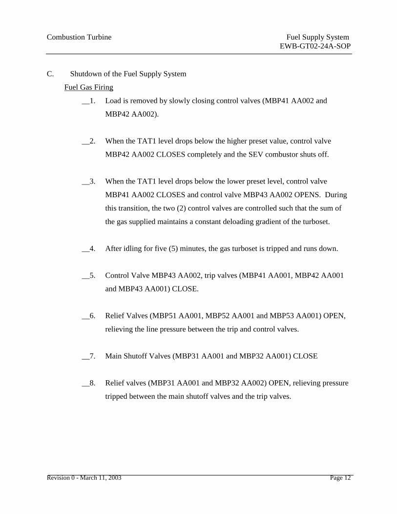
C. Shutdown of the Fuel Supply System
Fuel Gas Firing
__1. Load is removed by slowly closing control valves (MBP41 AA002 and
MBP42 AA002).
__2. When the TAT1 level drops below the higher preset value, control valve
MBP42 AA002 CLOSES completely and the SEV combustor shuts off.
__3. When the TAT1 level drops below the lower preset level, control valve
MBP41 AA002 CLOSES and control valve MBP43 AA002 OPENS. During
this transition, the two (2) control valves are controlled such that the sum of
the gas supplied maintains a constant deloading gradient of the turboset.
__4. After idling for five (5) minutes, the gas turboset is tripped and runs down.
__5. Control Valve MBP43 AA002, trip valves (MBP41 AA001, MBP42 AA001
and MBP43 AA001) CLOSE.
__6. Relief Valves (MBP51 AA001, MBP52 AA001 and MBP53 AA001) OPEN,
relieving the line pressure between the trip and control valves.
__7. Main Shutoff Valves (MBP31 AA001 and MBP32 AA001) CLOSE
__8. Relief valves (MBP31 AA001 and MBP32 AA002) OPEN, relieving pressure
tripped between the main shutoff valves and the trip valves.

Combustion Turbine Fuel Supply System
EWB-GT02-24A-SOP
Revision 0 - March 11, 2003 Page 13
Fuel Oil Firing
__1. Initially load is reduced by closing the control valves (MBN41 AA001 and
MBN42 AA001).
__2. When the TAT1 drops to a preset level, control valve MBN42 AA001
CLOSES completely and the SEV burners are shut off.
__3. After the SEV burners shutdown, purge valves (MBU42 AA015 and AA016)
OPEN to purge the burners.
__4. Water flows through the pilot valves (MBU42 AA101, AA201, AA301,
AA401, AA501, and AA601) and non-return valves (MBU42 AA110,
AA210, AA310, AA410, AA510, and AA610) into the fuel oil supply line of
the SEV burners, purging the oil remaining in this line out into the combustor,
to prevent coking of the oil lances.
__5. Control valve MBN41 AA001 to the EV burners continues to CLOSE until
the machine is in idle.
__6. After a time out in idling (5 minutes), the turboset trips and runs down.
__7. Control Valve MBN41 AA001, trip valve MBN40 AA001, and shutoff Valve
MBN42 AA010 all CLOSE.
__8. After the trip, purge valves (MBU41 AA015 and AA016) OPEN according to
the purge sequence.
__9. Purge water routes through the non-return valves MBU41 AA101 and AA110,
AA201 and AA210, AA301 and AA310, AA401 and AA410, AA501 and

Combustion Turbine Fuel Supply System
EWB-GT02-24A-SOP
Revision 0 - March 11, 2003 Page 14
AA510, AA601 and AA610), the fuel oil supply lines of the EV burners and
purges the oil remaining in these lines out of the EV combustor, to prevent
coking of the oil lances.
__10. The Fuel Pump (MBN31 AP001) shuts off and the shutoff valve (MBN31
AA001) CLOSES.
__11. Relief Valves (MBN50 AA001, MBN51 AA001 and MBN52 AA001) OPEN,
relieving the pressure in their associated lines between the trip valve and the
pilot valves into the fuel drain.
IV. References
ABB LG&E Burgin Operations Gas Turbine Manual GT24A
ABB LG&E Burgin Operations Training Manual Volume I
ABB LG&E Burgin Operations Training Manual Volume II
ABB LG&E Burgin Operation/Electrical Maintenance Volume
ABB LG&E Burgin GT# 7 Protection Sheets

Combustion Turbine Fuel Supply System
EWB-GT02-24A-SOP
Revision 0 - March 11, 2003 Page 15
Appendix I
Fuel Supply System Valve List
Valve
Number Description Startup Normal Shutdown
FUEL GAS FIRING
MBP31
AA001
Fuel Gas Main Shutoff Valve Open Open Closed
MBP32
AA001
Fuel Gas Main Shutoff Valve Open Open Closed
MBP41
AA001
Fuel Gas Trip Valve Open Open Closed
MBP42
AA001
Fuel Gas Trip Valve Open Open Closed
MBP43
AA001
Fuel Gas Trip Valve Open Open Closed
MBP41
AA002
Fuel Gas Control Valve Open Open Closed
MBP42
AA002
Fuel Gas Control Valve Open Open Closed
MBP43
AA002
Fuel Gas Control Valve Open Open Closed
MBP31
AA002
Fuel Gas Relief Valve Closed Closed Open
MBP31
AA002
Fuel Gas Relief Valve Closed Closed Open
MBP32
AA002
Fuel Gas Relief Valve Closed Closed Open
MBP51
AA002
Fuel Gas Relief Valve Closed Closed Open
MBP52
AA002
Fuel Gas Relief Valve Closed Closed Open
MBP52 Fuel Gas Relief Valve Closed Closed Open
Combustion Turbine Fuel Supply System
EWB-GT02-24A-SOP
Revision 0 - March 11, 2003 Page 16
Valve
Number Description Startup Normal Shutdown
AA002
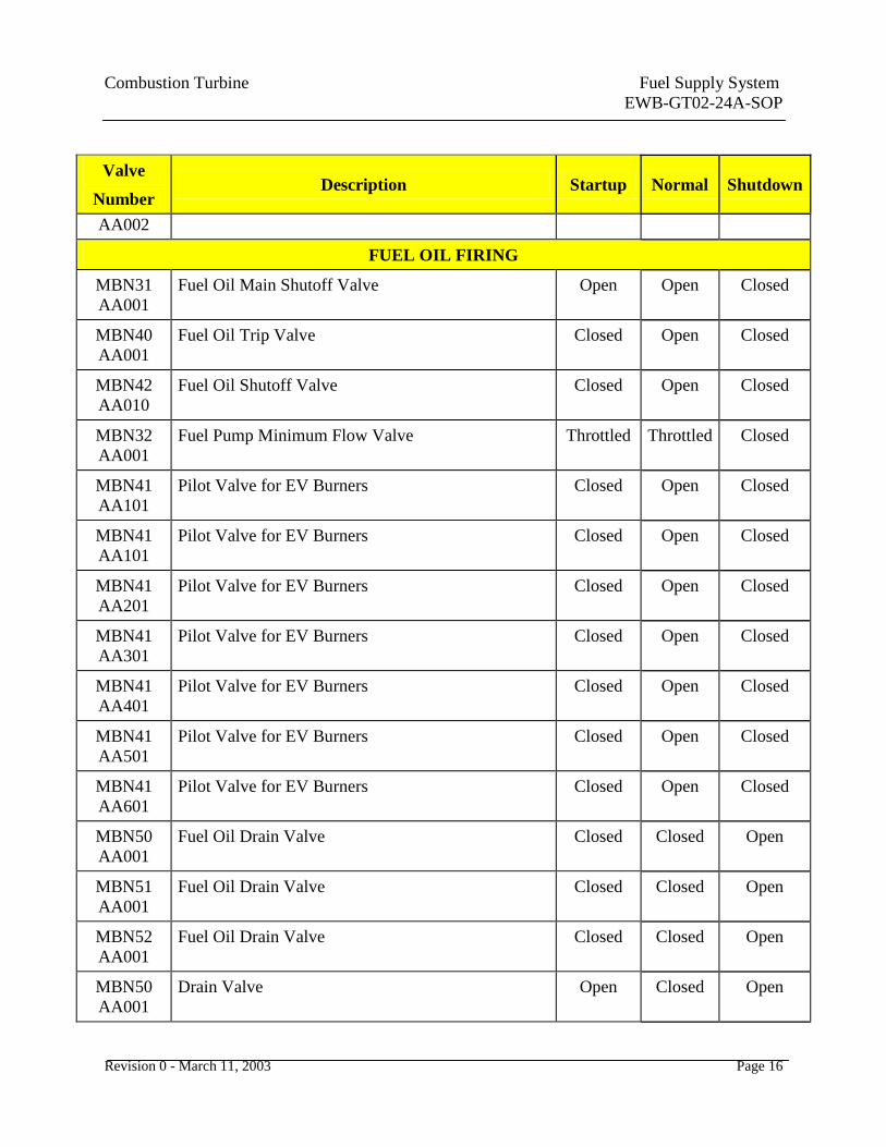
FUEL OIL FIRING
MBN31
AA001
Fuel Oil Main Shutoff Valve Open Open Closed
MBN40
AA001
Fuel Oil Trip Valve Closed Open Closed
MBN42
AA010
Fuel Oil Shutoff Valve Closed Open Closed
MBN32
AA001
Fuel Pump Minimum Flow Valve Throttled Throttled Closed
MBN41
AA101
Pilot Valve for EV Burners Closed Open Closed
MBN41
AA101
Pilot Valve for EV Burners Closed Open Closed
MBN41
AA201
Pilot Valve for EV Burners Closed Open Closed
MBN41
AA301
Pilot Valve for EV Burners Closed Open Closed
MBN41
AA401
Pilot Valve for EV Burners Closed Open Closed
MBN41
AA501
Pilot Valve for EV Burners Closed Open Closed
MBN41
AA601
Pilot Valve for EV Burners Closed Open Closed
MBN50
AA001
Fuel Oil Drain Valve Closed Closed Open
MBN51
AA001
Fuel Oil Drain Valve Closed Closed Open
MBN52
AA001
Fuel Oil Drain Valve Closed Closed Open
MBN50
AA001
Drain Valve Open Closed Open

Combustion Turbine Fuel Supply System
EWB-GT02-24A-SOP
Revision 0 - March 11, 2003 Page 17
Valve
Number Description Startup Normal Shutdown
MBN52
AA001
Drain Valve Open Closed Open
MBX36
AA045
Control Air Flow to Pilot Valves Closed Open Closed
MBN41
AA101
Pilot Valve Closed Open Closed
MBN41
AA201
Pilot Valve Closed Open Closed
MBN41
AA301
Pilot Valve Closed Open Closed
MBN41
AA401
Pilot Valve Closed Open Closed
MBN41
AA501
Pilot Valve Closed Open Closed
MBN41
AA601
Pilot Valve Closed Open Closed
MBN42
AA001
Fuel Oil Control Valve to SEV Combustor Closed Open Closed
MBN42
AA101
Fuel Oil Pilot Valve Supply To SEV Combustor Closed Open Closed
MBN42
AA201
Fuel Oil Pilot Valve Supply To SEV Combustor Closed Open Closed
MBN42
AA301
Fuel Oil Pilot Valve Supply To SEV Combustor Closed Open Closed
MBN42
AA401
Fuel Oil Pilot Valve Supply To SEV Combustor Closed Open Closed
MBN42
AA501
Fuel Oil Pilot Valve Supply To SEV Combustor Closed Open Closed
MBN42
AA601
Fuel Oil Pilot Valve Supply To SEV Combustor Closed Open Closed
MBU41 Purge Valve Closed Closed Open

Combustion Turbine Fuel Supply System
EWB-GT02-24A-SOP
Revision 0 - March 11, 2003 Page 18
Valve
Number Description Startup Normal Shutdown
AA015
MBU41
AA016
Purge Valve Closed Closed Open
MBU41
AA101
Non-Return Valve (for purging) Closed Closed Open
MBU41
AA110
Non-Return Valve (for purging) Closed Closed Open
MBU41
AA201
Non-Return Valve (for purging) Closed Closed Open
MBU41
AA210
Non-Return Valve (for purging) Closed Closed Open
MBU41
AA301
Non-Return Valve (for purging) Closed Closed Open
MBU41
AA310
Non-Return Valve (for purging) Closed Closed Open
MBU41
AA401
Non-Return Valve (for purging) Closed Closed Open
MBU41
AA410
Non-Return Valve (for purging) Closed Closed Open
MBU41
AA501
Non-Return Valve (for purging) Closed Closed Open
MBU41
AA510
Non-Return Valve (for purging) Closed Closed Open
MBU41
AA601
Non-Return Valve (for purging) Closed Closed Open
MBU41
AA610
Non-Return Valve (for purging) Closed Closed Open

Combustion Turbine Power Plant Operator– Combustion Turbine 24A
Job Performance Measure (JPM)
Page 19
Plant Operator CT-GT04-24A-JPM
Performance Measure: Fuel Supply System
Name:
All Parts Satisfactorily Completed:
(Examiner’s signature) (Date)
Supervisor’s Comments: __________________________________________________
_______________________________________________________________________
_______________________________________________________________________
_______________________________________________________________________
References:
Training Module (CT-GT04-24A)
Materials Needed:
Pencil
System Description – Fuel Supply System (CT-GT04-24A-SD)
System Operating Procedure – Fuel Supply System (CT-GT04-24A-SOP)
Associated Operator Route Checklist
Combustion Turbine Power Station Fuel Supply System P&IDs
Safety/Environmental:
Wear hard hats, safety glasses, safety toe shoes, and ear plugs as required.
Discuss safety and environmental hazards associated with operating the system.
Discuss any unusual operating conditions associated with the system.
Note: Always observe all plant safety precautions in accordance with Plant Safety and
Health procedures, the Combustion Turbine Power Station Safety and Operating
Rules and all Federal, State and/or Local OSHA Standards.
Combustion Turbine Power Plant Operator– Combustion Turbine 24A
Job Performance Measure (JPM)
Page 20
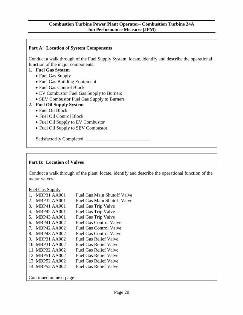
Part A: Location of System Components
Conduct a walk through of the Fuel Supply System, locate, identify and describe the operational
function of the major components.
1. Fuel Gas System
Fuel Gas Supply
Fuel Gas Building Equipment
Fuel Gas Control Block
EV Combustor Fuel Gas Supply to Burners
SEV Combustor Fuel Gas Supply to Burners
2. Fuel Oil Supply System
Fuel Oil Block
Fuel Oil Control Block
Fuel Oil Supply to EV Combustor
Fuel Oil Supply to SEV Combustor
Satisfactorily Completed ___________________________
Part B: Location of Valves
Conduct a walk through of the plant, locate, identify and describe the operational function of the
major valves.
Fuel Gas Supply
1. MBP31 AA001 Fuel Gas Main Shutoff Valve
2. MBP32 AA001 Fuel Gas Main Shutoff Valve
3. MBP41 AA001 Fuel Gas Trip Valve
4. MBP42 AA001 Fuel Gas Trip Valve
5. MBP43 AA001 Fuel Gas Trip Valve
6. MBP41 AA002 Fuel Gas Control Valve
7. MBP42 AA002 Fuel Gas Control Valve
8. MBP43 AA002 Fuel Gas Control Valve
9. MBP31 AA002 Fuel Gas Relief Valve
10. MBP31 AA002 Fuel Gas Relief Valve
11. MBP32 AA002 Fuel Gas Relief Valve
12. MBP51 AA002 Fuel Gas Relief Valve
13. MBP52 AA002 Fuel Gas Relief Valve
14. MBP52 AA002 Fuel Gas Relief Valve
Continued on next page

Combustion Turbine Power Plant Operator– Combustion Turbine 24A
Job Performance Measure (JPM)
Page 21
Part B: Continued
Fuel Oil Supply
15. MBN31 AA001 Fuel Oil Main Shutoff Valve
16. MBN40 AA001 Fuel Oil Trip Valve
17. MBN42 AA010 Fuel Oil Shutoff Valve
18. MBN32 AA001 Fuel Pump Minimum Flow Valve
19. MBN41 AA101 Pilot Valve for EV Burners
20. MBN41 AA101 Pilot Valve for EV Burners
21. MBN41 AA201 Pilot Valve for EV Burners
22. MBN41 AA301 Pilot Valve for EV Burners
23. MBN41 AA401 Pilot Valve for EV Burners
24. MBN41 AA501 Pilot Valve for EV Burners
25. MBN41 AA601 Pilot Valve for EV Burners
26. MBN50 AA001 Fuel Oil Drain Valve
27. MBN51 AA001 Fuel Oil Drain Valve
28. MBN52 AA001 Fuel Oil Drain Valve
29. MBN50 AA001 Drain Valve
30. MBN52 AA001 Drain Valve
31. MBX36 AA045 Control Air Flow to Pilot Valves
32. MBN41 AA101 Pilot Valve
33. MBN41 AA201 Pilot Valve
34. MBN41 AA301 Pilot Valve
35. MBN41 AA401 Pilot Valve
36. MBN41 AA501 Pilot Valve
37. MBN41 AA601 Pilot Valve
38. MBN42 AA001 Fuel Oil Control Valve to SEV Combustor
39. MBN42 AA101 Fuel Oil Pilot Valve Supply To SEV Combustor
40. MBN42 AA201 Fuel Oil Pilot Valve Supply To SEV Combustor
41. MBN42 AA301 Fuel Oil Pilot Valve Supply To SEV Combustor
42. MBN42 AA401 Fuel Oil Pilot Valve Supply To SEV Combustor
43. MBN42 AA501 Fuel Oil Pilot Valve Supply To SEV Combustor
44. MBN42 AA601 Fuel Oil Pilot Valve Supply To SEV Combustor
45. MBU41 AA015 Purge Valve
46. MBU41 AA016 Purge Valve
47. MBU41 AA101 Non-Return Valve (for purging)
48. MBU41 AA110 Non-Return Valve (for purging)
49. MBU41 AA201 Non-Return Valve (for purging)
50. MBU41 AA210 Non-Return Valve (for purging)
51. MBU41 AA301 Non-Return Valve (for purging)
52. MBU41 AA310 Non-Return Valve (for purging)
Continued on next page
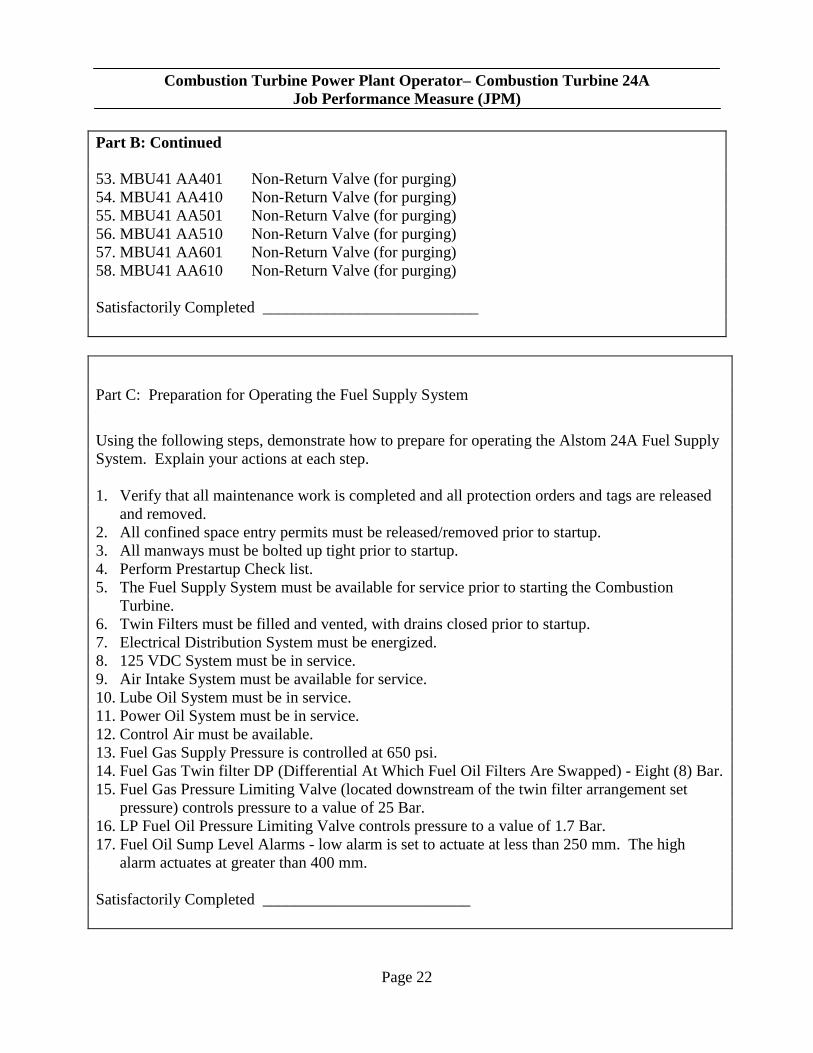
Combustion Turbine Power Plant Operator– Combustion Turbine 24A
Job Performance Measure (JPM)
Page 22
Part B: Continued
53. MBU41 AA401 Non-Return Valve (for purging)
54. MBU41 AA410 Non-Return Valve (for purging)
55. MBU41 AA501 Non-Return Valve (for purging)
56. MBU41 AA510 Non-Return Valve (for purging)
57. MBU41 AA601 Non-Return Valve (for purging)
58. MBU41 AA610 Non-Return Valve (for purging)
Satisfactorily Completed ___________________________
Part C: Preparation for Operating the Fuel Supply System
Using the following steps, demonstrate how to prepare for operating the Alstom 24A Fuel Supply
System. Explain your actions at each step.
1. Verify that all maintenance work is completed and all protection orders and tags are released
and removed.
2. All confined space entry permits must be released/removed prior to startup.
3. All manways must be bolted up tight prior to startup.
4. Perform Prestartup Check list.
5. The Fuel Supply System must be available for service prior to starting the Combustion
Turbine.
6. Twin Filters must be filled and vented, with drains closed prior to startup.
7. Electrical Distribution System must be energized.
8. 125 VDC System must be in service.
9. Air Intake System must be available for service.
10. Lube Oil System must be in service.
11. Power Oil System must be in service.
12. Control Air must be available.
13. Fuel Gas Supply Pressure is controlled at 650 psi.
14. Fuel Gas Twin filter DP (Differential At Which Fuel Oil Filters Are Swapped) - Eight (8) Bar.
15. Fuel Gas Pressure Limiting Valve (located downstream of the twin filter arrangement set
pressure) controls pressure to a value of 25 Bar.
16. LP Fuel Oil Pressure Limiting Valve controls pressure to a value of 1.7 Bar.
17. Fuel Oil Sump Level Alarms - low alarm is set to actuate at less than 250 mm. The high
alarm actuates at greater than 400 mm.
Satisfactorily Completed __________________________

Combustion Turbine Power Plant Operator– Combustion Turbine 24A
Job Performance Measure (JPM)
Page 23
Part D: 24A Fuel Supply System Startup (Using Fuel Gas)
Perform a start up of the Fuel Supply System using Fuel Gas. Explain your actions and
observations at each step of the procedure.
Fuel Gas Firing
1. Verify valve alignments are in startup positions
2. Verify that all instrumentation in the Fuel Gas System is operable as required for service.
3. EGATROL must be available – not tripped (CJP00EW001.)
4. Verify all relay system trips are reset.
5. Any standing alarms must be cleared.
6. When “Automatic Start Gas” is selected, startup of the turboset begins.
7. Relief valves (MBP31 AA002, MPB51 AA001, MBP52 AA001 and MBP53 AA001)
CLOSE.
8. Main Shutoff valves (MBP31 AA001 and MBP32 AA001) both OPEN.
9. Gas flows to the trip valves (MBP41 AA001, MBP42 AA001, and MBP43 AA001). These
valves are CLOSED. “
10. Main shutoff valves OPEN and gas relief valves CLOSED” message appears, enabling the
startup program to continue.
11. The variable guide vane rows OPEN to startup position.
12. When ignition speed is reached, trip valves (MBP41 AA001, MBP42 AA001 and MBP43
AA001) OPEN.
13. When MBP41 AA001 leaves the CLOSED position, the three (3) flame monitors (MBM11
CR001, CR002, and CR003) are unblocked.
14. Ignition with fuel gas MBP60, ignition fuel system MBQ 30, control air system MBX36
(auxiliary air for ignition torches) and the ignition torches (MBM11 AA211 and AA631) are
activated.
15. The ignition fuel lights off.
16. When the temperature measured at the ignition torches exceeds the preset differential
requirement in a preset time frame, the enable to proceed signal is issued for continuation of
the starting program.
17. The main ignition sequence is unblocked.
18. Control Valve MBP43 AA002 for EV pilot gas OPENS to the ignition position (gas flow for
main ignition).
19. The gas required for main ignition flows into the EV Combustor through fuel gas control
MBP43 and the EV Burners, where it ignites from the flames of the ignition torches.
20. The ignition gas system and auxiliary air system shut off.
21. The valves return to their “At Rest” position
Continued on Next Page

Combustion Turbine Power Plant Operator– Combustion Turbine 24A
Job Performance Measure (JPM)
Page 24
Part D - Continued
22. Control Valve MBP43 AA002 continues to slowly OPEN.
23. The fuel flow increases and the speed of the gas turboset increases to nominal speed and is
subsequently loaded.
Satisfactorily Completed __________________________
Part E: 24A Fuel Supply System Startup (Using Fuel Oil)
Perform a start up of the Fuel Supply System using Fuel Oil. Explain your actions and
observations at each step of the procedure.
Fuel Oil Firing
1. After “Automatic Start Fuel Oil” is selected, the main shutoff valve (MBN31 AA001)
OPENS.
2. Uncooled air supplied by HP cooling air system (MBH40) flows through system MBH72 and
the EV burners for combustion.
3. Fuel oil pressure builds up as far as fuel oil pump (MBN32 AP001).
4. After the pressure has reached its preset level, the fuel pump starts, increasing pressure for
operation up to the trip valve (MBN40 AA001).
5. To protect the fuel pump from overheating, due to cavitation, minimum flow valve (MBN32
AA001), directs the minimum flow through the return system back through the return system
to its source, the fuel oil tank.
6. The reverse flow opening in this valve closes automatically when the flow to the combustor
is adequate to prevent fuel oil pump overheating.
7. Pilot valves, oil for EV burners (MBN41 AA101, AA201, AA301, AA401, AA501, and
AA601), fuel oil drain valves (MBN50 AA001 MBN51 AA001 and MBN52 AA001) remain
CLOSED.
8. The turboset’s variable guide vane rows OPEN to their start position.
9. When ignition speed is reached, trip valve (MBN40 AA001) and shutoff valve (MBN42
AA010) OPEN.
10. Drain valves (MBN50 AA001, MBN51 AA001 and MBN52 AA001) CLOSE.
11. When the trip valve leaves the CLOSED position, the three (3) flame monitors (MBM11
CR001, CR002, and CR003) are unblocked.
12. Ignition fuel system (MBQ30) and Control Air System (MBX36-auxiliary air for ignition
torches) are placed in service and the ignition torches are activated. The ignition fuel lights
off.
13. When temperature measured at the ignition torches exceeds its temperature minimum, within
a preset time delay, the enable signal is issued for continuation of the starting program.
Combustion Turbine Power Plant Operator– Combustion Turbine 24A
Job Performance Measure (JPM)
Page 25
14. For quick deaeration of the fuel oil control (MBN41) solenoid valve MBX36 AA045 changes
over.
15. Control air flows to the pilot valves (MBN41 AA101 and AA201) of sectors 1 and 2 and
opens the valves.
16. Control valve MBN41 AA001 OPENS completely for a given time frame. The fuel oil flows
in the fuel oil control and presses the air through the pilot valves (MBN41 AA101 and
AA201) and the bypass orifices to pilot valves (MBN41 AA301, AA401, AA501, and
AA601) and the EV burners into the EV combustor.
17. Control Valve MBN41 AA001 CLOSES to minimum (oil flow for main ignition).
18. The oil for main ignition flows through the EV burners into the EV combustor where it is
atomized by the air blast system.
19. It ignites by the flames of the ignition torches (MBM11 AV211 and AV631).
20. The ignition gas system (MBQ30), the auxiliary air system (MBX36) are shut off. The
valves return to their “At Rest” position.
21. The ignition torches (MBM11 AV211 and AV631) shut off.
22. If at least two (2) of the three (3) flame monitors detect the flames, the enable signal is
provided for continuation of the starting sequence.
23. Control valve MBN41 AA001 continues to OPEN slowly. The fuel flow increases and the
gas turboset is brought up to nominal speed and loading.
Satisfactorily Completed ____________________________

Combustion Turbine Power Plant Operator– Combustion Turbine 24A
Job Performance Measure (JPM)
Page 26
Part F: Fuel Supply System (Fuel Gas) Inspection (Normal Operations)
Conduct a complete system inspection of the Fuel Supply System (Gas Supply). Explain your
actions and observations as equipment is inspected.
1. Monitor Filter differential pressure.
2. Monitor Fuel Gas Header Pressure
3. During low load operation, EV burners are supplied fuel gas via control MBP43.
4. As a preset level for TAT1 is reached, fuel gas control MBP41 starts to supply fuel gas.
Control Valve MBP41 AA001 starts to OPEN and control valve MBP43 AA002 starts to
simultaneously CLOSE until all gas is supplied by MBP41.
5. During this transition, the two (2) control valves are controlled using the sum of the gas
supplied to maintain a constant loading gradient.
6. Control Valve MBP41 AA0012 continues to slowly OPEN. The fuel flow and turboset
power output increase.
7. As a higher preset TAT1 level is reached, the SEV burners start to operate. Control Valve
MBP42 AA0021 starts to OPEN and supplies fuel gas to the SEV burners.
8. The gas for the SEV burners ignites due to the hot gases coming from the EV combustor.
The air supplied by the burner carrier air system (MBH70) cools the SEV burners and
maintains optimum combustion in the SEV combustor.
9. During operation, control valves (MBP41 AA002, MBP42 AA002, and MBP43 AA002)
regulate the supply of gas according to the power output demand. Turbine inlet temperature
is monitored and limited to its maximum value.
Satisfactorily Completed ____________________________
Combustion Turbine Power Plant Operator– Combustion Turbine 24A
Job Performance Measure (JPM)
Page 27
Part G: Fuel Oil System Inspection
Conduct a complete system inspection of the Fuel Supply System (Diesel Supply). Explain your
actions and observations as equipment is inspected.
1. During Fuel Oil Firing, under lower load, the EV burners are supplied by fuel oil control
valve (MBN41) and the SEV burners are not in operation.
2. When a preset level for TAT1 is reached, SEV burners start to operate.
3. Pilot valves (MBN42 AA101, AA201, AA301, AA401, AA501, and AA601) remain
CLOSED.
4. Control valve MBN42 AA001 OPENS to minimum stroke.
5. Fuel flows in the supply lines for the SEV Burners and pressurizes the air remaining in the
lines through the bypasses to pilot valves and the SEV burners into the SEV combustor.
6. When a preset fuel oil pressure after the control valve is reached, indicating the supply lines
are filled with fuel oil, pilot valves for SEV burners OPEN, and fuel flows into the SEV
combustor.
7. The oil for the SEV burners ignites from the hot gasses exiting from the EV combustor.
8. The air supplied by burner carrier air system (MBH70) cools the SEV burners, maintains an
optimum combustion in SEV combustor (MBM20) and prevents hot gasses from entering the
fuel gas control (MBP42).
9. While the turboset is in operation, control valves (MBN41 AA001 and MBN42 AA001)
regulate the supply of fuel oil according to the power output demand.
10. The turbine inlet temperature operates as the control mode.
11. Should the TAT1 drop below a preset level, control valve MBN42 AA001 CLOSES and the
SEV burners shut off. The SEV Combustor is then out of service.
12. After shutdown of the SEV burners, purge valves (MBU42 AA015 and AA016) OPEN
according to the purging sequence.
13. Water flows through the pilot valves (MBU42 AA101, AA201, AA301, AA401, AA501, and
AA601), non-return supply lines of the SEV burners and purges the remaining oil from the
lines to prevent coking of the oil lances.
14. When the power output increases again, the SEV combustor is returned to service.
15. Leakages from control valves (MBN41 AA001 and MBN42 AA001), trip valve (MBN40
AA001), shutoff valve (MBN42 AA010), and valves (MBN50 AA001, MBN51 AA001 and
MBN52 AA001) flow through fuel oil drain (MBN50) into the fuel oil sump/tank (MBN35
BB001).
16. The centrifugal extractor (MBN35 BT001) separates fuel from the air.
17. Fuel samples may be taken or the leakage flow from the valves in the fuel oil control
measured at the changeover valve (MBN50 AA002).
18. Leakage from the pump is sent directly to the tank (MBN35 BB001).
Continued on next page

Combustion Turbine Power Plant Operator– Combustion Turbine 24A
Job Performance Measure (JPM)
Page 28
Part G: Continued
19. When fuel reaches the set upper level, the pump (MBN35 AP001) switches on and pumps the
fuel from the sump tank through the fuel return system (MBN34) into the selected Fuel Oil
Storage tank.
20. When the fuel has dropped to its lower level, the pump switches OFF.
21. To avoid load shedding during emergency, fuel leakage can be drained through the shutoff
valve (MBN35 AA005).
Satisfactorily Completed __________________________
Part H: Fuel Supply System Shutdown (Fuel Gas Operation)
Explain your actions and observations at each step of the procedure.
1. Load is removed by slowly closing control valves (MBP41 AA002 and MBP42 AA002).
2. When TAT1 drops below the higher preset level, control valve MBP42 AA002 CLOSES
completely and the SEV combustor shuts off.
3. When TAT1 drops below the lower preset level, control valve MBP41 AA002 CLOSES and
control valve MBP43 AA002 OPENS. During this transition, the two (2) control valves are
controlled such that the sum of the gas supplied maintains a constant deloading gradient of
the turboset.
4. After idling for 5 minutes, the gas turboset is tripped and runs down.
5. Control Valve MBP43 AA002, trip valves (MBP41 AA001, MBP42 AA001 and MBP43
AA001) CLOSE.
6. Relief Valves (MBP51 AA001, MBP52 AA001 and MBP53 AA001) OPEN, relieving the
line pressure between the trip and control valves.
7. Main Shutoff Valves (MBP31 AA001 and MBP32 AA001) CLOSE
8. Relief valves (MBP31 AA001 and MBP32 AA002) OPEN, relieving pressure tripped
between the main shutoff valves and the trip valves.
Satisfactorily Completed __________________________
Combustion Turbine Power Plant Operator– Combustion Turbine 24A
Job Performance Measure (JPM)
Page 29
Part I: Fuel Supply System Shutdown (Fuel Oil Operation)
Explain your actions and observations at each step of the procedure.
1. Initially load is reduced by closing the control valves (MBN41 AA001 and MBN42 AA001).
2. When TAT1 drops below a preset level, control valve MBN42 AA001 CLOSES completely
and the SEV burners are shut off.
3. After the SEV burners shutdown, purge valves (MBU42 AA015 and AA016) OPEN to purge
the burners.
4. Water flows through the pilot valves (MBU42 AA101, AA201, AA301, AA401, AA501, and
AA601) and non-return valves (MBU42 AA110, AA210, AA310, AA410, AA510, and
AA610) into the fuel oil supply line of the SEV burners, purging the oil remaining in this line
out into the combustor, to prevent coking of the oil lances.
5. Control valve MBN41 AA001 to the EV burners continues to CLOSE until the machine is in
idle.
6. After 5 minutes on idle, the turboset trips and runs down.
7. Control Valve MBN41 AA001, trip valve MBN40 AA001, and shutoff Valve MBN42
AA010 all CLOSE.
8. After the trip, purge valves (MBU41 AA015 and AA016) OPEN according to the purge
sequence.
9. Purge water routes through the non-return valves MBU41 AA101 and AA110, AA201 and
AA210, AA301 and AA310, AA401 and AA410, AA501 and AA510, AA601 and AA610),
the fuel oil supply lines of the EV burners and purges the oil remaining in these lines out of
the EV combustor, to prevent coking of the oil lances.
10. The Fuel Pump (MBN31 AP001) shuts off and the shutoff valve (MBN31 AA001) CLOSES.
11. Relief Valves (MBN50 AA001, MBN51 AA001 and MBN52 AA001) OPEN, relieving the
pressure in their associated lines between the trip valve and the pilot valves into the fuel
drain.
Satisfactorily Completed __________________________
Combustion Turbine Power Plant Operator– Combustion Turbine 24A
Job Performance Measure (JPM)
Page 30
Part J: Personnel and Equipment Safety
Verify the individual performed all aspects of the JPM using safe operating practices and
following plant safety and environmental procedures.
Satisfactorily Completed __________________________