fuel partnership technical - us department of...
TRANSCRIPT

2005
Highlights of Technical Accomplishments

Table of Contents
Item Page Preface iv Vehicle Technologies Advanced Combustion & Emissions Control
• Extension of High-Load Limit of HCCI Engines by Combustion-Timing Retardation Explained 1
• Effect of EGR on Soot Formation 2 • Low Temperature Combustion Used for More Efficient Lean NOx
Trap Regeneration 3 • New Algorithm for Efficient Analysis of Partially Stratified
Combustion Regimes 4 • Protocol Developed to Determine Kinetics of Regeneration in Lean
NOx Traps 5 Electrical & Electronics
• Z-Source Inverter Reduces Cost and Complexity of Drive System in Fuel Cell Vehicles 6
Electrochemical Energy Storage
• Cost and Cell Performance Batteries for Hybrid Electric Vehicles 7 • Low-Cost Lithium-Ion HEV Battery Separators 8 • Manufacturing and Cost Model Developed for Li-Ion Batteries 9 • Viability of New High-Power Li-Ion Cell Chemistry Demonstrated 10
Fuel Cells
• Achieving Higher Fuel Cell Catalyst Activity with Less Platinum 11 • Dynamic Model of Fuel Cell Startup from Subfreezing Conditions 12 • Effects of Subfreezing Temperatures on Fuel Cells 13 • Fundamental Mechanisms Tied to Fuel Cell Durability Issues 14 • Improved Facilities for Imaging Water in Operating Fuel Cells 15 • Membranes Resistant to Mechanical and Chemical Degradation 16 • Microstructural Characterization of Fuel Cell Membrane-Electrode
Assemblies 17 • Non-Platinum Cathode Catalyst Layer with Improved Mass Transport 18 • Reclaiming/Recycling of Used Platinum Membrane-Electrode
Assemblies 19 • State-of-the-Art Cathode Mass Activity in a Durable Electrode Structure 20
i

Table of Contents (continued)
Item Page Onboard Hydrogen Storage
• Hydrogen Storage Systems Engineering Facility Enables Measurement and Analysis 21
• Improved Hydrogen Release from High-Density Metal Hydride, AlH3 22 • Nanostructured Scaffolds Improve Ammonia Borane Hydrogen
Storage Characteristics 23 • Novel Liquid-Phase Hydrogen Carrier 24
Materials
• Advanced Binder Control for Robust Stamping 25 • Cost of Wrought Magnesium Sheet Assessed 26 • Durability-Driven Design Guidelines for Carbon-Fiber-Based Composite
Systems 27 • Feasibility of Low-Cost Titanium Process Established 28 • Structural Cast Magnesium Development 29
Vehicle Systems Engineering and Analysis
• AVTA Collects Hybrid Vehicle Performance 30 • Benchmarking Advanced HEV Technology with 4WD
Dynamometer Facility 31 Fuel Infrastructure Technologies Fuel Pathway Integration
• H2A Cost Modeling Tool 32 Hydrogen Delivery
• H2A Hydrogen Delivery Models 33 Hydrogen Production
• Natural Gas Distributed Reforming Technology Assessment by Independent Review Panel 34
• Outcomes Maps Development 35
ii

Table of Contents (continued)
Crosscutting Technologies Codes & Standards
• Technical Reference for Hydrogen Compatibility of Engineering Materials 36
DOE Demonstration and Validation Project • DOE Hydrogen Learning Demonstration 37
DOE Hydrogen Safety Panel
• DOE Hydrogen Safety Panel Review 38
iii

Preface
This report contains brief summaries of key technical accomplishments of the FreedomCAR and Fuel Partnership program for 2005. This program was initiated in 2002 as the FreedomCAR Partnership between the United States Department of Energy (DOE) and the United States Council for Automotive Research (USCAR), the latter being a legal partnership comprising DaimlerChrysler Corporation, Ford Motor Company and General Motors Corporation. In his 2003 State of the Union address, President George W. Bush announced a national Hydrogen Initiative. In response to this, the FreedomCAR partnership was expanded in September 2003 to include five energy companies (BP America, Chevron Corporation, ConocoPhillips, ExxonMobil Corporation and Shell Hydrogen LLC (US)) and became the FreedomCAR and Fuel Partnership. The accomplishments described in this report support the overall FreedomCAR and Fuel Partnership goals and the progress being made. These goals are the “Freedoms” originally embraced by the FreedomCAR Partnership:
• Freedom from dependence on imported oil; • Freedom from pollutant emissions; • Freedom for Americans to choose the kind of vehicle they want to drive, and to
drive where they want, when they want; and • Freedom to obtain fuel affordably and conveniently.
Previous annual reports are available on the USCAR website at www.uscar.org/freedomcar. The material for the 2005 Highlights of Technical Accomplishments Report was selected from the many hundreds of projects now active and put into the form of single page accounts, arranged by subject matter corresponding to the various technical teams formed by the partnership. The various Technical Teams are listed below: Vehicle Technical Teams (Members from the USCAR partners and DOE)
• Advanced Combustion & Emissions Control • Electrical and Electronics • Electrochemical Energy Storage • Fuel Cells • Materials • Vehicle Systems Analysis
Joint Technical Teams (Members from the USCAR partners, the energy partners and DOE)
• Codes and Standards • Onboard Hydrogen Storage
iv

Energy Technical Teams (Members from the energy partners and DOE) • Hydrogen Production • Hydrogen Delivery • Fuel Pathway Integration
An accomplishment from the DOE Controlled Hydrogen Fleet and Infrastructure Demonstration and Validation Project has also been included in this report because the data generated by this project are used by several of the technical teams to prioritize their research endeavors. A DOE Hydrogen Safety Panel accomplishment has also been included. Each of the accomplishments summarized in this report was selected by the relevant technical team as representing a significant milestone reached, or breakthrough made, in 2005. It represents achievements in work that may well have begun in previous years but does not necessarily indicate that the final goals of a particular project have yet been met.
v

2005 FreedomCAR and Fuel Partnership Highlight
1
Extension of High-Load Limit of HCCI Engines by Combustion-Timing Retardation Explained
Sandia National Laboratories Homogeneous Charge Compression Ignition (HCCI) engines have significant efficiency and emissions advantages over conventional spark-ignition and diesel engines, respectively. One of the barriers to implementation is that HCCI engines cannot function well at high-loads due to excessive cylinder-pressure rise rates (PRR) and engine knock. Retarding the combustion phasing reduces the PRR as shown by the experimental data (the smooth curves) in Fig. 1. It had conventionally been assumed that this occurs because combustion is cooler with timing retard, so the chemical-kinetic rates are slower. However, chemical-kinetic modeling shows that this cooling effect produces a far smaller increase in the burn duration than is observed experimentally, as shown in Fig. 2. To understand the reason for the significant benefit of combustion-timing retardation and how it might be improved, a simplified multi-zone model was developed for HCCI and used for modeling the naturally occurring thermal stratification of the charge. Thermal stratification results because heat transfer and turbulent transport cause some regions of the charge to be cooler than others, which is beneficial for HCCI since not all the charge will autoignite simultaneously. As evident in the figures, this model captures the changes in the PRR and burn duration with timing retard. Thus, the reduced PRR occurs because timing retard amplifies the effect of the thermal stratification and the benefit is not limited by the chemical kinetics as previously thought. Based on this understanding, further computations show that a relatively small increase in the bulk-gas thermal stratification can allow significantly higher loads if properly coupled with timing retard. Investigations of thermal stratification and methods of increasing it are underway.
20
30
40
50
60
70
80
355 360 365 370 375 380 385 390 395 400Crank Angle [° ATDC]
Cyl
inde
r Pre
ssur
e [b
ar]
Exp,. Tbdc = 401.5 KExp,. Tbdc = 398.6 KExp., Tbdc = 396.9 KExp., Tbdc = 395.5 K5-Z, Tbdc,max = 402 K5-Z, Tbdc,max = 398 K5-Z, Tbdc,max = 396 K5-Z, Tbdc,max = 394 K
Figure 1: Cylinder pressure at four phasings for the experiment (smooth curves) and multi-zone model. Lower temperatures at bottom dead center (Tbdc) correspond to more retarded combustion phasings. Equivalence ratio = 0.367.
0
1
2
3
4
5
6
7
8
363 364 365 366 367 368 36910% Burn Point [° ATDC]
10-9
0% B
urn
Dur
atio
n [°
CA
]
ExExperiment5-zone model1-zone model
Figure 2: 10-90% burn duration vs. 10% burn point for the experiment, single-zone, and multi-zone models, computed from the data in Fig. 1.

2005 FreedomCAR and Fuel Partnership Highlight
Effect of EGR on Soot Formation Sandia National Laboratories
An effective method for reducing NOx emissions from diesel engines is to lower the flame temperature through the use of exhaust-gas recirculation (EGR). Studies have shown that NOx emissions can be reduced when the ambient oxygen concentration is reduced below 12-15%. However, PM emissions generally rise, especially at higher load. Identification of the factors affecting soot formation under high-EGR conditions could lead to low-emission, low-temperature combustion engines. These factors were investigated for reacting fuel sprays in a high-pressure combustion vessel at typical engine conditions. Advanced optical diagnostics were used to quantify the soot distribution. Results shown in the figures indicate that the total soot in the jet cross-section increases initially, reaches a maximum at 15% oxygen, and then decreases as the oxygen concentration decreases. At 8% oxygen, no soot forms. The trend is explained by competition between the rate of soot formation and residence time. With increasing EGR, rate of soot formation can decrease because the combustion temperature is lower. Alternatively, with increasing EGR, soot formation can increase because the residence time in the region of soot formation increases. Soot decreases and is absent at 8% oxygen because the slower soot formation rate eventually dominates over the increased residence time. This study demonstrates that no soot forms at low oxygen levels (high EGR). This is a potential path toward low-NOx, low-PM diesel combustion. Further research is needed to prove these concepts in engines.
8 10 12 14 16 18 210
20
40
60
80
100
120
140
Increasing EGR
0 10 20 30 40 50 60 70 80
-10
0
15% O2
12% O2
Distance from injector [mm]
21% O2
10% O2
8% O2
SOOT DISTRIBUTION IN DIESEL JETBy Laser-Induced Incandescence
Incr
easi
ng
EG
R
Air
, N
o E
GR
Ambient Oxygen [%]So
ot
in J
et
Cro
ss-S
ect
ion
(a.u
.)
Decreasing Flame Temperature
2

2005 FreedomCAR and Fuel Partnership Highlight
3
Low Temperature Combustion Used for More Efficient Lean NOx Trap Regeneration
Oak Ridge National Laboratory
Conventional approaches for Lean NOx Trap (LNT) regeneration typically employ intake throttling, supplemental fuel injection, increased Exhaust Gas Recirculation (EGR), or a combination of these methods, to induce the fuel-rich conditions necessary for LNT regeneration. A fuel consumption penalty of 5-8% is not uncommon. Reducing this penalty through Low Temperature Combustion (LTC) is a focus of current research. Using extreme amounts of EGR ( greater than 50%) and fuel injection adjustments, LTC can be achieved. LTC is characterized by simultaneous low NOx and low particulate matter (PM) emissions (Figure 1). Since high levels of EGR are used and the air-fuel ratio is closer to stoichiometric, LTC-based regeneration of the LNT requires adding a smaller amount of fuel than do more conventional approaches to drive the exhaust rich. We found that LTC regeneration achieves equivalent NOx reduction efficiency as the conventional approach, yet with much less excess fuel used. Expressed in Figure 2 as “Fuel Specific NOx Reduction” (grams NOx reduced per gram of excess fuel used), the LTC strategy is approximately five times more efficient at NOx reduction than the conventional approach under the conditions examined. Given these promising initial findings, we plan to study this strategy at other operating conditions.
DEM(3/30) LTC(6/30)0
10
20
30
40
50
60
70
80
90
100
NO
xR
educ
tion
Effic
ienc
y (%
)
0
0.1
0.2
0.3
0.4
0.5
0.6
0.7
0.8
0.9
1
Fuel
Spe
cific
NO
xR
educ
tion
(g N
Ox/
gex
cess
fuel
)
Figure 1: “Classic” NOx-PM tradeoff where increasing EGR lowers NOx at the expense of PM emissions. At higher levels of EGR, LTC combustion occurs typified by simultaneous low NOx and low PM.
Figure 2: NOx reduction efficiency (left axis) and fuel-specific NOx reduction (right axis) for a conventional (DEM) and LTC regeneration strategies

2005 FreedomCAR and Fuel Partnership Highlight
4
New Algorithm for Efficient Analysis of Partially Stratified Combustion Regimes
Lawrence Livermore National Laboratory Homogeneous charge compression ignition (HCCI) and premixed charge compression ignition (PCCI) combustion offer the promise of delivering high efficiency, high power and low emissions. Computer models are used to simulate and understand the combustion processes. Existing models focus on either the fluid dynamics with limited chemical kinetics or detailed chemical kinetics with limited fluid dynamics. Some models have all relevant features but require extremely large computational times and resources. Lawrence Livermore National Lab has developed computationally efficient methodologies to conduct detailed analysis of these combustion processes where some mass stratification can exist. The code builds on an established fluid dynamics code (KIVA) and adds a new parallel processing algorithm that efficiently splits the computational effort among multiple computer processors. This code enables high-fidelity analysis of the combined fluid mechanics and chemical kinetics in HCCI and PCCI combustion by reducing the computational time by a factor of between ten and one hundred with respect to simulations of chemical kinetics in every cell of the computational grid. The models have been very successful in predicting all details of HCCI performance, including pressure traces, heat release rates, emissions, and locations where different pollutants originate. The models now work for direct injected engines with early injection timing. We are currently validating these models in collaboration with Sandia National Lab.
Simulation of a direct injection engine showing half of the engine cylinder, the fuel spray, and top of piston. Fuel is injected in the center of the bore or left side of the figure early in the compression stroke. Red dots show fuel droplets, light blue is the region of fuel vapor.
2005 FreedomCAR and Fuel Partnership Highlight
Protocol Developed to Determine Kinetics of Regeneration in Lean NOx Traps
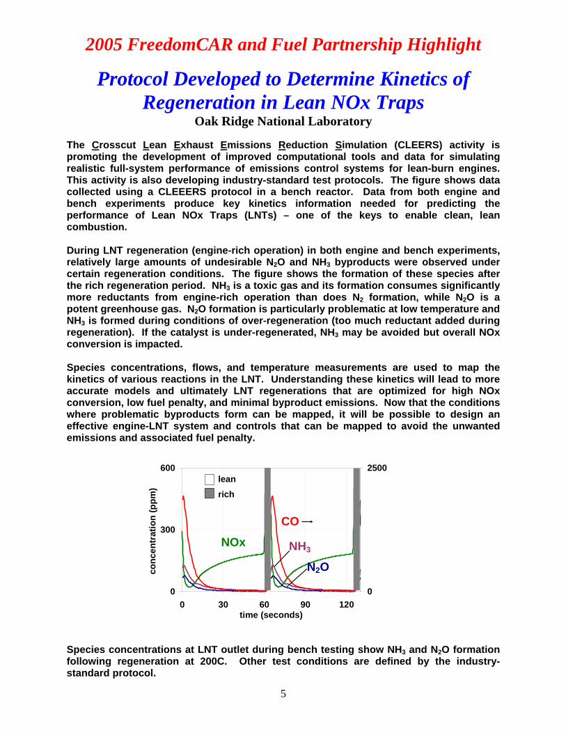
Oak Ridge National Laboratory The Crosscut Lean Exhaust Emissions Reduction Simulation (CLEERS) activity is promoting the development of improved computational tools and data for simulating realistic full-system performance of emissions control systems for lean-burn engines. This activity is also developing industry-standard test protocols. The figure shows data collected using a CLEEERS protocol in a bench reactor. Data from both engine and bench experiments produce key kinetics information needed for predicting the performance of Lean NOx Traps (LNTs) – one of the keys to enable clean, lean combustion. During LNT regeneration (engine-rich operation) in both engine and bench experiments, relatively large amounts of undesirable N2O and NH3 byproducts were observed under certain regeneration conditions. The figure shows the formation of these species after the rich regeneration period. NH3 is a toxic gas and its formation consumes significantly more reductants from engine-rich operation than does N2 formation, while N2O is a potent greenhouse gas. N2O formation is particularly problematic at low temperature and NH3 is formed during conditions of over-regeneration (too much reductant added during regeneration). If the catalyst is under-regenerated, NH3 may be avoided but overall NOx conversion is impacted. Species concentrations, flows, and temperature measurements are used to map the kinetics of various reactions in the LNT. Understanding these kinetics will lead to more accurate models and ultimately LNT regenerations that are optimized for high NOx conversion, low fuel penalty, and minimal byproduct emissions. Now that the conditions where problematic byproducts form can be mapped, it will be possible to design an effective engine-LNT system and controls that can be mapped to avoid the unwanted emissions and associated fuel penalty.
0
300
600
0 30 60 90 120time (seconds)
conc
entr
atio
n (p
pm)
0
2500
NOx
CO
NH3
N2O
richlean
Species concentrations at LNT outlet during bench testing show NH3 and N2O formation following regeneration at 200C. Other test conditions are defined by the industry-standard protocol.
5

2005 FreedomCAR and Fuel Partnership Highlight
Z-Source Inverter Reduces Cost and Complexity of Drive System in Fuel Cell Vehicles Michigan State University/Oak Ridge National Lab
Given the wide voltage range of fuel cells, a fuel cell vehicle traction drive system (motor and inverter) needs to be oversized to accommodate high speed and high power operation. Often a boost converter is used to alleviate this problem; however, the extra DC/DC stage and circuit complexity increases the cost and reduces the efficiency. A low cost and reliable Z-source inverter was developed as a solution for this application. A Z-source inverter combines the functionality of converter and inverter by using passive elements such as inductors and capacitors. The result is a more cost effective, smaller, and more efficient system. The intent of this work is to demonstrate the feasibility of the Z-source topology and its inherent size and cost advantages over conventional boost converter and inverter systems. The conventional DC/DC boost converter and PWM (Pulse Width Modulated) inverter configuration typically used in hybrid electric vehicles today is a two-stage power conversion, while the Z-source is a single-stage power conversion. The prototype built has several innovative design features, including a low cost and small size inductor to limit the current ripple, a DC circuit to reduce voltage overshoots, and current and voltage sensors for control and protection functions. These all result in fewer switches having lower current rated devices, thus reducing costs. The test results of 30kW (55kW peak) prototype Z-source inverter demonstrated high efficiency (greater than 97%), low cost (with lower device ratings), and wide constant speed power ratio reducing the need to oversize the system to meet vehicle requirements. A comparison of the Z-source inverter with the FreedomCAR goals is shown below.
Requirements FreedomCAR Goals
Inverter Prototype
Specific power @ peak load (kW/kg) >6* 4.7 Volumetric power density (kW/l) >6* 4.7 Efficiency, 10-100% speed, 20% rated torque (%)
>97 >97%
Peak power (kW) 55 80 Continuous power (kW) 30 30 Maximum current, rms (A) 300 300 Coolant inlet temperature (°C) 105 77
* Indicates goals for combined DC/DC and inverter system
Prototype Z-source inverter
6

2005 FreedomCAR and Fuel Partnership Highlight
Cost and Cell Performance Batteries for Hybrid Electric Vehicles
Compact Power Systems, Inc. / LG Chem Ltd. Cost and performance are major considerations for any automotive component, and batteries for Hybrid Electric Vehicles (HEVs) are no exception. Compact Power Systems, Inc. / LG Chem Ltd. (CPI / LGC) addressed both challenges in their new cell design as part of the Technology Development program. Although the cost shared portion of the program ended in August, 2005, testing of the program deliverables continues at Idaho National Laboratory (INL) and LGC. The CPI / LGC cell design, which is based on a LGC consumer cell, offers great potential to reduce cost because both the mechanical construction (flexible packaging) and the electrochemistry (Li ion with a Mn – spinel cathode material) are cheaper than alternatives. Although cells of this mechanical construction and/or electrochemistry are commonly used in consumer cell applications, their ability to meet the stringent FreedomCAR and Fuel Partnership performance goals has yet to be demonstrated. Cells being tested at LGC exceeded the Partnership goal of 300,000 cycles. Although CPI / LGC cells have yet to meet the other goals such as cost and low-temp performance, achievement of the 300,000-cycle goal is significant because few other developers have reached this level of performance.
200 300 400 500 600 700 800 9000
10
20
30
40
50
60
70
80
530Wh
334Wh
Rege
n Po
wer
(KW
, W X
BSF
)
Net Energy Removed (at C/1 discharge rate)
Dis
char
ge P
ower
(KW
, W X
BSF
)
0
10
20
30
40
50
60 BOL 300,000 cycles
CPI / LGC G4.0 cells: E vs. P after 300,000 cycles
(BOL = Beginning of Life; BSF = Battery Size Factor)
7

2005 FreedomCAR and Fuel Partnership Highlight
Low-Cost Lithium-Ion HEV Battery Separators Celgard, LLC
Reduction of separator cost by 50 to 75% has been identified as a key element in enabling lithium-ion HEV battery commercialization. This project was undertaken with the largest U.S. manufacturer of Li-Ion battery separators, Celgard LLC. The objective of this program was to develop a low-cost, dry-process lithium-ion battery separator manufacturing approach that would make a $1.00/m2 separator achievable, while simultaneously meeting FreedomCAR and Fuel Partnership requirements for electrical, mechanical, and thermal performance. Celgard has developed and demonstrated at pilot scale a polypropylene-based separator material with $1.00/m2 projected price for a 30 million square meter annual production level. This production level is approximately two times more than that required to support production of the Partnership's target of 100,000 hybrid vehicles per year, meaning that achievement of the price target requires other commercial applications (such as laptop computer or cell phone batteries) to use the same low-cost separator material. Because shut-down characteristics, whereby separator pores close at high temperatures to shut down ion transport and chemical reactions in the cell while maintaining separator dimensional integrity, are also desired in separators to enhance battery cell abuse tolerance, Celgard has also developed, under FreedomCAR contract, a tri-layer polypropylene/polyethylene separator with 135°C shut-down capability. This shut-down separator provides a 30°C buffer for cell shut-down below the 165°C melting temperature of a pure polypropylene separator. Celgard projects that this shut-down separator material could be sold for approximately $1.50/m2 at a 10 million square meter annual production rate, with a $1.00/m2 price breakpoint at approximately twice this annual production level. Significant equipment capitalization would be required to implement this alternative manufacturing approach, but Celgard's development effort has confirmed at pilot scale that alternative dry process manufacturing approaches are feasible for approaching the $1.00/m2 separator price target.
Low-cost polypropylene separator Low-cost tri-layer shut-down separator
Scanning electron microscope (SEM) photos of low-cost separator membrane surface.
8

2005 FreedomCAR and Fuel Partnership Highlight
Manufacturing and Cost Model Developed for Li-Ion Batteries
Johnson Controls
The cost of lithium ion batteries for use in hybrid vehicles is still significantly above FreedomCAR and Fuel Partnership goals. Previous projects significantly reduced costs for the active materials and separators but there is a need for further reductions. Developers have had difficulty in determining where to focus their efforts for these improvements. JCI has developed a manufacturing and warranty cost prediction model which quantifies the contribution to cost during all aspects of design and manufacture of a lithium ion battery. This model includes all aspects of the manufacturing process from the cell to full pack levels. The model also accounts for volume and throughput effects. The model shows that the primary areas for further cost reduction are in manufacturing and system design, specifically; coating rates, formation time and pack assembly. Through the use of this model JCI has successfully developed a roadmap to achieve a system cost of $35 per kW versus the present cost of $40 - $45 per kW. While this is still above the Partnership goal of $20 per kW, the model indicates that further reductions are possible with volume increase and possible introduction of more advanced manufacturing processes (reduction of humidity control cost or requirements). These issues will be addressed in a follow-up program.
QC/Engineering Maintenance
Office
Receiving
Shipping
Incoming
OvensOvens
OvensOvens
Cut and slit
Cut and slit
Dry Room winding
windingwindingwinding
Cell assembly
Mixing and Coating
Mod assem
bly -Fill
Material Storage
Formation
FormationlabBattery Assembly
Battery Assembly
MaterialsIncomingstorage
Finished Stock and Materials
320 ‘
250 ‘
QC/Engineering Maintenance
Office
Receiving
Shipping
Incoming
OvensOvens
OvensOvens
Cut and slit
Cut and slit
Dry Room winding
windingwindingwinding
Cell assembly
g and Coating
Mixin
Mod assem
bly -Fill
Material Storage
Formation
FormationlabBattery Assembly
Battery Assembly
MaterialsIncomingstorage
Finished Stock and Materials
320 ‘
250 ‘
Model-developed low-cost manufacturing plant layout
9

2005 FreedomCAR and Fuel Partnership Highlight
Viability of New High-Power Li-Ion Cell Chemistry Demonstrated
Argonne National Laboratory
Li2Mn2O4 spinel cathodes are very promising electrodes for use in Li-Ion HEV batteries because of their high power performance and low cost. However, cells using these electrodes exhibit insufficient calendar life, due to power loss associated with an increased resistance at the surface of the anode. Research results suggest dissolution and migration of Mn2+ to the anode, where it facilitates the interfacial resistance growth at the anode to cause cell power fade. Prior work at ANL showed that this phenomenon could be avoided with the use of Li4Ti5O12 (lithium titanate) anodes, which operate at a potential that is significantly different than conventional Li-ion anodes (lithiated graphite). However, lithium titanate possesses poor electronic conductivity and studies using conventional forms of lithium titanate indicate that they possess insufficient rate capability for use in high-power cells. This issue was resolved recently through ANL’s development of a nano-phase lithium titanate material. When this material is used in combination with Li2Mn2O4 spinel cathodes, the resultant cells possess extremely high-rate capabilities, as demonstrated by the full discharge profiles over a wide range of rates, as shown below. Early accelerated aging data at elevated temperature show this cell chemistry to be very stable. Another attractive characteristic of this cell chemistry is its superior tolerance to thermal abuse. These results are sufficiently promising to inspire industrial battery developers to initiate R&D efforts directed at developing this cell chemistry for HEV applications.
0.0
0.5
1.0
1.5
2.0
2.5
3.0
3.5
0 0.1 0.2 0.3 0.4 0.5 0.6 0Capacity, mAh
Voltag
e, V
1C5C10C
20C30C
40C50C
.7
Discharge profiles at various rates for cell with Li4Ti5O12 anode and Li2Mn2O4 spinel cathode
10

2005 FreedomCAR and Fuel Partnership Highlight
Achieving Higher Fuel Cell Catalyst Activity with Less Platinum
Brookhaven National Laboratory (BNL) The reduction of platinum (Pt) loadings in the air electrodes of fuel cells constitutes a primary means of reducing fuel cell cost to the levels required for mass-produced vehicles. BNL has produced and tested, on the laboratory scale, a series of innovative catalysts which exploit the observation that oxygen reduction proceeds more rapidly on a bare Pt surface than on a Pt surface covered with adsorbed oxygen species such as hydroxyl (OH). BNL has previously demonstrated that single layers of Pt atoms on some other materials, such as palladium (Pd) or gold-nickel alloys, have higher activities than the analogous all-Pt catalysts. The graph below shows a further enhancement of activity when atoms of another noble metal, such as ruthenium (Ru) or iridium (Ir), are substituted into the Pt monolayer. These other noble metals (M in the diagram below) have a higher affinity for hydroxyl than does Pt. The hydroxyls on the M sites (light-colored dots) repel OH from the adjacent Pt sites, and the resulting bare Pt sites give higher fuel cell activity. While these experiments were performed on idealized surfaces of large single crystals, other BNL monolayer catalysts have shown similar activity enhancements when tested in nanoparticle form in fuel cells. Such control of the composition and structure of the top-most atomic layers of catalyst particles gives hope of achieving the four-fold increase in mass activity vs. standard Pt/C catalysts needed to reach automotive catalyst cost targets.
Incr
easi
ng A
ctiv
ity
0 20 40 60 80 100
10
20
30
40
50(IrxPt1-x)ML / Pd (111)
(RuxPt1-x)ML / Pd (111)
Pt molar percentage %020406080100
-j k/ mAc
m-2 a
t 0.8
0V R
HE
M (Ru or Ir) molar percentage %
Pd
M
Pt
OH
O
Pd
M
Pt
OH
O
Sketch of the OH-OH or OH –O repulsion (PtOH coverage at 0.85V is ~1/2)
11
Mixed-metal platinum monolayer electrocatalysts
2005 FreedomCAR and Fuel Partnership Highlight
Dynamic Model of Fuel Cell Startup from Subfreezing Conditions
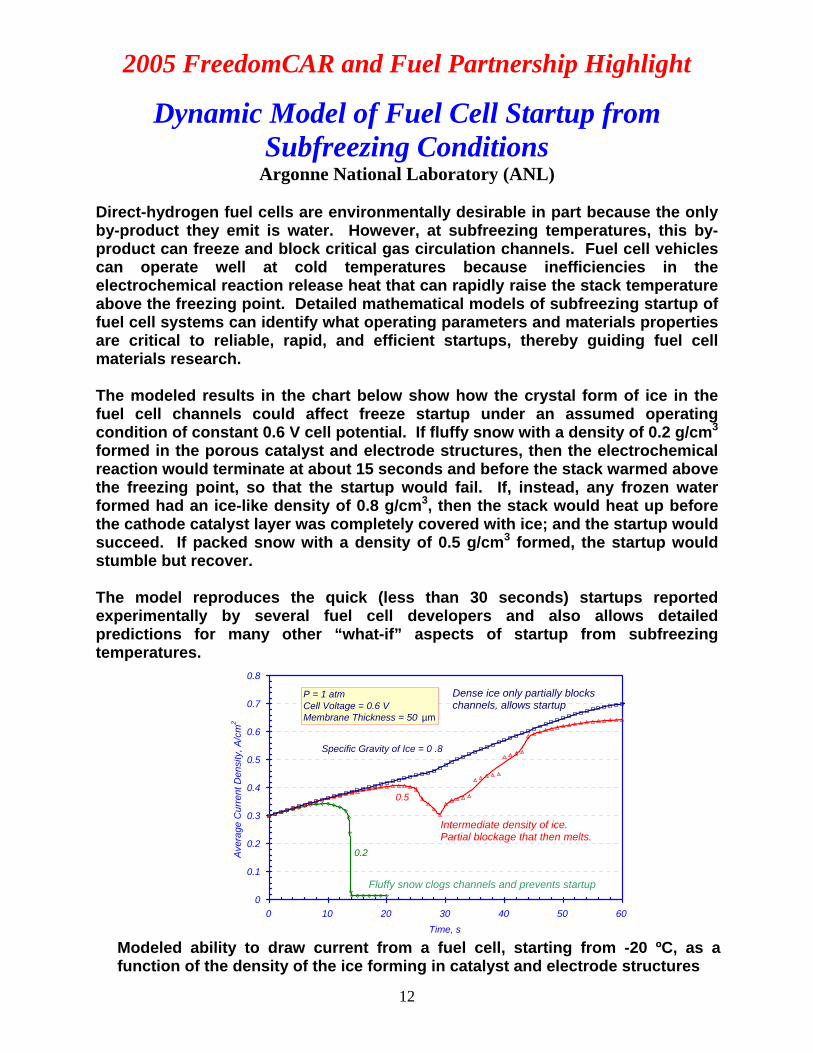
Argonne National Laboratory (ANL) Direct-hydrogen fuel cells are environmentally desirable in part because the only by-product they emit is water. However, at subfreezing temperatures, this by-product can freeze and block critical gas circulation channels. Fuel cell vehicles can operate well at cold temperatures because inefficiencies in the electrochemical reaction release heat that can rapidly raise the stack temperature above the freezing point. Detailed mathematical models of subfreezing startup of fuel cell systems can identify what operating parameters and materials properties are critical to reliable, rapid, and efficient startups, thereby guiding fuel cell materials research. The modeled results in the chart below show how the crystal form of ice in the fuel cell channels could affect freeze startup under an assumed operating condition of constant 0.6 V cell potential. If fluffy snow with a density of 0.2 g/cm3 formed in the porous catalyst and electrode structures, then the electrochemical reaction would terminate at about 15 seconds and before the stack warmed above the freezing point, so that the startup would fail. If, instead, any frozen water formed had an ice-like density of 0.8 g/cm3, then the stack would heat up before the cathode catalyst layer was completely covered with ice; and the startup would succeed. If packed snow with a density of 0.5 g/cm3 formed, the startup would stumble but recover. The model reproduces the quick (less than 30 seconds) startups reported experimentally by several fuel cell developers and also allows detailed predictions for many other “what-if” aspects of startup from subfreezing temperatures.
Intermediate density of ice. Partial blockage that then melts.
0
0.1
0.2
0.3
0.4
0.5
0.6
0.7
0.8
0 10 20 30 40 50 60Time, s
Ave
rage
Cur
rent
Den
sity
, A/c
m2
P = 1 atm Cell Voltage = 0.6 VMembrane Thickness = 50 µm
0.5
0.2
Specific Gravity of Ice = 0 .8
Dense ice only partially blocks channels, allows startup
Fluffy snow clogs channels and prevents startup
Modeled ability to draw current from a fuel cell, starting from -20 ºC, as a function of the density of the ice forming in catalyst and electrode structures
12

2005 FreedomCAR and Fuel Partnership Highlight
Effects of Subfreezing Temperatures on Fuel Cells Los Alamos National Laboratory (LANL)
Because the pressure exerted by freezing water is capable of splitting rocks, concerns have arisen regarding whether freeze-thaw effects would also be destructive to fuel cells. One of the few published papers on this subject showed a major loss of performance in a fuel cell after only four freeze-thaw cycles from −10 ºC to +80 ºC. LANL ran similar experiments (but on different fuel cells) and showed no degradation of fuel cell performance after 30 cycles from −5 ºC to +80 ºC (Figure 1). A similar lack of degradation was seen in tests with lower limits of −10, −20, −30, and −40 ºC. Only when the cell was frozen quicker and at a substantially lower temperature of −80 ºC, was significant degradation of fuel cell performance observed (Figure 2); scanning electron microscopy pointed to delamination of the catalyst layer from the membrane as the cause of this degradation. The dependence of the degradation on the lower temperature limit and decreased cooling rates suggests that extreme conditions were required to create the observed delamination, and that freeze-thaw cycling over tens of cycles under less aggressive conditions can be tolerated with no change in performance. Freeze effects are highly specific to particular cell designs and operating conditions. LANL also organized a freeze workshop that revealed sufficient details about the status of freeze technology from the fuel cell developers to set the context for productive fundamental research in this area.
13
Current density (A/cm2)
0.0 0.2 0.4 0.6 0.8 1.0 1.2
Cel
l pot
entia
l (V)
0.0
0.2
0.4
0.6
0.8
1.0
Current density (A/cm2)
0.0 0.2 0.4 0.6 0.8 1.0 1.2
Cel
l pot
entia
l (V)
0.0
0.2
0.4
0.6
0.8
1.0
2
HFR
( Ω c
m2 )
0.00
0.05
0.10
initialafter 1 cycleafter 3 cycleafter 5 cycleafter 7 cycleafter 9 cycle
-80 to 80oC cycle-51.2
HFR
( Ω c
m2 )
0.00
0.05
0.10
initialafter 10 cycleafter 20 cycleafter 30 cycle
to 80oC cycle1.
Figure 2: Fuel cell degradation
with -80 °C to 80 °C cycling
Figure 1: Fuel cell degradation with -5 °C to 80 °C cycling

2005 FreedomCAR and Fuel Partnership Highlight
Fundamental Mechanisms Tied to Fuel Cell Durability Issues
Los Alamos National Laboratory (LANL) The durability of polymer electrolyte membrane (PEM) fuel cells must be improved to meet the target operating life of more than 5,000 hours operating life under real automotive driving conditions. Operating under constant load, PEM fuel cell stacks have already performed well for longer than 12,000 hours (United Technologies); but stack lives in vehicles to date are much shorter. Therefore, in order to enable the development of adequately durable materials and designs, the specific aspects of automotive operation that are particularly stressful to fuel cells must be identified. LANL has investigated the effects on durability of a wide range of operating parameters, alone and in combination. The laboratory has previously shown that cycling the cathode between low and high potentials, which occurs during high/low power and shutdown/startup cycles, has a major effect in causing the initial small platinum particles of the cathode catalyst to grow into larger particles with smaller active surface area. Such particle growth is a major mode of performance degradation in fuel cells. The chart below shows that the fuel cell’s relative humidity also has a profound effect on the growth of catalyst particles during potential cycling. Wetter conditions lead to greater particle growth and more heavily degraded fuel cell performance. Fundamental studies such as these guide the development of materials and operating strategies for improved durability.
Bet
ter d
urab
ility
Effect of relative humidity of platinum particle size during fuel cell stack cycling
14

2005 FreedomCAR and Fuel Partnership Highlight
Improved Facilities for Imaging Water in Operating Fuel Cells
National Institute for Standards and Technology (NIST) It is frequently said that fuel cells are reliable because they contain no moving parts. However, the water produced by the electrochemical reaction of hydrogen and oxygen often produces droplets that move through the gas channels, causing temporary alterations of gas flow. Control of the way that “moving part” water leaves the fuel cell is critical to reliable and durable operation of these advanced power systems. Neutrons produced by a research nuclear reactor are uniquely suited to image water in fuel cells because, unlike most probes, they interact very strongly with the hydrogen atoms in water. NIST has developed neutron imaging techniques that can peer inside the cell while it is running, which has led to an improved understanding of just where and why water accumulates in fuel cells. The facility has generated both published scientific papers and significant proprietary research leading to improved fuel cell designs. During the past year, this national facility has significantly augmented its capabilities. A new, more intense beam line has been built and allows a larger section of the fuel cell to be imaged at one time (see figure). The temporal and spatial resolution of images has been improved, and equipment enabling operation of larger fuel cells under more realistic conditions has been installed. These changes will further increase the value of this national technical resource.
Schematic of the new neutron imaging facility that will provide enhanced capabilities for in-situ imaging and testing of fuel cells.
15

2005 FreedomCAR and Fuel Partnership Highlight
Membranes Resistant to Mechanical and Chemical Degradation
DuPont / UTCFC / UTRC Fuel cells in automotive applications must operate well for over 5,000 hours (FreedomCAR and Fuel Partnership goal) under widely varying load conditions and with frequent shutdowns and startups. Two modes of decay that predominate in polymer electrolyte membranes are (1) chemical attack by oxygen-based radicals and (2) physical degradation as a result of mechanical stresses such as those induced by the cyclic nature of automotive applications.
Identifying the mechanisms of membrane degradation is critical to the development of more durable fuel cells. DuPont and United Technologies have identified both chemical and mechanical modes of degradation and have demonstrated a coupling between the two modes. With this knowledge in hand, DuPont is developing a perfluorosulfonic acid (PFSA) polymer that demonstrates increased resistance to chemical attack. This stabilized polymer has been optimized and combined with novel composite membrane structures, designed to increase mechanical strength and improve dimensional stability. These new membranes show extended life in accelerated tests. To give adequate ionic conductivity for fuel cell operation, present-day membranes must absorb water from inlet gases and/or from the water produced by the cathode reaction of the fuel cell. As water is absorbed, the membrane volume swells. The water content in the membrane also changes during load and start-stop cycles such as those found in automotive applications. These cycles produce stresses that can lead to cracks and pinholes, which can accelerate the chemical attack from peroxide radicals produced in the fuel cell. The graph below shows that in accelerated tests, reducing the percentage of swelling by reformulating the membrane, reduces the degradation rate (presumably due to a reduction of the swelling stresses). Such work points a way toward membranes with the durability required for automotive use.
Bet
ter D
urab
ility
Effect of membrane swelling on fuel cell degradation (The data are for seven different membrane formulations)
16

2005 FreedomCAR and Fuel Partnership Highlight
Microstructural Characterization of Fuel Cell Membrane-Electrode Assemblies
Oak Ridge National Laboratory (ORNL) The most effective way to reduce fuel cell cost is to get more power out of a given-sized fuel cell. To do so requires improved electrode-layer structures that more readily allow hydrogen and air to reach the catalysts and the by-product, water, to drain away quickly. Catalyst layers contain platinum (Pt) for catalyst activity, carbon for electrical conductivity, ion-conducting polymer (ionomer) for ion pathways to complete the circuit, and open pores for transport of reactants and products. There is a critical need to develop methods to visualize, on the nanoscale, which kinds of electrode-layer structures produce good and bad electrode behavior. ORNL has developed methods to apply transmission electron microscopy to the developing nanotechnology of fuel cell electrode layers. The very high resolution of the microscopy successfully images the particular structure of the carbon black support material. This imaging allows for differentiation between the areas of carbon support and areas of ionomer—something difficult to achieve by other means. The image below shows, in the upper left, a very small section of electrode with near-ideal structure, with Pt particles (gray dots) covering the carbon support, which is in turn covered with a thin layer of ionomer. The lower right region of the image shows Pt particles in a thick layer of ionomer, not in contact with carbon. These Pt particles are likely being wasted. Such nanoscale-level imaging is critical to advance the development of fuel cell technology.
ideal region
Microstructural characterization tools can be used to evaluate preparation methods that produce better catalytic structures.
17

2005 FreedomCAR and Fuel Partnership Highlight
Non-Platinum Cathode Catalyst Layer with Improved Mass Transport
Los Alamos National Laboratory (LANL) Reducing the level of platinum (Pt) in cathode catalysts is the most probable pathway for lowering fuel cell costs to a level acceptable for automotive applications. Catalysts without noble metals (such as Pt) would provide additional economic advantages, and higher masses of such catalysts could be used in the fuel cell. Increasing the electrode layer beyond the ~0.01 mm thickness typically used in platinum-catalyzed fuel cells causes a significant loss of power, however, by lowering air supply to the reactive sites of the catalyst. The figure below shows the air-electrode behavior of equal loadings (2 mg/cm2, i.e., five times the normal Pt loading) of Pt and non-Pt (cobalt-based) catalysts. While the non-Pt catalyst still shows much lower activity than the Pt catalyst does, it does not show the rapid tailing-off of potential at higher current densities (this fall-off is typically seen for such catalysts as they run out of air). Good air supply to the electrode is maintained despite a thickness estimated at 10 times that of a normal fuel cell catalyst layer. This behavior was obtained through a novel catalyst preparation method developed in collaboration with the University of New Mexico. The catalyst precursor was supported on silica, which was removed via etching at the end of the catalyst synthesis process. The removal of silica resulted in a self-supported catalyst of well-defined pore structure. This catalyst was then used for making the cathode with superior mass transfer properties. Achieving good mass transfer through a very thick catalyst layer is one of the requirements for using non-Pt cathode catalysts. Before non-Pt catalysts can be considered realistic competitors to Pt, a higher activity per active site and significantly improved durability against automotive cycling must be demonstrated.
high
er a
ctiv
ity
Air-electrode behavior of platinum (Pt) and non-platinum (CoTPP) catalysts 18

2005 FreedomCAR and Fuel Partnership Highlight
Reclaiming/Recycling of Used Platinum Membrane-Electrode Assemblies
Ion Power and Engelhard Economic extraction of primary platinum (Pt) to meet anticipated demand for proton-exchange membrane (PEM) fuel cells will depend upon continued investment in mining technology. Recycling of transportation catalysts will play a critical role in the sustainable supply of Pt. The fluoropolymers comprising the membranes and part of the electrodes in most fuel cells must be disposed of in a way that does not emit hydrofluoric acid as occurs with conventional combustion processes, while also permitting the Pt to be economically recovered. Membrane materials are also sufficiently expensive that some form of reuse could have economic benefits. Therefore, methods are being investigated to recycle or remanufacture used membrane-electrode assemblies (MEAs) from fuel cells. Ion Power has dissolved the fluoropolymers from used MEAs and reprocessed them into new membranes from which new MEAs were made. The chart below shows that an MEA made from recovered fluoropolymer has delivered performance essentially equivalent to that of an MEA made from all-virgin materials. Ion Power has developed testing procedures to determine whether the catalysts (Pt particles on carbon) from used MEAs can be separated from the polymer and used in new MEAs. Engelhard is developing a more conventional Pt-recycling approach, in which Pt would be dissolved off of used MEAs and then purified for use in any application needing Pt. Engelhard has developed several processes that minimize or eliminate emissions of hydrofluoric acid. They have also developed a process to recover the fluoropolymer, though they propose less critical uses, rather than demanding fuel cell applications, for the recovered polymer. Pt recovery from fuel cells appears to be feasible; costs remain to be determined.
0.4
0.5
0.6
0.7
0.8
0.9
1.0
0.0 0.1 0.2 0.3 0.4 0.5 0.6 0.7 0.8 0.9 1.0Current Density, A/cm^2
Cel
l Vol
tage
, Vol
ts
S ingle Cell Made with 1 m il thick New NAFION® MEA# 359 @ 101 hrs on test
Single Cell Made with 1 m il thick Recycled / Re-Manufactured End-of-Life NAFION® MEA# 406 @ 27 hrs on test
Cell: 60 CDry Hydrogen, 1 ATM, 1.2 x Dry Air, 1 ATM, 2.5 x
Comparison of fuel cell performance with recycled NAFION® from end-of-life system and that with virgin NAFION®
19

2005 FreedomCAR and Fuel Partnership Highlight
State-of-the-Art Cathode Mass Activity in a Durable Electrode Structure
3M A key to low-cost fuel cells is an increase in mass activity of the cathode catalyst, that is, an increase in the current obtainable per milligram of precious metal used at a given voltage. However, high initial activity alone is not enough. The high performance must remain stable despite load cycles that tend to cause catalyst particles to grow (which reduces the active surface area) and despite frequent shutdown/startup cycles (that corrode the support structure for the catalyst). 3M previously demonstrated extraordinarily durable membrane electrode assemblies (MEAs) made with an unusual catalyst structure: a continuous platinum (Pt) film deposited over a nanostructured thin film (NSTF) of crystalline, organic whiskers. The mass activities of these pure Pt-coated whisker-supported catalysts were equivalent to the ~0.1A/mgPt (@900mV) levels seen in Pt-only catalysts on conventional carbon black supports, not the ~2.5-fold higher activities seen in Pt alloys on carbon blacks. The figure shows that 3M has now achieved state-of-the-art Pt-alloy mass activities (0.26A/mgPt) in their exceptionally durable whisker electrode structure. A combination of new alloy compositions and refined supports has led to this unique combination of durability and mass activity. Continued work is needed to obtain the still-higher activities (~0.4A/mgPt) needed for full commercialization, to define and widen the range of operating conditions that these special catalysts can tolerate, and to address other issues of MEA durability.
0.00
0.05
0.10
0.15
0.20
0.25
0.30
0.35
0.40
Pure Pt
mg-Pt/cm2
= 0.15
0.150.06
0.15
0.06mg-Pt/cm2 = 0.08
PtCxDx686A
PtCxDx686A
PtCyDy683C
PtCyDy683A
PtCD*683C
Mas
s A
ctiv
ity, i
m(0
.9V)
(A/m
g Pt)
Catalyst Sample (Loading, Composition, Whisker)
Mass Activity, A/mg @ 900mV
Improved activity of alloyed catalysts compared to that of pure platinum
20

2005 FreedomCAR and Fuel Partnership Highlight
21
Hydrogen Storage Systems Engineering Facility Enables Measurement and Analysis
Argonne National Laboratory, TIAX, UTRC and Sandia National Laboratory Storing enough hydrogen on board a fuel cell vehicle to achieve a driving range of more than 300 miles is a significant technical challenge. Initial goals include building a storage system with this capability within a volume comparable to that of current gasoline fuel systems and with the hydrogen comprising 6% or more of the total system weight (2010 target). A number of high hydrogen capacity materials with potential to meet these goals are currently being investigated. Each class of materials would likely have a very different configuration when used in a vehicular fuel tank and it is important to know what their actual performance would be as part of a fuel system. Consequently, an important deliverable will be storage system prototypes to determine overall system performance as opposed to only material-level performance. Sandia National Laboratory has built a facility, shown below, to measure hydride material engineering properties such as thermal conductivity and expansion. Sandia has used these data to model heat and mass flow in hydride beds. Argonne National Laboratory has used engineering models to estimate the performance of storage technologies at an early stage of their development. Some preliminary results suggest what a carbon adsorption-based fuel system might look like in terms of volume, weight and capacity. TIAX has used a similar approach to benchmark a complex hydride system built by UTRC and has made a detailed cost break-out, seen in the bar graph, of the total cost for the different subsystems and components. These system analysis studies have provided important information on the performance expected from materials currently under study. They have also provided insight into subsystem and component characteristics needed to minimize system weight, volume and cost.
Sandia National Labsengineering properties
facility
TIAX cost breakdown analysisof alanate storage system
Sandia National Labsengineering properties
facility
TIAX cost breakdown analysisof alanate storage system

2005 FreedomCAR and Fuel Partnership Highlight
Improved Hydrogen Release from High-Density Metal Hydride, AlH3
Brookhaven National Laboratory/Sandia National Laboratory Efficient on-board storage of hydrogen (H2) requires a system that: a) provides hydrogen at high-densities by volume and weight, b) allows removal of the H2 with modest energetic input, and c) uses a simple, low-cost method to recharge the material back to its original state. Aluminum hydride (AlH3) is potentially an attractive storage material due to its high density of hydrogen by weight and volume. The chemical formula contains a theoretical 10 wt.% of H2, and a theoretical density of hydrogen in the compound (148 g H2/L) that is more than double the density of liquid H2. However, despite the fact that this compound has been known for 60 years, several issues prevent its being a viable storage option. One of these obstacles is the slow rate of hydrogen release from AlH3. DOE researchers at Brookhaven and Sandia-Livermore National Laboratories have recently demonstrated two methods to improve the rate (or lower the temperatures) of H2 desorption from this material. They showed that ball-milling the material decreases the metal hydride particle size, lowering the temperature for H2 desorption by 25-50 °C. The research team also found that alkali metal hydrides, such as LiH, acted as "metallurgical stimulants" and enhanced desorption kinetics when added to AlH3. These additives provide an additional lowering of desorption temperatures by 40-50 °C. This research demonstrates the onset of hydrogen desorption below 125 °C, with H2 yields of 7-8 wt.% (based on material only) below 175 °C. In order to utilize AlH3 as an on-board storage technology, more research is still required. Of highest priority is developing a practical method to convert the spent Al powder back into AlH3. Additionally, further lowering the desorption temperature would be desirable to make the release of H2 compatible with the waste heat generated by a PEM fuel cell system(~80 °C). Finally, the infrastructure implications of a solid-state hydride storage option that is not rechargeable on-board the vehicle need to be explored.
(b)(a)
(a) AlH3 metal hydride particles and (b) H2 desorbed vs. temperature for AlH3 doped with LiH. The doped samples (yellow, blue, and red curves) show significantly lower temperatures of desorption than the undoped samples (black curve).
22

2005 FreedomCAR and Fuel Partnership Highlight
Nanostructured Scaffolds Improve Ammonia Borane Hydrogen Storage Characteristics
Pacific Northwest National Laboratory In order to meet challenging onboard hydrogen storage targets it is important to use materials with a high hydrogen storage capacity and low energy requirements - so that the hydrogen is easy to release. Ammonia borane, with the chemical formula NH3BH3, and total hydrogen content of about 18 wt.%, is an emerging candidate material. Unfortunately, it releases hydrogen slowly and it is very difficult to replace the hydrogen to re-form ammonia borane. Ammonia borane could rehydrogenate more readily if it were chemically or physically altered so that less heat is evolved when hydrogen is released. A team at Pacific Northwest National Labs (PNNL) has made significant progress in this direction by inserting ammonia borane into the pores of a nanoscale engineered material called a mesoporous scaffold. These silica-based scaffolds provide much improved properties of the ammonia borane: the thermodynamics are changed such that almost no heat is generated as hydrogen is released; the kinetics are improved such that hydrogen is released faster and at lower temperatures; and undesirable byproducts, such as borazine, are essentially eliminated. The scaffolds add weight, but a total hydrogen storage capacity of greater than 6% by weight (on a materials basis) was still achieved. The use of silica based scaffolds provides significant progress toward the application of ammonia borane as a storage material. Further progress, needed to achieve efficient rehydrogenation of ammonia borane, may be possible by altering the chemical composition of the scaffold. Future work will focus on tuning the interactions between ammonia borane and the scaffold to improve its thermodynamic properties and to minimize the mass and volume of the scaffold. Hydrogen is released
faster and at lower temperature when ammonia borane is in a scaffold.
Pure aminoborane
A microscope image of ammonia borane in a mesoporous scaffold
The amount of heat generated during hydrogen release is significantly lowered with the mesoporous scaffold.
23

2005 FreedomCAR and Fuel Partnership Highlight
24
Novel Liquid-Phase Hydrogen Carrier Air Products and Chemicals, Inc
Hydrogen storage is critical to the success of the overall hydrogen economy. Currently available storage technologies do not meet many of the requirements for commercially viable automobiles. Novel automotive on-board hydrogen storage systems must be simple, efficient and durable, with a high hydrogen density (6% H2 mass; 2010 system goal). Air Products and Chemicals, Inc (APCi) has demonstrated several novel liquid-based H2 carriers that can store H2 at ~ 5.5 to 7% by weight and 50-65g/L on a material level. One of the materials, for example, is n-ethylcarbazole. At 170-190 °C the fluid produces greater than 99.9% pure H2 from a catalytic dehydrogenation with a more than 95% yield. Preliminary testing recycled the fluid six times without significant loss in hydrogen carrying capacity or catalyst activity. A schematic is shown below. This storage material has two significant advantages over alternative methods: 1) The material is a low volatility organic liquid, with a viscosity similar to that of mineral oil. Liquids provide simplified and economical transportation of the fuel and enhanced packaging on the vehicle by allowing conformable tanks. The dehydrogenated waste product is similar in characteristics and has a slightly higher viscosity than the starting material. 2) The dehydrogenation process is endothermic and heat input is required to release the hydrogen. This provides a safety benefit on the vehicle to prevent unintended hydrogen releases and may also help to improve energy efficiency and reduce radiator sizes by using fuel cell waste heat if the desorption temperature is reduced to ~80 °C. Well-to-wheels efficiency may also be improved by capturing and reusing heat generated during the exothermic re-hydrogenation process. Future work will focus on improving the overall efficiency of the system by optimizing fluid and/or catalyst composition to further reduce the H2 release temperature. The Delivery Technical Team also plans to review DOE-funded research on systems/ engineering aspects of this technology.
Schematic of liquid-phase hydrogen carrier

2005 FreedomCAR and Fuel Partnership Highlight
Advanced Binder Control for Robust Stamping USCAR - USAMP
Significant weight savings can be achieved by the use of lightweight and high specific strength materials rather than mild steel. Such materials, however, are commonly less formable, and result in higher springback, than mild steel. The forming of lightweight materials requires innovative tooling and advanced controls. Traditional stamping uses rigid binders: these do not address local forming conditions and cannot respond to process variations that may lead to stamping inconsistencies or even failure. Advanced flexible binder load control systems, coupled with optimization and computer simulation and equipped with closed loop control, could improve manufacturing ability and the stamping robustness of lightweight materials. Such a system was built and used to successfully stamp liftgate panels from BH210 and DP500 steels, and A6111-T4 aluminum using the same set of tools (Figure 1). The tryout time using the system was considerably less than that using conventional methods of reworking the die (welding, grinding, polishing and testing). Splits and wrinkles in stamped panels could be remedied in only minutes rather than days by adjusting the tonnages of the appropriate cylinders. Prior efforts to make the liftgate from A6111-T4 using conventional methods were unsuccessful. Figure 2 shows the dramatic benefits of using closed loop control in eliminating wrinkles in a large steel pan. This technology is expected to reduce the time and lower the cost for fine tuning of stamping tools. Implementing this technology will have a significant impact on the US automotive and stamping industries and lead to increased use of lightweight materials in vehicles.
Figure 1: Liftgate panels made from two steels (BH210, DP500) and two aluminum (A6111-T4) batches (lower photo)
25
Figure 2: Steel Pan drawn without (upper photo) and with closed loop control (lower photo)

2005 FreedomCAR and Fuel Partnership Highlight
26
Cost of Wrought Magnesium Sheet Assessed Pacific Northwest National Laboratory
Magnesium has a specific stiffness comparable to that of materials like aluminum or steel but has a much lower mass density. Its high strength-to-mass ratio has led to an increasing global interest in the use of magnesium for structural components. A number of research activities are under way to develop approaches for producing magnesium sheet at the volume and cost levels demanded by automotive applications. The economics associated with some of these emerging yet promising technologies are unclear. As such, the Aluminum Consultants Group, in conjunction with Pacific Northwest National Laboratory, prepared a technical cost model for magnesium sheet production alternatives. In developing the cost model, options for producing magnesium sheet were identified and processing details studied. The model focuses on the two most commercially prominent continuous casting processes, twin belt casting and twin roll casting. The design and data used in the model are based largely on information and experience with aluminum continuous casting, with anticipated modifications required for magnesium sheet production. Supplemental information specific to magnesium continuous casting was obtained from the literature and solicited directly from organizations involved in each of the processes. The model focuses on three primary cost elements: metal, casting, and sheet rolling. For the continuous cast magnesium sheet model, two “base cases” were developed to provide a starting point for subsequent sensitivity analyses. These two base cases used the same inputs for the metal cost and rolling cost elements, with a difference in the casting costs. The projected production costs for twin roll and twin belt casting of 1.5-mm-thick magnesium sheet are $1.97 per pound and $2.43 per pound, respectively (not including profit or overhead costs). This compares to an industry quoted price, which includes profit and overhead, of $4.50 per pound for magnesium sheet produced by conventional ingot metallurgy methods.
Twin Roll
Metal Cost82%
Casting Cost8%
Rolling Cost10%
Twin Belt
Metal Cost67%
Casting Cost25%
Rolling Cost8%
$2.43 Total Cost/lb$1.97 Total Cost/lb
Percentage of Total Cost for Each Primary Cost Element

2005 FreedomCAR and Fuel Partnership Highlight
Durability-Driven Design Guidelines for Carbon-Fiber-Based Composite Systems
Oak Ridge National Laboratory Before composite structures that offer higher strength and lower mass can be widely used in automotive applications, their long-term durability must be assured. The Durability of Carbon-Fiber Composites project at the Oak Ridge National Laboratory was established to develop the means for providing this assurance. Experimentally-based, durability-driven design criteria and damage-tolerance assessment procedures have now been developed for representative carbon-fiber composite systems to assure the long-term (15 year) integrity of composite automotive structures. Durability issues considered include the potentially degrading effects of cyclic and sustained loads, exposures to automotive fluids, temperature extremes, and incidental impacts from such things as tool drops and kick-ups of roadway debris. The effect that these environmental stressors and loadings have on structural strength, stiffness, and dimensional stability has also been studied. As an example, one composite material recently investigated was a Poly Phenyl Sulfide (PPS) matrix symmetrically reinforced with 16-ply carbon-fiber unidirectional tape, [0/90/±45]2S. Primary activities associated with evaluation of this material addressed thermoplastic material characterization, baseline property determination, and conduct of experimental tests of durability as described above. A final report providing durability-driven design guidelines for this material will be released.
Fatigue test set-up to measure effect of automotive fluids on material properties
27

2005 FreedomCAR and Fuel Partnership Highlight
Feasibility of Low-Cost Titanium Process Established
Pacific Northwest National Laboratory One way to improve fuel economy in automobiles is to reduce the overall vehicle weight. However, it is important to do this in a way that does not compromise durability, driving performance, or safety, and that is economically viable. Direct replacement of steel with titanium can reduce component mass by up to 65%. At issue is the high cost of wrought and powder titanium on the open market, which has limited its use to niche applications in high-performance, low-production vehicles and demonstration models. A recent cost study was performed by Camanoe Associates in conjunction with the Pacific Northwest National Laboratory (PNNL). It concluded that the use of a low-cost titanium ore as the feedstock source in a continuous reduction process could drive down the cost of titanium sponge and powder sufficiently for such materials to be considered for application in standard automotive components. This continuous process used in conjunction with a low cost feedstock can produce powder at $2 per pound compared to about $4-$5 per pound for conventional elemental powder or titanium sponge. PNNL is currently leading a program to develop this low-cost titanium processing stream. Working with E. I. DuPont de Nemours and International Titanium Powder (ITP), PNNL has employed low-cost, ilmenite-derived titanium tetrachloride (of the type used for titanium dioxide paint pigment production) as the precursor in ITP’s Armstrong titanium synthesis process. The resulting titanium powders, while containing additional impurities (primarily tin and silicon), appear capable of meeting strength and ductility requirements for a wide range of automotive applications at significantly reduced cost.
Examples of powder-metallurgy titanium oil-pump gears made from low-cost titanium powder at PNNL
28

2005 FreedomCAR and Fuel Partnership Highlight
Structural Cast Magnesium Development USCAR - USAMP
The use of magnesium for selective automotive components provides structural capabilities at a fraction of the weight when compared to other metals. It has been claimed that potential weight savings of up to 15% are possible in theory for the average vehicle, with corresponding fuel savings of up to 10%. The “Structural Cast Magnesium Development” (SCMD) project focused on resolving critical issues that previously limited the large-scale application of magnesium castings in automotive components. The principal investigators were drawn from the National Laboratories and universities. The SCMD project is considered a dual path project with scientific activities developed to resolve technical issues and solutions validated with exhaustive vehicle testing. Project success was demonstrated by the following: • Significant scientific understanding of magnesium cast microstructure. • Development of cost model to define manufacturing cost factors. • Comprehensive database and design guidelines for CAE/Product engineers. • Improved processes to develop high integrity castings. • Corrosion studies and innovative fastener development for better corrosion
resistance. • Improved magnesium alloys and bolt load retention studies for sound joints. • Transfer of knowledge and lessons learned to industry through the publication of
a North America Automotive Magnesium Strategic Vision document. Major accomplishments include: 1) Completion of the above assignments to achieve the successful validation of the magnesium front engine cradle in a 2006 production vehicle. This resulted in a 34% weight savings compared to the 2005 production aluminum engine cradle. 2) Development of a magnesium strategic vision document to outline recommendations for the North American automotive magnesium industry through the year 2020. The document uses as a benchmark many of this project’s accomplishments. The success of the SCMD project is helping FreedomCAR achieve its fuel efficiency goals and is also stimulating other magnesium projects. The latter, identified in the Magnesium 2020 document, are currently being proposed in collaboration with the magnesium industries of North America, Canada and China.
Magnesium Front Engine Cradle 29

2005 FreedomCAR and Fuel Partnership Highlight
AVTA Collects Hybrid Vehicle Performance Idaho National Laboratory
Life-cycle performance and durability of hybrid electric vehicles (HEVs) and their batteries can now be measured at DOE’s Advanced Vehicle Testing Activity (AVTA) and its testing partner, Electric Transportation Applications. HEVs are tested in fleets, accumulating 160,000 test miles per HEV within 3 years (accelerated reliability testing). In addition to fuel economy testing, all maintenance and repair events and costs are documented, allowing life-cycle cost analysis. Each HEV model is also tested in controlled environments (dynamometers and test tracks) to establish baseline performance.
The 28 HEVs in the program include six Honda Insights, six Gen I Toyota Priuses, four Honda Civics, two Gen II Toyota Priuses, two GM Silverados (one 2-WD and one 4-WD), two Honda Accords, two Ford Escapes (one 2-WD and one 4-WD), two Lexus RX400hs, and two Toyota Highlanders. (The AVTA is also testing hydrogen internal combustion engine vehicles).
After 1.5 million accelerated reliability test miles, the HEV fuel efficiencies range from 18.1 mpg to 45.2 mpg, depending on hybrid configuration and vehicle size. During the baseline performance testing, the SAE J1634 drive cycle test is conducted once with the air conditioning (AC) on and once with the AC off. The fuel economy was 15 to 27% lower (21% average) when the J1634 test was run with the AC on (see graph).
End-of-life battery (static capacity and Hybrid Pulse Power tests) and fuel economy tests (SAE J1634 again with the AC on and off) are conducted on each HEV that reaches 160,000 miles. The battery capacities faded 32% for the two Civics, 15% for the two Insights and 61% for the two Gen I Priuses at 160,000 miles.
The testing results and life-cycle costs are provided to the Argonne and Oak Ridge National Laboratories, the National Renewable Energy Laboratory, and to industry groups as benchmark data for FreedomCAR powertrain development and cost models, and to research and development programs.
Accelerated Reliability and Baseline Performance (with air on and off) Fuel Economy
0
5
10
15
20
25
30
35
40
45
50
55
60
65
Civic Insight Gen I Prius Gen II Prius Accord Silverado Escape Lexus Highlander
Mile
s pe
r Gal
lon
Accelerated Reliability SAE J1634 Drive Cycle - Air On SAE J1634 Drive Cycle - Air Off
Accelerated Reliability and Baseline Performance Fuel Economy
30

2005 FreedomCAR and Fuel Partnership Highlight
31
Benchmarking Advanced HEV Technology with 4WD Dynamometer Facility
Argonne National Laboratory
Hybrid electric vehicle (HEV) technology is advancing at a rapid pace, increasing the need for accurate evaluation. The FreedomCAR and Fuel Technical Teams are working to advance research in various subsystems and the Advanced Powertrain Research Facility (APRF) is uniquely suited to test a wide array of advanced technologies. In order to perform these tasks efficiently, it is vital to have proper benchmarking data and comprehensive measurements from the most recent commercially available technology.
Testing was conducted on the 2005 Accord HEV, an ISA hybrid 6-cylinder with 3-cylinder deactivation. The interaction between cylinder deactivation and hybrid operation was characterized. The vehicle is remarkably smooth when changing modes due to the management of motor torque and cylinder deactivation.
A major accomplishment in the APRF was a study of the fuel economy sensitivity of conventional and hybrid vehicles. The results showed performance trends for hybrids and explained the underlying causes for the significant fuel economy shortfalls observed in use with hybrid vehicles. The controlling input to quantify sensitivity was a scaling factor on the EPA drive cycles. The resulting range of results illustrates why vehicles with over-sized engines appear to be very robust with respect to fuel economy. Hybrid vehicles have high efficiency and can not improve at the same rate as conventional vehicles, thus hybrid fuel economy appears to be more sensitive to aggressive driving.
Urban Drive Cycle
0
10
20
30
40
50
60
70
80
0.6 0.8 1.0 1.2 1.4 1.6Scaling Factor
Fuel
Eco
nom
y [m
pg]
Insight
Prius
Echo
Focus
Escape
Jaguar
-
0.05
0.10
0.15
0.20
0.25
0.30
0.35
0.40
0.45
0.8xUDDS 1.0xUDDS 1.2xUDDS 1.4xUDDS
Cyc
le P
ower
trai
n Ef
ficie
ncy
PRIUS
INSIGHT
ECHO
FOCUS
ESCAPE
XJ8
Sensitivity of measured fuel economy and performance of HEVs to EPA drive cycles

2005 FreedomCAR and Fuel Partnership Highlight
32
H2A Cost Modeling Tool Argonne National Laboratory, National Renewable Laboratory, Pacific
Northwest National Laboratory, University of California (Davis), Directed Technologies, Inc., Parsons Corporation,
Technology Insights and TIAX
In 2005, the US Department of Energy (DOE) completed and issued the Hydrogen Analysis (H2A) tool for consistently analyzing and reporting the cost of hydrogen production via a range of technologies. Beyond this base capability, the model will also streamline the costs analysis process for complete production for the analysis of various pathways. The effort to develop this tool brought DOE, national laboratories, universities and industry together to enable more consistent, transparent and comparative cost estimates for producing hydrogen. The H2A tool helps researchers calculate production cost on a common basis by standardizing the economic parameters and the financial approach. Key elements include: internal rate of return (IRR), construction time, taxes, depreciation, inflation, projected feedstock prices and discounted cash flow methodology. The H2A tool will be used within DOE to estimate the cost of hydrogen production from a variety of technology options and will be available to the public in order to facilitate commonality in production cost analysis. The H2A tool resulted from collaboration between the Department of Energy, national laboratories (National Renewable Energy Laboratory, Argonne National Laboratory, Pacific Northwest National Laboratory), universities (University of California at Davis), and industry (Technology Insights, Parsons Corporation, Directed Technologies, Inc., TIAX). Expert feedback on the H2A model assumptions, expected results, and sensitivity analysis parameters was also provided to DOE by key industrial collaborators, which included members of the energy companies in the FreedomCAR and Fuel Partnership.

2005 FreedomCAR and Fuel Partnership Highlight
H2A Hydrogen Delivery Models Argonne National Laboratory, National Renewable Energy Laboratory,
Pacific Northwest National Laboratory Low cost and energy efficient delivery of hydrogen from central production facilities is an essential enabler for widespread use of hydrogen fuel cell vehicles. There are a number of options for hydrogen delivery including gaseous hydrogen delivery in pipelines or high pressure tube trailers, liquefaction and transport of liquid hydrogen in cryogenic trucks, and the use of novel carriers such as metal or liquid hydrides. Full infrastructure costs and energy efficiencies are a complex function of the technology and the geographic layout of the infrastructure. In order to guide the research needed, one must fully understand the major factors that drive the cost and efficiency of hydrogen delivery. A team of researchers from the Argonne, National Renewable Energy, and Pacific Northwest National Laboratories was charged with developing models that could comprehensively analyze hydrogen delivery infrastructure costs and performance. Two delivery models have been developed: the Hydrogen Analysis (H2A) Delivery Components Model and the Scenario Model. The Components Model analyzes the cost contribution of the individual components of the infrastructure. The Scenario Model uses the Components Model, allows the user to specify a geographic scenario, and analyses the full delivery infrastructure cost contribution to the cost of hydrogen. An example scenario would be delivery to a city of a certain size, with a given fuel cell vehicle market penetration, and with a central hydrogen plant located a given distance from the city (see figure below). Such delivery models are proving invaluable to help guide the hydrogen delivery research needed to reduce the costs and improve the energy efficiency of hydrogen delivery.
Market Penetration %) (
Pipeline Liq H2
GH2 Tube Trailer
100 90 80 70 60 50 40 30 2010
City of 250,000 people, Hydrogen Plant: 62 miles from c ty gate
$0.0 0
$2.0 $4.0 $6.0 $8.0
$10.0 $12.0 $14.0 $16.0 $18.0 $20.0 $22.0 $24.0
i
33 Urban hydrogen delivery cost based on scenario model

2005 FreedomCAR and Fuel Partnership Highlight
34
Natural Gas Distributed Reforming Technology Assessment by Independent Review Panel
Hydrogen Production Technical Team / National Renewable Energy Laboratory
The Department of Energy’s (DOE) Hydrogen Program 2005 technology-specific research goal for the cost of natural gas distributed reforming is $3.00/gasoline gallon equivalent (gge). The DOE Hydrogen Program has nine projects currently working to achieve this research goal but, as noted by the reviewers in the 2005 Annual Merit Review Report as well as the Hydrogen Production Technical Team (HPTT) members, there is a lack of consistent cost data for natural gas distributed reforming. In response, the HPTT organized a series of project reviews to look at the current state-of-technology for producing hydrogen by reforming natural gas at the end-use point. The HPTT approach is evaluating cost and energy efficiency using the H2A model assumptions as a common base. The H2A model provides critical design and operation assumptions such as common capacity utilization and capital investment rate of return factors. The HPTT, as part of the review of the current status of natural gas distributed reforming, visited and evaluated the following DOE sponsored projects: National Renewable Energy Laboratory’s (NREL) biomass reformer, General Electric’s autothermal cyclic reformer, H2Gen’s hydrogen generator, and Gas Technology Institute’s hydrogen fueling station. The HPTT also reviewed Praxair’s hydrogen production platform project via web cast and conference call. As part of the project reviews, the HPTT gave feedback to DOE and gathered information to assist in the evaluation of the current status of the Research Goal for the cost of natural gas distributed reforming systems. The HPTT continues to collect data through project reviews and will be a data source for the Independent Review Panel. Each member of the HPTT will be available to respond to questions asked by the Independent Review Panel about various reformer system technologies they have expertise in. NREL is responsible for setting up and leading the Independent Review Panel in the evaluation of the current state-of-technology of producing hydrogen by distributed reforming of natural gas. This independent review will use data and information obtained by the HPTT, technical input provided by the public through the Federal Register, and literature searches performed by the Independent Review Panel. The Panel will complete a final report addressing every aspect of distributed natural gas reformed hydrogen fuel costs including initial capital investments, installation cost, fixed costs, and variable costs. These combined efforts will be a major achievement in measuring the current performance of natural gas distributed reforming for hydrogen production. The DOE and industry will be in a better position to identify activities necessary to achieve the Partnership’s 2015 Research Goal: $2-3/gge, produced and delivered to the consumer independent of pathway.
Praxair’s Low-Cost Hydrogen Platform

2005 FreedomCAR and Fuel Partnership Highlight
35
Outcomes Maps Development Hydrogen Production Technical Team
The Hydrogen Production Technical Team (HPTT) is chartered with working on pre-competitive, high risk research in hydrogen production technologies, and identifying the most significant technical challenges and most promising technological solutions. As part of its charter, the HPTT is working on data/technology gap identification and analysis, review of study results, and analysis of research & demonstration (R&D) goals, targets, and milestones. The HPTT reviews the viability of current and future hydrogen production technologies on a continuing basis. In particular the HPTT is evaluating: distributed reforming of natural gas and renewable liquids, water electrolysis, biomass reforming, high-temperature solar thermochemical, biological, and photolytic technologies. The HPTT adopted a tool called “Outcomes Maps” to define the different hydrogen production technology development needs and assist in the identification and analysis of data/technology gaps. The first outcomes maps were developed for the near-term production technologies, which include distributed reforming of natural gas and renewable liquids, as well as water electrolysis, to produce hydrogen. The outcomes maps, as seen in the figure below, are a series of related goals or “outcomes” leading to aggressive technology-specific Research Goals for 2010 and 2015 of the Partnership Plan. The outcomes were color coded to represent what kind of organization (government, industry, and suppliers) should be working on an outcome, and what level of risk and impact each outcome must overcome. For example, blue is government/energy industry and is high risk, high impact; green is industrial technology developers and high impact, short development time; red is low interest and low impact; yellow is supplier and is short term, low importance. The HPTT has identified all outcomes for the specific technology targets and links the existing Department of Energy (DOE) sponsored R&D project(s) to the correlating outcomes. This approach allows the HPTT to assess the work being done on each outcome and to ensure that the right organizations are working toward the outcomes necessary to achieve the 2015 Partnership Plan Goal for hydrogen fuel cost: $2-3/gge, produced and delivered to the consumer independent of pathway. The technical team completed the technology outcomes this past fall and will continuously update them to assess achievements and future needs.
Natural gas distributed reforming Outcomes Map

2005 FreedomCAR and Fuel Partnership Highlight
36
Technical Reference for Hydrogen Compatibility of Engineering Materials Sandia National Laboratories
The Hydrogen Compatible Materials project is generating information on materials and methods of construction, supporting the development of new codes and standards to ensure the safe handling and transport of hydrogen. The Technical Reference for Hydrogen Compatibility of Materials is the focal point of the effort and there are two parallel paths for compiling the Technical Reference: 1) data collection and validation from existing peer-reviewed journals and reports, and 2) a materials testing program to generate data of particular interest to the codes and standards community. The Technical Reference is a publicly available, web-based document accessible at http://www.ca.sandia.gov/matlsTechRef/. Nine chapters are currently available for download -- six chapters on austenitic steels (used for small-volume components and tubing) and three chapters on ferritic alloy steels (used in pressure vessels). Several more chapters are in progress on ferritic carbon steels (pipelines), aluminum alloys (pressure vessels and internal combustion engine components), and copper alloys (seals). The document provides a comprehensive summary of existing materials compatibility data for each specific alloy with high-pressure hydrogen gas (or with internal hydrogen precharged from high-pressure hydrogen gas), including hydrogen transport, mechanical properties with emphasis on fracture properties, and the effects of material processing and microstructure on hydrogen embrittlement. This testing program is filling a critical information gap, namely fracture mechanics data from statically-loaded specimens in high-pressure hydrogen gas. Such crack growth threshold data are needed to calculate critical crack sizes in structures pressurized by high-pressure hydrogen gas; procedures for calculating critical crack sizes from fracture mechanics data are being developed by codes and standards organizations such as ASME (American Society of Mechanical Engineers). Sandia National Laboratory has numerous collaborations involving topics such as effects of nickel content, welds and temperature in 316 stainless steel, the use of X100 steel for hydrogen pipelines, and high-pressure hydrogen effects in pressure vessel steels. A new custom environmental chamber (background in the figure) has been built for precluding surface oxides during preparation of crack growth specimens. This is important for the measurement of both reliable and conservative hydrogen embrittlement data. The secondary pressure vessel for high-pressure hydrogen testing is also shown (foreground in the figure).

2005 FreedomCAR and Fuel Partnership Highlight
37
DOE Hydrogen Learning Demonstration Government-Industry Partnership
Accomplishments in the laboratory must be put to the test, or validated, in real-world applications and operations. Through projects awarded in April 2004, DOE has created four integrated auto and energy company teams to validate hydrogen fuel cell vehicle and infrastructure technologies in different geographic and climatic conditions. Teams include: GM/Shell, Chevron/Hyundai-Kia, Ford/BP and DaimlerChrysler/BP. Fuel cell vehicles will be operated in Southern and Northern California, Michigan, Florida, Washington, D.C. and New York. The data collected through these projects will help identify new research needs and evaluate technology readiness for the commercial marketplace. Currently operational data are being submitted by all teams to the Hydrogen Data Center at National Renewable Energy Laboratory (NREL). The data will be analyzed and published in an agreed to composite data results format. All teams have tested fuel cell vehicles on a dynamometer as well as on the road. Currently, 47 vehicles and four refueling stations are in operation and by the end of 2006 there will be at least 60 fuel cell vehicles and nine refueling stations. The project will consist of generation 1 and generation 2 vehicles and will be operated until 2009. A variety of hydrogen refueling pathways will be in the project and will include delivered hydrogen, hydrogen produced from natural gas and hydrogen produced by electrolysis using grid, solar and wind-based electricity. In addition, the project will include energy stations that produce hydrogen to fuel vehicles and power fuel cells to create electricity to put back into the grid. The learning demonstration will validate hydrogen fuel cell technology against targets for fuel cell durability, vehicle range and the cost to produce hydrogen. Thus, it will help ensure seamless integration of vehicle and infrastructure interfaces. BP station
Ford/BP BP station
Chevron/Hyundai-KiaGM/Shell
Daimler Chrysler/BP
$3 / gge H2 cost
250+ milesRange
2000 hoursFuel Cell Durability
2009 Targets
2005 FreedomCAR and Fuel Partnership Highlight
38
DOE Hydrogen Safety Review Panel Pacific Northwest National Laboratory
In order to continue to bring safety-related expertise and learnings to bear for broad benefit in the Hydrogen Program, the Panel undertook a number of initiatives in FY2005. Six safety review site visits were conducted for fuel cell, storage and technology validation projects. Each site visit report provides findings and recommendations to DOE for consideration and action. The Panel also served on a DOE team investigating a university laboratory incident involving the packaging of a hydrogen storage material. A telephone safety interview technique was developed by the Panel in order to more broadly and efficiently identify projects for which a site visit is warranted. Questions focused on five topic areas help a Panel team “interview” project staff and discuss (1) quality of safety plan; (2) potential for hydrogen explosion/fire; (3) prior experience with hydrogen; (4) reportable hydrogen incidents; and (5) other potential safety hazards. Three telephone interviews were conducted in order to “beta test” the technique and one project was identified for a subsequent site visit review. Additional interviews and site visits will be conducted in FY2006. In conjunction with the 2005 Hydrogen Program Review, Panel members reviewed projects for safety aspects and developed a safety questionnaire template to assess project-specific safety vulnerabilities, risk mitigation approaches and accident scenarios. The Panel received 175 responses and began reviewing responses to identify and prioritize projects for additional telephone interviews and site visit safety reviews. Panel teams reviewed 20 safety plans of Hydrogen Storage Centers of Excellence participants and provided recommendations to DOE for improvement and implementation. These safety plans are prepared utilizing “Guidance for Safety Aspects of Proposed Hydrogen Projects” and the Panel completed an update for this document. Presentations given at the AIChE Center for Chemical Process Safety Conference and the International Conference on Hydrogen Safety served to disseminate learnings with particular emphasis on the design, assembly and maintenance of equipment, standard operating procedures, hydrogen storage materials and safety planning more broadly. Further dissemination of learnings will occur at selected conferences and through the annual DOE Hydrogen Program Merit Review and annual Progress Report.
The US Department of Energy’s Hazardous Materials Management and Emergency Response (HAMMER) training facility in Richland, WA. The panel visited this site to provide insights into hydrogen safety training needs.