fuel & lubricants lab manualkgr.ac.in/beta/wp-content/uploads/2018/09/fuels...saybolt viscometer...
TRANSCRIPT

KG REDDY COLLEGE OF ENGINEERING AN TECHNOLOGY
CHILKUR (v), MOINABAD (M), R.R.DIST-501504
DEPARTMENT OF MECHANICAL ENGINEERING
FUELS & LUBRICANTS LAB MANNUAL
FOR II YR I SEM

Dept of Mechanical Engineering
KGRCET
VISION STATEMENT:
Mechanical Engineering Department of KG REDDY College of Engineering & Technology
strives to be recognized globally for imparting outstanding technical education and research
leading to well qualified truly world class leaders and unleashes technological innovations to
serve the global society with an ultimate aim to improve the quality of life
MISSION STATEMENT:
Mechanical Engineering Department of KGRCET strives to create world class
Mechanical Engineers by:
1. Imparting quality education to its students and enhancing their skills.
2. Encouraging innovative research and consultancy by establishing the state of the art research
facilities through which the faculty members and engineers from the nearby industries can
actively utilize the established the research laboratories.
3. Expanding curricula as appropriate to include broader prospective.
4. Establishing linkages with world class R&D organizations and leading educational institutions in
India and abroad for excelling in teaching, research and consultancy.
5. Creation of service opportunities for the up-liftment of society at large.

KG REDDY COLLEGE OF ENGINEERING AND TECHNOLOGY
DEPARTMENT OF MECHANICAL ENGINEERING
INDEX
Sl.No Name of the Experiment Page No.
1 Determination of Flash & Fire points of Liquid
fuels / Lubricants using: Abels Apparatus
2 Determination of Flash & Fire points of Liquid
fuels/ Lubricants using: Pensky Martens Apparatus
3 Carbon residue test: Liquid fuels
4 Determination of Viscosity of Liquid lubricants
and Fuels using: Saybolt Viscometer
5 Determination of Viscosity of Liquid lubricants
and Fuels using: Redwood Viscometer
6 Determination of Viscosity of Liquid lubricants
and Fuels using: Engler Viscometer
7 Determination of Calorific value of Gaseous
Fuels using: Junkers Gas Calorimeter
8 Determination of Calorific value of Gaseous
Fuels using: Bomb Calorimeter
9 Drop Point & Penetration Apparatus for Grease
10 ASTM Distillation Test Apparatus
11 Cloud & Pour point Apparatus
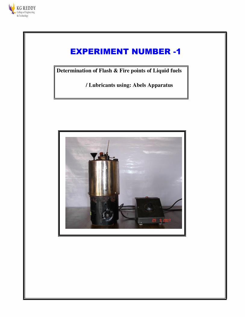
EXPERIMENT NUMBER -1
Determination of Flash & Fire points of Liquid fuels
/ Lubricants using: Abels Apparatus

ABEL’S FLASH AND FIRE POINT TEST
AIM
To determine the flash and fire point of the given sample of oil using Abel’s
apparatus closed cup methods.
APPARATUS
Abel’s apparatus, Thermo meter (0-110oC).
THEORY
This method determines the closed cup flash and fire points of petroleum products
and mixtures to ascertain whether they give off inflammable vapours below a certain
temperature.
FLASH POINT:
It is the lowest temperatures of the oil, at which, application of test flame causes the vapour
above the sample to ignite with a distinct flash inside the cup.
FIRE POINT:
It is the lowest temperature of the oil, at which, application of test flame causes burning for a
period of about five seconds.
DESCRIPTION
The apparatus consists of a brass cup and cover fitted with shutter mechanism, test
flame arrangement, hand stirrer, thermometer socket. The brass cup is heated by water bath
(with energy regulator), fitted with a funnel and overflow pipe.
PROCEDURE
1. Clean the oil cup and fill the up to the mark with the sample oil.
2. Insert the thermometer into the oil cup through the provision to note down the oil
temperature.
3. Using the Energy regulator, control the power supply given to the heater and rate of
heating
4. The oil is heated slowly when temperature of oil rises; it is checked for the flash point
for every one-degree rise in temperature.

5. After determining the flash point, the heating shall be further continued. The
temperature at which time of flame application that causes burning for a period at
least 5 seconds shall be recorded as the fire point.
6. Repeat the experiment 2 or 3 times with fresh sample of the same oil
7. Take the average value of flash and fire points.
PRECAUTIONS:
1. Stir the oil bath continuously to maintain the uniform temperature of sample oil.
2. The bluish halo that some time surrounds the test flame should not be confused with
true flash.
OBSERVATIONS:
Sample oil
Flash Point, 0
C
Fire Point, 0
C
RESULT
The flash point is observed at 0
C
The fire point is observed at 0
C

25

26
EXPERIMENT NUMBER -2
Determination of Flash & Fire points of
Liquid fuels/ Lubricants using: Pensky
Martens Apparatus

27
PENSKY MARTEN’S FLASH AND FIRE POINT TEST
AIM
To determine the flash and fire point of the given sample of oil using Pensky
Marten’s apparatus by both open and closed cup methods.
APPARATUS
o Pensky Marten’s apparatus,
o Thermometer (0-110oC).
THEORY
This method determines the closed cup and open cup flash and fire points of petroleum
products and mixtures to ascertain whether they give off inflammable vapours below a certain
temperature.
Flash Point: It is the lowest temperatures of the oil at which application of test flame causes the
vapour above the sample to ignite with a distinct flash inside the cup.
Fire point It is the lowest temperature of the oil, at which, application of test flame causes burning for
a period of about five seconds.
DESCRIPTION
The apparatus consists of a brass cup and cover fitted with shutter mechanism without shutter
mechanism (open cup), test flame arrangement, hand stirrer (closed cup), thermometer socket, etc.,
heated with energy regulator, a thermometer socket made of copper.
PROCEDURE
1. Clean the oil cup thoroughly and fill the oil cup with the sample oil to be tested up to the
mark.
2. Insert the thermometer into the oil cup through a provision, which measures the rise of oil
temperature.
3. Using the Energy regulator, control the power supply given to the heater and rate of heating
4. The oil is heated slowly when temperature of oil rises, it is checked for the flash point for
every one degree rise in temperature.
5. After determining the flash point, the heating shall be further continued. The temperature at
which time of flame application which causes burning for a period at least 5 seconds shall be
recorded as the fire point.

28
6. Repeat the experiment 2 or 3 times with fresh sample of the same oil
7. Take the average value of flash and fire points.
PRECAUTIONS
1 Stir the oil bath continuously to maintain the uniform temperature of sample oil.
2. The bluish halo that some time surrounds the test flame should not be confused with true
flash.
OBSERVATIONS
Sample oil
Flash Point, 0
C
Fire Point, 0
C
RESULT
The flash point is observed at 0
C
The fire point is observed at 0
C

PENSKY MARTEN’S FLASH AND FIRE POINT TEST

EXPERIMENT NUMBER -3
Carbon residue test: Liquid fuels

CONRADSON CARBON RESIDUE TEST
AIM: To determine the percentage of carbon residue of the given oil using Carbon Residue test
apparatus.
APPARATUS: a) Porcelain crucible, b) Iron Crucible, Skidmose c) spun sheet iron crucible d)
wire support e) Hood f) insulator and g) burner.
THEORY:
Oils contain mainly chemical compounds of carban and Hydrogen. If heated in a closed
vessel in the absence of sufficient air, the oil will vapourise and a thin deposit of carban residue
will be left behind. This test serves as index and gives some relative measure of the amount of
residue to be formed by lubricating oils, especially in IC Engines.
DESCRIPITION:
Conradson Carbon residue tester consists of a glazed porcelain crucible (5) of about 25 to
26 ml. capacity, placed in iron crucible (4) of 60 to 88 ml, approximate capacity and having a
cover with an opening of 5 to 6 mm dia. The two together are placed in a spun sheet iron crucible
(3) with cover, about 200 ml. capacity at the bottom of which is placed a level layer of about 25
ml. clean dry sand such that the iron crucible containing the glazed porcelain crucible with its
cover on it is brought to the top of the sheet iron crucible. The bottom of the sheet iron crucible
is supported by a triangular base, Nichrome wire, circular sheet iron hood (1) with a sloping top
and provided with central chimney, encloses the crucible. A hollow sheet iron block provided
with an opening in the centre, for the spun sheet iron crucible to kept rests on iron stand.

PROCEDURE:
1. The crucible is weighed accurately.
2. About 10 gms of oil to be tested for carbon residue is taken in the crucible and weighed.
3. This crucible is placed in the centre of the iron crucible.
4. Now sand is taken in the spun sheet iron crucible and is evenly spread and on the sand bed the iron
crucible with the glazed porcelain crucible containing the oil sample is placed.
5. The whole assembly is placed in the sheet iron block and the cover is put in position.
6. The hood is placed on the block and heat is applied with the burner at the bottom of the spun iron
crucible.
7. After about 20 to 25 minutes of heating, the cover is slightly displaced to make the vapour escape,
simultaneously introducing a lighted splinter in the hood.
8. If sufficient vapours have formed, they will catch fire and continue to burn.
9. When the flame dies down, it means all the oil taken has been vaporized.
10. The hood is removed first, then, the cover is lifted, the crucible is taken out and placed in a
designator for getting cooled.
11. After the crucible is cooled down to ambient temperature, it is weighed again.
12. The difference between the initial and final weights of the crucible give the amount of carbon
residue and is expressed as a percentage of carbon residue as shown in the calculation
NOTE: For sample having carbon residue from 5 to 10% sample of 5+0.5 gm is to be taken. If
the carbon residue exceeds 15% a sample of 3 + 0.1 gm should be taken.
CALCULATIONS:
Weight of crucible with glass beads =W1
Weight of crucible with oil =W2
Weight of oil taken =W0=W2-W1
Weight of the crucible and residue = W3
Weight of the carbon residue = Wc = W3- W1
Percentage of carbon residue = (p.c) = Wc/Wo x 100
RESULT:
The percentage of carbon present in given sample of lubricating oil is %

16 SAYBOLT VISCOMETER
CARBON RESIDUE (CONRADSON) APPARATUS

17 SAYBOLT VISCOMETER
EXPERIMENT NUMBER -3
SAYBOLT VISCOMETER

`
SAYBOLT VISCOMETER
AIM: To determine the viscosity of lubricating oil by using a saybolt viscometer.
APPARATUS: Saybolt viscometer, stop watch and water bath thermometers.
THEORY:
Viscosity of lubricating oil is measured by an instrument known as viscometer. Most of
the viscometers are of efflux type. In these, a measured volume of oil at a particular
temperature is allowed to efflux through a capillary tube and the time of flow is noted in
seconds. Saybolt viscometer is employed by the oil industry in U.S.A. The units of dynamic
viscosity in M.K.S and S.I systems are centipoise and MPa-s respectively. Similarly the units of
kinematic viscosity ‘ν’ in M.K.S and S.I systems are centistokes and m2/s respectively.
(i) Viscosity (µ): Viscosity is a measure of resistance to relative translational motion of
adjacent layers of a fluid. It is the property of a fluid. The unit of viscosity is poise or centipoise
(cp).
(ii) Specific viscosity: Specific viscosity is the ratio of the viscosity of fluid to the viscosity of
water at 200 C. Since the water has a viscosity of 1cp at 200 C.
(iii) Kinematic viscosity (ν): Kinematic viscosity is defined as the ratio of dynamic viscosity
(µ) to the density (ρ) of the fluid.
DESCRIPTION:
It consists of a universal container containing the liquid which is allowed to discharge
through a standard orifice in a tip fitted at the centre of the case container. There are two tips,
(i) Universal tip and (ii) Furol tip. Furol tip is for less viscous and universal tip for all liquids
usually for highly viscous liquids. The bath stirring is fitted with a thermometer collar, knobs
for holding and stirring and also provisions for electric heating by means of an electric heating
coil and a ‘U’ tube to heat the bath by steam or to cool the bath if need be by water circulation
and these are fitted in the bath stirred cover. Bath and stirrer are finished in highly polished
chromium plating to facilitate cleaning and are mounted on a stand with leveling feet. A cork is
provided at the bottom of the oil cup to cause or prevent flow of oil when it is not in position or
when it is in position.
PROCEDURE:
1. Fill the required quantity of water in the water container.
2. Plug the bottom of the orifice by rubber cork and fill the tube with the oil sample.
3. Switch on the supply of the bath heater. As the oil temperature reaches 400 C and becomes
steady, place the measuring flask and funnel in position to collect the oil.
4. Remove the rubber cork out and start noting the time till the oil level reaches 50 cc mark in the
measuring flask.
5. Record the time in second.
6. Repeat the experiment at different temperatures of the oil and record the corresponding timings.

`
7. Calculate the viscosity of oil for each temperature setting.
OBSERVATIONS:
Sl
no.
Temperature of oil
(0C)
Time of
collection for
50cc, ‘t’ (s)
ν
(centistokes)
CALCULATIONS:
ν = At – B/t centistokes
Dynamic viscosity, µ = ν x ρ
where, ρ = density of oil in kg/m3
t = time in second
A and B are the constants of viscometer
For 34 < t < 115, A = 0.224 & B = 185
For 115 < t < 215, A = 0.223 & B = 115
PRECAUTIONS:
1. The position of the measuring flask should be such that the oil strike the flared mouth of the
funnel and does not drop directly into the flask since this may trap air and cause foaming.
2. The temperature of the oil in the oil – tube should be maintained constant to avoid errors as the
viscosity is the function of temperature.
LIMITATION OF SAYBOLT VISCOMETER:
The instrument should be used only where laminar flow exists in the tube, and the time
is above 40 seconds for flow of 60cc of oil.

`
CONCLUSION:
Viscometers are helpful in determining and establishing the degree of viscosity of a
particular fluid at particular time and temperature.
GRAPHS:
1. Absolute viscosity V/s Temperature
2. Kinematic viscosity V/s Temperature
Temp Temp

`

`
REDWOOD VISCOMETER

`
REDWOOD VISCOMETER – I
AIM: To determine the absolute and kinematic viscosities of given lubricating oil at various
temperatures starting from room temperature.
APPARATUS: Redwood viscometer – I, thermometers, stop-watch, measuring flask (50 cc), spirit level,
glass jar and oil (SAE 20 / SAE 40).
THEORY:
(i) Viscosity (µ): Viscosity is a measure of resistance to relative translational motion of adjacent layers
of a fluid. It is the property of a fluid. The unit of viscosity is poise or centipoise (cp).
(ii) Specific viscosity: Specific viscosity is the ratio of the viscosity of fluid to the viscosity of water at
200 C. Since the water has a viscosity of 1cp at 200 C.
(iii) Kinematic viscosity (ν): Kinematic viscosity is defined as the ratio of dynamic viscosity (µ) to the
density (ρ) of the fluid.
EFFECT OF TEMPERATURE ON VISCOSITY:
Increase in temperature causes a decrease in the viscosity of a liquid, where as viscosity of gases
increases with temperature growth. The viscous forces in a fluid are the outcome of intermolecular
cohesion and molecular momentum transfer. In liquids the molecules are comparatively more closely
packed, molecular activity is rather small and so the viscosity is primarily due to molecular cohesion.
DESCRIPTION:

`
The redwood viscometer consists of a heavily silver plated oil cup with a dished bottom placed in a
bright chrome plated water bath. The water bath is mounted on a stand with leveling screws. The level
to which the oil is to be filled into cup is given by and index fixed to the inside wall of the oil cup. A
standard size jet of stainless steel is fitted at the centre of the bottom of the cup for the flow out of oil
of liquid to be measured. The cylindrical water bath is provided with a tap for emptying.
The bath of liquid is stirred manually by means of a cylinder surrounding the oil cup provided with
three vanes, having their upper and lower portions turned in opposite directions.
The valve for starting and stopping the flow of the liquid from the oil cup consists of a ball carried
on a stiff wire, both heavily silver plated.
The oil cup cover is fitted with an insulated handle and has suitable slots for the slots for the oil-cup
thermometer and valve rod. The circular spirit level is mounted on a plate to fit on the upper end of
the oil cup.
POCEDURE:
1. The oil cup is cleaned with a suitable solvent, for example, Carbon tetrachloride and then dry it
thoroughly using tissue paper or some similar material which will not leave any fluff. Examine the jet and
ensure that it is clean and not obstructed.
2. The viscometer is leveled by using the level feet. The viscometer bath is heated to a few degrees above
the desired test temperature.
3. The prepared sample of the oil is poured into the oil cup through filler of metal gauge not coarser than
BS 100 mesh. Mesh size indicates the number of holes divided in one square inch area.
4. The temperature of bath is adjusted until the sample in the cup is maintained at the test temperature.
Stirring the contents of the bath and cup during the process be assured, preferably using continuous
stirring for both.
5. The sample is stirred during the preliminary period, for example, by means of ball valve, closing the
bottom of the jet by suitable means, but not during the actual determination.
6. When the temperature of the sample has become quite steady at the desired value, the liquid level is
adjusted by allowing the sample to flow out until the surface of the sample touches the filling point.
7. The oil cup cover is placed and the oil cup thermometer id swung towards the closed end of the curved
slot in the cover.

`
8. The clear, dry, standard 50 cc flask is placed centrally below the jet with the top of the neck a few mm
from the bottom of the jet. Redwood viscometer – I is suitable for measurement of viscosity less than
2000 seconds.
9. The flask is not insulated in any way. The ball valve is lifted and simultaneously the time recorder is
started.
10. The time recorder is stopped at the instant the sample reaches the graduation mark of the flask and the
final reading of the oil cup thermometer is noted.
11. The procedure is repeated for various temperatures and the time in second is noted at each
temperature and the results are tabulated.
OBSERVATOIN:
Oil sample:
Mass of the collecting flask, m1 =
Sl.
No
.
Oil
temperature
, ‘t’ 0C
Time
taken
to
collect
50 ml
of oil,
‘R’
secon
d
Mass of
flask
with 50
ml
collectin
g oil, m2
Kg
Oil
density
, ‘ρ’
kg/m3
Kinemati
c
viscosity,
‘γ’
m2/s
CALCULATIONS:

`
Kinematic viscosity = AR – B/R in centistokes
where, A & B are viscometer constants
A = 0.26 B = 171.5
R = time in second for collection of 50 cc of oil in the flask.
Absolute viscosity = Kinematic viscosity x density = γρ in centipoise
CONCLUSION:
Viscometers are helpful in determining and establishing the degree of viscosity of a particular
fluid at particular time and temperature.
GRAPHS:
3. Absolute viscosity V/s Temperature
4. Kinematic viscosity V/s Temperature
Temp Temp

`
`
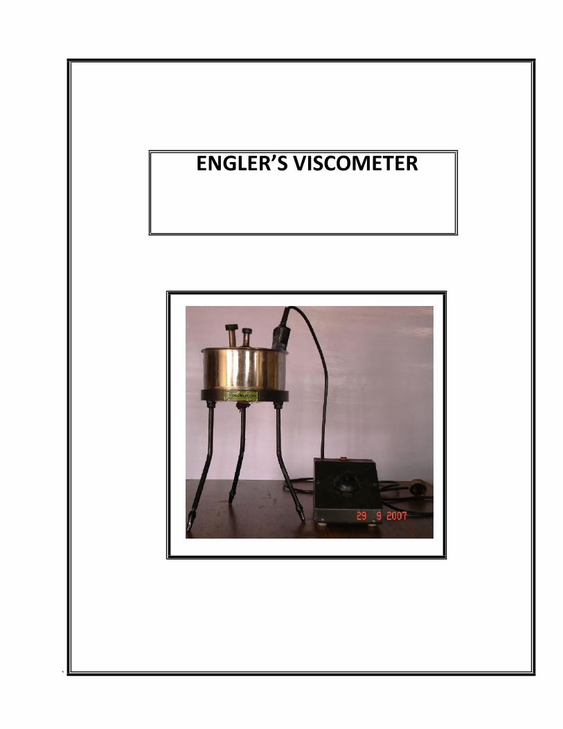
ENGLER’S VISCOMETER
`
ENGLER’S VISCOMETER
AIM
To determine the viscosity in Engler’s seconds of the given samples of oil and to
plot the variation of Engler’s seconds, kinematic and dynamic viscosity with
temperature.
APPARATUS
o Engler’s viscometer,
o Stopwatch,
o Thermometer (0-1000C)
o Measuring flask (200 c.c.).
THEORY
The viscosity of given oil is determined as the time of flow in Engler’s seconds.
The viscosity of a fluid indicates the resistance offered to shear under laminar condition.
Dynamic viscosity of a fluid is the tangential force on unit area of either of two parallel
planes at unit distance apart when the space between the plates is filled with the fluid
and one of the plate’s moves relative to the other with unit velocity in its own plane. The
unit of dynamic viscosity is dyne-sec/cm2. Kinematic viscosity of a fluid is equal to the
ratio of the dynamic viscosity and density of the fluid. The unit of kinematic viscosity is
cm2
sec
DESCRIPTION
Engler’s viscometer consists of a water bath and oil bath, both provided with two
thermometers inside them. There is an ebonite valve stick, which is located at center of
oil bath to flow of oil through the orifice. A heater with regulator is fixed for heating
purpose.
PROCEDURE
1. Clean the oil cup with a suitable solvent thoroughly and dry it using soft tissue paper.
.

`
2. Keep the ebonite valve stick in its position so as to keep the orifice closed.

`
3. The water is taken into the water bath and the oil whose viscosity is to be determined
is taken into the oil cup up to the mark.
4. Before switch on the electric supply, at room temperature note down the time taken in
Engler’s seconds for a collection of 200cc. of oil with a stopwatch.
5. Heat the bath and continuously stir it taking care to see that heating of the bath is done
in a careful and controlled manner.
6. When the desired temperature is reached, place the cleaned 200 c.c. Flask below the
orifice in position.
7. Remove the ebonite valve stick and simultaneously start a stopwatch. Note the time of
collection of oil up to the 200 c.c. Mark. During the collection of oil don’t stir the bath.
8. Repeat the process at various temperatures.
OBSERVATIONS
S. No.
Oil
Temperature
0C
Time for
collecting
50 c.c. of
oil
sec
Kinematic
viscosity
ν = (A × t )− B
t
cm
2
sec
Density
(ρ)
gm sec
Absolute
Viscosity
µ = ν × ρ
dyne − sec
cm2

`
Where
A = 0.0026 cm2
B = 1.8 cm2/sec2
GRAPHS TO BE DRAWN
1. Engler’s seconds vs. temperature
2. Kinematic Viscosity vs. temperature
3. Absolute Viscosity vs. temperature
MODEL GRAPHS
Engler’s seconds Kinematic Viscosity Absolute Viscosity
PRECAUTIONS
1. Stir the water continuously so that the temperature of the oil and water are equal.
2. Before collecting the oil at a temperature, check whether the oil is up to the Indicator in
the oil cup.
3. Always take the readings at a stable temperature
4. Ensure proper setting of the Ebonite stick to avoid leakage
RESULTS
Variation of Engler’s seconds, Absolute viscosity and Kinematic viscosity with
temperature, were observed and found to be decreasing with temperature.
Te
mp
Te
mp
Te
mp

55
ENGLER’S VISCOMETER

56
JUNKER’S GAS CALORIMETER

57
JUNKER’S GAS CALORIMETER
AIM: To determine the calorific value of the given gaseous fuel (LPG).
APPARATUS: Junker’s gas calorimeter, measuring jar, rubber tubing and corks,
thermometers gas flow meter.
PROCEDURE:
1. Place the apparatus preferably at the end of the test bench and nearer to sink
as shown in the sketch so that there will be space to keep the measuring jar
beneath the swinging outlet arm and the sink can be used to drain the
overflowing water.
2. Adjust the leveling screws of the calorimeter so that the entire apparatus is in
vertical position. Insert the thermometers into their respective positions as
shown in figure, keeping the scales visible and conveniently to the observer.
3. Connect the outlet end of the gas flowmeter to the burner by means of the
rubber tube supplied. Level the gas flowmeter using the spirit level and
adjusting the leveling screws.
4. Pour in the water through the hole provided for inserting the thermometer till it
reaches the mark on the glass window. Now fix the thermometer in flowmeter.
5. Connect the outlet of the pressure governor to the inlet of flowmeter by rubber
tubing. Remove the knurled head screw from the overflow tube of the

58
governor. Lift the float lightly by holding the thread and pour water till water
overflows through the side wall tube. Replace back the
6. knurled head screw tightly. Connect the inlets of the governor to the gas supply.
7. Connect the water supply from over head cistern or water tap to water inlet.
Connect the rubber tube to the water flow tube, the outlet end of which is
placed in a sink.
MAKING A TEST:
1. Turn on the water mains by opening the control knob of the gas calorimeter to
setting ‘ON’. Adjust the water supply in such a way that there will be only a
small amount of overflow of excess water to sink. By this the air bubbles inside
the water circulation will be out
2. Remove the burner from the calorimeter. Open the tap of the governor. Allow
the gas to pass for three of four revolutions as indicated by the flowmeter. Then
light the burner and adjust the air regulator sleeve and the gas tap to get a non-
luminous flame.
3. Clamp the burner keeping it to the top most position. Then adjust the flow of
water to get a temperature difference of 120 C to 150 C between the water inlet
and outlet temperature. This is important if the flow of water is less than

59
required; there will be a high temperature difference and the water may escape
as steam.
4. Keep the measuring jar beneath the swinging water outlet tube and
simultaneously count the number of revolutions made by the gas flowmeter
pointer, i.e., to find volume of gas consumed during the test period. When the
pointer has made 2 to 3 revolutions, swing the water outlet back to drain.
5. Also, immediately note the temperatures of water inlet and outlet as well as gas
flowmeter and amount of water collected in the measuring jar.
OBSERVATION AND CALCULATION:
Vw = Volume of water collected in the measuring jar =
Vg = Volume of gas from the gas flowmeter =
T1 = Water inlet temperature =
T2 = Water outlet temperature =
Therefore, calorific value of the gas is given by
Cv = (Vw / Vg) x (T2 – T1) x 1000 kcal/m3
= (Vw / Vg) x (T2 – T1) x 1000 x 4.2 kJ/m3

60

61
BOMB CALORIMETER
62
BOMB CALORIMETER
AIM:
To determine the calorific value of the given solid fuel by bomb
calorimeter.
APPARATUS:
Bomb calorimeter, water jacket, stirrer, pressure gauge with stand, pellet
press, crucible, ignition wire and given fuel.
THEORY:
Bomb calorimeter is normally used for determining the higher calorific value
of solid fuels. However, it is also used for liquid fuels. The combustion of the
fuel takes place at constant volume in a totally enclosed vessel. Thus higher
calorific value at constant volume is determined. If the combustion leads to
reduction in volume of the products when reduced to initial temperature, the
values obtained are different from actual heat liberated.
(i) Calorific value of fuel (Cv): The calorific value of fuel is defined as the amount of
heat liberated by the complete combustion of a unit quantity of fuel. In SI units,
for solid and liquid fuels, it is expressed in terms of kJ/kg of fuel and for gaseous
fuels in kJ/m3 at STP (Standard temperature and pressure). The two types of
calorific values are higher calorific value and lower calorific value.
(ii) Higher calorific value (HCv): The higher calorific value of fuel is defined as the
amount of total heat obtained by the complete combustion of a unit quantity of

63
fuel when the products of its combustion have been cooled down to the
temperature of air supplied.
(iii) Lower calorific value (LCv): The lower calorific value fuel is defined as the net
heat obtained when the heat absorbed by water vapour formed during the
combustion is not recovered.
DESCRIPTION:
The bomb calorimeter consists of a strong stainless steel shell which is
known as the bomb. Inner surface of the bomb is coated with special enamel
to prevent corrosion of acids formed as a result of combustion of fuel
containing sulphur or nitrogen. The capacity of the bomb is 303 cc and it can
withstand a pressure up to 300 atm. Bottom of the shell is screwed in a cover
which forms the base of the shell. Though the threads are gas tight, water is
filled in the bomb to a specified level to act as water seal; also a rubber ‘O’
ring is used. The oxygen connection and the pressure release valve are placed
in the top cover . Bottom cover of the bomb supports two uprights, one of
them carrying a ring to support crucible made of stainless steel . The lid is
provided with two insulated firing plugs through which the leads from the
main supply are taken via a rheostat . During a test, the bomb is placed in a
copper vessel known as calorimeter which contains 2000 cc of water that is
agitated by stirrer run by a motor at a constant speed . The calorimeter is
surrounded by an outer double walled vessel with water jacket and air space
between these two containers to reduce radiation loss. A fitting for the
thermometer is provided in the calorimeter.
64
PRINCIPLE OF OPERATION:
A known amount of the sample is burnt in a sealed chamber (hereafter we
shall refer to the chamber as bomb). The air is replaced by pure oxygen. The
sample is ignited electrically. As the sample burns, heat is produced . The rise
in temperature is determined . Since, barring loss of heat, the amount of heat
produced by burning the sample must be equal to the amount of heat
absorbed by the calorimeter assembly, a knowledge of the water equivalent of
the calorimeter assembly and of the rise in temperature enables one to
calculate heat of combustion of the sample.
PROCEDURE:
1. About one gram of the fuel is weighed in the crucible; a piece of firing wire is
stretched between the electrodes in such a manner that it is in close contact
with the fuel so that it can be ignited.
2. Often the powdered coal is made into a small pellet with the fuse wire inserted
in it, weighed and placed in the crucible.
3. The cap is screwed down on the bomb and oxygen is filled in the cup to a
pressure of about 200 atm. The bomb is then placed in a weighed amount of
water, taken in the calorimeter.
4. Electrical connections are made, stirring is started and temperature reading is
taken with a thermometer reading to .010 C.
5. When the thermometer shows a steady temperature the fuel is made to fire
and temperature readings are continued for few minutes after the maximum
temperature is attained.
6. The water is stirred during the experiment.

65
7. The bomb is then removed and allowed to stand so that the acid mist may settle
down. The pressure is slowly released and the contents of the bomb are
carefully washed.
8. In actual practice correction needs to be made for the heat of fuse wire.
PRECAUTIONS:
1. Do not use too much sample. The bomb cannot be expected to stand with the
effects of combustible charges which liberate more than 10,000 calories. This
generally limits the total weight of combustible material (sample plus gelatin,
firing oil or any combustible aid) to not more than 1.1 gram. Do not charge with
more oxygen than is necessary and do not fire the bomb if an overcharge of
oxygen should accidentally be admitted.
2. Keep all parts of the bomb especially the insulated electrode assembly in good
repair at all times. Do not fire the bomb if gas bubbles are leaking from the
bomb when it is submerged in water.
3. Stand back from the calorimeter for at least 15 seconds after firing the above
all, keep clear of the top of the calorimeter. If the bomb should explode, it is
most likely that the force of explosion will be directed upwards.

66
CALCULATION:
Water equivalent of calorimeter
W = HM + (CVt + CVw) T
where, H = Heat of combustion of given fuel in calories per gram =
6319cal/gram
W = Water equivalent of calorimeter
M = Mass of given fuel sample in grams = .95 gm( 1gm aprox)
CVt=considered calories of cotton thread (10cm) x (2.1) = 21cal
CVw=considered calories of nicrome wire (4cm) x (2.33) = 9.32cal
T = Temperature rise in 0C = T2 – T1 = 2.60 C
T1 = Initial temperature in 0C
T2 = Final temperature in 0C
WT = HM
where, W = water equivalent of calorimeter = J/ 0C
= 6319x0.955+( 21+9.32)/2.609
= 2325 cal/oc
Formula for calorific value of sample
CVs= TxW- (CVt + CVw) / M

67
OBSERVATION:
Mass of the sample =
Initial temperature =
Final temperature =
Water equivalent =
Sl.
No.
Time (s) Temperature (0
C)

68
Time

69

70
PENETRATION TEST
71
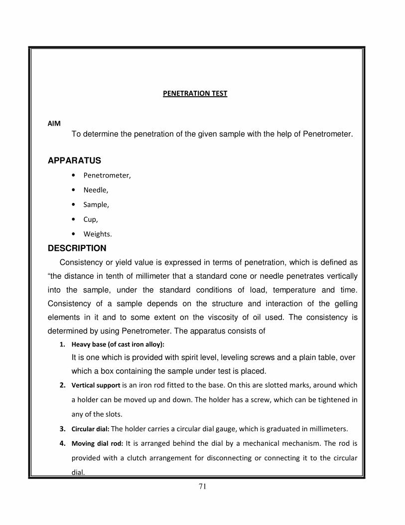
AIM
PENETRATION TEST
To determine the penetration of the given sample with the help of Penetrometer.
APPARATUS
• Penetrometer,
• Needle,
• Sample,
• Cup,
• Weights.
DESCRIPTION
Consistency or yield value is expressed in terms of penetration, which is defined as
“the distance in tenth of millimeter that a standard cone or needle penetrates vertically
into the sample, under the standard conditions of load, temperature and time.
Consistency of a sample depends on the structure and interaction of the gelling
elements in it and to some extent on the viscosity of oil used. The consistency is
determined by using Penetrometer. The apparatus consists of
1. Heavy base (of cast iron alloy):
It is one which is provided with spirit level, leveling screws and a plain table, over
which a box containing the sample under test is placed.
2. Vertical support is an iron rod fitted to the base. On this are slotted marks, around which
a holder can be moved up and down. The holder has a screw, which can be tightened in
any of the slots.
3. Circular dial: The holder carries a circular dial gauge, which is graduated in millimeters.
4. Moving dial rod: It is arranged behind the dial by a mechanical mechanism. The rod is
provided with a clutch arrangement for disconnecting or connecting it to the circular
dial.

72
5. Mirror: Vertical rod is provided with an adjustable mirror for removing parallax error
while positioning the cone or needle in contact with sample surface.
73
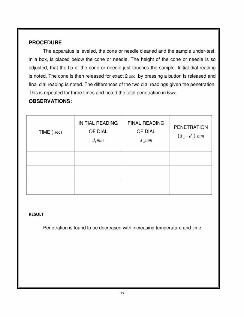
PROCEDURE
The apparatus is leveled, the cone or needle cleaned and the sample under-test,
in a box, is placed below the cone or needle. The height of the cone or needle is so
adjusted, that the tip of the cone or needle just touches the sample. Initial dial reading
is noted. The cone is then released for exact 2 sec, by pressing a button is released and
final dial reading is noted. The differences of the two dial readings given the penetration.
This is repeated for three times and noted the total penetration in 6 sec.
OBSERVATIONS:
TIME ( sec)
INITIAL READING
OF DIAL
d1 mm
FINAL READING
OF DIAL
d 2 mm
PENETRATION
(d 2 − d1 ) mm
RESULT
Penetration is found to be decreased with increasing temperature and time.

50
GREASE PENETROMETER

51
ASTM DISTILLATION TEST APPARATUS

52
ASTM METHOD FOR DISTILLATION OF PETROLEUM
PRODUCTS AT ATMOSPHERIC PRESSURE
1. ASTM method for Distillation of Petroleum Products at atmospheric pressure
Objectives Determining the boiling range of Kerosene and the curve by using ASTM distillation. Introduction: This test method covers the atmospheric distillation of
petroleum products using a laboratory batch distillation unit to determine quantitatively the boiling range characteristics of such products as light and middle distillates,
automotive spark-ignition engine fuels with or without oxygenates ,aviation gasolines, aviation turbine fuels, diesel fuels, biodiesel blends up to 20 %, marine fuels, special
petroleum spirits, naphthas, white spirits, kerosines, and Grades 1 and 2 burner fuels. • The test method is designed for the analysis of distillate fuels; it is not applicable to
products containing appreciable quantities of residual material. • This test method covers
both manual and automated instruments. • This test method provides an estimate of the
yields of fractions of various boiling ranges, and is therefore valuable in technical
discussion of a commercial natural. This test method corresponds to the standard
laboratory distillation efficiency referred to as 15/5 This test method can be used for any
petroleum product expect LPG , very light Napthas and fractions having initial boiling
point above 400 o C.this test method employs a fractionating column having an
efficiency of 14 to 18 theoretical plates operated at a reflux ratio of 5:1 .
2. Materials and Instruments: 1. Distillation Flasks. 2. Condenser and Condenser Bath. 3.
Heater. 4. Thermometer. 5. Graduated cylinder. 6. Gasoline 100 mL 7. Themormeter
Distillation Flask Burner or Heater Stand Condense Graduated Cylinder
3. Procedure: 1. A 100 mL of the Sample in our experiment is (Gasoline) add to the
distillation flask .
2. We heat this flask in a regulated rate , so that a uniform average rate of
condensation in mL/min is maintained. 3. When the first drop appears at the lower end of the condenser tube, the thermometer reading (vapor temperature) is recorded ,
this temperature is the initial boiling point (IBP). 4. We record the temperature at several Volume% distilled up to the final boiling point (FBP) and heating
discontinued. 5. After flask cooled the volume of remaining liquids is measured and
recorded as the recovery. Calculation Volume Percent distilled Temperature o C 0 54 5 59 10 65 20 74 30 83.5 40 94.5 50 104.5 60 114 70 125.5 80 141.5 90 173 95
178 FBP 180 The Final Boiling point of the product = 180 o C Volume Distilled = 96 mL Residue left = 2 mL Evaporated = 2 mL
4. A plot of volume percent distilled and temperature can be plotted as shown below:
Discussion • What information does the boiling range give on the composition, the properties and behavior of the fuel during storage and use ? Degree API gravity
decrease, with the increase of mid percent boiling point temperature of the narrow
fractions, because the value of API is inversely related to specific gravity. 0 20 40 60 80
100 120 140 160 180 200 0 10 20 30 40 50 60 70 80 90 100 Y-Values

53
5. As shown at the figure above , the API gravity decrease with the increase the
temperature, this relation can explain all the change in petroleum products composition
with the change of boiling point, if the boiling point increase the API gravity decrease
resulting in heavy crude oil contain much hydrocarbons with aromatic hydrocarbons ,
this crude oil will contain less gasoline and will not be commercial , and if the boiling
point decrease it will make the inverse. If the boiling range of petroleum products were
low , the petroleum products will be Volatile and easy to evaporate that’s make the
storage and transferring of such products is dangerous , also in our life if boiling range
of some petroleum products were low it will evaporate quickly make a toxic gases that
we can breathing them causing problems. Also when the boiling ranges are high it will
effect at the Efficiency of them and the ability to burn inside the engines. • how can
distillation characteristics of hydrocarbon affect their safety and performance ? when the petroleum products are distillated , the different hydrocarbons compounds inside the
petroleum products will separate that cause decreasing in boiling point of the distillated fraction making it easy to evaporate and explosive . • what is the major determinant of
the tendency of a hydrocarbon mixture to produce potentially explosive ? the major determinant of the tendency of a hydrocarbon mixture to produce potentially explosive
is the boiling range of the hydrocarbons inside the mixture, if the boiling range is low the mixture is more able to explosive . • what are factors affecting on the accuracy of the
results ? There many factors affecting on the accuracy of this experiment , first the loses
of vapor from the flask when it evaporate , if the flask hole around the thermometer was
not closed completely , some of the vapor will run out from the flask without going
through the condenser , to solve this problem we should close the hole around the
thermometer with piece of rubber. Another problem that affect the results is if the
cylinder that we calculate the distillated vapor in it was open from the top without any
filter paper on it , some of the vapor that have not distillated will go out
6. from the cylinder by the opened top , to solve this problem we should put a filter paper
at the top of cylinder . Also if the condenser was not efficiency the vapor will not
distillated into liquid this is also effect on the results. Conclusion Boiling range points is
important property of petroleum products , when we send the products to the industries ,
they should have information about the properties of the petroleum products and one of them is the boiling range , and also its important to take careful from the volatile liquid
that are dangerous and toxic.

54

55
CLOUD & POUR POINT TEST

56
CLOUD & POUR POINT TEST
AIM: To determine the cloud & pour point of a given fuel / lubricant / oil, using
cloud &pour point apparatus.
APPARATUS:
Cloud & pour point apparatus,
Digital stem thermometer
THEORY:
CLOUD POINT: The temperature, expressed to the nearest degree
centigrade, at which a cloud or haze appear when the oil is cooled under
prescribed conditions.
POUR POINT: The lowest temperature, expressed as a multiple of 30 c, at
which the oil is observed to flow when cooled & examined under prescribed
conditions.
PROCEDURE:
CLOUD POINT:
1. Bring the sample to a temperature of at least 15 0
Cabove the approximate cloud
point and pour it into the jar to a height of 51 to 57 mm.
2. Close the jar with the cork so that the thermometer bulb rests on the centre of the
bottom of the jar.
3. Fit the gasket on to the jar 25 mm from the bottom and insert the jar into gasket.
4. Support the jacket and jar in a vertical position in the bath so that not more than
25 mm projects from the cooling medium.
5. At each thermometer reading of one degree centigrade, remove the jar from the
jacket quickly but without disturbing the oil, inspect the material for cloud, and
replace the jar, this complete operation shall not take more than 3 sec.
6. If the sample does not show a cloud when it has been cooled 10 0 C. Place
the jar and jacket in another bath maintained at a temperature of -15 0 C to
-18 0 C.

57
7. If the sample does not show a cloud when it has been cooled to -7 0 C. Place the
jar and jacket in another bath maintained at a temperature of
-32 0 C to -35
0 C.
8. When an inspection of the sample first reveals a distinct cloudiness or haze at the
bottom of the jar, record the reading of the thermometer as the cloud point after
correcting the thermometer errors if necessary.
POUR POINT:
1. The sample has cooled enough to allow the formation of the crystals.
2. Maintain the bath temperature at -1 0 C to 2
0 C
3. Support the jacket and jar in a vertical position in the bath so that not more than
25 mm projects from the cooling medium.
4. Beginning at a temperature 12 0 C above the expected pour point, at each
thermometer reading which is a multiple of 3 0 C, remove the jar from the
jacket carefully, and tilt it just enough to see whether the oil will move and
the replace it, this complete operation shall not take more than 3 sec.
5. As soon as the sample ceases to flow when the jar is tilted, hold the jar in
horizontal position for exactly 5 sec.
6. If the sample shows any movement replace the jar in the jacket and cool down the
sample for another 3 0
C. If the oil shows no movement during the 5 sec, record
the reading of the thermometer.
7. Add 3 0 C to the temperature recorded above and corrected for thermometer
errors if necessary, and note down the result as the pour point.
OBSERVATIONS:
OIL CLOUD POINT ( 0 C) POUR POINT ( 0
C)

58
PRECAUTIONS:
2. The disc, the gasket, and jacket shall be kept clean and dry.
3. Don’t disturb the mass of sample nor don’t permit the thermometer to shift in the
sample. Any disturbance of the spongy network of crystals will lead to false results.
RESULT:
For a given sample of oil the Cloud & Pour point s are and
respectively.

59
CLOUD & POUR` POINT APPARATUS