fuel injection pump gear - remove removal procedure · 2015-05-19 · fuel injection pump gear -...
TRANSCRIPT

Fuel Injection Pump Gear - Remove
Removal Procedure
Table 1
Required Tools
Tool Part Number Part Descriptions Qty
A (1) 9U-6198 Crankshaft Turning Tool 1
A (2)9U-7336 Housing 1
5P-7305 Engine Turning Tool 1
B 230-6284 Timing Pin (Camshaft) 1
C 230-6283 Timing Pin (Crankshaft) 1
D 1P-2320 Combination Puller 1
( 1 ) The Crankshaft Turning Tool is used on the front pulley.( 2 ) This Tool is used in the aperture for the electric starting motor.
Start By:
A. Remove the front cover. Refer to Disassembly and Assembly, "Front Cover - Remove and Install".
Note: Either Tooling (A) can be used. Use the Tooling that is most suitable.
NOTICE
Keep all parts clean from contaminants.
Contaminants may cause rapid wear and shortened component life.

NOTICE
Care must be taken to ensure that fluids are contained duringperformance of inspection, maintenance, testing, adjusting and repairof the product. Be prepared to collect the fluid with suitable containersbefore opening any compartment or disassembling any componentcontaining fluids.
Dispose of all fluids according to local regulations and mandates.
Note: Care must be taken in order to ensure that the fuel injection pump timing is not lost during the removal ofthe fuel pump gear. Carefully follow the procedure in order to remove the fuel pump gear.
1. Use Tooling (A) in order to rotate the crankshaft so that number one piston is at the top center position onthe compression stroke. Refer to Systems Operation, Testing and Adjusting, "Finding Top Centre Positionfor No.1 Piston".
Typical example
2. Install Tooling (B) through Hole (X) in camshaft gear (1) into the front housing. Use Tooling (B) in order tolock the camshaft in the correct position.

3. Install Tooling (C) into Hole (Y) in the front housing. Use Tooling (C) in order to lock the crankshaft in thecorrect position.
Note: Do not use excessive force to install Tooling (C). Do not use Tooling (C) to hold the crankshaft duringrepairs.
Typical example
4. Apply sufficient pressure to fuel injection pump gear (2) in a counterclockwise direction in order to removethe backlash. Lock fuel injection pump (3) in this position.
In order to lock fuel injection pump (3), loosen locking screw (4) in the fuel injection pump. Slide spacer (5)into Position (YY). Tighten locking screw (4) against the shaft of the fuel injection pump to a torque of 9N·m (80 lb in).

Alignment of timing marks
5. Mark gear (1), gear (2) and gear (7) in order to show alignment. Refer to Illustration 3.
Note: Identification will ensure that the gears can be installed in the original alignment.
6. Loosen nut (6) on fuel pump gear (2) .
7. Install Tooling (D) through three holes in fuel pump gear (2). Tighten Tooling (D) until the fuel pump gearis released.
8. Remove Tooling (D) from fuel pump gear (2) .
9. Remove nut (6) and the washer from fuel pump gear (2). Remove the fuel pump gear.

Fuel Injection Pump - Remove
Removal Procedure
Table 1
Required Tools
Tool Part Number Part Description Qty
A (1) 9U-6198 Crankshaft Turning Tool 1
A (2)9U-7336 Housing 1
5P-7305 Engine Turning Tool 1
B 230-6284 Timing Pin (Camshaft) 1
C 230-6283 Timing Pin (Crankshaft) 1
D 278-4138 Cap Kit 1
( 1 ) Install Tooling to the front pulley.( 2 ) Install Tooling into the aperture for the electric starting motor.
Start By:
A. Remove the electronic control module. Refer to Disassembly and Assembly, "Electronic Control Module -Remove and Install".
B. Remove the front cover. Refer to Disassembly and Assembly, "Front Cover - Remove and Install".
Note: Either Tooling (A) can be used. Use the Tooling that is most suitable.

Contact with high pressure fuel may cause fluid penetration and burnhazards. High pressure fuel spray may cause a fire hazard. Failure tofollow these inspection, maintenance and service instructions may causepersonal injury or death.
NOTICE
Ensure that all adjustments and repairs that are carried out to the fuelsystem are performed by authorized personnel that have the correcttraining.
Before beginning ANY work on the fuel system, refer to Operation andMaintenance Manual, "General Hazard Information and HighPressure Fuel Lines" for safety information.
Refer to Systems Operation, Testing and Adjusting Manual,"Cleanliness of Fuel System Components" for detailed information onthe standards of cleanliness that must be observed during ALL workon the fuel system.
NOTICE
Care must be taken to ensure that fluids are contained duringperformance of inspection, maintenance, testing, adjusting and repairof the product. Be prepared to collect the fluid with suitable containersbefore opening any compartment or disassembling any componentcontaining fluids.
Dispose of all fluids according to local regulations and mandates.
Note: Put identification marks on all hoses, on all hose assemblies, on wires and on all tube assemblies forinstallation purposes. Plug all hose assemblies and tube assemblies. This helps to prevent fluid loss and this helpsto keep contaminants from entering the system.
1. Turn the fuel supply to the OFF position.
2. Turn the battery disconnect switch to the OFF position.
3. If necessary, remove the fuel filter base. Refer to Disassembly and Assembly, "Fuel Filter Base - Removeand Install".
4. If necessary, remove the fuel priming pump. Refer to Disassembly and Assembly, "Fuel Priming Pump -Remove and Install".
5. If necessary, remove the crankcase breather. Refer to Disassembly and Assembly, "Crankcase Breather -Remove and Install".

6. Use Tooling (A) in order to rotate the crankshaft so that number one piston is at the top center position onthe compression stroke. Refer to Systems Operation, Testing and Adjusting, "Finding Top Centre Positionfor No.1 Piston".
7. Use Tooling (B) in order to lock the camshaft in the correct position. Use Tooling (C) in order to lock thecrankshaft in the correct position. Refer to Disassembly and Assembly, "Gear Group (Front) - Remove andInstall" for the correct procedure.
8. Remove the backlash from the fuel pump gear. Lock the fuel injection pump in the correct position andremove the fuel pump gear. Refer to Disassembly and Assembly, "Fuel Pump Gear - Remove" for thecorrect procedure.
Typical example

Typical example
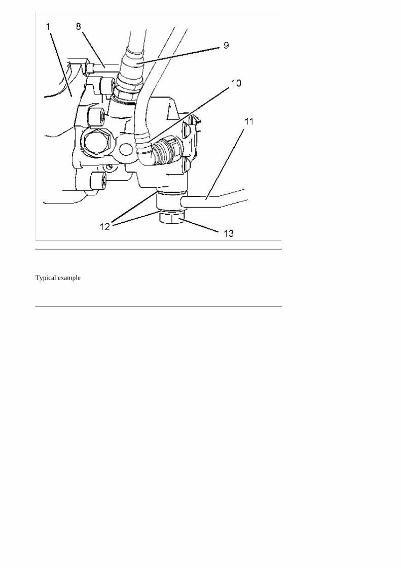
9. Disconnect plastic tube assembly (2) from fuel injection pump (1) .
10. Disconnect harness assembly (6) from solenoid (3). Slide the locking tab into the unlocked position anddisconnect harness assembly (6) from position sensor (7) .
Note: The harness assembly should be positioned in order to avoid an obstruction to the fuel injection pump.
11. Disconnect plastic tube assembly (10) from fuel injection pump (1) .
12. Disconnect plastic tube assembly (9) from fuel injection pump (1) .
13. Disconnect plastic tube assembly (4) from fuel injection pump (1) .
14. Remove banjo bolt (13) and remove sealing washers (12) .
15. Plug or cap all open ports and tube assemblies immediately with new plugs or caps.
Note: Ensure that quick fit connections are clean before the tube assemblies are plugged.
16. Remove fuel injection line (5). Refer to Disassembly and Assembly, "Fuel Injection Lines - Remove". UseTooling (D) in order to plug the open ports in the fuel injection pump and in the fuel manifold. Discard thefuel injection line.
17. Remove tube assembly (8) for the engine oil supply to the fuel injection pump. Remove the banjo bolt andthe sealing washers from the tube assembly.

Typical example
18. Remove bolts (15) and remove bolt (16). Remove support bracket (14) .

Typical example
19. Remove bolts (18) and remove sealing washers (19) .
Note: The fuel injection pump should be supported by hand as the bolts are removed.
20. Carefully remove fuel injection pump (1) from front housing (20). Ensure that Bore (X) in the front housingis not damaged as the fuel injection pump is removed.
21. Remove O-ring seal (17) from fuel injection pump (1) .

Typical example
Note: A new fuel injection pump is supplied, locked in the correct position. Do not unlock the fuelinjection pump before installation.
1. If the fuel injection pump timing has been lost, it is possible to reset the fuel injection pump timing. FollowStep 1.a through Step 1.e in order to reset the fuel injection pump timing.
a. Loosen locking screw (22) and slide spacer (21) to Position (AA). Tighten locking screw (22) to atorque of 9 N·m (80 lb in). This will prevent the locking screw from tightening against the shaft of thefuel injection pump.
The fuel injection pump is now unlocked.
b. Position Tooling (E) onto the shaft of fuel injection pump (1). Align the lever of Tooling (E) withKeyway (Y) and engage the lever into the keyway.

Note: The lever of Tooling (E) should be a close fit in the keyway. If the lever is a loose fit in thekeyway, it is not possible to reset the fuel injection pump timing.
c. Rotate the shaft of the fuel injection pump and engage the pin of Tooling (E) into Hole (Z) .
The fuel injection pump timing is now set in the correct position.
d. Loosen locking screw (22) and slide spacer (21) to Position (BB). Tighten locking screw (22) to atorque of 9 N·m (80 lb in). The locking screw is now tightened against the shaft of the fuel injectionpump.
The fuel injection pump is now locked.
e. Remove Tooling (E) .
Typical example
2. Inspect Bore (X) in front housing (20) for damage. If the bore is damaged, replace the front housing. Referto Disassembly and Assembly, "Housing (Front) - Remove" and Disassembly and Assembly, "Housing(Front) - Install".
3. Use Tooling (F) to lubricate a new O-ring seal (17). Install the O-ring seal onto fuel injection pump (1) .
4. Align fuel injection pump (1) with front housing (20). Carefully install the fuel injection pump to the fronthousing.
Note: The fuel injection pump should be supported by hand until the bolts are installed.

5. Install bolts (18) and new sealing washers (19). Tighten the bolts to a torque of 25 N·m (18 lb ft).
6. If necessary, use Tooling (A) in order to rotate the crankshaft so that number one piston is at top dead centeron the compression stroke. Refer to System Operation, Testing and Adjusting, "Finding Top Centre Positionfor No.1 Piston".
7. Use Tooling (B) in order to lock the camshaft in the correct position. Use Tooling (C) in order to lock thecrankshaft in the correct position. Refer to Disassembly and Assembly, "Gear Group (Front) - Remove andInstall" for the correct procedure.
8. Install the fuel injection pump gear to the fuel injection pump. Refer to Disassembly and Assembly, "FuelInjection Pump Gear - Install" and refer to Disassembly and Assembly, "Gear Group (Front) - Install".
Note: Ensure that the fuel injection pump is unlocked after the installation of fuel injection pump gear iscompleted.
9. Install the front cover. Refer to Disassembly and Assembly, "Front Cover - Remove and Install".
Typical example
10. Position support bracket (14) and install bolts (15) finger tight. Install bolt (16) finger tight.
11. Tighten bolt (16) to a torque of 44 N·m (32.5 lb ft). Tighten bolts (15) to a torque of 22 N·m (16 lb ft).
Typical example

Typical example
12. Install the banjo bolt and new sealing washers to tube assembly (8). Install tube assembly (8) for the oil feedto the fuel injection pump. Tighten the banjo bolt and the nut to a torque of 15 N·m (11 lb ft).
13. Install a new fuel injection line (5). Refer to Disassembly and Assembly, "Fuel Injection Lines - Install".
14. Install new sealing washers (12) and banjo bolt (13) to tube assembly (11). Tighten the banjo bolt to a torqueof 21 N·m (15 lb ft).
15. Connect plastic tube assembly (4) to fuel injection pump (1) .
16. Connect plastic tube assembly (9) to fuel injection pump (1) .
17. Connect plastic tube assembly (10) to fuel injection pump (1) .
18. Connect harness assembly (6) to solenoid (3). Connect harness assembly (6) to position sensor (7). Slide thelocking tab into the locked position.
19. Connect plastic tube assembly (2) to fuel injection pump (1) .

20. If necessary, install the crankcase breather. Refer to Disassembly and Assembly, "Crankcase Breather -Remove and Install".
21. If necessary, install the fuel priming pump. Refer to Disassembly and Assembly, "Fuel Priming Pump -Remove and Install".
22. If necessary, install the fuel filter base. Refer to Disassembly and Assembly, "Fuel Filter Base - Remove andInstall".
23. Turn the battery disconnect switch to the ON position.
24. Turn the fuel supply to the ON position.
25. Remove the air from the fuel system. Refer to Operation and Maintenance Manual, "Fuel System - Prime"for more information.

Fuel Injection Pump Gear - Install
Installation Procedure
Table 1
Required Tools
Tool Part Number Part Description Qty
B 230-6284 Timing Pin (Camshaft) 1
C 230-6283 Timing Pin (Crankshaft) 1
E
9U-7324 Indicator Bracket 1
7H-1942 Dial Indicator 1
3S-3268 Indicator Contact Point 1
7H-1940 Universal Attachment 1
NOTICE
Keep all parts clean from contaminants.
Contaminants may cause rapid wear and shortened component life.
Note: The fuel injection pump must remain locked until the procedure instructs you to unlock the fuel injectionpump.
1. Ensure that number one piston is at the top center position on the compression stroke. Refer to SystemsOperation, Testing and Adjusting, "Finding Top Center Position for No. 1 Piston".

Illustration 1
Typical example
2. Ensure that Tooling (C) is installed in Hole (Y) in the front housing. Use Tooling (C) in order to lock thecrankshaft in the correct position.
3. Ensure that Tooling (B) is installed into Hole (X) in camshaft gear (1) .
4. Ensure that shaft (8) on the fuel injection pump is clean, dry and free from damage.
5. Ensure that the fuel injection pump is locked in the correct position. Refer to Disassembly and Assembly,"Fuel Injection Pump - Install".
6. Ensure that the fuel pump gear is clean, dry and free from wear or damage. If necessary, replace the fuelpump gear.

7. Install fuel pump gear (2) to shaft (8) of the fuel injection pump. Ensure that the timing marks on gear (2)and gear (7) are in alignment and that the mesh of the gears is correct.
Typical example
Typical example
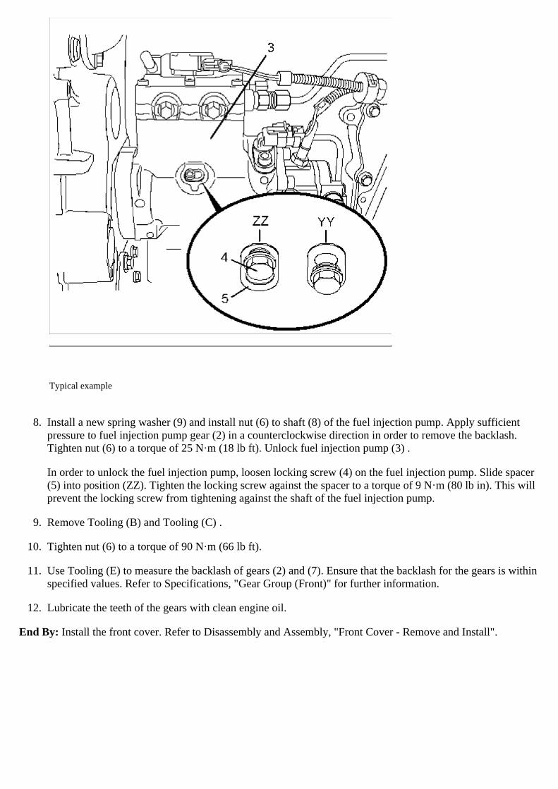
8. Install a new spring washer (9) and install nut (6) to shaft (8) of the fuel injection pump. Apply sufficientpressure to fuel injection pump gear (2) in a counterclockwise direction in order to remove the backlash.Tighten nut (6) to a torque of 25 N·m (18 lb ft). Unlock fuel injection pump (3) .
In order to unlock the fuel injection pump, loosen locking screw (4) on the fuel injection pump. Slide spacer(5) into position (ZZ). Tighten the locking screw against the spacer to a torque of 9 N·m (80 lb in). This willprevent the locking screw from tightening against the shaft of the fuel injection pump.
9. Remove Tooling (B) and Tooling (C) .
10. Tighten nut (6) to a torque of 90 N·m (66 lb ft).
11. Use Tooling (E) to measure the backlash of gears (2) and (7). Ensure that the backlash for the gears is withinspecified values. Refer to Specifications, "Gear Group (Front)" for further information.
12. Lubricate the teeth of the gears with clean engine oil.
End By: Install the front cover. Refer to Disassembly and Assembly, "Front Cover - Remove and Install".