fuel fired booster heater - freel2.com - index fired booster... · fuel fired booster heater...
TRANSCRIPT

Fuel Fired Booster Heater
COMPONENT LOCATION - VEHICLES WITHOUT FFBH REMOTE CONTROL
COMPONENT LOCATION - VEHICLES FROM 2009MY WITH FFBH REMOTE CONTROL
Published: May 21, 2008
Item Part Number Description1 Automatic Temperature Control (ATC) module2 Fuel Fired Booster Heater (FFBH)3 Auxiliary coolant pump4 Ambient air temperature sensor5 Auxiliary fuel pump
Page 1 of 15Contents Page
11/10/2008http://www.landrovertechinfo.com/extlrprod/xml/parsexml.jsp?XMLFile=G852006&...

OVERVIEW
The Fuel fired Booster Heater (FFBH) is rated at 5 kW and compensates for the relatively low coolant temperatures inherent in the diesel engine. The unit is located behind the Right Hand (RH) front fender splash shield and heats engine coolant downstream of the heater core. Operation of the FFBH is controlled by the Automatic Temperature Control (ATC) module via the medium speed Controller Area Network (CAN) bus. Operation of the FFBH is influenced by:
Ambient air temperature Engine coolant temperature.
The FFBH will operate if the ambient air temperature is lower than 5 °C (41 °F) and stop if ambient temperature reaches 8 °C (46 °F). Operation of the FFBH may also be inhibited if the fuel level drops below a predetermined level.
Remote Operation - Vehicles from 2009MY
Item Part Number Description1 Automatic Temperature Control (ATC) module2 Fuel Fired Booster Heater (FFBH)3 Auxiliary coolant pump4 Ambient air temperature sensor5 Auxiliary fuel pump6 FFBH Receiver7 FFBH antenna matching unit
Page 2 of 15Contents Page
11/10/2008http://www.landrovertechinfo.com/extlrprod/xml/parsexml.jsp?XMLFile=G852006&...

On vehicles from 2009MY the FFBH has remote operation. The remote system includes the addition of a FFBH receiver, FFBH antenna matching unit and a remote handset for operation of the system. The FFBH unit remains as previously fitted but has upgraded software. The Engine Control Module (ECM) also has a software calibration upgrade. The instrument cluster message center displays FFBH messages when required.
AUTOMATIC TEMPERATURE CONTROL MODULE
The ATC module is mounted in the center console and is integral with the control panel. The module works in conjunction with the ECM to control all aspects of heating, ventilation, and Air Conditioning (A/C). For additional information, refer to Control Components (412-01 Climate Control)
AUXILIARY FUEL PUMP
Item Part Number Description1 Fuel line connector2 Non return valve3 Solenoid coil4 Plunger5 Filter insert6 Fuel line connector7 O-ring seal8 Spring9 Piston
Page 3 of 15Contents Page
11/10/2008http://www.landrovertechinfo.com/extlrprod/xml/parsexml.jsp?XMLFile=G852006&...

The auxiliary fuel pump is mounted on the RH side of the fuel tank and regulates the fuel supply to the FFBH. The pump is a self priming, solenoid operated plunger pump, controlled by a Pulse Width Modulation (PWM) signal from the control module in the FFBH. When the pump is de-energized, it provides a positive shut-off of the fuel supply. The solenoid coil of the auxiliary fuel pump is installed around a housing which contains a plunger and piston. The piston locates in a bush, and a spring is installed on the piston between the bush and the plunger. A filter insert and a fuel line connector are installed in the inlet end of the housing. A non return valve and a fuel line connector are installed in the fuel outlet end of the housing. While the solenoid coil is de-energized, the spring holds the piston and plunger in the closed position at the inlet end of the housing. An O-ring seal on the plunger provides a fuel tight seal between the plunger and the filter insert, preventing any flow through the pump. When the solenoid coil is energized, the piston and plunger move towards the outlet end of the housing, until the plunger contacts the bush; fuel is then drawn in through the inlet connection and filter. The initial movement of the piston also closes transverse drillings in the bush and isolates the pumping chamber at the outlet end of the housing. Subsequent movement of the piston then forces fuel from the pumping chamber through the non return valve and into the line to the fuel fired booster heater. When the solenoid de-energizes, the spring moves the piston and plunger back towards the closed position. As the piston and plunger move towards the closed position, fuel flows past the plunger and through the annular gaps and transverse holes in the bush to replenish the pumping chamber.
FUEL FIRED BOOSTER HEATER (FFBH)
The FFBH is installed in the coolant supply line to the heater assembly and is located behind the RH front fender splash shield. Two electrical connectors connect the FFBH to the vehicle wiring. The FFBH comprises the following:
A combustion air fan A burner housing A heat exchanger An air inlet hose and muffler An exhaust pipe and muffler A control module.
Sectioned View of Typical Fuel Fired Booster Heater
10 Bush
Page 4 of 15Contents Page
11/10/2008http://www.landrovertechinfo.com/extlrprod/xml/parsexml.jsp?XMLFile=G852006&...

Combustion Air Fan
The combustion air fan regulates the flow of air into the FFBH to support combustion of the fuel supplied by the auxiliary fuel pump. It is also used to purge and cool the FFBH.
Burner Housing
The burner housing contains the burner insert and also incorporates connections for the exhaust pipe, the coolant inlet from the auxiliary coolant pump and the coolant outlet to the vehicle heater. The burner insert incorporates the fuel combustion chamber, an evaporator and a glow pin and flame sensor. Fuel from the auxiliary fuel pump is supplied to a venturi, where it evaporates and enters the combustion chamber to mix with air from the combustion air fan. The glow pin and flame sensor provides the ignition source for the fuel:air mixture and, once combustion is established, monitors the flame.
Heat Exchanger
The heat exchanger transfers heat generated by combustion to the coolant. Two sensors are installed in the heat exchanger casing to provide the control module with inputs of Engine Coolant Temperature (ECT). The control module uses the temperature inputs to control system operation.
Air Inlet Hose and Muffler
Item Part Number Description1 Combustion air fan2 Coolant outlet3 Coolant inlet4 Burner insert5 Heat exchanger6 Temperature sensor7 Exhaust8 Fuel inlet9 Evaporator10 Air inlet
Page 5 of 15Contents Page
11/10/2008http://www.landrovertechinfo.com/extlrprod/xml/parsexml.jsp?XMLFile=G852006&...

A canister type muffler is included in the air inlet supply line. The muffler reduces the noise caused by induction roar.
Exhaust Pipe and Muffler
The exhaust pipe and muffler directs exhaust combustion gases to atmosphere below the front RH wheel arch. Exhaust vapor may be visible when the FFBH is running, depending on atmospheric conditions.
Control Module
The control module controls and monitors operation of the FFBH system. An internal flow of air from the combustion air fan ventilates the control module to prevent it overheating. The control module is powered by a permanent feed from the Battery Junction Box (BJB), and communicates with the ATC module over the medium speed Controller Area Network (CAN) bus.
AUXILIARY COOLANT PUMP
The auxiliary coolant pump is mounted on the heater casing and is used to assist coolant flow through the FFBH and the heater core. The auxiliary coolant pump runs continuously while the FFBH is active. When the FFBH is inactive, coolant flow is reliant on the engine coolant pump. Operation of the auxiliary coolant pump is controlled by a power feed direct from the control module within the FFBH.
AMBIENT AIR TEMPERATURE SENSOR
The ambient air temperature sensor is a Negative Temperature Co-efficient (NTC) thermistor, and is mounted in the
Page 6 of 15Contents Page
11/10/2008http://www.landrovertechinfo.com/extlrprod/xml/parsexml.jsp?XMLFile=G852006&...

Left Hand (LH) door mirror. The sensor is connected to the Engine Control Module (ECM) which transmits an ambient air temperature value over the high speed CAN bus. This value is relayed to the ATC module by the Central Junction Box (CJB) over the medium speed CAN bus. For additional information, refer to Control Components (412-01 Climate Control)
REMOTE CONTROL COMPONENTS - VEHICLES FROM 2009MY WITH FFBH REMOTE CONTROL
The addition of remote control retains the FFBH components fitted to pre 2009MY vehicles with the addition of the following components:
FFBH with upgraded software and calibration FFBH remote handset FFBH remote receiver Receiver power, communication and antenna harnesses Antenna matching unit harness to connect receiver co-axial cable to existing DAB antenna in side window.
FFBH Remote Handset
The remote handset allows the driver to remotely activate the FFBH without entering the vehicle. The handset has a range of at least 100 m (328 ft) in free space, although this distance may be decreased depending on the location of obstacles such as buildings. The handset is powered by a 3.3 volt CR1/3N replaceable battery which can be accessed by removing a cover from the rear of the handset. The battery life in the remote handset is approximately 300 FFBH cycles. One cycle is defined as a handset button press followed by 30-minute burn time with flashing LED feedback. The remote handset has a green Light Emitting Diode (LED) to indicate the FFBH is active. When the 'ON' button is pressed on the handset for more than 2 seconds, the LED will illuminate for 2 seconds. After the 2 second period has passed, the LED will illuminate for 50 ms every 2 seconds for up to the 30 minute on time of the FFBH. The LED will only stop flashing if the 'OFF' button is pressed or the 30 minute on timer has elapsed.
Remote Handset LED Indicator Functionality
The LED illuminates in different ways to alert the driver to the various states of the FFBH remote control system as follows:
Illuminates green for 2 seconds when the ON button has been pressed to show that the receiver unit has successfully received the handset on request. The FFBH may now start operating providing that fuel level, battery voltage and coolant temperature variables are within limits. Flashes green for 50 ms every 2 seconds to indicate that the FFBH may be active. Illuminates red for 2 seconds when the OFF button has been pressed to show that the receiver unit has successfully received the handset off request. The FFBH should then stop operating.
Item Part Number Description1 On button2 Off button3 LED operation indicator4 Antenna
Page 7 of 15Contents Page
11/10/2008http://www.landrovertechinfo.com/extlrprod/xml/parsexml.jsp?XMLFile=G852006&...
Flashes green or red for 2 seconds when pressing the ON or OFF buttons to indicate that the signal was not received by the FFBH receiver Illuminates orange before changing to green or red to show that remote handset battery voltage is low Flashes orange for 5 seconds to show that signal was not received by the FFBH and that the remote handset battery requires replacement.
Remote Handset Pairing
Each remote handset must be 'paired' to the receiver to enable communications. Each handset has a unique identification number which is stored by the receiver. The receiver can store up 3 handset identification numbers. If a fourth handset is paired to the receiver, the receiver will replace the first paired handset number with that for the fourth handset in the receiver memory. Subsequently, the first paired handset will no longer be paired and will not be recognised by the receiver. The following procedure details the pairing process:
Remove fuse FA5 from the Rear Junction Box (RJB) Wait for a minimum of 5 seconds Replace fuse to position FA5 in the RJB Within 5 seconds of replacing the fuse (and restoring the receiver power supply), press and hold the remote handset OFF button Confirmation of successful pairing is displayed by the remote handset LED illuminating in a red color for 2 seconds.
NOTE:
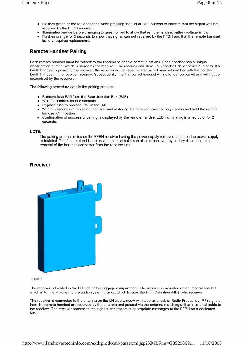
Receiver
The receiver is located in the LH side of the luggage compartment. The receiver is mounted on an integral bracket which in turn is attached to the audio system bracket which locates the High Definition (HD) radio receiver. The receiver is connected to the antenna on the LH side window with a co-axial cable. Radio Frequency (RF) signals from the remote handset are received by the antenna and passed via the antenna matching unit and co-axial cable to the receiver. The receiver processes the signals and transmits appropriate messages to the FFBH on a dedicated bus.
The pairing process relies on the FFBH receiver having the power supply removed and then the power supply re-instated. The fuse method is the easiest method but it can also be achieved by battery disconnection or removal of the harness connector from the receiver unit.
Page 8 of 15Contents Page
11/10/2008http://www.landrovertechinfo.com/extlrprod/xml/parsexml.jsp?XMLFile=G852006&...

Antenna and Antenna Matching Unit
Antenna Matching Unit
The FFBH antenna is located in the LH rear side window and uses the same antenna elements as used by the audio Digital Audio Broadcast (DAB) system. Situated above the DAB antenna unit, behind the headlining, is an antenna matching unit. A flying lead from this unit connects directly to a stud on the glass antenna. The receiver unit connects to the matching unit via a co-axial cable. The glass mounted antenna receives RF transmitted signals from the remote handset and transmits them, via the matching unit and co-axial cable, to the FFBH receiver.
CONTROL DIAGRAM - VEHICLES WITHOUT FFBH REMOTE CONTROL
NOTE:
A = Hardwired; D = High speed CAN bus; N = Medium speed CAN bus
Page 9 of 15Contents Page
11/10/2008http://www.landrovertechinfo.com/extlrprod/xml/parsexml.jsp?XMLFile=G852006&...

CONTROL DIAGRAM - VEHICLES FROM 2009MY WITH FFBH REMOTE CONTROL
Item Part Number Description1 Battery2 Fuse 17, BJB3 Fuse 27, CJB4 ATC module 5 CJB6 Engine Control Module (ECM)7 Ambient air temperature sensor8 Auxiliary coolant pump9 Auxiliary fuel pump10 Fuel fired booster heater11 Fuse 32, BJB
Page 10 of 15Contents Page
11/10/2008http://www.landrovertechinfo.com/extlrprod/xml/parsexml.jsp?XMLFile=G852006&...

NOTE:
A = Hardwired; D = High speed CAN bus; F = RF Transmission; N = Medium speed CAN bus; T = Co-axial; AA = Webasto 'W' bus
Item Part Number Description1 Battery2 Fuse 17, BJB3 Fuse 27, CJB4 ATC module 5 CJB6 Engine Control Module (ECM)7 Ambient air temperature sensor8 Auxiliary fuel pump9 Auxiliary coolant pump10 FFBH Receiver (Vehicles from 2009MY)
Page 11 of 15Contents Page
11/10/2008http://www.landrovertechinfo.com/extlrprod/xml/parsexml.jsp?XMLFile=G852006&...

PRINCIPLES OF OPERATION
If a heating request is received and the ambient air temperature is less than or equal to 5°C (41 °F), the ATC module transmits a 'supplemental heat' message to the FFBH control module over the medium speed CAN bus. The control module responds by returning a 'supplemental heat' status message back to the ATC module. The control module will now initiate the FFBH start sequence. If the heating request is removed, or ambient air temperature rises to 8°C (46 °F), the ATC module transmits a 'heater off' message to the FFBH control module over the medium speed CAN bus. Again, the control module responds by returning a 'heater off' status message back to the ATC module. The control module will now de-activate the FFBH. If maximum heating is requested, Engine Coolant Temperature (ECT) becomes the overriding factor. In this instance, the ATC module will change the CAN bus message from 'heater off' to 'supplemental heat' when ECT is below or equal to 70°C (158°F). If ECT rises to 78°C (172°F) the ATC module returns the message to 'heater off'. The control module will not start the FFBH, or will discontinue operation, if any of the following occur:
The control module is in the error lockout mode (see Diagnostics, below). The engine is not running, or stops running for approximately 4 seconds. The time delay is included for stall detection. A 'fuel cut-off' message is received from the CJB over the medium speed CAN bus. For additional information, refer to Air Bag and Safety Belt Pretensioner Supplemental Restraint System (SRS) (501-20 Supplemental Restraint System) A low fuel level message is received from the CJB over the medium speed CAN bus (see table below). For additional information, refer to Instrument Cluster (413-01 Instrument Cluster)
The control module will control FFBH operation based on the following levels of fuel in the tank.
Start Sequence
At the beginning of a start sequence, the FFBH control module;
energizes the glow pin and flame sensor to pre heat the combustion chamber starts the combustion air fan at slow speed and energizes the auxiliary coolant pump.
After approximately 30 seconds, the control module energizes the auxiliary fuel pump at the starting sequence speed. The fuel delivered by the auxiliary fuel pump evaporates in the combustion chamber, mixes with air from the combustion air fan and is ignited by the glow pin and flame sensor. The control module then progressively increases the speed of the auxiliary fuel pump and the combustion air fan. Once combustion is established the control module switches the glow pin and flame sensor to the flame sensing function to monitor combustion. From the beginning of the start sequence to stable combustion at full load takes approximately 150 seconds.
Full and Part Load Combustion
While the FFBH is running, the control module cycles the heater between full load combustion, part load combustion and a control idle phase of operation, depending on the temperature of the coolant in the heat exchanger. The heat output level at part load combustion is 2.8 kW. This rises to 5 kW at full load combustion. The control module transmits the amount of fuel used by the FFBH to the instrument cluster, and the FFBH coolant temperature
11 Antenna matching unit12 Fuel fired booster heater13 FFBH/DAB antenna (Vehicles from 2009MY)14 Fuse 32, BJB15 Fuse FA5, RJB16 FFBH Remote handset (Vehicles from 2009MY)
Fuel Level, liters (US Gallons) Description 7.5 (1.98) Start 4.5 (1.18) Stop 10.5 (2.77) Restart
Page 12 of 15Contents Page
11/10/2008http://www.landrovertechinfo.com/extlrprod/xml/parsexml.jsp?XMLFile=G852006&...

to the ATC module.
Switching Point Temperatures
After the start sequence, the control module maintains full load combustion until the coolant temperature reaches switching point temperature 1. At this temperature, the control module decreases the speed of the auxiliary fuel pump and the combustion air fan to half speed, to produce part load combustion. The control module maintains part load combustion while the coolant temperature remains between switching point temperatures 2 and 4. At part load combustion the temperature of the coolant will increase or decrease depending on the amount of heat required to heat the vehicle interior. If the coolant temperature decreases to switching point temperature 4, the control module increases the speed of the auxiliary fuel pump and the combustion air fan to full speed, to return to full load combustion. If the coolant temperature increases to switching point temperature 2, the control module enters a control idle phase of operation. On entering the control idle phase, the control module immediately switches the auxiliary fuel pump off, to stop combustion, and starts a timer for the combustion air fan. After a 2 minute cool down period, the control module switches the combustion air fan off and then remains in the control idle phase while the coolant temperature remains above switching point temperature 3. If the coolant temperature decreases to switching point temperature 3, the control module initiates a start to part load combustion. A start to part load combustion takes approximately 90 seconds. In order to limit the build up of carbon deposits on the glow pin and flame sensor, the control module also enters the control idle phase if continuous combustion time exceeds 72 minutes (at part load, full load or a combination of both). After the cool down period, if the coolant is still in the temperature range that requires additional heat, the control module restarts the fuel fired booster heater.
Shutdown
To stop the FFBH, the control module de-energizes the auxiliary fuel pump to stop combustion, but continues operation of the combustion air fan and the auxiliary coolant pump for a time, to cool down the FFBH. The cool down time is 100 seconds if the FFBH was operating at part load combustion and 175 seconds if the FFBH was operating at full load combustion.
Switching Point Temperature, ºC (ºF) Item Number Description 1 Full load to part load 79ºC (174ºF) 2 Part load to control idle 90ºC (194ºF) 3 Control idle to part load 74ºC (165ºF) 4 Part load to full load 69ºC (156ºF)
Page 13 of 15Contents Page
11/10/2008http://www.landrovertechinfo.com/extlrprod/xml/parsexml.jsp?XMLFile=G852006&...

Diagnostics
The control module monitors the fuel fired booster heater system for faults. Diagnostic Trouble Code's (DTC)'s are stored in a volatile memory in the control module, which can be interrogated by the Land Rover approved diagnostic system via the medium speed CAN bus. The control module also incorporates an error lockout mode of operation that inhibits operation to prevent serious faults from causing further damage to the system. In the error lockout mode, the control module immediately stops the auxiliary fuel pump, and stops the combustion air fan and auxiliary coolant pump after a cool down time of approximately 2 minutes. Error lockout occurs for:
Start failure and flameout: If a start sequence fails to establish combustion, or a flameout occurs after combustion is established, the control module immediately initiates another start sequence. The start failure or flameout is also recorded by an event timer in the control module. The event timer is increased by one after each start failure or flameout, and decreased by one if a subsequent start is successful. If the event timer increases to three (over any number of drive cycles), the control module enters the error lockout mode. Heat exchanger casing overheat: To protect the system from excessive temperatures, the control module enters the error lockout mode if the heat exchanger coolant temperature exceeds 125 °C (257 °F). Battery voltage out of limits: Error lockout will occur if battery voltage falls below 10.25 or rises above 15.5 volts.
The error lockout mode can be cleared using the Land Rover approved diagnostic system, or by disconnecting the battery power supply for a minimum of 10 seconds.
Remote Operation - Vehicles from 2009MY with FFBH Remote Control
The 868.3 MHz Radio Frequency (RF) signals transmitted by the remote handset are received by the DAB/FFBH antenna located in the LH rear side window. The signals received by the antenna are detected by the FFBH receiver. A 'handshake' signal is sent back from the receiver to the handset to confirm a valid on or off request and activate the handset LED accordingly. The receiver processes the signal it received and transmits the appropriate signals via a dedicated bus to the FFBH control module. NOTE:
When the FFBH is activated by the remote handset, the FFBH control module will allow the FFBH to operate for 30 minutes or until an off request is received from the remote handset or CJB. During the 30 minute period, the FFBH may operate in either full load combustion, part load combustion or a controlled idle phase of operation, depending on the temperature of the coolant in the heat exchanger.
Pre-burn Thresholds
The FFBH unit will only activate remotely if the following threshold conditions are met:
Pre-burn battery voltage check: ≥11.5V (voltage at FFBH terminals) Pre-burn coolant temperature check: ≤15°C (internal FFBH measurement) Pre-burn fuel level check: ≥7.5 liters (value stored in FFBH at ignition off)
The fuel level value stored within the FFBH unit is only updated when the engine is running. When starting the FFBH via remote control with the engine off, the fuel level value used in the FFBH calculations will be that stored at the last key off event. It is therefore possible for the FFBH to fail to operate remotely if the engine was stopped with a low fuel level; if the fuel tank is subsequently refuelled, the FFBH stored fuel level will still read low if the engine has not been started since refuelling. If the FFBH does not activate due to low battery voltage or low fuel level, the FFBH control module transmits a message is passed on the medium and high speed CAN buses, via the CJB to the instrument cluster message center which will display one of the following messages at ignition on:
AUXILIARY HEATER UNAVAILABLE LOW FUEL AUXILIARY HEATER UNAVAILABLE LOW BATTERY.
If both low fuel and low battery voltage messages are valid, the instrument cluster message center will alternate between the two messages.
Remote Control ‘Park Heat’ to ATC ‘Supplementary Heat’ Transitions
The ‘handshake’ signal only confirms handset-receiver communications were successful, and not that the FFBH has turned on.
Page 14 of 15Contents Page
11/10/2008http://www.landrovertechinfo.com/extlrprod/xml/parsexml.jsp?XMLFile=G852006&...

NOTE:
If the FFBH has been operated remotely (‘park heat’) and the vehicle is started whilst the FFBH is still active, it will transition into the ATC-controlled ‘supplementary heat’ mode if the ATC requests it. Should the ATC then send a message to the FFBH to turn off, the FFBH will remain active if 30 minutes has not yet elapsed from the original remote control ‘park heat’ request. Once the remainder of 30 minutes has elapsed, the FFBH will turn off.
Switching Point Temperatures
When remotely started the FFBH uses a different set of switching point temperatures to the normal ‘supplemental heat’ mode. This is because the remote start feature can start the FFBH with the engine off – thus different thresholds are required to optimise the heating of the engine coolant.
Switching Point Temperatures
The FFBH can still be activated by the ATC module as previously described
Switching Point Temperature, ºC (ºF) Item Number Description 1 Full load to part load 80ºC (176ºF) 2 Part load to control idle 90ºC (194ºF) 3 Control idle to part load 50ºC (122ºF) 4 Part load to full load 70ºC (158ºF)
Page 15 of 15Contents Page
11/10/2008http://www.landrovertechinfo.com/extlrprod/xml/parsexml.jsp?XMLFile=G852006&...