fuel conversion kit instructions - rg-cloud.com cth2d conversion-orig.pdf · cth2d fuel conversion...
TRANSCRIPT

WARNING
Installation must be done by a contractor qualified
in the installation and service of gas-fired heating
equipment or your gas supplier.
Improper installation, adjustment, alteration, service
or maintenance can result in death, injury or
property damage. Read the Installation, Operation
and Service Manual thoroughly before installing or
servicing this equipment.
Installer
Please take the time to read and understand
these instructions prior to any installation.
Installer must give a copy of this manual to the owner.
Owner
Keep this manual in a safe place in order to provide
your service technician with necessary information.
Roberts-Gordon LLC1250 William StreetP.O. Box 44Buffalo, New York 14240-0044Telephone: +1.716.852.4400Fax: +1.716.852.0854Toll Free: 800.828.7450
www.robertsgordon.com
© 2017 Roberts-Gordon LLC
CTH2D-40CTH2D-60CTH2D-80
CTH2D-100CTH2D-125CTH2D-150CTH2D-175
P/N 236101NA Orig 09/17
Fuel ConversionKit Instructions
WARNING
FOR YOUR SAFETY
If you smell gas: 1. Open windows.
2. DO NOT try to light any appliance.
3. DO NOT use electrical switches.
4. DO NOT use any telephone in
your building.
5. Extinguish any open flame.
6. Leave the building.
7. Immediately call your local gas
supplier after leaving the building.
Follow the gas supplier’s
instructions.
8. If you cannot reach your gas
supplier, call the Fire Department.
Fire Hazard
Keep all flammable objects, liquids and
vapors the minimum required clear-
ances to combustibles away from
heater.
Some objects will catch fire or explode when placed close to heater.
Failure to follow these instructions can result in death, injury or property damage.
Model CTH2D


TABLE OF FIGURES
Figure 1: Conversion Kit Regulator Installation in Valve
(Natural to Propane)................................................... 3
Figure 2: Conversion Kit Regulator Installation in Valve
(Propane to Natural)................................................... 4
Figure 3: Burner Assembly Overview ....................................... 5
Figure 4: Burner (External View)............................................... 6
Figure 5: Burner, Side View (Internal Assembly) ...................... 6
Figure 6: Pressure Regulator................................................... 7
Figure 7: Manometer Reading .................................................. 9
Figure 8: Label P/N 91039400 ................................................ 10
Figure 9: Level Reflector ......................................................... 12
Figure 10: Level Side Reflector ............................................... 12
Figure 11: Two Side Reflectors................................................ 12
Figure 12: 45° Tilt Reflector..................................................... 13
Figure 13: U-Tube, Level Reflector .......................................... 13
Figure 14: U-Tube, 45° ............................................................ 13
Figure 15: U-Tube, Opposite 45° Reflector.............................. 14
Figure 16: 2-Foot Deco Grille, 1-Foot Deco Grille and
Protective Grille ...................................................... 14
Figure 17: Lower Clearance Shield*........................................ 14


© 2017 Roberts-Gordon LLC
All rights reserved. No part of this work covered by the copyrights herein may be reproduced
or copied in any form or by any means - graphic, electronic, or mechanical, including
photocopying, recording, taping or information storage and retrieval systems - without the
written permission of Roberts-Gordon LLC.
TABLE OF CONTENTS
SECTION 1: Heater Safety...................................................... 1
1.1 Manpower Requirements ............................................. 1
SECTION 2: Installer Responsibility ..................................... 2
2.1 Wall Tag ....................................................................... 2
2.2 Corrosive Chemicals.................................................... 2
2.3 National Standards and Applicable Codes .................. 2
SECTION 3: For Natural to Propane Conversions Only....... 3
3.1 Contents of Fuel Conversion Kits (Natural to Propane).......3
SECTION 4: For Propane to Natural Conversions Only....... 4
4.1 Contents of Fuel Conversion Kits (Propane to Natural).......4
SECTION 5: Fuel Conversion Instructions ........................... 5
SECTION 6: Clearances to Combustibles........................... 11
6.1 Required Clearances to Combustibles....................... 11
SECTION 7: Operation and Maintenance............................ 16
7.1 Sequence of Operation .............................................. 16
7.2 To Shut Off Heater...................................................... 16
7.3 To Start Heater ........................................................... 16
7.4 Pre-Season Maintenance and Annual Inspection....... 17
7.5 Maintenance Checklist.........................................................17
SECTION 8: The ROBERTS GORDON® COMPLETETM
CTH2D Warranty............................................... 19
Printed in U.S.A.


SECTION 1: HEATER SAFETY
1
SECTION 1: HEATER SAFETY
Your Safety is Important to Us!
This symbol is used throughout
the manual to notify you of
possible fire, electrical or burn
hazards. Please pay special
attention when reading and
following the warnings in these
sections.
Installation, service and annual inspection of heater
must be done by a contractor qualified in the
installation and service of gas-fired heating
equipment.
Read this manual carefully before installation,
operation or service of this equipment.
Due to the nature of gas conversions, it is important
you use the correct conversion kit for the heater
model and gas you are converting to. Use only
genuine ROBERTS GORDON® conversion kits.
This heater is designed for heating nonresidential
indoor spaces. Do not install in residential spaces.
These instructions, the layout drawing, local codes
and ordinances, and applicable standards that apply
to gas piping, electrical wiring, venting, etc. must be
thoroughly understood before proceeding with the
installation.
Protective gear is to be worn during installation,
operation and service. Thin sheet metal parts, includ-
ing the aluminum reflector portion of the heater and
the various venting components, have sharp edges.
To prevent injury, the use of work gloves is recom-
mended. The use of gloves will also prevent the
transfer of body oils from the hands to the surface of
the reflector.
Before installation, check that the local distribution
conditions, nature of gas and pressure, and adjust-
ment of the appliance are compatible.
This heater must be applied and operated under the
general concepts of reasonable use and installed
using best building practices.
This appliance is not intended for use by persons
(including children) with reduced physical, sensory or
mental capabilities, or lack of experience and
knowledge, unless they have been given supervision
or instruction concerning use of the appliance by a
person responsible for their safety. Children should
be supervised to ensure that they do no play with the
appliance.
For additional copies of the Installation, Operation
and Service Manual, please contact Roberts-Gordon
LLC.
1.1 Manpower Requirements
To prevent personal injury and damage to the heater,
two persons will be required for installation.
CTH2D FUEL CONVERSION INSTRUCTIONS
2
SECTION 2: INSTALLER RESPONSIBILITY
The installer is responsible for the following:
• To install the heater, as well as the gas and electri-
cal supplies, in accordance with applicable specifi-
cations and codes. Roberts-Gordon recommends
the installer contact a local Building Inspector or
Fire Marshal for guidance.
• To use the information given in a layout drawing
and in the manual together with the cited codes
and regulations to perform the installation.
• To install the heater in accordance with the
clearances to combustibles.
• To furnish all needed materials not furnished as
standard equipment.
• To plan location of supports.
• To provide access to burners for servicing on all
sides for burner removal.
• To provide the owner with a copy of this installa-
tion, operation and service manual.
• To never use heater as support for a ladder or
other access equipment and never hang or sus-
pend anything from heater.
• To ensure there is adequate air circulation around
the heater and to supply air for combustion, venti-
lation and distribution in accordance with local
codes.
• To safely and adequately install heater using
materials with a minimal working load of 75 lbs
(33 kg).
• To ensure the heater is placed in a approved
application.
2.1 Wall Tag
A laminated wall tag is available for the heater as a
permanent reminder of the safety instructions and
the importance of the required clearances to com-
bustibles. Please contact Roberts-Gordon or your
ROBERTS GORDON® independent distributor to
obtain the wall tag. Affix the tag by peeling off the
backing of the adhesive strips on the rear surface
and position the tag on a wall near the heater (e.g.
thermostat or ROBERTS GORDON® Controller).
A copy of the wall tag (P/N 91037912) is illustrated on
the back cover. For an immediate solution, you may
affix this copy on the wall near the heater.
Know your model number and installed configuration.
Model number and installed configuration are found
on the burner and in the Installation, Operation and
Service Manual. Write the proper clearance dimen-
sions in permanent ink according to your model num-
ber and configuration in the open spaces on the tag.
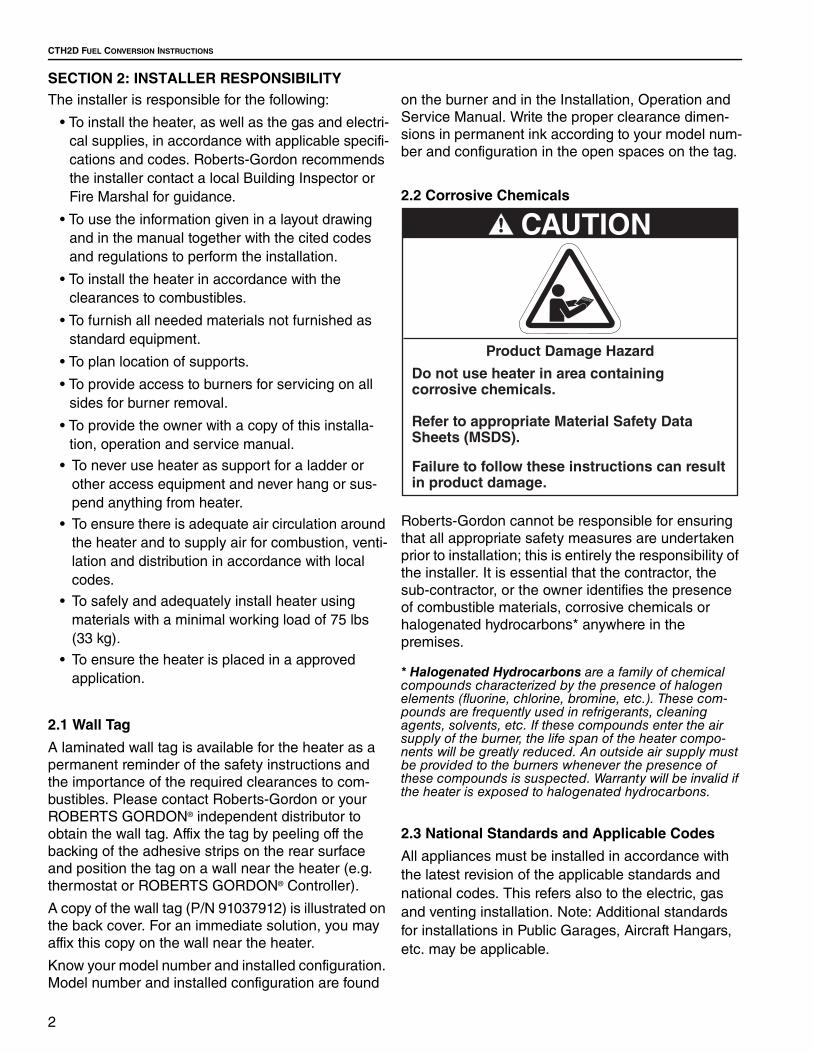
2.2 Corrosive Chemicals
Roberts-Gordon cannot be responsible for ensuring
that all appropriate safety measures are undertaken
prior to installation; this is entirely the responsibility of
the installer. It is essential that the contractor, the
sub-contractor, or the owner identifies the presence
of combustible materials, corrosive chemicals or
halogenated hydrocarbons* anywhere in the
premises.
* Halogenated Hydrocarbons are a family of chemical compounds characterized by the presence of halogen elements (fluorine, chlorine, bromine, etc.). These com-pounds are frequently used in refrigerants, cleaning agents, solvents, etc. If these compounds enter the air supply of the burner, the life span of the heater compo-nents will be greatly reduced. An outside air supply must be provided to the burners whenever the presence of these compounds is suspected. Warranty will be invalid if the heater is exposed to halogenated hydrocarbons.
2.3 National Standards and Applicable Codes
All appliances must be installed in accordance with
the latest revision of the applicable standards and
national codes. This refers also to the electric, gas
and venting installation. Note: Additional standards
for installations in Public Garages, Aircraft Hangars,
etc. may be applicable.
CAUTION
Product Damage Hazard
Do not use heater in area containing corrosive chemicals.
Refer to appropriate Material Safety Data Sheets (MSDS).
Failure to follow these instructions can result in product damage.
SECTION 3: FOR NATURAL TO PROPANE CONVERSIONS ONLY
3
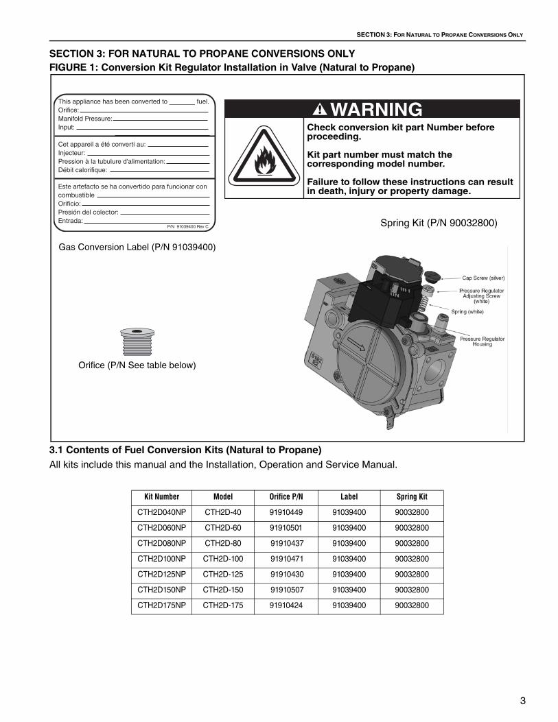
SECTION 3: FOR NATURAL TO PROPANE CONVERSIONS ONLY
FIGURE 1: Conversion Kit Regulator Installation in Valve (Natural to Propane)
3.1 Contents of Fuel Conversion Kits (Natural to Propane)
All kits include this manual and the Installation, Operation and Service Manual.
Spring Kit (P/N 90032800)
Gas Conversion Label (P/N 91039400)
Orifice (P/N See table below)
Kit Number Model Orifice P/N Label Spring Kit
CTH2D040NP CTH2D-40 91910449 91039400 90032800
CTH2D060NP CTH2D-60 91910501 91039400 90032800
CTH2D080NP CTH2D-80 91910437 91039400 90032800
CTH2D100NP CTH2D-100 91910471 91039400 90032800
CTH2D125NP CTH2D-125 91910430 91039400 90032800
CTH2D150NP CTH2D-150 91910507 91039400 90032800
CTH2D175NP CTH2D-175 91910424 91039400 90032800

CTH2D FUEL CONVERSION INSTRUCTIONS
4
SECTION 4: FOR PROPANE TO NATURAL CONVERSIONS ONLY
FIGURE 2: Conversion Kit Regulator Installation in Valve (Propane to Natural)
4.1 Contents of Fuel Conversion Kits (Propane to Natural)
All kits include this manual and the Installation, Operation and Service Manual.
Spring Kit (P/N 90032900)
Gas Conversion Label (P/N 91039400)
Orifice: (P/N See table below)
Kit Number Model Orifice P/N Label Spring Kit
CTH2D040PN CTH2D-40 91910432 91039400 90032900
CTH2D060PN CTH2D-60 91910425 91039400 90032900
CTH2D080PN CTH2D-80 91910418 91039400 90032900
CTH2D100PN CTH2D-100 91910412 91039400 90032900
CTH2D125PN CTH2D-125 91910405 91039400 90032900
CTH2D150PN CTH2D-150 91910401 91039400 90032900
CTH2D175PN CTH2D-175 91910406 91039400 90032900

SECTION 5: FUEL CONVERSION INSTRUCTIONS
5
SECTION 5: FUEL CONVERSION INSTRUCTIONS
Step 5.1 Burner Removal
1. Turn off gas supply valve, disconnect gas from
burner.
2. Turn off power supply and disconnect wires from
burner.
3. Unplug thermostat wires from burner.
4. If outside air is installed, disconnect.
5. Remove the nuts which hold the burner on the
transition tube using a 1/2" wrench.
6. Remove the burner. See Figure 3.
7. Save the gasket (P/N 92700025) or re-install a
new one after conversion.
FIGURE 3: Burner Assembly Overview
WARNING
Severe Injury Hazard
Secure burner to burner tube with nuts and lockwashers.
Hang heater with materials with a minimum working load of 75 lbs (33 kg).
Failure to follow these instructions can result in death, injury or property damage.

CTH2D FUEL CONVERSION INSTRUCTIONS
6
FIGURE 4: Burner (External View)
FIGURE 5: Burner, Side View (Internal Assembly)

SECTION 5: FUEL CONVERSION INSTRUCTIONS
7
Step 5.2 Burner Cup Assembly Removal
1. Remove the burner cup assembly: Remove
electrode and flame sense wires from compo-
nents and unscrew the burner cup. See Page 6, Figure 5.
2. Remove and replace the gas orifice: Use a 1/2"
open end wrench (spanner) to remove the
orifice. Apply a small amount of pipe sealant to
the threads of the replacement orifice. Be aware
that over application of sealant may cause
blockage of the orifice. Insert and tighten the
replacement orifice.
CAUTION: Do not over-tighten the orifice. The
torque value for the orifice is 15 in/lbs; contact
your factory representative for more details.
Step 5.3 Burner Cup Assembly Replacement
1. Be sure gas supply to heater is off.
2. Replace the burner cup and wire connections.
3. Open the control side door: Using your thumb
and forefinger, remove the two thumb screws
and take door off. See Page 6, Figure 4.
4. Replace the regulator spring. Using a flat head
screwdriver, remove the cap from the regulator
adjusting screw, remove the screw and remove
and replace the spring. NOTE: Silver spring for
Natural, white spring for Propane. See Page 3, Section 3 and Page 4, Section 4 to verify spring
kit components.
5. Replace the adjusting screw and turn down
approximately 1/2".
FIGURE 6: Pressure Regulator
6. If the burner is removed, re-install the gasket
and the burner on the transition tube by
inserting lockwashers and bolts, torque to 120
in/lbs. Reconnect outside air, gas and electrical
supplies. For proper installation procedures, see
venting, gas piping and electrical sections of the
Installation, Operation and Service Manual
included in this Conversion Kit.
Step 5.4 Adjust Regulator
1. Using a 3/32" hex key, remove the plug at the
valve outlet and install a hose. Connect the hose
to a liquid filled manometer. See Page 9, Figure 7.
2. Turn on gas and power. Turn up thermostat.
3. When unit comes on, adjust the regulator by
turning the adjusting screw to set the pressure
to:
Natural: 3.5" wc
Propane: 10.5" wc
4. Turn off power and gas.
5. Remove hose and replace plug at valve outlet.
Replace O Ring and cap screw.
Step 5.5 Inlet Gas Pressure Checks
The gas inlet pressure to the heater must be checked
as follows:
1. Turn off electrical supply to heater.
2. Turn off gas supply to heater.
3. Remove the plug at the valve inlet and install a
hose. Connect the hose to a liquid filled
WARNING
Severe Injury Hazard
Secure burner to burner tube with nuts and lockwashers.
Hang heater with materials with a minimum working load of 75 lbs (33 kg).
Failure to follow these instructions can result in death, injury or property damage.

CTH2D FUEL CONVERSION INSTRUCTIONS
8
manometer. See Page 9, Figure 7.
4. Turn on gas supply to heater.
5. The manometer should read a maximum gas
pressure of 14.0" wc for Natural or L.P. gas.
6. Turn on electrical supply to heater.
7. With heater in operation, manometer should
read a minimum inlet pressure of 4.5" wc for
Natural gas or 11.0" wc for L.P. gas.
8. If in steps 5 and 7, the recommended maximum
and minimum pressures are not obtained, the
main gas supply pressure to the heater must be
adjusted as necessary for compliance.
9. Turn off main gas supply to heater.
10.Turn off electrical supply to heater.
11. Remove manometer and insert pipe plug into
valve inlet.
12.Turn on main gas supply to heater.
13.Leak test plug in tapping using soap solution.
14.Turn on electrical supply to heater.

SECTION 5: FUEL CONVERSION INSTRUCTIONS
9
FIGURE 7: Manometer Reading
Inlet Test Port
Outlet Test Port
DANGER
Electrical Shock Hazard
Disconnect electric before service.
Appliance must be properly grounded.
Failure to follow these instructions can result in death or electrical shock.
CTH2D FUEL CONVERSION INSTRUCTIONS
10
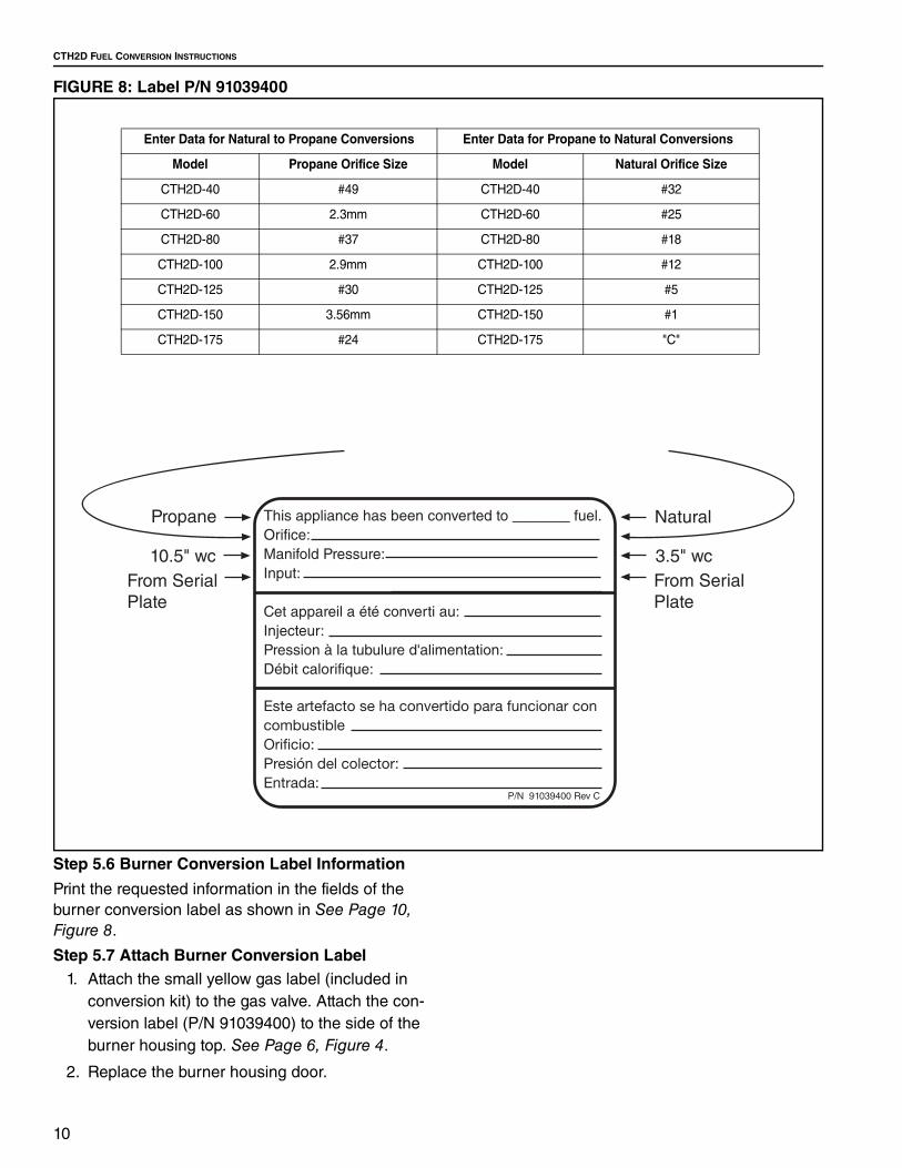
FIGURE 8: Label P/N 91039400
Step 5.6 Burner Conversion Label Information
Print the requested information in the fields of the
burner conversion label as shown in See Page 10, Figure 8.
Step 5.7 Attach Burner Conversion Label
1. Attach the small yellow gas label (included in
conversion kit) to the gas valve. Attach the con-
version label (P/N 91039400) to the side of the
burner housing top. See Page 6, Figure 4.
2. Replace the burner housing door.
Enter Data for Natural to Propane Conversions Enter Data for Propane to Natural Conversions
Model Propane Orifice Size Model Natural Orifice Size
CTH2D-40 #49 CTH2D-40 #32
CTH2D-60 2.3mm CTH2D-60 #25
CTH2D-80 #37 CTH2D-80 #18
CTH2D-100 2.9mm CTH2D-100 #12
CTH2D-125 #30 CTH2D-125 #5
CTH2D-150 3.56mm CTH2D-150 #1
CTH2D-175 #24 CTH2D-175 "C"
SECTION 6: CLEARANCES TO COMBUSTIBLES
11
SECTION 6: CLEARANCES TO COMBUSTIBLES
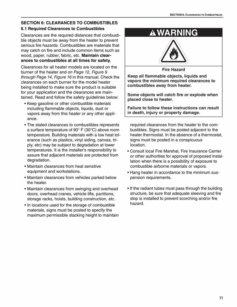
6.1 Required Clearances to Combustibles
Clearances are the required distances that combusti-
ble objects must be away from the heater to prevent
serious fire hazards. Combustibles are materials that
may catch on fire and include common items such as
wood, paper, rubber, fabric, etc. Maintain clear-
ances to combustibles at all times for safety.
Clearances for all heater models are located on the
burner of the heater and on Page 12, Figure 9
through Page 14, Figure 16 in this manual. Check the
clearances on each burner for the model heater
being installed to make sure the product is suitable
for your application and the clearances are main-
tained. Read and follow the safety guidelines below:
• Keep gasoline or other combustible materials
including flammable objects, liquids, dust or
vapors away from this heater or any other appli-
ance.
• The stated clearances to combustibles represents
a surface temperature of 90° F (30°C) above room
temperature. Building materials with a low heat tol-
erance (such as plastics, vinyl siding, canvas, tri-
ply, etc) may be subject to degradation at lower
temperatures. It is the installer’s responsibility to
assure that adjacent materials are protected from
degradation.
• Maintain clearances from heat sensitive
equipment and workstations.
• Maintain clearances from vehicles parked below
the heater.
• Maintain clearances from swinging and overhead
doors, overhead cranes, vehicle lifts, partitions,
storage racks, hoists, building construction, etc.
• In locations used for the storage of combustible
materials, signs must be posted to specify the
maximum permissible stacking height to maintain
required clearances from the heater to the com-
bustibles. Signs must be posted adjacent to the
heater thermostat. In the absence of a thermostat,
signs must be posted in a conspicuous
location.
• Consult local Fire Marshal, Fire Insurance Carrier
or other authorities for approval of proposed instal-
lation when there is a possibility of exposure to
combustible airborne materials or vapors.
• Hang heater in accordance to the minimum sus-
pension requirements.
• If the radiant tubes must pass through the building
structure, be sure that adequate sleeving and fire
stop is installed to prevent scorching and/or fire
hazard.
WARNING
Fire Hazard
Keep all flammable objects, liquids and vapors the minimum required clearances to combustibles away from heater.
Some objects will catch fire or explode when placed close to heater.
Failure to follow these instructions can result in death, injury or property damage.

CTH2D FUEL CONVERSION INSTRUCTIONS
12
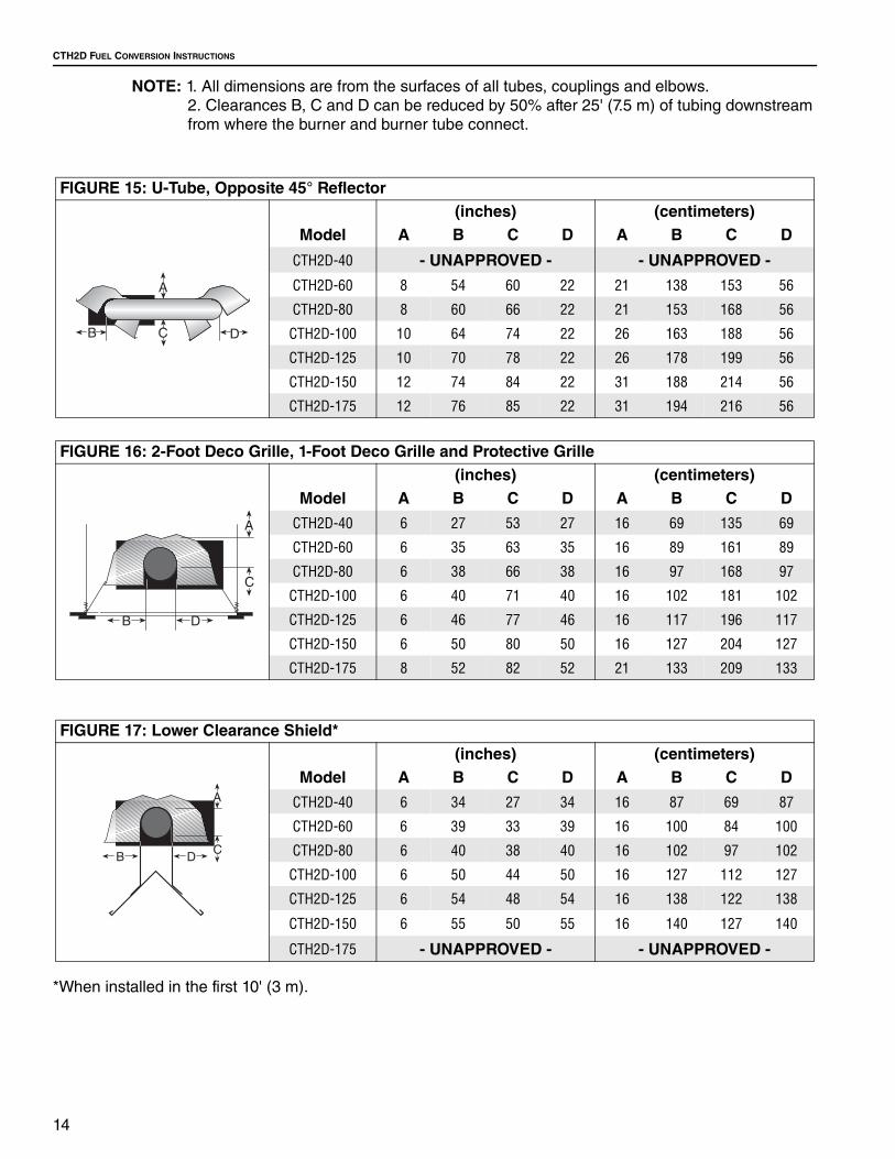
NOTE: 1. All dimensions are from the surfaces of all tubes, couplings and elbows.
2. Clearances B, C and D can be reduced by 50% after 25' (7.5 m) of tubing downstream
from where the burner and burner tube connect.
FIGURE 9: Level Reflector
(inches) (centimeters)
Model A B C D A B C D
CTH2D-40 6 27 53 27 16 69 135 69
CTH2D-60 6 35 63 35 16 89 161 89
CTH2D-80 6 38 66 38 16 97 168 97
CTH2D-100 6 40 71 40 16 102 181 102
CTH2D-125 6 46 77 46 16 117 196 117
CTH2D-150 6 50 80 50 16 127 204 127
CTH2D-175 8 52 82 52 21 133 209 133
FIGURE 10: Level Side Reflector
(inches) (centimeters)
Model A B C D A B C D
CTH2D-40 6 9 53 44 16 23 135 112
CTH2D-60 6 9 63 47 16 23 161 120
CTH2D-80 6 9 70 54 16 23 178 138
CTH2D-100 6 9 77 59 16 23 196 150
CTH2D-125 6 9 83 65 16 23 211 166
CTH2D-150 6 9 86 69 16 23 219 176
CTH2D-175 8 9 88 73 21 23 224 186
FIGURE 11: Two Side Reflectors
(inches) (centimeters)
Model A B C D A B C D
CTH2D-40 6 15 53 15 16 39 135 39
CTH2D-60 6 23 66 23 16 59 168 59
CTH2D-80 6 25 72 25 16 64 183 64
CTH2D-100 6 27 78 27 16 69 199 69
CTH2D-125 6 32 84 32 16 82 214 82
CTH2D-150 6 35 88 35 16 89 224 89
CTH2D-175 8 40 91 40 21 102 232 102

SECTION 6: CLEARANCES TO COMBUSTIBLES
13
NOTE: 1. All dimensions are from the surfaces of all tubes, couplings and elbows.
2. Clearances B, C and D can be reduced by 50% after 25' (7.5 m) of tubing downstream
from where the burner and burner tube connect.
FIGURE 12: 45° Tilt Reflector
(inches) (centimeters)
Model A B C D A B C D
CTH2D-40 8 8 51 46 21 21 130 117
CTH2D-60 8 8 60 54 21 21 153 138
CTH2D-80 8 8 66 60 21 21 168 153
CTH2D-100 10 8 74 64 26 21 188 163
CTH2D-125 10 8 78 69 26 21 199 176
CTH2D-150 12 8 84 74 31 21 214 188
CTH2D-175 12 8 85 79 31 21 216 201
FIGURE 13: U-Tube, Level Reflector
(inches) (centimeters)
Model A B C D A B C D
CTH2D-40 - UNAPPROVED - - UNAPPROVED -
CTH2D-60 6 35 63 30 16 89 161 77
CTH2D-80 6 38 69 37 16 97 176 94
CTH2D-100 6 40 76 39 16 102 194 100
CTH2D-125 6 46 79 43 16 117 201 110
CTH2D-150 6 50 84 47 16 127 214 120
CTH2D-175 8 54 87 51 21 138 221 130
FIGURE 14: U-Tube, 45°
(inches) (centimeters)
Model A B C D A B C D
CTH2D-40 - UNAPPROVED - - UNAPPROVED -
CTH2D-60 8 8 60 42 21 21 153 107
CTH2D-80 8 8 66 46 21 21 168 117
CTH2D-100 8 8 74 52 21 21 188 133
CTH2D-125 8 8 78 61 21 21 199 155
CTH2D-150 8 8 84 66 21 21 214 168
CTH2D-175 8 8 85 70 21 21 216 178
DB
A
C
CTH2D FUEL CONVERSION INSTRUCTIONS
14
NOTE: 1. All dimensions are from the surfaces of all tubes, couplings and elbows.
2. Clearances B, C and D can be reduced by 50% after 25' (7.5 m) of tubing downstream
from where the burner and burner tube connect.
*When installed in the first 10' (3 m).
FIGURE 15: U-Tube, Opposite 45° Reflector
(inches) (centimeters)
Model A B C D A B C D
CTH2D-40 - UNAPPROVED - - UNAPPROVED -
CTH2D-60 8 54 60 22 21 138 153 56
CTH2D-80 8 60 66 22 21 153 168 56
CTH2D-100 10 64 74 22 26 163 188 56
CTH2D-125 10 70 78 22 26 178 199 56
CTH2D-150 12 74 84 22 31 188 214 56
CTH2D-175 12 76 85 22 31 194 216 56
FIGURE 16: 2-Foot Deco Grille, 1-Foot Deco Grille and Protective Grille
(inches) (centimeters)
Model A B C D A B C D
CTH2D-40 6 27 53 27 16 69 135 69
CTH2D-60 6 35 63 35 16 89 161 89
CTH2D-80 6 38 66 38 16 97 168 97
CTH2D-100 6 40 71 40 16 102 181 102
CTH2D-125 6 46 77 46 16 117 196 117
CTH2D-150 6 50 80 50 16 127 204 127
CTH2D-175 8 52 82 52 21 133 209 133
FIGURE 17: Lower Clearance Shield*
(inches) (centimeters)
Model A B C D A B C D
CTH2D-40 6 34 27 34 16 87 69 87
CTH2D-60 6 39 33 39 16 100 84 100
CTH2D-80 6 40 38 40 16 102 97 102
CTH2D-100 6 50 44 50 16 127 112 127
CTH2D-125 6 54 48 54 16 138 122 138
CTH2D-150 6 55 50 55 16 140 127 140
CTH2D-175 - UNAPPROVED - - UNAPPROVED -
SECTION 6: CLEARANCES TO COMBUSTIBLES
15
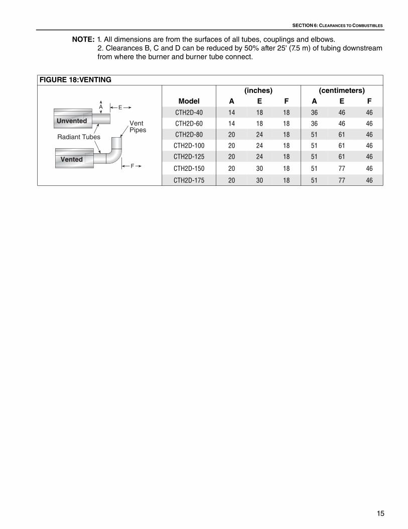
NOTE: 1. All dimensions are from the surfaces of all tubes, couplings and elbows.
2. Clearances B, C and D can be reduced by 50% after 25' (7.5 m) of tubing downstream
from where the burner and burner tube connect.
FIGURE 18:VENTING
(inches) (centimeters)
Model A E F A E F
CTH2D-40 14 18 18 36 46 46
CTH2D-60 14 18 18 36 46 46
CTH2D-80 20 24 18 51 61 46
CTH2D-100 20 24 18 51 61 46
CTH2D-125 20 24 18 51 61 46
CTH2D-150 20 30 18 51 77 46
CTH2D-175 20 30 18 51 77 46
����������
��������
��������
������
� �
�

CTH2D FUEL CONVERSION INSTRUCTIONS
16
SECTION 7: OPERATION AND MAINTENANCE
This heater is equipped with a direct spark ignition
system.
7.1 Sequence of Operation
1. Turn the thermostat up. When the thermostat
calls for heat, the blower motor will energize.
2. When the motor approaches nominal running
RPM, the pressure switch closes and activates
the ignition module.
3. After a 45 second prepurge, the ignition module
then opens the gas valve and energizes the
spark igniter.
4. When the flame is established, the sparking
sequence ceases.
5. If the flame is not established during the ignition
sequence, the ignition module closes the gas
valve and purge begins. Module will try 2
additional times for ignition (with purges in
between trials). If ignition is not established, the
module will lockout.
6. If the flame extinguishes during operation, the
ignition module will attempt the multiple trial
sequence described in step 5. If ignition is not
re-established, the module will lockout for one
hour or until reset.
7. After lockout, the control can be reset by turning
down thermostat for five seconds, and then
raising it again to desired temperature, or by
disconnecting power and then reconnecting.
8. When thermostat is satisfied, all power to the
unit is shut off.
7.2 To Shut Off Heater
Set thermostat to lowest setting.
Turn OFF electric power to heater.
Turn OFF manual gas valve in the heater supply line.
7.3 To Start Heater
Turn gas valve and electric power OFF and wait five
minutes for unburned gases to vent from heater.
Turn ON main gas valve.
Turn ON electric power.
Set thermostat to desired temperature.
Burner should light automatically.
Cut/Pinch Hazard
Wear protective gear during installation, operation and service.
Edges are sharp.
WARNING
Failure to follow these instructions can result in death, electric shock, injury or property damage.
Burn Hazard
Allow heater to cool before service.
Tubing may still be hot after operation.
Explosion Hazard
Turn off gas supply to heater before service.
DANGER
Electrical Shock Hazard
Disconnect electric before service. Heater must be connected to a properly grounded electrical source.

SECTION 7: OPERATION AND MAINTENANCE
17
7.4 Pre-Season Maintenance and Annual
Inspection
To ensure your safety and years of trouble-free
operation of the heating system, service and annual
inspections must be done by a contractor qualified in
the installation and service of gas-fired heating
equipment.
Turn off gas and electric supplies before performing
service or maintenance. Allow heater to cool before
servicing.
Before every heating season, a contractor qualified in
the installation and service of gas-fired heating
equipment must perform a thorough safety
inspection of the heater.
For best performance, the gas, electrical, thermostat
connections, tubing, venting, suspensions and
overall heater condition should be inspected
thoroughly.
NOTE: Gas flow and burner ignition are among the
first things that should be inspected.
Please See Page 17, Section 7.4 for suggested items
to inspect.
7.5 Maintenance Checklist
Installation Code and Annual Inspections:
All installation and service of ROBERTS GORDON®
equipment must be performed by a contractor
qualified in the installation and service of equipment
sold and supplied by Roberts-Gordon LLC and
conform to all requirements set forth in the
ROBERTS GORDON® manuals and all applicable
governmental authorities pertaining to the
installation, service, operation and labeling of the
equipment.
To help facilitate optimum performance and safety,
Roberts-Gordon LLC recommends that a qualified
contractor conduct, at a minimum, annual
inspections of your ROBERTS GORDON® equipment
and perform service where necessary, using only
replacement parts sold and supplied by Roberts-
Gordon LLC.
The Vicinity of the Heater Do not store or use flammable objects, liquids or vapors near the heater.
Immediately remove these items if they are present.
Vehicles and Other
Objects
Maintain the clearances to combustibles.
Do not hang anything from, or place anything on, the heater.
Make sure nothing is lodged underneath the reflector, in between the tubes or
in the decorative or protective grilles (included with select models).
Immediately remove objects in violation of the clearances to combustibles.
Reflector Support reflector with reflector hanger and support strap.
Reflector must not touch tube.
Make sure there is no dirt, sagging, cracking or distortion.
Do not operate if there is sagging, cracking or distortion.
Make sure reflectors are correctly overlapped.
Clean outside surface with a damp cloth.
Vent Pipe Venting must be intact. Using a flashlight, look for obstructions, cracks on the
pipe, gaps in the sealed areas or corrosion.
The area must be free of dirt and dust.
Remove any carbon deposits or scale using a wire brush.
Outside Air Inlet Inlet must be intact. Look for obstructions, cracks on the pipe, gaps in the
sealed areas or corrosion.
The area must be free of dirt and dust. Clean and reinstall as required.
Tubes Make sure there are no cracks.
Make sure tubes are connected and suspended securely.
Make sure there is no sagging, bending or distortion.
Clean or replace as required.
Gas Line Check for gas leaks.

CTH2D FUEL CONVERSION INSTRUCTIONS
18
Burner Observation
Window
Make sure it is clean and free of cracks or holes.
Clean and replace as required.
Blower Scroll, Wheel and
Motor
Compressed air or a vacuum cleaner may be used to clean dust and dirt.
Burner Cup and Orifice Clear of obstructions (even spider webs will cause problems).
Carefully remove any dust and debris from the burner.
Electrode Replace if there are cracked ceramics, excessive carbon residue, or erosion
of the electrode.
The electrode gap should be 1/8" (3.2 mm).
Thermostat There should be no exposed wire or damage to the thermostat.
Suspension Points Make sure the heater is hanging securely. Look for signs of wear on the chain
or ceiling.
Decorative and Protective
Grille (optional)
The grille must be securely attached.
Check that the side reflector extensions are installed correctly and secured in
place if necessary. (Decorative grille only.)
Make sure shield is installed correctly and secured in place if necessary.
(Decorative grille only.)
Lower Clearance Shield
(optional)
The lower shield must be securely attached. Inspect shield support straps
and lower clearance shield anchor points.
Make sure shield is installed correctly and secured in place if necessary.
Wall Tag If wall tag is present, make sure it is legible and accurate. Please contact
Roberts-Gordon LLC or your ROBERTS GORDON® independent distributor,
if you need a wall tag.
Safety Labels Product safety signs or labels should be replaced by the product user when
they are no longer legible. Please contact Roberts-Gordon LLC or your ROB-
ERTS GORDON® independent distributor to obtain replacement signs or
labels.

SECTION 8: THE ROBERTS GORDON® COMPLETETMCTH2D WARRANTY
19
SECTION 8: THE ROBERTS GORDON® COMPLETETMCTH2D WARRANTY
ROBERTS-GORDON LLC WILL PAY FOR:
Within 36 months from date of purchase by buyer or 42 months from date of shipment by Roberts-Gordon LLC (whichever occurs first), replacement parts will be provided free of charge for any part of the product which fails due to a manufacturing or material defect.
Roberts-Gordon LLC will require the part in question to be returned to the factory. Roberts-Gordon LLC will, at its sole discretion, repair or replace after determining the nature of the defect and disposition of part in question.
ROBERTS GORDON® Replacement Parts are warranted for a period of 12 months from date of shipment from Roberts-Gordon LLC or the remaining ROBERTS GORDON® COMPLETETMCTH2D warranty.
ROBERTS-GORDON LLC WILL NOT PAY FOR:
Service trips, service calls and labor charges.
Shipment of replacement parts.
Claims where the total price of the goods have not been paid.
Damage due to:
• Improper installation, operation or maintenance.
• Misuse, abuse, neglect, or modification of the
ROBERTS GORDON® COMPLETETMCTH2D in any
way.
• Use of the ROBERTS GORDON®
COMPLETETMCTH2D for other than its intended
purpose.
• Incorrect gas or electrical supply, accident, fire,
floods, acts of God, war, terrorism, or other casualty.
• Improper service, use of replacement parts or
accessories not specified by Roberts-Gordon.
• Failure to install or maintain the
ROBERTS GORDON® COMPLETETMCTH2D as
directed in the Installation, Operation and Service
Manual.
• Relocation of the ROBERTS GORDON®
COMPLETETMCTH2D after initial installation
• Use of the ROBERTS GORDON®
COMPLETETMCTH2D in a corrosive atmosphere
containing contaminants.
• Use of the ROBERTS GORDON®
COMPLETETMCTH2D in the vicinity of a
combustible or explosive material.
• Any defect in the ROBERTS GORDON®
COMPLETETMCTH2D arising from a drawing,
design, or specification supplied by or on behalf of
the consumer.
• Damage incurred during shipment. Claim must be
filed with carrier.
WARRANTY IS VOID IF:
The ROBERTS GORDON® COMPLETETMCTH2D is not installed by an contractor qualified in the installation and service of gas fired heating equipment.
You cannot prove original purchase date and required annual maintenance history.
The data plate and/or serial number are removed, defaced, modified or altered in any way.
The ownership of the ROBERTS GORDON® COMPLETETMCTH2D is moved or transferred. This warranty is non-transferable.
Roberts-Gordon LLC is not permitted to inspect the damaged equipment and/or component parts.
READ YOUR INSTALLATION, OPERATION AND
SERVICE MANUAL.
If you have questions about your equipment, contact your installing professional. Should you need Replacement Parts or have additional questions, call or write:
Roberts-Gordon LLC
1250 William Street
P.O. Box 44
Buffalo, New York 14240-0044
Telephone: +1.716.852.4400
Fax: +1.716.852.0854
Toll Free: 800.828.7450
www.robertsgordon.com
Roberts-Gordon LLC's liability, and your exclusive remedy, under this warranty or any implied warranty (including the implied warranties of merchantability and fitness for a particular purpose) is limited to providing replacement parts during the term of this warranty. Some jurisdictions do not allow limitations on how long an implied warranty lasts, so this limitation may not apply to you. There are no rights, warranties or conditions, expressed or implied, statutory or otherwise, other than those contained in this warranty.
Roberts-Gordon LLC shall in no event be responsible for incidental or consequential damages or incur liability for damages in excess of the amount paid by you for the ROBERTS GORDON® COMPLETETMCTH2D. Some jurisdictions do not allow the exclusion or limitation of incidental or consequential damages, so this limitation or exclusion may not apply to you. This warranty gives you specific legal rights, and you may also have other rights which vary from jurisdiction to jurisdiction.
Roberts-Gordon LLC shall not be responsible for failure to perform under the terms of this warranty if caused by circumstances out of its control, including but not limited to war, fire, flood, strike, government or court orders, acts of God, terrorism, unavailability of supplies, parts or power. No person is authorized to assume for Roberts-Gordon LLC any other warranty, obligation or liability.
LIMITATIONS ON AUTHORITY OF
REPRESENTATIVES:
No representative of Roberts-Gordon LLC, other than an Executive Officer, has authority to change or extend these provisions. Changes or extensions shall be binding only if confirmed in writing by Roberts-Gordon LLC's duly authorized Executive Officer.

CTH2D FUEL CONVERSION INSTRUCTIONS
20

SECTION 8: THE ROBERTS GORDON® COMPLETETMCTH2D WARRANTY
21
