fuel as secondary refrigerant on lpg fuelled vehicle: a
TRANSCRIPT
Journal of Mechanical Engineering and Sciences
ISSN (Print): 2289-4659; e-ISSN: 2231-8380
Volume 13, Issue 1, pp. 4390-4402, March 2019
© Universiti Malaysia Pahang, Malaysia
DOI: https://doi.org/10.15282/jmes.13.1.2019.04.0374
4390
Fuel as secondary refrigerant on LPG fuelled vehicle: A thermodynamics analysis
M. Setiyo1*and B. Waluyo2
1,2Department of Automotive Engineering, Universitas Muhammadiyah Magelang
Jl. Bambang Soegeng, Mertoyudan, Magelang 56172, Indonesia
Phone: +6293326945; Fax: +6293325554 *Email: [email protected]
ABSTRACT
In LPG-fuelled vehicles, there is a potential cooling from LPG evaporation in the fuel line.
Cooling power is obtained without reducing the caloric value of the fuel supplied to the
engine. Thus, LPG functions like a refrigerant before it is burned in the combustion chamber.
Consequently, there is a change in fuel efficiency. Therefore, this paper presents a new
thermodynamic analysis of LPG-fuelled vehicles by harvesting cooling power in the fuel
line. The research was conducted by simulating LPG mass flow rates of 1-6 g/s on 1998 cm3
engine which represent the fuel consumption of passenger cars. The total fuel efficiency is
calculated by summing the indicated thermal power added by cooling power to the fuel
energy supplied. The results show that the cooling power from the fuel line can increase the
total fuel efficiency of 3.16%.
Keywords: LPG fuelled vehicle; LPG evaporation; cooling power; total fuel efficiency.
INTRODUCTION
In the last few decades, LPG vehicle technology has rapidly developed [1]. Initially, LPG is
supplied to the engine through a Converter and Mixer (CM) like a carburetor in the gasoline
engine. CM LPG kit is the first generation but is still widely used today, especially
applications on vehicles that are modified for LPG experiences. The engine performance with
the CM LPG kits heavily depends on mixer design and adjustment on the converter. Output
power from CM LPG kits is reportedly lower than gasoline due to volumetric efficiency
factor [2-4]. Then, the LPG kit technology evolved into Vapor Phase Injection (VPI) as a
second generation, where the amount of LPG supplied to the engine began controlled with
electronics and pneumatic. VPI LPG kit leaves mixer and replaces it with injectors/splitters.
The third generation of LPG kit evolves into Liquid Phase Injection (LPI), where liquid phase
LPG is in a pressure regulated fuel rail. The third generation already involves many sensors;
the LPG ECM controls the injectors to supply LPG from the fuel rail with a set amount to
achieve the right mix, generating higher output power and lower emissions, compared to the
previous generations. The recent technology is the fourth generation called Liquid Phase
Direct Injection (LPDI), the liquid phase LPG is injected into the combustion chamber like
Gasoline Direct Injection (GDI). The loss of volumetric efficiency in the first to third
generation has been recoverable with LPDI. LPI and LPDI LPG kits are commonly used in
M. Setiyo et. al / Journal of Mechanical Engineering and Sciences 13(1) 2019 4390-4402
4391
vehicles designed for LPG applications. Meanwhile, CM and VPI are widely used on
modified vehicles for LPG applications.
LPG was chosen because it has almost all the fundamental properties as an S.I engine
fuel. In the complete combustion, emissions from LPG engine are lower than gasoline
engines because of low carbon content, i.e., three carbon and four carbon for propane and
butane, respectively [5,6]. The resistance to the knocking of LPG is also better than gasoline
due to higher octane numbers which reported of 105-106, depending on the composition [7-
9]. However, because the energy content per unit volume is smaller than gasoline, the output
power generated by the LPG engine is lower than the gasoline engine. Many researchers
agree that the decrease in output power is due to intake air displaced by fuel [10-13].
With continuous research activities, the output power and emissions from LPG
vehicles can be improved at varying levels by adjusting the ignition timing, modifying engine
component, and increasing the compression ratio [7],[14-18]. Other efforts to improve the
output power and emissions are also done through LPG temperature management on the fuel
rail [19] and modification on the valve lifter combined with injection duration management
[20]. Recently, another study tested the LPG consumption compared to RON 95 gasoline in
the same driving mode [21]. As a result, LPG consumption is lower at 1.16 MJ/km from the
gasoline consumption in the same driving mode. From the articles studied by authors in
present work, it can be concluded that LPG is still a promising fuel for the next few decades.
The thermodynamic equation for measuring the performance of internal combustion
engines is by Air Standard Efficiency (𝜂𝐴𝑆𝐸) and Indicated Thermal Efficiency (𝜂𝐼𝑇𝐸) [22].
𝜂𝐴𝑆𝐸 calculates the potential of thermal utilization based on adiabatic compression ratio
regardless of the combustion process, given in Eq. (1). 𝑟 is the engine compression ratio and
𝑘 is the adiabatic index for air (1.4). Meanwhile, 𝜂𝐼𝑇𝐸 compares the indicated power to the
energy supplied in fuel energy given in Eq. (2). 𝑃𝑖 is the indicated power and �̇�𝑓 is the energy
supplied by fuel (mass flow rate of fuel kg/s × calorific value kJ/kg). Indicated Thermal
Efficiency depends on the energy content of the fuel, combustion process, heat losses, and
mechanical losses that occur.
𝜂𝐴𝑆𝐸 = 1 −1
𝑟(𝑘−1) (1)
𝜂𝐼𝑇𝐸 =𝑃𝑖
�̇�𝑓 (2)
On the other hand, the air conditioning (A/C) system has become one of the main
accessories in passenger vehicles to improve ride comfort. Initially, the A/C system only
works to regulate the air temperature and humidity [23]. Now, many changes have been made
to meet passenger comfort and health needs, save fuel, and improve environmental
acceptance [24,25]. The general definition of the A/C system discusses heating and cooling.
However, in this study only presents the A/C system that serves as a cooling and maybe
dehumidifying. In its development, the cooling system on the vehicle is not limited only to
passenger cars but to more extensive applications, including the refrigeration system for food
transport vehicle [26-27].
To date, almost all A/C systems for commercial vehicles operate by the vapor
compression system in which the compressor takes power from the engine. As compensation,
fuel consumption and CO2 exhaust emissions increased significantly to achieve comfortable
Fuel as secondary refrigerant on LPG fuelled vehicle: A thermodynamics analysis
4392
temperature and humidity inside the cabin [28,29]. A study conducted by ADEME on a
gasoline engine tested with urban cycles at 40 °C of environmental temperature showed that
fuel consumption due to A/C systems increased 40% [30]. A similar study showed that fuel
consumption with AC operation for sedans increased 20-25% [31]. Even, when the engine
operates at idling, the wasted fuel for the A/C system more than at medium speed and high
speed [32,33]. In another study, the wasted fuel due to the use of A/C systems for cabin
cooling in Europe accounted for 3.2% of total global fuel consumption [34]. Although in
different numbers, the A/C system on the vehicle becomes a significant load on the engine
that needs fuel. On the other hand, almost all trends in automotive development are to
increase efficiency and reduce emissions [35-37].
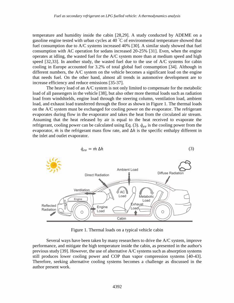
The heavy load of an A/C system is not only limited to compensate for the metabolic
load of all passengers in the vehicle [38], but also other more thermal loads such as radiation
load from windshields, engine load through the steering column, ventilation load, ambient
load, and exhaust load transferred through the floor as shown in Figure 1. The thermal loads
on the A/C system must be exchanged for cooling power on the evaporator. The refrigerant
evaporates during flow in the evaporator and takes the heat from the circulated air stream.
Assuming that the heat released by air is equal to the heat received to evaporate the
refrigerant, cooling power can be calculated using Eq. (3). �̇�𝑒𝑣 is the cooling power from the
evaporator, �̇� is the refrigerant mass flow rate, and Δℎ is the specific enthalpy different in
the inlet and outlet evaporator.
�̇�𝑒𝑣 = �̇� Δℎ (3)
Figure 1. Thermal loads on a typical vehicle cabin
Several ways have been taken by many researchers to drive the A/C system, improve
performance, and mitigate the high temperature inside the cabin, as presented in the author's
previous study [39]. However, the use of alternative A/C systems such as absorption systems
still produces lower cooling power and COP than vapor compression systems [40-43].
Therefore, seeking alternative cooling systems becomes a challenge as discussed in the
author present work.
M. Setiyo et. al / Journal of Mechanical Engineering and Sciences 13(1) 2019 4390-4402
4393
In 2004, an experimental study to calculate LPG requirements on a Ford Focus to
produce equivalent power output when driven by gasoline was done by Price et al. [44].
Because LPG in a tank is liquid and enters the engine as a vapor, Price's study also discusses
in detail the heat required to evaporate LPG (at varying mass flow rates) supplied from a
portion of the engine coolant flow. As a result, there was a 7 °C temperature drop from the
engine coolant that crosses the evaporator with the flow rate of 0.1 kg/s at full engine load
(�̇�LPG = 6 g/s). However, this potential has not been utilized; cooling recovery is still wasted
with engine coolant. Although LPG can evaporate perfectly in the evaporator, the LPG
temperature at the exit of the evaporator reaches more than 70 °C. With high temperature
(superheated vapor), the energy density of LPG becomes lower and allows to reduce
volumetric efficiency. In fact, the boiling temperature of LPG at evaporative pressure is
below 0 °C. It is possible to evaporate LPG with ambient air to produce cooling power.
The experiment to harvest the cooling effect from LPG flow is known as zero cost
refrigeration [45]. The LPG pressure from the household cylinder is lowered using a capillary
tube placed in a cooling box before LPG is delivered to the burner. Then, this concept is
further discussed by Ghariya et al. [46] as the thermodynamic evolution of the cooling
system. In the recent study conducted by present authors [47], LPG engines have been shown
to produce cooling power above 1.0 kW in eco-driving mode. Assuming that LPG
consumption is linear to the engine loads as presented by Masi and Gobbato [10], and the
heat exchange in the evaporator occurs perfectly, its cooling power potential is hihger than
the results of a recent study. LPG has a good capability as an alternative refrigerant that is
more environmentally friendly, as has been tested by many researchers as a replacement for
the refrigerant in domestic refrigerators or vehicles [48-52]. From previous studies, the
thermodynamic analysis was performed separately for the engine (combustion) and cooling
systems. Given that in this study, LPG before being used as a fuel used as a refrigerant, it is
necessary to analyse and evaluate the thermodynamic equations which make it possible to
create equations as a hybrid system.
METHOD
System Description
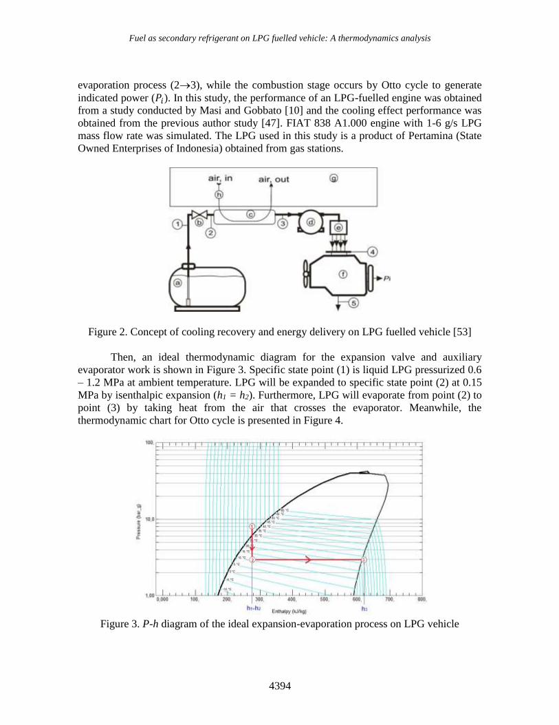
In a previous authors work [47], a model of a cooling system in an LPG fuelled vehicle was
successfully tested as a secondary system as shown in Figure 2. First, Pressurized LPG is in
a tank equipped with a deep tube (a) to guarantee LPG out of the tank in a liquid state. An
expansion valve (b) is installed on the fuel line as a pressure reducer. An auxiliary evaporator
(c) is installed after the expansion valve as a heat exchanger. As long as LPG flows in the
evaporator, LPG evaporates by taking the heat from the air across the evaporator due to the
drive from the electric blower (h). In this case, LPG functions like a refrigerant. As a result,
the air temperature at the exit of the evaporator is lower than when it enters the evaporator
that means produce a cooling power inside the cabin (g). Furthermore, LPG is received by
the regulator (d) and forwarded to the mixer (e). Regulator functions to adjust the LPG flow
rate based on the engine need. Finally, LPG goes into the engine (f) as fuel.
Looking for Fig. 2, there are two thermodynamic stages, the cooling stage (13) and
combustion stage (45). The cooling stage consists of expansion process (12) and
Fuel as secondary refrigerant on LPG fuelled vehicle: A thermodynamics analysis
4394
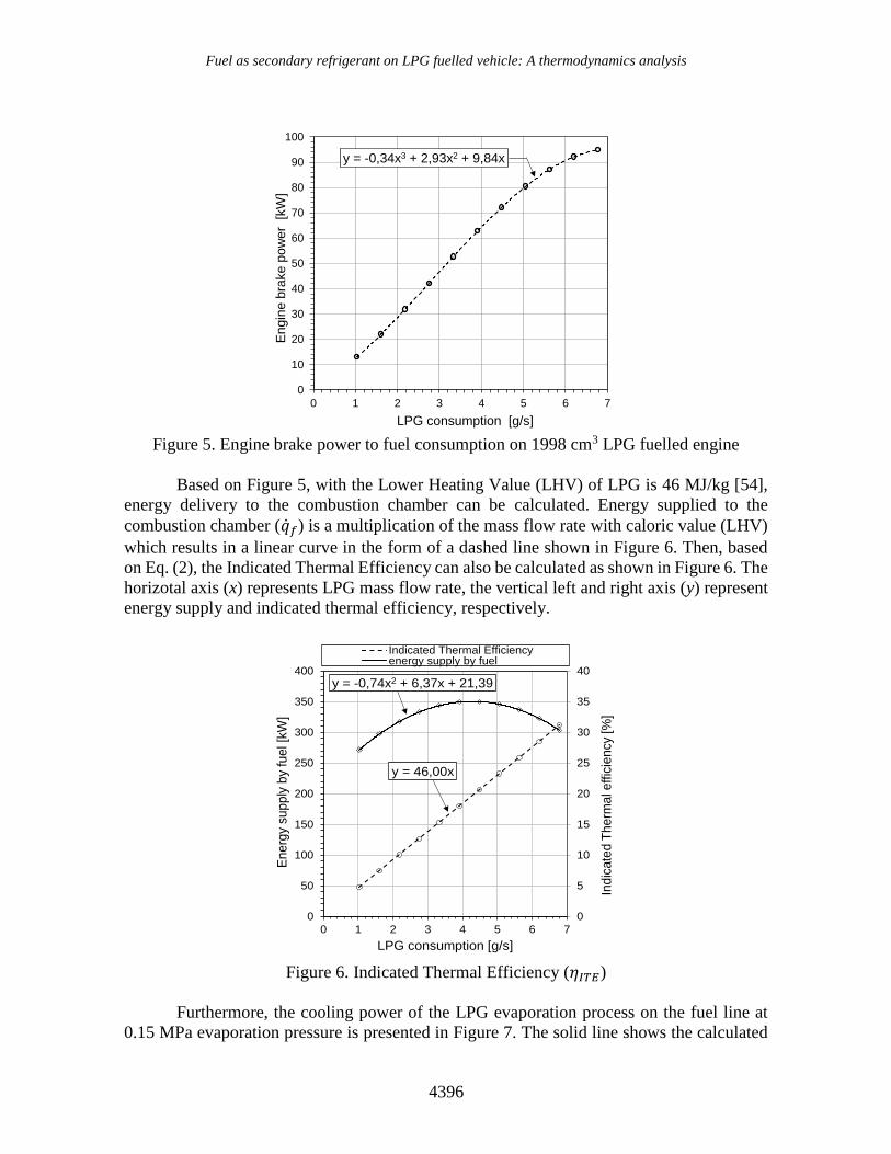
evaporation process (23), while the combustion stage occurs by Otto cycle to generate
indicated power (𝑃𝑖). In this study, the performance of an LPG-fuelled engine was obtained
from a study conducted by Masi and Gobbato [10] and the cooling effect performance was
obtained from the previous author study [47]. FIAT 838 A1.000 engine with 1-6 g/s LPG
mass flow rate was simulated. The LPG used in this study is a product of Pertamina (State
Owned Enterprises of Indonesia) obtained from gas stations.
Figure 2. Concept of cooling recovery and energy delivery on LPG fuelled vehicle [53]
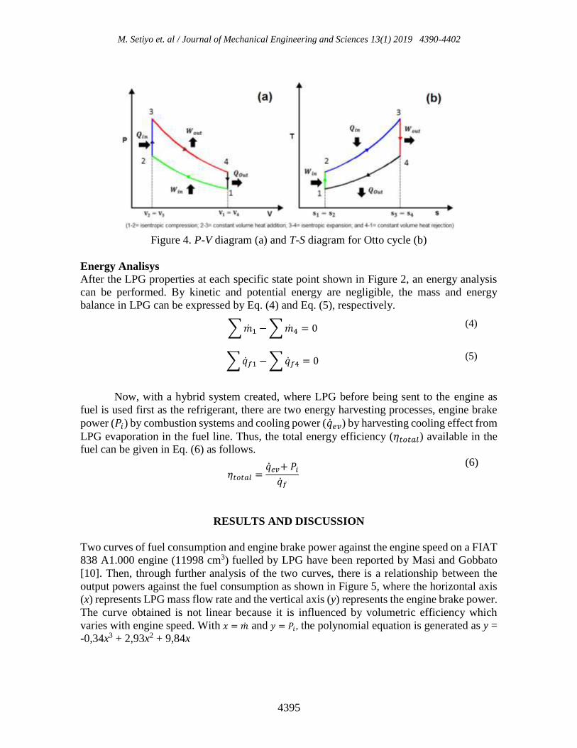
Then, an ideal thermodynamic diagram for the expansion valve and auxiliary
evaporator work is shown in Figure 3. Specific state point (1) is liquid LPG pressurized 0.6
– 1.2 MPa at ambient temperature. LPG will be expanded to specific state point (2) at 0.15
MPa by isenthalpic expansion (h1 = h2). Furthermore, LPG will evaporate from point (2) to
point (3) by taking heat from the air that crosses the evaporator. Meanwhile, the
thermodynamic chart for Otto cycle is presented in Figure 4.
Figure 3. P-h diagram of the ideal expansion-evaporation process on LPG vehicle
M. Setiyo et. al / Journal of Mechanical Engineering and Sciences 13(1) 2019 4390-4402
4395
Figure 4. P-V diagram (a) and T-S diagram for Otto cycle (b)
Energy Analisys
After the LPG properties at each specific state point shown in Figure 2, an energy analysis
can be performed. By kinetic and potential energy are negligible, the mass and energy
balance in LPG can be expressed by Eq. (4) and Eq. (5), respectively.
∑ �̇�1 − ∑ �̇�4 = 0 (4)
∑ �̇�𝑓1 − ∑ �̇�𝑓4 = 0 (5)
Now, with a hybrid system created, where LPG before being sent to the engine as
fuel is used first as the refrigerant, there are two energy harvesting processes, engine brake
power (𝑃𝑖) by combustion systems and cooling power (�̇�𝑒𝑣) by harvesting cooling effect from
LPG evaporation in the fuel line. Thus, the total energy efficiency (𝜂𝑡𝑜𝑡𝑎𝑙) available in the
fuel can be given in Eq. (6) as follows.
𝜂𝑡𝑜𝑡𝑎𝑙 =�̇�𝑒𝑣+ 𝑃𝑖
�̇�𝑓
(6)
RESULTS AND DISCUSSION
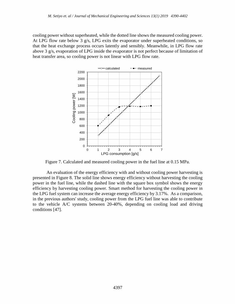
Two curves of fuel consumption and engine brake power against the engine speed on a FIAT
838 A1.000 engine (11998 cm3) fuelled by LPG have been reported by Masi and Gobbato
[10]. Then, through further analysis of the two curves, there is a relationship between the
output powers against the fuel consumption as shown in Figure 5, where the horizontal axis
(x) represents LPG mass flow rate and the vertical axis (y) represents the engine brake power.
The curve obtained is not linear because it is influenced by volumetric efficiency which
varies with engine speed. With 𝑥 = �̇� and 𝑦 = 𝑃𝑖 , the polynomial equation is generated as y =
-0,34x3 + 2,93x2 + 9,84x
Fuel as secondary refrigerant on LPG fuelled vehicle: A thermodynamics analysis
4396
Figure 5. Engine brake power to fuel consumption on 1998 cm3 LPG fuelled engine
Based on Figure 5, with the Lower Heating Value (LHV) of LPG is 46 MJ/kg [54],
energy delivery to the combustion chamber can be calculated. Energy supplied to the
combustion chamber (�̇�𝑓) is a multiplication of the mass flow rate with caloric value (LHV)
which results in a linear curve in the form of a dashed line shown in Figure 6. Then, based
on Eq. (2), the Indicated Thermal Efficiency can also be calculated as shown in Figure 6. The
horizotal axis (x) represents LPG mass flow rate, the vertical left and right axis (y) represent
energy supply and indicated thermal efficiency, respectively.
Figure 6. Indicated Thermal Efficiency (𝜂𝐼𝑇𝐸)
Furthermore, the cooling power of the LPG evaporation process on the fuel line at
0.15 MPa evaporation pressure is presented in Figure 7. The solid line shows the calculated
y = -0,34x3 + 2,93x2 + 9,84x
0
10
20
30
40
50
60
70
80
90
100
0 1 2 3 4 5 6 7
Engin
e b
rake p
ow
er
[kW
]
LPG consumption [g/s]
y = 46,00x
y = -0,74x2 + 6,37x + 21,39
0
5
10
15
20
25
30
35
40
0
50
100
150
200
250
300
350
400
0 1 2 3 4 5 6 7
Ind
ica
ted
Th
erm
al e
ffic
ien
cy
[%]
Energ
y supp
ly b
y fu
el[k
W]
LPG consumption [g/s]
Indicated Thermal Efficiencyenergy supply by fuel
M. Setiyo et. al / Journal of Mechanical Engineering and Sciences 13(1) 2019 4390-4402
4397
cooling power without superheated, while the dotted line shows the measured cooling power.
At LPG flow rate below 3 g/s, LPG exits the evaporator under superheated conditions, so
that the heat exchange process occurs latently and sensibly. Meanwhile, in LPG flow rate
above 3 g/s, evaporation of LPG inside the evaporator is not perfect because of limitation of
heat transfer area, so cooling power is not linear with LPG flow rate.
Figure 7. Calculated and measured cooling power in the fuel line at 0.15 MPa.
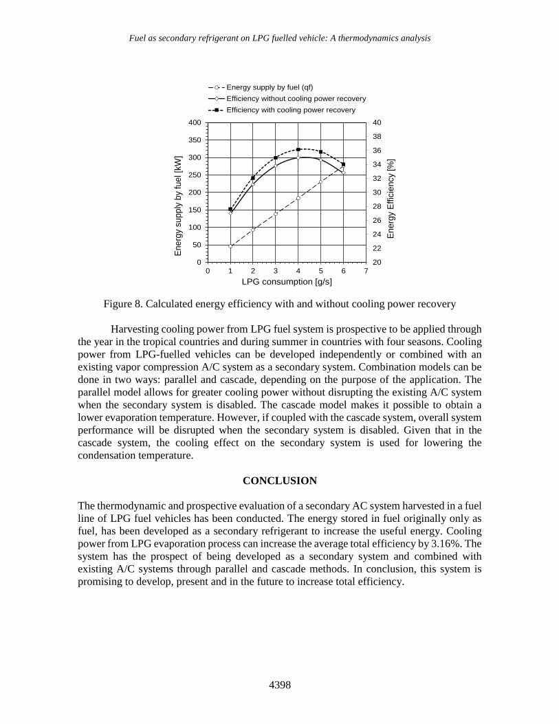
An evaluation of the energy efficiency with and without cooling power harvesting is
presented in Figure 8. The solid line shows energy efficiency without harvesting the cooling
power in the fuel line, while the dashed line with the square box symbol shows the energy
efficiency by harvesting cooling power. Smart method for harvesting the cooling power in
the LPG fuel system can increase the average energy efficiency by 3.17%. As a comparison,
in the previous authors' study, cooling power from the LPG fuel line was able to contribute
to the vehicle A/C systems between 20-40%, depending on cooling load and driving
conditions [47].
0
200
400
600
800
1000
1200
1400
1600
1800
2000
2200
0 1 2 3 4 5 6 7
Co
olin
g p
ow
er
[W]
LPG consumption [g/s]
calculated measured
Fuel as secondary refrigerant on LPG fuelled vehicle: A thermodynamics analysis
4398
Figure 8. Calculated energy efficiency with and without cooling power recovery
Harvesting cooling power from LPG fuel system is prospective to be applied through
the year in the tropical countries and during summer in countries with four seasons. Cooling
power from LPG-fuelled vehicles can be developed independently or combined with an
existing vapor compression A/C system as a secondary system. Combination models can be
done in two ways: parallel and cascade, depending on the purpose of the application. The
parallel model allows for greater cooling power without disrupting the existing A/C system
when the secondary system is disabled. The cascade model makes it possible to obtain a
lower evaporation temperature. However, if coupled with the cascade system, overall system
performance will be disrupted when the secondary system is disabled. Given that in the
cascade system, the cooling effect on the secondary system is used for lowering the
condensation temperature.
CONCLUSION
The thermodynamic and prospective evaluation of a secondary AC system harvested in a fuel
line of LPG fuel vehicles has been conducted. The energy stored in fuel originally only as
fuel, has been developed as a secondary refrigerant to increase the useful energy. Cooling
power from LPG evaporation process can increase the average total efficiency by 3.16%. The
system has the prospect of being developed as a secondary system and combined with
existing A/C systems through parallel and cascade methods. In conclusion, this system is
promising to develop, present and in the future to increase total efficiency.
20
22
24
26
28
30
32
34
36
38
40
0
50
100
150
200
250
300
350
400
0 1 2 3 4 5 6 7
Energ
y E
ffic
iency
[%]
Energ
y supply
by
fuel [k
W]
LPG consumption [g/s]
Energy supply by fuel (qf)
Efficiency without cooling power recovery
Efficiency with cooling power recovery
M. Setiyo et. al / Journal of Mechanical Engineering and Sciences 13(1) 2019 4390-4402
4399
ACKNOWLEDGMENT
This paper is part of the project of hybrid A/C system development on LPG-fuelled vehicles
which is conducted at the Automotive Laboratory of Universitas Muhammadiyah Magelang.
The patents of the systems and equipment presented in this article have been registered in
Indonesia by the principal author with ID number of IDS000001811 and P00201709446.
NOMENCLATURE
�̇� LPG mass flow rate [g/s]
ℎ Specific enthalpy [kJ kg-1]
�̇�𝑒𝑣 Cooling power [kW]
�̇�𝑓 Energy supplied by fuel (mass flow rate × calorific value) [kW]
𝑃𝑖 Engine brake power [kW]
𝑟 Compression ratio
𝑘 Adiabatic index of air (𝐶𝑝/𝐶𝑉)
ABBREVIATION
A/C Air Conditioning
LPG Liquefied Petroleum Gas
ASE Air Standard Efficiency
ITE Indicated Thermal Efficiency
COP Coefficient of Performance
LHV Lower Heating Value
REFERENCES
[1] World LPG Association, Autogas Incentive Policies, 2017 Edition. Neuilly-sur-Seine
2017.
[2] Erkus B, Sürmen A, Karamangil, MI. A comparative study of carburation and
injection fuel supply methods in an LPG-fuelled SI engine. Fuel 2013;107:511–517.
[3] Gumus M. Effects of volumetric efficiency on the performance and emissions
characteristics of a dual fueled (gasoline and LPG) spark ignition engine. Fuel
Processing Technology 2011;92:1862–1867.
[4] Setiyo M, Waluyo B, Husni M, Karmiadji DW. Characteristics of 1500 CC LPG
fueled engine at various of mixer venturi area applied on Tesla A-100 LPG vaporizer.
Jurnal Teknologi 2016;78(10):43–49.
[5] ETSAP. Automotive LPG and Natural Gas Engines. © IEA ETSAP - Technology
Brief T03 2010;April:1–5.
[6] Chitragar PR, Shivaprasad KV, Nayak V, Bedar P, Kumar GN. An Experimental
Study on Combustion and Emission Analysis of Four Cylinder 4-Stroke Gasoline
Fuel as secondary refrigerant on LPG fuelled vehicle: A thermodynamics analysis
4400
Engine Using Pure Hydrogen and LPG at Idle Condition. Energy Procedia
2015;90:525–534.
[7] Gong C, Wei F, Si X, Liu F. Effects of injection timing of methanol and LPG
proportion on cold start characteristics of SI methanol engine with LPG enriched port
injection under cycle-by-cycle control. Energy 2018;144:54–60.
[8] Duc KN, Tien HN, Duy VN. Performance enhancement and emission reduction of
used motorcycles using flexible fuel technology. Energy for Sustainable
Development 2018;43:60–67.
[9] Morganti KJ, Foong TM, Brear MJ, Da Silva G, Yang Y, Dryer FL. The research and
motor octane numbers of Liquefied Petroleum Gas (LPG). Fuel 2013;108:797–811.
[10] Masi M, Gobbato P. Measure of the volumetric efficiency and evaporator device
performance for a liquefied petroleum gas spark ignition engine. Energy Conversion
and Management 2012;60:18–27.
[11] Ceviz MA, Yüksel F. Cyclic variations on LPG and gasoline-fuelled lean burn SI
engine. Renewable Energy 2006;31:1950–1960.
[12] Campbell M, Wyszyński LP, and Stone R. Combustion of LPG in a Spark-Ignition
Engine. SAE Technical Paper 2004:1–9.
[13] Manzie C, Watson H, Palaniswami M. Air Fuel Ratio Control In Liquefied Petroleum
Gas Injected SI Engines. 15th Triennial World Congress. 2002.
[14] Erkus B, Surmen A, Karamangil MI, Arslan R, Kaplan C. The effect of ignition
timing on performance of LPG injected SI engine. Energy Education Science and
Technology Part A-Energy Science and Research 2012;28:1199–1206.
[15] Erkuş B, Karamangil MI, Sürmen A. Enhancing the heavy load performance of a
gasoline engine converted for LPG use by modifying the ignition timings. Applied
Thermal Engineering 2015;85:188–194.
[16] Kaleli A, Ceviz MA, Erenturk K. Controlling spark timing for consecutive cycles to
reduce the cyclic variations of SI engines. Applied Thermal Engineering 2015;
87:624–632.
[17] Lawankar SM. Comparative Study of Performance of LPG Fuelled Si Engine at
Different Compression Ratio and Ignition Timing. International Journal of
Mechanical Engineering and Technology 2012;3:337–343.
[18] Ravi K, Porpatham E. Effect of piston geometry on performance and emission
characteristics of an LPG fuelled lean burn SI engine at full throttle condition.
Applied Thermal Engineering 2017;110:1051–1060.
[19] Ceviz MA, Kaleli A, Güner E. Controlling LPG temperature for SI engine
applications. Applied Thermal Engineering 2015;82:298–305.
[20] Çinar C, Şahin F, Can Ö, Uyumaz A. A comparison of performance and exhaust
emissions with different valve lift profiles between gasoline and LPG fuels in a SI
engine. Applied Thermal Engineering 2016;107:1261–1268.
[21] Suyabodha A. Comparison the Rate of Energy Consumption between Gasoline95 and
LPG in Spark Ignition Engine under Real Driving Conditions. Energy Procedia
2017;118:164–171.
[22] Bonnics A. Automotive Science and Mathematics, First edit. Oxford: Elsevier Ltd,
2008.
[23] Bhatti MS. Evolution of Automotive Air Conditioning Riding in Comfort: Part II.
ASHRAE Journal. 1999;41:44–50.
M. Setiyo et. al / Journal of Mechanical Engineering and Sciences 13(1) 2019 4390-4402
4401
[24] Nagengast B. 100 Years of Air Conditioning. ASHRAE Journal. 2002;June:44–46.
[25] Shah RK. Automotive Air-Conditioning Systems—Historical Developments, the
State of Technology, and Future Trends. Heat Transfer Engineering 2009;30:720–
735.
[26] Fick T. Transport Refrigeration. Upper Great Plains Transportation Institute, North
Dakota State University. Dakota. 2007:2007.
[27] Tassou JLSA, De-Lille G. Food transport refrigeration. Centre for Energy and Built
Environment Research, School of Engineering and Design, Brunel University, UK.
2012:1–25.
[28] Farrington R, Rugh J. Impact of Vehicle Air-Conditioning on Fuel Economy,
Tailpipe Emissions, and Electric Vehicle Range. Earth Technologies Forum. 2000.
[29] Abas MA, Salim WSW, Ismail MI, Rajoo S, and Martinez-Botas R. Fuel
consumption evaluation of SI engine using start-stop technology. Journal of
Mechanical Engineering and Sciences 2017;11: 2967–2978.
[30] Benouali J. Fuel Consumption of Mobile Air Conditioning Method of Testing and
Results. The Earth Technology Forum. 2003.
[31] Bharathan D, Chaney L, Farrington RB, Lustbader J, Keyser M, Rugh JP. An
overview of vehicle test and analysis results from NREL’s A/C fuel use reduction
research. VTMS 8 - Vehicle Thermal Management Systems Conference and
Exhibition. 2007;June:567–580.
[32] Huff S, West B, Thomas J. Effects of Air Conditioner Use on Real-World Fuel
Economy. SAE Technical Paper. 2103.
[33] Lee J, Kim J, Park J, Bae C. Effect of the air-conditioning system on the fuel economy
in a gasoline engine vehicle. Proceedings of the Institution of Mechanical Engineers,
Part D: Journal of Automobile Engineering 2013;227:66–77.
[34] Rugh J, Hovland V, Andersen S.Significant Fuel Savings and Emission Reductions
by Improving Vehicle Air Conditioning. 15th Annual Earth Technologies Forum and
Mobile Air Conditioning Summit. 2004.
[35] Hairuddin A A, Wandel AP, Yusaf T. An Introduction to a Homogeneous Charge
Compression Ignition Engine. Journal of Mechanical Engineering and Sciences
2014;7:1042–1052.
[36] Salim WSIW, Mahdi AAM, Ismail MI, Abas MA, Martinez-Botas RF, Rajoo S.
Benefits of spark-ignition engine fuel-saving technologies under transient part load
operations. Journal of Mechanical Engineering and Sciences 2017;4:2289–4659.
[37] Wahono B, Nur A, Santoso WB, Praptijanto A. A comparison study of range-
extended engines for electric vehicle based on vehicle simulator. Journal of
Mechanical Engineering and Sciences 2016;10:1803–1816.
[38] Fayazbakhsh MA, Bahrami M. Comprehensive Modeling of Vehicle Air
Conditioning Loads Using Heat Balance Method. SAE Technical Paper.2013.
[39] Setiyo M, Soeparman S, Wahyudi S, Hamidi N. The Alternative Way to Drive the
Automobile Air-Conditioning, Improve Performance, and Mitigate the High
Temperature: A Literature Overview. Periodica Polytechnica Transportation
Engineering 2018;46:36–41.
[40] Vasta S, Freni A, Sapienza A, Costa F, Restuccia G, Development and lab-test of a
mobile adsorption air-conditioner. International Journal of Refrigeration 2012;3:701–
708.
Fuel as secondary refrigerant on LPG fuelled vehicle: A thermodynamics analysis
4402
[41] Aleixo A, Morais S, Cabezas-gómez L, Ricardo J. Using engine exhaust gas as energy
source for an absorption refrigeration system. Applied Energy 2010;87:1141–1148.
[42] Ponce Arrieta FR, Sodré JR, Mateus Herrera MD, Barros Zárante PHB.
Exergoeconomic analysis of an absorption refrigeration and natural gas-fueled diesel
power generator cogeneration system. Journal of Natural Gas Science and
Engineering 2016;36:155–164.
[43] Rêgo AT, Hanriot SM, Oliveira AF, Brito P, Rêgo TFU. Automotive exhaust gas
flow control for an ammonia-water absorption refrigeration system. Applied Thermal
Engineering 2014;64:101–107.
[44] Price P, Guo S, Hirschmann M. Performance of an evaporator for a LPG powered
vehicle. Applied Thermal Engineering 2004;24:1179–1194.
[45] Mohan M. Zero Cost Refrigeration and Air Conditioning Using LPG. Tech Briefs,
Chennai, 2013.
[46] Ghariya VJ, Gosai DC, Gajjar SR. Thermodynamically Evolution of LPG
Refrigerator : A Literature Review. International Journal of Engineering Research &
Technology 2013;2:2868–2875.
[47] Setiyo M, Soeparman S, Hamidi N, Wahyudi S. Cooling effect characteristics of a ½
cycle refrigeration system on an LPG fuel system. International Journal of
Refrigeration 2017;82:227–237.
[48] Alsaad MA, Hammad MA. The application of propane/butane mixture for domestic
refrigerators. Applied Thermal Engineering 1998;18:911–918.
[49] Palm B. Hydrocarbons as refrigerants in small heat pump and refrigeration systems –
A review. International Journal of Refrigeration 2008;31:552–563.
[50] Calm JM. The next generation of refrigerants – Historical review, considerations, and
outlook. International Journal of Refrigeration 2008;31:1123–1133.
[51] Dalkilic AS, Wongwises S. A performance comparison of vapour-compression
refrigeration system using various alternative refrigerants. International
Communications in Heat and Mass Transfer 2010;37:1340–1349.
[52] El-Morsi M. Energy and exergy analysis of LPG (liquefied petroleum gas) as a drop
in replacement for R134a in domestic refrigerators. Energy 2015;86:344–353.
[53] Setiyo M, Wahyudi S, Hamidi N, Soeparman S. Alat Refrigerasi Dari Proses
Evaporasi LPG Pada Kendaraan Berbahan Bakar LPG (Refrigeration Equipment
From LPG Evaporation Process in LPG Fueled Vehicles). IDS000001811. 2018.
[54] Staffel I. The Energy and Fuel Data Sheet. Claverton Energy Research Goup, 2011.